transmission property and evanescent wave absorption of
TRANSCRIPT

Old Dominion UniversityODU Digital CommonsElectrical & Computer Engineering FacultyPublications Electrical & Computer Engineering
2003
Transmission Property and Evanescent WaveAbsorption of Cladded Multimode Fiber TapersShangping Guo
Sacharia Albin
Follow this and additional works at: https://digitalcommons.odu.edu/ece_fac_pubs
Part of the Electrical and Computer Engineering Commons
This Article is brought to you for free and open access by the Electrical & Computer Engineering at ODU Digital Commons. It has been accepted forinclusion in Electrical & Computer Engineering Faculty Publications by an authorized administrator of ODU Digital Commons. For more information,please contact [email protected].
Repository CitationGuo, Shangping and Albin, Sacharia, "Transmission Property and Evanescent Wave Absorption of Cladded Multimode Fiber Tapers"(2003). Electrical & Computer Engineering Faculty Publications. 72.https://digitalcommons.odu.edu/ece_fac_pubs/72
Original Publication CitationGuo, S. P., & Albin, S. (2003). Transmission property and evanescent wave absorption of cladded multimode fiber tapers. OpticsExpress, 11(3), 215-223. doi: 10.1364/OE.11.000215

Transmission property and evanescent wave absorption of cladded multimode fiber tapers
Shangping Guo and Sacharia Albin Photonics Laboratory, Department of Electrical & Computer Engineering
Old Dominion University, Norfolk Virginia 23529 [email protected]
Abstract: Cladded multimode fiber optic tapers are proposed as chemical sensors using evanescent wave absorption. There is no need to strip the cladding; therefore, fabrication is easy and the taper is mechanically stronger than the taper without cladding. The transmission property and evanescent wave absorption are modeled using ray theory and wave theory, respectively. Effects of some parameters on the absorption sensitivity are analyzed numerically. Due to the presence of the cladding, the taper core is not in direct contact with the external medium, leading to some significant differences from the uncladded one, especially when the index of the external medium approaches the index of cladding or core. Tapers are fabricated and absorption experiments are conducted to show the feasibility of such a chemical sensor.
©2003 Optical Society of America
OCIS Codes: (060.23 70) Fiber Optics Sensors, (300.1030) Absorption
References and links
1. T A Birks, P S J Russel et al, "The acoustic-optic effect in single mode fiber tapers and couplers," J. Lightwave Technol. 14, 2519(1996)
2. X H Zheng, AW Snyder, "Fused couplers: condition for insensitivity to external refractive index," Electron. Lett. 23, 182(1987)
3. L C Bobb et al, "Pressure sensor that uses bent biconically tapered single mode fibers," Opt. Lett. 16, 112(1991)
4. AC Boucouvalas et al, "Biconical taper coaxial optical fibre coupler," Electron. Lett. 21, 864(1985) 5. Suzanne Lacroix et al, "Tapered monomode optical fibers: understanding large power transfer," Appl. Opt.
25, 4421 (1986) 6. A W Snyder, "Coupling of modes on a tapered dielectric cylinder," IEEE trans. Micro. theory and tech.,
MTT-18, 383(1970) 7. Anna Grazia et al, "Evanescent wave absorption spectroscopy by means of bi-tapered multimode optical
fibers," Appl. Spec. 52, 546-550(1998) · 8. Yifan Li, "Transmission properties of a multimode optical fiber taper," J. Opt. Soc. Am. A 2 1301(1985) 9. Yifan Li et al, "Mode changes in step index multimode fiber tapers," J . Opt. Soc. Am. A 3, 161(1986) 10. George Z Wang et al, "Effect of external index ofrefraction on multimode fiber couplers," Appl. Opt. 34,
8289(1995) 11 . AW Snyder, JD Love, Optical waveguide theory (Chapman and Hall, New York, 1983) 12. Arnet C L., J Albin, S. Guo et al, "Multimode fiber optic tapers for chemical sensing," 1999 OSA Annual
Meeting & Exhibit/ILS-XV: 15th Interdisciplinary Laser Science Conference, MW4, Santa Clara, CA, September 26-30, 1999.
1. Introduction
Fiber optic tapers are important devices that can act as sensors and couplers. Most tapers are based on single mode fiber optics and the modeling uses the full wave theory [1-6]. Multimode fiber tapers act much differently from the single mode fiber tapers, and generally a
#1911 - $15.00 us (C) 2003 OSA
Received December 05, 2002; Revised February 01, 2003
10 February 2003 / Vol. 11, No. 3 / OPTICS EXPRESS 215
hybrid of geometric ray and wave theory is used for modeling [7-10]. One important application of the tapers is in evanescent wave absorption spectroscopy. The principle is based on the fact that light wave guided in a fiber has a power fraction in the cladding in the form of evanescent wave [7]. A fiber optic taper can enhance the power fraction of evanescent wave in the cladding so that it is sensitive to environmental changes. Though single mode fiber tapers have larger power portion in the cladding, they are fragile and difficult to manufacture. Multimode fiber tapers are easier to fabricate and use. Since multimode fiber tapers have larger diameters, they are mechanically stronger and the numerical apertures are also larger, leading to higher signal-noise ratio. Many reported multimode fiber tapers [7-10] are uncladded, or with the cladding stripped off. The removal of the cladding usually requires an etching process with careful control since the materials of the core and cladding are similar. In this paper, cladded multimode fiber optic taper is studied and proposed as a chemical sensor since it is easier to fabricate and handle.
2. Transmission property and evanescent wave absorption
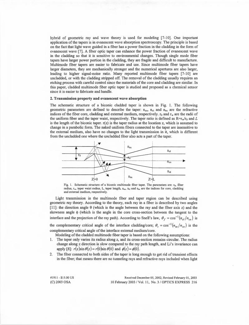
The schematic structure of a biconic cladded taper is shown in Fig. 1. The following geometric parameters are defined to describe the taper: Dco, nc1 and nex are the refractive indices of the fiber core, cladding and external medium, respectively. r0 and rw are the radii of the uniform fiber and the taper waist, respectively. The taper ratio is defined as R=rwlr0 and L is the length of the biconic taper. r(z) is the taper radius at the location z, which is assumed to change in a parabolic form. The naked uniform fibers connected to the taper are insensitive to the external medium, also have no changes to the light transmission in it, which is different from the uncladded one where the uncladded fiber also acts a part of the taper.
: -.
Zf> Z~L
Fig. 1. Schematic structure of a biconic multimode fiber taper. The parameters are: r0, fiber radius, rw, taper waist radius, L, taper length, llco, 11c1 and Dex are the indices for core, cladding and external medium, respectively.
Light transmission in the multimode fiber and taper region can be described using geometric ray theory. According to the theory, each ray in a fiber is described by two angles [11]: the direction angle 0 (which is the angle between the ray and the fiber axis z) and the skewness angle <I> (which is the angle in the core cross-section between the tangent to the
interface and the projection of the ray path). According to Snell's law, 01 = cos-1(nc,/nc0
) is
the complementary critical angle of the interface cladding/core; Be= cos-1(nex/nc0 ) is the complementary critical angle of the interface external medium/core.
Modeling of the cladded multimode fiber taper is based on the following assumptions: 1. The taper only varies its radius along z, and its cross-section remains circular. The radius
change along z direction is slow compared to the ray path length, and Li's invariance can apply[8]: r(z)sin0(z)=r(O)sin0(0) and ¢(z)=¢(0).
2. The fiber connected to both sides of the taper is long enough to get rid of transient effects in the fiber; that means there are no tunneling rays and refractive rays included when light
#1911 - $15.00 us (C) 2003 OSA
Received December 05, 2002; Revised February 01 , 2003
10 February 2003 / Vol. 11, No. 3 / OPTICS EXPRESS 216
reaches the taper region and outside the receiving end. Light entering the taper will be in
the range of O :S B :S BI and O :S ¢ :S { .
3. All refractive rays get lost as radiations in the taper region and will not be considered. All the tunneling rays excited by the taper are guided through and will be counted.
n/2 3 5 rt/2
........ ~ 2 sin·•t
o....._ ___ 0 ,.._ __ 0 ... 2 __ e .... , __ e ...... - 0 ;
0r e. e 0
(a). Cladded multimode taper (b). uncladded multimode taper
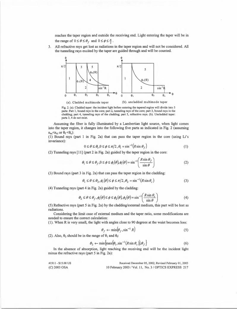
Fig. 2. (a). Cladded taper: the incident light before entering the tapered region will divide into 5 parts: Part l, bound rays in the core; part 2, tunneling rays of the core; part 3, bound rays in the cladding; part 4, tunneling rays of the cladding; part 5, refractive rays. (b ). Uncladded taper: parts 3, 4 do not exist.
Assuming the fiber is fully illuminated by a Lambertian light source, when light comes into the taper region, it changes into the following five parts as indicated in Fig. 2 (assuming llex<I1c1 or 0r<0c): (1) Bound rays (part 1 in Fig. 2a) that can pass the taper region in the core (using Li's invariance):
0 :SB :S B1,0 -5: ¢ -5: ,r/2JJi = sin-1(Rsin B1 ) (1)
(2) Tunneling rays [11] (part 2 in Fig. 2a) guided by the taper region in the core:
(2)
(3) Bound rays (part 3 in Fig. 2a) that can pass the taper region in the cladding:
B1 -5:B-5:B2 ,¢1(B)-5:¢-5:1t/2,B2 =sin-1(RsinBJ (3)
(4) Tunneling rays (part 4 in Fig. 2a) guided by the cladding:
B2 -5: B-5: B1 ,¢i (B)-5: ¢-5: ¢i(B),¢2(B) = sin-i(R ~in 8c) (4) smB
(5) Refractive rays (part 5 in Fig. 2a) by the cladding/external medium, this part will be lost as radiations.
Considering the limit case of external medium and the taper ratio, some modifications are needed to ensure the correct calculation: (1). When R is very small, the light with angles close to 90 degrees at the waist becomes loss:
B1 f-- min(B1 ,sin-1 R)
(2). Also, 02 should be in the range of 01 and 0r:
B2 f-- min~ax(B1,sin-1(RsinBJ}o1 }
(5)
(6)
In the absence of absorption, light reaching the receiving end will be the incident light minus the refractive rays (part 5 in Fig. 2a):
#1911 - $15.00 us (C) 2003 OSA
Received December 05, 2002; Revised February 01, 2003
10 February 2003 / Vol. 11, No. 3 / OPTICS EXPRESS 217
I - 1l . 2 8 le' l1r/2 . 0 0 . 2 ;/v-/LL.J,1, taper - 8 sm I -
82 ~(e)sm cos sm y,uc;u'f' (7)
The evanescent wave power for a ray in a uniform fiber with core radius r0 and cladding index Ilc1 is expressed as [7]:
rJ(B,¢)= Anc1 tanBsinB (S)
2.nn!iro sin2 8c~sin 2 Bc -sin2 8sin2 ¢ At each point z, only parts 3 and 4 contribute to evanescent wave in the external medium since parts 1 and 2 are shielded by the cladding; so the power fraction of the evanescent wave is expressed as:
e1(z)~(8,z) /91(z)~(9,z) rJ(z)= J J q(8,¢,z)sinBcosBsin 2 ¢dfll¢ J J sinBcosBsin 2 ¢dfll¢ (9)
81(z)~(8,z) 0 0
where 8 ( ) . -1 r0 sin 81 fJ ( ) . -1 r0 sin 82 1 z = sm ~ , 2 z = sm ( ) ,
7\ZJ 7 Z (10)
( ) . _1 Rr0 sin B 1 ( ) . _1 Rr0 sin Bc
¢>i. B,z = sm ( ) . ( ) , </Ji B,z = sm ( ) . ( ) rzsmBz rz~nBz (11)
Note cj> 1(8) and cj>2(8) are taken as rr/2 when the value in the sin·1 function in Eq. (11) is greater than 1.0. Just as indicated in Fig. 2, cj> 1(0) and cj>2(8) include the flat 1t/2 part.
The total absorbance is the integration of Eq. (9) along the taper [7]:
A= CrrJ(z)dz. (12)
where C is the absorption coefficient of the solution. For uncladded taper, only parts 1 and 2 have evanescent wave absorption, and r0 is the
radius of the core. The calculation can be performed in a similar way [7].
3. Numerical results
1.36 1.38 1.4 n.,.
1.42 1.44 1.46
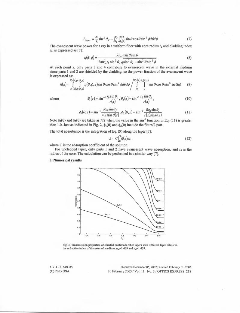
Fig. 3. Transmission properties of cladded multimode fiber tapers with different taper ratios vs. the refractive index of the external medium, 11co=l.469 and llct=l.459.
#1911 - $15.00 us (C)2003 OSA
Received December 05, 2002; Revised February 01, 2003
10February2003/Vol. ll, No.3/0PTICSEXPRESS 218

The transmission output of the taper vs. the refractive index of the external medium is calculated according to Eq. (7) and is shown in Fig. 3. The following data are used: nc0=1.469, nci= 1.459 and the intensity is normalized to the uniform fiber output. For large taper ratio, or small tapering, there is a region with 100% transmission, which means that for the external medium in that region, all light into the taper cladding will be recollected back to the fiber without any loss. When the index of the external medium is close to the cladding, part of light gets lost through radiation. If the refractive index of the external medium falls in the range between the cladding and core, light output will be stable since all light entering the cladding region becomes radiation; however, the light bound in the core is not affected. On the contrary, for uncladded multimode taper, the light output will approach zero when nelt approaches nc0
since the cladding is not present.
0.035--~--~---------~-~- -~
0.03
0.025
j 0.02
i >,
f 0.015 G)
0.01
0.005
R=0.1
500 1000 1500 2000 2500 3000 3500 4000 Position z:µm
Fig. 4. Evanescent wave energy fraction distribution along z. The power is normalized to the power in the core and cladding at each point. n.,.,=l.469, ~l.445, n...=l.330, i..=lµm, L=4mm, ro=62.5µm.
#1911 - $15.00 us (C) 2003 OSA
Received December 05, 2002; Revised February 01, 2003
10 February 2003 / Vol. 11, No. 3 I OPTICS EXPRESS 219

0.2 0.3 0.4 0.5 0.6 0.7 Taper Ratio: R
-+- Cladded ....,. Uncladded
0.8 0.9
Fig. 5. The absorbance vs. the taper ratio for cladded and uncladded fiber tapers. 11ex=l.330, 11co=l.469, Dci=l.445, )..=I.Oµm, L=4mm, ro=62.5µm for cladded tapers and r0=31.25µm for uncladded tapers. C is assumed to be 1 in the calculation.
The evanescent wave distribution along the taper is calculated according to Eq. (9-11) and is shown in Fig. 4, and the following data are used: 11c0=1.469, 11c1=1.445, flex=l.330, A.=lµm, L=4mm, r0=62.5µm, and the radius distribution of the taper is assumed to be parabolic:
r(z) = 4 r0 (1- R Xz - L/2 )2 + Rr0 • Similar results can be obtained for uncladded fiber tapers, L
except that the power fraction is larger than the cladded one with the same taper ratio. The absorbance can be obtained using integration of the power fraction along z according
to Eq. (12) and the results are shown in Fig. 5 for tapers with different taper ratios. The sensitivity increases when tapering increases. Compared to uncladded tapers, the sensitivity increases slower, especially in the small R region; for example, uncladded taper with R=0.2 could be about 5 times more sensitive than the cladded one.
Though the sensitivity of cladded tapers is lower, it has a higher mechanical strength since the strength is proportional to the waist area of the taper according to Hooke's law. For tapers with the same taper ratio, assuming r0 for cladded one is twice as large as the uncladded one, the mechanical strength for bending or pulling will be four times as large as the uncladded one. Furthermore, by eliminating the process of removing the cladding, the possibility of producing defects in the taper region can be avoided, thus increasing the reliability and strength of the fiber taper.
The sensitivity of the taper could be enhanced using longer taper region. The numerical results for both cladded and uncladded are shown in Fig. 6. For tapers with the same taper ratio, the sensitivity will increase linearly with the taper length.
#1911 - $15.00 us (C) 2003 OSA
Received December 05, 2002; Revised February 01, 2003
10 February 2003 / Vol. 11, No. 3 / OPTICS EXPRESS 220

40~----.----,------.----,----~----.
1 ~ cladded I ..,._ uncledded
35
30
~ 25
I ~ 20
5'--------'-----'------'-----'------'---~ 4000 5000 6000 7000
z:µm 8000 9000 10000
Fig. 6. Absorbance vs. the taper length. 1..=l.Oµm, ro=62.5µm, 11cx,=l.469, n.:i=l.445, na=l.33, R=0.5 and taper profile is assumed to be parabolic. C is assumed to be 1 in the calculation.
Figure 7 shows the sensitivity of taper with different taper ratios to the refractive index of external medium. From the result, we can see the sensitivity depends strongly on the refractive index of the external medium. Generally, the sensitivity will increase when the external medium index increases since the energy fraction of evanescent wave gets larger. But if the refractive index of the external medium is close to the index of the cladding or the core, the sensitivity will drop, since the light loss in the cladding increases and light fraction that can experience absorption drops significantly as indicated in Fig. 3. This property is quite different from the uncladded multimode taper, whose sensitivity increases all the way with nex till it equals to llco·
25
20
10
O'-------'-----------'---.L_--'-------'---'-----'----'r::::::,,i'&--C> 126 1.28 1.3 1.32 1.34 1.36 1.38 1.4 U2 1.44
" .. Fig. 7. The absorbance vs. the refractive index of the external medium. Due to the power loss when the refractive index of the external medium is close to the cladding, the sensitivity drops. C is assumed to be 1 in the calculation.
#1911 • $15.00 us (C) 2003 OSA
Received December 05, 2002; Revised February 01 , 2003
10 February 2003 / Vol. 11, No. 3 / OPTICS EXPRESS 221

5. Experiments
Fig. 8. Multimode fiber taper fabrication system. The LD (Laser diode) and the PD (photo detector)laser diode (LD) and the photo detector (PD) are used to monitor the tapering process.
A taper sample with a taper ratio of 0.17 and a length of about 5mm was fabricated. A Coming standard multimode fiber was used for the taper fabrication. Its core diameter was 62.5µm, cladding diameter was 125µm, and numerical aperture was 0.268. The fabrication system [12] is shown in Fig. 8. First, about 5cm of the buffer coating was stripped off from the fiber by dipping into acetone solvent for several minutes and then cleaning using ethanol. One end of the fiber was secured on a mounting post and the other end was loaded with a weight of several grams to produce a pulling force. The fiber was slowly tapered using a torch or micro-furnace to heat the middle of the stripped fiber. The tapering process was monitored using a laser diode and a photo detector. After the taper was made, the profile of the taper was measured using a microscope, and it might not be symmetric due to the one-sided pulling process.
Experiments with the taper were conducted using the setup shown in Fig. 9. A uniform multimode fiber was used as a reference to eliminate the source intensity variation with time. A halogen lamp was used to serve as a white light source that covers the wavelength region from 400nm to 1200nm. The fiber taper was secured with epoxy in a copper U-channel.
Ll L2
S~~.~t::=:::: taper 1
~ Ref~•::] Ir--,# Spectrometer IA · LJ
Fig. 9. Setup of experiment, LI, L2, L3, L4 are lenses, the light source is a white light Halogen lamp, which covers the wavelength region from 400nm to 1200nm.
Two test samples were prepared for the absorption measurement. Sample 1 was a solution of 20ml 20% dimethyl sulfoxide (DMSO) and 80% deionized water (DH20) with a refractive index of l.363(A=589.3nm). DMSO has a refractive index of 1.4780 and DH20 has a refractive index of 1.3333. The refractive index of the solvent of DMSO and DH20 varied linearly with the concentration, following the Lorentz-Lorentz law, which covered a refractive index range from water to the fiber core. The sample was transparent in the white light spectrum. Sample 2 was a 20ml DMSO solvent with the same concentration as sample 1 but with a O.lmmol laser dye IR-140 dissolved in. The laser dye had a broad absorption band from 500nm to 900nm with a peak absorption wavelength of 823nm. The addition of the laser
#1911 - $15.00 us (C) 2003 OSA
Received December 05, 2002; Revised February 01, 2003
10 February 2003 / Vol. 11, No. 3 / OPTICS EXPRESS 222
dye did not change the refractive index of the solvent. Transmission property could be verified using a series ofDMSO solvent samples with different refractive indices.
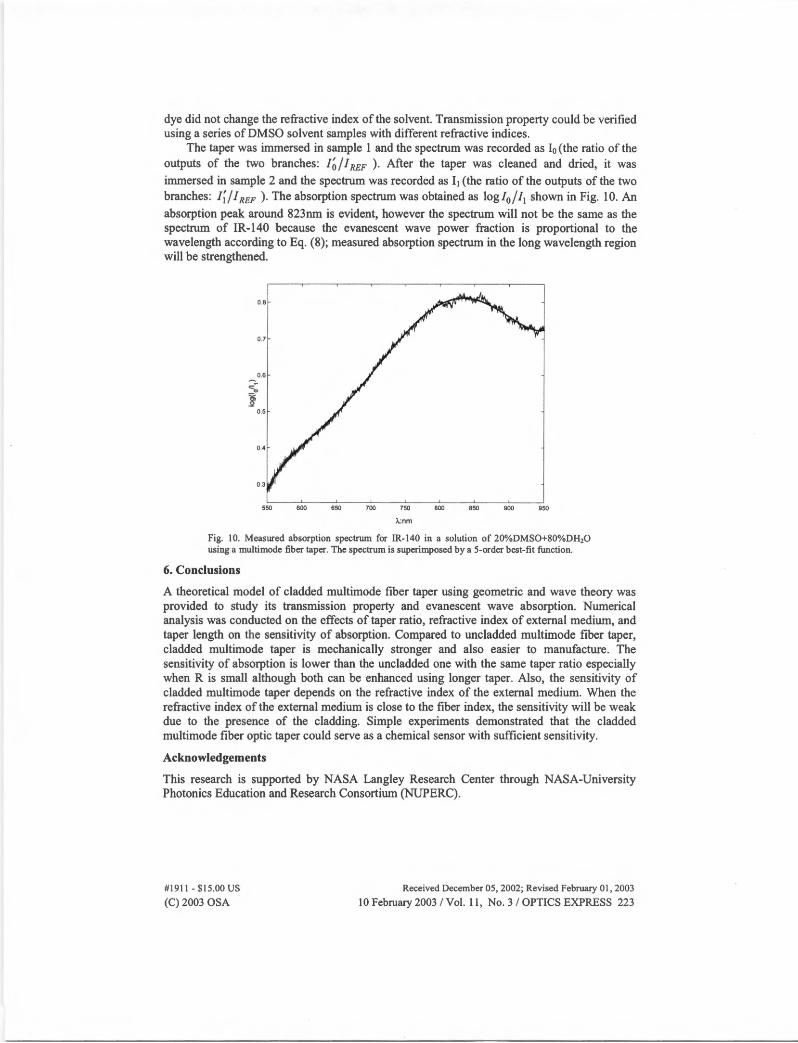
The taper was immersed in sample l and the spectrum was recorded as I0 (the ratio of the outputs of the two branches: /~ / J REF ) . After the taper was cleaned and dried, it was immersed in sample 2 and the spectrum was recorded as 11 (the ratio of the outputs of the two branches: 1;/ I REF ). The absorption spectrum was obtained as log/0/ 11 shown in Fig. 10. An absorption peak around 823nm is evident, however the spectrum will not be the same as the spectrum of IR-140 because the evanescent wave power fraction is proportional to the wavelength according to Eq. (8); measured absorption spectrum in the long wavelength region will be strengthened.
0.6
~ j
0.5
0.4
0.3
550 600 650 700 750
).:nm
800 850 900 950
Fig. JO. Measured absorption spectrum for IR-140 in a solution of 20%DMS0+80%DH20 using a multimode fiber taper. The spectrum is superimposed by a 5-order best-fit function.
6. Conclusions
A theoretical model of cladded multimode fiber taper using geometric and wave theory was provided to study its transmission property and evanescent wave absorption. Numerical analysis was conducted on the effects of taper ratio, refractive index of external medium, and taper length on the sensitivity of absorption. Compared to uncladded multimode fiber taper, cladded multimode taper is mechanically stronger and also easier to manufacture. The sensitivity of absorption is lower than the uncladded one with the same taper ratio especially when R is small although both can be enhanced using longer taper. Also, the sensitivity of cladded multimode taper depends on the refractive index of the external medium. When the refractive index of the external medium is close to the fiber index, the sensitivity will be weak due to the presence of the cladding. Simple experiments demonstrated that the cladded multimode fiber optic taper could serve as a chemical sensor with sufficient sensitivity.
Acknowledgements
This research is supported by NASA Langley Research Center through NASA-University Photonics Education and Research Consortium (NUPERC).
#1911 - $15.00 us (C) 2003 OSA
Received December 05, 2002; Revised February 01 , 2003
10 February 2003 / Vol. 11 , No. 3 / OPTICS EXPRESS 223