transmittal of dewatering and excavation … · 2006-09-13 · 144 1-401.5 transmittal of...
TRANSCRIPT

144 1-401.5
TRANSMITTAL OF DEWATERING AND EXCAVATION EVALUATION PROJECT
RAMP AND PAD EXCAVATION OF WASTE PITS I AND 3 TREATABILITY STUDY ADDENDUM - PROJECT SPECIFIC PLAN FOR THE
09/25/95
DOE-I 538-95 DOE-FN EPAS
REPORT -85- I d a
Department of Energy Fernaid Environmental Management Project
P. 0. Box 398705 Cincinnati, Ohio 45239-8705
(513) 648-3155
SEP 2 5 1995 DOE-1538-95
Mr. James A. Saric, Remedial Project Director U.S. Environmental Protection Agency Region V - 5HRE-8J 77 W. Jackson Blvd. Chicago, IL 60604-3590
Mr. Tom Schneider, Project Manager Ohio Environmental Protection Agency 401 East 5th Street Dayton, OH 45402-291 1
Dear Mr. Saric and Mr. Schneider:
TRANSMllTAL OF DEWATERING AND EXCAVATION EVALUATION PROJECT
PAD EXCAVATION OF WASTE PITS 1 AND 3 TREATABILITY STUDY ADDENDUM - PROJECT SPECIFIC PLAN FOR THE RAMP AND
This letter formally transmits the Department of Energy, Fernald Area Office (DOE-FN) Treatability Study Addendum entitled "Project Specific Plan for the Ramp and Pad Excavation of Waste Pits 1 and 3". This Project Specific Plan (PSP) is an addendum to the Dewatering Excavation and Evaluation Project (DEEP) Treatability Study.
This letter and the enclosed plan formally advises The U.S. Environmental Protection Agency (U.S. EPA) and the Ohio Environmental Protection Agency (OEPA) of the decision to proceed with the DEEP Phase 4 as enunciated in the DEEP Treatability Study Work Plan Addendum.
DEEP is a Post Record of Decision (ROD) Operable Unit (OU) Treatability Study designed to evaluate waste dewatering and excavation techniques that will be implemented during remediation of the OU1 waste pits. The DEEP project consists of four phases. In October 1994, geotechnical testing of soil borings and correlation of Standard Penetration Tests and Cone Pentrometer Tests (Phase 11, was completed. In March of 1995, the "wet excavation" (Phase 2 ) was completed. Phase 2 consisted of excavating a total of 7 test areas and removing 15 cubic yards of waste from each of Waste Pits 1, 2, and 3. A portion of the excavated material was archived for future treatability investigations; the remaining waste was returned t o the pit of origin. Following Phase 2, "Dewatering"
- i
Page 2
(Phase 3) was completed in August 1995. Phase 3 consisted of installing a series of wells in Waste Pits 1 and 3 and performing comparative well tests and pumping methods to determine if installing a well dewatering system ig a cost effective way to improve excavation conditions.
DEEP has now reached a point where field mobilization for the "dry excavation" (Phase 4) is in the planning stages. DOE-FN intends t o expand Phase 4 slightly to include a ramp and pad in Waste Pit 1, which is identified in the enclosure. The driving factor behind this expansion is the fact that OUl's full-scale remediation is set t o begin in Waste Pit 1. It is therefore essential t o construct this ramp and pad so that waste material conditions may be fully characterized and this subsequent information utilized during design and full-scale excavation.
In addition to the ramp and pad change, it has become apparent that due t o the size of the Phase 4 excavations the lined containment berm as described in the original DEEP Treatability Study Work Plan, cannot be maintained. The labor and capital cost of constructing the outer berm is much greater than the silt fencing containment described in enclosure one. Also, the size of stockpile would necessitate operating the tracked equipment on top of the plastic sheeting thereby eliminating its containment value. Instead, the above mentioned silt fencing will be used in support of the excavation grade to maintain run-off within the waste pit's contamination boundary.
While these berm containment and excavation methods were not in the original plan for the DEEP program, the DOE-FN believes that this approach represents the safest, most prudent, and cost-effective way t o obtain the required design information.
If you have any questions regarding this submittal, please contact John Hall at (513) 648-3118.
Sincerely,
FN:Hall Johnny W. Reising Fernald Remedial Action Project Manager
Enclosure: As Stated
l 4 g & .. .. .
Page 3
cc wlenc:
G. Jablonowski, USEPA-V, 5HRE-8J D. S. Ward, GeoTrans S. McClellan, PRC AR Coordinator, FERMCO
cc w/o enc:
K. Chaney, EM423 IGTN B. Skokan, EM423 IGTN Manager, TSPPIDERR, OEPA- COLUMBUS F. Bell, ATSDR R. Vandegrift, ODOH R.D. George, FERMC0/52-2 T. Hagen, FERMCOI65-2 C. Little, FERMC012 M. Yates, FERMCO/9

PROJIXT SPECIFIC PLAN
FOR THE
RAMPANDPAD EXCAVATION
OF WASTEPITS 1 AND 3
RI/FS WBS# 10.03.12
REVISION 0
SEPTEMBER 13, .I995

Restoration Management C o r p o h ~ n
FERNALD ENVIRONMENTAL
RESTORATION MANAGEMENT CORPORATION
CERCLA/RCRA UNIT 1 (CRU1)
PROJECT SPECIFIC HEALTH AND SAFETY PLAN FOR DEWATERING EXCAVATION EVALUATION
PROGRAM (DRY EXCAVATIONS)
SEPTEMBER 1995 REVISION 3
EMERGENCY PHONE NUMBER ON-SITE 648-6511 RADIO: "CONTROL"
APPROVALS:
Robert Fellman, CRUl Director Date r
Mikz Davis, FERMCO Health and Safety Officer Date
PROJECT SPECIFIC PLAN
FOR THE
RAMP AND PAD EXCAVATION
OF WASTE PITS 1 AND 3
RllFS WBS# 10.03.12
REVISION 0
SEPTEMBER 13, 1995
APPROVALS:
il $ A L A William A. Benson, Deputy Director
Q& -qkn- ...__
Danny F. Stropes, Project
.. ....
TABLE OF CONTENTS
Section
1 . 0
2.0
3.0
3.2
3.3
3.4
3.5
3.6
3.7
4.0
5.0
5.1
5.2
5.3
5.4
5.5
Title Paae
INTRODUCTION . . . . . . . . . . . . . . . . . . . . . . . . . . . . . . . . . . . . . . . . . . 1
.
PROJECT ORGANIZATION . . . . . . . . . . . . . . . . . . . . . . . . . . . . . . . . . 2
RAMP AND PAD EXCAVATIONS . . . . . . . . . . . . . . . . . . . . . . . . . . . . . 5
Excavation . Pit 1 . . . . . . . . . . . . . . . . . . . . . . . . . . . . . . . . . . . . . . . . 5
Excavation . Pit 3 . . . . . . . . . . . . . . . . . . . : . . . . . . . . . . . . . . . . . . . . 6
Stockpiles . . . . . . . . . . . . . . . . . . . . . . . . . . . . . . . . . . . . . . . . . . . . . 6 . Pit Water Handling . . . . . . . . . . . . . . . . . . . . . . . . . . . . . . . . . . . . . . . 7
Pit Water Sampling . . . . . . . . . . . . . . . . . . . . . . . . . . . . . . . . . . . . . . . 7
Equipment and Ancillary Items . . . . . . . . . . . . . . . . . . . . . . . . . . . . . . . 8 0 Decontamination . . . . . . . . . . . . . . . . . . . . . . . . . . . . . . . . . . . . . . . . 9
PITRECLAMATION . . . . . . . . . . . . . . . . . . . . . . . . . . . . . . . . . . . . . 10
SUPPORTING DOCUMENTATION . . . . . . . . . . . . . . . . . . . . . . . . . . . . 10
DEEP Treatability Study Work Plan . . . . . . . . . . . . . . . . . . . . . . . . . . . 1 1
Project Specific Health and Safety Plan . . . . . . . . . . . . . . . . . . . . . . . . 1 1
System Safety . . . . . . . . . . . . . . . . . . . . . . . . . . . . . . . . . . . . . . . . . 1 1
Radiological Safety . . . . . . . . . . . . . . . . . . . . . . . . . . . . . . . . . . . . . . 12
Data Management . . . . . . . . . . . . . . . . . . . . . . . . . . . . . . . . . . . . . . . 12
CRUl IMMPDFS.PSPISI13195 I

& ... i 4 4
TABLE OF CONTENTS (Continued)
0 Section - Title
5.6 Environmental Media Evaluation . . . . . . . . . . . . . . . . . . . . . . . . . . . . . 1 2
6.0 QUALITY ASSURANCE ................................... 12
6.1 Quality Assurance Requirements . . . . . . . . . . . . . . . . . . . . . . . . . . . . . 13
LIST OF ATTACHMENTS
.- -2
Attach. Title
ATTACHMENT A PROJECT SPECIFIC HEALTH AND SAFETY PLAN
*
ATTACHMENT B PROJECT SAFETY ANALYSIS REQUIREMENTS 0
ATTACHMENT C DATA QUALITY OBJECTIVE
ATTACHMENT D WASTE PIT EXCAVATIONS MAP
ATTACHMENT E ENVIRONMENTAL MEDIA SAMPLING PLAN

PROJECT SPECIFIC PLAN
FOR THE
RAMP AND PAD EXCAVATION
OF WASTE PITS 1 AND 3
RI/FS WBS# 10.03.12
REVISION 0
SEPTEMBER 13, 1995
APPROVALS: h* J $ - A L A William A. Benson, Deputy Director
Danny F. Stropes, Project M#ger
.... . .. ..--

1 4 4
TABLE OF CONTENTS
Section
1 . 0
2.0
3.0
. Title Paae
INTRODUCTION . . . . . . . . . . . . . . . . . . . . . . . . . . . . . . . . . . . . . . . . . 1
PROJECT ORGANIZATION . . . . . . . . . . . . . . . . . . . . . . . . . . . . . . . . . 2
RAMP AND PAD EXCAVATIONS ............................. 5
3.1 Excavation . Pit 1 . . . . . . . . . . . . . . . . . . . . . . . . . . . . . . . . . . . . . . . . 5
3.2
3.3
3.4
3.5
3.6
3.7
4.0
5 . 0
5.1
5.2
5.3
5.4
5.5
Excavation . Pit 3 . . . . . . . . . . . . . . . . . . . . . . . . . . . . . . . . . . . . . . . . 6
. . . . . . . . . . . . . . . . . . . . . . . . . . . . . . . . . . . . . . . . . . . . . Stockpiles 6
Pit Water Handling . . . . . . . . . . . . . . . . . . . . . . . . . . . . . . . . . . . . . . . 7
Pit Water Sampling . . . . . . . . . . . . . . . . . . . . . . . . . . . . . . . . . . . . . . . 7
Equipment and Ancillary Items . . . . . . . . . . . . . . . . . . . . . . . . . . . . . . . 8
Decontamination . . . . . . . . . . . . . . . . . . . . . . . . . . . . . . . . . . . . . . . . . 9
PIT RECLAMATION . . . . . . . . . . . . . . . . . . . . . . . . . . . . . . . . . . . . . 10
SUPPORTING DOCUMENTATION . . . . . . . . . . . : . . . . . . . . . . . . . . . . 10
DEEP Treatability Study Work Plan . . . . . . . . . . . . . . . . . . . . . . . . . . . 1 1
Project Specific Health and Safety Plan . . . . . . . . . . . . . . . . . . . . . . . . 11
System Safety . . . . . . . . . . . . . . . . . . . . . . . . . . . . . . . . . . . . . . . . . 1 1
Radiological Safety . . . . . . . . . . . . . . . . . . . . . . . . . . . . . . . . . . . . . . . 12
Data Management . . . . . . . . . . . . . . . . . . . . . . . . . . . . . . . . . . . . . . . 12
CRUIIRAMPDFS.PSPISI13195 I

TABLE OF’ CONTENTS (Continued)
Q
Section Title Paae
5.6 Environmental Media Evaluation . . . . . . . . . . . . . . . . . . . . . . . . . . . . . . 12
6.0 QUALITYASSURANCE ................................... 12
6.1 Quality Assurance Requirements . . . . . . . . . . . . . . . . . . . . . . . . . . . . 13
LIST OF ATTACHMENTS
Attach. Title
ATTACHMENT A PROJECT SPECIFIC HEALTH AND SAFETY PLAN
ATTACHMENT B PROJECT SAFETY ANALYSIS REQUIREMENTS
ATTACHMENT C DATA QUALITY OBJECTIVE
ATTACHMENT D . WASTE PIT EXCAVATIONS MAP
ATTACHMENT E ENVIRONMENTAL MEDIA SAMPLING PLAN
CRul /R4MPDFS.PsP/9/13/95

1.0 . INTRODUCTION
As part of the continuing Operable Unit 1 (OU1) Dewatering Excavation Evaluation Program (DEEP) Treatability Study field activities, OU1 proposes t o excavate a ramp and pad into each of Waste Pits 1 and 3. This excavation is an integral component.of the DEEP. The purpose of th i s Project Specific Plan (PSP) is to provide detailed information to support t he field and laboratory work associated with the DEEP project.
The project is divided into t w o separate ramp and pad excavations, one in Waste Pit 1, and one in Waste Pit 3. The purpose of these excavations is t o determine if the pit waste can support tracked construction equipment and t h e stability of the excavation side slopes. This information will assist in the overall was te pit excavation plan for final remediation. The Waste Pit Excavations Map (Attachment 0) shows t he ramp and pad excavation locations. The ramp locations were chosen for excavation into waste pit a reas where the waste has been shown by previous investigations t o be weak (Cone Penetrometer Tests) and where ground water infiltration (Wet Excavation) is minimal.
Upon completion of the dewatering program for Waste Pits 1 and 3 , the proposed ramps will be excavated in the s a m e locations a s the dewatering tests. The first ramp will be excavated in Pit 1 , then completely backfilled before the.Pit 3 ramp is started.
Each excavation will be initiated near the proposed location of t h e ramp. As excavation advances, the waste pit cap material will be segregated. Due t o the variation in thickness of cap material, segregation and separate stockpiling may not be feasible for Waste Pit 1 material. Waste Pit 3 c a p thickness is such that segregation of cap material will be possible.. As each excavation is advanced into the waste, the was te will be stockpiled adjacent t o the pit. Each excavation will be performed in such a manner tha t t he approximate dimension-and location of the ramp will be the focal point of t he excavation.
Since a ramp which possesses sufficient strength t o support heavy equipment is integral to this phase of DEEP, i f it is determined that the ramp will not be strong enough t o support heavy equipment, the ramp itself will be modified t o support heavy equipment. Such modification may consist of, but is not limited to, emplacement of concrete onto the ramp surface, or the removal of ramp waste material. replacement and backfilling of that material with higher. strength f i l l or aggregate.
CRUlIRAMPDFS.PSPI9I13195 0 1
.Following completion of the ramp and pad excavations, and conclusion of the information t o be gathered from the excavations, each pit excavation wil l be reclaimed in accordance with
the requirements of Section 4 of this PSP.
2.0 PROJECT ORGANIZATION
An Environmental Restoration Management Contract (ERMC) has been implemented a t the FEMP t o manage the site restoration activities; with Fernald Environmental Restoration Management Corporation (FERMCO), a wholly-owned subsidiary of Fluor Daniel, Inc., presently serving as the ERMC contractor t o DOE.
Primary FERMCO organizational responsibility for implementation of the OU 1 DEEP Treatability Study is OU1. Additional support will be provided by'matrixed personnel assigned t o OU1, and other FERMCO groups, and'subcontractors, who will provide personnel, expertise, and equipment t o assist with performance of all aspects of the Ramp and Pad Excavation project.
PROJECT PERSONNEL
Those personnel who fill key positions in the performance of the DEEP Treatability Study Ramp and Pad Excavation are as follows:
. .
Ooerable Unit 1 Deoutv Director (William Bensonl
The OU1 Deputy Director is responsible for coordinating assigned OU 1 activities including project performance, schedule, budget and resources. The OU 1 Deputy Director provides guidance and support to all OU 1 activities. Additionally, the Deputy Director provides project status information to senior management, client, and regulatory officials.
Ooerable Unit 1 Proiect Manaaer (Dan Strooesl
The OU1 Project Manager will provide guidance in the planning, preparation, and execution of this sampling and excavation event. Any and all proposed changes to this PSP must be cleared and approved by the OU1 Project Manager and Quality Assurance (QAI prior tu the preparation and execution of a variance t o this plan.
Ooerable Unit 1 Proiect Enaineer (Brad Catanachi
2

Responsible for ensuring that all field data quality objectives associated with the excavation field work are performed in a satisfactdry manner. The Project Engineer will also be responsible for preparing and maint.arning all field data documentation that provides a written record of excavation activities and measurements in the field.
Operable Unit 1 Construction Manaaer (Grea SteDhensl
Responsible for ensuring that all field work is initiated, performed and concluded in accordance with all applicable permits, DEEP project documents, and the PSP. Also responsible, in coordination with the Field Operations Lead, for the supervision of construction subcontractor personnel, and timely acquisition of all necessary field excavation equipment, and support items related t o performance of the excavation and reclamation. Responsible for transmitting construction-related changes in scope to the OU1 Safety Analyst for review against the established safety basis. Responsible for implementation of construction-related safety analysis commitments.
ODerable Unit 1 Field ODerations Lead (James T. Hevl
Responsible for ensuring the PSP is implemented correctly and efficiently in the field. Coordinates, with the OU1 Construction Manager, all excavation, soil and waste stockpiling .
and any required sampling activities in the field. Also obtains, in coordination with other support groups, all necessary work permits, and provides technical oversight of field personnel and subcontractors. Responsible for transmitting operations-related changes in scope to the OU1 Safety Analyst for review against the established safety, basis. Responsible for implementation of operations-related safety analysis commitments.
a
ODerable Unit 1 Health and Safetv Officer (Jack Craiaheadl
The Health and Safety Officer is responsible for the comprehensive OU1 Health and Safety Program. The Health and Safety Officer reviews and approves the DEEP Health and Safety Plan, which is specific to the proposed field activities, in accordance wi th FEMP policy, proper health and safety practices, and the SCQ. The OU1 Health and Safety Officer will coordinate with the Field Health and Safety Officer to assess unforeseen circumstances, from a health and safety perspective, and issue addenda to the Health and Safety Plan, as necessary. Responsible for transmitting programmatic safety-related changes in scope t o the OU 1 Safety Analyst for review against the established safety basis. Responsible for implementation of safety-related safety analysis Commitments.
*
CRUlIfUMPOFS.PSPI9Il3I95 a 3

I . Y :i
.s
ODerable Unit 1 Field Health and Safetv Officer (Mike Davis)
The Field Health and Safety Officer ensures that the Project Specific Health and Safety Plan is fully implemented during all field activities. The Field Health and Safety Officer will coordinate wi th the Project Manager to ensure that field activities are conducted in a manner which is consistent with the Project Health and Safety Plan. The Field Health and Safety Officer can request, verbally or in writing, that individual personnel be relieved of field duties for specific violations t o the Project Health and Safety Plan. The Field Health and Safety Officer will coordinate with the OU1 Health and Safety Officer t o assess unforeseen circumstances, from a health and safety perspective, and implement addenda to the Project Health and Safety Plan issued by the OU1 Health and Safety Officer. Responsible for transmitting field safety-related changes in scope t o the OU1 Safety Analyst for review against the established safety basis. Responsible for implementation of safety-related safety analysis commitments.
Ooerable Unit 1 Safetv Analvst (Elaine Blakelv)
The OU1 Safety Analyst is responsible for implementation of requirements for safety analysis into this project via hazard identification and accident analysis in accordance with all project safety-related documents, DOE Orders and FERMCO procedures.
Ooerable Unit 1 Qualitv Assurance Officer (Mike Hoael
The QA Officer is responsible for establishing and preparing QA requirements for the DEEP program, and ensuring that project QA requirements are met by field personnel. The QA Officer will perform or coordinate project audits and surveillance, as required.
Radioloaical Technicians (Ravmond Roseberrvl
Under supervision of Radiologicat Engineering and the Lead Radiological Technician, Radiological Technicians are responsible for the collection of radiological samples, verification of possible radiological contamination and decontamination of equipment, control of personnel ingress and egress to radiologically contaminated areas, documentation of radiological measurement results, and the provision of radiological monitoring equipment, in accordance with the approved Radiological Work Permit, and the PSP.
Environmental Field ODerations SamDlina Personnel
CRUl/RIIMPDFS.PSPISI13/95 4
1 4 4 Under supervision of the Environmental Field Operations (EFO) Section Manager, Mike Frank, or a designee, the sampling personnel are responsible for the collection, documentation, labeling, transport, and delivery of the environmental media samples t o be collected during this project. EFO sampling personnel will ensure that calibrated field screening equipment is available and will perform the actual screening of the samples. The sampling technicians shall be responsible for ensuring that the correct unique sample identifier is recorded on each sample label, Sample Collection Log and Site Wide Analysis RequestKustody Record. EFO will complete field validation checklists.
3.0 RAMP AND PAD EXCAVATIONS
Upon completion of dewatering activities in Waste Pits 1 and 3, Ramp and Pad Excavations will commence in the areas shown on the attached map. Excavation criteria shall be in accordance with OSHA Standard 29 CFR 1926, Subpart P.
3.1 Excavation - Pit 1
A trackhoe and tracked loader shall be used for the excavation into Pit 1. The first cut will be with the loader at approximately 6 inches in an attempt t o segregate the cover material from the waste material. Due to the thin layer of cover material on Pit 1, segregation of the cover material from the waste material may not be possible. The Construction Manager shall make a determination as to the advisability of segregating and stockpiling the cover material. a The following cuts will be at the discretion of the equipment operator since they will probably be into the waste. The depth of the excavation will be approximately 8 feet with 2H to 1V
side slopes, i f the slopes are not stable then they will be excavated to stable slopes. The ramp width will be 20 feet with a slope of 15%, these parameters may be adjusted depending on field conditions. The bottom pad will be approximately 30 feet in diameter.
Four deactivated dewatering wells are in the area of the excavation, these wells have PVC casing and will be excavated with the waste material.
Before the loader moves onto the waste, the hoe will perform a qualitative test by placing the bucket on the waste and applying downward pressure. The OU1 Field Health and Safety Officer, Construction Manager, Project Manager, and equipment operators will then assess the situation as to the safety of driving the loader on the exposed waste surface. Following this assessment, a determination will be made as to the advisability of driving the loader onto the exposed waste surface.
'
CRUl IR4MKIFS.PSP/9/13/95 a 5
I f it is determined that the surface is unstable, then excavation will be limited t o the material which the equipment can'reach from the ground surface. In this instance excavation will
proceed around the perimeter of the opening using a track hoe. '
3.2 Excavation - Pit 3
The excavation of Pit 3 shall be identical to Pit 1 with the following exceptions:
0 The excavation will be 12 feet in depth
0 The waste will have 2.5H t o 1V. slopes
The cover material in Pit 3 is approximately 8 feet in thickness; thus it should be easier to segregate than the 6 inch cover material in Pit 1
0
Approximately the top 5 feet of material in Pit 3 will be segregated from the remaining cover and waste material. When the excavation reaches a depth of approximately 8 feet, the trackhoe will perform a qualitative bearing test, as discussed in Section 3.1 , with assessments being made as t o the viability of the loader driving on the waste surface.
3.3 Stockpiles
Stockpiles will include t w o types,' these being cap material stockpiles, and waste material stockpiles. Project Safety Analysis Requirements (Attachment B) limit waste stockpiles t o a maximum volume of 535 cubic yards (yd3).
Stockpiles will be set back a minimum of 20 feet from the edges of the excavation. This 20 feet set back distance shall be maintained a t all times. Stockpiles may need t o be pushed back as the excavation proceeds. This will be accomplished with a tracked loader.
The stockpiles may be covered by tarpaulin and/or dust suppressants. may be used t o control windborne emissions. These measures will be a t the discretion of the Construction Manager, Health and Safety Manager, and Field Operations Lead.
I f tarpaulin is used, the tarpaulins will be placed onto.the stockpiles in such a manner that the stockpile is totally covered. Tarpaulin sides, ends and corners will be anchored in place with locally derived materials t o control possible waste particulate movement b y wind.
CRUlIPAMPOFS.PSPI9I13195 6

I f manufactured dust suppressants are used, the dust suppressant will be mixed in accordance with the manufacturer's recommendations for product use. Suppressant mixing will be done in a 3000 gallon fiberglass tank, and application will consist of spraying the suppressant onto the stockpile with a 2-inch water pump equipped with a hose and distribution nozzle. I f water is used as a dust suppressant, the water source will be FEMP process water. The method of application will be the same as with the manufactured dust suppressant.
In order t o control potential waste contaminated surface water runoff resulting from precipitation, silt fencing will be placed at the perimeter of the stockpiles where runoff is most likely t o occur. I f a significant accumuiation of waste material behind the silt fencing takes place, this waste material wil l be removed and placed back into the excavation.
3.4 Pit Water Handling
Surface water and near surface ground water which enters the pit excavations will be removed from the pit by the use of a sump pump which will be lowered in the excavation by the use of a trackhoe boom. A t the discretion of the Construction Manager, and Field Operations Lead, the temporary excavation of water management diversions may be required. Also, a t the discretion of the Construction Manager, in coordination wi th other project staff, small amounts of water in the excavation may not be removed, i f the amount or location of the water is determined to not hinder the excavation field activities or safety of field personnel.
Water removed from the excavationW will be temporarily stored in designated water storage tanks made available adjacent to the excavation. Upon completion of excavation activities, a t the discretion of the Project Manager, in coordination with other project staff, the stored water may either be removed and sent t o the Plant 8 water treatment system or else
. . reintroduced back into the excavation of origin.
3.5 Pit Water Sampling
A total of twenty (20) water samples will be collected during the project. Water samples are necessary in order to adequately characterize the water quality of the pit water for future treatability purposes at the FEMP Advanced Waste Water Treatment (AWWT) plant. Water 'samples are to be zrralyzed for the following parameters:
0 Chromium - hexavalent 8 Nitrates as Nitrogen
e CRU1/R4h4WS.PSP/S/13195 7
0 Chromium - total ' 0 Total Suspended Solids
' 0 Copper 0 Total Thorium
0 Nickel 0 Total Uranium
Water samples will be obtained from the designated water storage tank in which the pit water has been removed. A total of ten (10) water samples will be collected'from each excavation, unless lack of water prec!udes the collection of all proposed samples. I f there is a lack of water the Project Manager, in coordination wi th other project staff, may direct that a greater or lessor number of samples be taken, or any necessary changes t o the laboratory analysis parameters.
All water samples will be collected by FERMCO Environmental Division, EFO'staff technicians. Sample analyses will be performed. at the FERMCO Analytical Laboratory, unless otherwise airected by OU 1 Project Management staff. Sample collection, handling, documentation, chain of custody, and analyses will be conducted in accordance with applicable sections of the FEMP Sitewide CERCLA Quality Assurance Project Plan (SCQ). The Environmental Media . Sampling Plan (Attachment E) provides further information about the sampling activities.
3.6 Equipment and Ancillary Items
The following equipment and other ancillary items will be used to perform the field activities associated with the performance and completion of this project:
Equipment
0 0
0
0
0
0
0
0
0
0
0
.tracked loader trackhoe water pump JLG manlift generator dust suppressant and 3000 gallon fiberglass tank electrical cable video camera TV monitor water storage tanks plastic tarpaulin
8
0
0 silt fencing orange plastic hazard fencing and fence posts 144
Ancillary Items
0
0
0
0
0
0
0 '
0
0
0
Vehicles . .
Sampling equipment Sampling containers Sample preservatives Sampling coolers Temperature/pH/Conductivity meters (if needed) 'Radiological meters Photoionization detectors Surveying instruments (if needed) Decontamination equipment
3.7 Decontamination
When salvageable equipment and ancillary items are no longer needed for DEEP, they will be cleaned t o remove excess visible waste. Any gross contamination will be removed on site prior t o full decontamination a t the FEMP Decontamination Facility, where the equipment/items will be cleaned t o be authorized for free release off site.
All equipment that goes to the FEMP Decontamination Facility from the Contamination Areas surrounding Waste Pits 1 and/or 3 shall be labeled in such a way a s to indicate to the employees at the Decontamination Facility that Thorium-230 is the isotope of concern when surveying the equipment for free-release.
The FEMP will utilize a high-pressure s team and detergent mixture illustrated in FEMP SOP 55- C-101, "Operation of Steam Detergent Cleaner in the Decontamination and Decommissioning Building".
Following decontamination, a n evaluation of the potential for internal contamination of salvageable equipment will be made and the equipment will be radiologically surveyed to determine whether it can be authorized for free release off site. Equipment/items which cannot be decontaminated to the free release criteria will be containerized, labeled, and stored temporarily in the OU1 Waste Pit Area, or a t some other designated location a t the FEMP.
CAUl /PAMPoFS.PSP/9/13/95 a 9

4.0 PIT RECLAMATION
The sequence of reclamation will be the 3. As specified in this PSP, only one pit
reclamation of Waste Pit 1, followed by Waste Pit 0 will be excavated, tested, and reclaimed a t a time.
Following ramp and pad excavations the waste will be backfilled. The sludge may need t o be compacted with the tracked loader as it is backfilled, this will be at the discretion of the Construction Manager. During reclamation it may be necessary t o reintroduce pit pumpage water back into the excavation from the water storage tanks. If water is reintroduced into the pits, approximately one half of the water requiring disposal will be placed back into the pit after total depth in the excavation has been achieved, and the remaining water will be placed back into the pit after approximately one half of the excavated waste has been backfilled into the pit.
After waste backfilling, the cap soil material will be backfilled onto the waste surface, with
the possible exception of Waste Pit 1, where segregation and stockpiling of the cap soil material may not be feasible. Once approximately one half of the cap soil material has been placed onto the waste surface, and it has been determined that the surface is sufficiently stable t o support heavy equipment, the tracked loader will be used t o evenly distribute the cap material. Following this, backfilling of -the cap soil material will continue until all stockpiled cap material has been backfilled. Then the excavation surface will be graded as necessary to fill/grade any topograph/c low/high areas. The completed surface will be graded t o conform t o the approximate original surface contours of the excavation location prior t o surface disturbance.
The zi;!?ed surface will be reseeded and straw mulch will be used to control erosion and assist with seed germination.
I f , after a period of time, subsidence depressions which are determined t o be sufficiently severe enough t o warrant a safety hazard are noted, these depressions will be backfilled using locally derived uncontaminated soil material, and the surface reseeded and mulched.
5.0 SUPPORTING DOCUMENTATION
Ramp and Pad Excavation project supporting documents provide the basis .for safely and efficiently performing the necessary work. Specific requirements which govern performance of the work are addressed in the following documents:
10 e.

l l Q Q && ..: 5.1 DEEP Treatability Study Work Plan
OU1 DEEP activities are addressed in the treatability study work plan for the project. This document, titled "Operable Unit 1 Dewatering Excavation Evaluation Program (DEEP) Treatability Study Work Plan, Revision O", is dated April 1995.
Specific information about the ramp and pad excavation phase of DEEP is presented in Section 5 of this PSP. This document is available for review in OU1. .
5.2 Project Specific Health and Safety Plan
The Project Specific Health and Safety Plan (PSHSP) defines and provides detailed information . about the following:
t
0 Levels of Protection 0 Personal Protective Equipment/Clothing 0 Personal Air Monitoring 0 Excavation "Competent Person" requirements 0 Industrial Hygiene related issues 0 Radiological Exposure related issues ,
0 Control Zones 0 Exposure Guidelines 0 Hazard Recognition 0 Emergency Response Procedures
The PSHSP for this project is included as Attachment A of this PSP.
5.3 .Systems Safety
Systems Safety aspects of the DEEP Ramp and Pad Excavation activities are addressed in the Auditable Safety Record (ASR) 93-0024, Addendum 2, and Integrated Preliminary Hazard Assessment, titled "Dewatering Excavation Evaluation Program (DEEP) Phases 2, 3, and 4. A copy of this document is on file within OU1.
' The ASR for the ;amp and pad excavation as5gns.a Hazard Category of 3 to the project. Specific safety analysis related requirements of the project are presented in Attachment B of this PSP.
11

5.4 Radiological Safety
A Radiological Work Permit will be obtained prior t o initiation of field work. This permit will be obtained from the FERMCO Radiological Engineering group. The permit will provide specific information about the personal protective, radiological monitoring, and radiation work related requirements of the project.
. .
5.5 Data Management
Data collected for this project shaii consist of qualitative observations, quantitative laboratory water sample analysis results, and visual observations. All data obtained are t o be used by OU1 for the purposes of treatability study and remedial design planning.
All excavations will be video recorded in order to document a permanent record of the project activities. The video camera used shall have the capability of presenting the date and time on the video image. Measuring scales (survey rod, rule) shall be available to provide a scale while video recording various characteristics of the excavation and materials encountered. Additionally, still photographs of some project activities may be taken. A manlift will be at times to properly photograph and create video records of the excavations and other project activities.
5.6 Environmental Media Evaluation
Due to the relatively short ? e m duration and extent of these excavations, minimal potential degradation of environmental media is anticipated. The ASR directs that perimeter air monitoring for paiticulate emissions from the excavations and adjacent stockpiles be performed for the duration of the field activities. Also, excavation and stockpileb) perimeter air monitoring for radon. will be conducted during the duration of the project.
Perimeter air monitoring of the areas to be excavated and the excavations themselves will be performed by FERMCO Environmental Media monitoring personnel, using mobile continuous air monitoring instruments.
6.0 QUALITY ASSURANCE
The primary objectives of the Quality Assurance/Quality Control (QA/QCI section of this plan relzte t o the coliectior! of field information and data sufficient to evaluate the waste pit
excavation testing to occur during the DEEP. Specific objectives cf this field sampling e f f w 3 y.

shall be designed, organized, and implemented in a manner which will optimize the collection of information which meets the DO0 (Attachment C) specified in this PSP. To ensure information is gathered in such a manner tha t D,QO goals are met, QA/QC measures will be used t o determine conformance with overall OU1 objectives.
The fundamental mechanisms used t o achieve these quality goals can be characterized a s planning, prevention, assessment, and correction. These components are further described a s follows:
0 Comprehensive up front planning, prior to project start, which provides sufficient details of the project work scope and planning to successfully achieve the project goals.
0 Prevention of defects in the data quality 'through planning and design, documented instruction and procedures, and careful selection and training of skilled, qualified personnel.
Quality assessment through program or regular audits and surveillance t o supplement continual informal review.
0
0 Permanent correction of conditions adverse t o quality objectives through a. close-looped corrective action system.
6.1 QUALITY ASSURANCE REQUIREMENTS
Surveillances of work processes and operations shall be undertaken t o assure quality of performance. Surveillances shall be performed by the Quality Assurance Officer assigned t o the DEEP Treatability Study. Surveillance activities shall encompass technical and procedure requirements, and may be conducted at any point in the project.
A t a minimum, one surveillance shall be conducted, consisting of monitoring/observing on- going project activity and work areas t o verify conformance t o specified requirements. Surveillance shall be planned and documented in accordance with Section 12.3 of the SCQ.
CRUl /RAMPDFS.PSP/9/13/95 a . 13
. ATTACHMENT A
PROJECT SPECIFIC HEALTH AND SAFETY PLAN
CRUl /RAMFUFS.PSP/9/13/95 0
a Restoration Management Corpomtion
FERNALD ENVIRONMENTAL
RESTORATION MANAGEMENT CORPORATION
CERCLA/RCRA UNIT 1 (CRU1)
PROJECT SPECIFIC HEALTH AND SAFETY PLAN FOR DEWATERING EXCAVATION EVALUATION
PROGRAM (DRY EXCAVATIONS)
SEPTEMBER 1995 REVISION 3
a EMERGENCY PHONE NUMBER ON-SITE 648-6511
RADIO: TONTROL"
APPROVALS:
Robert Fellman, CRUl Director Date
I I.. r- y [ ' I , I , l # - , L > \ \ \
tructionkafety aid Health Manager Date
/ 0 7- //- 7 3
MikZ Davis, FERMCO Health and Safety Officer Date
Section .
Page
1.0 INTRODUCTION . . . . . . . . . . . . . . . . . . . . . . . . . . . . . . . . . . . . . . . . . . . . . . . 1-1
1.1 WORK AREA CHARACTERIZATION . . . . . . . . . . . . . . . . . . . . . . . . . . . . 1-1
1.2 WORK DESCFUPTION . . . . . . . . . . . . . . . . . . . . . . . . . . . . . . . . . . . . . . 1-1
2.0 ORGANIZATION STRUCTURE AND KEY PERSONNEL RESPONSIBILITIES . . . . . . 2-1
2.1 MANAGER. CONSTRUCTION SAFETY & HEALTH . . . . . . . . . . . . . . . . . 2-1
2.3 C R U ~ PROJECT DIRECTOR . . . . . . . . . . . . . . . . . . . . . . . . . . . . . . . . . . . 2-1
2.4 DEEP PROJECT MANAGER . . . . . . . . . . . . . . . . . . . . . . . . . . . . . . . . . . 2-1
2.5 DEEP ASSISTANT PROJECT MANAGER . . . . . . . . . . . . . . . . . . . . . . . . . 2-1
2.6 FIELD OPERATIONS LEAD . . . . . . . . . . . . . . . . . . . . . . . . . . . . . . . . . . 2-1
2.2 DEEP HEALTH AND SAFETY OFFICER . . . . . . . . . . . . . . . . . . . . . . . . . 2-1
3.0 SITECONTROL . . . . . . . . . . . . . . . . . . . . . . . . . . . . . . . . . . . . . . . . . . . . . . . 3-1 3.1 Radiological Areas . . . . . . . . . . . . . . . . . . . . . . . . . . . . . . . . . . . . . . . . . 3-1
3.2 Exclusion Zones'. . . . . . . . . . . . . . . . . . . . . . . . . . . . . . . . . . . . . . . . . . 3-1
4.0 TRAINING . . . . . . . . . . . . . . . . . . . . . . . . . . . . . . . . . . . . . . . . . . . . . . . . . . . 4-1
4.1 fiAZARD COMMUNICATION . . . . . . . . . . . . . . . . . . . . . . . . . . . . . . . . . . 4-1
3.2 RECORDS . . . . . . . . . . . . . . . . . . . . . . . . . . . . . . . . . . . . . . . . . . . . . . . 4-1
4.3 VISITORS . . . . . . . . . . . . . . . . . . . . . . . . . . . . . . . _ . . . . . . . . . . i . . . 4-1
5.0 MEDICAL MONITORING AND SURVEILLANCE . . . . . . . . . . . . . . . . . . . . . . . . . 5-1
5.1 REQUIREMENTS . . . . . . . . . . . . . . . . . . . . . . . . . . . . . . . . . . . . . . . . . 5-1
5.2 RECORDS . . . . . . . . . . . . . . . . . . . . . . . . . . . . . . . . . . . . . . . . . . . . . . 5-2
6.0 HAZARD ASSESSMENT . . . . . . . . . . . . . . . . . . . . . . . . . . . . . . . . . . . . . . . . . 6-1
6.1 RADIOLOGICAL ISSUES . . . . . . . . . . . . . . . . . . . . . . . . . . . . . . . . . . . . . . 6-1
6.2 INDUSTRIAL HYGIENE ISSUES . . . . . . . . . . . . . . . . . . . . . . . . . . . . . . . 6-1
6.3 SAFETYISSUES . . . . . . . . . . . . . . . . . . . . . . . . . . . . . . . . . . . . . . . . . . 6 4
6.4NUCLEARSAFETY . . . . . . . . . . . . . . . . . . . . . . . . . . . . . . . . . . . . . . . . 6-6
DEEP-HSP Scpccmber 1995 Rev3 1

TABLE OF CONTENTS
Section
7.0 HAZARDCONTROL . . . . . . . . . . . . . . . . . . . . . . . . . . . . . . . . -
:. . . . . . . . . . . 7-1 7.1 ADMINISTRATIVE/ENGINEERING CONTROLS . :.. . . . .’ . . . . . . . . . . . . . . 7-1 7.2 PERSONAL PROTECTIVE EQUIPMENT/RESPIRATORY PROTECTION . . . . . 7-1
8.0 DECONTAMINATION . . . . . . . . . . . . . . . . . . . . . . . . . .. . . . . . . . . . . . . . . . . . 8-1 8-1
8-1
8.1
8.2
SITE DECONTAMINATION REQUIREMENTS
CHEMICAL DECONTAMINATION REQUIREMENTS
. . . . . . . . . . . . . . . . . . . . . . . . . . . . . . . . . . .
9.0 EMERGENCY/CONTINGENCY PLANS . . .. . . . . . . . . . . . . . . . . . . . . . . . . . . . 9-1
9-1 9.1 REPORTING . . . . . . . . . . . . . . . . . . . . . . . . . . . . . . . . . . . . . . . . . . . . 9.2 EVACUATION ROUTES/ACCOUNTABILITY . . . . . . . . . . . . . . . . . . . . . . . 9-2
9.3
9.4 EMERGENCY RESPONSE
EMERGENCY EQUIPMENT . . . . . . . . . . . . . . . . . . . . . . . . . . . . . . . . . . 9-2 9-2 . . . . . . . . . . . . . . . . . . . . . . . . . . . . . . . . . . .
10.0 CHANGES TO THE PSHSP . . . . . . . ’ . . . . . . . . . . . .
Attachments:
Attachment A. Project Specific Health and Safety Requirements Matrix
Attachment B. Personnel and Environmental Monitoring and Action Levels
Attachment C. FEMP Rally Points
Attachment D. Location of FEMP Medical Facility
Attachment E. Work Area Material Safety Data Sheets (MSDSs)
Attachment F. Work Area Map
Attachment G. OSHA and DOE Employees Rights Poster
Attachment H. Acknowledgement Form
a A- 1
B-1’ c- 1 D- 1 E- 1
F- 1
G- 1 H- 1
DEEP-HSP Scpumkr 1995 Rev3 .. 11

1.0 INTRODUCTION
The provisions of this Project Specific Health and Safety Plan (PSHSP) are to be used during the dry excavations CERCLA/RCRA Unit 1 (CRU 1) Dewatering, Excavation Evaluation Program (DEEP). Compliance with this plan is required of all personnel who enter the work area associated with this project.
All personnel entering the work area (Waste Pits land 3) will be required to be oriented on the requirements of this PSHSP and the Project Specific Health and Safety Requirements Matrix (PSHSRM) (Attachment A). All personnel must sign an Acknowledgement Form (Attachment H) stating they have been oriented on the requirements of this plan, understand, and will abide by the provisions of this plan. The form will be controlled by the Health and Safety Officer during the work and then forwarded to CRUl document control as part of the project files.
1.1 WORK AREA CHARACTERIZATION The Waste Pits were remote dumping sites. When active written procedures controlled input into the pits but it is acknowledge that uncontrolled material was put into the pits. Uncontrolled material reported to be put into the pits are forktruck, uranium derbys, and out dated lab chemicals.
'
A map of the DEEP work area is shown in Attachment F.
1.1.1 Waste Pit 1 The majority of materials placed in Waste Pit 1 were dry solids, including general sump sludge, depleted slag, trailer cake, depleted residues, graphite/ceramics, thorium waste, and uranyl ammonium phosphate (UAP) filtrate. Drums, some containing material, are known to be in the pit.
1.1.2 Waste Pit 3 The materials placed in Waste Pit 3 consisted of general sump sludge, raffinate, trailer cake, slag leach, water treatment sludge, and thorium wastes.
1.1.3 Sampling Data
General and personnel air monitoring for volatile organic compounds (VOCs) has been conducted during DEEP activities. During the dewatering phase of DEEP, a spot measurement of a well casing in waste pit 3 showed the presence of ammonia, but levels were below detection outside the casing. No concentrations of VOCs approaching regulatory limits has been found.
Airborne contamination and radon monitoring conducted during DEEP activities has shown no employee exposures above regulatory limits. Radon limits above 2000 pCYL were detected during the slurry testing activity on pit 2. The radon level was found inside the slurry tank.
1.2 WORK DESCRIPTION
1.2.1 Excavation at Pit 1
A trackhoe and tracked loader shall be used for the excavation into Pit 1. The first cut will be with the loader at approximately 6 inches in an attempt to segregate the cover material from the waste material. Due to the thin thickness of cover material on Pit 1, segregation of the cover material from
DEEP-HSP Sepmnber 1995 Rev3 , 1-1

the waste material may not be attempted. The Construction Manager shall make a determination as to
The following cuts will be at the discretion of the equipment operator since they will probably be into
the advisability of segregating and stockpiling the cover material.
the waste. The depth of the excavation will be approximately 8 feet with 2H to 1V side slopes, if the slopes are not stable then they will be excavated to stable slopes. The ramp width will be 20 feet with a slope of 15%, these parameters may be adjusted depending on field conditions. The bottom pad will be approximately 30 feet in diameter.
Four deactivated dewatering wells are in the area of the excavation, these wells have PVC casing and will be excavated with the waste material.
Before the loader moves onto the waste, the hoe will perform a qualitative test by placing the bucket on the waste and applying downward pressure. The OU1 Field Health and Safety Officer, Construction Manager, Project Manager, and equipment operators will then assess the situation as to the safety of driving the loader on the exposed waste surface. Following this assessment, a determination will be made as to the advisability of driving the loader onto the exposed waste surface.
If it is determined that the surface is. unstable, the excavation will proceed around the perimeter of the excavation using a track hoe.
1.2.2 Excavation at Pit 3
The excavation of Pit 3 shall be identical to Pit 1 with the following exceptions:
0
0
The excavation will be 12 feet in depth
The waste will have 2.5H to 1V slopes
0 The cover material in Pit 3 is approximately 8 feet.in thickness: thus it should be easier to segregate than the 6 inch cover material in Pit 1
Approximately the top 5 feet of material in Pit 3 will be segregated from the remainins cover and waste material. When the excavation reaches a depth of approximately 8 feet, the trackhoe will perform a qualitative bearing test, as discussed in Section 3.1, with assessments being made as to the viability of the loader driving on the waste surface.
1.2.3 Stockpiles
Stockpiles will be set back a minimum of 20 feet from the edges of the excavation. This 20 feet set back distance shall be maintained at all times. Stockpiles may need to be pushed back as the excavation proceeds.
The stockpiles may be covered by tarpaulin and/or dust suppressants may be used to control windborne emissions. These measures will be at the discretion of the Construction Manager, Health and Safety Manager, and Field Operations Lead.
DEEP-HSP Scptanber 1995 Rev3 1-2
If tarpaulin is used, the tarpaulins will be placed onto the stockpiles in such a manner that the stockpile is totally covered. Tarpaulin sides, ends and corners will be anchored in place with locally derived materials to control possible waste particulate movement by wind.
If manufactured dust suppressants are used, the dust suppressant will be mixed in accordance with the manufacturer's recommendations for product use. Suppressant mixing will be done in a 3000 gallon fiberglass tank, and application will consist of spraying the suppressant onto the stockpile with a 2- inch water pump equipped with a hose and distribution nozzle. If water is used as a dust suppressant, the water source will be the FEMP potable water supply. The method of application will be the same as with the manufactured dust suppressant.
In order to control potential waste contaminated surface water runoff resulting from precipitation, silt fencing will be placed at the perimeter of the stockpiles where runoff is most likely to occur. If a significant accumulation of waste material behind the silt fencing takes place, this waste material will be removed and placed back into the excavation.
1.2.4 Pit Water Sampling
4
Surface water and near surface ground water which enters the pit excavations will be removed from the pit by the use of a sump pump which will be placed in the excavation. At the discretion of the Construction Manager, and Field Operations Lead, the temporary excavation of water management diversions may be required. Also. at the discretion of the Construction Manager, in coordination with other project staff, small amounts of water in the excavation may not be removed, if the amount or location of the water is determined to not hinder the excavation field activities or safety of field personnel.
All excavation water removed from the excavation(s) will be temporarily stored in designated water a storage tanks made available adjacent to the excavation. Upon completion of excavation activities, at the discretion of the Project Manager, in coordination with other project staff, the tanked water may either be removed and sent to the Plant 8 water treatment system or else reintroduced back into the excavation of origin.
1.2.3 Entering excavation for data collection
After completion of the excavation, 'monitoring for volatile organic compounds, radon and radiation may be conducted. Entry into the excavations would be based on stability of the excavation floor and walls. Final approval for personnel entering into the excavation is up to the HSO.
a DEEP-HSP September 1995 Rev3 1-3
2.0 ORGANIZATION STRUCTURE AND KEY PERSONNEL RESPONSIBILITIES
2.1 MANAGER, CONSTRUCTION SAFETY & HEALTH - Daryl Milis. Responsible for the oversight of activities in construction safety and health. Jack Craighead is the alternate for Daryl Mills for this project.
2.2 health and safety programs. Acts as the single point of contact for all environmental, safety, industrial hygiene, fire and radiological issuedconcern. Jack Craighead is the alternate for Mike Davis for this project.
DEEP HEALTH AND SAFETY OFFICER - Mike Davis. Responsible for maintaining DEEP
2.3 CRUl PROJECT DIRECTOR - Robert T. Fellman. Responsible for providing direction toward the development of the PSHSP and for providing signature approval to the' final document. William Benson is the alternate for Robert Fellman for this project.
2.4 DEEP PROJECT MANAGER - William M. Benson. Responsible for overall project performance. Reviews project plans, evaluates project against budget. and schedule, and coordinates activities with the client. Dan Stropes is the alternate for William Benson for this project.
2.5 DEEP ASSISTANT PROJECT MANAGER - Gregory W. Stephens. Responsible for assisting the project manager with project reviews, budgets, and schedules. Provides technical oversight of field operations and will direct excavation activities. William Benson is the alternate for Greg Stephens for this project.
2.6 FIELD OPERATIONS LEAD - James T. Hey. Coordinates field activities, obtains work permits, and provides oversight of field personnel. Greg Stephens is the alternate for James Hey.
DEEP-HSP SVmber 1995 Rev3 0 2- 1

i ..
3.0 SITE CONTROL
144
The following work areas will be established or encountered during the activities associated with DEEP.
3.1 Radiological Areas
Excavations will be performed inside a Radiological Contamination Area. Entrances to and perimeters of radiological areas will be defined by yellow snow fencing. All radiological areas will be identified by signs having the standard radiological symbol, the trifoil, on a yellow background.
. . The following areas will be encountered:
0 Controlled Area 0 Radioactive Material Area 0 Fixed Contamination Area 0 Soil Contamination Area 0 Contamination Area 0 High Contamination Area
The following areas may be created during excavation:
0 Airborne Radioactivity Area
. Radiological areas are established based on the contamination levels in Attachment B.
3.2 Exclusion Zones An exclusion zone is any area, room or enclosure where the activities being conducted present an additional safety hazard and requires additional PPE or training. The Exclusion Zone for excavation will be the radiological controlled area.
DEEP-HSP S c p m b c r 1995 Rev3 0' 3- 1
. 144 4 .-
4.0 TRALNIN G
All personnel conducting work associated with DEEP, inside the Rad Contamination Area. are to be Radiological Worker I1 (Rad 11) trained.
Additional training requirements specific to each task to be performed are outlined in the PSHS-W (see Attachment A).
4.1 HAZARD COMMUNICATION
4.1.1 Material Safety Data Sheets
MSDSs for site materials determined to present a hazard for work covered by this PSHSP are included in Attachment E. Additional MSDSs are available through the FERMCO HSO.
4.1.2 Job BriefingslSafety Meetings
A pre-workkick off safety meeting will be conducted by the FERMCO HSO with the DEEP Project Manager and project participants. This meeting will satisfy the requirements for the PSHSP safety briefing.
All personnel involved in this project shall be given a PSHSP safety briefing prior to receiving .authorization to begin work. This PSHSP safety briefing shall include review of this PSHSP and PSHSRM.
As a minimum, safety meetings shall be held weekly. The safety meetings will be conducted by the Field Operations Lead or designee. Written documentation detailing the briefings and attendance sheets will be maintained as part of the project. File copies shall be forwarded to the FERMCO HSO for review.
Whenever a revision or change is made to the PSHSP, or a change is made to existing work activities, the change shall be reviewed with project workers at a job briefing and documentation of the briefing and attendance shall be maintained as pan of the project file.
4.2 RECORDS Documentation of training classes, craft/operator certifications, and equipment operator experience records from sources other than the FEMP shall be submitted to the FERMCO HSO for review and approval.
4.3 VISITORS
A visitor to the work site covered by this PSHSP is defined as anyone coming to the work site with the sole purpose of observation or viewing the activity in progress (hands-off inspection). Visitors are not allowed to operate equipment, perform manual labor or supervise work activity.
Visitors that are Radiological Worker I1 trained are to be oriented ta the work site by:

Shall contact the site supervisor for briefing on the current site activities and the associated hazards Wear a Thermoluminescent Dosimeter (TLD) radiation badge and view the Visitor Orientation Video. Wear the required PPE specified on the posted FERMCO Work Permit.
Visitors (not Rad 11 trained) entering radiological contamination area shall:
Receive authorization from the Manager of Radiological Control and the FERMCO HSO. Be escorted by a person who has all the required training for the area to be toured. Wear a TheEsluminescent Dosimeter (TLD) radiation badge and view the Visitor Orientation Video. Briefing on this PSHSP and active permits Shall contact the site supervisor for briefing on the current site activities and the associated hazards Wear the required PPE specified on the posted FERMCO Work Permit.
4-2

5.0 AlEDICAL AiONITORING AND SURVEILLANCE
5.1 REQUIREMENTS
All personnel will be required to participate in the FEMP medical monitoring program, except for visitors and vendor services representatives on site for short durations. If examinations are to be conducted by medical personnel other than FEMP personnel, prior authorization relative to protocols and a list of providers must be obtained from the FEMP Medical Depamnent.
Medical monitoring requirements specific to each task to be performed are included in Attachment A.
Employees who receive radiopharmaceuticals or become pregnant are to report this information to the .FERMCO Medical Services Depament.
Employees in the following certification programs are required to have medical certification to perform their duties: ' , .
0 0
0 0
5 . I ..
DOT driver Respirator user Forklift operator Heavy Equipment operator
1 Bioassay Requirements
Personnel who must enter the work area for DEEP are required to participate in the FEMP bioassay program:
The following outlines the bioassay requirements for this project action.
0
0
0
0
e
0
Baseline urine samples will be required for all support personnel who are not active participants in the FEMP bioassay program.
Baseline fecal sampling is required for all project personnel who must access the.posted ContaminatiodAirbome Radioactivity Area at Waste Pits 1 and 3.
Follow-up fecal samples from all field personnel will be required for radiological incidents involving personnel contaminations, or when radiological conditions indicate a potential for inhalation or ingestion of thorium-bearing residues.
All personnel will be required to participate in the periodic urine sampling program. submit incident urine samples, and report to the In-vivo facility for whole-body counting when directed by the Medical Department and/or Radiological Control personnel.
All participants will submit a final "completion of campaign" urine sample after the project is finished.
Incident initial (end of shift) and post (start of next shift) urine samples will be required upon the occurrence of any airborne or personnel contamination event.
DEEP-HSP Scptanber 1995 Rev3 0 5- 1

If any confirmed positive results occur, a 24-hour follow-up sample will be initiated by Dosimetry for the affected individual.
5.1.2 Invivo Requirements
Personnel who must enter the work area for DEEP are required to participate in the FEMP invivo program. Requirements of the program are an initial, annual and termination counts.
5.2 RECORDS
The FERMCO Medical Services Department shall maintain a copy of all medical records.
DEEP-HSP Scpt~tnber 1995 Rev3 5 -2

This section addresses the potential health, safety, and environmental hazards associated with the conduct of the activities covered by this PSHSP. a Potential hazards to workers may originate form the chemical, physical. radiological, and safety hazards .present in the project area.
6.1 RADIOLOGICAL ISSUES
Radiological analyses of the Wastes Pits indicate that the following radioisotopes are of primary concern:
Uranium and its daughters Thorium 230 (limiting isotope) Radon
Uranium is a radioactive material. and in its soluble forms. is highly toxic to the kidneys. Soluble uranium compounds such as uranyl nitrate. uranyl fluoride and uranyl acetate are absorbed through' the skin. Non-soluble forms of uranium, such as uranium octaoxide (black oxide), uranium dioxide (brown oxide), uranium tetrafluoride (green salt), and uranium trioxide (orange oxide) are not absorbed through the skin, but constitute a radioactive inhalation hazard to the lungs. Most of the uranium compounds found in the Waste Pits 1, 2, and 3 are of the non-soluble type.
Thorium is also a radioactive material which was deposited in the Waste Pits as mixed oxide (cold) raffinates. These raffinates are residues of the refinery processes and contain high levels of Thorium- 230. Thorium-230 is the main isotope of concern because of the ratio of thorium activity as compared to the uranium activity in this area.
Radon is a colorless. odorless. and very dense gas. I t is formed during the uranium and thorium decay chain. Radon is an inhalation hazard because it decays by alpha emissions. Radon deposited'in human lungs and has been linked to increased incidence of lung cancers.
6.2 INDUSTRIAL HYGIENE ISSUES
6.2.1 Chemical Hazards
Chemical hazards associated with waste pit 1 and waste pit 3 resulted from the waste streams which were dumped into these pits.
Chemicals in waste pit 1 include:
magnesium fluoride . uranium compounds
dewatered sludges with trace amounts of metal compounds including beryllium. cadmium and sliver organics in trace amounts including dichlorodifluoromethane, tirbutyl phosphate, and PCBs
DEEP-HSP Seprmber 1995 Rev3 a 6-1 '

Ammonium, calcium, potassium and sodium carbonates as well as calcium and magnesium oxides were used in the waste treatment process to neutralize acid solutions (e.g. nitric acid) and the resulting solids are present in the pit.
Skin or eye contact with the material and ingestion or inhalation of the dust is to be avoided. Inhalation of gases or organic vapors is not expected to be an issue due to their very low concentrations in the pit material however, brief, localized concentrations could be encountered.
Chemicals in waste pit 3 include:
Filter cake, sludges and wet slurries contaminated by arsenic, magnesium fluoride and uranium compounds Trace amounrs of metal compounds: barium, lead, beryllium, cadmium, copper, and silver Trace amounts of organics: pentachlorophenol and PCBs
Ammonium, calcium, potassium and sodium carbonates as well as calcium and magnesium oxides were used in the waste treatment process to neutralize acid solutions (e.g. nitric acid) and the resulting solids are present in the pit.
Skin or eye contact with the material and ingestion or inhalation of the dust is to be avoided. Inhalation of gases or organic vapors is not expected to be an issue due to their very low concentrations in the pit material however. brief, localized concentrations could be encountered.
Hazards associated with these chemicals are discussed below. . . . . . . .
6.2.1.1 Arsenic. Inorganic
Arsenic is a shell gray metal in its pure form. It is a human carcinogen and an acutely toxic poison if ingested. Soluble trivalent forms, such as arsenic trioxide. may cause skin and mucous membrane irritation. Acute inhalation effects are rare and chiefly inflammation. Chronic inhalation effects may include perforation of the nasal septum. weight loss. nausea. diarrhea. hair loss. skin discoloration/lcsions. and loss of sensation from peripheral nerves.
6.2.1.2 Barium, Soluble
Barium is a silver-white malleable metal in its pure form. Alkaline barium compounds may cause local irritation to the eyes, nose, throat and skin. Barium presents a hazard when ingested or inhaled. Acute exposure symptoms may include vomiting, diarrhea. irregular pulse and muscular paralysis. Chronic exposure to barium sulfate may lead to a benign pneumoconiosis.
6.2.1.3 Uranium
Uranium is a radioactive material. and in its soluble forms, is highly toxic to the kidneys. Soluble uranium compounds such as uranyl nitrate, uranyl fluoride and uranyl acetate are absorbed through the skin. Non-soluble forms of uranium, such as uranium octaoxide (black oxide), uranium dioxide (brown oxide), uranium tetrafluoride (green salt), and uranium trioxide (orange oxide) are not
DEEP-HSP S ~ p ~ ~ m b c r 1995 Rev3 6-2
absorbed through the skin, but constitute a radioactive inhalation hazard to the lungs. Most of the uranium compounds found in the waste pits I and 3 are of the non-soluble type.
6.2.1.4 Other Metals
Othe'r toxic metals present in the pit wastes included beryllium, cadmium, copper, lead and silver. These, and other metals present in lesser amounts from a toxicity standpoint, are not expected to present significant hazards as long as established controls measures for the other chemicals and radionuclides are followed.
Beryllium is a suspected human carcinogen. Acute inhalation exposure.to beryllium may cause a nonproductive cough, shortness of breath and some weight loss. Chronic inhalation exposure to beryllium may lead to respiratory symptoms, weakness, fatigue, and weight loss.
Cadmium is a suspected human carcinogen. Acute inhalation exposure to cadmium may include symptoms of irritation of the nose.and throat, delayed cough, chest pain, weakness and shortness of breath. Chronic inhalation expvsure may cause ulceration of the nose, emphysema and kidney damage. Ingestion of cadmium causes nausea. vomiting. diarrhea and abdominal cramps.
Contact with copper dusts can produce symptoms of irritation of the eyes. nose and pharynx and can effect the skin, liver. respiratory system and kidneys.
Lead is a toxin to the blood forming organs. Early symptoms of exposure may include loss of appetite, insomnia, irritability and muscle/joint pains, followed by anemia. Lead is also listed as a possible human carcinogen of the lungs and kidneys. Routes of entry of lead are inhalation and ingestion.
Symptoms of exposure to silver may include grey pigmentation of the skin and eyes. Also. exposure a to silver may lead to skin irritation and ulceration.
6.2.1.5 Fluoride Magnesium fluoride is a grayish white fine particulate inaterial uhich was produced as a by-product in the production of uranium metal. Fluorides may cause irritation to the eyes. skin or respiratory tract upon exposure. Symptoms of acute exposure may include salivation. nausea. vomiting, abdominal pain. fever. and labored breathing. Prolonged exposure may result in perforation of the nasal septum. Chronic effects include excessive calcification of the bones. ligaments and tendons.
6.2.1.6 Nuisance Particulates Much of the material in the pits (e.g. calcium. magnesium. potassium sodium compounds. soils. ect.) are classified as nuisance particulates. Nuisance particulates are inert dusts considered to be relatively harmless unless exposure is severe; therefore. nuisance particulates are not regulated by their chemical composition. Excessive exposure to even low toxicity dusts may cause skin, eye and upper respiratory tract irritation.
6.2.1.7 .Organics Organic compounds are a health concern because they are absorbed by the body and may cause tissue damage. nausea, dizziness and other central nervous system effects. Some are carcinogens. The
DEEP-HSP Scptmber 1995 Rev3 a 6-3
. - - ..

hazard associated with organic compounds varies based on the type of compound, the level of exposure, the length of exposure, and the route of exposure.
6.2.1.8 Ammonia Ammonia is an easily detectable pungent gas which is created by protein decomposition or reaction of a strong base with an ammonium salt. Ammonia forms a strong alkali solution in water, in mucous membranes, or on wet skin, and is highly irritating to the eyes, nose and upper respiratory tract. If irritation is ignored or elevated exposure persists, skin and eye burns and pulmonary edema may occur.
.
6.2.3 Temperature Extremes
6.2.3.1 Heat Stress Heat stress may affect personnel performing activities with or without protective clothing when working in high ambient temperatures. Plenty of water, use of cooling devices, rest breaks and careful attention by the supervisor shall.be used as control measures. Personnel shall become aware of symptoms of heat stress and be able to recognize these symptoms in oneself and in other workers. Symptoms of heat stress include: muscle cramps, fatigue, weakness, loss of coordination. nausea and in the later stages, hot dry skin (absence of sweating), delirium and seizures.
The FERMCO HSO or designee shall review heat stress recognition and prevention at a regularly scheduled safety meeting.
When ambient temperatures exceed 80"F, FERMCO IH shall be contacted to review and/or add control measures to minimize heat stress (i.e.. cool vests).
6.2.3.2 Cold Stress Tasks may be conducted when temperatures could present a potential cold stress hazard. Personnel shall become aware of symptoms of cold stress and be able to recognize these symptoins in oneself, and in other workers. The FERMCO HSO or designee, shall review the recognition and prevention of cold stress at a regularly scheduled safety meeting. A cold weather safety briefing will be required of all workers on this project.
During cold weather. special care should be taken to dress appropriately for anticipated weather conditions. Specific attention will be given to the hands and feet to prevent frostbite. Medicated skin lotions are provided in all restrooms at the FEMP and should be applied to face and hands to reduce changes of windburn and frostbite. Chap-stick or protective creams should be applied to lips to avoid chapping. When equivalent chill temperature drops below 0' F, FERMCO IH shall be contacted to review and/or add control measures to minimize cold stress. .
6.3 SAFETY ISSUES Safety is a top priority at the FEMP; accordingly, all employees are advised of their rights and responsibilities under the U.S. Department of Energy (DOE) Order 5483.1A and the Occupational Safety and Health Act. These rights and responsibilities are included as Attachment G.
6.3.1 Physical Hazards
6.3.1.1 Noise
DEEP-HSP September 1995 Rev3 6 4
Personnel in areas where noise levels exceed 85 dBA are required to utilize h m proteaion provided by their supervisor.
Noise levels exceeding 85 dBA may be created during operation of heavy equipment and portable power tools. If workers have'to raise their voice to be heard, noise levels may have exceeded 85 &A level. .
6.3.1.2 Lifting AI1 personnel should know their lifting limits and the proper way(s) to lift. The object to be lifted should be limited by factors such as the route and distance to be trave!&, the amount of time required and the center of gravity necessary to handle the load safely.
A worker shall not lit3 more than 50 pounds without assistance from another person or mechanical help.
6.3.1.3 Equipment Operation Safety The use of heavy equipment (drilling rig. backhoe, front end loader) on the Waste Pits may cause a possible sinking hazard due to the soft subsurface conditions. A pre-placement inspection along the anticipated route of travel shall be performed prior to movement to locate soft areas. It may be necessary to use a material such as "Unimat," timbers, or other similar material.
Follow these basic safety practices when woiking around heavy equipment. e M i z e personnel working around operating heavy equipment. e All mobile equipment shall be supplied with an electronic back-up alarm * All operators will be qualifizd to operate their machines.
Equipment will be inspected at the begiruling of each shift, prior to use, and the inspection results will be recorded on a daily check sheet to ensure that all safety equipment and devices are fully operational.
6.3.1.5 Excavation Activities Due to the inherent instability of land fills and given the wide variety of buried waste, special consideration mwt be given to operations requiring excavations-in the Waste Pits. - Tbe possibility of eocountering soft, unstable contents is high; therefore, ce+ pibut i~% W-W-td%+ -NO personnel shalt be allowed closer than 10 feet to the trench/excavation edge unless &- are adequately tied off or positioned on a boom-type manlift or the excav4on is sloped in zaonhce-witb 1926 subpart P.
a *
- -
Personnel will not be allowed to enter the pit untiI the excavation is completed, s t d i n g water removed and the pit floor determined to be stable. Stability of the pit floor will be determined by ability of excavation equipment to move about the pit.
Vibration of support equipment (portable lighting, generators) could contribute to the collapse of pit walls. Location of this equipment is to be kept at least 10 feet away from the trench walls.
6.3.1.7 Sanitation An adequate supply of potable water shall be provided on the site. The containers used to dispense
. drinking water are to be capable of being tightly closed and equipped with a tap. Containers used to . .. -_-L__L_. . - A - : - s _ ._ -____ .__ _ _ _
~ __ -___ . _._ -___ - .....- , , _ _ _ _ .....,: ~ .... -..: ...- ..... ..._. - * t,: !-.: : i e 7 p ; T2Fkfx! 2nd "Of E?Pd m r any other i w m . A:: Zr'&np . - c a DEEP-HSP scpcmba 1995 R-3 6-5
wafer locations within a radiological controlled area are to be reviewed by FERMCO Radiological Control and IH personnel prior to use.
Adequate washing facilities shall be provided to employees engaged in operations where hazardous substances are encountered.
6.3.2 Fire Protection Excavations will be monitored by FERMCO for volatile compounds. Should an explosive atmosphere be detected, all work will stop and FEIUiCO Fire and Safety be contacted.
6.3.3 Drum and cylinder handling The potential exis; O h a t intact containers (drum, cylinders) will be found during excavation of the Waste Pits. Should this OCCUT, the Field Operations Lead and the FERMCO HSO shall be contacfed. Unless orieiltation of the container does not allow safe removal, the container will be removed from the excavation and over-packed.
. . 6.4 NUCLEAR SAFETY
No criticality safety concerns exist with disturbance of the pit material because of the low uranium concentration in the Waste Pits.
For pumping activities, it is not credible that water removed from these pits during the dewatering activities could contain enough U235 to cause an inadvertent nuclear criticality during precipitation of the heavy metals prior to processing the water.
The gravitational settling done as part of the waste reslurry and pumping3est may lead to an increase in concentration of uranium in the settled sludge. Sludge samples will be collected from the tank and analyzed for uranium to determine if a hazard exist.
6-6
L;r 1 4 4
7.0 HAZARDCONTROL
7.1 ADMINISTRATIVE/ENGINEERING CONTROLS When feasible, engineering controls will be used to control physical, chemical, and radiological hazards. Engineering controls anticipated to be used during the work covered by this PSHSP include:
. Containment of radiologically contaminated equipment Control of trench exposures by use of manlift and distance limitations. Control of environmental insults by the use of wetting agents, tarps, drainage control and area monitoring.
The following administrative controls shall be used to control physical, chemical and radiological hazards during project activities:
PSHSP for CRUl DEEP
FERMCO Work Permits.
0 FERMCO Auditable Safety Record
0 FERMCO Integrated Preliminary Hazard Assessment
7.2 PERSONAL PROTECTIVE EQUIPMENT/RESPIRATORY PROTECTION
The level of personal protective equipment (PPE) and respiratory protection to be worn by field personnel involved with task activities is defined on an activity basis in Attachment A. When the PPE required by the matrix states that anti-Cs are required for work in contamination areas. anti-Cs include: disposable protective clothing with booties, rubber shoe covers and hood for dry work. disposable water resistant protective clothing with shoe covers and hood (i.e., Durafab Comfort Guard 200, Frharn Cool Suit or other approved materials) for wet work conditions. knee high rubber boots and latex or vinyl surgical gloves. Wrists and ankles shall be taped. The Field Operations Lead will be responsible for ensuring that all personnel are wearing the required PPE as specified by this PSHSP.
. . . . . . . a'
The levels of PPE and respiratory protection (PPE/RP) in the PSHSRM and the FERMCO Work Permits have been based on characterization data and regulatory requirements. Modification to the level of PPE/RP may be required based on field monitoring of conditions or changes to regulatory requirements.
The modification of PPE/RP level due to changes in safety or chemical hazards (non-radiological) may be conducted by the FERMCO HSO or IH Technician, for the hazard being controlled. changes are required. the following steps will be taken:
When
1 . Contact the HSO and all other affected S&H Departments (Industrial Hygienists and IH Technicians. Radiological Engineering and Control) to determine if the change affects their controls.
DEEP-HSP Scprembcr 1995 Rev3 a 7- 1

2.. IH Technicians will complete a new PPE page of the FERMCO Work Permit and inform the FERMCO Permit Group.
3. The FERMCO HSO will change the PPE section of the PSHSRM.
The modification of the PPE/RP level due to changes in radiological hazards requires the following steps be taken:'
1. Consult with the Industrial Hygienist, Radiological Engineer, and the HSO.
2. Radiological Control shall document the changes by rewriting and reissuing the affected field FERMCO Work Permits.
3. The FERMCO HSO will change the PPE section of the PSHSRM.
All personnel working under this PSHSP are responsible for reviewing currently posted PPE/RP '
rcocuirements and adhering to those requirements. All personnel musf stay abreast of changing work area conditions and requirements. This will be facilitated by pre-job briefings, daily tailgate safety briefings. and weekly safety meetings.
DEEP-HSP S c p m b c r 1995 Rev3
. ..
7-2
8.0 DECONTAMINATION 0 8.1 SITE DECONTAMINATION REQUIREMENTS - FERMCO will provide instructions for decontamination which may consist of steam cleaning, dry brushing or washing with appropriate liquids.
Area decontamination of chemical and radioactive materials should be done with a combination of scraping to remove the gross contamination at the control point to Waste Pits and the pressure spraying of the heavy equipment at the Waste Pit 6 concrete decontamination pad.
8.1.1 Personal Decontamination Requirements Upon leaving the work area, workers will be instructed by the Radiologid Control Techiciam (RCTs) and/or Industrial Hygiene 0 technicians on how to frisk, in which containers to place disposable and launderable PPE, and what to do if personal radioactive contamination is detected.
Personal contamination on the skin, or on the inner personal company-issued clothing, shall require contact with Radiological Control Technician immediately. Detection of a count rate above background with an appropriate field portable monitoring instrument "frisker" should alert personnel of possible contamin2tion.
Contaminated personnel may have to initiate a bioassay analysis for assessing internal radiation dose from possible inhalation, ingestion, or absorption of radioactive materials. The need to initiate a bioassay analysis and the scope of the analysis, will be determined by the FERMCO HSO with input from Radiological Engineering.
8.1.2 Equipment Decontamination Requirements Equipment fcr !he decontamination of radiological hazards shall be kept available in the area su&unding the controlled areas (Contamination Reduction Zone). by a RCT prior to its removal from a radiologically controlled area.
Equipment must be monitored
Thorium-230 is a pure alpha particle emitter; therefore, each piece of equipment must be smeared and - counted on a special instrument before it can be "free released." . -
8.2 CHEMICAL DECONTAMINATION REQUIREMENTS In case'of body contact with a hazardous material, PPE shmld be doffed'with extreme caution to prevent cross contamination of the skin. Contaminated inner clothing shall be removed and the affected body area shall be washed thoroughly (1 5 minctes minimum) in a safety shower or eye bubbler. Involved personnel shall report immediately to Medical Services or summon aid (phone 648-651 1 or radio Control) as needed. Notification shall be made to the appropriate supervisor as soon as possible.
Questions concerning chemical contamination and potential exposure should be directed to FERMCO Industrial Hygiene at 648-585 1.
a DEEP-HSP Scpmbcr 1995 Rev3 8- 1

9.0 EMERGENCYKONTINGENCY PLANS
Ambulance
Hospital
Fire
Security
Emergency Response
Assistant Emergency Duty Officer (AEDO)
9.1 REPORTING
648-6511 Control Control Ch7
648474914444 Control Ch7 202
9.1.1 EMERGENCY NUMBERS- ON-SITE EMERGENCIES
NAME Construction Site
FEW TELEPHONE NO.
9.1.2 SITE NOTIFICATION PROCEDURES All emergencies shall be reported to the Communications Center to ensure rapid response. A means to report an emergency shall be available at all work locations whenever personnel are working. This may be accomplished by one of the following methods:
'
Phone - 648-651 1 Radio to "Control"
Any injury, no matter how minor. shall be reported to Medical Department for evaluation and treatment. The injured employee shall be accompanied to the Medical Department by the supervisor in charge or designee. The CRUl Project Director and the FERMCO HSO shall be notified as soon as possible after the injury has occurred.
Employees working on-site will be notified of emergency conditions by the plantwide alarm system and by radio announcements. This announcement follows the sounding of the site alarm horn signal. 3-3.
9.1.3 What to Report The following are examples of emergencies that would justify calling and reporting an emergency:
Serious Injury Injury Complicated by Contamination ChemicallRadiation Release
0 Chemical Splash (Eye and Skin) Any Fire
0 Major Property Damage 0 Unusual Occurrence(s)
DEEP-HSP September 1995 Rev3 0 9- 1
When an emergency or abnormal condition is observed, personnel shall contact the Communications Center at extension 651 1 or via.radio (CONTROL) for on-site emergencies. You are to stay on the phone line until the dispatcher hangs up.
The following information must be given to the Communication Center operator:
Name Badge number Location where emergency has occurred Nature of the emergency Unusual conditions (smoke, vapors, odors) Current status of the emergency
9.2 EVACUATION ROUTES/ACCOUNTABILITY .
. Rally Point Accountability Should a situation require an emergency evacuation of the work area, all equipment should be turned off (if possible) and left ir, p ixe. On-site personnel should immediately proceed to the nearest established Rally Point (Raily h i n t #6 for waste pit area) as identified on the map found in Attachment C.
9.3 EMERGENCY EQUIPMENT
The Medical Department is staffed and equipped to handle most types of medical emergencies that would occur during a task. The medical facility is staffed with Emergency Medical Technicians (EMTs) and is equipped with an ambulance to transpon the injured person to the nearest off-site hospital should extended or specialized treatment be necessary.
The Medical Department is located at the east end of the first floor of the ES&H Building (Building 53). The location of the Medical Department and the most direct path to the facility from the work area can be seen in Attachment D.
A eyewash station with a drench hose for flushing the body is to be located at the work site.
9.4 EPJE?GENCY RESPONSE
The Emergency Response Team (ERT) will handle all on-site emergencies. Any request for emergency help should be requested by telephone (648-)6511 or on any radio frequency by calling "CONTROL."
9.4.1 Medical Emergencies
The Medical Department and emergency site ambulance shall serve as the first-aid person.
9.4.2 Fire Emergencies
During excavation. in the Waste Pits. tile potential exist that adverse chemical reactions could occur (i.e., fumes, smoke, fire. etc.). Should this occur, tke,Gperator will, backfill the excavation to stop
DEEP-HSP September 19% Rev3 9-2
tbe reaction. If.the operator judges that she is in imminent danger from fumes, smoke, OT spreading fire, s h e shall immediately vacate the equipment.
In either case. the omrator shall DrOceed to notify both the Field Operations Lead and tht FERMCO HSO. The FERMC'O HSO will wntact the Assistant Emergency Duty O f f e r (AEDO) and Emergency Response Team (ERT) (if necessay). Re-entry requirements will be determined by a joint decision of the CRUl Project Director and Health and safety representatives.
AI1 work sites shall maintain effedve CommUniCation to summon fire figbting assistance. Access to the work area shall be maintaiaed at all times to permit fire trucks and fire fighting crews to safely approach.
Only trained personnel shall attempt to operate any fire fighting equip= and only when the fire is clearly within the capati!ity of the bre fighting equipment. A fire extinguisaet is to be located at the waste pit control point.
The Emergency Response Team (ERT) will also respond to all on-site fire emergencies. For any fire emergency at FEW, call '(648-)6511.
9.4.3 Explosion Emergency When an explosion has occurred the following actions are to be taken:
0 Evacuateworkarea o 0 0 0 0 0
Proceed to the nearest rally point Render first aid to any injured personnel (if qualified) Instruct all persons in transit to avoid the work area and surrounding area Contact CONTROL by radio or phone (6511) Call for medical assistance if necessary Report to supervisor for accountability
- - .
- . .. .
.. , - .- - - _ _ . . - .. _. - . . . -
- - . , ='- . . ..,- 9.4.4 Chemical Emergency
_.. . . . . .- .. .. . . - - -. . ..
.. : .~ - . . _ - . . . _ _ _ _
F ' . - _ - . . . ~ .. ' -
- . d-;wi&. a-&-&& or *- --&all && &' affeded with clean water-for - h m + I5 &utes. Report to the Medical D e p w
All instances of personnel chemical co ntaminatiOn shall be &fled to Industrial Hygiene, the FERMCO HSO, Field Operations Lead and the AEDO.
L . . . - .
9.4.5 Radiological Emergencies
9.4.5.1 Releases Evacuate the release area. The supervisor in charge, AEDO, Radiological Control Technicians, and FERMCO HSO shall be notified of the release.
9.4.5.2 Personal Contamination Contamination should be avoided where possible by making minimum contact with the contaminant. All instances of personnel radiological contamination must be reported to Radiologicz' Control.

9.4.6 Weather Limitatiom/Adverse Conditions Any outside work will be suspended if warnings for high winds, lightnhg or tocMdos are sounded.
9.4.7 Accident Investigation Any injury or accident shall require the supervisor to complete an accident report. For injuries and illness, a 'Supervisors Report of Injury" shall be completed within 24 hours of the event and forwarded to the Medical Department services and to the Construction Contract Manager. Should a serious accideat/injury occur, the involved area should not be disturbed until approved by the FERh4Co Hso.
9.4.8 Uncover of unidentifiable iteams
If an unidenti&ble item is unwvered and appears to be leaking, off-gassing, or creating an immediately unsafe condition, personnel are to bacldill the excavation to stop the reaction. If the operator judges that she is in imminent danger from fumes, smoke, or spreading fire, s h e shall immediately vacate the equipment and contact site supervisor.
If an unidentifiable item is uncovered during any of the DEEP activities, and it appears to be in a stable condition, then an attempt will be made to identify it. An item will be considered identified when the OU1 Field Operations Lead, Health and Safety Lead for Field Operations, and the Radiologicd Control Field Lead Technician supporting DEEP agree on what it is.
If it cannot be identified, then work will stop and the Assistant Emergency Duty Officer (AEDO) will be rded in.
If the item is identified a an intact d m or cylinder, then the item will be removed, overpackd, and set aside. The AEDO will be contacted to deternine final disposition of the overpacked item.
If the item is identified as a solid metal item; then it may be removed, placed on the material stockpile, and covered with more material so it is not exposed to air, wind, or water. If an item is placed on the material stockpile, it->Till.be noted in the off-shie inspection schedule, and the inspector.
- . - . ., . 2 - - - .= .- . - . _ . . _ - - - .
- . w ~ d ~ ~ ? d i - t & - ~ g S a t ~ $ - - re@@$:cwer&i. - " . - . - -- --= 7 .: : .;- -__L;.:~~~~,=!._QE--~=.~--.,I r*
-.T+ _ - ... -. - - i. - - -
10.0 CHANGES TO THE PSHSP
rl,
This PSHSP for field activities is based on information available at the time of preparation. Provisions of this plan are to be reassessed quarterly by the FERMCO HSO or when conditions/events arise that require reassessment of health and safety issues. PPE requirements,including respiratory protection requirements, will be reevaluated when air sampling data are available, and changing trends in airborne levels are observed. Amendmentdrevisions of this PSHSP must go through formal review and approval by all departments included in the original review cycle.
For the purpose of ensuring that all personnel are informed of any changes in the scope of this PSHSP, CONTROLLED copies of this document shall be maintained by ES&H Document Control. Only essential personnel shall maintain controlled copies of this document. The following table is the list of personnel with the controlled copies of this PSHSP.
CRUl Project Director, Roben T. Fellman FERMCO Health and Safety Officer, Michael S. Davis DEEP Project Manager, Wiliiam M. Benson industrial Hygiene, Dave Jackson Industrial Hygiene Technicians, Jack Patrick Medical Department, Doran Christensen Fire Protection Manager, Steve Wentzel Radiological Permitting, Judy Hitt Work Site Copy, Jim Hey
0 DEEP-HSP September 1995 Rev3 10-1
ATTACHMENT A PROJECT SPECIFIC HEALTH AND SAFETY
REQUIREMENTS MATRIX

fi
0 L
I
P,
E
..e.
I 1
1
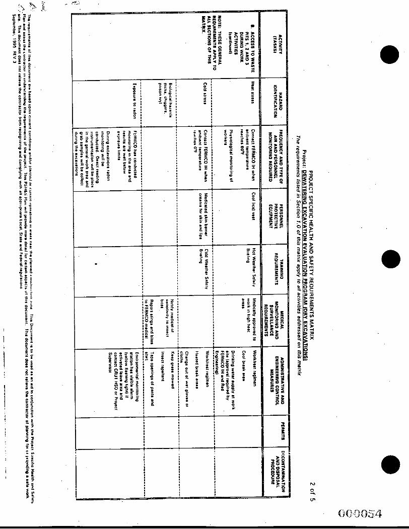
1
I ,
I i !
I I !
i
I I 1
I I I I
I 1
I
I I I I 1
I
! !
I I
1
' I
I I I I I
I I I
I I I
1 I I
I
I i

. .
Ln
L
3 . c7
I I I I I I I 1 I
. . I
Y
1 I I
I I
1 4 d
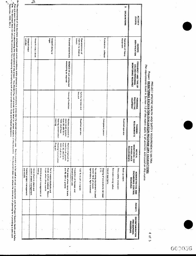

I i I I
I :
I t
i
-
ATTACHMEWB .
PERSONNEL AND ENVIRQNMENTAL MONITQRING AND ACTION LEVELS a
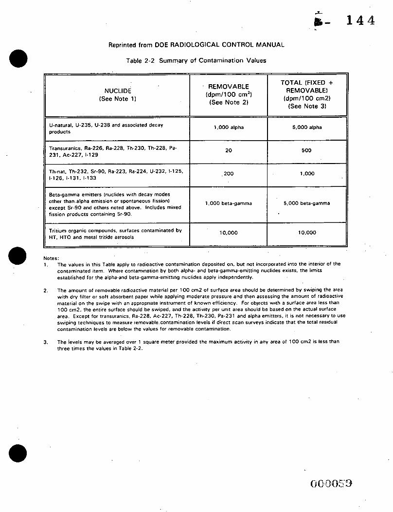
Reorinted from DOE RADIOLOGICAL CONTROL MANUAL
Table 2-2 Summ,ary of Contamination Values
NUCLIDE (See Note 1)
TOTAL (FIXED + REMOVABLE)
(dpm/lOO cm2) (See Note 3)
. REMOVABLE (dpm/lOO cm2) (See Note 2)
U-natural, U-235, U-238 and associated decay ILLts 1.000 alpha 5,000 .alpha
Transuranics, Ra-226, Ra-228, Th-230, Th-228, Pa- 231, Ac-227, 1-1 29
2 0 500
200 I Th-nat. Th-232, Sr-90, Ra-223, Ra-224, U-232, 1-1 25, ll 1-126, 1-131, 1-133 I 1.000
Beta-gamma emitters (nuclides with decay modes other than .alpha emission or spontaneous fission) except Sr-90 and others noted above. Includes mixed fission products containing Sr-90.
1,000 beta-gamma 5,000 beta-gamma
I Tritium organic compounds, surfaces contaminated by HT, HTO and metal tritide aerosols II 10,000 10,000
I I
Notes: 1. The values in this Table apply to radioactive contamination deposited on, but not incorporated into the interior of the
contaminated item. Where contamination by both alpha- and beta-gamma-emitting nuclides exists. the limits established for the alpha-and beta-gamma-emitting nuclides apply independently.
The amount of removable radioactive material per 100 cm2 of surface area should be determined by swiping the area with dry filter or soft absorbent paper while applying moderate pressure and then assessing the amount of radioactive material on the swipe with an appropriate instrument of known efficiency. For objects with a surface area less than 100 cm2. the entire surface should be swiped. and the activity per unit area should be based on the actual surface
2.
area. Except for transuranics. Ra-228, Ac-227, Th-228, Th-230. Pa-231 and alpha emitters, it is not necessary to use swiping techniques to measure removable.contamination levels if direct scan surveys indicate that the total residual contamination levels are below the values for removable contamination.
3. The ievels may be averaged over 1 square meter provided the maximum activity in any area of 100 cm2 is less than three times the values in Table 2-2.
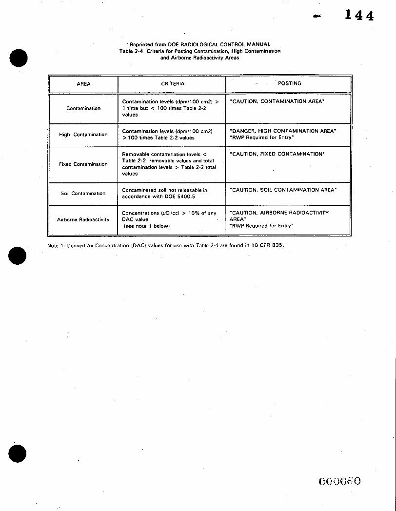
0
CRITERIA
1 4 4
POSTING AREA II Contamination levels (dpm1100 cm2) > 1 time but < 100 times Table 2-2 values
"CAUTION, CONTAMINATION AREA'
High Contamination
Contamination ll Contamination
High Contamination
Fixed Contamination
Soil Contamination
Airborne Radioactivity
Fixed Contamination
Soil Contamination
Airborne Radioactivity
' Reprinted from DOE RADIOLOGICAL CONTROL MANUAL
and Airborne Radioactivity Areas Table 2-4 Criteria for Posting Contamination, High Contamination
1
Contamination levels (dpml l00 cm2) > 100 times Table 2-2 values
Removable contamination levels < Table 2-2 removable values and total contamination levels > Table 2-2 total values
Contaminated soil not releasable in accordance with DOE 5400.5
Concentrations bCilcc) > 10% of any DAC value (see note 1 below)
'DANGER, HIGH CONTAMINATION AREA' 'RWP Required for Entry"
"CAUTION, FIXED CONTAMINATION'
"CAUTION, SOIL CONTAMINATION AREA'
"CAUTION, AIRBORNE RADIOACTIVITY AREA" "RWP Required for Entry"
. Note 1 : Derived Air Concentration (DAC) values for use with Table 2-4 are found in 10 CFR 835. 0

f
INDUSTRIAL HYGIENE PERSONNEL AND. ENVIRONMENTAL MONITORING ACTION LIMITS
MEASUREMENT
Organic vapors
Totai dust
Explosive gases
Ammonia
LEVEL
Detection to 25 ppm
>io% LEL
>10 ppm
. . .
ACTION
Use air purifying’ respirator
Contact FERMCO IH if > 10 ppm
Contact FERMCO IH ---- -----_-
Use air supplied respirator
Check engineering and administrative controls .
Obtain personal samples to characterize contaminant and concentration. Establish measurement methods, action levels, and actions for the wr??,zinant
Contact FERMCO IH
Use air purifying respirator
Check engineering and administrative controls
Obtain personal samples to characterize contamjnant and concentmiion; - meas;ien;ent- & --*- . - methods, action levels, and - - actiiortsfor the contaminant.
. . . . - . . .:
Contact FERMCO Fire and Safety -
Use air puriwing respirator
Contact FERMCO IH’ . - _ - Check engineering and administrative controls
Withdraw and reevaluate activities ---
1 4 4

. INDUSTRIAL HYGIENE PERSONNEL AND
ENVIRONMENTAL MONITORING ACTION LIMITS
LEVEL
>0.005 mg/m’
~ ~~
Detection to 10 ppm
> 2 5 ppm
> 1.25 mglm’
ACTION
Use air purifying respirator
Implement required training and medical surveillance, engineering, administrative and PPE requirements
Contact FERMCO IH
Check engineering and administrative controls .
~~~~
Withdraw and re-evaluate activities
Use air purifying respirator
Check engineering and administrative controls
Contact Industrial Hygiene
ATTACHMENT C FEMP RALLY POINTS
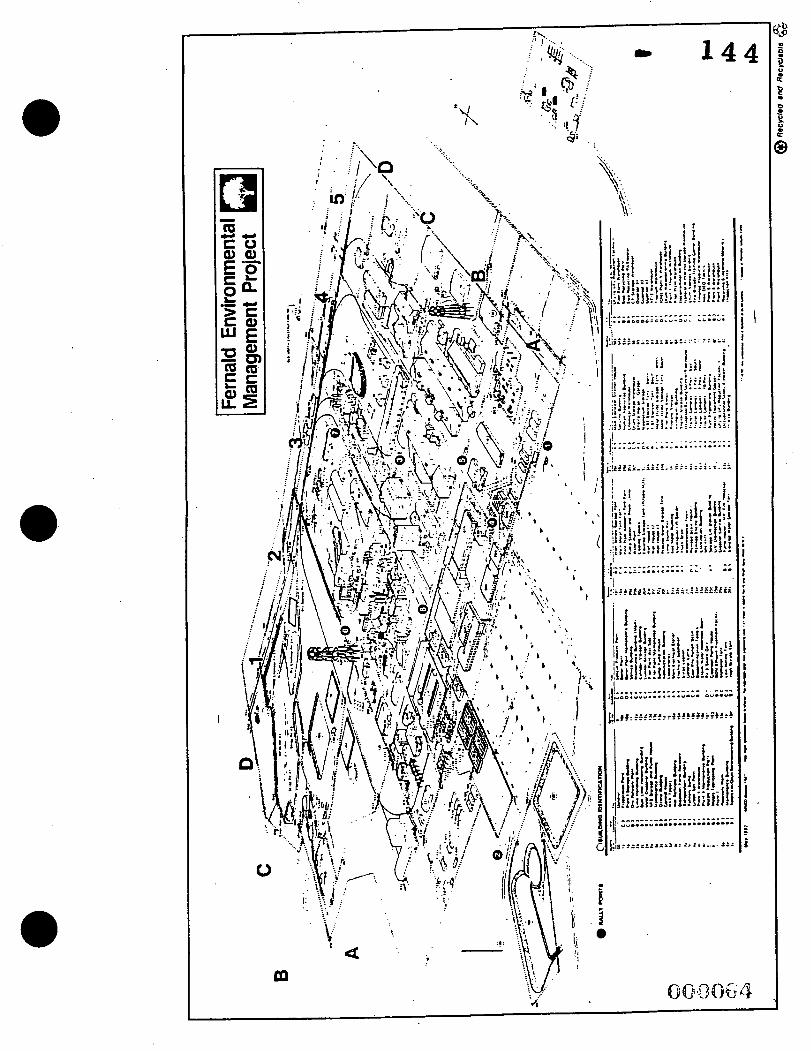
I
m
ATTACHMENT D LOCATION OF FEMP MEDICAL FACILITY

I
._..__. ~ ...... . . . . .
...."r.O..r..i...........
r -
Lt 1 4 4
ATTACHMENT E WORK AREA MATERIAL SAFETY DATA SHEETS
(MSDSs)

A T T N : S A F E T Y D I R E C T O R G A T E : 12/02/8d
7400 Y I L L E Y ROAD F E R N A L a OH 4 5 0 3 0 C 06117
W E S T I N t i i i O U S E H A T E A l & L S CCI OF OHIO C U S T j 9 3 9 7 b 8 P o 0 1 J 4-06117
R TE
R E V
C S .- O M 3 3 2 5 0 0 0
I f ' d S t STANDARDS, AND R E G U L A T I O N S Y A G r d E S I U H f L U I ) R I O E
ACGXH T L V - T d A 2 . 5 A G ( F ) / H 3 8 5 I N A 8 5 . 2 7 2 ~ 6 6 MSHA S T A N O A R D - A I R : T d A 2 0 s H G ( F ) / M 3 O T L J S * 3 9 L L 6 ~ 7 1 3SHA S T A N D A R O - A I R : TWA 2.5 H G ( F ) / N 3 fEKEAC 39~ , !3S40 ,74 NIOSH R E L 1 3 I N O R G A N I C F L U O R I O E S - A I R : T i A 2.5 MG(f)/M3 HHWR** 3 4 ( 1 S ) r
E P A T S C A C H E M I C A L I N V E N T O R Y , 1986 l7s.as
NS
C S .- O M 3 3 2 5 0 0 0
I f ' d S t STANDARDS, AND R E G U L A 1 1 0 ACGXH T L V - T d A 2 . 5 n C ( F ) / H 3 8 5 MSHA S T A N O A R D - A I R : T d A 20s HGC 3SHA S T A N D A R O - A I R : TWA 2.5 HG( N IOSH R E L 1 3 I N O R G A N I C F L U O R 1
E P A T S C A C H E M I C A L I N V E N T O R Y , 1986
Y A G r d E S I U H f L U I ) R I O E
l7s.as
ONLY S E L E C T E D R E G I S T R Y OF T O X I C E F F E C T S OF C H E Y I C A L S U B S T A N C E S ( R T E C S ) D A T A IS P R E S E N T E D HERE. SEE A C T U A L E N T k Y IN R T E C S FOR C O M P L E T E I N F O R M A T I C
A C U T E EFFECTS HAY 3E HARHFiJL B Y I N H A L A T X O N . I N G E S T X O N v OR S K I N A J S O R P T I O N o H A Y CAUSE I R R I T A r I O N o TO THE REST 3F 3 U R KNOWLEDGET THE C H E M I C A L * P H Y S I C A L , AND T O X I C O L O G I C A L PROPERTIES H A V E YOT BEEN THOROUGHLY INVESTIGATEDO
F XRS
A D D 1
T AI9 i t J CASE OF CG;JTACTI I M M E D I A T E L Y FLUSH E Y E S dITH C O P I O U S AHOUNTS OF WATEZ EOR AT LEAST 15 MINUTES. I N C A S c OF CONTACT. I M M E D I A T E L Y WASH SKIN ilIfH SOAP A N 0 COPIOUS AHOUNTS OF WATER. IF 1'4HALED. AEHOVE TO FRESH A I R - I F NOT b R E A T t i I N G GIVE A R T I F I C I A L RESPIRATION. I F 3 R E A T H I h ; G IS O I F F I C U L T I G I V E OXYuENo C A L L A P H Y S I C X A N o d A S H C O N T A t l I h A l E O C L O T H I N G 8 E f 3 R E REUSE. T 1 3 N A C
V O H I T I ! d G * ASDCMINAL P A I N , i E V E R . L A d U R E O B R E A T ~ I N G o F L U O R I D E i3N C REDUCE SERUM C A L C I U M L E V E L S P O S S I a L Y C A U S I N G F A T A L H Y P O C A L C E M I A - SRCL3&GE3 E X P O S U R E TO F L U O R I D E DUSTS. JAPORS 0;1 A I S T S R E S U L T S I N ? E ? F I Z ~ A T I ~ N 3F TdE NASAL S E P T U H o C H R O N I C EFFECTS i i r C L U O E EXCESSIVE C A L C ; F X C A l I O P i OF THE 3 0 N E S e L I G A M E N T S AND TENOONS.
I N f ZIRMA 1 I ON s r n ~ r m s of FLUORIDE OVEREXPOSURE .YAY IMLUDE sxIw.iroNI NAUSEA*
AN
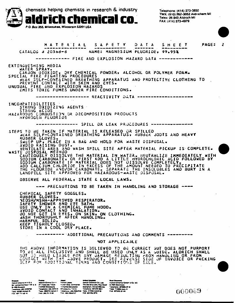
t@ Y
s . 4
chemists helping chemists in research 6 industry
aldrlcn cnemlcai co, Toieghm: (414) 273-385C Iwx: 1910) m-3052 AlQrtchem MI Tekx: 26 843 Aldrich MI fAX: {::e; 273-4919
.PACE: 2
C A T A L O G i3 203bd-d NAME: M A G N E S I U t 4 F L U O A I O E I '39095%
------------ F I R E AtiD E X P L O S I O N H A Z A R D b A T A ------------ E X T I ?iGU I S)i I N G M E 0 I A
S P E C I A L F I R E F I C r l T I N G PROCEDURES
UNUSUAL F I R E A t 4 0 E X P L O S I O N H A Z A R D S
r l A T E R SPRAY. C A R J O N O I O X I D E I 3 R Y C H E Y I C A L POWDER9 A L C O H O L OR 'POLYMER FOAHo
d t A A S E L F - C O N T A IhED aREATi(1NC A P P A R A T U S A N D P R O T E C T f Y f C L O T H I N G TO . P R E V E h T C O N T A C T d I T H SKIN AN0 EYES.
E M I T S T O X I C FUMES UNDER F I R E C O N D I T I O N S * ------------------- R E A C T I V I T Y D A T A --------------------
I NCOHPA T I 3 X L I T I ES '
STROt lG O X I D I Z l Y 2 AGEIJTS STXrJiqG A C I D S
H Y D K C J G E N F L U O R I 3 E H A Z A R O g U S C3M3UST13V DR 3 E C O H P O S I T I O N PRODUCTS
SPILL 02 L E A K P R X E ~ U R E S -------------- --------------- S T E P
. .
M A S T
IS TI) BE TAKEN I F 3 A T ACAt7 S E L F -C JNTA I N E D RU90ER GLOVES. S d t E P UP9 P L A C E I1J A A V O 1 0 R A I S I N G D U S T . V E N T I L A T E AREA AND M
'E 3 I S P O S A L HETHOO C A U T I O U S L Y O I S S 3 L V E SODIUH C A R a O N A T E v G4 SODIUH C A R B O N A T E IF ADD C A L C I U H C A L a R I G E
L A N O F I L L S I T E &PPi lOV THE + L O U R I D E A Y O / O R
E R 9 R
8
IA S
TH F
M A I
C A ' E 0
I A L IS RELEA E A T H I N C A P P A
AG AND HOLD
H S P I L L SITE E A A T E R I A L I I R S T ADD A L T E R I A L DOES N E X C E S S OF RBONATEo S E P FOR H A L A R O O
a. 4 r lYOR s SOL i0UlYT T H E T E 3
€ U T OCH V E
NE INS x S?
0
POSALO
A L PICKUP IS COHPLETEo A A L I Z E SHHEDIATELY WITH LORIC X C I O FOCCOWEG BY C 3 M P L E T E L Y o EDED TO PRECXPITATE O L U d L E S AND B U R Y I N A 3 S A L I
JOOlS AlYD H E A V Y
OBSERVE A L L f E 3 E R A L t S T A T E & L O C A L LAWS, - .
-0- P R E C A U T I O N S TO BE T A K E N I N H A N D L I N G AND S T O R A G E --- C H E H I C A L S A F E T Y autiaat CLOVES.
GOCCL
OVEO R NO EYE HEM I C A N D INH YES, 0
AFTER
E S o
ESPIRATOR. L FUME HOOD. A L A T I O N . IN S K I N * ON C
H A N D L X N C e
3ATHo
LOTHI IUG.
H A R H F U L SOLI30 & E E P T I G H T L Y C L O S E D - STORE IN A COOL DRY PLACE.

A r s e n i c T r i o x i d e Page: 1 Issued: 10/16/'90
T.T ' .BRKEF I X . , 222 Red S c h o o l L a n e , P h i l l i p s b u r g , N J OS865 / 3 0 yb
F r o d u c t N a m e : ,ommon Synonyms : .1
A r s e n i c T r i o x i d e Q r s e n i c O x i d e ; Q r s e n i c (111) O x i d e ; A r s e n o u s T r i o x i d e ; R r s e n o u s Acid Q r s e n i c Compounds
"2'3 1 9 7 . 9 4
CC3325 0 0 0 Labor a t o r y R e a g e n t 0 0 6 2 , 0 0 6 1
1323- 5 3 - 3
LAB VENT PROPER Hooo GLOVES U)AT
U . S . F r e c a u t i o n a r l i L a b e l i n g
2RITFSTIGN. HQR POTSON ! D A N G E R !
1FUL I F Q B S O R 3 E D THROUGH SKIN. MAY S E FRTFIL I F SWQLLOLlED - ? I N H A L E D . C N J T I O N : CONTQIbJS I N O R G Q N I C QRSENIC, CRNCER HRZRRD. ;o n o t g e t i n e y e s , o n s k i n , o n c l o t h i n g . D o not b r e a t h e d u s t . Keep i n i i g :7 t l> l closed c o n t a i n e r . U s e w i t h a d e q u a t e v e n t i l a t i o n . Wash t h o r o u g h l y i f t e r hand1 i n g .
C o n t i n u e d o n P a g e : 2

7 f f e c t i v e : 09/07/'89 R r s e n i c T r i o x i d e Page :
I a s u e d :
I n t e r n a t i o n a 1 Labe 1 i n q
Fox ic by i n h a l a t i o n a n d i f s w a l l o w e d . May cause c a n c e r . ::'sei.' l o c k e d up a n d o u t o f r e a c h o f c h i l d r e n . When u s i n g do not e a t , d r i n k o r :.make. A f t e r c o n t a c t w i t h s k i n , w a s h i m m e d i a t e l y w i t h p l e n t y o f soap a n d . . s t a r . If :IOU f e e l u n w e l l , s e e k m e d i c a l a d v i c e how t h e l a b e l where - 1 o s s i b l e 1 . A v o i d e x p o s u r e - o b t a i n s p e c i a l i n s t r u c t i o n s b e f o r e use.
=LJF-T-DATa* S t o r a g e C o l o r C o d e : E l u e ( h e a l t h )
CAS .No. '
1327-53-3 W e i s h t 9; 9 9 - 1 0 0
OSHQ PEL. 0.01 mg/ma
'EL is f o r A r s e n i c a n d compounds , as Qs.
3 3 i l i r l g Point: N / A Vapor P r e s s u r e (mmHg): N / A
' o l u b i l i t y ( H Z O ) : S l i g h t ( 0 . 1 - 1 % )
Vapor D e n s i t y ( a i r = l ) : N/Q
Ewapc i r a t ion R a t e : N/Q
% U o l a t r l e s by Volume: 0
(21°C 1
.:or T l i r e s h o l d rppm) : lJ/Q P h y s i c a l S t a t e : S o l i d
Z o e f f i c i e n t W a t e r / O i l D l s t r l b u t l o n : N / Q
Gppea rance & Odor : White powder . O d o r l e s s , -
C o n t i n u e d o n P a g e : 3
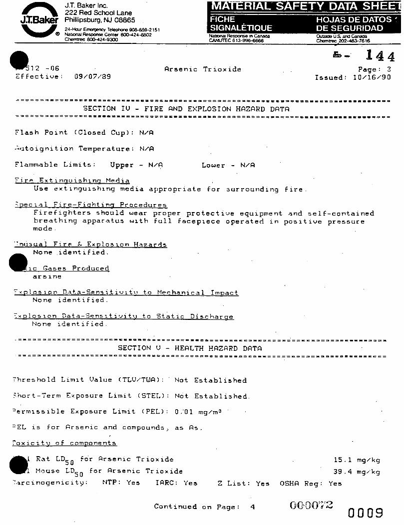
a 7 2 -06 E f f e c t i v e : 09/07/83
A r s e n i c T r i o x i d e P a g e : 3 I s s u e d : 10/16~*90
F l a s h P o i n t (Closed C u p ) : N / A
;:tito i g n i t ; i o n T e m p e r a t u r e : N/A
F lammable L i m i t s : Upper - N / A Lower - N / A
Tirp E x t i n a u i s h i n o MPdia U s e e x t i n g u i s h i n g med ia a p p r o p r i a t e for s u r r o u n d i n g f i r e
' a e c i a l F i r e - F i n h t i n o P r o c e d u r p s F i r e f i g h t e r s s h o u l d w e a r p r o p e r p r o t e c t i - J e e q u i p m e n t a n d s e l f - c o n t a i n e d h r e a t h i n g a p p a r a t u s w i t h f u l l f a c e p i e c e o p e r a t e d i n p o s i t i v e p r e s s u r e mode
. ' n u s u a l F i r e . F, E x p l o s i o n H a z a r d s None i d e n t i f i e d .
i c Gases Produced a r s i n e
- r . ~ u 1 0 5 i o n D a t a - S e n s i t i v i t i l t o k l echan ica1 I r n D a c t None i d e n t i f i e d .
7 x D l o s i o n G a t a - : < ? n s i t i v i t v t o S t a t i c D i s c h a r o e None i d e n t i f i e d .
T h r e s h o l d L i m i t V a l u e !TLV/'TWR): ' Not E s t a b l i s h e d
5 ' n o r t - T e r m E x p o s u r e L i m i t (STET,) : Not E s t a b l i s h e d .
' e r m i s s i b l e Exposure L i m i t ( P E L ) : 0:Ol m g / m 3
'EL i s f o r f i r s e n i c a n d compounds, as Fis.
7 o x i c i t u D € comnonents
1 R a t LDsO f o r Flrsenic T r i o x i d e
Mouse LDsO for R r s e n i c T r i o r i d e
15 .1 mg/kg
3 9 . 4 mgl'kg
' : a r c i n o g e n i c i t y : NTP: Y e s IARC: 'fes 2 L i s t : Y e s OSHQ Reg: Y e s
C o n t i n u e d o n Page : 4
222 R e d School Lane Phillipsburg, NJ 08865 24-Harr Terechge 908-859-2 15 1
ReSDonse Center 800-424-8a02 chenrcrec 800-424-9300
R r a e n i c T r i o x i d e
C a r c i n o a e n i c - i t u T h i s s u b s t a n c e is l i s t e d as a NT.P human c a r c i n o g e n a n d a n I R R C human c a r c i n o g e n ( G r o u p 1).
-. - e ur r) CT :.IC t i w e E i f e c t 3
None i d e n t i f i e d .
1 NHFILQT I Of4 : h e a d a c h e , c o u g h i n g , d i f f i c u l t b r e a t h i n g , c h e s t p a i n s , s e v e r e l u n g i r r i t a t i o n , p u l m o n a r y edema, a n d may be f a t a l
SKI t I CONTRCT : i r r i t a t i o n , p r o l o n g e d c o n t a c t may c a u s e d e r m a t i t i s
. EYE COIJTQCT: i r r i t a t i o n
SKI!4 QBSORPTION: none i d e n t i f i e d
INGESTION: n a u s e a , v o m i t i n g , g a s t r o i n t e s t i n a l i r r i t a t i o n , c o n u u 1 5 i o n s , p a r a l y s i s , b u r n s t o mouth a n d t h r o a t , a n d may be f a t a l
Ci-IFi~NIrJ EFFECTS. damage t o l i w e r , k i d n e y s ~ l u n g s , S l o o d , c e n t r a l n e r v o u s s y s t e m
T a r o e t Oraans l i v e r , k i d n e y s , s k i n , r c s p i r a t o r y s y s t e m , l u n g s , c e n t r a l n e r v o u s s y s t e m , l y m p h a t i c s y s t e m , b l o o d
. : y d i c a l C o n d i t i n n s Ganersllu h u r a u a t e d bv E x u ~ s u r e none i d e n t i f i e d
?rimarv R o u t e s o f E n t r v i n h a l a t i o n , a b s o r p t i o n , e y e c o n t a c t , s k i n c o n t a c t j i n g e 5 t i o n
- -merc[cncxt a n d F i r s t R i d P r o c e d u r e s
INGESTION: C R L L . R PHYS'ICI9N. I f s w a l l o w e d , i f c o n s c i o u s , i m m e d i a t e l y i n d u c e u c ; m i t i n g .
TNHRLFITIOfJ: I f i n h a l e d , remove t o f r e s h a i r . I f n o t b r e a t h i n g , g i v e a r t i f i c i a l r e s p r r a t i o n . I f b r e a t h i n g is d i f f i c u l t , g i v e o x y g e n .
C o n t i n u e d o n P a g e : 5

J.T. Baker Inc. 222 R e d School Lane Phillipsburg, NJ 08865 24-Harr Enrepenc~ Tekchone 908-859-215 1 N a W Resame Center 800-424-8602
R r s e n i c T r i o x i d e
SKIN CONTRCT: I n case of c o n t a c t , i m m e d i a t e l y f l u s h s k i n w i t h p l e n t y o f w a t e r for a t l e a s t 1 5 m i n u t e s whi' le r e m o v i n g c o n t a m i n a t e d c l o t h i n g a n d s h o e s . Wash c l o t h i n g b e f o r e re-use.
EYE CGNTACT: I n c a s e o f elie c o n t a c t , i m m e d i a t e l y f l u s h w i t h p l e n t y of w a t e r for a t l e a s t 15 m i n u t e s . .
SQRa/TrTI.E TIT F;'QZQI?D CRTEGORTES and LTSTS
- c u t e : 'fss C h r o n i c : Yes F l a m m a b i l i t y : No P r e s s u r e : No R e a c t i v i t y : No
Z x t r e m e l y H a z a r d o u s S u b s t a n c e : Y e s C o n t a i n 5 Q r s e n o u s O x i d e 'RQ = 5 , 0 0 0 LZS,
:ERCLa H a z a r d o u s S u b s t a n c e : Yes C o n t a i n s A r a e n o u s T r i o x i d e ( R Q 0 5 0 0 0 LBS) TPQ = 1 0 0 / 1 0 , 0 0 0 LBSI
RQ 313 T o x i c C h e m i c a l s : Y e s C o n t a i n s A r s e n i c G e n e r i c C l a s s : c15 @ aCQ I n v e n t o r y : Y e 5
3 t a t e L i s t s : For p r o d u c t s s o l d i n t h e s t a t e o f C a l i f o r n i a , the s t a t e r e q u i r e s ' hat. we p r o v i d e t o u s e r s arid t h e i r e m p l o y e e s t h e f o l l o w i n g m e s s a g e : W A R N I N G : " X I S PRODUCT I S Q CHEHICRL KNOWN TO THE STRTE OF CFILIFORNIR TO CFlUSE CQNCER.
5 t . a b i l i t y : S t a b l e H a z a r d o u s P o l y m e r i z a t i o n : W i 1 1 n o t o c c u r
' . - , n d i t i o n s t o R v o i d : none d o c u m e n t e d
: n c o m p a t i b l e s : s t r o n g o x i d i z i n g a g e n t s , c h e m i c a l l y a c t i v e m e t a l s , a l u m i n u m , s t r o n g a c i d s , s t r o n g b a s e s
i e c o m p o s i t i o n P r o d u c t s : a r s i n e
;t*eps t o be T a k e n i n t h e E v e n t o f a S D i l l or D i s c h a r g e - Wear s e l f - c o n t a i n e d b r e a t h i n g a p p a r a t u s a n d f u l l p r o t e c t i v e c l o t h i n g . W i t h c l e a n 5 h o w e 1 , c a r e f u l l y p l a c e m a t e r i a l i n t o c l e a n , d r y c o n t a i n e r a n d c o w e r ; remove from a r e a . F l u s h s p i l l a r e a w i t h w a t e r .
C o n t i n u e d o n P a g e : 6

I - ~- - 1 222RedSchoolLane
J X W Phillipsburg, NJ 08865
Ef.f ect ive : 09/07/'89 Flrsenic Trioxide
Issued: 10/16 / '90
DisDosal Procedure Dispose in accordance with all applicable federal, 3tate, and l o c a l environmental regulations.
EPR Hazardous Waste Number : F012 (Rcute Hazardous Waste)
"cnt ilation: Use adequate general or local exhaust ventilation to keep fume or dust lewels as l o w as possible.
F r.espiratory Protection: None required where adequate. ventilation conditions exist. If airborne concentration i s high, a
' high-efficiency particulate respirator is recommende If concentration exceeds' capacity of' respirator , a self-contained breathing apparatus is advised.
ZyeI'Skin Protect ion: Safety goggles , uniform, apron, proper gloves are recommended.
.. .:.kL ~ - D R T R + Storage C o l o r Code: Blue (health)
3 tor aae Reau i r ement s Keep contarner tightly closed. Store in secure poison area.
h ;.:,mastic (D.O.T. 1
'roiyer Shipping Name: arsenic trioxide, 501id Xazard Class: Poison B ?-:!.b't.IFi : 341561 Reportable Quantitli: S O 0 0 LBS.
?egulatory References: 4SCFR 172.101; 173.366; 173.368 Labeis: POISON
-
Continued o n Page: 7

J.T. Baker Inc. 222 R e d School Lane '
Phillipsburg. NJ 08865 24-Ha~rEmergwry T ~ 9 0 8 - 8 5 9 - 2 1 S l NatoMl R e m Cent- 800-424-8802 ChemCreC 800-424-9300
.1 1-/5:2 -06 E-f f ect ive : 09/07~'39
Rrsenic Trioxide . 144 &a C'.
Page: ? I s s u e d : 10/i6/90
. . International ( 1 . t l . O . )
?roper Shipping Name: Arsenic trioxide Eazard Class: 6.1 I.H.O. Page: 6072 :-7N: UN1561 Marine Pollutants: No Packaging Group: XI La'bels : POISOt-J zegulatory References: 49CFR 172.102; Part 176; IMO
.-. .:roper Shipping Name: Arsenic trioxide Yazard Class: 6.1 I T ? ( : UN15G.1 Labels: POISON
Packaging Group: XI
gulatory References: 49CFR 172.101; 173'.6; Part '175; ICRO/IFITR
Customs Harmonization' Number: 28259000000
.*.iiA = blot Applicable or Not Available +:,.'E = t-lot Established
- 3 , n e information in this Material Safety Data Sheet meets the requirements of the United States OCCUPRTIONAL SRFETY AND HERLTH RCT and :.cgulations promulgated thereunder (29 CFR 1910.1200 et. seq. 1 and the ::anadian WORKPLQCE HRZRRDOUS MATERIALS INFORMQTION SYSTEM. This document ::> intended only as a guide to the appropriate precautionary handling of the material by a person trained in, or supervised by a person trained :n, chemical handling. The user is responsible for determining the grecautions and dangers of this chemical for his o r her particular .3pplication. Depending on usage, protect iwe clothing including eye and face guards and respirators must be used to avoid contact with material ~r breathing chemical vapors/fumes. ~xposure to this product may have serious adverse health effects. This ... hemicsl may interact with other substances. Since the potential uses .ire so varied, Baker cannot warn of all of the potential dangers of use I..r interaction with other chemicals o r materials, Baker warrants that the chemical meets the specifications set forth on the label.
'ER DISCLRTWS W J Y OTHER WQRRANTIES EXPRESSED OF? IilPLIED WITH REGARD THE PRODUCT SUPPLIED HEREUNDER, ITS MERCHRNTQBILITY OR ITS ,FITNESS
c
.' f3R R PRRTICULAR PURPOSE. The u s e r should recognize that this product can cause severe injury and even death, especially if improperly handled or the known dangers of use 3re not heeded. REFID QLL TRECAUTIONQRY INFORMRTION, Q5 new documented
Continued on Page: 9 0009
1 222RedSchoolLane JIW Phillipsburg, NJ 08865 24HolEnrergency TeleUmmS38-8542151 NarpMIRes~ameCenter 800-424-8802 chemwc 800-424-9300
;.;7!51.2 -G6 . Y
Zf f e c t i v e : 09/07/'89 A r s e n i c T r i o x i d e Page
I s s u e d : 1 0 / 1 6 i 9 0
g e n e r a l s a f e t y i n f o r m a t i o n becomes a v a i l a b l e , Baker w i l l p e r i o d i c a l l y ~ e u i s e t h i s M a t e r i a l S a f e t y Data S h e e t . If you haue a n y q r i e s t i o n s , ? l e a s e c a l l Customer S e r v i c e (1-800-JTBRKERI for a 5 s i s t a n c e .
COPYRIGHT 1990 J . T . BQKER INC. - - -
TXQDEMRRKS OF J . T . B A K E R IPJC. 1P
p p r o u e d b y Q u a l i t y A s s u r a n c e Department.
-- LQST PQGE --

144 4.,
BP CHEMICALS MATERIAL SAFETY DATA SHE=
/a9 7 BP America (In Ohb): 800-362-8059
CHUAlRECAsstst:80&424-9300 (ouwde Ohb): 800-321-8642
- ,
outside o b - 800-537-9720 Imide Ohio - 800-472-9922
I 24-HOUR EMERGENCY ASSISTANCE I GENERAL ASSISTANCE INFPA FIRE HAZARD SYMBOil
MSOSNumber> 1389 '- - ?-E
MANUFACT1IRER: BP Chemicals ADDRESS: 200 P u b k Square. Cleveland. OH 441142375
TRADE NAME:
AQUA AMMONIA
CAS NUMBER: SYNONYM(S): CHEMICAL FAMILY: MOLECULAR FORMULA: MOLECULAR WEIGHT: PRODUCT CODE:
1336-21-6 AMMONIUM HYDROXIDE SOLUTION AMMONIA NH40H in water 35.05 v 6457 HIERARCHY: 230.050
INGESTION: m y came burpkrg pain of the mouth, throat and aMrawn axxi coug-g and constriction of the m o a t , followed by nausea, v d t i n g and diarrhea.
*&pymhtQ 1980, National Fre Proteaion MA 02269. . This repnnied material is not the complete and official W h n of the NFPA on the referenced subjed. which b represented oniy by tne stantiad in its entirety.
fi ::. 2 ,. -- ;KIN:
ExTxmPzY m X N G AND CQR€C:ZV’E. Contact may cauae reddapFp9, it-, h f 1 e i O n . bllsteriaq and t i s a w drhaqe. C o o t a c t w i t h UqU6affed =tar- znay cause frostbite.
ZY E: -Y IRSUTUpx; AND CQRRDSIV2. and temporary c o r n e a l o p a d t y .
D i r e c t contact may cause k i t a t i o n , corner1 edema Severe exposure may prodace pia-ent damage.
INHALATION: S W c 3 I I L I TOXXC, Hay cause r e s p i r a t o r y tract k r f t a a o n , coug-g, difficulty in breathbg and w a a r y edema. w U c h p r e v e n u breathirrg.
Severe ezpoaure m y apse awe- o f moueh t h r o a t to +he point Way ala0 -ge the heart, Uvec and kiQey.
SPECIAL TOXlC EFFECTS: Ercess b - is detoxified h the Uver by COnmtsion to urea. Those w i t h a &tory of reduced liver f u n c t i o n should avoid ergosure to -nb.
INGESTION: ~k mD- VOHITPfG. I f V i C t b n is C O O ~ C ~ O U ~ , give 1-3 glasses of water or to
a l u t e ato-ch c o n t e n t s . . 72ep a f f e c t e d person warxn and a t rest. a r t e n t i o n .
Get -&ate medical
S K I ~ J CONTACT: Wash area of c o n t a c t thoroughly w i t h soap and w a t e r . Remove contanrrnated c l o t h i n g a d a t e l y . Launder c l o t h k g before reuse. G e t m e d i c a l a t t e n t i o n i f i r r i t a t i o n p r s ~ a t a . Contact w i t h liquefied gas aay c a u s e f r o s t b i t e . G e t -&ate =dical a t t e n t L o n .
EYE CONTACT: a Fluah bnxiedL a t e l y with large = u t a of water for a t l e a s t 15 rrrinutes. Eyelids should held avay frorn.the eyeball t o --e thorough rinsing. G e t -&ate medical a t t e n t i 0
INHALATION: w v e a f f e c t e d person f=an source o f ezpoaute. If not breatlcing, ensure open airway and k t i t u t e ~ a r d i ~ p ~ h ~ ~ r y r e s u x i t a t i o n (CPR). If breathinr, i s difficult, arkainiater oxygen u a v a i l a b l e . Keep a f f e c t e d person =inn and a t r e s . G e t -ate d c a l a t t e n t a o n .
EYE PROTECTION: Wear u c a l s a f e t y goggles arrd face sUeld. available where e y e c o n t a c t can occur. substance.
Have eye was- f a c i l i t i e s readily Do not near contact l-ses when working w i t h this
NO = N O Oata NA P Not Applicable
1389 lPage2of 6

:KIN PROTECTION: uear l q e r p i o u s gloves d a d p r o t e c t i v e clothing t o prevent skin c o n t a c t . Suggested
r o t e c t i v e m t e r i a h are: rovide safety showers a t any l o c a t i o n where skin contacf can o c c u r .
Butyl rubber, Neoprene, Nltri,le rubber and P o l p i n y 1 cblorihe.
RESPIRATORY PROTECTION: Use NIOSH or HSHA approved equipment when airbarne exposure l-ts are exceeded. NIOSH/KSRA approved breathing equipment zmy be required for. non-routine emergency use.
BOILING POINT: NO SPECIFIC GRAVITY: 0.89
% VOLATILE: 100.0 VAPOR PRESSURE: 420.00 - 475.00 MM HG @ 15.5 C EVAPORATION RATE (WATER=I): S I M I U R VAPOR DENSrrY (AIRz l ) : VISCOSITY: NO 3; SOLUBILITY IN VJATES: ?OUR P0lf:T. :JA
2H: ~ P P E k R ~ t ~ C € ; O D O R : C = ~ ~ ~ ~ LIQULD WIT:? Z:XO::G ;L!O:IU CDOR.
MELTING POINT : -78.0 C (-108 F)
c 1 .O
: 1: 0
-LASH POINT: NA - AUT 0 I G N I TI 0 N TE ?A P E il ATU R E : FlJ?.l?.lABlLTTY LIMITS IN AIR ( X BY VOL.) LOWER: 16.0 UPPER: 27.0
e31 -00 C (1204 F) (AMMONIA)
BASIC FIREFIGHTING FROCEDURES: U 3 e a W a t e r apray Z o cool fire--sed containera 'and atnxzturea, disperae vapors and to p r o t e c t Frsonnel. f i r e i f qaa nource can=== be s h u t o f f .
S h u t off Source o f flow i f p o s a i b l e . 30 n o t a t t c q t EO e r r h g u i a h
UNUSUAL FIRE AND EXPLOSION HAZARDS:
-sed f i r e f i g h t e r 3 should wear s e l f - c o n t a i n e d breathing apparatus with F i r e may produce pofsonoua o r i r r i t a t k g gas, ftrmes or vapor. heat of f i r e . full face mask.
b n t a h e r a -y explode i3
STABlLrrYll t4COUPATI BILTY: Stable under no-1 COnc!itiOnS of use. Subject t o erothennic reaction with acids. I n c o q a t i b l e w i t h a c i d s . hypochlorites (bleach), and soditrzn hydcoxide. Avoid contact with iron. galvanized :urfaces, copper, brass, bronze, alurPinul a l l o y s , mercury, gold and s i l v e r .
H AZ ARDOU S REACT10 NSID ECOMPOSlTl ON PRODUCTS: Decoqoses t o w a i a c a s , and above 450 C ( 8 4 2 F ) , to h y d t q e n and ni t rogen gaaes.
a NO = NO Data NA = Not Aoplicable
1389 /Page 3 01 6
SPILL OR RELEASE TO THE ENVIRONMENT: If your facility or optintion has an "Oil or Hazardous Sub- COntiPgenCy Plan', a c t i v a t e its procadures.
-- fake -tat steps t o stop and contakr the s p i l l . Caufion should be ererebed tegardiPg peraonnel s a f e t y and exposure t o tbe sp- zaaterial.
-- ?or technical advise and a s s f s t a ~ c e r d a t e d to chemicah, contact CHEHTECEC (800/424-9300) d 1-L ffre depa-t.
-- Notify the National Raspoase Center. if required.
Emergency Actlon: Xeep unnecessary people away. protection Info-tion section.
I s o l a t e hazard area and deny e n t r y . (Also see Personal
Splll or Leak Procedure: Do not touch s p i l l e d w t e r i a l . Stop leak if you cas do it without r i s k . Taka up w i t h a d or other noncombustible absorbent rruterial o r o t h e r sorbent known t o be c o q a t i b l e , then f l u s h area with water. Small Dry S p i l l s : Shovel i n t o aty containers and cover: a v e containers: then f luah area v i t h water. Large S p i l l s : Dike f a r ahead Of a p i i l f o r l a t e r disposal.
S m ; r l l S p m :
~~ ~ ~~~~~~ ~
Notification: The reportable quantity f o r t h i s material i s 1,000 pound(a)
h y s p i l l or other release, o r subatantial threat o f release, of t h i a r a t e r i a l t o the a i r , water, or land (unless entirely contained in the workplace) equal to or in excess of the
' a t e l y t o t h e National Response Center (800 4 2 4 - 8 8 0 2 ) as required by U.S. Federal Law. Failure t o report may r e s u l t s u b s t a n t i reportable quantity nzust be reported hneda
c i v i l and cr-1 p e n a l t i e s . a WASTE DISPOSAL:
TUS substance, when discarded o r diaposed o f , ia n o t specifically l i s t e d a s a hazardous vaste irr Federal r q u l a t i o n a ; however it could be hazardoru if it ia considered t o x i c , corrosive, ignitable, or r e a c t i v e according t o Federal d e f m t i o - ( 4 0 CE7L 2611. Additionally, ft could be designated a s hazardous according to s t a t e r e g u l a t i o n s . This substance could a l s o becamcj a hazardous vaste i f it b & with o r comes in c o n t a c t w i t h a hazardow w a s t e , If such contact or m(rinrr may have OCCPrred, check 4 0 CZ?R 261 to deterniae whether it is a hazardous waste. If it i s a hazardous waste, regulations . a t 4 0 rn 262, 263, . and 2 6 4 apply.
Ihe transportation. storage, treatment, a d disposal of this waste material a t be conducted in coaapliance with a l l applicable Federal, s t a t e , and l o c a l r e g u l a t i o n s .
SARA TITLE 111 INFORMATION:
Listed below are tbe hazard categories f o r the Superfund -ts d mauthorfzatfon A c t (ShRh) Section 311/312 ( 4 0 (TR 370) : lmmedlate Hazard: X Debyed Hazard: X FIre Hazard: 2 Pressure Hazard: Reactlvlty Hazard: - - - The product Contains the following t o x i c chem.ical(s) subject to the reporting requiterrenth of t h e Superfund Amzn-ts and Reauthorization Act (S-1 Section 313 ( 4 0 CFR 3 7 2 ) :
NO = No Data NA = Not Applicable
1389 P a g e 4 o f 6

Component: CAS Number: Marlmum Ye Ammonia 7664-41-7 30.0
,DDITONAL ENVlRONMENTAL REGULATORY INFORMATION: There may be specific r e g u h t i o n s a t the local, regional or s t a t e l e v e l that pertain t o this znatptial.
iANDLINGISTORAGE: S t o r e in tightly closed confahers in COOL dry, isolated, well-venfilated area a w a y from heat, sources of ignit ion and incoznptihles.
q t y containers may contain t o r i c , f - l e / c e t i b l e o r arplosivea reaidue or vapors. Do n o t mt, grind, drill, w e l d or reane containers unless adeqrtate precaution8 &re a g a i n s t these hazards.
D.O.T. HAZARD C U S S (49 CFR 172101): D.O.T. PROPER SHIPPING NAME (49 CFR 172101): D.O.T. LABELS REQUIRED (49 CFR 172101):
D.O.T. PLACARDS REOUIRED: CORROSIVE
CORROSIVE AMMONIA HYDROXIDE (AOUA AMMONIA) CORROSIVE
BILL OF LADING DESCRIPTION: mm mROXII)E, CONTAINS 12-44% AMNONIA, CORRDSXVE
HATERI;U. NA-2672 “RQ” UN/NA CODE: NA 2672
~ e m a l n r n g components not HA Trace XA .
d e t e d e d hazardous and/or hazardous conxponenrs present at l e s s - A n 1.0% (0.1% f o r carciawens1 .
1389 iPageSof6

1389 Page 6of 6
J..
/ I / 86 - .- ric .
a -. 7.' Occupational Health Guideline for \
Soluble Barium Compounds (as Barium)
INTRODUCTION PERMISSIBLE EXPOSURE UMlT (PEL)
This guideline is intended as a source of information for employees, employers. physicians. industnal hygienists. and other occupational health professionals who may havc a need for such information. It does not attempt to present all data; rather, it presents pertinent information and data in summary form.
APPLICABILITY
Tbc current OSHA standard for soluble barium com- pounds is 0.5 milligram of soluble barium compounds p a cubic meter of air (muma) averagcd over an eight- hour work shift. R CGZW T L V i s 0 4 '%a
HEALTH HAZARD INF Routes of exposare
Soluble barium compounds can
skin- They can also affect the M Y 8 hey are SUA-
lowed- * effect so form.^ 1. Shomenn & p u r r : Soluble barium compounds my c a w local irritation of the eye , nose. throat, broncM tubes. and skin. Soiuble barium compounds may alio
L _ . - I __
g e n e i guidelines contined in this document arc inhaled or if they come in contact &bith the eyes 31
apply to all soluble barium compounds. Physical and chemical properties of several specific compounds are ' . * -
- . provided for illustrative purposes.
SUBSTANCE I DENTI FlCATlON
Barium nitrate . . Formula: Ba(N0a)t
Synonyms:None Appearance and odor: Odorless white solid.
Barium oxide
Formula: BaO Synonyms: None Appearance and odor: Odorless white solid.
Barium carbonate
Formula: BaCOa Synonyms: None Appearance and odor: Odorless white solid.
Barium chloride
Formula: BaCh Synonyms: None Appearance and odor: Odorless white solid.
caw severe stomach pains, slow pubc rate, irreguir bean beat. ringing of the can. diuincss. convulsiozs. and muscle spasms. Death may occur. 2 Long-term f i p n r r : None known 3. Reporting Signs and Symptoms A physician should 5e contacted if anyone develops any signs or symptoz and suspects that they are caused by exposure to solutie barium compounds.
Recommended medical surreillance The following medical procedures should be made available to each employee who is exposed to solu:!~ banum compounds at potentially hazardous levels: 1. Initial Medical Exammatwn:
-A complete history and physical examination: Tie purpose is to detect preexisting conditions that mi@ place the exposed employee at increased risk. and to establish a baseline for future hcalth monitoring. Exam- Muon of the heart. lungs and nervous system should 5c stressed. The skin should be examined for evidence Jf chronic disorders.
-14" x 17" chest roentgenogram: Soluble b a n m compounds caw human lung damage. Surveillance of the lungs is indicated.
These recommendations reflect good mdustnal hygiene and medical surveillance pracbces and their implementation w:i assist in achteving an effectwe occupational health program. However. they may not be sufficient to ameve compliane
with all rewirements of OSHA regulations.
U.S. OEPARTMENT OF HEALTH A N 0 HUMAN SERVICES PUOIIC Health Setwce Centers for hsease Control NamnaI lnstltule for OCCuPaWMl Safety and Health
US. DEPARTMENT OF LABOR Ocarpatrnal Safety an6 Health Admanuam

. . . . . -WCgnd FEV (1 sec): Soluble barium compounds are respiratory imtanu Persons with impaired pulmon- ary function may be .at increased risk from exposure. Periodic surveillance is indicated.
-Electr~~rdiogram:-Barium compounds may cause cardiac arrhythmias and may have a direct effect on the cardiac mu.%le. Periodic surveillance of the heart is indicated. 2. reriidic .Ifdcal €rumination: The aforementioned medical examinations should be repeated on an annual basis. except that an x-ray is necessary only when indicated by the results of pulmonary function testing, or by signs and symptoms of respiratory disease.
Summary of toxicology Soluble harium salts cause severe gastroenteritis and systemic effects by ingestion. Intravenous injection of barium compunds.in animals causes a strong, pro- longed stimulation of muscle resulting in hyperperistal- sis, bladder contraction. vasoconitriction. and irregular contraction of the heart followed by arrest in systole. Animals also exhibit stimulation of the centd nervous system followed by paralysis. Ingestion of barium car- bonate by humans causa gastroenteritis. muscular pa- ralysis, s l o u pulse rate. extrasystoles. and hypokalemia Heavy industrial exposure to dusts of barium sulfate or barium oxides may produce a benign pneumoconiosis. termed baritosis. It results in no impairment of ventila- tory function. although signs of mild bronchial irritation may occur. Characteristic x-ray changes are those of small. dcnse. circumscribed nodules evenly distributed throughout the lung fields, rcflecting the radiospacity of the barium dust. Bronchial irritation has been repon- ed from the inhahtion of barium carbonate dust. Barium hydroxide and barium oxide are strongly alkaline in aqucous solution. causing severe bums of the eye and irritation of the skin.
CHEMICAL AND PHYSICAL PROPERTIES
Physical dita-8arium nitrate 1. ,Molecular weight: 261.4 - 2. Boiling point (760 mm Hg): Greater than 592 C
3. Specific gravity (water = I): 3.24 4. Vapor density (air = I at boiling point of barium
5. Melting point: 592 C (1098 F) 6. Vapor pressure a- 20 C (68 F): Essentially zero 7. Solubility in water. g/IW g water at 20 C (68 F):
8. Evaporation rate (butyl acetate = 1): Not applica-
(greater than 1098 F) (decomposes)
nitrate): Not applicable
9.2
ble Physical dab--Barium oxide 1. Molecular weight: 153.3 2. Boiling point (760 mm Hg): 2000 C (3632 F) 3. Specific gravity (water = 1): 5.72 4. Vapor density (air = 1 at boiling point of barium
5. Melting point: 1921 C (3490 F) . oxide): Not applicable
2 Soluble Barium Compounds (as Barium)
6. Vapor pressure at 20 C (68 F): Essuulsliy zero 7. Solubility in water. g/ 100 g water at 20 C (68 0. 8. Evaporation rate (butyl acetate = I): Not applica-
.*
k S C U
ble Physical data-BuiPm carbonate 1. Molecuiar weight: 197.3 2. Boiling point (760 mm Hg): 1300 C (2372
(decomposes) 3. Specif;,- ravlty (water = 1): 4.25 4. Vapo: n.c:c*. (air = I at boiling point of barium
5. Melting point: Decomposes at 1300 C (2372 F) 6. Vapor pressure at 20 C (68 F): Escntially zero 7. Solubility in water. g/lOO g watcr at 20 C (68 F):
0.0022 8. Evaporation rate (butyl acetate = i):-Not_rpplica-
ble Physical data-Bariom chloride 1. Molecular weight: 208.3 2. Boiling point (760 mm Hg): 1360 C (2840 F)
4. Vapor density (air = 1 at boiling point of barium
3. Melting point: 963 C (I 765 F) 6. Vapor pressure at 20 C (08 F): Essentially zero 7. Solubility in water, g/lOO g water at 20 C (68 F):
S. Evaporation rate (butyl acetate = 1): Not applica-
-
~ m- carbonate): - t aijplicable
1 - ..
fa..-- *
2 h??T-
- L. . 3. Specific gravity (water = I): 3.86 ., -. . - chloride): Not applicable
36
ble ..Pt. * Reactivity 1. Conditions contributing to instability: For bari
nitrate. elevated temperatures may cause melting an decomposition: for the other compounds. none hazard- OU.
2. Incompatibilities: Contact of barium oxide with water, carbon dioxide, or hydrogen sulfide may cause fires and explosions. Contact of banum carbonate with acids causes formation of carbon dioxide gas that may cause suffocation in enclosed spaces. Contact of h u m nitrate with organic matter and combusublc mater& may cause fires and explosions.
3. Hazardous decomposition products: Toxic gascs and vapors (such as oxides of nitrogen and carbon monoxide) may be released in a fire involving barium nitrate
FlammPbility 4. Special precautions: None
1. Flash point: Not applicable 2. Autoignition temperature: For barium nitrate, data
not available; for the the other compounds, ~ o t applica- ble.
3. Flammable limits in air. 9% by volume: Not appli- cable
4. Extinguishant: Large amounts of water should be used on adjacent fires.
Warningproperties According to Grant, banum chloride c a l l c r n s i d e r - able iritis. which subsides in a few days" whea "tested
sllecrakr 1978
- . .->. . -- .-.. 9- . . . . . . . . . . . . . . . . . .... . . . . ... ..... ..... . . . . . . . . . _,i ____ . . . . . . . . . . . . .
._ . _- .--~

in neutral 0.08 to 0.1 31 solution on rabbit eyes by injection into the coma o r by dropping for 10 minutes on the eye after the corneal epithelium was removed to facilitate penetration." Grant states that "both the'oxide and hydroxide are capable of causing severe alkali bums t
, of the eye. similar t o those produced by calciuni hy- droxide"
MONITORING AND MEASUREMENT PROCEDURES
Cenerrl Measurements to determine employee exposure itre best taken 50 that the average eight-hour exposure is based on a single eight-hour sample or on two four-hour samples. Several short-time interval samples (up to 30 minutes) may also be used to determine the average exposure level. Air samples should be t a k i in the ernployee*s breathing zone (air that would most nearly represent that inhaled by the employed.
Method SamplinS and analyses may be performed by collection on a cellulose membrane filter followed by leaching in
hot water. solution of sample in acid. and analysis in an atomic absorption spectrophotomekr. An analytical method for soluble barium compounds is in the N K N f .Uanuol oj'..lnulytrcol .Methods 2nd Ed.. Vol. 3. 1977. available from the Govcriimcnt Printins Ofice. Wash- ington. D.C. 20402 (GPO NO. 017-033-00161-4). 0- RESPIRATORS
, Good industrial hygiene practices recommend that .engineering conirols be 3sed to reduce environmental conccntrations to the permissible exposure level. How- ever, there are some exceptions where respirators may be used to control exposure. Respirators may bc used when engineering and work practice controls are not technically feasible. when such controls are in the process of being installed. or when they fail and need to be supplemented. Respirators may also be used for operations which require entry into t a n k or closed vessels. and in emergency situations. If the use of respirators is necessary. the only respirators permitted are those that have been approved by the Mine Safety and Health Administration (formerly Mining Enforce- ment and Safety Administration) or by the National Institute for Occupational Safety and Health.
In addition to respirator selection. 3 complete respira- tory protection program should be instituted which includes regular training, maintenance. inspection. Ckking, and evaiuation.
.
PERSONAL PROTECTIVE EQUIPMENT Employees should be provided with and required to
wiqervious chh~ng, .glovs face shields (e ightkch minimum). and orher appropriate protective clothing
nccswy to prevent repcated or I r = prolonged s L a s t wirh banum carbonate h n u m chloride, barium rutrate.' or liquids conmnmg these compounds.
Employees should k provided with and required to w impcrvtout clothing, gloves, facc shields (eight-inch minimum), and other appropriate protective dothing ncccSSary to prevent skin contact with banurn oxide or liquids containing barium oxide, where skin contact may occur.
If employees' clothing has had any possibility of being contaminated with barium carbonate. barium chloride. barium nitrate. barium oxide. or liquids con- taining these compounds employees should change into uncontaminated clothing k f o n laving the work prem- ises. -iG- .$-C
Clothing contaminated With barium carbonate. barium chloride, barium nitrate, or buium oxide should
p l a ~ e d in dosed containers for stom& untit it can be discarded or until provlsion is made fm the removal of contaminant from the clothing. If the dothing 2 to be laundered or otherwise clcancd to remove the contami- nant. the perron performing the o&i&Gshodd be informed of contaminant's hazardous propcnie~
Where exposure of an employee's body to h r i u m oxide or liquids containing barium o-de may occur. facilities for quick drenching of the b d y should be provided within the immediate work --for emergen- cy ux.
Non-impervious clothing which becoma contami- nated with barium carbonate. barium chloride. barium nitrate. o r barium oxide should k removed promptly and not rewom until the contaminant is removed from the clothing.
Employees should be provided with and required to use dust- and splash-proof wfcty goggles where there is any possibility of banum oxide or liquids containing barium oxide contacting the eyes.
Employees should be provided with and required to use dust- and splash-proof safety goggles where barium carbonate. banum chlonde. banum nitrate. or liquids containing these compounds may contact the e y a .
Where there IS any possibility that employes' eyes may be exposed to barium oxide or liquids containing barium oxide. an eye-wash fountain should be provided within the immediate work area for emergency use.
SANITATION
Workers subject to skin contact with barium oxide or liquids containing barium oxide should wash any areas of the body which may have contacted barium oxide at the end of each work day.
Skin that becomes mnmminated wirh barium u~hn- ate. barium chloride. or barium nitrate should be promptly washed or showered to remove any contami- nant. In the case of barium carbonate. employees should use soap or mild detergent and water .for washing purposes.
@ Y’*kkin thit &comes contaminated with banum oxide 3houId k promptly washed or showered to remove any b m u m oxide from the skin after ail obvious amounts of bmum oxide have been removed by other means (e.& by t.se of oil or Vaseline). Employees who are being burned hv barium oxide should immediately utilize (IUIL.. d r rxk ing facilities without first removing barium oride by other means.
Fating and smoking should not be permitted in areas where solid barium carbonate, barium ciilonde. banum nitrate. or barium oxide, or liquids containing these compounds are handled. processed. or stored.
Employees who handle barium carbonate. barium chlonde. barium nitrate. barium oxide, or liquids con- taining these compounds should wash their hands thor- oughty before eating, smoking. or using toilet facilities. In the crse of barium carbonate. employees should use w p o r mild detergent and water for washing purposes.
COMMON OPERATIONS AND CONTROLS
Thc following list includes some common operations in sh i ch exposure to soluble barium compounds may txcur and control methods which may be effective in
Operation Manufacture and distribution of soluble barium compounds
U s e in manufacture of pressed and blown glasssware and flint and crown optical glass: manufacture of ceramic products; use in electronics industry in manufacture of magnets. vacuum tubes. cathodes. x-ray fluorescent screens, lV picture tubes, and dry cell depolanters
Use in manufacture of photographic papers. dyes, and chemicals
Use as pesticides, rodenticides, and dmnfectants: use VI manufacture of explosives. matches, and pyrotechnics as igntter compositions
a n d fireworks
Controls
Process enclosure: local exhaust ventilation
Process enclosure: local exhaust ventilation
Process enclosure: local exhaust ventilation’
Process enclosure: locat exhaust ventilation
Use as an sdditive in manutachr. 3 of grease, and manufacture of lubricating oils; use in refining of vegetable and animal oils Use in ws-5ardening of steej - .tallurgy; in weldinc mum: in electro~ 4: and :n aluminum and sodium refining
Use in water treatment and boiler compounds for softening water, use ascata lys ts .~ca l reagents, and purifymg agents
Use for treatment of - textiles. leather, and
rubber, use in manufacture of paper and cellulose as a bleaching agent: use in manufacture of pigments. colors. and lakes
Use as a depilatory in processing of hides: as a fire-proof and extinguishing agent: in embalming; in sugar refining; in gas and solvent drytng; in marble substitutes: in valve manufacture: and as a smoke suppressant in diesel fuels U s e in manufacture of pigments, paints. enamels. and printing inks
Process endosure: localexhaustventilation
.. , . . .. ...i .. . ~
.,:. . .. : ... . . ~ ..... :-. - . ?
. . . . .. . ... . . . - -. - . . Process.encbswe; local exhaustventilation
. _. .. . - . , . ~,. ,‘i ’ ,
; .a: . -,,-:. . - , :.,! . -7 , : : ‘.
. ’.. : . .. . :.. . .. . ,
Process endosue; local exhaust ventilation
Process endosue; local exhaust venthtion
EMERGENCY FIRST AID PROCEDURES
In the event of an emergency, institute first ad proce- dures and send for first aid or ma!ical ~cc~tancc.
Eye Exposore If solutions of b u m compounds get into tbe eyes, wash eyes immediately with large amounts of water, lifting the lower and upper lid4 occasionally. Gct medi-
x a l att&nirmnediatcly..Conract Ltoacs rhaoldaot k *worn when working with these chemicals.
4 Soluble Sarlum Compounds. (as Barlum) rn 1978

RESPIRATORY PROTECTION FOR SOLUBLE BARIUM COMPOUNDS (AS BAWUM) L -- - . i44
Condition Minimum Respiratory Protection. Required Above 0.5 mg/ma 'x
'd Particulate Concentration
2.5 rng/rnJ or less Any dust and mist respirator, except single-use.'
5 mg/mJ or less Any dust and mist respirator. except single-use or quarter-mask respirator.
Any fume respirator or high efficiency particulate filter respirator.
Any supplied-air respirator.
Any self-contained breathing apparatus.
25 mg/m3 or less A high efficiency particulate filter respirator with a full facepiece.
Any supplied-air respirator with a full facepiece. helmet, or hood.
Any self-contained breathing apparatus with a full facepiece.
250 mg/rn:' or less A Type C supplied-air respirator operated in pressuredemand or other positive pressure mode or with a full facepiece. helmet, or hood operated in continuous- flow mode.
A powered air-purifying respirator wdh a high efficiency particulate filter.
Self-contained breathing apparatus with a full facepiece operated in pressure- demand or other positive pressure mode.
A combination respirator which includes a Type C supplied-air respirator with a full facepiece operated in pressure-demand or other positive pressure or continu- ous-flow mode and an aux4ary self-contained breathing apparatus operated in pressure-demand or other positive pressure mode.
--- - .
W Greater than 250 mg/mJ or entry and escape from unknown concentrations a Fire Fighting Self-contained breathing apparatus with a full facepiece operated in pressure-
demand or other positive pressure mode.
Escaoe
~ _ _ ~~
A high efficiency particulate filter respirator.
Any escape self-contained breathing apparatus.
'Only NIOSH-approved or MSHA-approved equipment should be used.
"If eye irritation occurs, full-facepiece respiratory protective equipment should be used.

CHEM REPIlRT 05/23/1986
CHEM 'ID CHEM NAME x .x. * X. G034-86-0 URANIUM COHPOIJNDS
1 4 4
ENTRY I N F O R MATT ON 05/23/1986
DnE CHEHTCAL HAZARDS EMFRGENCY HANAGEHENT SYSTEM 0 5/23/ 1 986
HFRI-TH AND S A F F T Y TNFORMATTQN AUTHOR JTY
DI SPnSAL
RECOVERY FOR RFPRnCFSSTNG URANTUM TS TI-IF P R F F F R R F T ) MFTHOD FOR HAND1 ... JNG WASTE 11RANTIJM CflMPnUNDS. SHTP T f l L I S C F N C E D RECOVFRY F A C T L I T Y , UNRECOVFRED MATER TAI SI-IOIJI D RE HANDI-ED AND PACKAGED AS RADJQACTTUF WASTE S H I P P E D TO A N APPROVFD SITE HY AN APRROUFD D I S P h S A l ... FIRn' .
D E C Q H P Q S I T I O N PRODIICTS
T O X I C CASES AND VAPORS (SUCH A S HYDRf lGFN FI-.lIORTDF.. NITROGEN OXIDFS, AND CARBON MONflXTnE:) M A Y F.E RELEASED WHEN I l R A N T l J M COMPOUNDS DECOflPOSE. SEE S P E C I F I C COMPOI.IND.
ENVIRONMENTAL FFFECTS
NO C R I T E R T A S E T . ElJT FPA SIIGCFST A P F R M I S S I P L E CONCENTRATTON I N WATFR OF 3 I JG/ I . RASED ON HEAI-TH E F F E C T S .
EMERGENCY PROCEDLIRFS
PFRSONS NOT LJEARING PRoTFCTTUF EQIJTPMFNT AND CI..OTHJNI: l iHnlJLD EF: RESTR TCTED FROM AREAS O F SPTLLS I.JNTTL CL.EANIJP H A S BEFN COMPLETED. IF URRNIUM C0HPOI.INDS ARE SPIL.LED . 1 . UFNTTI..ATF. A'REA O F SPTI. . I - , . 2. c r ) ~ . ~ ... ECT S P T L L E D MATFRXAI.. IN THE I l f l S T ~ X N V E N ' I E N T AND S A F E MANNER ArjD DEPOSIT T N S F A L E D CONTATNFRS FOR RFCL-AMATTON I .IOUJ.D CnNTAJNZNG tJRANT.UM OR TNSQI..LJPLE C:DMPOI.JNDS SHOULD )sF ABSflRPFD I N UFRMICl .J l . ITE. nRY S A N D , EARTH ClR A SIHTl...AR f lATERTAl - . SPTI..L AREAS MAY FF. DECONTAHINATED IJSZNT, A SOL~JTIIIN WITH A CHELATING x m - r SUCH AS EDTA.
F I R S T AID
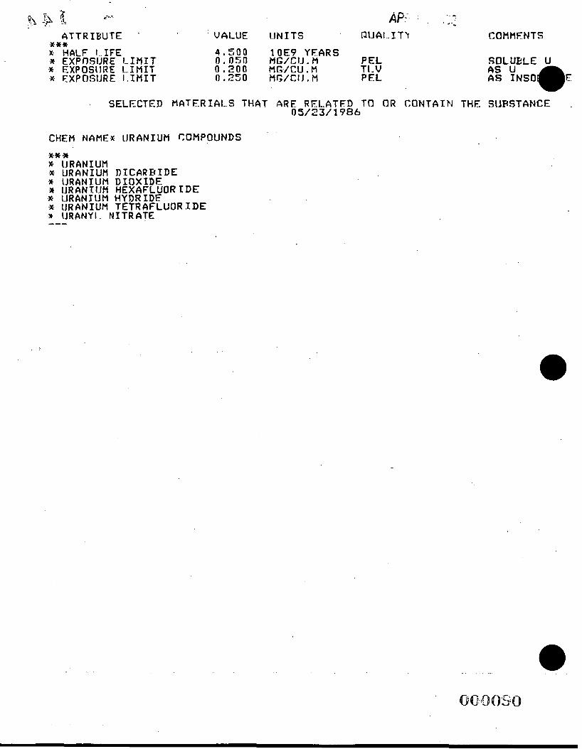
A T T R I B U T E ’ E** x. HALF I..IFE .]E E X P n S U R E LIMIT Q EXPOSiIRE I...IMIT .X. FXPClSlJRE I.IMIT
AF‘ ’ .
. VALUE UNITS ’ OI.IAl..STY COHtlFNTS
4 , 5 0 0 lOE9 Y E A R S 0 , 0 5 0 MG/CI.J. Pl PEL 0 . 2 0 0 flc,./CU.M TI-V 0 . 2 5 0 MG/CIJ.M PEL
SOLUELE u AS u As msoQ E
. S E L E C T E D M A T E R I A L S THAT A R E R E L A T F I ) TO OR CONTAIN THE SIJESTANCE . 0 5 / 2 3 / 1986
CHEM NAMEX 1JRANIUfI COMPOUNDS
E% -x X. IJRANIUM Q U R A N I U H E IJRANIUM Q I.JRAN1:I.JH
% IJRANYI. N I T R A T E
.X. (.IRAN JIJM .X I J R A N I U M ---
D Z C AR B T D E D I ~ X I D E HEXAFLUOR ID€ HYDRIDE TETRAFLUORIDE

ATTACHMENT F WORK AREA MAP
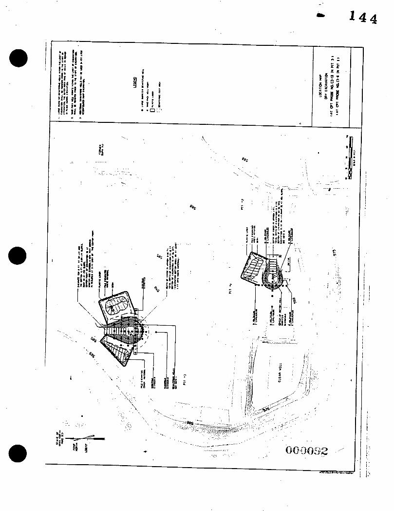
i, 1 4 4
.......... ...
. . . . .. . .
. . . . . . . . . ...... ..:.. ............ - . . . .
. %,
i
. . eer . . . . .... . . . . . . . ..... :..
._ .. . : ... . . . . . . . . . . . . . ... . ... .... .. . . . ,'I ..-
. . ..,:'.._ . _ . .
. . I.. . ~ ~ ~ ~ . *. . .
: : e ' ...
....... .... ....# ......... ......
t CI
.... . . . . .': . .::. :.,
. I .. I '.I 1 I . . . . . . :< . . . . .
! '! I
I
! i
i .
i .- I .
L '
0 .
I .
. ATTACHMENT G OSHA AND DOE RIGHTS POSTER
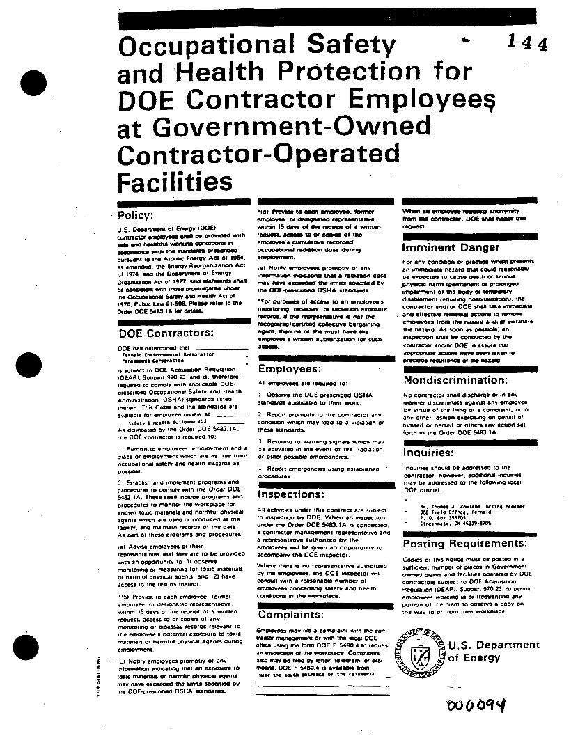
I 4 4 c Occupatio-nal Safety and .Health Protection for DOE Contractor Employee9 at Government-Owned Contractor-Operated Fa c i I it ies
' PolicV:
Imminent Danger
Employees: All cmgco*sr, 81. required to:
: 0- tne OOE.orescrmed OSHA staIy)M. a ~ o u o ~ e to insir worm.
2 Rumn ~romoitv to tne coniractor anv comuon *mm m v maa to a vmutum or in- ~IJWWOS.
3 Raoono to warninq s~gnais wnBcn mav De acwairm in tne went 01 tire. raomtion. or orner - smerqsncm.
4 A e m t emsrganca using estamisneo - OIocCau8rn.
Inspections: All acvntr, unaer inn contract are suoect IO wuaectmn ev DOE. When an unwction unom me Or- ODE sag). 1A u conoucieo. a contractoc mrmgameo1 reoresentatwe ano a reoresentam iucn~mea ov tne emmovea mU lm given an oomnunitv io acQYrOInv cne DOE inroector.
Where inere 1s no reDresenta1ivc autnorirro DV ma F. rne DOE insoector WN comadt win a reasamme numom or emomowes concmung s a e w ana ncattn conOKuu m the r*onouCe.
Nondiscrimination: NO contractor snail o i s ~ ~ r g o or m anv manner discnrnnute -mat 8nv .mol~m bv nnue ot me titinq of a comomrn~. or in anv otncr lasnlon exerauu) on mMi1 01 nirnulf or nersetf or o t m anv 8ctl0n set fonn in tnc Oraer OOE So83.lA.
- inquiries: inouires snould oe aaora- IO tne contractor: nowem. aWIIDNt inauues rnav oe aooresm to tnc toll^^^ ux81 DOE OttIClaI.
~
Postin g R e q u i r ern e n t s : C o o m ot 1hiS notice must ne oos~w a a sutflclent numoer ot DUCES in Govcrnmmt. o m oianrs ana t a d i t r , oOm81cO DV OOE contractors suoiect to DOE Acauwtmn Asgurupn tOEARI. SuooUr 970 23. to oermir emoylvm worcm9 rn or trsouenmq anv ponion 01 me oiant to 0- a CODV on :ne wav 10 or from rnm u+mrLOUCe. Complaints:
ATTACHMENT H ACKNOWLEDGEMENT FORM
.. . .

' ACKNOWLEDGEMENT LOG ** 144 PROJECT SPECIFIC HEALTH AND SAFETY PLAN
RU1 DEWATERING EXCAVATION EVALUATION PROGRAM (DEEP) (DRY EXCAVATION) REV 3
The undersigned individuals have been oriented on the requirements of the attached Project Specific Health and Safely Plan and - understand the provisions of the plan and agree 10 abide by each.
Name . .
Signature m e Badpe No.
H- 1

ATTACHMENT B
PROJECT SAFETY ANALYSIS REQUIREMENTS
0 CRUl IRAMPOFS.PSPI9I13195
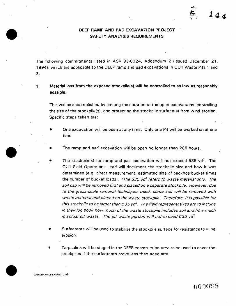
DEEP RAMP AND PAD EXCAVATION PROJECT SAFETY ANALYSIS REQUIREMENTS
The following commitments listed in ASR 93-0024, Addendum 2 (Issued December 21, 1994). which are applicable t o the DEEP ramp and pad excavat ions in OU1 Waste Pits 1 and 3.
1. Material loss from the exposed stockpile(s1 will be controlled to as low as reasonably possible.
This will be accomplished by limiting the duration of the open excavations, controlling the size of the stockpile(s), and protecting the stockpile surface(s1 from wind erosion. Specific steps taken are:
0 One excavation will be open a t any time. Only o n e Pit will be worked on a t one time.
0 The ramp and pad excavation will be open no longer than 288 hours.
0 The stockpile(s) for ramp and pad excavation will not exceed 535 yd3. The OU1 Field Operations Lead will document the stockpile size and how it w a s determined (e.g. direct measurement; es t imated size of backhoe bucket times the number of bucket loads). (The 535 yd3 refers to waste material only. The soil cap wil lbe removed first and placed on a separate stockpile. However, due to the gross-scale removal techniques used, some soil will be removed with waste material and placed on the waste stockpile. Therefore, i t is possible for this stockpile to be larger than 535 yd3. The field representatives are to include in their log book how much of the waste stockpile includes soil and how much is actual pit waste. The pit waste portion will not exceed 535 yd3.
0 Surfactants will be used t o stabilize the stockpile surface for resistance t o wind erosion.
0 Tarpaulins will be s t aged in the DEEP construction a rea t o be used t o cover the stockpiles i f t he su r fac t an t s prove less than adequate .
0 CRUl /RAMPDFS.PSP/9/13/95

rn In the event of adverse weather conditions (e.g. wind gus ts or prolonged high wind conditions of 30 miles per hour or greater, heavy rain), the Field Operations Lead may direct the following: a rn Additionzi protective covering over . around 3 material stockpiles.
rn Closing (reclaiming) an excavation.
2. The non-dispersible condition of t he stockpiles will be verified.
Verification will consist of a combination of area monitoring and visual inspection. Airborne concentrations greater than 10% Derived Air Concentration (DAC) will be investigated by Radiological Control. However, airborne monitoring results will not be wailable until 24 t o 48 hours af?er t h e monitoring period. Therefore, visual inspection IS also required.
rn Radiological Control Technicians (RCTs) will provide mobile area air monitors. The location of these monitors will vary with stockpile location and prevailing wind direction.
a rn Breathing zone monitoring of workers will be provided by Radiological Control and Industrial Hygiene.
rn Area monitoring for iadon will be provided by Environmental Monitoring
rn The work area will be inspected periodically during the off-shift t o verify that t he stockpile(s) condition has not changed. These inspections will be the responsibility of the OU1 Field Operations Lead. H e may delegate this action ;; other qualified personnel.
InsDector Qualifications
rn Functional knowledge of the DEEP project objectives.
rn , Functional knowledge . of . . _ the DEEP Health and safety Plan with particular
emphasis on who to contact in the event of an emergency.
rn Functional knowledge of the DEEP Auditable Safety Record

0 Meets access requirements t o the DEEP project area as stated in the Health and Safety Plan.
0 The OU1 Field Operations Lead 'will provide training t o selected personnel on the inspection requirements. A list of qualified off-shift inspectors will be maintained in the DEEP project fields.
InsDection Freauency
0 The purpose of these inspections is t o verify condition of the material stockpiles, therefore, frequency of inspection will depend upon current weather conditions and the geotechnical characteristics of the stockpiled material. The OU1 Field Operations Lead with concurrence from the OU1 Health and Safety Manag'er and OU1 Systems Safety Analyst; will determine the off-shift inspection schedule. The qualified inspectors have the option t o inspect the area more frequently i f conditions indicate the need, however, they may not decrease the number of inspections scheduled. The OU 1 Field Operations Lead may provide supplemental direction or actions to be taken if certain conditions arise (e.g. i f the surfactant does not appear t o be effective, then cover the stockpile with the tarpaulin staged in the. area for this purpose) with the inspection scheduled. Copies of the inspection schedules will be maintained in the DEEP project files.
InsDection ReQuirements
0 Performance of these inspections will be accomplished without entering the posted .exclusion area.
0 Document that the weather conditions have not changed since the previous inspection.
0 Document that the condition of the material stockpile has not changed. Has the stockpile configuration changed (height, width, length). I f a surfactant has been used and if the surfactant has a visual indicator such a s color, sheen, or texture, has that color, sheen, or texture diminished since t h e previous inspection. If a tarpaulin has been use, has the tarpaulin position shifted.
0 . Document that the berms and liners used t o contain the stockpile(s)
remain intact.
0 Document that the open excavation has not collapsed.
a If field conditions . of the stockpile(s), berms and liners, or open excavation has changed, then the inspector will contact the OU1 Field Operations Lead for further action.
0 The adequacy of area lighting for inspection will be documented. The condition of the excavation barricades and exclusion zone barrier will be documented.
0 Copies of the inspection documentation will be kept in the DEEP project files.
Additional Proiect Reauirements Resultina from this Commitment
0 Adequate lighting will be provided during the off-shift so that the inspectors have adequate illumination with which to verify the condition of the stockpiles and open excavation.
0 The open excavation will be barricaded at the end of shift. The exclusion zone will be clearly indicated so that inspectors do not enter it.
3. Actions will be taken if an unidentifiable item is uncovered during excavation.
0 I f an unidentifiable item is uncovered and appears t o be leaking, off-gassing, or creating an immediately unsafe condition, personnel are t o respond as directed in Section 9, EmergencyKontingency Plans of the project Health and Safety Plan.
0 If an unidentifiable item is uncovered during any of the DEEP activities, and it appears to be in a stable condition, then an attem’pt will be made to identify it. An i tem will be considered identified when the OU1 Field Operations Lead,
Health and Safety Lead for Field Operations, and the Radiological Control Field Lead Technician supporting DEEP agree on what it is.

0 I f it cannot be identified, then work will stop and the Assistant Emergency Duty Officer (AEDO) will be called in.
0 If the item is identified a an intact drum or cylinder, then the item will be removed, overpacked, and set aside.' The AEDO .will be contacted to determine final disposition of the overpacked item.
0 I f the item is identified as a solid metal item, then it may be removed, placed on the material stockpile, and covered with more material so it is not exposed to air, wind, or water. If an item is placed on the material stockpile, it will be noted in the off-shift inspection schedule, and the inspector will document during the inspections that it remains covered.
Additional Proiect Reauirements Resultina from this Commitment
0 Drums for overpacking will be staged in the DEEP project area.
4. . Lessons learned from each test will be distributed to the workers and project support personnel.
0 Tail-gate safety meetings will include lessons learned from previous excavations when the work is moved from one pit to another.
0 Lessons learned from excavations in each pit will be documented in the project logbook. A final report will be issued a t the completion of DEEP.
0 The OU1 System Safety Analyst will be informed of any accidents or reportable events prior to the event critique.
5. Bags of contact waste will be labeled with the isotope of concern.
0 The isotope of concern is Thorium-230 unless directed otherwise by Radiological Control. The OU1 Field Operations Lead will verify that the isotope of concern has not changed when work moves from one pit to another.
6. All contractors shall be held responsible for adhering to assumptions and commitments set forth in the project safety assessment documents. Any changes to the scope of
CRUl /RA.MPDFS.PSP/9/13/95 a
work are to be reviewed by the FERMCO Safety Analyst to determine whether t.he proposed change is significant to the safety envelope established by those documents.
CRUl IRAMpDFS.F'SPI9II3195

ATTACHMENT C
DATA QUALITY OBJECTIVE .
I
*

Fernald Environmental Management Project
Data Quality 0 bjectives
. .
Titfe:
Number:
Revision:
Effective Date:
Contact Name:
Rev. # 0
DEEP Treatability Study - Waste Pits 1 and 3 Ramp and Pad Excavation
GT-007
Date
0
0911 2/95
September 12, 1995
Dan Stropes

D QO #: GT-007 2 of 9 Effective Date: 09/12/95.
a
Data Qualitv Obiectives DEEP Treatabilitv Studv - Waste Pits 1 and 3
Ramp and Pad Excavation
1. State the Problem or the Situation t o be Resolved
The Operable Unit 1 (OU1) Dewatering Excavation Evaluation Program (DEEP) has been developed t o investigate the ability t o dewater the materials contained in Waste Pits 1, 2, and 3. The DEEP Treatability Study Waste Pits 1 and 3 Ramp and Pad Excavation will provide supporting data t o evaluate the excavation technique proposed for the removal of Waste Pits 1, 2, and 3 waste materials. This will be achieved by excavation of a ramp and pad into Waste Pits 1 and 3. The 'ramp and pad excavations are designed t o mimic the large-scale pit excavation to be performed during waste removal as part of remediation of OU1. The effectiveness of the excavation technique proposed will determine if removing the waste material by conventional surface mining methods is feasible. If the conventional surface mining excavation technique is shown t o be ineffective, an alternative excavation method of waste removal will be evaluated. The DEEP Treatability Study is driven by the terms of Section XII.D.l and D . 2 of the Amended Consent Agreement between the Department of Energy and the U.S. Environmental Protection Agency.
During ramp and pad excavation inflow of pit water is expected to occur. This pit water will be pumped out of the excavation as necessary. Pit water quantity will be measured during pumpage and temporary storage. Pit water will be transported to the FEMP Advanced Waste Water Treatment Plant (AWWT) for treatment. For the purposes of determining the water quality characteristics of .this pit water, a total of 20 water samples will be collected; 10 samples from each excavation. These water quality sample results will be used to determine the pollutant hydraulic loading characteristics in order to evaluate the impacts of the pit water to the AWWT during full scale excavation. These samples will be analyzed for the following parameters: a
0 chromium - total
0 chromium - hexavalent .
0 copper
0 nickel
0 nitrates
0 uranium - total
0 thorium - total
0 total suspended solids
DO0 #:GT-007 Effective Date: 09/12/95
These sample results will assist AWWT operations staff in the preparation and planning for the expected increase in water treatment capacity resulting from the pit water pumpage.
All aspects of the field work will be performed in accordance with the Project Specific Plan (PSP) titled "PSP for Operable Unit 1 Dewatering Excavation Evaluation Program - Waste Pits 1 and 3 Ramp and Pad Excavation, Rev. 0", September 13, 1995 (in
preparation).
.
2. Identify the Decisions t o be Made that Af fect the Situation
The DEEP Treatability Study ramp and pad excavation is designed to provide supporting data for the evaluation of the proposed excavation method for wastes from waste Pits 1, 2, and 3. The waste excavation method proposed is conventional surface area mining. Area excavation will be performed following waste pit dewatering. This technique consists of removal and segregation of the waste pit cap, followed by the construction of a ramp into the waste concurrent w i th area excavation of the waste from the surface downward. Decisions t o be made are as follows:
0 What geotechnical properties of the waste and excavation may impact the excavation method proposed?
0 What type(s) of excavation heavy equipment are suitable for excavation?
0 Will the ramp and pad support the excavation heavy equipment proposed t o be used?
0 What physical characteristics (cohesiveness, viscosity, slump, angle of repose) will the dewatered waste display when actual excavation is performed?
0 What ramp, pad, and excavation dimensions are optimal designs for full scale waste excavation?
No excavation will be performed in Waste Pit 2. This is because previous intrusive investigation of Waste Pit 2 has shown much less amounts of water than Waste Pits 1 and 3. However, during waste pit excavation, the excavation technique proposed for Waste Pits 1;2, and 3 will be the same.
For the AWWT hydraulic loading evaluation, the water quality laboratory analysis results will be used by AWWT operations personnel in combination with the anticipated hydraulic load (water quantity) from the pit excavations to determine the best method(s1 to treat the pit water during full scale excavation.
3. identify Inputs that Affect the Decision
The heterogeneity of the waste pit contents, relative success of dewatering, foundation and slope stability are key considerations in selecting the number and
b . 1 4 4 - DQO#:GT-007 ' 4 o f 11
Effective Date: 09/12/95
locations of the ramp and pad excavation points. Points were selected based on the locations of the dewatering system wells, geotechnical investigation soil borings, and trench excavation sites. Also, locations of these points were based, in part, on the amount of historical geotechnical data from previous investigations performed in each waste pit, combined with the best engineering judgement of the factors involved, and t o provide a maximum amount of data from a minimum number of excavation locations. The number and location of each ramp and pad excavation point was determined based on known and suspect pit contents, the approximate location of those contents, and interpretation of geotechnical information gathered t o date.
Water sample inputs include the volume of water t o be treated and the quality of that water. Water volume will be obtained by pumping the water a t a known rate of time t o a tank of known volume. Water quality will be obtained by laboratory analysis of the water samples collected.
-
4. Define the Boundaries of the Situation
Excavation boundaries specific t o this project are all contained within the limits of Waste Pits 1 and 3.
Waste Pit 1 disturbance activity boundaries are limited t o the surface excavation of a ramp and oval shaped excavation (pad) into the pit wastes. A temporary stockpile .for the excavated waste and- cover material will also be constructed. The stockpile will be placed adjacent to the excavation. Vertical boundaries of Waste Pit 1 are limited to the liner depth. A t this excavation location the depth to the top of the liner is approximately 16 feet (f t) .
The Waste Pit 1 excavation total depth will be 8 ft. The excavation will be performed a t a ratio of 2 Horizontal t o 1 Vertical slopes. Surface dimensions of the Waste Pit 1 excavation will be approximately 70 ft . (North-South axis) by 120 f t . (East-West axis). The excavation entrance ramp, located at the East end of the excavation, will be excavated at a -1 5 O slope. The Waste Pit 1 stockpile is a rectangular feature with dimensions of approximately 75 ft. by 100 ft. A Location Map is attached t o show the areas t o be disturbed.
Waste Pit 3 disturbance activity boundaries are limited t o the surface excavation of a ramp and oval shaped excavation (pad) into the pit wastes. A total of t w o temporary stockpiles for the excavated waste and cover material will also be constructed. The stockpiles will be placed adjacent to the excavation. Vertical boundaries of Waste Pit 3 are limited t o the liner depth. A t this excavation location the depth to the top of the liner is approximately 36 ft. .
The Waste Pit 3 excavation total depth will be 12 ft. The excavation will be performed at a ratio of 2 Horizontal to 1 Vertical slopes. Surface dimensions of the Waste Pit 3 excavation will be approximately 130 ft. (North-South axis) by 90 ft. (East-West axis). The excavation entrance ramp, located at the North end of the excavation, will be excavated at a -15O slope. The Waste Pit 3 pads are rectangular features with
Effective Date: 09/12/95
dimensions of approximately 1 10 ft. by 75 ft. (cover material stockpile), and 1 10 ft. I by 100 f t . (waste material stockpile). A Location Map is attached to s h o w the areas
to be disturbed.
Other pertinent requirements which represent boundaries established for this project include the following:
0 FERMCO Conduct of Operations Program ,
0
0 DEEP Auditable Safe ty Record
0
DEEP Treatability Study Work Plan
Initiation of the project prior to the end of fiscal year 1995
0 Estimated size and nature of the material excavated and stockpiled
0 Control of stockpiles
0 Airborne releases
0 Radon issues
Water quality boundaries are ultimately those National Pollutant Discharge Elimination System (NPDES) permit limits for the FEMP. These limits are, however, those established for treated water discharged from the FEMP, and not for untreated pit
' pumpage. The water qualitv laboratory analyses for this project represent pretreatment information, and thus are not boundary conditions for the DEEP project.
5. Develop a Logic Statement
All information obtained from this investigation will be used to evaluate Waste Pit 1 , and 3 remediation options. By conducting ramp and pad excavation after dewatering, the effectiveness of the dewatering program can be measured, and the physical properties of the waste material encountered during excavation will verify or refute the accuracy of the cone penetrometer testing, soil borings installation, w e t excavation, dewatering, and waste reslurrying treatability study phases conducted to date . After each phase of DEEP has been completed, the resultant data is being reviewed by DEEP project s ta f f . I f the DEEP was te pit ramp and pad excavation phase indicates that the waste pit material can be dewatered and .removed with conventional surface area excavation methods, then all other was te material removal options will be abandoned. If t he waste pit ramp and pad excavation phase indicates that the material cannot be excavated more easily than another method, then alternate methods of waste removal and storage will be further evaluated.
.
D 00 #: GT-00 7 Effective Date: 09/12/95
6 o f 11
In spite of dewatering, project staff anticipate a significant volume of surface and ground water t o accumulate in the pits during excavation. This will occur both during the ramp and pad excavation and full scale waste pit excavation. In order t o quantify the potential impacts of this pit water to the site AWWT, water quantity and quality of the pit water, relative to NPDES permit parameters (not limits) will be determined.
The data obtained from this program will be used primarily by OU1, but will be available for use by other interested parties at the FEMP.
6. Establish Constraints on the Uncertainty of the Decision
All aspects of the ramp and pad excavation phase will be controlled through the preparation of and adherence t o a PSP. Dimensions of the ramp and pad excavations will be detailed in the PSP. Project technical guidance will be provided by OU1 staff during field and data analysis operations. All project staff will receive training prior to project start. Training will include all pertinent information from existing project documents as well as the PSP.
Ramp and pad excavation data errors could result in the misinterpretation of the best method of waste pit material excavation and temporary storage methods being made. A false positive error is an error in which the waste material is concluded t o have been successfully excavated and stored using the methods proposed, when, in fact, neither the excavation or storage methods proposed are adequate. A false negative error is an error in which the waste pit material is concluded t o not be successfully excavated or stored using the methods proposed, when, in fact, the excavation and storage methods proposed are adequate.
Consequences of a false positive error would be the development of a full scale waste excavation and storage plan, based on the presently proposed method, which would not'be adequate. Consequences of a false negative error would be the development of an alternate methodk) of waste material excavation and storage being further investigated when, in fact, the proposed method of excavation and storage is adequate.
Pit pumpage water quantity and quality data errors could impact the treatment capacity of the AWWT. A false positive error is represented by an interpretation from project data that the quantity and quality of pit water is such that the AWWT treatment capability will not be exceeded, when in fact the pit water quantity and quality data is in error, and the AWWT treatment capability will be exceeded. A false negative error is represented by an interpretation from project data that the quantity and quality of pit water is such that the AWWT treatment capability will be exceeded, when in fact the pit water quantity and quality data is accurate and the AWWT treatment capability will nor be exceeded.
Neither type of error is likely t o occur during performance of this project. Success of the excavation method proposed will be confirmed or refuted based on visual observations by competent staff during actual excavation. Success of waste material
J
DQO#:GT-007 . 7 o f 11 Effective Date: 09/12/95
storage will be confirmed or refuted based on perimeter air monitoring instrumentation to be established around the excavation and storage pads. Additionally, the negative
' consequences of misinterpreting pit water quality and quantity accuracy is minimized by several factors, including:
.
0 The relatively large number of samples to be taken
0 The ability of the AWWT t o accommodate specified water volumes and water quality loading amounts
Extra water storage capacity (holding tanks) in OU1
- 0
0 Holding pit water for treatment during times when the AWWT is more able t o adequately treat the water
7. Optimize a Design for Obtaining Quality Data
Maximum benefit from the data is achieved by relying on historical information t o avoid areas of known anomalies, concentrating on areas of specific concern t o this phase of the Treatability Study, and building on the data base of previous knowledge gained from previous DEEP phases. Additionally, data quality will be optimized by following the Sitewide CERCLA Quality Assurance Project Plan (SCQ) where possible during this .
investigation.
Due to the unconventional nature of the ramp and pad excavation project data t o be obtained, the fact that no soil or waste sampling will be performed, yet field observations will be made and inter.preted, this field documentation shall be validated to Analytical Support Level (ASL) E as described in the SCQ, Section 2, subsection 2.3.3.
Water sampling and analysis of samples for total chromium, hexavalent chromium, copper, nickel, nitrate's, total uranium, total thorium, and total suspended solids will be performed, field documented and validated to ASL B, as described in the SCQ. Section 2, subsection 2.3.3.

D QO #: GT-007 Effective Date: 09/12/95
8 o f 11
. . . .....................
Operable Unit 1 - Dewatering Excavation Evaluatibn Program (DEEP) Treatability Study - Waste Pits 1 and 3 Ramp and Pad Excavation. Collection of pit water samples and laboratory analysis for total chromium, hexavalent chromium, copper; nickel, nitrates, total uranium, total thorium, and total suspended solids.
(Put an X in the appropriate selection.)
RI 0 FS 0 RD 0 RA 0 R A OTHER Specify: Treitability Study
Air 0 Biological Groundwater Sediment 0 soil IXI
(Put an X in the appropriate Analytical
Site Characterization Risk Assessment
A n Bo C o D O E n A m Bo C o D m E m
Evaluation of Alternatives Engineering Design
A n B O C n D m E n A m BO Cu D O E ( X
Monitoring during remediation activities Other (Explain)
A m Bm C n D O E n A n Bo C n D O E n
4.A. Drivers: The DEEP Treatability Study is driven by the terms of Section XII.D.l and D.2 of the Amended Consent Agreement between the Department of Energy and the U.S. Environmental Protection Agency.
............................ he Operable Unit 1 - DEEP Treatability Study Waste Pits 1 and 3 Ramp and will provide supporting data to evaluate the effectiveness of the excavation
process proposed for removal and storage of the waste material contained in Waste.Pits 1 and 3. This will be achieved by excavating the waste pit contents and providing a temporary storage location adjacent to the excavation. The effectiveness of the excavation and storage methods will be determined by visual observations and perimeter air monitoring of the excavation and stockpile areas. Full scale excavation planning considerations for water treatment and control will be addressed by collection water samples and laboratory analysis of water quality.

DQO#:GT-007 Effective Date: 0911 2/95 . . . . . . .
. . ri); . . . . . . .
9 o f 11 a Excavation will be conducted in Waste Pits 1 , and 3, which are located northwest of the former process area of the FEMP. Specific locations are based on t h e position of previously dewatered areas.
DQO Number: GT-007
(Place a n "X" to the right of the a of analysis or analyses required. Then select the type of equipment to perform the analysis i f appropriate. Please include a reference to the SCQ Section.)
1. pH 0 Temperature 0 Specific Conductance 0 Dissolved Oxygen cl
4. Cations
Anions
TOC
TCLP
CEC
COD
0 0 0 0 0
2. Uranium
Full Radiologic
Metals Cyanide
Silica
5. VOA
ABN
Pesticides
PCB U
3. BTX I7
0 il/G rease 0 TPH 0
6. Other (specify)
Geotechnical
Total SusDended Solids
Total Thorium
Total Chromium
Hexavalent Chromium - Cormer Nickel Nitrates
6.B. Equipment Sefection and SCQ Reference:
Equipment Selection
ASL A SCQ Section:
Refer to SCQ Section
ASL B
A S L C SCQ Section:
ASL D SCQ Section:
Described in SCQ. ADDX. G SCQ Section: Tables G-2 and G - 3
- _
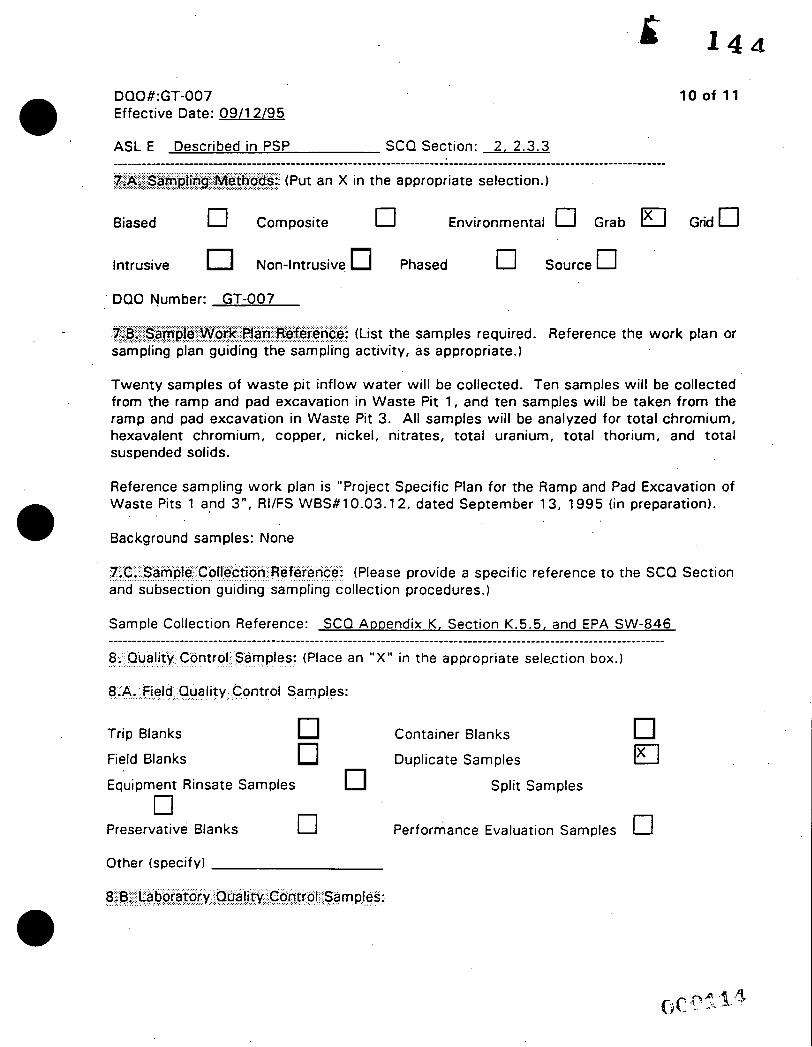
DQO #:GT-007 0 Effective Date: 09/12/95 10 of 11
Intrusive Non-Intrusive Phased 0 Source 0 DQO Number: GT-007
(List the samples required. Reference the work plan or sampling plan guiding the sampling activity, as appropriate.)
Twenty samples of waste pit inflow water will be collected. Ten samples will be collected from the ramp and pad excavation in Waste Pit 1, and ten samples will be taken from the ramp and pad excavation in Waste Pit 3. All samples will be analyzed for total chromium, hexavalent chromium, copper, nickel, nitrates, total uranium, total thorium, and total suspended solids.
Reference sampling work plan is "Project Specific Plan for the Ramp and Pad Excavation of Waste Pits 1 and 3 " , RI/FS WBS#10.03.12, dated September 13, 1995 (in preparation). 0 Background samples: None
7.C. Sample Collection Reference: (Please and subsection guiding sampling collection
provide a specific reference to the SCQ Section procedures.)
Sample Collection Reference: SCQ Amendix K, Section K.5.5, and EPA SW-846
8.,Quality. . . . . . . . . . . . . . . . . . Control-. . . . . . . . . . . Samples: . . . . (Place an "X" in the appropriate sele-ction box. 1 ....................................................................................................................
8.A. Field Quality Control Samples:
Trip Blanks Container Blanks
Field Blanks Duplicate Samples Ix1
cl Performance Evaluation Samples cl Equipment Rinsate Samples Split Sam pies
Preservative Blanks
Other (specify)
0
DO0 k GT-007 Effective Date: 09/12/95
Method Blank . ' O Matrix Duplicate/Replicate
Matrix Spike 0 Surrogate Spikes'
11 of 11
Other (specify)
9;F ._... .. ....,....... ..,,,5:&&e~; ..... I .................. Please provide any other germane information that may impact the data quality or gathering of this particular objective, task or data use.
AlTACHMENT D
WASTE PIT EXCAVATIONS MAP
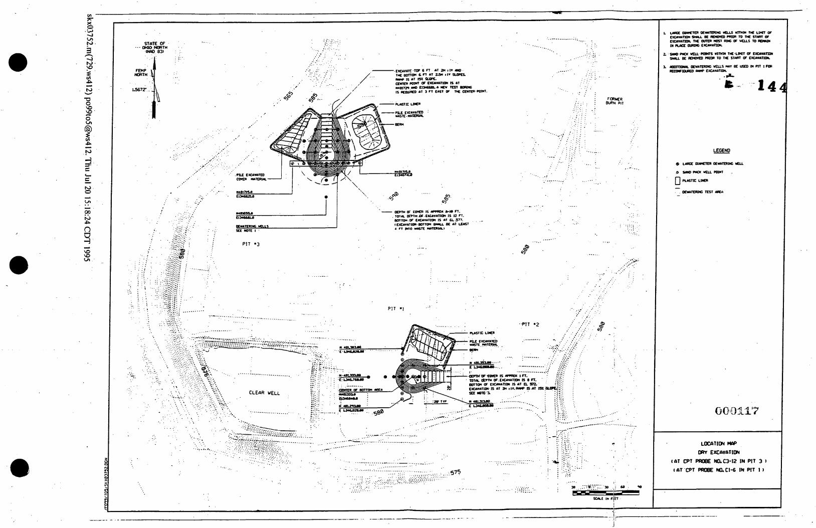
I . . .. .---- _. . _. ..... .
- . . . . : . . . . . . . ..: * . ....... . . . . . . . I /
...__, .. . . _ .
. . .
..... ........ ........ . . . . . . . . . . . . . . . . . .... . .
. . . . . . .
. . . . . .
. . . . . . . . . . . . . . .:
. . . . . . . . . . . . . - . . . . . . . . . . . . . . . . . . . . . . . . . . . . . . ....... ..... - . E r c A v ~ . T O P mol sF1 6 n a1 a1 m S I V :I. pogz m . _, . . . . . . . . . . . . . . . . .__ . . , :. . . . . . . . . . a r c a a r s x -
~ r m a pear Q t.uunltoc I AT . . . _ . . /.-. . . . - . _
. . . . . . . . . . . . .
. . . . . . . I
.m.
........ .. . . . . . . . . ..... . . . . . . . . . . . . . . . . . .
. . . . . . . ... . . . . . . . . . .....
. . . F O R Y E R
PIT
. .- . . . . . . . . . . . .
. . . .
. . . . LECEM)
. . . . . . ..-..._
e .
. . . . _. . . . . . ... . . . . . .
._ - .. - : : - . - . .
..... $.
. . . .
. . . ..: . '
. _ _ . . , .... . .
. . . . . . . . . . . . . . .
. - . ._.. : :.:.. . ..:.
. . i . . . . . . .:. . .'.:, , ....... .....
8 . ... ....... : .. .*. : I* .: .. f . .
. . . . . . . . . . : .: ,
...... . . . . . . . . . . . . . . . . . . . . . . . . . , : . . . . .
. . . . . . . . .
..... _... . . ............. .
. . . . . . . .... . . . . . . . . . . , , . '.. . . . . ,._ . . . . - . . , ' . . . . .
. . - . : : ' :
PIT '1 ......... ..... ..... .................. . . ,.- ....
. . . ...... . . . . . . . . . . . .........
. ,. . . . . . . . . . . e9 . . . : . ,;;. ,:. .;a I
. . . . . . . . . . . . . . . e : . . - . . . . . . . ......... -. . . . . . . . . . . . . . . . . . . . .
ATTACHMENT E
ENVIRONMENTAL MEDIA SAMPLING PLAN

-.
i 1 4 4
DEWATERING EXCAVATION EVALUATION PROGRAM RAMP AND PAD EXCAVATION OF WASTE PITS 1 AND 3 - SAMPLE COLLECTION
AND SHIPMENT PREPARATION 10.03.12
A. ldentifvina Information
B. Samolina Information a
Project Name: DEEP RAMP AND PAD EXCAVATION OF WASTE PITS 1 AND 3 Plan No.: 10.03.1 2 Material DescriptiodMatrix Code(s1: Tank Contents (Water) (M300) Number of Sampling Containers: 50 Material Type: water Source Code: Waste Pits 1 and 3 Material Evaluation Form #: N/A Sampling Location: Frac. Tanks holding pit pumpage from Waste Pits 1 and 3 Process Knowledge: Total uranium average from three Pit 1 monitoring wells is 5057 pg/l; total uranium average from three Pit 3 monitoring wells is 3139 &I, (source, Integrated Preliminary Hazard Assessment, Dewatering Excavation Evaluation Program (DEEP) Phases 2, 3, and 4", dated 12/1/94.
General: Material collected will be transferred from a 55-gallon drum Preservation Method: See Table 1 Holding Times: See Table 1 Sample Technique: Material will be collected from frac. tanks wi th a clean liquids
container. An EFO Lead Technician may select an alternative sampling technique, i f warranted.
Number of Drums to be transferred: N/A Composite Samples: N/A Visual Inspection Performed?: Yes Field Contact: Jim Hey/Dan Stropes, 648-4765/648-3030 Send Results to: Jim Hey/Dan Stropes Charge NoJProject Manager: 1 DCA2NVilly Benson Required QC Samples: 1 duplicate sample every 1 0 samples, 1 matrix duplicate/replicate per 20 samples. Receiving Facility NRC License Number: N/A
CRUl IWMPDFS.PSP/9/13/95 a
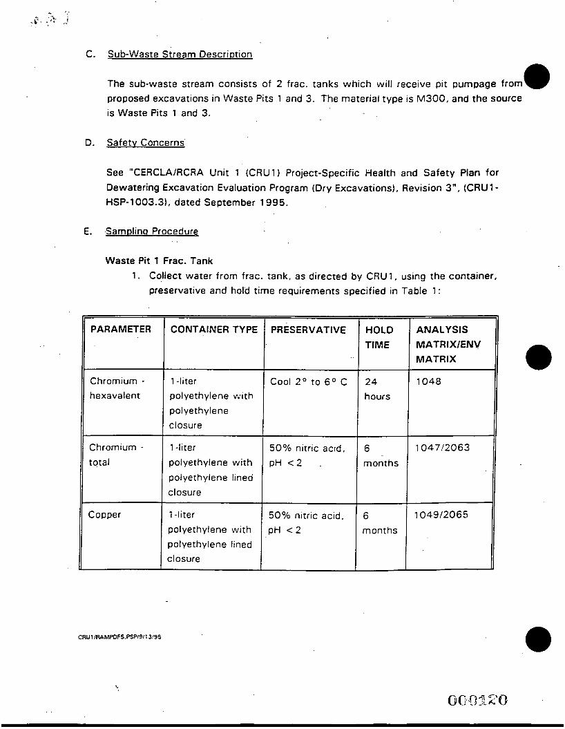
C.
D.
E.
PRESERVATIVE
Sub-waste Stream Descriotion
The sub-waste stream consists of 2 frac. tanks which will receive pit pumpage from proposed excavations in Waste Pits 1 and 3. The material type is M300, and the source is Waste Pits 1 and 3.
HOLD ANALYSIS TIME MATRIX/ENV
MATRIX
Safetv Concerns'
PARAMETER
Chromium - hexavalent
Chromium - total
Copper
See "CERCLA/RCRA Unit 1 (CRU1) Project-Specific Health and Safety Plan for Dewatering Excavation Evaluation Program (Dry Excavations), Revision 3", (CRU 1 - HSP-1003.31, dated September 1995.
CONTAINER TYPE
1 -liter
pol yet h y I en e vv i t h polyethylene closure
1 -liter
polyethylene with polyethylene lined closure
1 -liter
polyethylene with polyethylene lined closure
Samolina Procedure
I
Waste Pit 1 Frac. Tank 1. Collect water from frac. tank, as directed by CRU 1, using the container,
preservative and hold time requirements specified in Table 1 :
50% nitric acid, p H c 2 .
6 1047/2063
months
50% nitric acld, pH c 2
Cool 2 O to 6O C I 24 1 1048
6 1049/2065
months
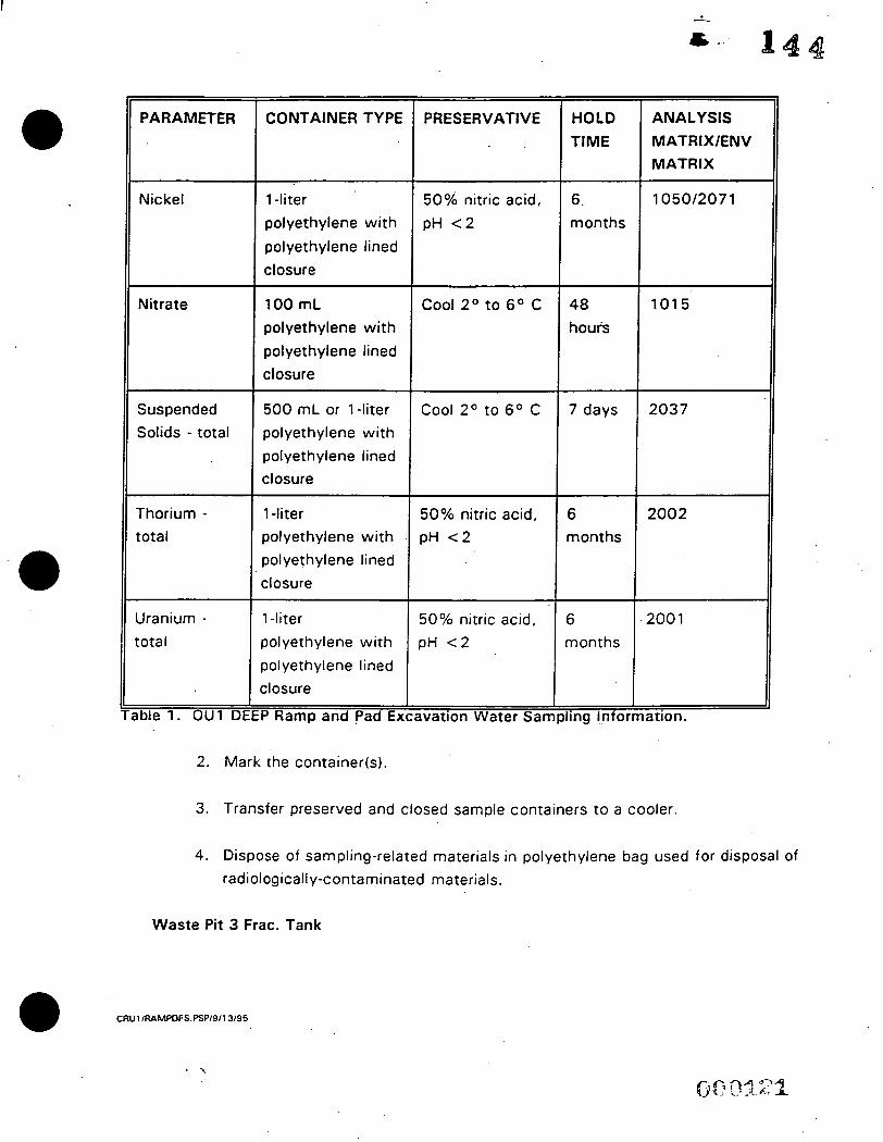
PARAMETER
50% nitric acid, pH < 2
Cool 2 O t o 6 O C
Nickel 6. 1050/2071 months
48 1015 Nitrate
Cool 2 O to 6 O C Suspended Solids - total
7 days 2037
Thorium - total
5 0 % nitric acid, pH < 2
Jranium - :otal
6 2002 months
lble 1. O U l D,
50% nitric acid, pH < 2
CONTAINER TYPE
6 .200 1
months
1 -liter polyethylene with
polyethylene lined closure
100 mL polyethylene with polyethylene lined closure
500 mL or l - l i ter polyethylene with polyethylene lined closure
1 -liter polyethylene with
polyethylene lined closure
1-liter .
Dolyethylene with
Dolyethylene lined :losure I
I
P Ramp and Pad €XI
MATRlXlENV MATRIX
hours
I I
iva t i on Water S am pl i ng Inform a t i o n .
2. Mark the container(s1.
3. Transfer preserved and closed sample containers to a cooler.
4. Dispose of sampling-related materials in polyethylene bag used for disposal of radiologically-contaminated materials.
Waste Pi t 3 Frac. Tank
CRUl IRAMPOFS.PSP/9/13/95 0
. 1. Collect water from frac. tank as directed by CRUI, using the container, preservative and hold time requirements specified in Table 1.
2. Mark the container(s1.
3. Transfer preserved and closed sample containers to a cooler.
4. Dispose of sampling-related materials in polyethylene bag used for disposal of radiologically-contaminated materials.
- F. ShiDDina Information
The water samples shall be delivered' t o the FERMCO Analytical Laboratory.
A n
Authorized Sign a tfle /D a t e Approved/Date .