transnational access procedure and general rules · 2016-11-24 · erigrid ga no: 654113 31/10/2016...
TRANSCRIPT

ERIGrid GA No: 654113 31/10/2016
TA Procedure and Rules Revision / Status: v03 1 of 127
European Research Infrastructure supporting Smart Grid Systems Technology Development, Validation and Roll Out
TRANSNATIONAL ACCESS PROVISION
Transnational Access Procedure and General Rules
Grant Agreement No: 654113
Funding Instrument: Research and Innovation Actions (RIA) – Integrating Activity (IA)
Funded under: INFRAIA-1-2014/2015: Integrating and opening existing national and regional research infrastructures of European interest
Starting date of project: 01.11.2015
Project Duration: 54 month
Project co-funded by the European Commission within the H2020 Programme (2014-2020)

ERIGrid GA No: 654113 31/10/2016
TA Procedure and Rules Revision / Status: v03 2 of 127
Table of contents
Executive Summary ........................................................................................................................ 6
1 Introduction .............................................................................................................................. 7
1.1 Purpose of the Document ................................................................................................. 8 1.2 Scope of the Document .................................................................................................... 8 1.3 Structure of the Document ................................................................................................ 8
2 Eligibility of the User Groups .................................................................................................... 9
3 Transnational Access procedure ............................................................................................ 10
3.1 STEP 1: Publications of the Call for Proposals................................................................ 10 3.2 STEP 2: Submission of the User Proposals .................................................................... 11 3.3 STEP 3: Evaluation of the User Proposals ...................................................................... 11 3.4 STEP 4: Selection of the Proposal and Notification to the User Group ............................ 13 3.5 STEP 5: Access to the Research Infrastructure .............................................................. 13 3.6 STEP 6: Dissemination and publication of the project results .......................................... 14
4 Reimbursement of the access expenses ................................................................................ 15
Annexes ........................................................................................................................................ 16
5.1 List of Figures ................................................................................................................. 16 5.2 Annex 1: Research Infrastructure descriptions and transnational access conditions ....... 17 5.3 Annex 2: User project proposal template ...................................................................... 122 5.4 Annex 3: Template for the declaration of TA expenses by the user............................... 125 5.5 Annex 4: Essential information to be included in the access Contract ........................... 127
ERIGrid GA No: 654113 31/10/2016
TA Procedure and Rules Revision / Status: v03 3 of 127
Abbreviations AC Alternating Current
AMI Advanced Metering Infrastructure
API Application Programming Interface
CEN Comité Européen de Normalisation (European Committee for Standardization)
CENELEC Comité Européen de Normalisation Électrotechnique (European Committee for Electrotechnical Standardization)
CHAdeMO CHArge de MOve (EV charging protocol)
CHIL Controller Hardware-in-the-Loop
CHP Combined Heat and Power
CIGRÉ Conseil International des Grands Réseaux Electriques (Council on Large Electric Systems)
CIM Common Information Model
COSEM Companion Specification for Energy Metering
CPU Central Processing Unit
DAQ Data Acquisition
DC Direct Current
DG Distributed Generation
DER Distributed Energy Resource
DLMS Device Language Message Specification
DSO Distribution System Operator
DVR Dynamic Voltage Restorer
EC European Commission
EEGI European Electricity Grid Initiative
EERA European Energy Research Alliance
EMF Electro-magnetic Field
ES Energy Saving
ETSI European Telecommunications Standards Institute
EU European Union
EV Electric Vehicle
EVSE Electric Vehicle Supply Equipment
FACTS Flexible AC Transmission System
FPGA Field Programmable Gate Array
FRT Fault-Ride-Through
GIS Geographic Information System
GOOSE Generic Object Oriented Substation Events
GPRS General Packet Radio Service
GPS Global Positioning System
HIL Hardware-in-the-Loop
HV High Voltage

ERIGrid GA No: 654113 31/10/2016
TA Procedure and Rules Revision / Status: v03 4 of 127
HVDC High-Voltage Direct Current
IA Integrating Activity
ICT Information and Communications Technology
IEC International Electrotechnical Commission
IED Intelligent Electronic Device
IEEE Institute of Electrical and Electronics Engineers
ISGAN International Smart Grid Action Network
IT Information Technology
I/O Input/Output
LAN Local Area Network
LV Low Voltage
LVRT Low-Voltage Ride Through
MG Motor-Generator
MPPT Maximum Power Point Tracker
MV Medium Voltage
NA Networking Activity
NTP National Technology Platform
OLTC On-Load Tap Changer
PC Personal Computer
PHIL Power Hardware-in-the-Loop
PMU Phasor Measurement Unit
PLC Power Line Communication
PLC Programmable Logic Controller
PQ Power Quality
PV Photovoltaic
RCP Rapid Control Prototyping
RES Renewable Energy Sources
RI Research Infrastructure
RIA Research and Innovation Actions
RP Responsible Person
RPM Revolutions per minute
RT Real Time
RTD Research and Technical (or Technological) Development
RTS Real-Time (Digital) Simulator
RTU Remote Terminal Unit
RUE Rational Use of Energy
R&D Research and Development
SCADA Supervisory Control And Data Acquisition
SGAM Smart Grid Architecture Model

ERIGrid GA No: 654113 31/10/2016
TA Procedure and Rules Revision / Status: v03 5 of 127
SIRFN Smart Grid International Research Facility Network
STATCOM Static Synchronous Compensator
TA Transnational Access
TSO Transmission System Operator
UPS Uninterruptible Power Supply
USP User Selection Panel
VPP Virtual Power Plant
V2G Vehicle-to-Grid
ERIGrid GA No: 654113 31/10/2016
TA Procedure and Rules Revision / Status: v03 6 of 127
Executive Summary The core of the ERIGrid project is the transnational access to integrated research infrastructure, operated at 21 distributed installations, located in 11 countries. The ERIGrid TA activity, placed at the disposal of (mainly) the European research community, includes “free of charge” access to these infrastructures, technological and scientific support and funding to cover travel and accom-modation during stays. This document specifies the general rules of the ERIGrid TA scheme, describing the entire access procedure, the public calls, proposal evaluation and selection and hosting of researcher groups at the facilities on offer. Moreover, the document indicates the basic provisions for the dissemination of the results of implemented user projects. The descriptions of the offered Research Infrastruc-tures, along with the corresponding TA conditions, are provided as well. Further information on the ERIGrid project and description of the offered Research Infrastructures is available at the ERIGrid website (https://erigrid.eu).
ERIGrid GA No: 654113 31/10/2016
TA Procedure and Rules Revision / Status: v03 7 of 127
1 Introduction
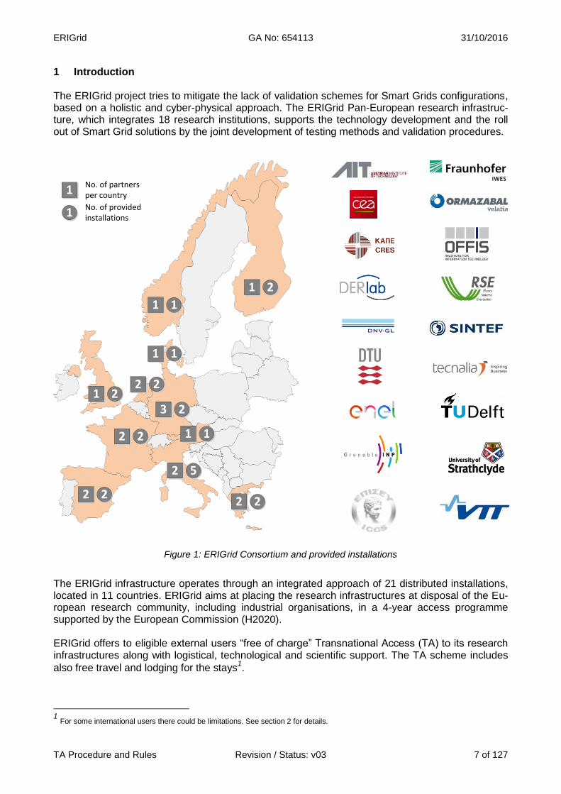
The ERIGrid project tries to mitigate the lack of validation schemes for Smart Grids configurations, based on a holistic and cyber-physical approach. The ERIGrid Pan-European research infrastruc-ture, which integrates 18 research institutions, supports the technology development and the roll out of Smart Grid solutions by the joint development of testing methods and validation procedures.
Figure 1: ERIGrid Consortium and provided installations
The ERIGrid infrastructure operates through an integrated approach of 21 distributed installations, located in 11 countries. ERIGrid aims at placing the research infrastructures at disposal of the Eu-ropean research community, including industrial organisations, in a 4-year access programme supported by the European Commission (H2020).
ERIGrid offers to eligible external users “free of charge” Transnational Access (TA) to its research infrastructures along with logistical, technological and scientific support. The TA scheme includes
also free travel and lodging for the stays1.
1 For some international users there could be limitations. See section 2 for details.
1
1
No. of partners per country
No. of provided installations
1 1
2 2
2 5
2 2
2 2
1 2
1 1
1 2
1 1
2 2
3 2
ERIGrid GA No: 654113 31/10/2016
TA Procedure and Rules Revision / Status: v03 8 of 127
1.1 Purpose of the Document
The objective of this document is to become the basic guide for those Users Groups who are think-ing of using the ERIGrid transnational access and benefiting from this opportunity supported by the European Commission (H2020). An updated version of the document might be necessary during the execution phase of the transnational access as further aspects are brought to light by potential applicants and granted users.
1.2 Scope of the Document
The document has been prepared following a didactic approach that covers the eligibility of the us-ers and the end-to-end procedure to be followed in the ERIGrid transnational access programme: from the call announcement to the mandatory dissemination of the user project results.
This guide provides also the descriptions of the research infrastructures offered by ERIGrid and the concrete transnational access conditions applicable to the individual installations. As part of the streamlined process, two templates are also included: a first one for the user project proposal and second one for the declaration of TA expenses by the User Group.
Even though some basic contractual indications are contained as a reference in this document, the actual contract template is out of scope for this guide and will be issued separately.
1.3 Structure of the Document
The document has two main chapters: Chapter 2 on the eligibility conditions to be fulfilled by the users of the TA programme, and Chapter 3 on the step-by-step access procedure. Since the reim-bursement of the TA expenses is a critical point for the users, Chapter 4 provides the basic treat-ment of this issue.
For the sake of clarity, the comprehensive descriptions of the research infrastructures and the helpful templates are presented within the annexes of this document.

ERIGrid GA No: 654113 31/10/2016
TA Procedure and Rules Revision / Status: v03 9 of 127
2 Eligibility of the User Groups
Transnational access (TA) is provided to selected “users” and “user groups” (teams of one or more researchers led by a User Group Leader). The selection will be done through the evaluation of the received user project proposals by an independent review panel of experts from different domains that are involved in smart grids (power systems, ICT, cybersecurity, etc.).
Funding is for “transnational access” i.e. within another country that is not the country of origin of the user. The User Group Leader and the majority of the User Group members should work in an institution/SME located in a different country to the country where the infrastructure/installation is located. For multi-site projects this rule applies to all sites to be accessed.
The ERIGrid transnational access is open to researchers that are primarily from organizations (this includes SMEs and larger industries) located in an EU Member State.
Limited access is also available to applicants from non-EU countries (“third countries”): the limita-tion is not on the number of User Groups from these countries but on the amount of access that can be provided by ERIGrid: access for user groups with a majority of users working in third coun-tries is limited to 20% of the total amount of units of access provided under the grant. Third coun-
tries include H2020 Associated Countries2 (Albania, Bosnia & Herzegovina, Faroe Islands, Former
Yugoslav Republic of Macedonia, Georgia, Iceland, Israel, Moldova, Montenegro, Norway, Servia,
Switzerland –partial association3-, Tunisia, Turkey, and Ukraine), and other developing countries
4.
Industrialised countries from non-EU or Associated countries can apply for TA but travel and sub-sistence expenses will be covered subject to budget availability, especially in the later stages of the
project. The general H2020 conditions for International Cooperation5 and H2020 rules apply for
formal eligibility.
Only User Groups that agree to disseminate the results that they have generated under the project are eligible to benefit from access to the infrastructure free of charge, except for SMEs and indus-trial users, for which special confidentiality provisions may be needed. Young scientists at the start of their careers and female researchers will be positively considered.
The duration of the stay at a Research Infrastructure will normally be 1-4 weeks but in some cases longer stays of up to 3 months may also be justified.
2 http://ec.europa.eu/research/participants/data/ref/h2020/grants_manual/hi/3cpart/h2020-hi-list-ac_en.pdf
3 http://ec.europa.eu/research/participants/data/ref/h2020/other/hi/h2020-hi-swiss-part_en.pdf
4 http://ec.europa.eu/research/participants/data/ref/h2020/other/wp/2016-2017/annexes/h2020-wp1617-annex-a-countries-rules_en.pdf
5 http://ec.europa.eu/research/participants/docs/h2020-funding-guide/cross-cutting-issues/international-cooperation_en.htm

ERIGrid GA No: 654113 31/10/2016
TA Procedure and Rules Revision / Status: v03 10 of 127
3 Transnational Access procedure
This section describes the steps of the entire procedure, detailing how the transnational access in ERIGrid will be implemented through successive public calls. It provides the criteria for the as-sessment and selection of proposals by the User Selection Panel (USP) and settles the general rules for the development of the selected user projects and the dissemination of the results. In ad-dition, it defines the general contractual conditions pertaining to the researcher stay at the infra-structures. Further elaboration and specifics will be detailed using a contract.
The general timeline is shown in the next figure below. As a reference, the duration of the call and the associated user stays will last for around 8 months, with the following main time periods:
The Call will remain open for 3 months.
The received proposals will be evaluated within one month after the closing date of eachcall.
The stay period depends on the user project: 1-4 weeks typically and limited to a maximumof 3 months if well justified.
Finally, the User Group has a month to carry out the mandatory reporting of the project.
Figure 2: Call reference timeline
3.1 STEP 1: Publications of the Call for Proposals
Every 6 months a Call for Proposals will be launched by ERIGrid for transnational access to con-duct experiments at the Research Infrastructures listed in Appendix 1.
The dissemination of the transnational access calls will be done through the ERIGrid website (erigrid.eu, where a dedicated TA section has been created), social networks, advertisement through different channels (posters, flyers, press releases, ERIGrid partners’ web pages, etc.), publications at conferences, workshops and journals, and direct contact with potential users.
Topics targeted by the Calls:
The Calls for Proposals will be targeted to research and development of Smart Grid concepts and configurations and to testing and validation methods and tools following a holistic approach.
Future electrical networks will integrate higher shares of fluctuating renewable energy, distributed energy resources at all voltage levels, active prosumers, electrical vehicles, demand side man-agement programmes, etc. Besides the power system components, like the grid infrastructure, storage, generation, consumption, etc., it also comprises ICT, cyber-security, markets, regulation, etc. Any project proposal covering these broad and complex themes, will fall into the ERIGrid TA scope and may be eligible.
1 2 3 4 5 6 7 8 9
TIMELINE (months)
Call opening Call closing Proposals evaluation end
PROPOSALS EVALUATION STAYS PERIOD
CALL ANNOUNCEMENT
RECEPTION OF PROPOSALS
Proposals evaluation start
End of stays of Call
Deadline forstays reporting
STAYS REPORTING
ERIGrid GA No: 654113 31/10/2016
TA Procedure and Rules Revision / Status: v03 11 of 127
In this context, those proposals contributing to the improvement of the services provided by the infrastructures, the harmonisation and optimization of methodologies, and the reinforcement of the partnership with industry will receive a special consideration. The experimental research on the selected research topics must be implemented in one (or sever-al) of the offered research infrastructures listed in Appendix 1, therefore technical feasibility will be checked in advance by the corresponding research infrastructures based on the available equip-ment/facility and offered services. 3.2 STEP 2: Submission of the User Proposals In response to the Calls, User Groups will submit their project proposals to ERIGrid. The submis-sion will be done electronically (using the ERIGrid TA email address, the on-line tool or the on-line application form) before the Call deadline. Proposal documents must be completed using the pro-posal template (Appendix 2), available on the ERIGrid website. The User Group preparing the proposal will indicate the preferred infrastructures (one, two or three options are allowed) where the experimental research will be carried out. These preferences will be considered, to the extent possible, during the evaluation process. Normally (it is not mandatory but recommended for a successful proposal), before submission of the application form, the User Group will contact the preferred infrastructure/s to check the prelimi-nary availability of the facilities and feasibility of the experiments, and to clarify the research objec-tives and access conditions. 3.3 STEP 3: Evaluation of the User Proposals The selection of researchers or research teams will be carried out through an independent peer-review evaluation of their research projects. The evaluation of the user project proposals will be done in two phases: (1) pre-screening, and (2) full evaluation. The entire evaluation process is expected to be completed within one month after the deadline for the submission of proposals.
Pre-screening 3.3.1 The pre-screening is the first assessment of the technical and economic feasibility of the received proposal done by the three Research Infrastructures selected (preferred) by the User Group. Technical problems, risks and related cost will be considered. No further evaluation criteria will be employed at this stage. The pre-screening process will start as soon as a proposal is received, even before the Call is closed. In this phase, the selected infrastructures may suggest/request modifications to the pro-posal in order to ensure feasiblity and pass the pre-screening (in any case, the improved proposal resulting from this interaction must be submitted by the User Group before the Call deadline). If the proposal is not feasible at any of the three selected infrastructures, the ERIGrid TA Manager will circulate it to the rest of the RIs so they can assess it for feasibility at their own RI. The pro-posal will be assigned to one of the research infrastructures, not initially selected by the User Group, but able to implement the user project. If more than one RI can develop the project, the Us-er Group will be contacted to choose. If in the end, the proposal (even modified or adapted) cannot be implemented at any RI, it will be rejected. The aim of pre-screening is to filter out and avoid the unnecessary work by the User Selection Panel in evaluating and approving a proposal that cannot be implemented due to technical or eco-

ERIGrid GA No: 654113 31/10/2016
TA Procedure and Rules Revision / Status: v03 12 of 127
nomical infeasibility at the selected infrastructures (or even in any ERIGrid infrastructure). The pre-screening is expected to run smoothly if preliminary contact has been established between the proposing User Group and the selected infrastructures. On conclusion the Pre-screening phase, each feasible proposal will be linked to a research infra-structure, where the project can be carried out. At this point, the proposal is ready for the full eval-uation phase.
Full evaluation 3.3.2 All received proposals that pass the pre-screening will be subsequently fully evaluated. This will be performed by the User Selection Panel (USP). The USP is a group consisting of experts from with-in and outside ERIGrid partner organisations with diverse profiles (academia, industry) and cover-ing the different domains of the smart grid arena (power systems, ICT, etc.). The concrete experts for the evaluation of each proposal will be appointed by the ERIGrid TA Manager and the ERIGrid Project Coordinator depending on the proposal topic and the availability of the USP members. The ERIGrid TA Manager and the ERIGrid Project Coordinator will not participate in the proposal eval-uation but shall guarantee the compliance of the proposal with the eligibility rules of the transna-tional access. Each USP member evaluating a proposal will assign the following score: A for Excellent (16-20) B for Good (11-15) C for Fair (6-10) D for Poor (0-5) Evaluation Criteria The criteria for the assessment of the proposals successfully pre-screened (i.e. technically feasi-ble) are the following:
a) Scientific/Technical merit (score: 0-5): scientific and technical relevance, originality and innovation, methodology.
b) Improve know-how and capacity of the Research Infrastructure (score: 0-5): improve-ment of know-how within the Research Infrastructures, enhancement of RI technologies and methods, alignment with ERIGrid scenarios/use cases/test cases, synergies with other projects and cooperation with other infrastructures.
c) Compliance with EU policies and priorities (score: 0-5): compliance with European RTD
policies and priorities. Social impact. Impact on EU industry (e.g. standardization and com-petitiveness). Sustainable growth interest. New users, young researchers, female re-searchers.
d) General quality of the proposal (score: 0-5): completeness and organization of the pro-
posal, clear definition of the objectives and expected results, relevance of the proposed dissemination actions, justified requested amount of access.
Also in this phase, the USP may provide comments and suggest modifications to improve the pro-posal and make it ready for resubmission within the call deadline or to future calls.
ERIGrid GA No: 654113 31/10/2016
TA Procedure and Rules Revision / Status: v03 13 of 127
3.4 STEP 4: Selection of the Proposal and Notification to the User Group All the proposals will be ranked based on the scores assigned by the USP. D-scored proposals will be normally rejected. Proposals resubmitted, that may have been unsuccessful in previous calls, will be evaluated as new ones. The User Group of each proposal, will be formally notified of the evaluation result by the ERIGrid TA Manager at the end of the evaluation period (one month after the Call deadline). This result will be accompanied with a short Review Report with comments and possibly suggestions for im-provement. If due to technical/economic feasibility or laboratory availability none of the RIs selected by the us-er group can be allocated, a different RI may be offered. If this is the case, the User Groups can (1) withdraw the proposal, (2) update and resubmit the proposal as a new one in one of the next calls, (3) remain with the assigned score for the next Call, when it will be ranked in a new list with the new proposals, or (4) accept the alternative RI suggested by the TA manager. Normally this situa-tion will be communicated to the User Group and clarified during the Pre-screening phase. 3.5 STEP 5: Access to the Research Infrastructure When a proposal is accepted, a focussed interaction between the proposing User Group and the host infrastructure starts. The estimated access period indicated in the proposal must be confirmed and agreed between the User Group and the host Research Infrastructure. Normally, the access period must be allocated to a date within the next 3 months, following the agreement of the tech-nical details for executing the experiments and fulfilment of administrative issues.
Signature of the Contract 3.5.1 Before the commencement of the project, a contract must be signed between the hosting research infrastructure and the User Group. The basic template contract will provided for use in all ERIGrid TA projects as a reference model, but extensions or specific modifications may be introduced by each research infrastructure for the project, as necessary; the essential information is outlined in Annex 4. The Contract will have a Technical Annex that describes the test programme to be performed dur-ing the access period in the Research Infrastructure. This Annex must be coherent with the pro-posal (even though some adjustments in practice are allowed). Significant modifications of the technical content or the access conditions (e.g. number of access days) with respect to the planned ones in the proposal should be checked with the ERIGrid TA Manager for approval.
Assistance to the User Group 3.5.2 Each Research Infrastructure must nominate a Responsible Person (RP) for each accepted User Project (linked to a proposal). The RP is in charge of supervising the experimental activity at the installation (including the safety matters), and supporting the User Group in all technical, adminis-trative and logistic needs. The RP is also the reference person for reporting to ERIGrid on the state of the activity running at the Research Infrastructure.
Notification of the use of the installation/infrastructure 3.5.3 At the end of the stay at the Research Infrastructure, the User Group must declare the use of the installations by signing a specific form (attached to the Contract) and indicating the total number of “access days” (days of real use of the installation) and the total number of “stay days” (which in-cludes the access days in the laboratory but normally also the days working in the office of the host, weekend days if applicable, etc.) of each member of the User Group.

ERIGrid GA No: 654113 31/10/2016
TA Procedure and Rules Revision / Status: v03 14 of 127
3.6 STEP 6: Dissemination and publication of the project results The ERIGrid access opportunity has some dissemination commitments, specified in the access Contract. Firstly, with the aim of improving the transnational access quality, two questionnaires must be filled: the first one for collecting the user feedback on the access and the stay at the infra-structure, and a second one regarding the host experience to be filled by the host infrastructure. Secondly, an extended abstract of the user project must be prepared by the User Group to be pub-lished as a “Project Fact Sheet”. Further to this, a detailed Technical Report is also mandatory, de-scribing the objectives and experiments, and comprising the obtained results and conclusions. In case the Technical Report contains confidential information (for example, for some industrial us-ers), special provisions will be taken by ERIGrid and the European Commission: the Technical Re-port will not be made publicly available (it will be distributed just to the hosting research infrastruc-ture, the ERIGrid project coordinator, and the European Commission). The three mandatory dissemination documents (questionnaire, extended abstract and technical report) must be prepared by the User Group and submitted to the ERIGrid TA Manager within one month after the end of the stay. In addition, the User Group is obliged to give detailed information to the ERIGrid TA Manager about future reports, papers, conference presentations, etc., preferably open (otherwise it must be justified), as soon as they are published in order to provide evidence of the soundness of the scien-tific work performed at the Research Infrastructure under this opportunity. Whenever possible ERIGrid would like to receive any publication made as a result of this research to publish them in the website (provided that the full rights of the researchers are not affected and the copyright con-ditions are not violated: for example, pre-print or post-print copies could be acceptable for non-open access publications). Finally, a workshop on user projects will be organised by ERIGrid as a forum for sharing user ex-periences and lessons learnt. User Groups will have the opportunity to disseminate their investiga-tions, present their project results, and extend their contact network. Conditions of EU Horizon 2020 support for transnational access concerning publication The ERIGrid project reports to the European Commission will contain the names, home institutions and description of the work of the users. The ERIGrid website will publish a list of projects naming the researchers’ organizations, research project titles and short descriptions, and the facilities used. Users must also note that the EC has the right to publish the list of users. Publications (including presentations) which result from transnational access in ERIGrid shall dis-play the EU emblem and contain the acknowledgement: “This <insert here the type of research/result> has been <performed/achieved> using the ERIGrid Research Infrastructure and is part of a project that has received funding from the European Un-ion’s Horizon 2020 Research and Innovation Programme under the Grant Agreement No. 654113. The support of the European Research Infrastructure ERIGrid and its partner <name> is very much appreciated”. Publications must be in English (at least the first one associated to the access).

ERIGrid GA No: 654113 31/10/2016
TA Procedure and Rules Revision / Status: v03 15 of 127
4 Reimbursement of the access expenses The transnational access offered by ERIGrid covers the User Group’s expenses for travel and sub-sistence according to the H2020 rules and the host Research Infrastructure conditions (see Ap-pendix 1). Reasonable travel expenses (low-cost company, economy class and public transportation, when-ever possible) will be reimbursed with the presentation of the corresponding invoices/receipts. For the daily subsistence expenses (accommodation in conventional –not luxury– hotels or equivalent lodging, and meals in regular restaurants), two possibilities (or a combination) are allowed depend-ing on the host infrastructure conditions:
“Payment by invoice”: the User Group will get the refund of the subsistence costs after the stay, when declaring the incurred expenses and presenting the invoices/receipts (same mechanism than the reimbursement of the travel expenses); normally, the host infrastruc-ture indicates a reference maximum amount per person for the daily subsistence fee as an indication for the users.
“Daily allowance”: each user receives a per-day pocket money for each day of stay accord-ing to the host infrastructure conditions to pay for all the daily subsistence expenses.
For the declaration of the expenses the User Group can use the template included in Appendix 3 (which can be downloaded from the ERIGrid website) and must send it to the host infrastructure for approval and refund.

ERIGrid GA No: 654113 31/10/2016
TA Procedure and Rules Revision / Status: v03 16 of 127
Annexes
5.1 List of Figures
Figure 1: ERIGrid Consortium and provided installations ................................................................ 7 Figure 2: Call reference timeline ................................................................................................... 10 Figure 3: AIT SmartEST facility ..................................................................................................... 18 Figure 4: AIT SmartEST research and testing facility for smart grid systems and components ..... 19 Figure 5: HIL and smart metering capabilities of SmartEST .......................................................... 19 Figure 6: Schematic overview of the SmartEST lab ...................................................................... 20 Figure 7: CEA Ines (Le Bourget-du-Lac, France) .......................................................................... 25 Figure 8: Facilities at CEA Ines ..................................................................................................... 26 Figure 9: Facilities at CEA Ines ..................................................................................................... 26 Figure 10: Facilities at CEA Ines ................................................................................................... 26 Figure 11: Overview of microgrid’s main components of DG-Lab at CRES (Pikermi, Greece) ...... 30 Figure 12: Overview of microgrid’s main configuration of DG-Lab ................................................. 31 Figure 13: Snapshot of the main screen of the supervisory control application in DG-Lab ............ 31 Figure 14: Long-term test of PV modules in DG-Lab ..................................................................... 32 Figure 15: Programmable Grid simulator and load-bank control in DG-Lab ................................... 33 Figure 16: Battery testers in DG-Lab ............................................................................................. 34 Figure 17: DG-Lab facilities ........................................................................................................... 34 Figure 18: FPGL at DNV GL (Arnhem, the Netherlands) ............................................................... 38 Figure 19: Different AC power quality phenomena available at the FPGL infrastructure ............... 40 Figure 20: Layout of the electrical grid in SYSLAB ........................................................................ 45 Figure 21: Overview of the SYSLAB facility on Risø campus ........................................................ 45 Figure 22: G2Elab facilities (Grenoble, France) ............................................................................ 51 Figure 23: G2Elab facilities (Grenoble, France) ............................................................................ 51 Figure 24: G2Elab facilities (Grenoble, France) ............................................................................ 52 Figure 25: G2Elab facilities (Grenoble, France) ............................................................................ 52 Figure 26: G2Elab facilities (Grenoble, France) ............................................................................ 53 Figure 27: G2Elab facilities (Grenoble, France) ............................................................................ 53 Figure 28: EESL Laboratory at ICCS-NTUA (Athens, Greece) ...................................................... 57 Figure 29: EESL Laboratory at ICCS-NTUA .................................................................................. 58 Figure 30: EESL Laboratory at ICCS-NTUA .................................................................................. 59 Figure 31: EESL Laboratory at ICCS-NTUA .................................................................................. 60 Figure 32: EESL Laboratory at ICCS-NTUA .................................................................................. 61 Figure 33: EESL Laboratory at ICCS-NTUA .................................................................................. 62 Figure 34: The main building of IWES-SysTec with the labs SysTec PNI and SysTec TPE .......... 66 Figure 35: View into the control room of the Lab SysTec PNI ....................................................... 67 Figure 36: Inside view into the Lab “SysTec PNI” .......................................................................... 68 Figure 37: MV Equipment under test: Power transformer with OLTC ............................................ 68 Figure 38: UDEX at ORMAZABAL Corporate Technology (Amorebieta, Spain) ............................ 71 Figure 39: UDEX at ORMAZABAL Corporate Technology ............................................................ 72 Figure 40: UDEX at ORMAZABAL Corporate Technology ............................................................ 73 Figure 41: UDEX at ORMAZABAL Corporate Technology ............................................................ 73 Figure 42: Real-time simulator at OFFIS ....................................................................................... 76 Figure 43: SESA-Lab at OFFIS ..................................................................................................... 78 Figure 44: OFFIS premises (Oldenburg, Germany) ....................................................................... 79 Figure 45: DER-TF at RSE (Milano, Italy) ..................................................................................... 82 Figure 46: DER-TF diagram .......................................................................................................... 83 Figure 47: LV DC Microgrid at DER-TF ......................................................................................... 83 Figure 48: Face-to-Face converter at DER-TF .............................................................................. 84 Figure 49: Domotic house at DER-TF ........................................................................................... 84 Figure 50: EV charging station at DER-TF .................................................................................... 84

ERIGrid GA No: 654113 31/10/2016
TA Procedure and Rules Revision / Status: v03 17 of 127
Figure 51: SW Interface at DER-TF .............................................................................................. 85 Figure 52: Smart network testing facility at SINTEF (Trondheim, Norway) .................................... 89 Figure 53: EV charging infrastructure at SINTEF .......................................................................... 89 Figure 54: NSGL concept at SINTEF ............................................................................................ 90 Figure 55: NSGL equipment at SINTEF ........................................................................................ 90 Figure 56: Microgrid of the Smart Grid Technologies Laboratory at TECNALIA (Derio, Spain) ..... 93 Figure 57: Electrical Vehicle platform at TECNALIA ...................................................................... 94 Figure 58: Smart Metering communication platform at TECNALIA ................................................ 94 Figure 59: Experimental set-up in the LV microgrid of TECNALIA ................................................. 95 Figure 60: Real Time Digital Simulator Laboratory at TUDelft (Delft, The Netherlands) ................ 98 Figure 61: Real Time Digital Simulator at TUDelft ......................................................................... 99 Figure 62: D-NAP Laboratory at the University of Strathclyde (Glasgow, United Kingdom) ......... 103 Figure 63: Power converters and controllable loads at D-NAP Laboratory .................................. 103 Figure 64: RTDS system at D-NAP Laboratory ........................................................................... 104 Figure 65: Acquisition system at D-NAP Laboratory .................................................................... 104 Figure 66: RTS and RTX units at D-NAP Laboratory .................................................................. 105 Figure 67: Communication emulation equipment at D-NAP Laboratory ....................................... 105 Figure 68: D-NAP facility ............................................................................................................. 106 Figure 69: PNDC facility (Glasgow, United Kingdom) .................................................................. 109 Figure 70: PNDC equipment ....................................................................................................... 110 Figure 71: PNDC equipment ....................................................................................................... 110 Figure 72: Acquisition system at PNDC ...................................................................................... 110 Figure 73: PNDC facility (Glasgow, United Kingdom) .................................................................. 111 Figure 74: VTT Multipower Laboratory (Espoo, Finland) ............................................................. 114 Figure 75: Communication testing architecture at Multipower Laboratory ................................... 115 Figure 76: Oulu Smart Grid Laboratory (Oulu, Finland) ............................................................... 119
5.2 Annex 1: Research Infrastructure descriptions and transnational access conditions
This Annex contains the descriptions of the Research Infrastructures included in the transnational access programme offered by ERIGrid. In addition to the description of the facilities, the transna-tional access conditions prescribed by each infrastructure are specified. This information can be also downloaded from the TA section of the ERIGrid website (https://erigrid.eu/).

ERIGrid GA No: 654113 31/10/2016
TA Procedure and Rules Revision / Status: v03 18 of 127
AIT Austrian Institute of Technology
1 Research Infrastructure
Name of Infrastructure/Installation Smart Electricity Systems and Technologies Labora-tory (SmartEST)
Location AIT – Vienna, Austria
Web Site www.ait.ac.at
2 Description of the Research Infrastructure The AIT SmartEST, located in Vienna, Austria, provides a multifunctional research, validation, and testing infrastructure allowing the testing of single devices as well as analysis of the interactions among multiple power system components – especially Distributed Energy Resource (DER)-based inverter systems – and the power grid under realistic, nearly real-world situations. The laboratory includes three configurable three-phase low-voltage grids; a high-bandwidth, programmable power grid simulator; several Photovoltaic (PV) array simulators; and an environmental test chamber for emulating various environmental conditions. This permits the validation and testing of DER-based inverter systems at full power under extreme temperature and humidity conditions and the investiga-tion of their interactions under various power grid conditions. The facility is capable of testing invert-ers, storage units, grid controllers, and Combined Heat and Power (CHP) units as well as charging stations/supply equipment for electric vehicles in the power range from a few kVA up to 1 MVA.
Figure 3: AIT SmartEST facility

ERIGrid GA No: 654113 31/10/2016
TA Procedure and Rules Revision / Status: v03 19 of 127
Figure 4: AIT SmartEST research and testing facility for smart grid systems and components
In addition, AIT SmartEST allows the real-time simulation of complex power grids and components as well as the coupling of this virtual environment with the laboratory grids. This kind of Hardware-in-the-Loop (HIL) setup lets researchers integrate real power system components into a virtual grid environment and test them as they interact with the grid under realistic conditions. Besides the HIL-based integration of power system components, Information and Communication Technology (ICT)/automation approaches, concepts, and developments can be integrated into the whole setup, allowing a comprehensive analysis of smart grid-related topics. The combination of a state-of-the-art testing infrastructure with HIL-based simulations (i.e., of the power system and ICT/automation infrastructure) provides cutting-edge testing capabilities for component manufacturers and network operators.
Figure 5: HIL and smart metering capabilities of SmartEST
hardware under test
(HUT)
signals
real time
computing
system
simulated
system
e-sTD
TVA(s)
ZB(s)
digital simulation
system
interface with
voltage amplifier
power

ERIGrid GA No: 654113 31/10/2016
TA Procedure and Rules Revision / Status: v03 20 of 127
Designed as a pure low-voltage research and testing environment, all AC buses are rated for op-eration at voltages of up to 480 V (line to line). The laboratory itself is supplied from the local 20 kV medium-voltage power grid via two independent medium- and low-voltage (MV/LV) transformers. The test facility has been used for comprehensive performance testing of DER equipment as well as qualification testing to national and international grid codes and standards based on the exten-sive range of accreditations held by AIT. Research on procedures for advanced interoperability testing of single as well as multiple DER units under different grid control schemes supports the integration of DERs into a future smart grid through standardized communication and coordination among generators, consumers, and storage units.
Figure 6: Schematic overview of the SmartEST lab
The following components are available in the SmartEST lab and provided for ERIGrid: Electrical setup and components
Grid simulation (3 independent laboratory grids; 2 independent high bandwidth grid simulators – 0-480 V, 800 kVA; 3-phase balance or unbalanced operation; LVRT/FRT testing possibilities)
Line impedance emulation (adjustable line impedances for various LV network topologies: meshed, radial or ring network configuration)
Adjustable loads for active and reactive power (freely adjustable RLC loads up to 1 MW, 1 MVAr – capacitive and inductive behaviour; individual control possibilities)
Environmental simulation (test chamber for performance and accelerated lifetime testing)
DC sources (5 independent dynamic PV array simulators: 1500 V, 1500 A, 960 kVA)
DAQ and measurement (multiple high precision power analysers with high acquisition rate; simultaneous sampling of asynchronous multi-domain data input)
Programmable DC Sources1500 V, 1500 A
Environmental Test Chamber(-40..+100°C 95%rH)
LV Grid 1
Grid emulation(AC Sources)
0...480V, 850kVA
MV/LV20/0.4 kV
1 MVA
LV Grid 2
LV Grid 1LV Grid 2LV Grid 3
Adjustable Transformer
1 2 3
1 2 5 63 4
EUT
1 ~
EUT
2 ~
EUT
3 ~
Lin
e e
mu
lati
on
3
4
EUT
4 ~
Lin
e e
mu
lati
on
1
Lin
e e
mu
lati
on
2
RLC load 1 RLC load 2
RT SIM
Real Time Simulator
RT SIM
RT SIM

ERIGrid GA No: 654113 31/10/2016
TA Procedure and Rules Revision / Status: v03 21 of 127
Simulation tools and components
Multicore Opal-RT Real-Time Simulator (i.e., eMegaSim)
Typhoon HIL Real-Time HIL Simulator
Mathworks xPC-Target Simulator
Power-HIL and Controller-HIL experiments at full power in a closed control loop
General simulation tools: Matlab/Simulink, SimPowerSystems, PSpice/Cadence
Network simulation tools: DigSILENT PowerFactory, PSAT
Communication network simulator: OMNeT++
Powerful simulation cluster for complex and large-scale system simulations ICT/automation tools and components
SCADA and automations system (highly customizable laboratory automation system, remote control possibilities of laboratory components, visualization and monitoring)
Distributed control approaches: IEC 61499/4DIAC
Communication methods: IEC 61850, Modbus/SunSpec, OPC/OPC-UA, Industrial Ethernet (Ethernet POWERLINK, Modbus/TCP, etc.)
Planning methods, interoperability and compatibility, integration: IEC 61970/61968 (CIM)
Network information system
Cyber-security assessment methods and tools for Smart Grid systems and components
Smart metering testing facility Data Analytics
The AIT SmartEST lab also includes a Data Analytics Lab with a 24 node / 48 CPU / 288 core par-allel cluster infrastructure, including 3TB RAM and 100TB distributed storage systems. The scala-ble network file system is based on GlusterFS, a large distributed storage solution for data analyt-ics and other bandwidth intensive tasks. Interconnection is provided via fast high bandwidth net-works, based on Infiniband technology. The cluster’s host systems support open virtualization to enable highly flexible processing of parallel applications, making it highly suited to data analytics activities. Various open source stacks for MapReduce (e.g. Hadoop Ecosystem) based data explo-ration provide high configurability. A Teradata/ASTER commercial database is currently used in conjunction with MapReduce functions that can be realised via open source means (e.g., Py-thon/R/Java), is used for performing MapReduce analytics in research projects with grid data. The high performance Data Analytic workstations flexibly offer tool support for various applications (e.g. anaconda/R/eclipse/Python) also with ease of access to and working on the various data bases. 3 Services offered by the Research Infrastructure In the AIT SmartEST lab the following services are offered (but not limited to):
Smart grid system and DER-oriented expertise and validation/testing activities
Integration of DER, standards, national requirements in EU and USA
Power Quality (PQ) lab test and field monitoring: impact of DER components including storage on PQ (e.g., harmonics, flicker), impact of PQ disturbances on Distributed Generation (DG) components (e.g., voltage sags, over-voltages)
Safety of DER components (research and testing): PV inverters (e.g., DC current, Loss of Main protection) and PV modules
Quality and performance of DER components including storage and systems: inverters perfor-mance (e.g. efficiency, MPPT efficiency, de-rating), quality and performance control of PV-modules, performance assessment of PV systems, online monitoring, mutual interference of multiple DERs in distributed power system

ERIGrid GA No: 654113 31/10/2016
TA Procedure and Rules Revision / Status: v03 22 of 127
Qualification testing and conformity assessment of PV and battery inverters and protection de-vices according to diverse national standards and recommendations
Energy storage system validation
Electric vehicle supply equipment/charging system validation
Smart grid simulation/HIL-based and automation application development/testing activities
Experimental real-time simulation platform for advanced Power-HIL and Controller-HIL analysis
Distributed/coordinated/central voltage control approaches with many distributed generators across a section of network
Validation of energy management systems and distribution SCADA
Standard-based controller implementation (e.g., IEC 61850/61499, SunSpec)
Interoperability and communication testing
Data Analytics Activities
Data extraction, loading and transformation into appropriate data structures
Data filtering and mining for events and anomalies
Descriptive and predictive data analytics, including clustering, prediction and machine learning based model training
High performance parallel data processing based on MapReduce
Time series analysis, event detection
Forecasting and model prediction
Visualization, Reporting and interactive exploration techniques
Network data and measurement data analysis for e.g. asymmetry, voltage band reserves, to-pology extraction
Communication data analysis, for pattern detection (e.g. topology)
Customer data analysis
Data fusion with other data sources (e.g. GIS, SAP)
4 Brief description of the organization managing the Research Infrastructure
The AIT Austrian Institute of Technology GmbH is an Austrian research institute with a European format and focuses on the key infrastructure issues of the future. The company, employing about 1.260 scientists and research engineers, takes a leading position in the Austrian research and in-novation system and a corresponding key role in Europe.
In the field of electricity networks and distributed energy resources AIT’s main expertise is in low and high voltage technology, power quality, safety and reliability analysis. Furthermore, AIT pro-vides an excellent national and international network. It is represented in several technology plat-forms, namely the National Technology Platform Smart Grids Austria (NTP), the European Technol-ogy Platform for Electricity Networks of the Future as well as in DERlab e.V. It is also involved in the European Electricity Grid Initiative (EEGI), the EERA Joint Programmes on Smart Grids and PV and several Implementing Agreements of the International Energy Agency (ISGAN, IEA-PVPS).
5 Transnational Access conditions offered by AIT
All the offered experimental systems included in the AIT SmartEST are in the same building in Vi-enna, Austria.
For safety reasons, for critical applications, the users are not expected to operate the systems by themselves; even when safety instructions will be provided, tests will be carried out by staff of AIT. For the rest of applications and after ad-hoc training, the user group will have full access to the related facilities for the duration of the stay (with the support of AIT’s researchers and laborato-ry technicians when necessary). The scheduling of the experiments will be agreed and booked prior to the stay according to the availability of the involved staff and equipment. Administrative
ERIGrid GA No: 654113 31/10/2016
TA Procedure and Rules Revision / Status: v03 23 of 127
documentation for the access (contract, non-disclosure agreement, etc.) will comply with ERIGrid common indications. In addition to the general corporate services (Internet connection, canteen, etc.) and the support and advice on accommodation and transportation to AIT’s infrastructure, the access being offered includes supervision and help of AIT’s staff:
As a complement to the pre-access contacts between the user group and AIT, the stay will start with an introductory meeting with a senior researcher for confirming the stay conditions (confidentiality, safety indications), scheduling the activities, explaining the on-site procedures, clarifying the logistics and technical details.
Preparatory work: a laboratory technician will assist the users for the installation of the devices, electrical connections, use of the specific instrumentation, preparation of a test procedure (if necessary) on the basis of the users requests, and programming of the experimental conditions.
AIT’s researchers will support the realisation and follow-up of the experiments.
AIT’s researchers will support the results interpretation, data processing and analysis, and test report preparation.
In principle, a typical stay of 2-4 weeks is foreseen for a single user group but this period could be extended depending on the concrete user project. The user group (usually 2-3 persons) can use the infrastructure for the defined time. Reimbursement of expenses: User expenses for the Trans-national Access (TA) are paid by ERIGrid (EU H2020 Programme). This includes travels to AIT SmartEST by plane/trains, accommodation, daily subsistence, and dai-ly transportation during the stay. For the user projects taking place in SmartEST, AIT will refund the stay expenses when the stay is finished: the user must declare the incurred expenses and present the invoices/receipts to AIT in order to get the refund. Logical expenses must be made by the user: travels will be made in economy class and conven-tional hotels (not luxury) or equivalent accommodation will be used. As an indication (it is not a dai-ly allowance), a maximum subsistence fee of 160 €/person must be considered per day. Lunch will be provided at AIT’s canteen free to the user.
ERIGrid GA No: 654113 31/10/2016
TA Procedure and Rules Revision / Status: v03 24 of 127
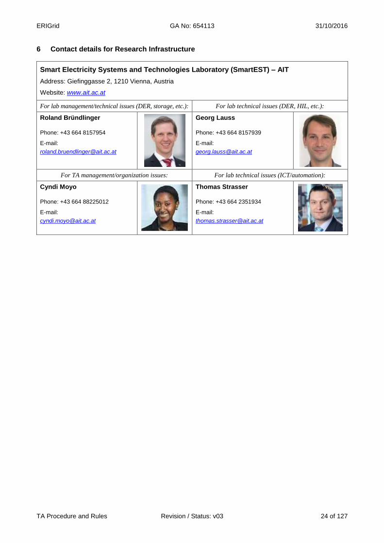
6 Contact details for Research Infrastructure
Smart Electricity Systems and Technologies Laboratory (SmartEST) – AIT
Address: Giefinggasse 2, 1210 Vienna, Austria
Website: www.ait.ac.at
For lab management/technical issues (DER, storage, etc.): For lab technical issues (DER, HIL, etc.):
Roland Bründlinger
Phone: +43 664 8157954
E-mail:
Georg Lauss
Phone: +43 664 8157939
E-mail:
For TA management/organization issues: For lab technical issues (ICT/automation):
Cyndi Moyo
Phone: +43 664 88225012
E-mail:
Thomas Strasser
Phone: +43 664 2351934
E-mail:

ERIGrid GA No: 654113 31/10/2016
TA Procedure and Rules Revision / Status: v03 25 of 127
COMMISSARIAT A L’ENERGIE ATOMIQUE ET AUX ENERGIES ALTERNATIVES
Institut National de l’Energie Solaire
1 Research Infrastructure
Name of Infrastructure/Installation PRISMES Hardware-in-the-loop simulator and multi microgrid test platform
Location CEA Ines, Le Bourget-du-Lac, France
Web Site www.ines-solaire.org
2 Description of the Research Infrastructure The heart of the infrastructure is the hardware in the loop (HIL) simulator which allows the simula-tion of any complex grid situation and which transforms a specific grid points into reality with the use of 45kVA three-phase power amplifier. This can be used to test specific components and the different control and management strategies. The hardware in the loop simulator is integrated in the multi microgrid platform PRISMES, which covers the complete campus of INES. Single phase and three phase grids are available at the platform, which are completely independent allowing running different projects in parallel.
Figure 7: CEA Ines (Le Bourget-du-Lac, France)
PRISMES consists of a low voltage (400V AC) micro-grid, including several generators with differ-ent technologies (renewable and conventional), controllable loads, electrical vehicles and storage systems. PRISMES can provide electricity to the main grid and is supervised by a SCADA system.
ERIGrid GA No: 654113 31/10/2016
TA Procedure and Rules Revision / Status: v03 26 of 127
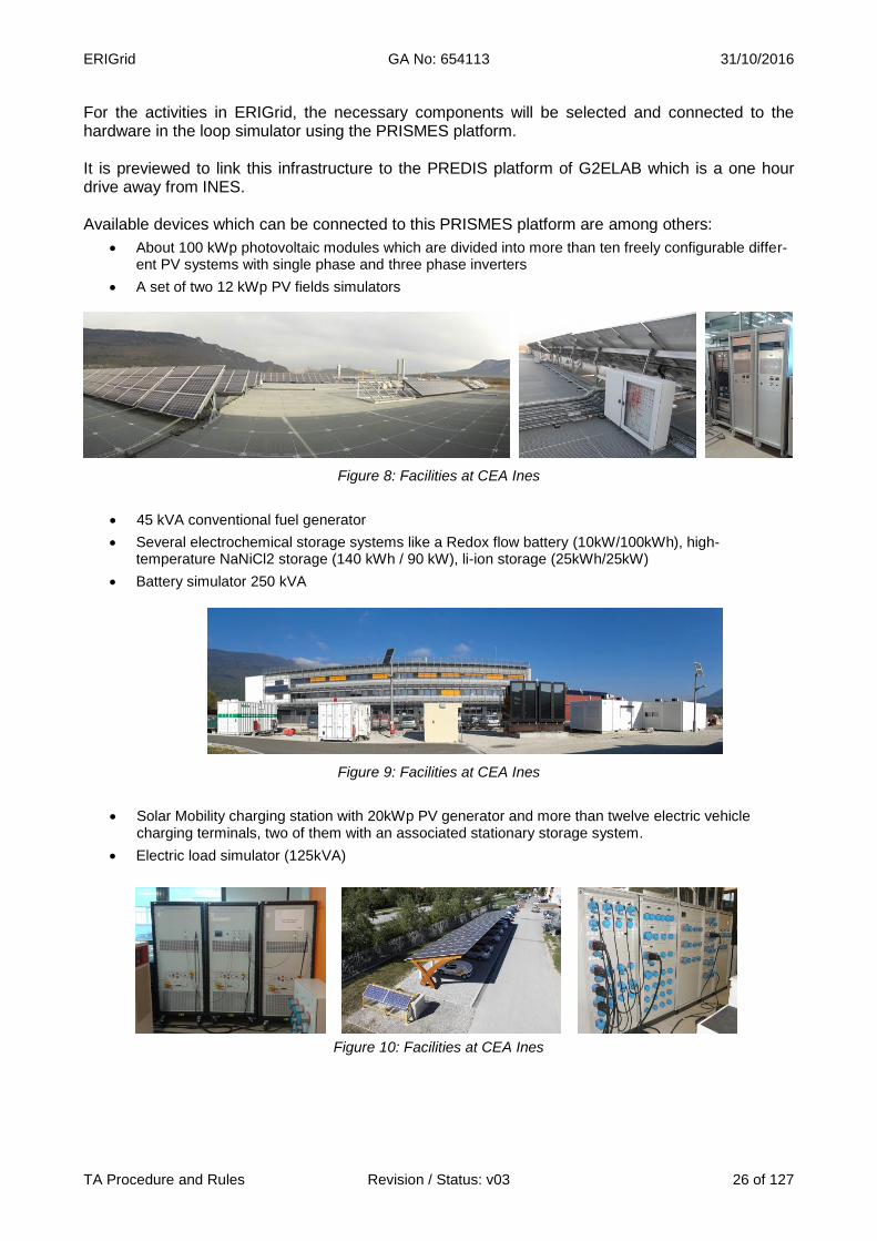
For the activities in ERIGrid, the necessary components will be selected and connected to the hardware in the loop simulator using the PRISMES platform. It is previewed to link this infrastructure to the PREDIS platform of G2ELAB which is a one hour drive away from INES. Available devices which can be connected to this PRISMES platform are among others:
About 100 kWp photovoltaic modules which are divided into more than ten freely configurable differ-ent PV systems with single phase and three phase inverters
A set of two 12 kWp PV fields simulators
Figure 8: Facilities at CEA Ines
45 kVA conventional fuel generator
Several electrochemical storage systems like a Redox flow battery (10kW/100kWh), high-temperature NaNiCl2 storage (140 kWh / 90 kW), li-ion storage (25kWh/25kW)
Battery simulator 250 kVA
Figure 9: Facilities at CEA Ines
Solar Mobility charging station with 20kWp PV generator and more than twelve electric vehicle charging terminals, two of them with an associated stationary storage system.
Electric load simulator (125kVA)
Figure 10: Facilities at CEA Ines

ERIGrid GA No: 654113 31/10/2016
TA Procedure and Rules Revision / Status: v03 27 of 127
3 Services offered by the Research Infrastructure The hardware in the loop simulator combined with the multi microgrid platform, provides a com-plete range of Rapid Control Prototyping (RCP) solutions to quickly develop, iterate and test control strategies for:
PV and storage power plant connected to grid
Storages (batteries, flywheel, etc.) connected to grid
Ancillary services (voltage control, frequency control, stability control …)
Microgrid operation, control and protection
This infrastructure was already accessible in the contest of the EU FP7 DERri and SOPHIA project program. Moreover, all user projects will be realized according to the procedures developed in NA5. 4 Brief description of the organization managing the Research Infrastructure INES is the reference center in France, and one of the first in Europe, dedicated to research, inno-vation and training on solar energy. Set up with the support of the Savoie Departmental Council and Rhône-Alpes Regional Council, it hosts teams from the CEA and the University of Savoie, and is supported by the CNRS and the CSTB. INES currently employs 400 staff, a figure that will rise to 500 engineers and scientists, on a 22,000-m² site equipped with state-of-the-art facilities. KEY FIGURES:
22,000-m² of laboratories, offices and training rooms
800 professionals trained each year
400 researchers and technicians
200 industrial partners
85 patents pending per year
15 laboratories
5 Transnational Access conditions offered by CEA-Ines All the offered experimental systems included in the PRISME platform are in the CEA-Ines centre in Le Bourget-du-lac, near Chambery, France. For safety reasons, for critical applications, the users are not expected to operate the systems by themselves; even when safety instructions will be provided, tests will be carried out by staff of CEA-Ines. For the rest of applications and after ad-hoc training, the user group will be granted access to the related facilities for the duration of the stay (with the support of CEA-Ines research-ers and laboratory technicians when necessary). The scheduling of the experiments will be agreed and booked prior to the stay according to the availability of the involved staff and equip-ment. Administrative documentation for the access (contract, non-disclosure agreement, etc.) will comply with ERIGrid common indications. In addition to the general corporate services (Internet connection, canteen, etc.) and the support and advice on accommodation and transportation to PRISMES infrastructure, the access being offered includes supervision and help of CEA-Ines staff:
As a complement to the pre-access contacts between the user group and CEA-Ines, the stay will start with an introductory meeting with a senior researcher for confirming the stay condi-tions (confidentiality, safety indications), scheduling the activities, explaining the on-site proce-dures, clarifying the logistics and technical details.
Preparatory work: a laboratory technician will assist the users for the installation of the devices, electrical connections, use of the specific instrumentation, preparation of a test procedure (if
ERIGrid GA No: 654113 31/10/2016
TA Procedure and Rules Revision / Status: v03 28 of 127
necessary) on the basis of the users requests, and programming of the experimental condi-tions.
CEA-Ines researchers will support the realisation and follow-up of the experiments.
CEA-Ines researchers will support the results interpretation, data processing and analysis, and test report preparation
Assurance covering the visiting period may be demanded by the local administrators.
In principle, a typical stay of 1 month is foreseen for a single user group but this period could be extended depending on the concrete user project. The user group can use the infrastructure for the defined time. Reimbursement of expenses: User expenses for the Transnational Access are paid by ERIGrid (EU H2020 Programme). This includes travels to PRISMES/CEA-Ines by plane, accommodation, daily subsistence, and daily transportation during the stay. For the user projects taking place in PRISMES, ERIGrid will refund the stay expenses when the stay is finished: the user must declare the incurred expenses and present the invoices/receipts to CEA-Ines in order to get the refund. Logical expenses must be made by the user: travels will be made in economy class and conven-tional hotels (not luxury) or equivalent accommodation will be used. As an indication (it is not a dai-ly allowance), a maximum subsistence fee of 160 €/person must be considered per day. Lunch will be provided at local canteen free to the user. 6 Contact details for Research Infrastructure
Institut National de l’Énergie Solaire, CEA INES
Address: Technopôle Savoie technolac, 50 Avenue du Lac Léman, 73370 Le Bourget-du-Lac
Website: www.ines-solaire.org
For Management/Organization Issues: For Technical issues:
Quoc Tuan TRAN Tel.: +33 4 79 79 22 31 E-mail: [email protected] Research Director Scientific Manager
Hervé Buttin Tel.: +33 (0)4-79-79-29-60
E-mail: [email protected] PRISMES zone Manager
Olivier WISS Tel.: +33 4 79 79 22 35 E-mail: [email protected] Experimental platform Manager
ERIGrid GA No: 654113 31/10/2016
TA Procedure and Rules Revision / Status: v03 29 of 127
Centre for Renewable Energy Sources and Saving (CRES)
1 Research Infrastructure
Name of Infrastructure/Installation Distributed Generation Laboratory (DG-Lab)
Location CRES - Pikermi, Attiki, Greece
Web Site www.cres.gr
2 Description of the Research Infrastructure The department of PVs and Distributed Generation of CRES is involved in applied research, mainly regarding power/energy balance issues at distribution system level. In the frame of the depart-ment’s research activities, there has been developed the Distributed Generation Laboratory, which consists of two main facilities: the Hybrid system/Microgrid test site and the PV systems laboratory. Each of the two facilities consists of the following laboratories: Experimental Microgrid: The Hybrid Power Plant and Microgrid laboratory is designed for studies
on the performance of stand‐alone and interconnected microgrids, but it can also serve as an emulator of autonomous weak grids, such as the power systems of islands. The microgrid’s backbone is a low voltage, 3‐phase network to which all DER components are connected. The interconnection of the cables allow, among others, the ad hoc introduction of lumped parameters such a resistors and inductances which emulate the characteristics of distribution lines. The system is designed with a capability of hosting devices up to 20kW. The communication and control of the system is primarily obtained via Interbus. Apart from that, the microgrid incorporates some extra acquisition and supervisory control components, such as a power quality meter for monitoring active/reactive power, voltage and frequency at the mains. The communication of this latter with the central control console is obtained via Modbus protocol. Futhermore, there is one set of battery inverters which makes use of proprietary RS485 protocol for data and commands exchange. The visualisation of supervision, monitoring and control of the microgrid is obtained by an application built in LabVIEW. The test site is appropriate for connecting DER units to evaluate their performance in a microgrid environment, but control components such as load controllers, energy management systems and distributed generation unit controllers can also be applied in order to implement demand side and energy management optimisation. Storage components are also available for use, including electrochemical (batteries) and chemical (Hydrogen) storage. The system is divided into three major layers: the power components, the control system and the communication interface.

ERIGrid GA No: 654113 31/10/2016
TA Procedure and Rules Revision / Status: v03 30 of 127
The power components of the microgrid include two PV panels (PV1 at 1.1 and PV2 at 4.4 kWp capacity) both of which are inteconnected via single-phase PV inverters (1.1 and 2.5kWp respectively). It is worth noting that PV2 is placed on a single-axis tracking system. In addition to the PVs the system is equipped with two battery banks, 400Ah/96V and 690Ah/60V respectively. Both banks utilise lead-acid batteries (OPzS). The energy conversion for the batteries is obtained via three single phase inverters which can be used in combination with one bank as a 3-phase system or as three separate single-phase systems. The battery inverters are capable of providing P/f and Q/V droop control while operating in grid-connected or islanded mode. In the latter case, which regards the operation of islanded power systems, a 3-phase diesel generator 400 Vac, 50 Hz, 12.5 kVA can be deployed for the electrification of the microgrid with extra power. Alternatively, the microgrid is (mainly) operated in interconnection to the LV distribution grid. The already existing system of generators is expandable by incorporating the equipment of the adjacent laboratory, namely the RES & Hydrogen Technologies Integration Laboratory, of CRES. Thus, in the DER portfolio there can be inculed a set of hydrogen technology units, namely a 5-kW PEM fuel cell and one electrolyser capable of producing 0.5Nm3/hr which functions as a load to the system. Apart from that, the other consumers of the microgrid are a 13 kW resistor load bank, one capacitive load (2.5kVAr) and one reverse osmosis desalination unit (3.5 kW).
Figure 11: Overview of microgrid’s main components of DG-Lab at CRES (Pikermi, Greece)
ERIGrid GA No: 654113 31/10/2016
TA Procedure and Rules Revision / Status: v03 31 of 127
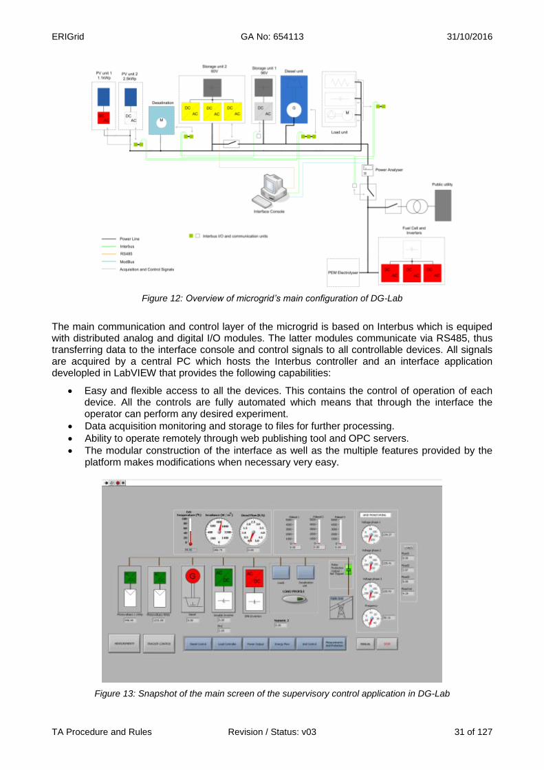
Figure 12: Overview of microgrid’s main configuration of DG-Lab
The main communication and control layer of the microgrid is based on Interbus which is equiped with distributed analog and digital I/O modules. The latter modules communicate via RS485, thus transferring data to the interface console and control signals to all controllable devices. All signals are acquired by a central PC which hosts the Interbus controller and an interface application developled in LabVIEW that provides the following capabilities:
Easy and flexible access to all the devices. This contains the control of operation of each device. All the controls are fully automated which means that through the interface the operator can perform any desired experiment.
Data acquisition monitoring and storage to files for further processing.
Ability to operate remotely through web publishing tool and OPC servers.
The modular construction of the interface as well as the multiple features provided by the platform makes modifications when necessary very easy.
Figure 13: Snapshot of the main screen of the supervisory control application in DG-Lab

ERIGrid GA No: 654113 31/10/2016
TA Procedure and Rules Revision / Status: v03 32 of 127
PV Systems Laboratory: It is divided into three laboratories each specialised on one type of com-ponents of a PV system, namely PV testing lab, Power Electronics lab and Battery testing lab.
The PV Testing laboratory is equipped with the following main hardware, intended for the
characterisation of PV cells, modules or arrays: o One class “A” solar simulator featuring a Xenon flash lamp and a computerised con-
trol and data acquisition system, for the acquisition of IV curve of PV cells/modules. o One field IV curve tracer for the outdoors IV curve acquisition of PV modules or ar-
rays for PV power up to 100kW. o One environmental chamber of useful volume of 5m3, with capability of temperature
control in the range from -40oC to 85oC, for the implementation of thermal cycling tests on PV modules.
o One long-term outdoor testing of PV modules.
Figure 14: Long-term test of PV modules in DG-Lab
The power electronics laboratory is concerned with the testing of inverters used in PV sys-tems, and evaluation of their suitability as DER equipment. The power electronics laborato-ry is equipped with the following hardware:
o One PV array simulator consisting of two programmable DC power sources reach-ing up to 400V and 25A.
o One load bank of 100 kVA total consumption. o One 12kVA programmable AC power source rated used in order to simulate a low
voltage power grid operation o One power-meter for the power measurement of DC and AC circuits as well as one
power quality meter for the measurement of electrical power quality of inverters, such as harmonics and transients.

ERIGrid GA No: 654113 31/10/2016
TA Procedure and Rules Revision / Status: v03 33 of 127
Figure 15: Programmable Grid simulator and load-bank control in DG-Lab
The battery testing laboratory focuses on the characterisation of batteries operating under specified conditions, referring to battery testing according to international standards (such as capacity or endurance tests) and the development of guidelines for the improvement of battery usage depending on the application. The main hardware of the lab is:
o A set of programmable charge/discharge power converters capable of performing tests according to programmed control parameters. These units range from low voltage and current up to 300 VDC and current capacities up to 300A.
o One high-rate discharge tester for 12V batteries testing with a maximum discharge current of 1500A.
o One environmental chamber providing temperature control between -20oC and +45oC during battery tests. The chamber’s volume is 1m3.
o One temperature controlled water bath for the immersion of batteries and control of their temperature during tests. The temperature range for control is between ambi-ent and 40oC.

ERIGrid GA No: 654113 31/10/2016
TA Procedure and Rules Revision / Status: v03 34 of 127
Figure 16: Battery testers in DG-Lab
3 Services offered by the Research Infrastructure
Figure 17: DG-Lab facilities
The services that the DG-Lab can provide with regard to all the above mentioned facilities are listed below:
Performance evaluation and characterisa-tion of distribution grid components, i.e. load controllers, inverters, control algorithms, power quality issues.
Investigation of microgrid operation scenari-os including islanded or grid-connected op-eration and Demand Side Management strategies, energy and cost optimisation studies.
Evaluation of control architectures, i.e. cen-tral, distributed, decentralised control schemes
Characterisation of PV cells, modules, pan-els etc. in terms of I-V curves and conform-ance with relevant standards
Characterisation of PV inverters perfor-mance in terms of efficiency and protection and conformance with relevant standards
Characterisation of battery cells and con-formance with relevant standards

ERIGrid GA No: 654113 31/10/2016
TA Procedure and Rules Revision / Status: v03 35 of 127
4 Brief description of the organization managing the Research Infrastructure The Centre for Renewable Energy Sources and Saving (CRES) is the Greek organization for Re-newable Energy Sources (RES), Rational Use of Energy (RUE) and Energy Saving (ES). CRES has been appointed as the national co-ordination centre in its area of activity. CRES was founded in September 1987 by Presidential Decree 375/87. It is a public entity, supervised by the Ministry of Environment and Energy and has financial and administrative independence. Its main goal is the research and promotion of RES/RUE/ES applications at a national and international level, as well as the support of related activities, taking into consideration the principles of sustainable develop-ment. The Centre is managed by a seven-member Administrative Council, which includes repre-sentatives from the General Secretariat of Research and Technology (Ministry of Education and Religious Affairs, Culture and Sports), the Public Power Corporation and the Hellenic Federation of Enterprises. CRES has a scientific staff of more than 120 highly qualified and experienced multi-disciplinary scientists and engineers. Its organisational structure comprises of the following units:
Division of Renewable Energy Sources
Division of Energy Efficiency
Division of Energy Policy and Planning
Division of Development Programmes
Division of Financial and Administrative Services Since 1992, CRES is located on its wholly owned premises in Pikermi, Attica, where in addition to over 2000 square meters of main office space, it has experimental outdoor installations, special-ised laboratories for energy technologies, a mechanical shop, conference rooms, a library and maintains a strong computing infrastructure. CRES has installed a demonstration Wind Park in the area of Agia Marina in Lavrio, Attica. The Wind Park is connected to the distribution network and has an installed capacity of 3MW. In the facility of the Wind Park, CRES operates the Park of EN-ergy Awareness (PENA), a new demonstration site for Renewable Energy Sources. In PENA eve-ryone has the opportunity to observe real small scale RES plants in operation, while the young visi-tors can learn about environmental friendly technologies through innovative educational tools. The Department of PVs and Distributed Generation of CRES is part of the Division of Renewable Energy Sources (RESD). RESD employs 40 scientists and engineers, focusing its activities on the design, support and execution of European and national RTD programs for the development of economically viable and environmentally friendly RES/RUE/ES technologies. The Department of PVs and DG cooperates systematically with organisations for the promotion of PV technology and Distributed Generation, such as EPIA and actively participates in European initiatives, e.g. the Electricity Networks of the Future (Smart Grids) and the European Technology Platforms for Pho-tovoltaics (PV–TRAC), etc. 5 Transnational Access conditions offered by CRES All the offered experimental systems included in the DG-Lab are in the same area, in nearby build-ings in Pikermi, near Athens, Greece.
For safety reasons, for critical applications, the users are not expected to operate the systems by themselves; even when safety instructions will be provided, tests will be carried out by staff of CRES. For the rest of applications and after ad-hoc training, the user group will have full access to the related facilities for the duration of the stay (with the support of CRES’s researchers and la-boratory technicians when necessary). The scheduling of the experiments will be agreed and booked prior to the stay according to the availability of the involved staff and equipment. Adminis-
ERIGrid GA No: 654113 31/10/2016
TA Procedure and Rules Revision / Status: v03 36 of 127
trative documentation for the access (contract, non-disclosure agreement, etc.) will comply with ERIGrid common indications.
In addition to the general corporate services (Internet connection etc.) and the support and advice on accommodation and transportation to CRES’s infrastructure, the access being offered includes supervision and help of CRES’s staff:
As a complement to the pre-access contacts between the user group and CRES, the stay will start with an introductory meeting with a senior researcher for confirming the stay conditions (confidentiality, safety indications), scheduling the activities, explaining the on-site procedures, clarifying the logistics and technical details.
Preparatory work: a laboratory technician will assist the users for the installation of the devices, electrical connections, use of the specific instrumentation, preparation of a test procedure (if necessary) on the basis of the users requests, and programming of the experimental condi-tions.
CRES’s researchers will support the realisation and follow-up of the experiments.
CRES’s researchers will support the results interpretation, data processing and analysis, and test report preparation
In principle, a typical stay of 2-3 weeks is foreseen for a single user group but this period could be extended depending on the concrete user project. The user group (typically 1-2 persons) can use the infrastructure for the defined time. Reimbursement of expenses: User expenses for the Transnational Access are paid by ERIGrid (EU H2020 Programme). This includes travels to DG-Lab (CRES) by plane, accommodation, daily subsistence, and daily trans-portation during the stay. For the user projects taking place in DG-Lab, CRES will refund the stay expenses when the stay is finished with two options:
By issuing an invoice to CRES with the sum total of the expenses if the home organisation temporarily covers the stay expenses of the visitor or
The visitor must declare the incurred expenses and present the invoices/receipts to CRES in order to get the refund.
Logical expenses must be made by the user: travels will be made in economy class and conven-tional hotels (not luxury) or equivalent accommodation will be used. As an indication (it is not a dai-ly allowance), a maximum subsistence fee of 150 €/person must be considered per day.
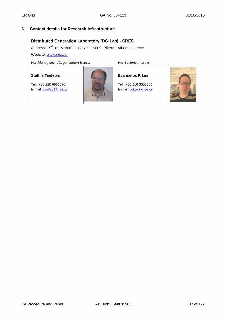
ERIGrid GA No: 654113 31/10/2016
TA Procedure and Rules Revision / Status: v03 37 of 127
6 Contact details for Research Infrastructure
Distributed Generation Laboratory (DG-Lab) - CRES
Address: 19th km Marathonos ave., 19009, Pikermi-Athens, Greece
Website: www.cres.gr
For Management/Organization Issues: For Technical issues:
Stathis Tselepis
Tel.: +30 210 6603370
E-mail: [email protected]
Evangelos Rikos
Tel.: +30 210 6603368
E-mail: [email protected]

ERIGrid GA No: 654113 31/10/2016
TA Procedure and Rules Revision / Status: v03 38 of 127
DNV∙GL
Strategic Research & Innovation
1 Research Infrastructure
Name of Infrastructure/Installation Flex Power Grid Laboratory (FPGL)
Location DNV∙GL – Arnhem, the Netherlands
Web Site www.FlexPowerGridLab.com
2 Description of the Research Infrastructure The Flex Power Grid Lab (FPGL) in Arnhem, the Netherlands takes a unique position in the world because of its voltage capability (24kV,3Φ;50kV,1Φ), power range (1MVA) and bandwidth (2.4kHz). It builds on its long term experience of component research and testing in order to set the standard for future system validation research and testing.
Figure 18: FPGL at DNV GL (Arnhem, the Netherlands)
ERIGrid GA No: 654113 31/10/2016
TA Procedure and Rules Revision / Status: v03 39 of 127
The Flex Power Grid Laboratory infrastructure is particularly well suited for research on, or testing of utility-interactive devices intended for low-voltage or medium-voltage distribution grids, such as power electronics converters, combined-heat & power (CHP) systems and storage systems. It fea-tures freely programmable, high-power AC and DC sources capable of realistically emulating a grid connection, a PV system, a storage system or a combination thereof. This enables extensive re-search and testing capabilities on aspects such as grid compliance – including fault-ride-through (FRT), interface protection and power quality (PQ) – functionality, component performance and component reliability. Furthermore, the infrastructure incorporates real-time simulation capabilities to extend the research
capabilities into the domain of Power Cybernetics6 as part of power system validation.
A fully equipped measuring system is provided in the safety of the command-room. Moreover, the command room overlooks the laboratory floor on which the research objects are clearly visible but guarantees the user’s safety at all times. One particular feature of this infrastructure that deserves special attention is its ability to influence the power quality of the AC distribution grid within the facility (AC grid simulator) to which the re-search equipment can be connected. It is possible to superimpose an arbitrary contribution of har-monic voltages on the grid voltage to simulate a badly polluted grid, or a badly polluted load (in re-verse power flow direction). Dynamic network phenomena such as voltage and frequency varia-tions can be realized with the ability to include voltage dips, phase jumps and rapid voltage chang-es, see Figure 19: . The AC grid simulator is also capable of coping with unbalanced loads/sources and still provides the capability to superimpose harmonic voltages and instigate dynamic network phenomena for the purpose of interaction verification (equipment with grid under dynamic condi-tions) as well as component immunity and susceptibility analysis.
6 Reference: DNV∙GL’s position paper on Power Cybernetics – The future of validation; 2016 (available on request).
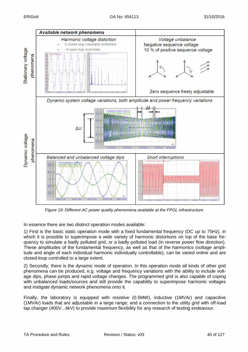
ERIGrid GA No: 654113 31/10/2016
TA Procedure and Rules Revision / Status: v03 40 of 127
Figure 19: Different AC power quality phenomena available at the FPGL infrastructure
In essence there are two distinct operation modes available:
1) First is the basic static operation mode with a fixed fundamental frequency (DC up to 75Hz), in which it is possible to superimpose a wide variety of harmonic distortions on top of the base fre-quency to simulate a badly polluted grid, or a badly polluted load (in reverse power flow direction). These amplitudes of the fundamental frequency, as well as that of the harmonics (voltage ampli-tude and angle of each individual harmonic individually controllable), can be varied online and are closed-loop controlled to a large extent.
2) Secondly, there is the dynamic mode of operation. In this operation mode all kinds of other grid phenomena can be produced, e.g. voltage and frequency variations with the ability to include volt-age dips, phase jumps and rapid voltage changes. The programmed grid is also capable of coping with unbalanced loads/sources and still provide the capability to superimpose harmonic voltages and instigate dynamic network phenomena onto it. Finally, the laboratory is equipped with resistive (0.5MW), inductive (1MVAr) and capacitive (1MVAr) loads that are adjustable in a large range; and a connection to the utility grid with off-load tap changer (400V...4kV) to provide maximum flexibility for any research of testing endeavour.
ERIGrid GA No: 654113 31/10/2016
TA Procedure and Rules Revision / Status: v03 41 of 127
3 Services offered by the Research Infrastructure
The facility allows researchers to gain “hands-on” experience on the interaction of utility-interactive equipment, such as power electronics converters and its controls, with a distribution system and thereby fosters practical innovation in equipment technology within the power system industry.
Within the scope of the ERIGrid – Trans National Access activities, the FPGL research infrastruc-ture offers the following services (for inspirational purposes, actual services can differ):
Analysis, measurement and testing of (large scale) utility-interactive, power electronics equipment (inverters, battery storage systems, UPS systems, Vehicle2Grid and EV charging applications, active (harmonic) filters, STATCOMs, etc.) behaviour, in the development and de-ployment of advanced inverter functions, ancillary services, synthetic inertia, grid stabil-ity, etc.
Development, optimization, measurement and testing of (large-scale) smart grid operation and control algorithms based on distributed embedded control in power electronics equip-ment, for example.
Individual conformance testing of utility-interactive power electronics equipment and evaluation of the performance of devices within a distribution system under different static and dynamic electrical conditions (efficiency, power quality (see Figure 19: Fehler! Verweis-
quelle konnte nicht gefunden werden.), etc.), also as (part of) grid compliance initiatives7.
Analysis of system stability (large and small signal) in grids with a high penetration of power electronics equipment and/or controllers.
Model validation of utility-interactive equipment and/or controllers within distribution grid appli-cations.
4 Brief description of the organization managing the Research Infrastructure DNV GL Driven by its purpose of safeguarding life, property and the environment, DNV GL enables organi-sations to advance the safety and sustainability of their business. DNV GL provides classification and technical assurance along with software and independent expert advisory services to the mari-time, oil & gas and energy industries. We also provide certification services to customers across a wide range of industries. Combining leading technical and operational expertise, risk methodology and in-depth industry knowledge, DNV GL empowers its customers’ decisions and actions with trust and confidence. The company continuously invests in research and collaborative innovation to provide customers and society with operational and technological foresight. DNV GL, whose ori-gins go back to 1864, operates globally in more than 100 countries with its 16,000 professionals dedicated to helping their customers make the world safer, smarter and greener. In the Energy industry DNV GL delivers world-renowned testing and advisory services to the energy value chain including renewables and energy efficiency. Our expertise spans onshore and offshore wind power, solar, conventional generation, transmission and distribution, smart grids, and sustainable energy use, as well as energy markets and regulations. Our 3,000 energy experts support clients around the globe in delivering a safe, reliable, efficient, and sustainable energy supply. DNV GL Strategic Research & Innovation The objective of strategic research is through new knowledge and services to enable long term in-novation and business growth in support of the overall strategy of DNV GL. Such research is car-
7 Although DNVGL is accredited for performing grid compliance certification to a number of (inter)national standards, no certif ication is
available within ERIGrid TNA activities.

ERIGrid GA No: 654113 31/10/2016
TA Procedure and Rules Revision / Status: v03 42 of 127
ried out in selected areas that are believed to be of particular significance for DNV GL in the future. 5 Transnational Access conditions offered by DNV∙GL All ERIGrid trans-national access activities are performed in a professional environment with highly qualified personnel, available for scientific discussions on the preparation and proceedings of the research and test activities. DNV∙GL's experience with commercial testing allows users to benefit from DNV∙GL's knowledge about the latest industry requirements on testing. The commercial la-boratory environment provides all the required logistical support for the preparation and execution of the mutually agreed upon experiments. The research infrastructure will only be used accordance with a mutually agreed test plan, which is based on the agreed ERIGrid user project. Furthermore, as the facility is a medium-voltage, high-power facility, local legislation as well as company policy dictate that the research infrastructure be operated by qualified DNV∙GL personal only. DNVGL staff will be available to assist in any prepar-atory activities (preparation of test circuit, measurement set up, etc.), measurement data and result interpretation (if applicable) and other project related aspects on-site. The safety of all those present at the research facility is our top concern. Safety instructions will therefore be provided for all visitors on arrival. All visitors will need to wear appropriate protective gear (safety shoes and safety hats, for example) during all activities at the research facility, which they are expected to provide themselves. This with the exception of safety hats, which are availa-ble at the research facility itself. The access to the laboratory infrastructure will be mutually agreed upon and booked prior to the stay, according to the availability of the required DNV∙GL staff and equipment. All the administra-tion required for the access (contract, non-disclosure agreement, etc.) will comply with the both the DNV∙GL terms and conditions for the execution of projects in its laboratories as well as the com-monly agreed ERIGrid terms and conditions. The duration of stay at the research infrastructure is typically 1 week for a single user group, but this period can be extended depending on the terms and conditions of the agreed user project. The user group (typically 2 persons) can use the infrastructure for the agreed time as per the ap-proved user project. Reimbursement of expenses: User expenses for the Transnational Access are paid by ERIGrid (EU H2020 Programme). This includes travels to FPGL (DNV∙GL) by public transport (plane, train, bus, metro, etc.), accommoda-tion, daily subsistence, and daily transportation during the stay. For the user projects taking place in FPGL, DNV∙GL will refund the expenses incurred during the stay after the stay has finished: the user must declare the incurred expenses and present the as-sociated invoices/receipts to DNV∙GL within 1 month after the stay has finished, in order to get the cost reimbursed. Logistical expenses must be made by the user: air and rail travel will be made in economy/second class and conventional hotels (not luxury) or equivalent accommodation will be used. As an indica-tion (it is not a daily allowance), a maximum subsistence fee of 160 €/person must be considered per day. Lunch will be provided at DNV∙GL’s canteen at no cost to the user.

ERIGrid GA No: 654113 31/10/2016
TA Procedure and Rules Revision / Status: v03 43 of 127
6 Contact details for Research Infrastructure
Flex Power Grid Laboratory (FPGL) - DNV∙GL
Address: Business Park Arnhems Buiten, Building R11, Utrechtseweg 310, 6812AR Arnhem, the Netherlands
Website: www.dnvgl.com/energy
Erik de Jong
Tel.: +31 26 356 2794
E-mail: [email protected]
ERIGrid GA No: 654113 31/10/2016
TA Procedure and Rules Revision / Status: v03 44 of 127
Technical University of Denmark
1 Research Infrastructure
Name of Infrastructure/Installation SYSLAB and ICL
Location Technical University of Denmark, Kgs. Lyngby, Denmark
Web Site www.dtu.dk
http://www.powerlab.dk/
2 Description of the Research Infrastructure 2.1 SYSLAB SYSLAB is an experimental facility at DTU Risø campus, designed as a testbed for advanced con-trol and communication concepts for power grids. The facility has been extended several times since its inception in 2005; the current setup extends across multiple sites on Risø campus within an area of about one square kilometer. A 400V, 3-phase grid with a total of 16 busbars and 119 automated coupling points serves as the electrical backbone of the facility and allows a large varie-ty of different grid topologies to be set up by means of a central crossbar switch. When all cables are in use, a maximum feeder length of up to 3km can be achieved. The grid can be connected to the campus distribution grid through one of several interconnection points, operated in island mode or be split up into multiple independent subgrids.

ERIGrid GA No: 654113 31/10/2016
TA Procedure and Rules Revision / Status: v03 45 of 127
Figure 20: Layout of the electrical grid in SYSLAB
Figure 21: Overview of the SYSLAB facility on Risø campus

ERIGrid GA No: 654113 31/10/2016
TA Procedure and Rules Revision / Status: v03 46 of 127
A large variety of DER units can be connected at different points of the grid. These include two wind turbines, three PV installations, a conventional (combustion engine) generator, three buildings with controllable heating, vanadium redox-flow and lithium-ion batteries for storage, electric vehicle charging posts and various other types of controllable loads. Unit sizes range between 10 and 100 kVA. A back-to-back converter allows controlled power exchange between SYSLAB and the cam-pus grid and can be used for equipment simulation or PHIL tests. All equipment on the grid is automated and remote-controllable. Each unit is supervised locally by a dedicated computing node which acts as a communication gateway. The node computers run a custom, Java-based software platform on top of a standard Linux installation which provides com-munication between nodes, facilitates the deployment of local controllers and logs unit data. The nodes are almost identical, and the layout of the communication network does not put any of them at the center of the network. This results in great flexibility with respect to control architectures; standard master-slave control concepts can be tested as well as less traditional approaches such as controllers based on peer-to-peer communication or multi-layered hybrid control systems. Various software interfaces exist for the interaction with the laboratory infrastructure; besides the native Java API many SCADA functions can be accessed through Matlab. Integration with most other programming languages such as C or Python is possible via the web services and XMLRPC APIs. SYSLAB is currently being expanded with a small district heating network in order to study the interaction between energy carriers. A custom-built “heat substation” allows the flexible intercon-nection and transfer of energy between a number of heat sources, heat consumers and a storage tank. In the current setup, a heat pump and an electrical booster heater allow energy to be trans-ferred from the electrical network of SYSLAB to the heat network. The Flexhouses are three highly automated buildings which are integrated into SYSLAB. Flexhouse I is a former office pavilion, while Flexhouses II and III were originally built as single-family homes before being retrofitted for research use. Their primary purpose is to facilitate re-search on the integration of buildings into the control of energy systems. Flexhouse I is electrically heated and cooled, with individual electrical radiators and split airconditioning systems in each room. The other two buildings have water-borne central heating systems which are fed from the SYSLAB district heating switchboard. All buildings are equipped with a multitude of sensors, including room temperature, light intensity, presence/motion, window and door contacts. Each building has a variety of controllable energy consumers - appliances, space heating and cooling and hot tap water. A custom-made building automation platform allows the deployment of building controllers written in Java or Python which are able to interact with the building as well as process remote-control signals from SYSLAB, e.g. for demand response applications. 2.2 ICL The Intelligent Control Lab (ICL) is a laboratory for research, development and test of new ad-vanced principles for intelligent supervision and control of smart grids. It consists of:
A full-scale ABB Network Manager SCADA system which is linked to the SCADA system operated by the local DSO on the island of Bornholm and allows monitoring of the entire Bornholm grid on a large monitor wall in a realistic control room setup
A 10-rack real-time digital simulator (RTDS) able to simulate power systems of up to 480 buses. The RTDS can be used for Hardware-in-the-Loop (HIL) tests and can be connected to a linear high power amplifier in order to conduct Power Hardware-in-the-loop (PHIL) ex-periments.

ERIGrid GA No: 654113 31/10/2016
TA Procedure and Rules Revision / Status: v03 47 of 127
A PMU extension to the RTDS with GTNET PMU cards (46 channels) for research and de-velopment on wide area monitoring and control.
A PMU lab with a PMU test platform, consisting of a Doble amplifier and PMUs from sever-al manufacturers.
An IBM Blade Center for hosting and executing optimization and control software. Potential applications of the ICL include proof-of-concept tests of intelligent control and operator training, HIL and PHIL testing, wide area monitoring and control topics, relay testing and protection coordination using IEC 61850 and PMU testing according to IEEE C37.118.1.
3 Services offered by the Research Infrastructure SYSLAB has been used in the past for a variety of applications, including:
Development and proof-of-concept testing of novel control concepts for smart grids
Component characterization and testing
Validation of simulation tools
Electrical vehicle interoperability testing
Testing of real-time prediction algorithms
Development of demand response algorithms
Testing of communication performance at the protocol level
Proof-of-concept testing of data models for smart grid communication
Island grid and microgrid studies
Potential applications of the ICL include:
Proof-of-concept tests of intelligent control algorithms
Operator training
HIL and PHIL testing against the RTDS
Wide area monitoring and control related research
Relay testing and protection coordination using IEC 61850
PMU testing according to IEEE C37.118.1.
4 Brief description of the organization managing the Research Infrastructure The Center for Electric Power and Energy (CEE) is a center for research, innovation and education at the Technical University of Denmark (DTU), department of Electrical Engineering. CEE covers a broad range of electric technologies including production, transmission, distribution and consump-tion of electricity as well the interactions with other energy carrier systems such as district heating. CEE aims at enabling a more intelligent, flexible and automated electric power system that can ac-commodate the future expansion of renewable energy production and the long term vision of a fos-sil-free society. CEE holds competences within electric components, electric power systems, au-tomation of complex power systems, electricity markets, end-user interaction and intelligent energy systems. The Energy Systems Operation and Management (ESOM) group is a research group within CEE and performs research covering the development and analysis of new solutions for the manage-ment and operation of future distributed power systems with a high share of renewable energy and distributed energy resources. The investigation of future system architectures, centralized as well as decentralized, is part of the research area, with the goal to provide optimal and seamless inter-action of all system elements and subsystems. This includes e.g. agent-based solutions and ag-gregation. The solutions cover novel ICT implementations combined with innovative market-based designs and new grid management methods and important aspect is interoperability of communi-

ERIGrid GA No: 654113 31/10/2016
TA Procedure and Rules Revision / Status: v03 48 of 127
cation and services. ESOM research efforts also cover innovative monitoring, operation and control which enable for example management of grid bottleneck, islanding solutions and microgrids. The research has important interfaces with many of the other groups including research within markets and energy resources, services and control. PowerLabDK is an experimental platform for electric power and energy laboratory administered by CEE. PowerLabDK supports development, test, training and demonstration of technologies that will contribute to the development of a reliable, cost efficient and sustainable energy system based on renewable energy sources. PowerLabDK is a national GreenLab under the Danish Energy Agency. The facilities contain flexible test laboratories, large-scale experimental facilities and a complete full-scale power distribution system on the Island of Bornholm which serves as a data source and platform for full-scale and real-life experiments. The PowerLabDK facilities welcome engineers and researchers from industry and academia as well as innovative students. The two PowerLabDK fa-cilities available for the Transnational Access programme in ERIGrid are SYSLAB and the Intelli-gent Control Lab.
5 Transnational Access conditions offered by DTU The offered experimental facilities are located in Denmark, SYSLAB in Roskilde, DTU Risø Cam-pus and Intelligent Control Lab in Kgs. Lyngby, DTU Lyngby Campus.
For safety reasons, for critical applications, the users are not expected to operate the systems by themselves; even when safety instructions will be provided, tests will be carried out by staff of DTU. For the rest of applications and after ad-hoc training, the user group will have full access to the related facilities for the duration of the stay (with the support of DTU’s researchers and labora-tory technicians when necessary). The scheduling of the experiments will be agreed and booked prior to the stay according to the availability of the involved staff and equipment. Administrative documentation for the access (contract, non-disclosure agreement, etc.) will comply with ERIGrid common indications.
In addition to the general corporate services (Internet connection, canteen, etc.) and the support and advice on accommodation and transportation to DTU’s infrastructure, the access being offered includes supervision and help of DTU’s staff:
● As a complement to the pre-access contacts between the user group and DTU, the stay will start with an introductory meeting with a senior researcher for confirming the stay conditions (confidentiality, safety indications), scheduling the activities, explaining the on-site procedures, clarifying the logistics and technical details.
● Preparatory work: a laboratory technician install the devices, electrical connections, use of the specific instrumentation, preparation of a test procedure (if necessary) on the basis of the users requests, and configuration of the experimental conditions.
● DTU’s researchers will support the realisation and follow-up of the experiments.
● DTU’s researchers will support the results interpretation, data processing and analysis, and test report preparation
In principle, a typical stay of 2 weeks is foreseen for a single user group but this period could be extended depending on the concrete user project. The user group (usually 2 persons) can use the infrastructure for the defined time.
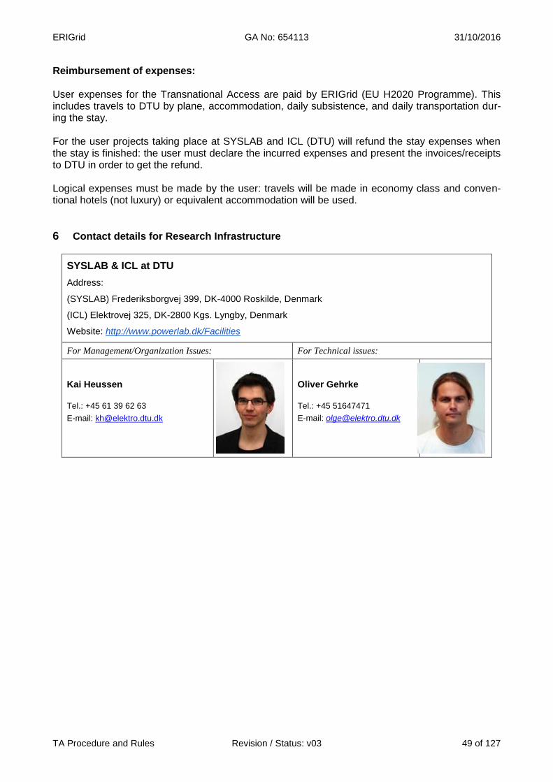
ERIGrid GA No: 654113 31/10/2016
TA Procedure and Rules Revision / Status: v03 49 of 127
Reimbursement of expenses: User expenses for the Transnational Access are paid by ERIGrid (EU H2020 Programme). This includes travels to DTU by plane, accommodation, daily subsistence, and daily transportation dur-ing the stay. For the user projects taking place at SYSLAB and ICL (DTU) will refund the stay expenses when the stay is finished: the user must declare the incurred expenses and present the invoices/receipts to DTU in order to get the refund. Logical expenses must be made by the user: travels will be made in economy class and conven-tional hotels (not luxury) or equivalent accommodation will be used.
6 Contact details for Research Infrastructure
SYSLAB & ICL at DTU
Address:
(SYSLAB) Frederiksborgvej 399, DK-4000 Roskilde, Denmark
(ICL) Elektrovej 325, DK-2800 Kgs. Lyngby, Denmark
Website: http://www.powerlab.dk/Facilities
For Management/Organization Issues: For Technical issues:
Kai Heussen
Tel.: +45 61 39 62 63
E-mail: [email protected]
Oliver Gehrke
Tel.: +45 51647471
E-mail: [email protected]
ERIGrid GA No: 654113 31/10/2016
TA Procedure and Rules Revision / Status: v03 50 of 127
Laboratoire de Génie Électrique de Grenoble
1 Research Infrastructure
Name of Infrastructure/Installation PREDIS Real-Time PHIL simulation platform
Location G2Elab, Grenoble, France
Web Site www.g2elab.grenoble-inp.fr
2 Description of the Research Infrastructure The G2ELab (i.e., GRENOBLE INP) owns two real-time (RT) multiprocessors digital simulators, in the framework of the PREDIS centre. They are a new generation of RT simulators, allowing appli-cations from different physical domains like aerial or surface transports, fluids, mechanical and electrical systems using Matlab-Simulink® environment. Such simulators are able to carry out Hardware-In-the-Loop (HIL) as well as Power-Hardware-In-the-Loop (PHIL) applications. In such simulations, a part of the simulated system is achieved numerically in the heart of the simulator, whereas the other part is integrated in the open (or closed) loop through power amplifiers, in the form of physical components (or emulated numerically by calculators). The different components and the heart of the simulator can be linked by the communication system, which uses different communication protocols (TCP/IP, Ethernet, FireWire, Infiniband, etc.). It allows the remote opera-tion of real-time systems via local networks or Internet. Moreover, a RT smart grid demonstrator is under development in the framework of a national research project. It will include a digital simula-tion of a distribution grid (MV/LV), some programmable loads and programmable sources to emu-late this equipment, smart meters, amplifiers, a SCADA system (Supervisory Control And Data Ac-quisition) including optimal energy management ADA functions, and a communication network us-ing IEC 61850.
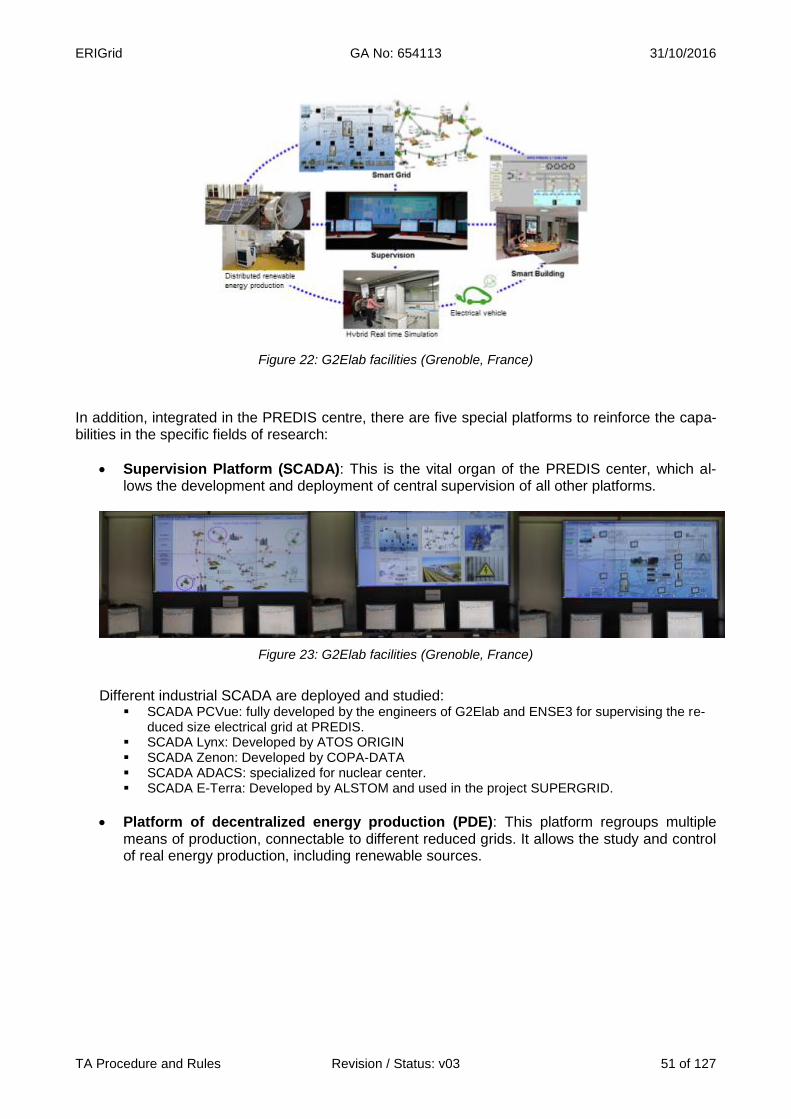
ERIGrid GA No: 654113 31/10/2016
TA Procedure and Rules Revision / Status: v03 51 of 127
Figure 22: G2Elab facilities (Grenoble, France)
In addition, integrated in the PREDIS centre, there are five special platforms to reinforce the capa-bilities in the specific fields of research:
Supervision Platform (SCADA): This is the vital organ of the PREDIS center, which al-lows the development and deployment of central supervision of all other platforms.
Figure 23: G2Elab facilities (Grenoble, France)
Different industrial SCADA are deployed and studied:
SCADA PCVue: fully developed by the engineers of G2Elab and ENSE3 for supervising the re-duced size electrical grid at PREDIS.
SCADA Lynx: Developed by ATOS ORIGIN SCADA Zenon: Developed by COPA-DATA SCADA ADACS: specialized for nuclear center. SCADA E-Terra: Developed by ALSTOM and used in the project SUPERGRID.
Platform of decentralized energy production (PDE): This platform regroups multiple means of production, connectable to different reduced grids. It allows the study and control of real energy production, including renewable sources.

ERIGrid GA No: 654113 31/10/2016
TA Procedure and Rules Revision / Status: v03 52 of 127
Figure 24: G2Elab facilities (Grenoble, France)
Platform of reconfigurable electrical grid: This platform regroups several real instru-mented and flexible electrical grids with a reduced size of 30kVA. It allows the study on dif-ferent structure of future smart grid. The reconfigurable distribution and industrial grids use the production means and loads of PDE platform and is supervised by the SCADA platform.
Figure 25: G2Elab facilities (Grenoble, France)
Platform of real time simulation and PHIL: This platform offers the tools for electrical sys-tem design, optimization and control. It allows users to actualize researches on all kind of emulated grids with interaction with real components. This modular platform is suitable for different research thematic, from electrical vehicle to renewable energy resources.
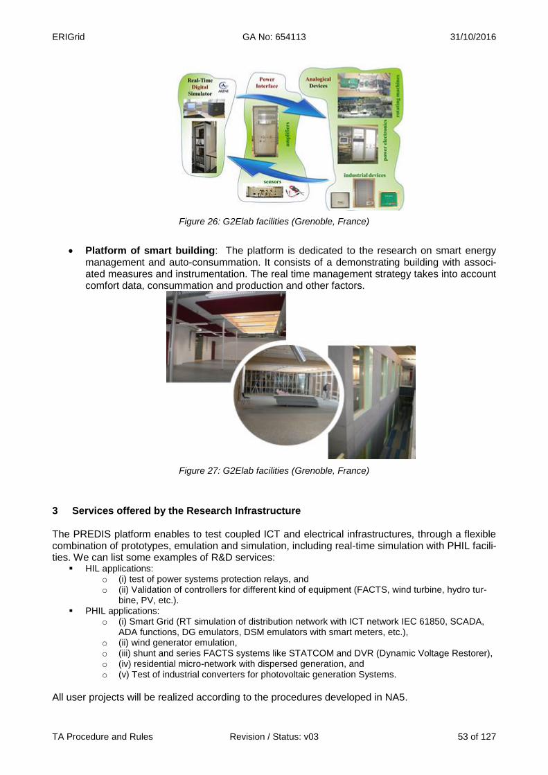
ERIGrid GA No: 654113 31/10/2016
TA Procedure and Rules Revision / Status: v03 53 of 127
Figure 26: G2Elab facilities (Grenoble, France)
Platform of smart building: The platform is dedicated to the research on smart energy management and auto-consummation. It consists of a demonstrating building with associ-ated measures and instrumentation. The real time management strategy takes into account comfort data, consummation and production and other factors.
Figure 27: G2Elab facilities (Grenoble, France)
3 Services offered by the Research Infrastructure The PREDIS platform enables to test coupled ICT and electrical infrastructures, through a flexible combination of prototypes, emulation and simulation, including real-time simulation with PHIL facili-ties. We can list some examples of R&D services:
HIL applications: o (i) test of power systems protection relays, and o (ii) Validation of controllers for different kind of equipment (FACTS, wind turbine, hydro tur-
bine, PV, etc.). PHIL applications:
o (i) Smart Grid (RT simulation of distribution network with ICT network IEC 61850, SCADA, ADA functions, DG emulators, DSM emulators with smart meters, etc.),
o (ii) wind generator emulation, o (iii) shunt and series FACTS systems like STATCOM and DVR (Dynamic Voltage Restorer), o (iv) residential micro-network with dispersed generation, and o (v) Test of industrial converters for photovoltaic generation Systems.
All user projects will be realized according to the procedures developed in NA5.
ERIGrid GA No: 654113 31/10/2016
TA Procedure and Rules Revision / Status: v03 54 of 127
4 Brief description of the organization managing the Research Infrastructure Ideally located in the heart of the French Alps, Grenoble Institute of Technology is one of Europe's leading technology universities. It offers a range of engineering, masters and doctoral courses both in French and in English, driven by world-class research in 38 laboratories, and 6 technology plat-forms, developed in partnership with other institutions. Grenoble Institute of Technology's mission is to empower new generations of engineers to respond to global challenges in the fields of energy, the digital world, micro- and nanotechnologies, the en-vironment, as industries of the future. For 120 years, Grenoble Institute of Technology has been instrumental in developing innovative solutions with industrial partners to support continuous tech-nological advances and economic growth. With its solid combination of teaching, research and business promotion, Grenoble Institute of Technology plays a key role in making Grenoble one of the most attractive scientific and industrial locations worldwide. International cooperation has always been a priority for Grenoble Institute of Technology, develop-ing programs alongside renowned technology universities in Europe, North and South America and Asia. The Institute is proud to host research and teaching fellows and students from right across the world, and to encourage its students and staff to travel abroad to work in partner universities or do internships in foreign companies. 5 Transnational Access conditions offered by G2Elab/Grenoble-INP All the offered experimental systems included in the PREDIS centre are in the Green-ER building in Grenoble, France. Access to PREDIS centre is granted under agreed authorization of both G2Elab and Greno-ble-INP.
For safety reasons, for critical applications, the users are not expected to operate the systems by themselves; even when safety instructions will be provided, tests will be carried out by staff of G2Elab. For the rest of applications and after ad-hoc training, the user group will be granted ac-cess to the related facilities for the duration of the stay (with the support of G2Elab researchers and laboratory technicians when necessary). The scheduling of the experiments will be agreed and booked prior to the stay according to the availability of the involved staff and equipment. Adminis-trative documentation for the access (contract, non-disclosure agreement, etc.) will comply with ERIGrid common indications.
In addition to the general corporate services (Internet connection, canteen, etc.) and the support and advice on accommodation and transportation to G2ELab infrastructure, the access being of-fered includes supervision and help of G2Elab staff:
As a complement to the pre-access contacts between the user group and G2Elab, the stay will start with an introductory meeting with a senior researcher for confirming the stay conditions (confidentiality, safety indications), scheduling the activities, explaining the on-site procedures, clarifying the logistics and technical details.
Preparatory work: a laboratory technician will assist the users for the installation of the devices, electrical connections, use of the specific instrumentation, preparation of a test procedure (if necessary) on the basis of the users requests, and programming of the experimental condi-tions.

ERIGrid GA No: 654113 31/10/2016
TA Procedure and Rules Revision / Status: v03 55 of 127
The preparatory works (before granting access and in the process) are counted towards the units of access. G2Elab researchers will support the realisation and follow-up of the experi-ments.
G2Elab researchers will support the results interpretation, data processing and analysis, and test report preparation
Assurance covering the visiting period may be demanded by the local administrators.
In principle, a typical stay of 1 month is foreseen for a single user group but this period could be extended depending on the concrete user project. The user group can use the infrastructure for the defined time. The user group will have access to an office, computer and telephone. Reimbursement of expenses: User expenses for the Transnational Access are paid by ERIGrid (EU H2020 Programme). This includes travels to PREDIS-G2Elab by plane, accommodation, daily subsistence, and daily trans-portation during the stay. For the user projects taking place in PREDIS, ERIGrid will refund the stay expenses when the stay is finished: the user must declare the incurred expenses and present the invoices/receipts to G2Elab in order to get the refund. Logical expenses must be made by the user: travels will be made in economy class and conven-tional hotels (not luxury) or equivalent accommodation will be used. As an indication (it is not a dai-ly allowance), a maximum subsistence fee of 160 €/person must be considered per day. Lunch will be provided at local canteen free to the user. 6 Contact details for Research Infrastructure
Laboratoire de Génie Electrique de Grenoble, G2Elab
Address: 21 avenue de Martyrs, 38031 Grenoble CEDEX, France
Website: www.g2elab.grenoble-inp.fr
For Management/Organization Issues: For Technical issues:
Yvon Besanger
Tel.: +33 4 76 82 64 41
E-mail: [email protected]
Van Hoa Nguyen
Tel.: +33 4 76 82 71 87
E-mail:

ERIGrid GA No: 654113 31/10/2016
TA Procedure and Rules Revision / Status: v03 56 of 127
ICCS-NTUA
1 Research Infrastructure
Name of Infrastructure/Installation ICCS – NTUA – EESL (ELECTRIC ENERGY SYSTEMS LABORATORY)
Location 9, Iroon Polytechniou Str., 157 73 Zografou Campus, Athens, Greece
Web Site www.iccs.gr/en
www.smartrue.gr
2 Description of the Research Infrastructure The EESL (ELECTRIC ENERGY SYSTEMS LABORATORY) comprises the following equipment:
Low Voltage Microgrid: A main component of the laboratory is the single phase microgrid that includes a PV generator, a small Wind Turbine, battery energy storage, controllable loads and a controlled interconnection to the local LV grid. The battery unit, the PV genera-tor and the Wind Turbine are connected to the AC grid via fast-acting DC/AC power con-verters. The converters are suitably controlled to permit the operation of the system either interconnected to the LV network (grid-tied), or in stand-alone (island) mode, with a seam-less transfer from the one mode to the other. Part of the laboratory’s infrastructure is the 3-phase microgrid with main elements 3 single-phase battery inverters and micro-sources connected in each phase.
Multi-Microgrids Cluster: The three ICCS-NTUA Microgrids form a Multi-Microgrid cluster (through Electrical and Internet connection) in order to investigate the development and verification of different control strategies and the impact of wide deployment of Microgrids at the distribution level.
Multi-Agent System for Microgrid Operation: Multi-agent technology has been imple-mented for the control of the distributed sources and the loads of the LV microgrid. The sys-tem is developed in the Java based platform called Jade and communicates with the DER/DGs via industrial communication protocols such as OPC. Furthermore the laboratory is equipped with 10 load controllers. These are embedded systems with Java Virtual Ma-chine, multiple analogue & digital I/O as well TCP/IP connectivity. This system can be used to test in the laboratory or in a real test field various algorithms for distributed control of Mi-crogrids and DG/RES. Some of the functionalities that can be tested are: market participa-
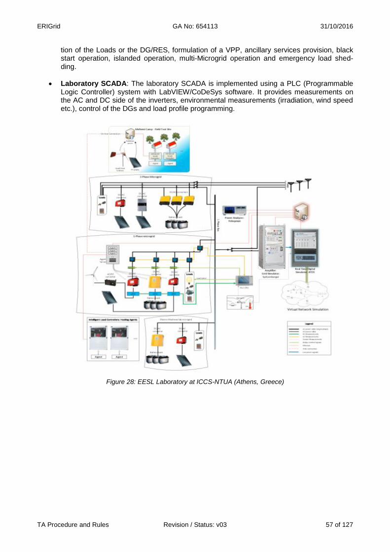
ERIGrid GA No: 654113 31/10/2016
TA Procedure and Rules Revision / Status: v03 57 of 127
tion of the Loads or the DG/RES, formulation of a VPP, ancillary services provision, black start operation, islanded operation, multi-Microgrid operation and emergency load shed-ding.
Laboratory SCADA: The laboratory SCADA is implemented using a PLC (Programmable Logic Controller) system with LabVIEW/CoDeSys software. It provides measurements on the AC and DC side of the inverters, environmental measurements (irradiation, wind speed etc.), control of the DGs and load profile programming.
Figure 28: EESL Laboratory at ICCS-NTUA (Athens, Greece)

ERIGrid GA No: 654113 31/10/2016
TA Procedure and Rules Revision / Status: v03 58 of 127
Figure 29: EESL Laboratory at ICCS-NTUA
Power Hardware-in-the-Loop (PHIL) simulation environment: The PHIL facility devel-oped at ICCS-NTUA provides an efficient environment for studying interactions between hardware DER power devices and various simulated networks. A rack of the commercially available Real Time Digital Simulator RTDS® is operated. A Switched-Mode Amplifier by Triphase and a linear amplifier by Spitzenberger & Spies (PAS 5000) are used as a Power Interfaces between the RTDS and physical equipment to perform PHIL simulation. The Tri-phase power electronic converter platform allows the user to design in Matlab/Simulink the control algorithms. PHIL experiments are performed, where hardware equipment (loads, PV inverters, etc.) are connected to simulated distribution networks. An irradiation sensor and an anemometer, provide input to simulated models in the RTDS in order to achieve realistic conditions.
Controller Hardware in the Loop (CHIL) simulation environment: In the context of its involvement with microgrids and dispersed generation, the research group is active in the development and study of advanced control algorithms for power electronic converters (DC/DC, DC/AC, AC/DC/AC, etc.). Based on the real-time simulator (RTDS) and a control-ler provided by Triphase, it is possible to thoroughly test control algorithms of power con-verters in an environment that reveals "hidden" weaknesses and faults in the design of these algorithms. Specifically, the design of the control algorithm is performed in the con-troller of Triphase while the power electronics are simulated in the RTDS. The communica-tion between the two systems is achieved through analog and digital signals.

ERIGrid GA No: 654113 31/10/2016
TA Procedure and Rules Revision / Status: v03 59 of 127
Figure 30: EESL Laboratory at ICCS-NTUA
Adaptive Protection System in Distribution Grids with DER Penetration in a HIL envi-ronment: In order to study new protection problems arising, a laboratory adaptive protec-tion system has been developed at ICCS-NTUA. The electrical networks are designed and studied in the real-time digital simulator (RTDS). Through analogue and digital signals the RTDS is connected to external devices, such as the industrial protection relay SEL-311B. The relay is programmed to protect a feeder of the electrical network and receive voltage and current signals from the RTDS. It also controls the status of the simulated breaker in the RTDS while its condition is fed back to the relay. All relays have overcurrent elements with 2-6 setting groups that are used for the adaptive protection implementation.

ERIGrid GA No: 654113 31/10/2016
TA Procedure and Rules Revision / Status: v03 60 of 127
Figure 31: EESL Laboratory at ICCS-NTUA
PV Inverter testing according to standards: The laboratory operates the necessary equipment to perform tests on photovoltaic inverters according to standards. A PV Simula-tor by Regatron (3x TopCon Quadro Programmable DC Power Supply) features fully con-trollable and customizable voltage-current characteristics (V-I), and a Linear Amplifier/Grid Simulator by Spitzenberger & Spies (PAS 5000 – 4 Quadrant Linear Amplifier 5kVA) ap-plies voltage (dips, introduction of harmonics etc.) and frequency variations on the inverter. In this way a testing environment is created for the testing of both the direct current (DC) and alternating current (AC) side of the inverter. By appropriately controlling the two simula-tors, the necessary conditions specified by the standards for PV inverter tests are repre-sented. The tests that can be carried out in the laboratory are:
o Static and Dynamic Maximum Power Point Tracking (MPPT) (EN 50530) o EMC tests (IEC 61000-3-2, Harmonic measurements 0-100KHz, etc.) o Connection requirements (VDE-AR-N 4105) o Fault ride through (VDE 0126-1-1) o Anti-islanding Requirements (In progress)
The electrical quantities (voltage, current, power, etc.) during the tests can be measured accurately and analyzed with the use of a Yokogawa WT3000 Power Analyzer.

ERIGrid GA No: 654113 31/10/2016
TA Procedure and Rules Revision / Status: v03 61 of 127
Flexible Power Electronics Configuration for Coupling RES & Storage: At EESL the simulation of distribution network under future scenarios is thoroughly analysed. An integral part of this process is the Triphase’s Distributed Power Modules that realize a scala-ble, flexible and open platform for rapid prototyping of power conversion and power system applications. The setup consists of a 15 kVA bidirectional active frontend (DC/AC), and a 15 kW bidirectional DC/DC converter consisting of 3 channels. The Power Modules are ful-ly reconfigurable and open. Researchers have access to all data and can change all the software (based on Matlab/Simulink) from the highest level (e.g. coordination and control of power flows between the storage and the grid) down to the lowest level (e.g. PWM control). Currently the module is operated as a 3ph inverter to interface a battery storage system or as a 1ph-3-leg back to back converter (AC/DC/AC) for power amplification. All converters are connected to a single DC bus which is accessible to external DC sources (e.g. Dc simu-lator). The open, reconfigurable and fully reprogrammable structure of the Power Modules can readily be adapted to new research areas.
Figure 32: EESL Laboratory at ICCS-NTUA
Axial flux generator bench testing facilities: The bench testing rig allows for the testing of axial flux generators of power up to 9kW and maximum diameter of up to 1m. With the use of a 60 HP DC motor, a DC bi-directional drive and a tachogenerator, the axial flux generators can be driven at different and constant revolutions per minute (RPM). Different loads can be applied to the generators such as a grid-tie inverter for grid connection or a 12/24/48V battery bank for battery charging modes, along with a diversion load controller and resistive load. In addition, a three phase ohmic load of maximum power 3.3kW can be connected directly to the generator. The experimental setup mentioned allows for a com-plete analysis of the generator’s behavior under different situations.
Residential Wind and Hydro Turbines construction: The study and simulation of resi-dential wind and hydro turbines for rural electrification applications follows local manufactur-ing which enables the user with the ability of local maintenance and immediate repairs of possible failures. In the workshop, small wind and hydro turbines are constructed from scratch. Up until now, residential wind turbines for battery charging and grid connection have been manufactured, with rotor diameters of up to 4.3 meters and a pico-hydro system of 500W.
Meltemi Test Site: ICCS-NTUA has access to the Meltemi site where a number of Distrib-uted Generators (DGs) are installed, including a 40kVA diesel generator, 4.5 kW photovol-taic panels and small residential wind turbines that can partially support the Meltemi camp-
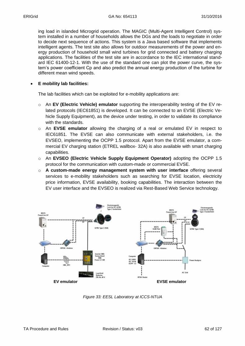
ERIGrid GA No: 654113 31/10/2016
TA Procedure and Rules Revision / Status: v03 62 of 127
ing load in islanded Microgrid operation. The MAGIC (Multi-Agent Intelligent Control) sys-tem installed in a number of households allows the DGs and the loads to negotiate in order to decide next sequence of actions. This system is a Java based software that implements intelligent agents. The test site also allows for outdoor measurements of the power and en-ergy production of household small wind turbines for grid connected and battery charging applications. The facilities of the test site are in accordance to the IEC international stand-ard IEC 61400-12-1. With the use of the standard one can plot the power curve, the sys-tem’s power coefficient Cp and also predict the annual energy production of the turbine for different mean wind speeds.
E mobility lab facilities:
The lab facilities which can be exploited for e-mobility applications are:
o An EV (Electric Vehicle) emulator supporting the interoperability testing of the EV re-
lated protocols (IEC61851) is developed. It can be connected to an EVSE (Electric Ve-
hicle Supply Equipment), as the device under testing, in order to validate its compliance
with the standards.
o An EVSE emulator allowing the charging of a real or emulated EV in respect to
IEC61851. The EVSE can also communicate with external stakeholders, i.e. the
EVSEO, implementing the OCPP 1.5 protocol. Apart from the EVSE emulator, a com-
mercial EV charging station (ETREL wallbox- 32A) is also available with smart charging
capabilities.
o An EVSEO (Electric Vehicle Supply Equipment Operator) adopting the OCPP 1.5
protocol for the communication with custom-made or commercial EVSE.
o A custom-made energy management system with user interface offering several
services to e-mobility stakeholders such as searching for EVSE location, electricity
price information, EVSE availability, booking capabilities. The interaction between the
EV user interface and the EVSEO is realized via Rest-Based Web Service technology.
EV emulator EVSE emulator
Figure 33: EESL Laboratory at ICCS-NTUA
ERIGrid GA No: 654113 31/10/2016
TA Procedure and Rules Revision / Status: v03 63 of 127
3 Services offered by the Research Infrastructure The main services offered by the above facilities are:
Performance of Power Hardware-in-Loop testing of DER devices integrated with the RTDS
simulator. MIMO PHIL tests can also be performed using the two power amplifiers of the
lab.
CHIL applications with the RTDS simulator and an external Triphase Target PC which al-
lows the design of the control algorithm in Matlab/Simulink and it’s testing in real time.
Testing both local and remote by Multi Agent System (MAS) technology and performance
of optimizations.
Fast testing of developed control algorithms (Matlab/Simulink) in flexible hardware power
electronic converters (DC/DC, DC/AC, AC/DC/AC) provided by Triphase
Power curve measurement of Small Wind Turbines
Small wind turbine generator testing
Testing and validation of DG components within the Microgrids operation
Testing commercial or custom made e-mobility products for their compliance with EV
standards/protocols (IEC61581, OCPP)
Developing and testing EV smart management algorithms in lab environment (microgrids)
Testing and validating EV integration within simulated distribution network in the RTDS
PV inverter testing according to standards
Testing of protection schemes with the RTDS
Steady state and dynamic simulations of power systems with high RES penetration: using
various in-house and commercial packages.
4 Brief description of the organization managing the Research Infrastructure The Institute of Communication and Computer Systems (ICCS) is a private law body associated with the Department of Electrical and Computer Engineering of the National Technical University of Athens (NTUA). ICCS has been established in 1989 by the Ministry of Education in order to carry research and development activities in the fields of telecommunication systems and computer systems and their applications in a variety of applications, such as electric power systems, software and hardware engineering, control systems and biomedical engineering. R&D staff of ICCS-NTUA consists of 40 members of staff of NTUA, 20 additional sen-ior researchers and 120 research students. Smart RUE is one of the Research Groups of ICCS. It belongs to the Electric Energy Systems La-boratory (EESL) of the School of Electrical and Computer Engineering of the National Technical
University of Athens. It was founded by Professor Nikos Hatziargyriou and operates under his su-pervision. It is composed of Professors, post-doctoral scientists, postgraduate students and highly specialized researchers and collaborators. It is technically and administratively supported by the personnel of EESL. The main activities of Smart RUE focus in research and technology development in the area of Smart Grids. The main Smart RUE activities deal with planning and operation of modern power systems characterized by high penetration of renewable energy sources, distributed generation and flexible loads. For the efficient solution of related problems advanced control and ICT technol-ogies are employed. Smart RUE has coordinated and participated in a large number of European and national R&D pro-

ERIGrid GA No: 654113 31/10/2016
TA Procedure and Rules Revision / Status: v03 64 of 127
jects and studies. It has organized several international Conferences, Seminars and workshops and it has published numerous papers in international journals and conference proceedings. Its members are active in several EU and international organizations. It maintains excellent connec-tions with many Universities, Research Centers, Utilities and Power Industries active in the area of Smart Grids both at national and international level. 5 Transnational Access conditions offered by ICCS-NTUA
For safety reasons, for critical applications, the users are not expected to operate the systems by themselves; even when safety instructions will be provided, tests will be carried out by staff of ICCS-NTUA. For the rest of applications and after ad-hoc training, the user group will have full access to the related facilities for the duration of the stay (with the support of ICCS-NTUA’s re-searchers and laboratory technicians when necessary). The scheduling of the experiments will be agreed and booked prior to the stay according to the availability of the involved staff and equipment. Administrative documentation for the access (contract, non-disclosure agreement, etc.) will comply with ERIGrid common indications.
In addition to the general corporate services (Internet connection, canteen, etc.) and the support and advice on accommodation and transportation to ICCS-NTUA infrastructure, the access being offered includes supervision and help of ICCS-NTUA staff:
As a complement to the pre-access contacts between the user group and ICCS-NTUA, the stay will start with an introductory meeting with a senior researcher for confirming the stay con-ditions (confidentiality, safety indications), scheduling the activities, explaining the on-site pro-cedures, clarifying the logistics and technical details.
Preparatory work: a laboratory technician will assist the users for the installation of the devices, electrical connections, use of the specific instrumentation, preparation of a test procedure (if necessary) on the basis of the users requests, and programming of the experimental condi-tions.
ICCS-NTUA’s researchers will support the realisation and follow-up of the experiments.
ICCS-NTUA’s researchers will support the results interpretation, data processing and analysis, and test report preparation.
Reimbursement of expenses: User expenses for the Transnational Access are paid by ERIGrid (EU H2020 Programme). This includes travels to Athens by plane, accommodation, daily subsistence, and daily transportation during the stay. For the user projects taking place in ICCS-NTUA, ICCS-NTUA will refund the stay expenses when the stay is finished: the user must declare the incurred expenses and present the invoices/receipts to ICCS-NTUA in order to get the refund. Reasonable expenses must be made by the user: travels will be made in economy class and con-ventional hotels (not luxury) or equivalent accommodation will be used. As an indication (it is not a daily allowance), a maximum subsistence fee of 60 €/person must be considered per day, exclud-ing the hotel cost (i.e. for meals, coffee etc.). The tickets for the transportation to and from NTUA (metro, bus) will be also reimbursed.
ERIGrid GA No: 654113 31/10/2016
TA Procedure and Rules Revision / Status: v03 65 of 127
6 Contact details for Research Infrastructure
Electric Energy Systems Laboratory (EESL) – ICCS-NTUA
Address: 9, Iroon Polytechniou Str., 157 73 Zografou Campus, Athens, Greece
Website: http://www.smartrue.gr/
For Management/Organization Issues: For Technical issues:
Nikos Hatziargyriou
Email:
Panos Kotsampopoulos
Email: [email protected]
Telephone:+30 2107721499

ERIGrid GA No: 654113 31/10/2016
TA Procedure and Rules Revision / Status: v03 66 of 127
Fraunhofer IWES Kassel
1 Research Infrastructure
Name of Infrastructure/Installation Test Center for Smart Grids and Electromobility (IWES-SysTec)
Location Fraunhofer IWES, Kassel, Germany
Web Site www.energiesystemtechnik.iwes.fraunhofer.de
2 Description of the Research Infrastructure In the IWES-SysTec test center for smart grids and electromobility, Fraunhofer IWES is developing and testing new equipment and operation strategies for smart low and medium voltage grids. In addition, investigations regarding grid integration and grid connection of electric vehicles and their power generated from renewable energy sources as well as photovoltaic systems, wind energy plants, storage and hybrid systems are carried out under realistic conditions here. A large open-air ground of approx. 80,000 m² offers sufficient space and very good conditions for solar and wind energy. Furthermore, the open-air ground provides configurable distribution grid sectors (low and medium voltage.
Figure 34: The main building of IWES-SysTec with the labs SysTec PNI and SysTec TPE
In the eastern area of the premises there is a hall presently with two laboratory divisions: one of the labs, which is entitled “SysTec PNI” includes a testing area for low and medium voltage converters or distribution grid equipment. There it is possible to develop and test the electrical properties and
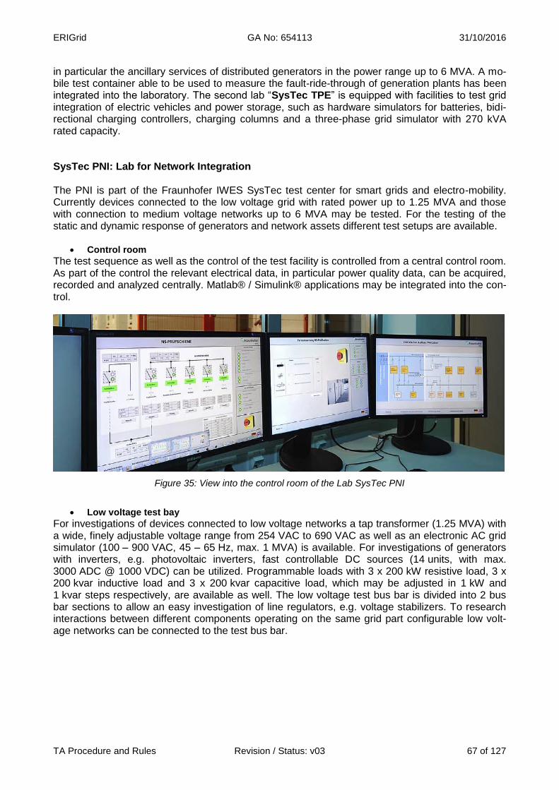
ERIGrid GA No: 654113 31/10/2016
TA Procedure and Rules Revision / Status: v03 67 of 127
in particular the ancillary services of distributed generators in the power range up to 6 MVA. A mo-bile test container able to be used to measure the fault-ride-through of generation plants has been integrated into the laboratory. The second lab “SysTec TPE” is equipped with facilities to test grid integration of electric vehicles and power storage, such as hardware simulators for batteries, bidi-rectional charging controllers, charging columns and a three-phase grid simulator with 270 kVA rated capacity. SysTec PNI: Lab for Network Integration The PNI is part of the Fraunhofer IWES SysTec test center for smart grids and electro-mobility. Currently devices connected to the low voltage grid with rated power up to 1.25 MVA and those with connection to medium voltage networks up to 6 MVA may be tested. For the testing of the static and dynamic response of generators and network assets different test setups are available.
Control room
The test sequence as well as the control of the test facility is controlled from a central control room. As part of the control the relevant electrical data, in particular power quality data, can be acquired, recorded and analyzed centrally. Matlab® / Simulink® applications may be integrated into the con-trol.
Figure 35: View into the control room of the Lab SysTec PNI
Low voltage test bay
For investigations of devices connected to low voltage networks a tap transformer (1.25 MVA) with a wide, finely adjustable voltage range from 254 VAC to 690 VAC as well as an electronic AC grid simulator (100 – 900 VAC, 45 – 65 Hz, max. 1 MVA) is available. For investigations of generators with inverters, e.g. photovoltaic inverters, fast controllable DC sources (14 units, with max. 3000 ADC @ 1000 VDC) can be utilized. Programmable loads with 3 x 200 kW resistive load, 3 x 200 kvar inductive load and 3 x 200 kvar capacitive load, which may be adjusted in 1 kW and 1 kvar steps respectively, are available as well. The low voltage test bus bar is divided into 2 bus bar sections to allow an easy investigation of line regulators, e.g. voltage stabilizers. To research interactions between different components operating on the same grid part configurable low volt-age networks can be connected to the test bus bar.

ERIGrid GA No: 654113 31/10/2016
TA Procedure and Rules Revision / Status: v03 68 of 127
Figure 36: Inside view into the Lab “SysTec PNI”
Medium voltage test bay
By utilizing digital test signal generators the secondary control technique (protection relays and controls) of generating units and network assets can be tested. For testing the transient behaviour a mobile test container (LVRT test facility) is available, which is integrated into the central lab con-trol as well. Since the test setup is inside a container, even on-site measurements and tests of complete power plants are possible. In this case the test facility is connected to the medium volt-age network between the equipment under test and the network connection point of the grid opera-tor. It produces voltage dips on the medium voltage side of the equipment under test without dis-turbing the public power grid. With the LVRT test facility 3-phase as well as 2-phase faults can be generated. 3 Services offered by the Research Infrastructure
Within IWES-SysTec Fraunhofer IWES offers the following services to research and industrial partners:
Examination of distributed generators (PV inverter, CHP units, diesel gen-sets etc.) in accordance with different grid connection guidelines (low voltage, medium voltage)
Field and laboratory tests of hybrid systems, small wind power plants and individual smart grid components as well as tests with hard-ware emulations under defined operating pro-files
Real time distribution grid simulations to test control centres and the grid integration of dis-tributed genera-tors, electric vehicles and power storage (hardware-in-the-loop)
Investigation of operating performance strat-egies for individual plants and hybrid systems (e.g. photovoltaic, storage facilities, heat pumps, combined heat and power)
Metrological examination of performance (tripping characteristic) of protection devices
Figure 37: MV Equipment under test: Power transformer with OLTC

ERIGrid GA No: 654113 31/10/2016
TA Procedure and Rules Revision / Status: v03 69 of 127
Measurements of power quality and analyses of performance
4 Brief description of the organization managing the Research Infrastructure The Fraunhofer-Gesellschaft undertakes applied research of direct utility to private and public en-terprise and of wide benefit to society. With a workforce of over 24,000, the Fraunhofer-Gesellschaft is Europe’s biggest organization for applied research, and currently operates a total of 67 institutes and research units. The research activities of the Fraunhofer Institute for Wind Energy and Energy System Technology IWES cover wind energy and the integration of renewable ener-gies into energy supply structures. Fraunhofer IWES was established in 2009 as a merger of the former Fraunhofer Center for Wind Energy and Maritime Engineering CWMT in Bremerhaven and the Institute for Solar Energy Technology ISET in Kassel. The Transnational Access will be conducted at Fraunhofer IWES Kassel within the R&D Division Systems Engineering and Distribution Grids, which has a long term experience in the systems technology for the utilization of renewable energies such as solar energy and wind energy as well as for other electricity generators, storage systems, and electrical vehicles. Converters and other equipment are being developed which support the new requirements of smart grids. The laboratory equipment of the Division Systems Engineering and Distribution Grids allows carrying out tests not only of smart grid equipment but also of complete sections of smart LV/MV-distribution networks using new ICT technologies. 5 Transnational Access conditions offered by Fraunhofer IWES All the offered experimental systems included in IWES-SysTec are in the same location in Roth-westen, near to Kassel, Germany.
For safety reasons the users are not expected to operate the lab infrastructures by themselves; even when safety instructions will be provided, experiments and tests will be carried out together with the staff of Fraunhofer IWES. The scheduling of the experiments will be agreed and booked prior to the stay according to the availability of the involved staff and equipment. Administrative documentation for the access (contract, non-disclosure agreement, etc.) will comply with ERIGrid common indications.
In addition to the general corporate services (Internet connection, etc.) and the help and advice on accommodation and transportation to Fraunhofer IWES’s infrastructures, the access being offered includes supervision and support of Fraunhofer IWES’s staff:
As a complement to the pre-access contacts between the user group and Fraunhofer IWES, the stay will start with an introductory meeting with a senior researcher for confirming the stay conditions (confidentiality, safety indications), scheduling the activities, explaining the on-site procedures, clarifying the logistics and technical details.
Preparatory work: a laboratory technician will assist the users for the installation of the devices, electrical connections, use of the specific instrumentation, preparation of a test procedure (if necessary) on the basis of the users requests, and programming of the experimental condi-tions.
Fraunhofer IWES’s researchers will support the realisation and follow-up of the experiments.
Fraunhofer IWES’s researchers will support the results interpretation, data processing and analysis.
In principle, a typical stay of 2 work weeks is foreseen for a single user group, but this period could be extended depending on the concrete user project. The user group (usually 2 persons) can use the infrastructure for the defined time.

ERIGrid GA No: 654113 31/10/2016
TA Procedure and Rules Revision / Status: v03 70 of 127
Reimbursement of expenses: User expenses for the Transnational Access are paid by ERIGrid (EU H2020 Programme). This includes travels to IWES-SysTec (Fraunhofer IWES) by plane, accommodation, daily subsistence, and daily transportation during the stay. Fraunhofer IWES will reimburse each User with a daily grant following the “Bundesreisekostengesetz” as a lump sum covering all expenses for subsist-ence during the stay at the Facility. For the user projects taking place in IWES-SysTec, Fraunhofer IWES will refund the stay expenses when the stay is finished: the user must declare the incurred expenses and present the invoic-es/receipts to Fraunhofer IWES in order to get the refund. Logical expenses must be made by the user: travels will be made in economy class and conven-tional hotels (not luxury) or equivalent accommodation will be used. As an indication (it is not a dai-ly allowance), a maximum subsistence fee of 94 €/ person must be considered per day. Lunch will be provided by Fraunhofer IWES free to the user. 6 Contact details for Research Infrastructure
Test Center for Smart Grids and Electromobility (IWES-SysTec) – Fraunhofer IWES
Address:Königstor 59– 34119 Kassel, Germany
Website:
For Management/Organization Issues: For Technical issues:
Dr. Thomas Degner
Tel.: +49 561 7294-232
E-mail:
Dr. Gunter Arnold
Tel.: +49 561 7294-231
E-mail:

ERIGrid GA No: 654113 31/10/2016
TA Procedure and Rules Revision / Status: v03 71 of 127
ORMAZABAL Corporate Technology
1 Research Infrastructure
Name of Infrastructure/Installation Demonstration & Experimentation Unit (UDEX)
Location ORMAZABAL Corporate Technology, Amorebieta, Spain
Web Site http://www.ormazabal.com/en/about-us/our-own-technology/technological-innovation-center
2 Description of the Research Infrastructure Demonstration and Experimentation Unit (UDEX), consists of an Experimental Grid designed as a platform to research, develop and verify equipment and systems in a real grid in a non-risk envi-ronment: 3500 m2 real-time experimentation network with over 15 km of underground cable and 450 m of overhead line. This configurable autonomous grid permits the reproduction of normal conditions and anomalous situations to produce real medium voltage operating conditions independent from the grid and at different power frequencies. The main purpose of the UDEX is to facilitate access to a smart grid network having a high degree of flexibility, independent of the utility network, for the development and testing of new technolo-gies. It is able to reproduce real conditions of existing worldwide grid topologies at different voltage levels and at different power frequencies. The UDEX management system (UMS) controls the operation of the infrastructure to run according to a certain strategy, physically connects/disconnects the elements, and changes the network to-pology, by means of fully automated operation. The facility allows the research and development of the connection, integration and validation of new technologies, assessment of the impact on the network, and the investigation of operation of the complete network.
Figure 38: UDEX at ORMAZABAL Corporate Technology (Amorebieta, Spain)

ERIGrid GA No: 654113 31/10/2016
TA Procedure and Rules Revision / Status: v03 72 of 127
Figure 39: UDEX at ORMAZABAL Corporate Technology
In addition, in the UDEX there are five special test cases with singular capabilities in the specific fields of voltage regulation, MV network compatibility, network diagnosis, powerline communica-tions, and smart metering:
Regulation of network voltages to maintain quality of supply affected by integration of renewables and/or significant intermittent loads: Functional validation of MV/LV volt-age regulating systems (e.g. on-load automatic tap changer) in real MV network environ-ment, with different MV Network Configurations and voltage levels - including Neutral con-figuration, Power Frequency (50-60Hz) MV Network Voltage Level (0-36kV)-.
Validation of correct functioning of IED systems in a real network in the face of tran-sient overvoltages / overcurrents occurring during typical switching operations in the MV network: Functional validation of IED’s in real network environment tested with dif-ferent MV Network Operations, especially during and after transients occurring during net-work switching. Neutral configuration, Power Frequency (50-60Hz), MV Network Voltage Level (0-36kV) can be controllable parameters.
Asset management of network and its components through online technologies: Functional validation of network diagnostic equipment and systems, from simple detection devices to complete monitoring systems, in real MV network environment. Especially fo-cused on validation of systems to do all or some of the following: Detection, analysis, identi-fication, localization and evaluation of defects arising from PD sources and the communica-tion of this data to supervision interface. Network and neutral configuration, Power Fre-quency (50-60Hz), MV Network Voltage Level (0-36kV), Measurement Bandwidth, defect type and location being controllable parameters to perform the assessment of the system.
Testing of functional compatibility of combined sensors with MV & PLC signal measurements in the Medium Voltage Networks: Simultaneous Compliance of Precision & communications performance of combined sensors, using a real distribution network with different components under test (Combined sensors, RTU, PLC modems, measurement cables, MV Network Configurations). Network and neutral configuration, Power Frequency (50-60Hz), MV Network Voltage Level (0-36kV), and Communications Bandwidth can be controllable parameters.
Testing of functional narrowband powerline communications in distribution net-works: Compliance with communications performance requirements, using a real distribu-tion network with different components under test (PLC modems/Data concentrators, Me-ters, Network Configurations, MV/LV Transformers, Switchgears, Sniffers). Network and neutral configuration, Power Frequency (50-60Hz), MV Network Voltage Level (0-36kV), and Communications Bandwidth can be controllable parameters. This system allows also to change the length and type of the LV lines and network topology, the number and type of

ERIGrid GA No: 654113 31/10/2016
TA Procedure and Rules Revision / Status: v03 73 of 127
meters, in such a way that not only individual meters can be tested but also entire meter systems and the interoperability performance.
Figure 40: UDEX at ORMAZABAL Corporate Technology
3 Services offered by the Research Infrastructure
Figure 41: UDEX at ORMAZABAL Corporate Technology
Important tool for the research, develop-ment and evaluation of new technologies for the future grid and for anticipating prob-lems, which may appear under the most realistic conditions.
UDEX’s concept consists of a highly con-figurable distribution network independent from the grid which allows the develop-ment and testing of new technologies, products & services in a safe and con-trolled environment, positioning Ormaza-bal at the high-end of world-class R&D ca-pabilities, providing the following services (but not limited to):
Electrical protections and network au-tomation.
Network diagnostic systems.
Power Line Communications (PLC).
AMI (Advanced Metering Infrastruc-tures)
Active demand management.
Integration of distributed and renewa-ble generation in the grid.
Bidirectional power flow.
Dynamic configuration of the distribu-tion network.
Electric vehicle integration in the distri-bution network.
Integration of energy storage systems.
Power electronics.
Power quality and efficiency.
Impact on the safety (EMF, step and touch voltages, short circuit behaviour

ERIGrid GA No: 654113 31/10/2016
TA Procedure and Rules Revision / Status: v03 74 of 127
4 Brief description of the organization managing the Research Infrastructure From the time Ormazabal was founded in 1967, we have been aware of the strategic importance of research applied to own technological development, and in this way offer quality products and ser-vices to the customers and consolidate the leading position in the world’s technology sector. The Research and Technology Center, managed by Ormazabal Corporate Technology (OCT), rep-resents an important leap in the company’s track record; a project that has long been desired and aspires to become a technical reference at an international level, in the field of electrical power dis-tribution networks. The Research and Technology Center becomes an essential element in R&D projects, with the purpose of acquiring and improving existing technologies and researching new ones. OCT’s facilities offer their services to the technological scientific sector for performing research testing and for developing and type testing products the electrical sector. Ormazabal is very active in national and international recognized electrical product and services for the distribution networks relevant for ERIGrid, contributing to the development of common visions, roadmaps and strategies for the energy sector and having an excellent perspective and vision of the future challenges. This networking structure is complemented by a large experience in national and international research projects based on the research and technology development capabili-ties of OCT. In addition to the UDEX infrastructure offered in ERIGrid, OCT has a high power la-boratory, a high voltage laboratory and a low voltage laboratory for equipment testing, being an accredited laboratory according to EN ISO/IEC 17025 for many testing activities. 5 Transnational Access conditions offered by OCT All the offered experimental systems included in the UDEX are located in the research and tech-nology center of ORMAZABAL Corporate Technology in Boroa (Amorebieta-Etxano), near Bilbao, Spain.
For safety reasons, for critical applications, the users are not expected to operate the systems by themselves; even when safety instructions will be provided, tests will be carried out by staff of OCT. For the rest of applications and after ad-hoc training, the user group will have full access to the related facilities for the duration of the stay (with the support of OCT’s researchers and labora-tory technicians when necessary). The scheduling of the experiments will be agreed and booked prior to the stay according to the availability of the involved staff and equipment. Administrative documentation for the access (contract, non-disclosure agreement, etc.) will comply with ERIGrid common indications.
In addition to the general corporate services (Internet connection, canteen, etc.) and the support and advice on accommodation and transportation to OCT’s infrastructure, the access being offered includes supervision and help of OCT’s staff:
As a complement to the pre-access contacts between the user group and OCT, the stay will start with an introductory meeting with a senior researcher for confirming the stay conditions (confidentiality, safety indications), scheduling the activities, explaining the on-site procedures, clarifying the logistics and technical details.
Preparatory work: a laboratory technician will assist the users for the installation of the devices, electrical connections, use of the specific instrumentation, preparation of a test procedure (if necessary) on the basis of the user’s requests, and programming of the experimental condi-tions.
OCT’s researchers will support the realisation and follow-up of the experiments.

ERIGrid GA No: 654113 31/10/2016
TA Procedure and Rules Revision / Status: v03 75 of 127
OCT’s researchers will support the results interpretation, data processing and analysis, and test report preparation
In principle, a typical stay of 1 month is foreseen for a single user group but this period could be extended depending on the concrete user project. The user group (usually 2 persons) can use the infrastructure for the defined time. Reimbursement of expenses: User expenses for the Transnational Access are paid by ERIGrid (EU H2020 Programme). This includes travels to UDEX (OCT) by plane, accommodation, daily subsistence, and daily transporta-tion during the stay. For the user projects taking place in UDEX, OCT will refund the stay expenses when the stay is finished: the user must declare the incurred expenses and present the invoices/receipts to OCT in order to get the refund. Logical expenses must be made by the user: travels will be made in economy class and conven-tional hotels (not luxury) or equivalent accommodation will be used. As an indication (it is not a dai-ly allowance), a maximum subsistence fee of 160 €/person must be considered per day. 6 Contact details for Research Infrastructure
ORMAZABAL Corporate Technology (OCT)
Address: Parque Empresarial Boroa · parcela 24. 48340 Amorebieta-Etxano. Bizkaia (Spain)
Website: http://www.ormazabal.com/en/about-us/our-own-technology/technological-innovation-center
For Management/Administration Issues: For Technical Issues:
Iñaki Orue
Tel.: +34 629 460 137
E-mail: [email protected]
Nabil Akroud
Tel.: +34 94 630 51 30
E-mail: [email protected]
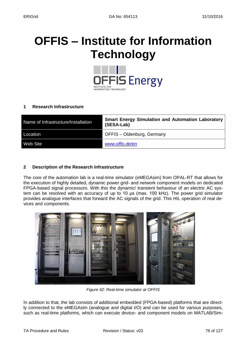
ERIGrid GA No: 654113 31/10/2016
TA Procedure and Rules Revision / Status: v03 76 of 127
OFFIS – Institute for Information Technology
1 Research Infrastructure
Name of Infrastructure/Installation Smart Energy Simulation and Automation Laboratory (SESA-Lab)
Location OFFIS – Oldenburg, Germany
Web Site www.offis.de/en
2 Description of the Research Infrastructure The core of the automation lab is a real-time simulator (eMEGAsim) from OPAL-RT that allows for the execution of highly detailed, dynamic power grid- and network component models on dedicated FPGA-based signal processors. With this the dynamic/ transient behaviour of an electric AC sys-tem can be resolved with an accuracy of up to 10 μs (max. 100 kHz). The power grid simulator provides analogue interfaces that forward the AC signals of the grid. This HIL operation of real de-vices and components.
Figure 42: Real-time simulator at OFFIS
In addition to that, the lab consists of additional embedded (FPGA-based) platforms that are direct-ly connected to the eMEGAsim (analogue and digital I/O) and can be used for various purposes, such as real-time platforms, which can execute device- and component models on MATLAB/Sim-

ERIGrid GA No: 654113 31/10/2016
TA Procedure and Rules Revision / Status: v03 77 of 127
ulink basis in real-time (similar to the power grid simulator), or as standard industry components that are able to implement standard-compliant controllers or even complex agent-based control strategies. The systems with the highest performance are additionally operated as substation plat-forms in order to realize control- and protection systems. A special feature of the SESA-Lab installation is the topology free allocation and combination of inputs and outputs. That means access and visibility can be controlled in a rule-based manner for the Ethernet- and EtherCATbased component-to-component communication. Furthermore, the an-alogue inputs and outputs of the real-time platforms can be virtually interconnected. This allows a flexible connection of the dynamic component models with different nodes of the real-time simula-tion without significant manual changeovers. The virtual and topology free connection even ena-bles the parallel operation of independent simulations/experiments in standard-compliant power system automation environments. Another part of the lab is a virtualization server that can provide virtual machines for mosaik-based (open source power/ICT simulation coordinator) simulations (lower-resolution parts of the analysed scenario that run conjointly in parallel with the hardware-based real-time simulation), development environments, or licensing servers for possible runtime environments. The external interface allows connections to research infrastructures provided by the University of Oldenburg, e.g., the HERO cluster (High-End Computing Resource Oldenburg) that can be used for significantly more exten-sive complex mosaik-based simulation scenarios that are co-simulated and synchronized with the hardware-based component simulations of the SESA-Lab. However, the interface foremost pro-vides the possibility to integrate infrastructures from external research- and cooperation partners into the SESA-Lab. This is of special interest for the functional integration of testing equipment for power electronics and components located at external universities and institutes – which is com-fortably to handle with mosaik. The SESA-Lab relies on integrated standard-compliant information- and process chains based on the IEC Common Information Model (CIM; IEC 61970/61968), IEC 61850, and the OPC Unified Architecture (UA). This covers the whole process starting in the (planned) control centre down to the controllers and various field devices. A control centre simulation has been added to the SESA-Lab environment realizing a transparent SCADA-based viewpoint and operation of the co-simulated (both hard- and software, remote and on-site facilities/components) system, as well as the protocol families covered by the IEC 60870, the industry standard for telecontrol and power system control. Extensions will mainly address two things: firstly, communication simulation in order to realistically influence message transfer times and communication reliability, and secondly, further up-scaling the existing infrastructure.
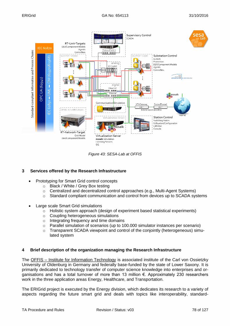
ERIGrid GA No: 654113 31/10/2016
TA Procedure and Rules Revision / Status: v03 78 of 127
Figure 43: SESA-Lab at OFFIS
3 Services offered by the Research Infrastructure
Prototyping for Smart Grid control concepts o Black / White / Grey Box testing o Centralized and decentralized control approaches (e.g., Multi-Agent Systems) o Standard compliant communication and control from devices up to SCADA systems
Large scale Smart Grid simulations o Holistic system approach (design of experiment based statistical experiments) o Coupling heterogeneous simulations o Integrating frequency and time domains o Parallel simulation of scenarios (up to 100.000 simulator instances per scenario) o Transparent SCADA viewpoint and control of the conjointly (heterogeneous) simu-
lated system 4 Brief description of the organization managing the Research Infrastructure The OFFIS – Institute for Information Technology is associated institute of the Carl von Ossietzky University of Oldenburg in Germany and federally base-funded by the state of Lower Saxony. It is primarily dedicated to technology transfer of computer science knowledge into enterprises and or-ganisations and has a total turnover of more than 13 million €. Approximately 230 researchers work in the three application areas Energy, Healthcare, and Transportation. The ERIGrid project is executed by the Energy division, which dedicates its research to a variety of aspects regarding the future smart grid and deals with topics like interoperability, standard-
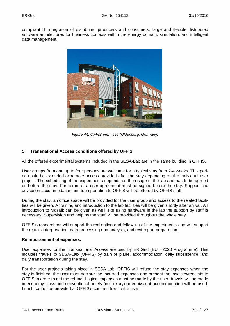
ERIGrid GA No: 654113 31/10/2016
TA Procedure and Rules Revision / Status: v03 79 of 127
compliant IT integration of distributed producers and consumers, large and flexible distributed software architectures for business contexts within the energy domain, simulation, and intelligent data management.
Figure 44: OFFIS premises (Oldenburg, Germany)
5 Transnational Access conditions offered by OFFIS All the offered experimental systems included in the SESA-Lab are in the same building in OFFIS. User groups from one up to four persons are welcome for a typical stay from 2-4 weeks. This peri-od could be extended or remote access provided after the stay depending on the individual user project. The scheduling of the experiments depends on the usage of the lab and has to be agreed on before the stay. Furthermore, a user agreement must be signed before the stay. Support and advice on accommodation and transportation to OFFIS will be offered by OFFIS staff. During the stay, an office space will be provided for the user group and access to the related facili-ties will be given. A training and introduction to the lab facilities will be given shortly after arrival. An introduction to Mosaik can be given as well. For using hardware in the lab the support by staff is necessary. Supervision and help by the staff will be provided throughout the whole stay. OFFIS’s researchers will support the realisation and follow-up of the experiments and will support the results interpretation, data processing and analysis, and test report preparation. Reimbursement of expenses: User expenses for the Transnational Access are paid by ERIGrid (EU H2020 Programme). This includes travels to SESA-Lab (OFFIS) by train or plane, accommodation, daily subsistence, and daily transportation during the stay. For the user projects taking place in SESA-Lab, OFFIS will refund the stay expenses when the stay is finished: the user must declare the incurred expenses and present the invoices/receipts to OFFIS in order to get the refund. Logical expenses must be made by the user: travels will be made in economy class and conventional hotels (not luxury) or equivalent accommodation will be used. Lunch cannot be provided at OFFIS’s canteen free to the user.

ERIGrid GA No: 654113 31/10/2016
TA Procedure and Rules Revision / Status: v03 80 of 127
6 Contact details for Research Infrastructure
Smart Energy Simulation and Automation Laboratory (SESA-Lab) – OFFIS
Address: Escherweg 2, 26121 Oldenburg, Germany
Website: http://www.offis.de/en
For Management/Organization Issues: For Technical issues:
Lars Fischer
Tel.: +49 441 9722 422
E-mail: [email protected]
Martin Büscher
Tel.: +49 441 9722 740
E-mail:

ERIGrid GA No: 654113 31/10/2016
TA Procedure and Rules Revision / Status: v03 81 of 127
Ricerca sul Sistema Energetico - RSE
1 Research Infrastructure
Name of Infrastructure/Installation Distributed Energy Resources Test Facility (RSE DER-TF)
Location Ricerca sul Sistema Energetico – RSE S.p.A.
Web Site www.rse-web.it
2 Description of the Research Infrastructure RSE DER-TF (Distributed Energy Resources Test Facility) is a real low voltage microgrid that in-terconnects different generators, storage systems and loads to develop studies and experimenta-tions on DERs and Smart Grid solutions. The Facility extends over an area of about 20000 m2, is interconnected to the MV Grid by means of a 800 kVA dedicated transformer (23 kV/400 V) and has an overall capacity of 350 kW (active power) and 300 kVAr (reactive power). Different types of DER generators are connected as PV Fields, Wind Generator, Diesel Generator and natural gas CHPs (Internal Combustion Engines). The facility has an overall storage capability of about 230 kWh based on different storage technologies as Lithium, Flow (Redox), High tem-perature Nickel-Sodium and Lead (VLRA) batteries interconnected to the grid with dedicated con-verters. Resistive, Inductive and Capacitive Loads (overall capability of about 90 kW, 70 kWAr in-ductive and 150 kWAr capacitive are connected to the grid in order to simulate different typologies of actual users loads). The microgrid is configurable (locally or remotely) at the interconnection board in order to obtain different grid topologies: radial grids and also meshed configurations. There’s also the opportunity to extend feeders till one kilometre. The microgrid is able to operate grid connected or in islanded mode thanks to specific droop control algorithms implemented in some converters. The interconnection board (main bars and all feeders) and all the DERs are provided with electrical measure equipment, set up to collect and analyse the experimental data derived from the field test.

ERIGrid GA No: 654113 31/10/2016
TA Procedure and Rules Revision / Status: v03 82 of 127
Figure 45: DER-TF at RSE (Milano, Italy)
A Supervision and Control system has been developed in order to monitor and control all installed resources. Different Energy Management and control functions have been implemented and can be used in order to fulfil with the requested objective (economic optimisation, renewable resources balancing, self-consumption, voltage control, state estimator). Resources control can be performed manually or in a full automated mode according to the different Microgrid control functions. New Manage-ment and control functions (also from third parties) can be easily integrated to DER Test Facility Control System. Communication has been developed mainly based on LAN Ethernet. Archive functions as data storage and retrieval are integrated in SCADA.

ERIGrid GA No: 654113 31/10/2016
TA Procedure and Rules Revision / Status: v03 83 of 127
Figure 46: DER-TF diagram
In addition, integrated to the AC microgrid, there are components and facilities that can extend the infrastructure testing capabilities as:
Low Voltage DC Microgrid (380 V, 100 kWe) capable to operate in islanding mode ore in-terconnected to the AC grid. The DC microgrid operates at nominal voltage of 380VDC with bi-directional interface inverter (100 kWE), two Zebra batteries (each 30kWp, 16kWh), two super-capacitors banks (each 30 kWp, 8 seconds), a PV emulator (30kWE), a DC fully con-trollable resistive load (30kW) connected to DC BUS by DC/DC converters and a DC pro-grammable load (30kW) directly connected to DC grid. The grid can operate in islanded mode or connected to the main AC grid (DER Test Facility).
Figure 47: LV DC Microgrid at DER-TF
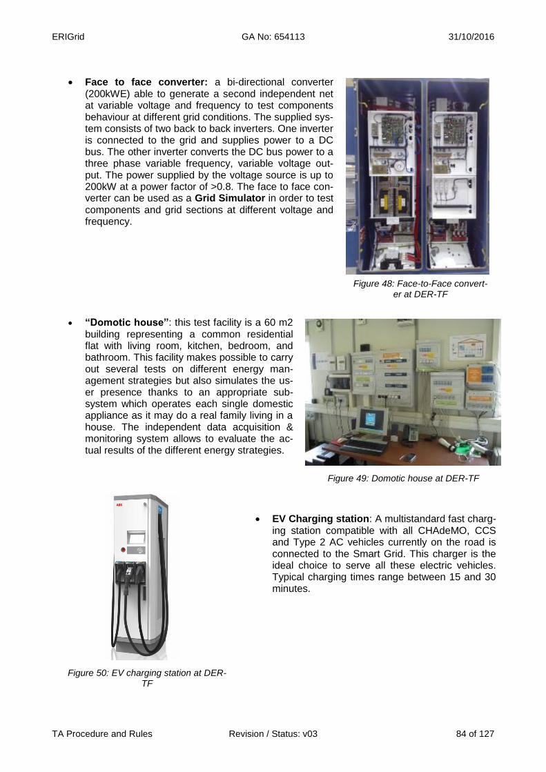
ERIGrid GA No: 654113 31/10/2016
TA Procedure and Rules Revision / Status: v03 84 of 127
Face to face converter: a bi-directional converter (200kWE) able to generate a second independent net at variable voltage and frequency to test components behaviour at different grid conditions. The supplied sys-tem consists of two back to back inverters. One inverter is connected to the grid and supplies power to a DC bus. The other inverter converts the DC bus power to a three phase variable frequency, variable voltage out-put. The power supplied by the voltage source is up to 200kW at a power factor of >0.8. The face to face con-verter can be used as a Grid Simulator in order to test components and grid sections at different voltage and frequency.
Figure 48: Face-to-Face convert-er at DER-TF
“Domotic house”: this test facility is a 60 m2
building representing a common residential flat with living room, kitchen, bedroom, and bathroom. This facility makes possible to carry out several tests on different energy man-agement strategies but also simulates the us-er presence thanks to an appropriate sub-system which operates each single domestic appliance as it may do a real family living in a house. The independent data acquisition & monitoring system allows to evaluate the ac-tual results of the different energy strategies.
Figure 49: Domotic house at DER-TF
Figure 50: EV charging station at DER-TF
EV Charging station: A multistandard fast charg-ing station compatible with all CHAdeMO, CCS and Type 2 AC vehicles currently on the road is connected to the Smart Grid. This charger is the ideal choice to serve all these electric vehicles. Typical charging times range between 15 and 30 minutes.

ERIGrid GA No: 654113 31/10/2016
TA Procedure and Rules Revision / Status: v03 85 of 127
SW Interface: the DER-TF SCADA is written in Lab-VIEW and can be interfaced with other any software for both measurements acquisition and device control. The available protocols for data access are the following:
o NI LabVIEW DataSocket protocol
o OPC DA protocol
o MODBUS TCP protocol
Figure 51: SW Interface at DER-TF
3 Services offered by the Research Infrastructure
In the Distributed Energy Resources Test Facility of RSE, the architecture and management sys-tem of the microgrid and the specific features of the described infrastructure provide the following services (but not limited to):
Development, optimization and testing of smart grid operation and control algorithms.
On grid and off grid (islanded) AC microgrid testing
DC microgrid testing (including management and control algorithms)
Characterisation and testing of Generators and Storage systems
Innovative instrumentation and component testing
AC/DC converters testing grid connected and in islanding operation
Management of EV charging station: testing of charging control and management algo-rithms
Domotical House management: testing of management and control strategies
4 Brief description of the organization managing the Research Infrastructure RSE (Ricerca sul Sistema Energetico) SpA (www.rse-web.it) is a Non-profit Research Organization established to take over funded research activities of national and international. About 350 techni-cians and researchers – and their main laboratories – carry out strategic research in the electricity and energy sector, with strong emphasis on experimental applications. The mission is to perform public interest R&D programs to address the national energy, environmental and economic goals, with an open view to the EU research initiatives. RSE SpA is currently 100% owned by GSE, “Ge-store Servizi Energetici” SpA, a public company entirely owned by the Italian Government. Competencies: On the basis of three-year Implementing Agreements for the research activities on the electric system with the Ministry of the Economic Development (MiSE), RSE SpA is mainly fi-nanced through a public fund related to the national electric system. RSE is currently cooperating in more than 60 international research projects and coordinates as leading partner more than 150 main research centres and companies in the energy field in Europe. RSE is moreover actively in-volved in supporting the Ministry of Economic Development with the aim of implementing the EU SET-Plan. RSE is active in several international network and technology platforms as the European Industrial Initiatives on Electricity Grids (EEGI, GRID+ coordinator) and Wind Energy (EEWI), the Joint Pro-gramme of the European Energy Research Alliance (EERA) on Smart Grids (as JP Coordinator) and Storage, and Implementing Agreements of the International Energy Agency (ISGAN Chairman

ERIGrid GA No: 654113 31/10/2016
TA Procedure and Rules Revision / Status: v03 86 of 127
and ISGAN/SIRFN member). It is also active in the CEN-CENELEC-ETSI Smart Grid Coordination Group and in several IEC and CIGRÉ working groups. RSE has a noticeable experience in re-search and experiments on Smart Grids, DER characterization and integration in distribution net-works. Among the others, RSE has coordinated the I3 project DERri, under the EC Research In-frastructures programme. The RSE DER-TF (managed and operated by the Power Generation Technologies and Materials Department) is an infrastructure available for all RSE researchers in order to develop and test Smart Grid and Microgrid concepts including management and control optimization, advanced power system architectures, DER and storages integration, electric mobility. In addition RSE DER-TF is used by several industries (in the aim of cooperation agreements) in order to develop and test with RSE new components and smart grid management and control functions. 5 Transnational Access conditions offered by RSE All the offered experimental systems included in the RSE DER_TF are located in the RSE premis-es in Milan, Italy – Via Rubattino, 54. For safety reasons, for critical applications, the users are not expected to operate the systems by themselves; even when safety instructions will be provided, tests will be operatively carried out by the staff of RSE closely supporting the external team of users. For the rest of applications, and previous ad-hoc training, the user group will have full access to the related facilities for the du-ration of the stay (with the support of RSE’s researchers and laboratory technicians when neces-sary). RSE may decide, for organizational or safety reasons, to limit the access in particular cir-cumstances. The stay of the users will be regulated by a specific User Team Contract, signed in advance by the Team reference person that will contain in detail of the access conditions agreed for the specific project. A template of the contract model will be provided by RSE to the Team of Users long before the stay at the infrastructure. The scheduling of the experiments will be agreed and scheduled prior to the stay according to the organization planning of RSE and the availability of the involved staff and equipment. Administrative documentation for the access (contract, non-disclosure agreement, etc.) and related procedures will comply with ERIGrid common indications. In addition to the general corporate services (Internet connection, canteen, etc.) and the support and advice on accommodation and transportation to RSE’s infrastructure, the access being offered includes supervision and help of RSE’s staff:
Introductory actions. An RSE Senior Engineer will be dedicated to the Team of Users, being the reference for all aspects related to their stay in RSE. As a complement to the pre-access contacts between the user group and RSE, the stay will start with an introductory meeting with the dedicated senior researcher for confirming the stay conditions (confidentiality, safety indica-tions), scheduling the activities, explaining the on-site procedures, clarifying the logistics and technical details.
Preparatory work. A laboratory technician will assist the users for the installation of the devices, electrical connections, use of the specific instrumentation, preparation of a test procedure (if necessary) on the basis of the users requests and compatibly with the organization and re-quirements of the testing infrastructure, and programming of the experimental conditions.
Testing implementation. RSE’s researchers will support the realisation and follow-up of the ex-periments and supervise the execution of the tests.
Post-testing support. RSE’s researchers will support the results interpretation, data processing and analysis, and test report preparation.

ERIGrid GA No: 654113 31/10/2016
TA Procedure and Rules Revision / Status: v03 87 of 127
In principle, a typical stay of 2 weeks is foreseen for a single users group. However, depending on the specific project and on its implementation, an extension of the stay period, or a break of the stay in following phases, whenever convenient, may be agreed before or during the execution of the project. The user group (usually 2 persons) can use the infrastructure limitedly to the agreed time. The us-ers will be requested to declare their use of the infrastructure by signing in an RSE form at the end of their stay basing on the final balance. Reimbursement of expenses: User’s live expenses for the Transnational Access are paid by ERIGrid (EU H2020 Programme). RSE will:
a) Provide for the lunches of the User, during the working days in RSE’s canteen
b) Reimburse travel expenditures of each User (one only return ticket per User, unless dif-ferently agreed for the specific project). RSE requests the User to provide preventive indication of the travel expenses to be incurred and to condition the reimbursement to its preventive approval; travels will be made in economy class.
c) Reimburse each User with a daily grant of 150 Euros/day as a lump sum covering all expenses for lodging and subsistence during the whole period of stay at the Facility (including working days and holidays).
RSE will basically reimburse the users expenses (as indicated in the previous points b) and c) at the end of the stay basing on the final balance: The user must declare the incurred expenses by signing RSE forms and submit invoices/receipts to RSE in order to get the reimbursement. 6 Contact details for Research Infrastructure
Distributed Energy Resources Test Facility (DER-TF) - RSE
Address: RSE SpA -Via Rubattino 54 – 20134 –Milan (Italy)
Website: www.rse-web.it
For Management/Organization and Technical Issues:
Maurizio Verga
Tel.: +39.2. 3992. 4765
E-mail:
Carlo Sandroni
Tel.: +39.2. 3992. 5869
E-mail:

ERIGrid GA No: 654113 31/10/2016
TA Procedure and Rules Revision / Status: v03 88 of 127
SINTEF Energy Research
1 Research Infrastructure
Name of Infrastructure/Installation National Smart Grid Laboratory (NSGL)
Location SINTEF Energy Research - Trondheim, Norway
Web Site https://www.sintef.no/en/sintef-energy/
2 Description of the Research Infrastructure The National Smart Grid Laboratory (NSGL) is located in Trondheim at the campus of the Nor-wegian University of Science and Technology (NTNU) and jointly operated by SINTEF and NTNU. The laboratory has been recently refurbished and is under upgrade with state of the art solu-tions/technologies. The laboratory mainly consists of three platforms: the smart network testing fa-cility, the smart house demonstration and the distributed energy storage infrastructure.
Smart network testing facility: The core of the National Smart Grid Laboratory is the smart net-work testing facility. The facility can provide a flexible and reconfigurable electrical layout for con-ducting experiments at low voltage levels (e.g. 400 V AC or 800 V DC). The electrical system can be configured to represent a distribution or transmission grid with high penetration of renewable units including storage units and power electronics converters. The laboratory is equipped to perform real time simulations of electrical systems and their controls. Three OPAL-RT units are available for parallel simulation. This enables the possibility of testing control algorithms or schemes with rapid prototyping techniques. More advanced features are the Hardware in the loop (HIL) and the Power Hardware in the loop (P-HIL) based on the OPAL-RT platform and a high bandwidth, six-leg configurable power converter (200 kW) acting as a power interface. The following components are available in the laboratory:
Over 250 m2 of laboratory space and possibility of running multiple experiments in parallel OPAL-RT units with cumulatively 10 cores activated 200 kW high-bandwidth power converter operating as a grid emulator (5 kHz large signal
bandwidth and 20 kHz small signal bandwidth) Several 20 kW and 60 kW two level converter units 50 kW generator-motor based on induction machine 20 kW synchronous generator with a synchronization panel as in small hydro plants A network equivalent for distribution grids with configurable line impedance and resistance
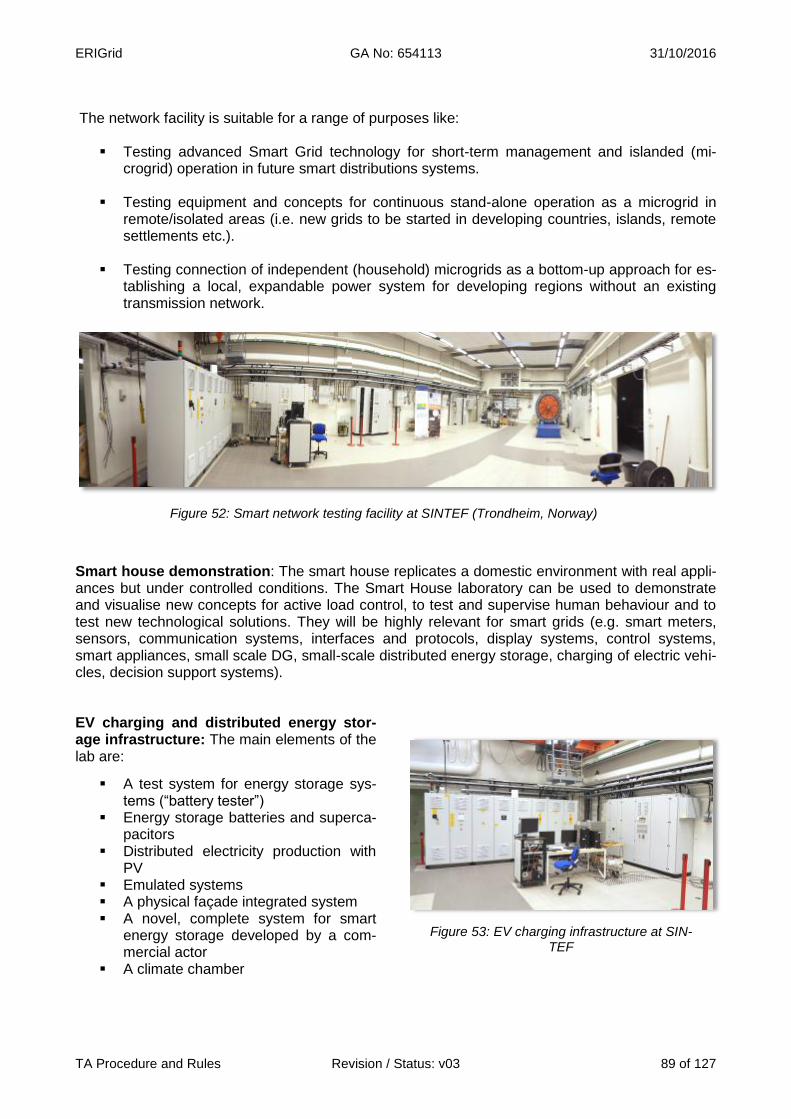
ERIGrid GA No: 654113 31/10/2016
TA Procedure and Rules Revision / Status: v03 89 of 127
The network facility is suitable for a range of purposes like:
Testing advanced Smart Grid technology for short-term management and islanded (mi-crogrid) operation in future smart distributions systems.
Testing equipment and concepts for continuous stand-alone operation as a microgrid in
remote/isolated areas (i.e. new grids to be started in developing countries, islands, remote settlements etc.).
Testing connection of independent (household) microgrids as a bottom-up approach for es-
tablishing a local, expandable power system for developing regions without an existing transmission network.
Figure 52: Smart network testing facility at SINTEF (Trondheim, Norway)
Smart house demonstration: The smart house replicates a domestic environment with real appli-ances but under controlled conditions. The Smart House laboratory can be used to demonstrate and visualise new concepts for active load control, to test and supervise human behaviour and to test new technological solutions. They will be highly relevant for smart grids (e.g. smart meters, sensors, communication systems, interfaces and protocols, display systems, control systems, smart appliances, small scale DG, small-scale distributed energy storage, charging of electric vehi-cles, decision support systems). EV charging and distributed energy stor-age infrastructure: The main elements of the lab are:
A test system for energy storage sys-tems (“battery tester”)
Energy storage batteries and superca-pacitors
Distributed electricity production with PV
Emulated systems A physical façade integrated system A novel, complete system for smart
energy storage developed by a com-mercial actor
A climate chamber
Figure 53: EV charging infrastructure at SIN-TEF

ERIGrid GA No: 654113 31/10/2016
TA Procedure and Rules Revision / Status: v03 90 of 127
Laboratory concept:
Real time sim-ulated power systems and controls (RTSPC)
200 kVA power supply inter-face Integrating RTSPC and PPSC
Physical pow-er systems and controls (PPSC)
Smart home / smart Building
Co
ntr
ol c
en
tre
(s
)
Energy stor-age PV, EV
Measurements infrastructure
Communication infrastructure
Data access (remote real time access, database access)
Figure 54: NSGL concept at SINTEF
3 Services offered by the Research Infrastructure
Figure 55: NSGL equipment at SINTEF
The National Smart Grid laboratory supports:
Smart transmission grids HVDC grids Smart active distribution grids Micro grids Integration of Smart grids, smart houses and
smart industries Integration of renewables (large scale, DG) Smart Grid and home automation Smart electricity use Electrification of transport Energy storage in Smart Grids Energy conversion in Smart Grids Power system stability in Smart Grids Monitoring, control and automation in Smart
Grids Communication technologies for Smart grids Information security and privacy in Smart grids Reliability challenges in Smart Grids - dependen-
cies of Power Grid and ICT Smart grid software Big data management and analytics in Smart
grids

ERIGrid GA No: 654113 31/10/2016
TA Procedure and Rules Revision / Status: v03 91 of 127
4 Brief description of the organization managing the Research Infrastructure SINTEF Energy Research has completed and participated in many national and transnational pro-jects dealing with research related to energy systems. This involves e.g. market studies, energy system modelling and simulation as well as the small and large-scale integration of renewable en-ergy systems into the grid. The department is also responsible for research and development of several market simulation and hydrothermal scheduling models that are used by almost all of the Scandinavian market players, TSOs and the Norwegian regulator. A special part of this is the work with smart grids, channelled in the group of Active Grids. The group has a long experience with power quality and reliability measurement and management, end-user characterisation, and active use of new communication technology and innovative market solutions. SINTEF Energy Research is developing solutions and systems in the fields of power production, conversion, transmission and distribution, and the efficient end use of energy. A substantial part of the institutes R&D and demo activities are within the electrical power engineering domain. By Jan-uary 2014, SINTEF Energy Research had a staff of approx. 240 persons. In cooperation with Nor-wegian University of Science and Technology (NTNU), we have 7000 m2 of modern laboratories available for research, development and education. In 2012, the Company participated in 25 EU projects and coordinated three of them. In addition, we actively participate in a number of the EU’s technology platforms, which design the strategies related to our various disciplinary areas. The main tasks of SINTEF Energy Research within ERIGrid includes holistic system integration, implementation and demonstration of use cases/scenarios. Also, provisioning of the National Smart Grid Laboratory for Trans-national Access (TA). 5 Transnational Access conditions offered by SINTEF The National Smart Grid Laboratory is located at Sem Sælands vei 11, Trondheim, Norway.
For safety reasons, for critical applications, the users are not expected to operate the systems by themselves; even when safety instructions will be provided, tests will be carried out by staff of SIN-TEF. For the rest of applications and after ad-hoc training, the user group will have full access to the related facilities for the duration of the stay (with the support of SINTEF’s researchers and la-boratory technicians when necessary). The scheduling of the experiments will be agreed and booked prior to the stay according to the availability of the involved staff and equipment. Adminis-trative documentation for the access (contract, non-disclosure agreement, etc.) will comply with ERIGrid common indications.
In addition to the general corporate services (internet connection, canteen, etc.) and the support and advice on accommodation and transportation to SINTEF’s infrastructure, the access being of-fered includes supervision and help of SINTEF’s staff: As a complement to the pre-access contacts between the user group and SINTEF, the stay will
start with an introductory meeting with a senior researcher for confirming the stay conditions (confidentiality, safety indications), scheduling the activities, explaining the on-site procedures, clarifying the logistics and technical details.
Preparatory work: a laboratory technician will assist the users for the installation of the devices, electrical connections, use of the specific instrumentation, preparation of a test procedure (if necessary) based on the users requests, and programming of the experimental conditions.
The guest researcher will be placed within the building of SINTEF Energy Research and gets access to the lab facilities.
SINTEF’s researchers will support the realisation and follow-up of the experiments.

ERIGrid GA No: 654113 31/10/2016
TA Procedure and Rules Revision / Status: v03 92 of 127
SINTEF’s researchers will support the results interpretation, data processing and analysis, and test report preparation
In principle, a typical stay of 1 month is foreseen for a single user group but this period could be extended depending on the concrete user project. The user group (usually 2 persons) can use the infrastructure for the defined time. Reimbursement of expenses: User expenses for the Transnational Access are paid by ERIGrid (EU H2020 Programme). This includes travels to NSGL (SINTEF Energy Research) by plane, accommodation, daily subsistence, and daily transportation during the stay. For the user projects taking place in NSGL, SINTEF will refund the stay expenses when the stay is finished: the user must declare the incurred expenses and present the invoices/receipts to SINTEF in order to get the refund. Logical expenses must be made by the user: travels will be made in economy class and conven-tional hotels (not luxury) or equivalent accommodation will be used. As an indication (it is not a dai-ly allowance), a maximum subsistence fee of 160 €/person must be considered per day. 6 Contact details for Research Infrastructure
National Smart Grid Laboratory (NSGL) – SINTEF Energy Research
Address: SINTEF - Sem Sælands vei 11, 7034, Trondheim, Norway
Website: https://www.sintef.no/en/sintef-energy/
For Management/Organization Issues: For Technical issues:
Boye A. Høverstad
Tel.: +4795154202
E-mail: [email protected]
Kjell Ljøkelsøy
Tel.: +4790194173
E-mail:
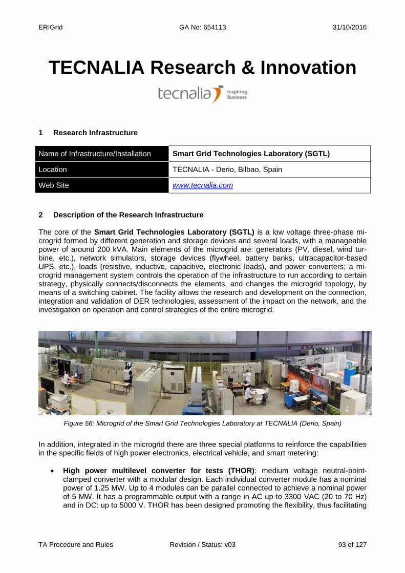
ERIGrid GA No: 654113 31/10/2016
TA Procedure and Rules Revision / Status: v03 93 of 127
TECNALIA Research & Innovation
1 Research Infrastructure
Name of Infrastructure/Installation Smart Grid Technologies Laboratory (SGTL)
Location TECNALIA - Derio, Bilbao, Spain
Web Site www.tecnalia.com
2 Description of the Research Infrastructure The core of the Smart Grid Technologies Laboratory (SGTL) is a low voltage three-phase mi-crogrid formed by different generation and storage devices and several loads, with a manageable power of around 200 kVA. Main elements of the microgrid are: generators (PV, diesel, wind tur-bine, etc.), network simulators, storage devices (flywheel, battery banks, ultracapacitor-based UPS, etc.), loads (resistive, inductive, capacitive, electronic loads), and power converters; a mi-crogrid management system controls the operation of the infrastructure to run according to certain strategy, physically connects/disconnects the elements, and changes the microgrid topology, by means of a switching cabinet. The facility allows the research and development on the connection, integration and validation of DER technologies, assessment of the impact on the network, and the investigation on operation and control strategies of the entire microgrid.
Figure 56: Microgrid of the Smart Grid Technologies Laboratory at TECNALIA (Derio, Spain)
In addition, integrated in the microgrid there are three special platforms to reinforce the capabilities in the specific fields of high power electronics, electrical vehicle, and smart metering:
High power multilevel converter for tests (THOR): medium voltage neutral-point-clamped converter with a modular design. Each individual converter module has a nominal power of 1.25 MW. Up to 4 modules can be parallel connected to achieve a nominal power of 5 MW. It has a programmable output with a range in AC up to 3300 VAC (20 to 70 Hz) and in DC: up to 5000 V. THOR has been designed promoting the flexibility, thus facilitating
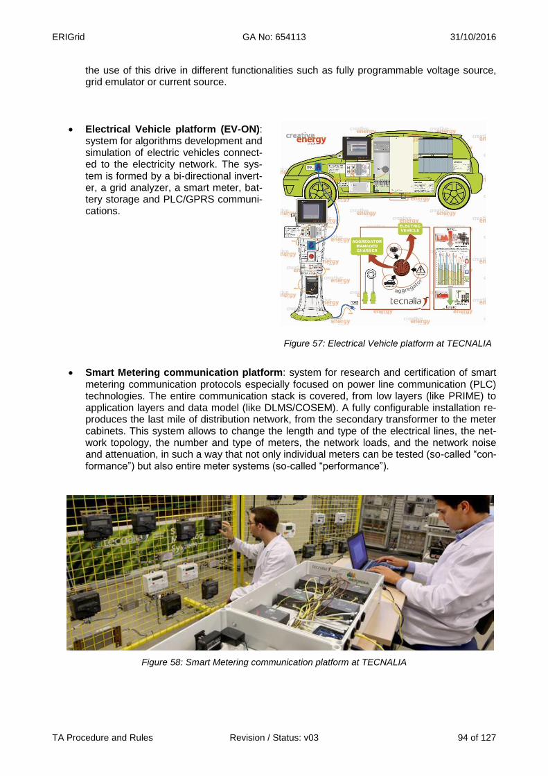
ERIGrid GA No: 654113 31/10/2016
TA Procedure and Rules Revision / Status: v03 94 of 127
the use of this drive in different functionalities such as fully programmable voltage source, grid emulator or current source.
Electrical Vehicle platform (EV-ON): system for algorithms development and simulation of electric vehicles connect-ed to the electricity network. The sys-tem is formed by a bi-directional invert-er, a grid analyzer, a smart meter, bat-tery storage and PLC/GPRS communi-cations.
Figure 57: Electrical Vehicle platform at TECNALIA
Smart Metering communication platform: system for research and certification of smart metering communication protocols especially focused on power line communication (PLC) technologies. The entire communication stack is covered, from low layers (like PRIME) to application layers and data model (like DLMS/COSEM). A fully configurable installation re-produces the last mile of distribution network, from the secondary transformer to the meter cabinets. This system allows to change the length and type of the electrical lines, the net-work topology, the number and type of meters, the network loads, and the network noise and attenuation, in such a way that not only individual meters can be tested (so-called “con-formance”) but also entire meter systems (so-called “performance”).
Figure 58: Smart Metering communication platform at TECNALIA
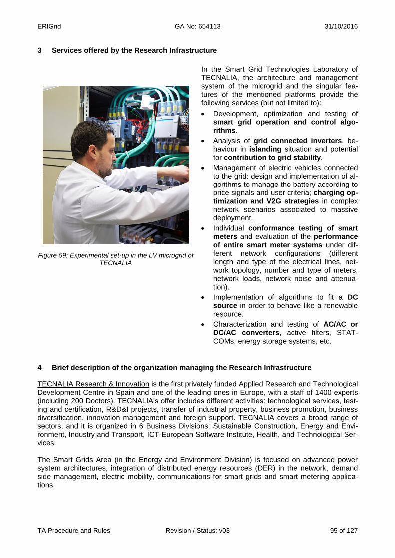
ERIGrid GA No: 654113 31/10/2016
TA Procedure and Rules Revision / Status: v03 95 of 127
3 Services offered by the Research Infrastructure
Figure 59: Experimental set-up in the LV microgrid of TECNALIA
In the Smart Grid Technologies Laboratory of TECNALIA, the architecture and management system of the microgrid and the singular fea-tures of the mentioned platforms provide the following services (but not limited to):
Development, optimization and testing of smart grid operation and control algo-rithms.
Analysis of grid connected inverters, be-haviour in islanding situation and potential for contribution to grid stability.
Management of electric vehicles connected to the grid: design and implementation of al-gorithms to manage the battery according to price signals and user criteria; charging op-timization and V2G strategies in complex network scenarios associated to massive deployment.
Individual conformance testing of smart meters and evaluation of the performance of entire smart meter systems under dif-ferent network configurations (different length and type of the electrical lines, net-work topology, number and type of meters, network loads, network noise and attenua-tion).
Implementation of algorithms to fit a DC source in order to behave like a renewable resource.
Characterization and testing of AC/AC or DC/AC converters, active filters, STAT-COMs, energy storage systems, etc.
4 Brief description of the organization managing the Research Infrastructure TECNALIA Research & Innovation is the first privately funded Applied Research and Technological Development Centre in Spain and one of the leading ones in Europe, with a staff of 1400 experts (including 200 Doctors). TECNALIA’s offer includes different activities: technological services, test-ing and certification, R&D&I projects, transfer of industrial property, business promotion, business diversification, innovation management and foreign support. TECNALIA covers a broad range of sectors, and it is organized in 6 Business Divisions: Sustainable Construction, Energy and Envi-ronment, Industry and Transport, ICT-European Software Institute, Health, and Technological Ser-vices. The Smart Grids Area (in the Energy and Environment Division) is focused on advanced power system architectures, integration of distributed energy resources (DER) in the network, demand side management, electric mobility, communications for smart grids and smart metering applica-tions.
ERIGrid GA No: 654113 31/10/2016
TA Procedure and Rules Revision / Status: v03 96 of 127
TECNALIA is very active in national and international platforms and networks relevant for ERIGrid, (EERA, ISGAN-SIRFN, EUREC, FUTURED, etc.), contributing to the development of common vi-sions, roadmaps and strategies for the energy sector and having an excellent perspective and vi-sion of the future challenges. This networking structure is complemented by a large experience in national and international research projects on decentralised energy and smart grids. In addition to the SGTL infrastructure offered in ERIGrid, TECNALIA has a high power laboratory, a high voltage laboratory and a low voltage laboratory for equipment testing, being an accredited laboratory ac-cording to EN ISO/IEC 17025 for many testing activities. 5 Transnational Access conditions offered by TECNALIA All the offered experimental systems included in the SGTL are in the same building in Derio, near Bilbao, Spain.
For safety reasons, for critical applications, the users are not expected to operate the systems by themselves; even when safety instructions will be provided, tests will be carried out by staff of TECNALIA. For the rest of applications and after ad-hoc training, the user group will have full access to the related facilities for the duration of the stay (with the support of TECNALIA’s re-searchers and laboratory technicians when necessary). The scheduling of the experiments will be agreed and booked prior to the stay according to the availability of the involved staff and equipment. Administrative documentation for the access (contract, non-disclosure agreement, etc.) will comply with ERIGrid common indications.
In addition to the general corporate services (Internet connection, canteen, etc.) and the support and advice on accommodation and transportation to TECNALIA’s infrastructure, the access being offered includes supervision and help of TECNALIA’s staff:
As a complement to the pre-access contacts between the user group and TECNALIA, the stay will start with an introductory meeting with a senior researcher for confirming the stay condi-tions (confidentiality, safety indications), scheduling the activities, explaining the on-site proce-dures, clarifying the logistics and technical details.
Preparatory work: a laboratory technician will assist the users for the installation of the devices, electrical connections, use of the specific instrumentation, preparation of a test procedure (if necessary) on the basis of the users requests, and programming of the experimental condi-tions.
TECNALIA’s researchers will support the realisation and follow-up of the experiments.
TECNALIA’s researchers will support the results interpretation, data processing and analysis, and test report preparation
In principle, a typical stay of 1 month is foreseen for a single user group but this period could be extended depending on the concrete user project. The user group (usually 2 persons) can use the infrastructure for the defined time. Reimbursement of expenses: User expenses for the Transnational Access are paid by ERIGrid (EU H2020 Programme). This includes travels to SGTL (TECNALIA) by plane, accommodation, daily subsistence, and daily transportation during the stay. For the user projects taking place in SGTL, TECNALIA will refund the stay expenses when the stay is finished: the user must declare the incurred expenses and present the invoices/receipts to TEC-NALIA in order to get the refund.

ERIGrid GA No: 654113 31/10/2016
TA Procedure and Rules Revision / Status: v03 97 of 127
Logical expenses must be made by the user: travels will be made in economy class and conven-tional hotels (not luxury) or equivalent accommodation will be used. As an indication (it is not a dai-ly allowance), a maximum subsistence fee of 160 €/person must be considered per day. Lunch will be provided at TECNALIA’s canteen free to the user. 6 Contact details for Research Infrastructure
Smart Grid Technologies Laboratory (SGTL) - TECNALIA
Address: Parque Tecnológico de Bizkaia. C/ Geldo, Edificio 700 – 48160 Derio, Spain
Website: www.tecnalia.com
For Management/Organization Issues: For Technical issues:
Emilio Rodríguez
Tel.: +34 667 119788
E-mail: [email protected]
Julia Merino
Tel.: +34 664 116639
E-mail:

ERIGrid GA No: 654113 31/10/2016
TA Procedure and Rules Revision / Status: v03 98 of 127
DELFT UNIVERSITY OF TECHNOLOGY
1 Research Infrastructure
Name of Infrastructure/Installation Real Time Digital Simulator Lab (RTDS)
Location TU Delft- Delft, The Netherlands
Web Site http://www.tudelft.nl/en/
2 Description of the Research Infrastructure The RTDS installation at TU Delft consists of 8 racks with 10 PB5 and 36 3PC cards, capable of simulating grids in 2 µs and 50 µs step size. Additionally the racks have analog/digital I/O, remote I/O, two GTNetx2, and one GTSync card. The RTDS Simulator allows to test protection and con-trols in real time, where an hour in the real world equals an hour in the simulator. Utilizing modular custom computing hardware and software, simulations performed encompass results from DC up to electromagnetic transients. Inherently, these results include information regarding the system load flow and transient stability, as well as that of harmonics and faster disturbances.
Figure 60: Real Time Digital Simulator Laboratory at TUDelft (Delft, The Netherlands)

ERIGrid GA No: 654113 31/10/2016
TA Procedure and Rules Revision / Status: v03 99 of 127
3 Services offered by the Research Infrastructure The major applications of the RTDS include:
Equipment can be thoroughly test-driven and customized.
New power system network designs or upgrades can be evaluated and accurately tested.
Black box real-world equipment (e.g. closed-source controllers) can be tested and integrat-ed in larger test scenarios without having a model.
Interoperability of multi-vendor installation can be validated.
Models and real implementations (products) of components can be compared.
Closed-loop testing of protective relays and control systems.
Studying general AC system operation including behaviour of generation and transmission systems.
Investigating dynamic power system equipment interaction.
Studying interaction between integrated AC/DC systems.
Integration and operation of distributed generation and renewables.
Investigation and testing of SMART Grid initiatives including wide area protection and con-trol.
Testing of control system of converter based equipment.
Figure 61: Real Time Digital Simulator at TUDelft

ERIGrid GA No: 654113 31/10/2016
TA Procedure and Rules Revision / Status: v03 100 of 127
4 Brief description of the organization managing the Research Infrastructure Technische Universiteit Delft (TU Delft) is the largest and oldest Dutch public technological uni-versity, located in Delft, Netherlands. It has eight faculties and numerous research institutes. It hosts over 19,000 students (undergraduate and postgraduate), more than 3,300 scientists, and more than 2,200 support and management staff.
The RTDS facility is within the Intelligent Electrical Power Grid (IEPG) group of the Electrical Sustainable Energy (ESE) department. The field of the Intelligent Electrical Power Grids research program covers the generation, trans-mission and distribution of electrical energy, and a characteristic is the system-oriented approach. Our research program covers the three different time scales for which power systems are usually studied: transient, dynamic and steady state behaviour of power systems. The area of this re-search program is concerned with the technical, economical and societal performance of the elec-tricity supply system. Theoretical and technological limits of current and future power systems and components are investigated taking into account the changing operating environment, e.g. the large-scale introduction of renewable and distributed energy sources and the application of new and sustainable technologies. 5 Transnational Access conditions offered by TU Delft The conditions of the Transnational Access offered by TU Delft are:
Half of the rack must stay free for our other projects.
Maximum 6 people are allowed.
Guests have to sign a hospitality declaration for the stay at TU Delft. Reimbursement of expenses: Travel expenses for Transnational Access (TA) are paid by the EU H2020 project ERIGrid. Dedi-cated project budget is reserved for the hosting institution to cover travel and staying expenses for TA guests. Travel and stay is expected to be based on the most economical options.
ERIGrid GA No: 654113 31/10/2016
TA Procedure and Rules Revision / Status: v03 101 of 127
6 Contact details for Research Infrastructure
Real Time Digital Simulator Laboratory
Address: TU Delft, EEMCS Building, Intelligent Power Electrical Grids
Room LB 03.260, Mekelweg 4, 2628CD Delft, The Netherlands
Website: www.tudelft.nl/en/
Contact Persons:
Peter Palensky
Tel.: +31 15 27 88341
E-mail:
Arjen van der Meer
Tel.: +31 15 27 88007
E-mail:
Rishabh Bhandia
Tel.: +31 15 27 83223
E-mail:
ERIGrid GA No: 654113 31/10/2016
TA Procedure and Rules Revision / Status: v03 102 of 127
Distribution Network and Protection (D-NAP) Laboratory
University of Strathclyde
1 Research Infrastructure
Name of Infrastructure/Installation Distribution Network and Protection (D-NAP) Laboratory
Location Glasgow, United Kingdom
Web Site https://www.strath.ac.uk/research/subjects/electronicelectricalengineering/instituteforenergyampenvironment/advancedelectricalsystems/
2 Description of the Research Infrastructure
Housed in a £90 M state of the art research and knowledge exchange environment, the laboratory contains a reconfigurable 400 V three-phase AC power network with multiple controllable voltage supplies and loads with flexible control systems and interfaces. The laboratory has power hardware-in-the-loop (PHIL) and controller hardware-in-the-loop (CHIL) capabilities. The network and devices are used to test and demonstrate smart grid technologies within a controlled environment, and under steady-state and abnormal conditions. Typical areas of research include: distributed control, future power systems with high penetrations of converters, control and communications integration, islanded (and auto-islanding) power systems, and dynamic power systems (e.g. marine/emergency).
There are four modes of operation of this facility: power hardware in the loop simulation; pre-set scenario playback; direct grid connection; and islanded system operation. The laboratory network is designed such that it can be split into three separate power islands under independent control, or connected together as an interconnected system. This provides a high degree of flexibility enabling many different land-based or marine scenarios to be demonstrated.
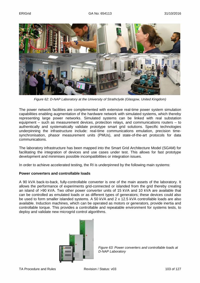
ERIGrid GA No: 654113 31/10/2016
TA Procedure and Rules Revision / Status: v03 103 of 127
Figure 62: D-NAP Laboratory at the University of Strathclyde (Glasgow, United Kingdom)
The power network facilities are complemented with extensive real-time power system simulation capabilities enabling augmentation of the hardware network with simulated systems, which thereby representing large power networks. Simulated systems can be linked with real substation equipment – such as measurement devices, protection relays, and communications routers – to authentically and systematically validate prototype smart grid solutions. Specific technologies underpinning the infrastructure include: real-time communications emulation, precision time-synchronisation, phasor measurement units (PMUs), and state-of-the-art protocols for data communications.
The laboratory infrastructure has been mapped into the Smart Grid Architecture Model (SGAM) for facilitating the integration of devices and use cases under test. This allows for fast prototype development and minimises possible incompatibilities or integration issues.
In order to achieve accelerated testing, the RI is underpinned by the following main systems:
Power converters and controllable loads
A 90 kVA back-to-back, fully-controllable converter is one of the main assets of the laboratory. It allows the performance of experiments grid-connected or islanded from the grid thereby creating an island of >90 kVA. Two other power converter units of 15 kVA and 10 kVA are available that can be controlled as emulated loads or as different types of generators; these devices could also be used to form smaller islanded systems. A 50 kVA and 2 x 12.5 kVA controllable loads are also available. Induction machines, which can be operated as motors or generators, provide inertia and controllable torque. This provides a controllable and repeatable environment for systems tests, to deploy and validate new microgrid control algorithms.
Figure 63: Power converters and controllable loads at D-NAP Laboratory
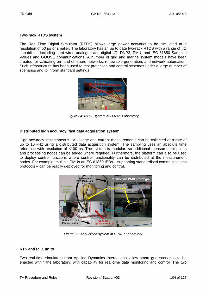
ERIGrid GA No: 654113 31/10/2016
TA Procedure and Rules Revision / Status: v03 104 of 127
Two-rack RTDS system
The Real-Time Digital Simulator (RTDS) allows large power networks to be simulated at a resolution of 50 μs or smaller. The laboratory has an up to date two-rack RTDS with a range of I/O capabilities including hard-wired analogue and digital I/O, DNP3, PMU, and IEC 61850 Sampled Values and GOOSE communications. A number of grid and marine system models have been created for validating on- and off-shore networks, renewable generation, and network automation. Such infrastructure has been used to test protection and control schemes under a large number of scenarios and to inform standard settings.
Figure 64: RTDS system at D-NAP Laboratory
Distributed high accuracy, fast data acquisition system
High accuracy instantaneous LV voltage and current measurements can be collected at a rate of up to 10 kHz using a distributed data acquisition system. The sampling uses an absolute time reference with resolution of <100 ns. The system is modular, so additional measurement points and processing nodes can be added where required. Furthermore, the platform can also be used to deploy control functions where control functionality can be distributed at the measurement nodes. For example, multiple PMUs or IEC 61850 IEDs – supporting standardised communications protocols – can be readily deployed for monitoring and control.
Figure 65: Acquisition system at D-NAP Laboratory
RTS and RTX units
Two real-time simulators from Applied Dynamics International allow smart grid scenarios to be enacted within the laboratory, with capability for real-time data monitoring and control. The two
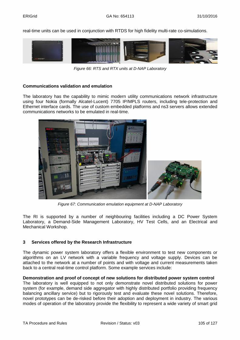
ERIGrid GA No: 654113 31/10/2016
TA Procedure and Rules Revision / Status: v03 105 of 127
real-time units can be used in conjunction with RTDS for high fidelity multi-rate co-simulations.
Figure 66: RTS and RTX units at D-NAP Laboratory
Communications validation and emulation
The laboratory has the capability to mimic modern utility communications network infrastructure using four Nokia (formally Alcatel-Lucent) 7705 IP/MPLS routers, including tele-protection and Ethernet interface cards. The use of custom embedded platforms and ns3 servers allows extended communications networks to be emulated in real-time.
Figure 67: Communication emulation equipment at D-NAP Laboratory
The RI is supported by a number of neighbouring facilities including a DC Power System Laboratory, a Demand-Side Management Laboratory, HV Test Cells, and an Electrical and Mechanical Workshop.
3 Services offered by the Research Infrastructure
The dynamic power system laboratory offers a flexible environment to test new components or algorithms on an LV network with a variable frequency and voltage supply. Devices can be attached to the network at a number of points and with voltage and current measurements taken back to a central real-time control platform. Some example services include:
Demonstration and proof of concept of new solutions for distributed power system control The laboratory is well equipped to not only demonstrate novel distributed solutions for power system (for example, demand side aggregator with highly distributed portfolio providing frequency balancing ancillary service) but to rigorously test and evaluate these novel solutions. Therefore, novel prototypes can be de-risked before their adoption and deployment in industry. The various modes of operation of the laboratory provide the flexibility to represent a wide variety of smart grid

ERIGrid GA No: 654113 31/10/2016
TA Procedure and Rules Revision / Status: v03 106 of 127
configurations and scenarios. Hardware in the loop testing of control, protection, and automation equipment Using hardware in the loop testing, all primary power system equipment and assets are simulated, in real-time. It is possible to simulate arbitrary electrical networks and all the extremes of operation, including stable conditions and many different fault scenarios, such as systematically testing a range of different fault locations. However, the simulation is linked to the real commercial hardware devices under test, such as protection relays, PMUs, and communications equipment. The response of the hardware can be monitored and thereby validated. In this way, new schemes can be validated, adaptive features thoroughly tested, and new settings or operating guides resolved. Novel inverter control testing The three-phase programmable back-to-back converters allow novel inverter controls to be tested and validated in realistic conditions. For example, a 10 kW programmable DC power supply can be used to emulate a solar PV array as the input to an inverter. The inverter under test can then be subjected to different load and fault conditions while measuring its outputs, including harmonics. As part of a technological university and a strong research centre, the RI benefits from the close proximity to a large number of expert researchers in electrical technologies, modelling, simulation, and experimental validation. 4 Brief description of the organization managing the Research Infrastructure The Institute for Energy and Environment (InstEE) represents one of Europe’s largest power systems and energy technology university research groups. Comprising 32 members of academic staff, over 200 research staff and students, and 18 technical and administrative colleagues, the Institute has four main research groups: Advanced Electrical Systems, High Voltage Technology, Power Electronics Drives and Energy Conversion, Wind Energy and Control. This is complemented by the Power Networks Demonstration Centre (PNDC) which hosts a fully operational HV and LV demonstration network and dedicated team of research, technical and support staff. PNDC accelerates grid-ready validation at a larger scale and higher voltage level than is possible than at the D-NAP facility.
Figure 68: D-NAP facility
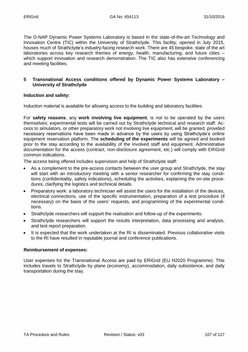
ERIGrid GA No: 654113 31/10/2016
TA Procedure and Rules Revision / Status: v03 107 of 127
The D-NAP Dynamic Power Systems Laboratory is based in the state-of-the-art Technology and Innovation Centre (TIC) within the University of Strathclyde. This facility, opened in July 2015, houses much of Strathclyde’s industry-facing research work. There are 45 bespoke, state of the art laboratories across key research themes of energy, health, manufacturing, and future cities – which support innovation and research demonstration. The TIC also has extensive conferencing and meeting facilities. 5 Transnational Access conditions offered by Dynamic Power Systems Laboratory –
University of Strathclyde Induction and safety: Induction material is available for allowing access to the building and laboratory facilities.
For safety reasons, any work involving live equipment, is not to be operated by the users themselves; experimental tests will be carried out by Strathclyde technical and research staff. Ac-cess to simulators, or other preparatory work not involving live equipment, will be granted, provided necessary reservations have been made in advance by the users by using Strathclyde’s online equipment reservation platform. The scheduling of the experiments will be agreed and booked prior to the stay according to the availability of the involved staff and equipment. Administrative documentation for the access (contract, non-disclosure agreement, etc.) will comply with ERIGrid common indications.
The access being offered includes supervision and help of Strathclyde staff:
As a complement to the pre-access contacts between the user group and Strathclyde, the stay will start with an introductory meeting with a senior researcher for confirming the stay condi-tions (confidentiality, safety indications), scheduling the activities, explaining the on-site proce-dures, clarifying the logistics and technical details.
Preparatory work: a laboratory technician will assist the users for the installation of the devices, electrical connections, use of the specific instrumentation, preparation of a test procedure (if necessary) on the basis of the users’ requests, and programming of the experimental condi-tions.
Strathclyde researchers will support the realisation and follow-up of the experiments.
Strathclyde researchers will support the results interpretation, data processing and analysis, and test report preparation.
It is expected that the work undertaken at the RI is disseminated. Previous collaborative visits to the RI have resulted in reputable journal and conference publications.
Reimbursement of expenses: User expenses for the Transnational Access are paid by ERIGrid (EU H2020 Programme). This includes travels to Strathclyde by plane (economy), accommodation, daily subsistence, and daily transportation during the stay.
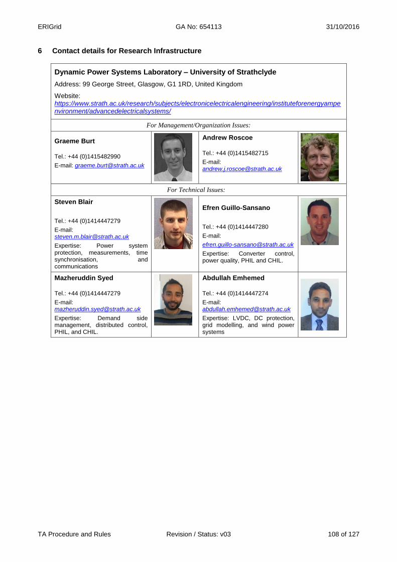
ERIGrid GA No: 654113 31/10/2016
TA Procedure and Rules Revision / Status: v03 108 of 127
6 Contact details for Research Infrastructure
Dynamic Power Systems Laboratory – University of Strathclyde
Address: 99 George Street, Glasgow, G1 1RD, United Kingdom
Website: https://www.strath.ac.uk/research/subjects/electronicelectricalengineering/instituteforenergyampenvironment/advancedelectricalsystems/
For Management/Organization Issues:
Graeme Burt
Tel.: +44 (0)1415482990
E-mail: [email protected]
Andrew Roscoe
Tel.: +44 (0)1415482715
E-mail: [email protected]
For Technical Issues:
Steven Blair
Tel.: +44 (0)1414447279
E-mail: [email protected]
Expertise: Power system protection, measurements, time synchronisation, and communications
Efren Guillo-Sansano
Tel.: +44 (0)1414447280
E-mail:
Expertise: Converter control, power quality, PHIL and CHIL.
Mazheruddin Syed
Tel.: +44 (0)1414447279
E-mail: [email protected]
Expertise: Demand side management, distributed control, PHIL, and CHIL.
Abdullah Emhemed
Tel.: +44 (0)1414447274
E-mail: [email protected]
Expertise: LVDC, DC protection, grid modelling, and wind power systems

ERIGrid GA No: 654113 31/10/2016
TA Procedure and Rules Revision / Status: v03 109 of 127
Power Networks Demonstration Centre
1 Research Infrastructure
Name of Infrastructure/Installation Power Networks Demonstration Centre (PNDC)
Location Glasgow, United Kingdom
Web Site http://pndc.co.uk/
2 Description of the Research Infrastructure The demonstration network provides a flexible ar-rangement of the primary and secondary equipment that is required to represent typical rural, urban and suburban networks in the UK (11 kV and 400 V). The network can be supplied either directly from the grid or using a 5 MVA motor-generator set to allow both voltage and frequency variances to be evaluat-ed. The network itself is built using a mixture of cables and overhead sections. Variable lumped impedance equivalents are used to provide a more dispersed network – within the footprint available. A primary substation replica allows for voltage control via on-load tap changers and automated ring main units; these are used throughout the network. The network has fibre-optic communications throughout, as well as easily accessible connection points to allow quick changeover between communications systems. The capability to apply resistive balanced and un-balanced faults at both voltage levels is also pre-sent.
Figure 69: PNDC facility (Glasgow, United Kingdom)
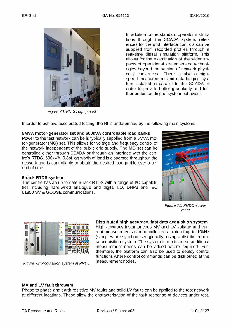
ERIGrid GA No: 654113 31/10/2016
TA Procedure and Rules Revision / Status: v03 110 of 127
Figure 70: PNDC equipment
In addition to the standard operator instruc-tions through the SCADA system, refer-ences for the grid interface controls can be supplied from recorded profiles through a real-time digital simulation platform. This allows for the examination of the wider im-pacts of operational strategies and technol-ogies beyond the section of network physi-cally constructed. There is also a high-speed measurement and data-logging sys-tem installed in parallel to the SCADA in order to provide better granularity and fur-ther understanding of system behaviour.
In order to achieve accelerated testing, the RI is underpinned by the following main systems: 5MVA motor-generator set and 600kVA controllable load banks Power to the test network can be is typically supplied from a 5MVA mo-tor-generator (MG) set. This allows for voltage and frequency control of the network independent of the public grid supply. The MG set can be controlled either through SCADA or through an interface with the cen-tre’s RTDS. 600kVA, 0.8pf lag worth of load is dispersed throughout the network and is controllable to obtain the desired load profile over a pe-riod of time. 6-rack RTDS system The centre has an up to date 6-rack RTDS with a range of I/O capabili-ties including hard-wired analogue and digital I/O, DNP3 and IEC 61850 SV & GOOSE communications.
Figure 71: PNDC equip-ment
Figure 72: Acquisition system at PNDC
Distributed high accuracy, fast data acquisition system High accuracy instantaneous MV and LV voltage and cur-rent measurements can be collected at rate of up to 10kHz (samples are synchronised globally) using a distributed da-ta acquisition system. The system is modular, so additional measurement nodes can be added where required. Fur-thermore, the platform can also be used to deploy control functions where control commands can be distributed at the measurement nodes.
MV and LV fault throwers Phase to phase and earth resistive MV faults and solid LV faults can be applied to the test network at different locations. These allow the characterisation of the fault response of devices under test.

ERIGrid GA No: 654113 31/10/2016
TA Procedure and Rules Revision / Status: v03 111 of 127
This capability addresses the issue of having to wait for real faults to occur during a field trial of a piece of equipment connected to a real network. 3 Services offered by the Research Infrastructure Grid integration, characterisation and functional testing of smart grid components and sys-tems Rigorous functional and performance testing of systems and components connected to MV or LV can be achieved. These undergo a test regime that is agreed beforehand with the user. The test network offers flexibility in the test conditions in terms of currents, voltages, frequency and network topology. SCADA integration can also be achieved over a wide range of industry standard commu-nication protocols. Hardware in the loop testing of control, protection and automation equipment Equipment that is not network ready can be tested using the RTDS in a Hardware-in-the-Loop con-figuration. The RTDS can also be interfaced to a system under test that is partially connected to the test network. The RTDS offers a rich library of power system and control components. Inverters characterisation and testing This utilises 10kW programmable DC power supplies with solar array simulation. The inverters can then be subjected to different load and fault conditions while measuring their outputs including harmonics. Testing of sensors MV and LV sensors can be subjected to realistic operating conditions, both steady state and tran-sient. Outputs of the sensors can be integrated through the PNDC SCADA infrastructure and/or the distributed data acquisition system.
Figure 73: PNDC facility (Glasgow, United Kingdom)

ERIGrid GA No: 654113 31/10/2016
TA Procedure and Rules Revision / Status: v03 112 of 127
4 Brief description of the organization managing the Research Infrastructure The Institute for Energy and Environment (InstEE) represents one of Europe’s largest power sys-tems and energy technology university research groups, comprising 32 members of academic staff, over 200 research staff and students, and 18 technical and administrative colleagues. The PNDC complements the InstEE D-NAP Dynamic Power Systems Laboratory. The PNDC focuses on mid-TRL testing and innovation projects in partnership with industry. 5 Transnational Access conditions offered by PNDC Induction and safety: The users will be inducted to the facility and a risk assessment of the work is expected to be in place at least two weeks prior to the commencement of work.
For safety reasons, any work involving live equipment, is not to be operated by the users themselves; experimental tests will be carried out by PNDC technical and research staff. Access to simulators, or other preparatory work not involving live equipment, will be granted, provided neces-sary reservations have been made in advance by the users by consulting with the PNDC project lead. The scheduling of the experiments will be agreed and booked prior to the stay according to the availability of the involved staff and equipment. Administrative documentation for the access (contract, non-disclosure agreement, etc.) will comply with ERIGrid common indications.
The access being offered includes supervision and help of PNDC staff:
As a complement to the pre-access contacts between the user group and PNDC, the stay will start with an introductory meeting with a senior researcher for confirming the stay conditions (confidentiality, safety indications), scheduling the activities, explaining the on-site procedures, clarifying the logistics and technical details.
Preparatory work: a laboratory technician will assist the users for the installation of the devices, electrical connections, use of the specific instrumentation, preparation of a test procedure (if necessary) on the basis of the users’ requests, and programming of the experimental condi-tions.
PNDC researchers will support the realisation and follow-up of the experiments.
PNDC researchers will support the results interpretation, data processing and analysis, and test report preparation.
It is expected that the work undertaken at the RI is disseminated. Previous collaborative visits to the RI have resulted in reputable journal and conference publications.
Reimbursement of expenses: User expenses for the Transnational Access are paid by ERIGrid (EU H2020 Programme). This includes travels to PNDC by plane (economy), accommodation, daily subsistence, and daily trans-portation during the stay.

ERIGrid GA No: 654113 31/10/2016
TA Procedure and Rules Revision / Status: v03 113 of 127
6 Contact details for Research Infrastructure
Power Networks Demonstration Centre (PNDC) – University of Strathclyde
Address: 62 Napier Road, Wardpark, Cumbernauld, G68 0EF, United Kingdom
Website: http://pndc.co.uk/
For Management/Organization Issues: For Technical issues:
Federico Coffele
Tel.: +44 1236617162
E-mail: [email protected]
Ibrahim Abdulhadi
Tel.: +44 1236617176
E-mail: [email protected]
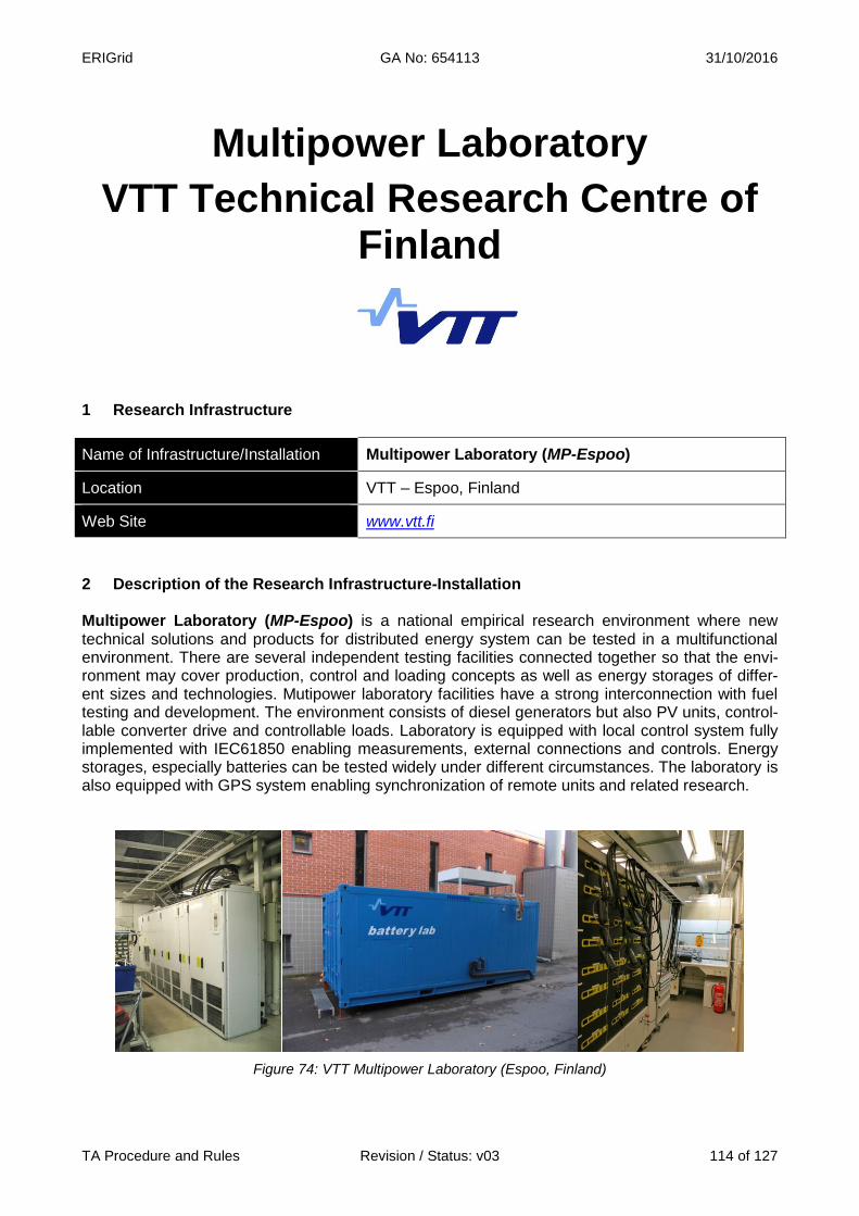
ERIGrid GA No: 654113 31/10/2016
TA Procedure and Rules Revision / Status: v03 114 of 127
Multipower Laboratory
VTT Technical Research Centre of Finland
1 Research Infrastructure
Name of Infrastructure/Installation Multipower Laboratory (MP-Espoo)
Location VTT – Espoo, Finland
Web Site www.vtt.fi
2 Description of the Research Infrastructure-Installation Multipower Laboratory (MP-Espoo) is a national empirical research environment where new technical solutions and products for distributed energy system can be tested in a multifunctional environment. There are several independent testing facilities connected together so that the envi-ronment may cover production, control and loading concepts as well as energy storages of differ-ent sizes and technologies. Mutipower laboratory facilities have a strong interconnection with fuel testing and development. The environment consists of diesel generators but also PV units, control-lable converter drive and controllable loads. Laboratory is equipped with local control system fully implemented with IEC61850 enabling measurements, external connections and controls. Energy storages, especially batteries can be tested widely under different circumstances. The laboratory is also equipped with GPS system enabling synchronization of remote units and related research.
Figure 74: VTT Multipower Laboratory (Espoo, Finland)

ERIGrid GA No: 654113 31/10/2016
TA Procedure and Rules Revision / Status: v03 115 of 127
There are some specific operation areas that may be interesting for user groups:
IEC61850 – related testing: The laboratory is equipped with latest IEDs from ABB, includ-ing a substation automation system based on ABB COM600 substation computer. This combination offers an environment where for instance protection or control solutions based on IEC61850 and for instance GOOSE messaging can be tested. The laboratory is also equipped with GPS system, enabling time synchronization and for instance wide area moni-toring/protection type applications.
Communication testing: The laboratory is currently developed to enable testing with 5G communication. The area on which the laboratory is located is among first 5G pilots. VTT is closely involved in the 5G development and looking to integrate MultiPower laboratory in 5G pilot area.
Figure 75: Communication testing architecture at Multipower Laboratory
Battery testing: the laboratory offers good possibilities for testing batteries, ranging from cell level to complete systems. There are climate chambers which can be used. Lifetime testing can be done with flexible testing arrangement. For EV battery purposes, recorded drive cycles can be used to perform tests emulating real driving conditions.
3 Services offered by the Research Infrastructure-Installation MultiPower offers testing possibilities which cover development, operational acceptance and com-mon tests for the DG products and systems. The platform is flexible and can be adapted for vari-ous purposes. Typical testing assignments and possibilities consider:
DER generation units, fuel optimisation, network interconnection issues with protection and inverter systems
ICT applications for DER systems, as well as operational optimization
IEC61850-based distribution automation and devices
Different malfunctions and faults can be freely realized in the network, and behaviour of the generation, protection and control systems can be identified in actual environment
ERIGrid GA No: 654113 31/10/2016
TA Procedure and Rules Revision / Status: v03 116 of 127
Possibility of emulating wind generator with converter drive
Testing of EV battery packs, modules and cells 4 Brief description of the organization managing the Research Infrastructure VTT Technical Research Centre of Finland is a non-profit government organisation established by law and operating under the auspices of the Finnish Ministry of Employment and the Economy. VTT is a multitechnological research organisation providing high-end technology solutions and in-novation services. VTT has a staff of 2600. Through its international scientific and technology net-works, VTT can produce information, upgrade technology knowledge, and create business intelli-gence and value added for its stakeholders. VTT’s activities are focused on three areas: Knowledge intensive products and services, Smart industry and energy systems and Solutions for natural resources and environment. VTT has 70 years of experience in addressing the needs of industry and the knowledge-based society. In the past 20 years, VTT has participated in more than 1000 European R&D Framework Programme projects, within various thematic programmes. VTT has been granted ISO 9001:2000 certificate and ISO 14001 environmental certificate. Research area “Smart Energy and System Integration” conducts wide research on future energy systems and their integration. We apply a holistic view on different energy carriers and integrate strongly ICT and communication aspect with power system research. VTT is closely involved in international co-operation networks (for instance EERA, DERlab, IEA ISGAN) as well as European research projects (for instance ELECTRA, SmartNet, STORY). VTT also participates in multiple national research programs on the area of smart grids. 5 Transnational Access conditions offered by VTT The experimental system described is located at Espoo, Finland.
For safety reasons, for critical applications, the users are not expected to operate the systems by themselves; even when safety instructions will be provided, tests will be carried out by staff of VTT. For the rest of applications and after ad-hoc training, the user group will have access to the related facilities for the duration of the stay (with the support of VTT’s researchers and laboratory technicians when necessary). The scheduling of the experiments will be agreed and booked pri-or to the stay according to the availability of the involved staff and equipment. Administrative doc-umentation for the access (contract, non-disclosure agreement, etc.) will comply with ERIGrid common indications. In addition to the general corporate services (Internet connection, working space, etc.) and the support and advice on accommodation and transportation to VTT’s infrastructure, the access being offered includes supervision and help of VTT’s staff:
As a complement to the pre-access contacts between the user group and VTT, the stay will start with an introductory meeting for confirming the stay conditions (confidentiality, safety indi-cations), scheduling the activities, explaining the on-site procedures, clarifying the logistics and technical details.
Preparatory work: VTT’s staff will assist the users for the installation of the devices, electrical connections, use of the specific instrumentation, preparation of a test procedure (if necessary) on the basis of the users requests, and programming of the experimental conditions.
VTT’s researchers will support the realisation and follow-up of the experiments.
VTT’s researchers will support the results interpretation and data processing and analysis
In principle, a typical stay of 2-4 weeks is foreseen for a single user group but this period could be
ERIGrid GA No: 654113 31/10/2016
TA Procedure and Rules Revision / Status: v03 117 of 127
extended depending on the concrete user project. The user group can use the infrastructure for the defined time. Access to VTT premises requires a personal security clearance procedure, conducted before arri-val by local authorities. Without the clearance the users are not allowed to move alone at VTT’s premises nor given any access rights. Reimbursement of expenses: User expenses for the Transnational Access are paid by ERIGrid (EU H2020 Programme). This includes travels to Espoo by plane, accommodation, daily subsistence, and daily transportation during the stay. For the user projects, VTT will refund the stay expenses when the stay is finished: the user must declare the incurred expenses and present the invoices/receipts to VTT in order to get the refund. Logical expenses must be made by the user: travels will be made in economy class and conven-tional hotels or equivalent accommodation will be used. These costs (travel, accommodation) will be covered and additionally a daily allowance of 40€/day can be reimbursed, following the Finnish practices. All reimbursement practices must be checked and agreed on between the user and VTT prior to making any reservations for travelling. VTT will primarily reimburse the costs to organization (company, university, etc.). Please note that reimbursement of daily allowances to individual person can lead to taxation depending on practic-es. 6 Contact details for Research Infrastructure
VTT Technical Research Centre of Finland
Address: Vuorimiehentie 3, 02150 Espoo, Finland
Website: www.vtt.fi
For Management/Organization Issues: For Technical issues:
Kari Mäki
Tel.: +358 40 142 9785
E-mail: [email protected]
Riku Pasonen
Tel.: + 358 40 574 8105
E-mail: [email protected]
ERIGrid GA No: 654113 31/10/2016
TA Procedure and Rules Revision / Status: v03 118 of 127
Oulu Smart Grid Laboratory
VTT Technical Research Centre of Finland
1 Research Infrastructure
Name of Infrastructure/Installation Oulu Smart Grid Laboratory (SG-Oulu)
Location VTT – Oulu, Finland
Web Site www.vtt.fi
2 Description of the Research Infrastructure-Installation Oulu Smart Grid laboratory (SG-Oulu) VTT has new Smart Grid laboratory for customer-level research. This facility consists of PV panels and inverter equipment, wind power unit, storages and EV with charging post. At the same, the la-boratory is built as a home environment where household devices can be monitored and controlled intelligently. Key technical features include:
Wind mill 5,5 kW installed on top of roof
Solar energy 7.2 kW
Mini inverter and two rotating solar panels (250 W, 240)
Inverter 400V ~3 phase 15 kW
Energy storage 58 kWh
EV (Peugeot ION) and charging posts (2) with remote control
Controllable domestic loads The laboratory has flexible controllability possibilities:
Network and consumption control
HTML5 & CSS3 based control interface
Programmable user interface for monitoring, control and decision making
System details from power source, consumption, energy storage etc.
Decision making tools for selling/buying energy and managing energy consumption
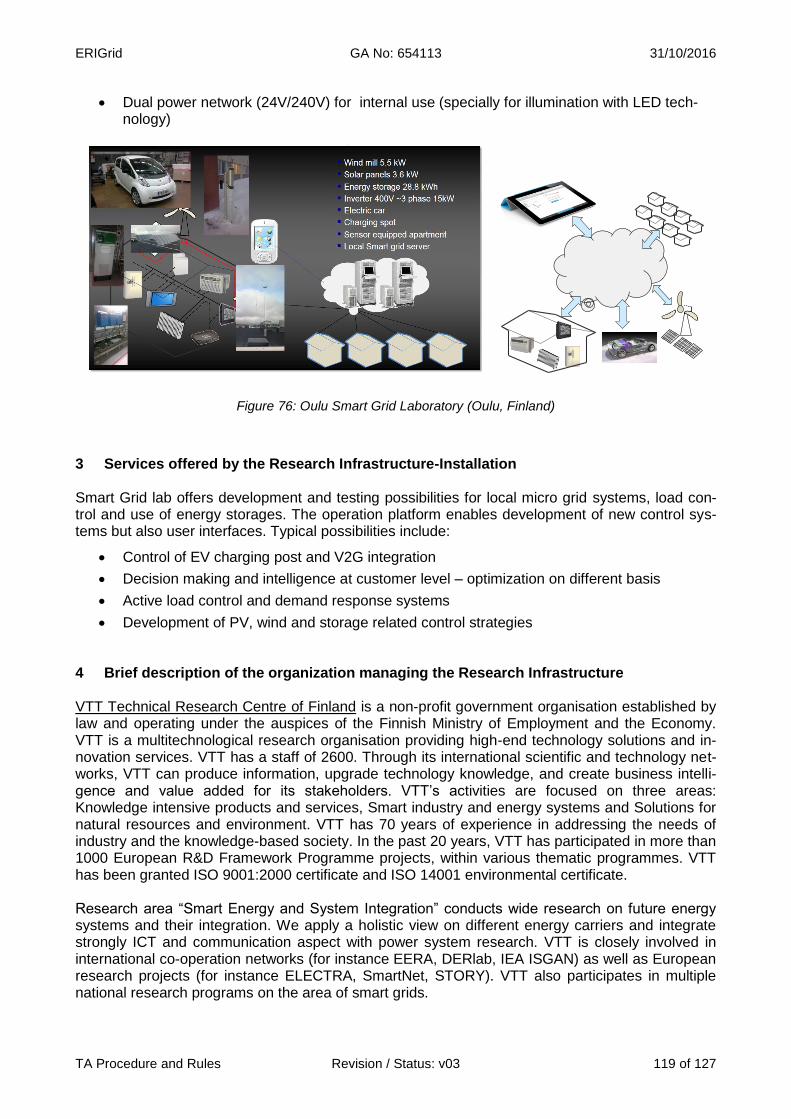
ERIGrid GA No: 654113 31/10/2016
TA Procedure and Rules Revision / Status: v03 119 of 127
Dual power network (24V/240V) for internal use (specially for illumination with LED tech-nology)
Figure 76: Oulu Smart Grid Laboratory (Oulu, Finland)
3 Services offered by the Research Infrastructure-Installation Smart Grid lab offers development and testing possibilities for local micro grid systems, load con-trol and use of energy storages. The operation platform enables development of new control sys-tems but also user interfaces. Typical possibilities include:
Control of EV charging post and V2G integration
Decision making and intelligence at customer level – optimization on different basis
Active load control and demand response systems
Development of PV, wind and storage related control strategies 4 Brief description of the organization managing the Research Infrastructure VTT Technical Research Centre of Finland is a non-profit government organisation established by law and operating under the auspices of the Finnish Ministry of Employment and the Economy. VTT is a multitechnological research organisation providing high-end technology solutions and in-novation services. VTT has a staff of 2600. Through its international scientific and technology net-works, VTT can produce information, upgrade technology knowledge, and create business intelli-gence and value added for its stakeholders. VTT’s activities are focused on three areas: Knowledge intensive products and services, Smart industry and energy systems and Solutions for natural resources and environment. VTT has 70 years of experience in addressing the needs of industry and the knowledge-based society. In the past 20 years, VTT has participated in more than 1000 European R&D Framework Programme projects, within various thematic programmes. VTT has been granted ISO 9001:2000 certificate and ISO 14001 environmental certificate. Research area “Smart Energy and System Integration” conducts wide research on future energy systems and their integration. We apply a holistic view on different energy carriers and integrate strongly ICT and communication aspect with power system research. VTT is closely involved in international co-operation networks (for instance EERA, DERlab, IEA ISGAN) as well as European research projects (for instance ELECTRA, SmartNet, STORY). VTT also participates in multiple national research programs on the area of smart grids.

ERIGrid GA No: 654113 31/10/2016
TA Procedure and Rules Revision / Status: v03 120 of 127
5 Transnational Access conditions offered by VTT The experimental system described is located at Oulu, Finland.
For safety reasons, for critical applications, the users are not expected to operate the systems by themselves; even when safety instructions will be provided, tests will be carried out by staff of VTT. For the rest of applications and after ad-hoc training, the user group will have access to the related facilities for the duration of the stay (with the support of VTT’s researchers and laboratory technicians when necessary). The scheduling of the experiments will be agreed and booked pri-or to the stay according to the availability of the involved staff and equipment. Administrative doc-umentation for the access (contract, non-disclosure agreement, etc.) will comply with ERIGrid common indications.
In addition to the general corporate services (Internet connection, working space, etc.) and the support and advice on accommodation and transportation to VTT’s infrastructure, the access being offered includes supervision and help of VTT’s staff:
As a complement to the pre-access contacts between the user group and VTT, the stay will start with an introductory meeting for confirming the stay conditions (confidentiality, safety indi-cations), scheduling the activities, explaining the on-site procedures, clarifying the logistics and technical details.
Preparatory work: VTT’s staff will assist the users for the installation of the devices, electrical connections, use of the specific instrumentation, preparation of a test procedure (if necessary) on the basis of the users requests, and programming of the experimental conditions.
VTT’s researchers will support the realisation and follow-up of the experiments.
VTT’s researchers will support the results interpretation and data processing and analysis
In principle, a typical stay of 2-4 weeks is foreseen for a single user group but this period could be extended depending on the concrete user project. The user group can use the infrastructure for the defined time. Access to VTT premises requires a personal security clearance procedure, conducted before arri-val by local authorities. Without the clearance the users are not allowed to move alone at VTT’s premises nor given any access rights. Reimbursement of expenses: User expenses for the Transnational Access are paid by ERIGrid (EU H2020 Programme). This includes travels to Oulu by plane, accommodation, daily subsistence, and daily transportation dur-ing the stay. For the user projects, VTT will refund the stay expenses when the stay is finished: the user must declare the incurred expenses and present the invoices/receipts to VTT in order to get the refund. Logical expenses must be made by the user: travels will be made in economy class and conven-tional hotels or equivalent accommodation will be used. These costs (travel, accommodation) will be covered and additionally a daily allowance of 40€/day can be reimbursed, following the Finnish practices. All reimbursement practices must be checked and agreed on between the user and VTT prior to making any reservations for travelling.

ERIGrid GA No: 654113 31/10/2016
TA Procedure and Rules Revision / Status: v03 121 of 127
VTT will primarily reimburse the costs to organization (company, university, etc.). Please note that reimbursement of daily allowances to individual person can lead to taxation depending on practic-es. 6 Contact details for Research Infrastructure
VTT Technical Research Centre of Finland
Address: Vuorimiehentie 3, 02150 Espoo, Finland
Website: www.vtt.fi
For Management/Organization Issues: For Technical issues:
Kari Mäki
Tel.: +358 40 142 9785
E-mail: [email protected]
Riku Pasonen
Tel.: + 358 40 574 8105
E-mail: [email protected]
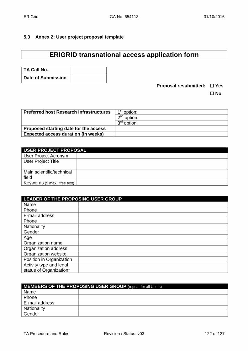
ERIGrid GA No: 654113 31/10/2016
TA Procedure and Rules Revision / Status: v03 122 of 127
5.3 Annex 2: User project proposal template
ERIGRID transnational access application form
TA Call No.
Date of Submission
Proposal resubmitted: Yes
No
Preferred host Research Infrastructures 1st option:
2nd option:
3rd option:
Proposed starting date for the access
Expected access duration (in weeks)
USER PROJECT PROPOSAL
User Project Acronym
User Project Title
Main scientific/technical field
Keywords (5 max., free text)
LEADER OF THE PROPOSING USER GROUP
Name
Phone
E-mail address
Phone
Nationality
Gender
Age
Organization name
Organization address
Organization website
Position in Organization
Activity type and legal status of Organization1
MEMBERS OF THE PROPOSING USER GROUP (repeat for all Users)
Name
Phone
E-mail address
Nationality
Gender

ERIGrid GA No: 654113 31/10/2016
TA Procedure and Rules Revision / Status: v03 123 of 127
Age
Organization name
Organization address
Organization website
Position in Organization
Activity type and legal status of Organization1
SUMMARY OF PROPOSED RESEARCH (about 1/2 page) [Prepare a ½ page summary describing the relevance, scope and objectives of the proposed work, and the expected outcomes.]
STATE-OF-THE-ART (about 1 ½ page) [Describe in brief (about 1½ page) the current knowledge on the subject, citing recent relevant references. Identify any knowledge gaps and their relevance.]
References [List relevant references.]
DETAILED DESCRIPTION OF PROPOSED PROJECT: OBJECTIVES, EXPECTED OUTCOMES, FUNDAMENTAL SCIENTIFIC/TECHNICAL VALUE (2-3 pages) [Provide a detailed description of the objectives of the proposed activity, the way these objectives will be fulfilled through the proposed work, as well as indications on the expected outcomes and the fundamental scientific and technical value and interest of the proposal. Specify the activities to be undertaken, the type of TA infrastructure needed, the foreseen test setup, number of tests, possible test sequence, and parameters to be measured and controlled. Describe any special requirements for equipment, standards, safety measures, etc. Point out any shortcomings, uncertainties and risks for the fulfillment of the project objectives, as well as the means to mitigate relevant risks.]
ORIGINALITY, INNOVATION AND IMPACT OF PROPOSED RESEARCH (1-2 pages) [Demonstrate the originality and innovation of the proposed work and the impact the expected results will have on current and future research or practice, public safety, European standardization, competitiveness, integration and cohesion and on sustainable growth.]
SYNERGY WITH ONGOING RESEARCH (about ½ page) [Provide information on any concurrent research project with the same or similar subject with the one proposed. Describe the synergy (if any) that will be sought between the existing and the proposed project. Explain the degree of alignment with the ERIGrid approach, scope and objectives]
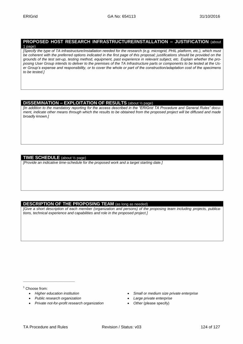
ERIGrid GA No: 654113 31/10/2016
TA Procedure and Rules Revision / Status: v03 124 of 127
PROPOSED HOST RESEARCH INFRASTRUCTURE/INSTALLATION – JUSTIFICATION (about
1 page) [Specify the type of TA infrastructure/installation needed for the research (e.g. microgrid, PHIL platform, etc.), which must be coherent with the preferred options indicated in the first page of this proposal; justifications should be provided on the grounds of the test set-up, testing method, equipment, past experience in relevant subject, etc. Explain whether the pro-posing User Group intends to deliver to the premises of the TA Infrastructure parts or components to be tested at the Us-er Group’s expense and responsibility, or to cover the whole or part of the construction/adaptation cost of the specimens to be tested.]
DISSEMINATION – EXPLOITATION OF RESULTS (about ½ page) [In addition to the mandatory reporting for the access described in the “ERIGrid TA Procedure and General Rules” docu-ment, indicate other means through which the results to be obtained from the proposed project will be diffused and made broadly known.]
TIME SCHEDULE (about ½ page) [Provide an indicative time-schedule for the proposed work and a target starting date.]
DESCRIPTION OF THE PROPOSING TEAM (as long as needed) [Give a short description of each member (organization and persons) of the proposing team including projects, publica-tions, technical experience and capabilities and role in the proposed project.]
______________________________________
1 Choose from:
Higher education institution Small or medium size private enterprise
Public research organization Large private enterprise
Private not-for-profit research organization Other (please specify)

ERIGrid GA No: 654113 31/10/2016
TA Procedure and Rules Revision / Status: v03 125 of 127
5.4 Annex 3: Template for the declaration of TA expenses by the user When the stay is completed, the TA User Group can use the following template for declaring the incurred expenses during the access. The sheet must be signed by the User Group members and the bank account details provided to get the refund. This declaration must be accompanied with a copy of the corresponding invoices and tickets (scanned file) and sent to the host infrastructure for approval and refund.
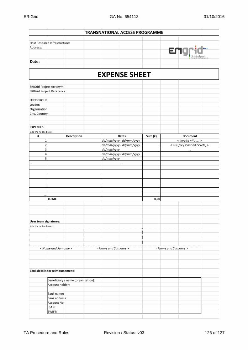
ERIGrid GA No: 654113 31/10/2016
TA Procedure and Rules Revision / Status: v03 126 of 127
Host Research Infrastructure:
Address:
Date:
ERIGrid Project Acronym:
ERIGrid Project Reference:
USER GROUP
Leader:
Organization:
City, Country:
EXPENSES:
(add the nedeed rows)
# Sum (€)
1
2
3
4
5
…
…
0,00
User team signatures:
(add the nedeed rows)
Bank details for reimbursement:
Beneficiary's name (organization):
Account holder:
Bank name:
Bank address:
Account No:
IBAN:
SWIFT:
dd/mm/yyyy
…
< Invoice n º ……. >
< Name and Surname > < Name and Surname > < Name and Surname >
dd/mm/yyyy - dd/mm/yyyy
dd/mm/yyyy
dd/mm/yyyy - dd/mm/yyyy
< PDF file (scanned tickets) >
…
EXPENSE SHEET
TRANSNATIONAL ACCESS PROGRAMME
TOTAL
Description Dates
dd/mm/yyyy - dd/mm/yyyy
Document
ERIGrid GA No: 654113 31/10/2016
TA Procedure and Rules Revision / Status: v03 127 of 127
5.5 Annex 4: Essential information to be included in the access Contract A Contract for the access to the Research Infrastructure between the proposing User Group and the host Research Infrastructure must be signed by both Parties before starting the stay. The final balance of “access days” and “stay days” of the User Group members will be stated in the Adden-dum-A to the Contract and signed by both Parties after the end of the access. A template of the Contract will be available containing the basic following information (the host infrastructure can in-clude additional clauses in the final version to cover additional specific aspects of the stay):
1. Identification of the Contractors: Research Infrastructure legal name, name and institution of the Leader of the User Group.
2. Identification of the representatives of the Research Infrastructure for the execution of the Contract.
3. Identification of the members of the User Group. 4. Reference to the ERIGrid project and EU funding. 5. Definitions (whenever necessary). 6. Access provisions: total number of expected “access days” per installation/infrastructure,
and total number of expected “stay days” per user (member of the User Group). 7. Travel and subsistence reimbursement conditions. 8. Safety provisions. 9. Reporting and dissemination commitments: documents to be prepared, formats and tem-
plates, time plan. 10. Liability conditions. 11. Confidentiality obligations. 12. Intellectual Property Rights issues. 13. Signatures. 14. Addendum-A.