transparent conductors: part i
TRANSCRIPT

Transparent Conductors: Part I
Prof. Tom Mason Northwestern University
Materials Science & Engineering

• Some History and
Applications • Basic requirements for TCOs • Role of Crystal Structure • Phase Diagrams • Bulk Experimental Methods:
• Synthesis • Characterization
• Defect Chemistry
~
Transparency (> 80% through visible spectrum for
typical 1 µm thin film)
Conductivity (> 103 S/cm)
An Introduction to TCOs

TCO History and Applications

“a brown/black powder” σ = 37 S/cm
F. Streintz, Ann. Phys. (Leipzig) 9, 854 (1902)
The First Transparent TCO
CdO

thermal oxidation of sputtered Cd films on glass σ =870 S/cm (106 nm thick) with orange/gold color
K. Bädeker, Ann. Phys. (Liepzig) 22, 749 (1907)
The First Thin Film TCO

Mid-20th Century Developments
• 1930s-1940s: conductive SnO2 film patents (various glass companies)
• 1951: first ITO patent (Corning) Sn-doped In2O3
• 1959: key dissertation on ZnO properties
• 1971: ZnO varistor and TCO film patents (Japan) SnO2-based windshield de-icer

Early TCO Science: In-doped ZnO
Single crystal data: E. Scharowsky, A. Physik, 135, 318 (1953) R. Arneth, PhD thesis, U. Erlangen (1959) (taken from: G. Heiland, E. Mollwo and F. Stockmann, in Solid State Physics, Vol. 8, ed. By F. Seitz and D. Turnbull, 1959)

TCO Development (1970-2000)
Source: T. Minami, MRS Bulletin, August, 2000 -data for pure and doped host oxides.

Why the Surge of Interest?
• Novel complex oxide/solid solution TCOs discovered in the 1990s
• Discovery of p-type TCO materials since the late 1990s
• Development of amorphous n-type TCOs since 2004
• Large area applications (organic LEDs, solar cells) require ITO-alternatives (chemical, electrical, cost issues)
• Development of Transparent Oxide Semiconductors (oxide-based thin film transistors-TTFTs)

• Low-emissivity windows • Transparent front
electrodes for flat-panel displays
• Transparent top electrodes for photovoltaic cells
• Defrosting windows (freezers, cockpits)
• Electrochromic mirrors and windows
• Oven window coatings • Static charge dissipation
coatings • Touch-panel controls • Electromagnetic shielding • Invisible security circuits • Organic light-emitting
diodes - R. Gordon, MRS Bulletin, August 2000.
A Wide Array of TCO Applications

Large-Area Applications • High electrical conductivity (>1000 S/cm) • High optical transparency in visible region (>80%) • Industry standards: ITO, SnO2
Ga2O3
In2O3
ZnO
CdO
SnO2
Basic TCO Requirements

Basic TCO Requirements
I. Hamberg and C. G. Grandqvist, J. Appl. Phys., 60, R123 (1986).
Eg0 > 3.1 eV
N-type Degenerate Doping
Eg > Eg0
Insulating Parent Compound
• Parent oxide with relatively wide band gap • Interband transitions > 3.1 eV (cations with filled d-shells) • Highly dispersed conduction (or valence) band (high mobility) • Ability to donor- or acceptor-dope to ~1021/cm3

TCO-Active Species: d10 Cations
Cu Zn Ga
Ag Cd In Sn
= p-type = n-type
+1 +2 +3 +4 valence state

Typical Parameters:
• Large electron populations in the 1020 to 1021 cm-3 range (highly degenerate)
• High electron mobilites in the 30-70 cm2/V-s range
• Large conductivities (in excess of 1000 S/cm) • Low absorption in the visible (α<104 cm-1)
– 100nm film 90% transparent in the visible – 500nm (0.5µm) film 60% transparent in the visible
Role of Crystal Structure

Shannon’s n-type TCO Maxim
“…continuous edge-sharing of Cd2+, In3+ and Sn4+ octahedra is a necessary criterion for the formation of an n-type transparent conductor.”
-R. D. Shannon et al., J. Phys. Chem. Solids, 38, 877 (1977).

Octahedral Cation TCO Family
CdO SnO2
rocksalt structure rutile structure
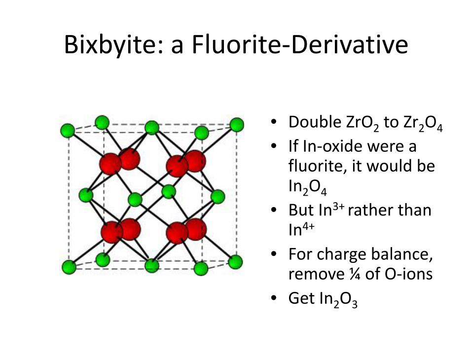
Bixbyite: a Fluorite-Derivative
• Double ZrO2 to Zr2O4
• If In-oxide were a fluorite, it would be In2O4
• But In3+ rather than In4+
• For charge balance, remove ¼ of O-ions
• Get In2O3

Octahedral Cation TCO Family
• Edge-shared octahedra • The octahedra are
distorted (hints at why amorphous TCOs also conduct)
• Can be readily doped (e.g., Sn4+) and co-doped (Zn2+/Sn4+ and Cd2+/Sn4+ )
• The basis of a rich family of complex oxide solid solutions
In2O3
bixbyite structure

Octahedral Cation TCO Family
Yellow: Tetrahedral (Td)
Blue: Octahedral (Oh)
spinel structure
• Spinel = MgAl2O4 • 1/2 octahedral
interstices occupied: octahedral sites
• 1/8 of tetrahedral interstices occupied: tetrahedral sites
• Arrays of edge-shared cation octahedra
• Spinels are well-known for exhibiting extended solid solutions

The Importance of Phase Diagrams

The Cd-In-Sn-O (CITO) System
1175°C
CdO (rocksalt) o-Cd2SnO4
(Sr2PbO4) CdSnO3
(o-Perovskite)
CdIn2O4 In2-2x(Cd,Sn)2xO3 (0 < x < 0.34)
(bixbyite)
ITO
SnO2 (rutile)
(1-x)CdIn2O4 – (x)Cd2SnO4 (0 < x < 0.75)
(spinel)
InO1.5 (bixbyite)
rutile + bixbyite
spinel + rocksalt
spinel + bixbyite
2+
3+
4+

Optimized conductivity vs. OSD
0
5
10
15
20
0 1 2 3 4 5
o-C
dSnO
3
o-C
d2Sn
O4
Cd2
SnO
4
Sn-d
oped
In2O
3
In-d
oped
CdO
σ (k
S/cm
)
oct-site density (x1022 cm-3)
SnO
2
Bellingham et al. (1991) predicted the maximum TCO conductivity = 25,000 S/cm

Shannon’s n-type TCO Maxim
“…continuous edge- or corner- sharing of Cd2+, In3+ and Sn4+ octahedra is a necessary criterion for the formation of an n-type transparent conductor.”
-R. D. Shannon et al., J. Phys. Chem. Solids, 38, 877 (1977).
What about Zn2+?

In2O3(ZnO)k
T = 1275 ˚C
Zn2SnO4
The Zn-In-Sn-O System
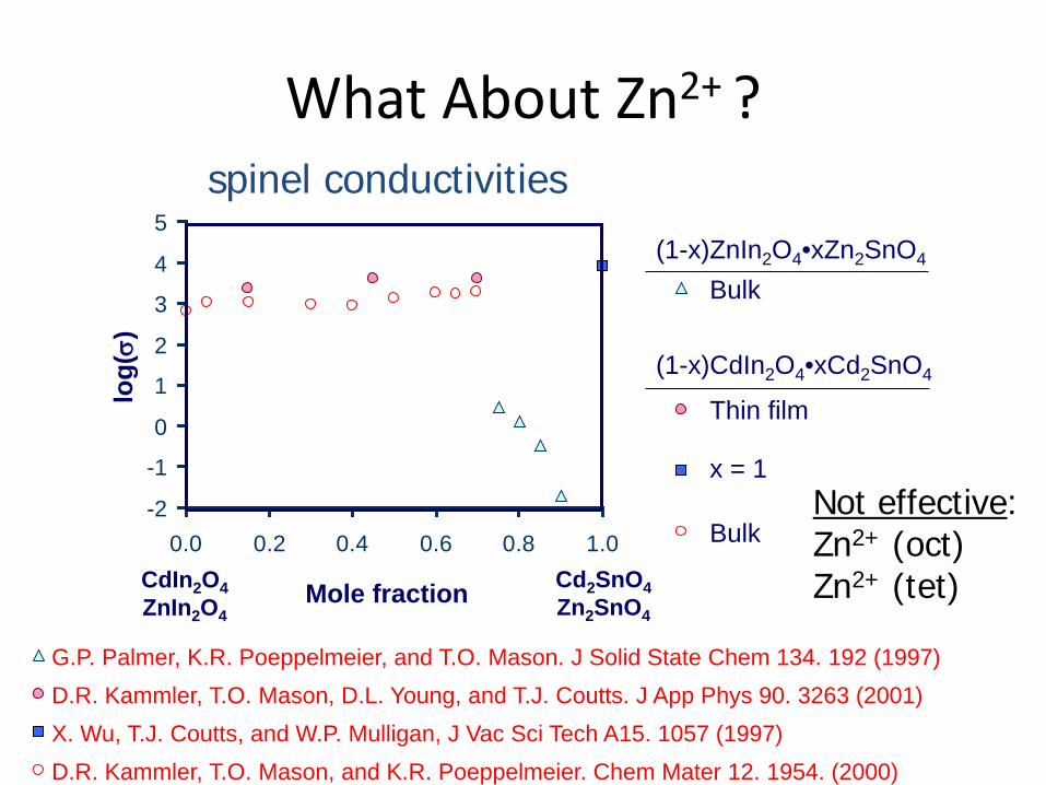
spinel conductivities lo
g(σ)
Mole fraction CdIn2O4 ZnIn2O4
Cd2SnO4 Zn2SnO4
-2
-1
0
1
2
3
4
5
0.0 0.2 0.4 0.6 0.8 1.0
G.P. Palmer, K.R. Poeppelmeier, and T.O. Mason. J Solid State Chem 134. 192 (1997) D.R. Kammler, T.O. Mason, D.L. Young, and T.J. Coutts. J App Phys 90. 3263 (2001) X. Wu, T.J. Coutts, and W.P. Mulligan, J Vac Sci Tech A15. 1057 (1997) D.R. Kammler, T.O. Mason, and K.R. Poeppelmeier. Chem Mater 12. 1954. (2000)
(1-x)ZnIn2O4•xZn2SnO4
(1-x)CdIn2O4•xCd2SnO4
Bulk
Bulk
Thin film
x = 1 Not effective: Zn2+ (oct) Zn2+ (tet)
What About Zn2+ ?

Shannon’s n-type TCO Maxim
“…continuous edge- or corner- sharing of Cd2+, In3+ and Sn4+ octahedra is a necessary criterion for the formation of an n-type transparent conductor.”
-R. D. Shannon et al., J. Phys. Chem. Solids, 38, 877 (1977).
What about ZnO?

Tetrahedral Coordination TCO
• ZnO is the only TCO with exclusively tetrahedral coordination
• In other crystal structures/CNs Zn is not as strong a contributor to TCO behavior
• Zn cations play an important role in stabilizing amorphous n-type TCOs
wurtzite structure
ZnO

Bulk Experimental Methods

• Batch calculations of precursors (usually constituent oxides) • Weighing and mixing of precursors
1. Obtain starting oxide
powders
2. Dry powders
3. Batch Calculations
4. Weigh out correct
quantities
5. Grind in acetone
Solid State Reactions

Cold pressing Hot pressing
• Al2O3 dies prevent reduction • 67 – 774 MPa max • 0.5” to 1.7” pellets
• Typically ~130 MPa with steel dies • Can add binder/ pressing aid • 0.25” to 1.5” pellets
Pellet Pressing

• Quenching preserves high temperature phase Limitation: thermal shock
• Nested crucibles minimize preferential evaporation (e.g. Zn) • Sacrificial powder minimizes contamination
• Up to ~ 1400°C • In fume hoods when needed
Time frame: 1 day – 2 weeks
Solid State Reaction/Sintering

Computer Control
Lens
Sapphire Window
Heated Substrate
Holder
Excimer Laser
λ=248nm
Vacuum Pumps
Rotated To Prevent
Localized Heating
Stepper Index
Between Targets
Reaction Gas Inlet
Multi-target Pulsed Laser Deposition (collaboration with Prof. Chang, Dr. Buchholz)

Rietveld Analysis
35
Weight Fraction of Each Phase:

Determining Phase Boundaries
36
Lever Rule: fβ = (y-z)/(x-z) Disappearing Phase Method

Phase Boundaries: Vegard's Law
37
• Lattice constant changes linearly with composition until the solubility limit is reached. • Can use Rietveld refinement with internal silicon standard to accurately measure the lattice constant.

898°C
894°C
R
R+S
S S+W
R+W
C=0.82
C=Co/(Zn+Co)
C=0.77
T
The Zinc Oxide – Cobalt Oxide System
T-X Phase Diagram in Air

4-Point Conductivity and Thermopower
39

In situ bulk electrical measurements
Conductivity vs. time for change of pO2 (from 1000ppm to 1%O2) at 750oC
Controlled atmosphere electrical measurements performed for a sample of c-ZITO (In1.2Sn0.40Zn0.40O3)

PC-controlled current source and multimeter
Gold electrodes
Sample
Alumina sample and TC holder
log pO2
controlled atmosphere tube furnace:
log pO2
p-type n-type
Slopes majority defect type
Brouwer Analysis for Determining Point Defect Mechanism

Powder-Solution-Composite Method Slurry: NaCl solution + powder sample
Stainless steel electrodes Polypropylene tube
Comparison of slurry composite conductivity to matrix (plain NaCl solution) conductivity: Cross over point corresponds to bulk value for powder in question. Use effective medium theory to fit the data.
Motivation: Measurement of low-temperature derived materials in powder form. Technique: Based on impedance spectroscopy of composite materials

AC Impedance Spectroscopy (AC-IS)
43
Apply oscillating voltage, measure current
response.
Ratio is the complex impedance, which depends on
frequency.
Nyquist plot can illustrate different processes in
frequency domain
Phase offset = θ/ω
θ

Hall Effect
44
RH = Hall coefficient Hall Mobility:

Hall Effect: 17 T and 0.58 T
45
17 T
0.58 T

Both Hall resistance and Seebeck coefficient are positive
pedBRxy +=
+
+= A
pNLn
ekQ v
46
+Ni
+Mg
Co2+xZn1-xO4
Experiment: Confirms Robust P-type Character

Diffuse Reflectance Spectroscopy
47
Sample
Detector
Integrating sphere

Diffuse Reflectance Spectroscopy
Zn-rich Rh2ZnO4

Defect Chemistry of n-type TCOs
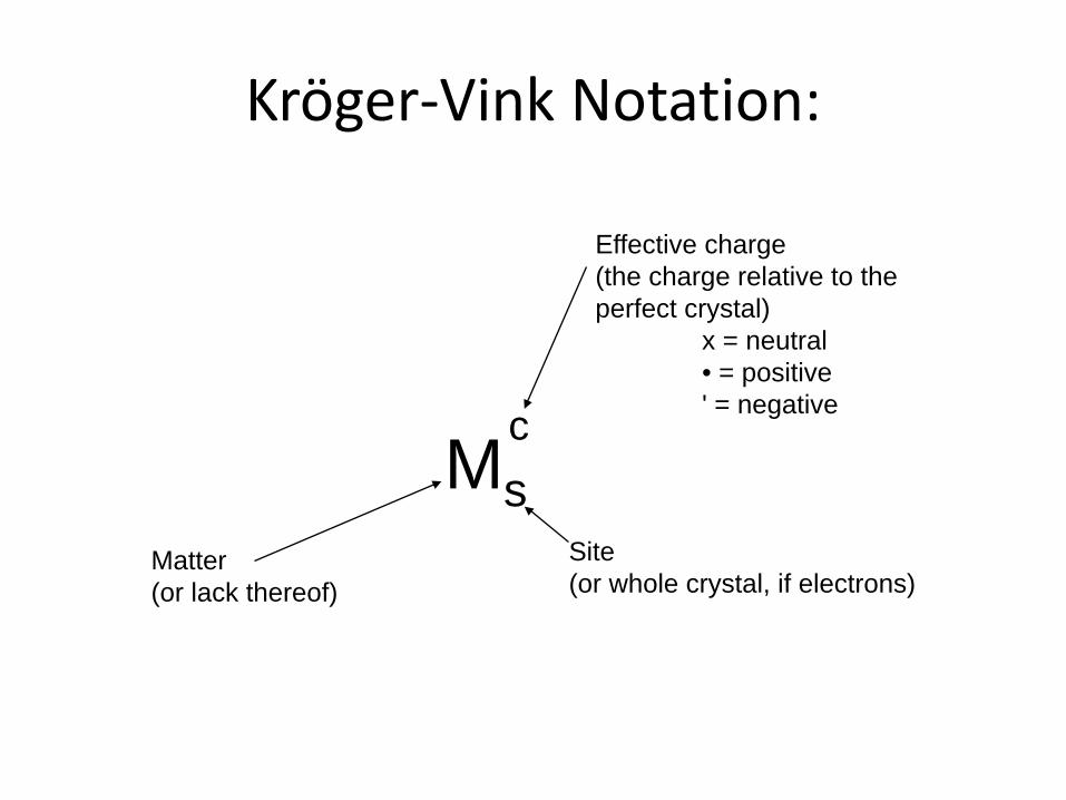
Kröger-Vink Notation:
Ms c
Matter (or lack thereof)
Site (or whole crystal, if electrons)
Effective charge (the charge relative to the perfect crystal) x = neutral • = positive ' = negative

Writing Balanced Defect Reactions:
Ms c
Mass Balance (massleft = massright)
Site Ratio (host site ratioleft = host site ratioright)
Charge Balance (chargeleft = chargeright)
Note: sites can be created or destroyed, but only in the stoichiometric ratio of the host!

An Example Point Defect Reaction
OOx ⇐⇒ 1/2O2(g) + VO
•• + 2e'
Kred pO2-1/2 = [VO
••] n2
n = 2 [VO••] or [VO
••] = n/2
n = (2Kred )1/3 pO2-1/6
ZnO

Point defects in n-type TCOs
log pO2 log [D]
n=2[VO••] n=2[VO
••] n=[D•] n=[D•]
-1/6
-1/2 -2
OOx ↔ 1/2O2(g) + VO
•• + 2e'
intrinsic extrinsic intrinsic extrinsic
Is this the whole story?

1 24
0.1
1
10
-16 -12 -8 -4 0
Po2 (atm)
Nor
mal
ized
con
duct
ivity
(σ/σ m
ax)
Norm
alized thermopow
er (Q/Q
max )
10 1010 10
81−
10
241
121
41−
0.1
1
10
-6 -4 -2 0
Po2 (atm)
Nor
mal
ized
con
duct
ivity
(σ/σ m
ax)
Norm
alized thermopow
er (Q/Q
max )
10 1010 10
81−
241
41−
121
1 12
1 12
Bulk ITO at 800oC
Nano ITO at 500oC
Q ∝ m*/n2/3; m* ∝ n1/3
Q ∝ n-1/3
Electrical Properties
1 24
24

Formation of point defect associates:
Reactiion: (2Sn•In
Oi'')x → ½ O2 (g) + 2Sn•In + 2 e'
n ∝ pO2 -1/8 Kröger-Vink Sn.
In represents a tin (on an indium site) with 1+ charge
notation Oi” represents an oxygen interstitial with 2– charge
OO represents an oxygen (on an oxygen site)
( )x represents a neutral defect
1 G Frank and H Köstlin, Appl Phys A, 27 (1982), 197
The Frank-Köstlin Cluster

ITO Defect Chemistry

• Rietveld analysis of combined neutron and X-ray diffraction patterns (bulk and nano ITO) Sn-to-oxygen interstitial ratio ~2:1
• EXAFS studies of bulk and nano ITO specimens – Sn coordination number > 6 – First near neighbor distances of Sn similar to that
in SnO2
Evidence for Defect Associates in ITO

00 )( IIxeII t ∝⇒= − µµ
Determines: Oxidation/charge state Local structure
Atomic distances Coordination numbers
Element specific Sensitive at low concentrations
X-ray Absorption Fine Structure

Defect Chemistry of n-type TCOs (Cont’d)

1175°C
CdO (rocksalt) o-Cd2SnO4
(Sr2PbO4) CdSnO3
(o-Perovskite)
CdIn2O4 In2-2x(Cd,Sn)2xO3 (0 < x < 0.34)
(bixbyite)
ITO
SnO2 (rutile)
(1-x)CdIn2O4 – (x)Cd2SnO4 (0 < x < 0.75)
(spinel)
InO1.5 (bixbyite)
rutile + bixbyite
spinel + rocksalt
spinel + bixbyite
D. R. Kammler, T. O. Maosn, K. R. Poeppelmeieir, J. Am. Ceram. Soc., 84, 1004 (2001)
The Cd-In-Sn System
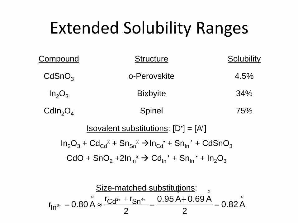
Compound Structure Solubility
CdSnO3 o-Perovskite 4.5%
In2O3 Bixbyite 34%
CdIn2O4 Spinel 75%
Isovalent substitutions: [D•] = [A′]
In2O3 + CdCdx + SnSn
x InCd• + SnIn ′ + CdSnO3
CdO + SnO2 +2InInx CdIn ′ + SnIn
• + In2O3
Size-matched substitutions:
A0.82
2A0.69A0.95
2rr
A0.80r42
3SnCd
In =+
=+
≈=++
+
Extended Solubility Ranges

[In] = 0.66
InO1.5
CdO SnO2
Tie lines connecting bixbyite & spinel phase fields
Tie lines connecting bixbyite & rutile
phase fields
Line of perfect stoichiometry In2-2xCdxSnxO3
[SnIn•] - [CdIn′] = n
Spinel
Biphasic Studies

0
1
2
0 0.1 0.2 0.3 0.40
1
2
0 0.1 0.2 0.3 0.4
log(σ S
n ric
h/σC
d ric
h)
x in In2-2x(Sn,Cd)2xO4 lo
g(σ r
educ
ed/σ
as-fi
red)
x in In2-2x(Sn,Cd)2xO4
phase field width sensitivity to reduction
Conductivity Variations

[In] = 0.66
InO1.5
CdO SnO2
Tie lines connecting bixbyite & spinel phase fields
Tie lines connecting bixbyite & rutile
phase fields
Line of perfect stoichiometry In2-2xCdxSnxO3
[SnIn•] - [CdIn′] = n
Spinel
Self-Doped Materials

self-doped TCOs
-600 1 2
Free
Ene
rgy
D/A < 1 D/A > 1
lightly co-dopedbixbyite
heavily co-dopedbixbyite
-600 1 2
Free
Ene
rgy
D/A < 1 D/A > 1
lightly co-dopedbixbyite
heavily co-dopedbixbyite
Inherent Off-Stoichiometry

In2O3(ZnO)k
T = 1275 ˚C
Zn2SnO4
The Zn-In-Sn-O System

oxygen sensitive regime n= f (Oi)= f (PO2)
exhaustion regime
(2SnIn• Oi’’)x 2SnIn
• +2e’ +1/2O2
In1.2Sn0.40Zn0.40O3
or ZITO40 co-doped In2O3
Bixbyite structure
The -1/8 slope attributable to (2SnIn
• Oi’’)x complex
In1.2Sn0.40Zn0.40O3
or ZITO40
750 °C
Log PO2
Log
σIT
O
-1/8
(2SnIn• Oi’’)x 2SnIn
• +2e’ +1/2O2
In Situ Conductivity: In1.2Zn0.4Sn0.4O3

1175°C
CdO (rocksalt) o-Cd2SnO4
(Sr2PbO4) CdSnO3
(o-Perovskite)
CdIn2O4 In2-2x(Cd,Sn)2xO3 (0 < x < 0.34)
(bixbyite)
ITO
SnO2 (rutile)
(1-x)CdIn2O4 – (x)Cd2SnO4 (0 < x < 0.75)
(spinel)
InO1.5 (bixbyite)
rutile + bixbyite
spinel + rocksalt
spinel + bixbyite
D. R. Kammler, T. O. Maosn, K. R. Poeppelmeieir, J. Am. Ceram. Soc., 84, 1004 (2001)
The Cd-In-Sn System

Evidence for D/A Excess in Spinels
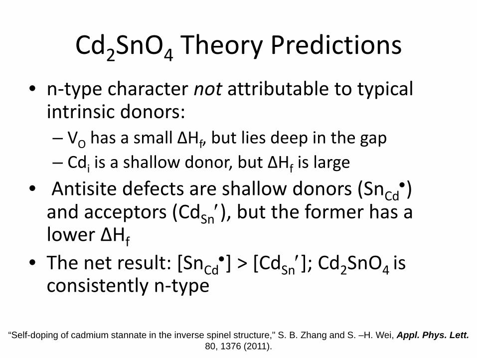
Cd2SnO4 Theory Predictions • n-type character not attributable to typical
intrinsic donors: – VO has a small ΔHf, but lies deep in the gap – Cdi is a shallow donor, but ΔHf is large
• Antisite defects are shallow donors (SnCd•)
and acceptors (CdSn′), but the former has a lower ΔHf
• The net result: [SnCd•] > [CdSn′]; Cd2SnO4 is
consistently n-type
“Self-doping of cadmium stannate in the inverse spinel structure," S. B. Zhang and S. –H. Wei, Appl. Phys. Lett. 80, 1376 (2011).

What About p-Type TCOs? Stay tuned…

Conclusions
• With the exception of ZnO, the best TCOs are high octahedral site density crystal structures
• They are n-type only • The “basis” cations are In, Sn, Zn, Cd and Ga • Their defect chemistries can be complicated
(not just oxygen vacancies) • Phase diagrams play an important role • If you can make a comparable p-type TCO…