transporter current flow diagram no. 122 / 1 2005-7.… · basic equipment cruise control system...
TRANSCRIPT

Basic equipment● Cruise control system● Multifunction display● Extended servicing intervalsfrom January 2005
Transporter Current Flow Diagram No. 122 / 1 Edition 02.2010
Notes:
For information concerning
Position of relays and fuses Multi-pin connections Control units and relays Earth connections
→ List of Fitting Locations!
For information concerning
Fault Finding Programs
→ guided fault finding
Page 1 of 27WI-XML

Transporter Current Flow Diagram No. 122 / 2
ws = whitesw = blackro = redbr = browngn = greenbl = bluegr = greyli = purplege = yellowor = orangers = pink
Onboard power supply control unit, ignition/starter switch, fusesB - StarterD - Ignition/starter switchJ519 - Onboard supply control unitSA9 - Fuse 9 on fuse holder ASB7 - Fuse 7 on fuse holder BSB16 - Fuse 16 on fuse holder BSB19 - Fuse 19 on fuse holder BSB23 - Fuse 23 on fuse holder BSB36 - Fuse 36 on fuse holder BSC17 - Fuse 17 on fuse holder CT6 - 6-pin connector, blackT6a - 6-pin connector, brownT10a - 10-pin connector, brown, coupling station on electronics box, in engine
compartmentT18a - 18-pin connector, brown
B165 - Positive connection 2 (15), in interior wiring harness
B272 - Positive connection (30), in main wiring harness
B273 - Positive connection (15), in main wiring harness
B308 - Positive connection 12 (30), in main wiring harness
B518 - Connection (86s), in main wiring harness
* - applicable from January 2006** - ⇒ Fuse concept 2 Current Flow Diagram*** - for models without day driving light only**** - applicable up to December 2005
- for models with roof console only- for models without roof console only- for models with manual gearbox and without electric interface only
Page 2 of 27WI-XML

Transporter Current Flow Diagram No. 122 / 3
ws = whitesw = blackro = redbr = browngn = greenbl = bluegr = greyli = purplege = yellowor = orangers = pink
Onboard power supply control unit, fusesA - BatteryJ519 - Onboard supply control unitSA2 - Fuse 2 on fuse holder ASB3 - Fuse 3 on fuse holder BSB31 - Fuse 31 on fuse holder BSB32 - Fuse 32 on fuse holder BSD18 - Fuse 18 on fuse holder DT5 - 5-pin connector, blackT5a - 5-pin connector, brownT6 - 6-pin connector, blackT10 - 10-pin connector, black, coupling station on electronics box, in engine
compartmentT10d - 10-pin connector, blue, coupling station on electronics box, in engine
compartmentT18 - 18-pin connector, black
636 - Earth point, onboard supply control unit
B298 - Positive connection 2 (30), in main wiring harness
B301 - Positive connection 5 (30), in main wiring harness
B302 - Positive connection 6 (30), in main wiring harness
B304 - Positive connection 8 (30), in main wiring harness
B306 - Positive connection 10 (30), in main wiring harness
* - applicable up to August 2005** - applicable from September 2005
- for models with heated rear window only
Page 3 of 27WI-XML

Transporter Current Flow Diagram No. 122 / 4
ws = whitesw = blackro = redbr = browngn = greenbl = bluegr = greyli = purplege = yellowor = orangers = pink
Onboard power supply control unit, exterior mirror heater button, heated exterior mirror, heated rear window switchE15 - Heated rear window switchE231 - Exterior mirror heater buttonJ519 - Onboard supply control unitK10 - Heated rear window warning lampL39 - Heated rear window switch illumination bulbSC20 - Fuse 20 on fuse holder CT6a - 6-pin connector, brownT6k - 6-pin connector, brown, coupling station on right of A-pillarT6l - 6-pin connector, brown, coupling station on left of A-pillarT10ad - 10-pin connector, red, coupling station on left of A-pillarT12n - 12-pin connector, brown, in driver door on exterior mirrorT12o - 12-pin connector, brown, in front passenger door on exterior mirrorT18 - 18-pin connector, blackT18a - 18-pin connector, brownZ4 - Driver side heated exterior mirrorZ5 - Front passenger side heated exterior mirror
367 - Earth connection 2, in main wiring harness
368 - Earth connection 3, in main wiring harness
369 - Earth connection 4, in main wiring harness
637 - Earth point, airbag control unit
* - ⇒ Current Flow Diagram: convenience system without window regulator- for models with heated rear window only- for models with heated exterior mirrors and without window regulator
only
Page 4 of 27WI-XML

Transporter Current Flow Diagram No. 122 / 5
ws = whitesw = blackro = redbr = browngn = greenbl = bluegr = greyli = purplege = yellowor = orangers = pink
Onboard supply control unit, heated rear window, rear window wiper motor, number plate light, high level brake light bulbJ519 - Onboard supply control unitM25 - High level brake light bulbS41 - Heated rear window fuseSB30 - Fuse 30 on fuse holder BT5a - 5-pin connector, brownT6m - 6-pin connector, red, coupling station on left of A-pillarT6o - 6-pin connector, red, coupling station on left of D-pillarT6p - 6-pin connector, brown, coupling station on left of D-pillarT10ag - 10-pin connector, brown, coupling station on left of A-pillarV12 - Rear window wiper motorX - Number plate lightZ1 - Heated rear window
35 - Earth point, under front passenger seat
219 - Earth connection 2, in rear lid wiring harness
428 - Earth connection 4, in left rear end wiring harness
653 - Earth point, left D-pillar
* - for models with rear lid only, models with wing door ⇒ Current Flow Diagram rear wing doors
** - on relay carrier (1) cockpit ⇒ Fitting Locations*** - for double cab and plank bed vehicles only**** - cross-section depends on equipment
- for models with heated rear window only- for models with high roof only
Page 5 of 27WI-XML

Transporter Current Flow Diagram No. 122 / 6
ws = whitesw = blackro = redbr = browngn = greenbl = bluegr = greyli = purplege = yellowor = orangers = pink
Onboard power supply control unit, brake light switch, reversing light switchF - Brake light switchF4 - Reversing light switchJ419 - Brake light additional relayJ519 - Onboard supply control unitJ623 - Engine control unitSB9 - Fuse 9 on fuse holder BSC35 - Fuse 35 on fuse holder CSD15 - Fuse 15 on fuse holder DT6b - 6-pin connector, redT6bz - 6-pin connector, light-pink, coupling station on electronics box, in engine
compartmentT10 - 10-pin connector, black, coupling station on electronics box, in engine
compartmentT10b - 10-pin connector, red, coupling station on electronics box, in engine
compartmentT18a - 18-pin connector, brown
B131 - Connection (54), in interior wiring harness
B520 - Connection (RL), in main wiring harness
* - only models with ESP and without serial trailer towing coupling** - only models with ESP and serial trailer towing coupling*** - for models with manual gearbox only**** - for models with automatic gearbox only
- for models with ABS and without ESP only- for models with ABS and ESP only
Page 6 of 27WI-XML
Transporter Current Flow Diagram No. 122 / 7
ws = whitesw = blackro = redbr = browngn = greenbl = bluegr = greyli = purplege = yellowor = orangers = pink
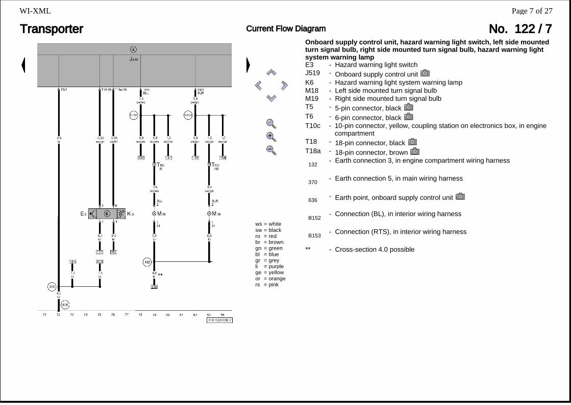
Onboard supply control unit, hazard warning light switch, left side mounted turn signal bulb, right side mounted turn signal bulb, hazard warning light system warning lampE3 - Hazard warning light switchJ519 - Onboard supply control unitK6 - Hazard warning light system warning lampM18 - Left side mounted turn signal bulbM19 - Right side mounted turn signal bulbT5 - 5-pin connector, blackT6 - 6-pin connector, blackT10c - 10-pin connector, yellow, coupling station on electronics box, in engine
compartmentT18 - 18-pin connector, blackT18a - 18-pin connector, brown
132 - Earth connection 3, in engine compartment wiring harness
370 - Earth connection 5, in main wiring harness
636 - Earth point, onboard supply control unit
B152 - Connection (BL), in interior wiring harness
B153 - Connection (RTS), in interior wiring harness
** - Cross-section 4.0 possible
Page 7 of 27WI-XML

Transporter Current Flow Diagram No. 122 / 8
ws = whitesw = blackro = redbr = browngn = greenbl = bluegr = greyli = purplege = yellowor = orangers = pink
Onboard supply control unit, X-contact relief relay, light switch, front and rear fog light switchE1 - Light switchE23 - Front and rear fog light switchJ59 - X-contact relief relayJ519 - Onboard supply control unitL9 - Light switch illumination bulbSB26 - Fuse 26 on fuse holder BT17 - 17-pin connectorT18a - 18-pin connector, brown
B138 - Positive connection (X), in interior wiring harness
B173 - Positive connection 2 (X), in interior wiring harness
B201 - Positive connection 4 (X), in interior wiring harness
* - For multivan or camper Comfortline only** - applies only to commercial vehicles or Camper/Shuttle with base level of
equipment*** - for double cab, Box-type delivery van and hybrid vehicle without
seperate vehicle interior ventilation only**** - for camper only***** - applicable from January 2006
Page 8 of 27WI-XML

Transporter Current Flow Diagram No. 122 / 9
ws = whitesw = blackro = redbr = browngn = greenbl = bluegr = greyli = purplege = yellowor = orangers = pink
Fuses, left headlight twin filament bulb, left headlight range control motor, side light bulb, front left turn signal bulbJ519 - Onboard supply control unitL1 - Left headlight twin filament bulbL22 - Left fog light bulbM1 - Left side light bulbM5 - Front left turn signal bulbSB4 - Fuse 4 on fuse holder BSB5 - Fuse 5 on fuse holder BSB6 - Fuse 6 on fuse holder BSB20 - Fuse 20 on fuse holder BT8ae - 8-pin connector, black, near headlight, front rightT10aq - 10-pin connector, black, on left of headlightT10bl - 10-pin connector, black, near front right headlightV48 - Left headlight range control motor
82 - Earth connection 1, in front left wiring harness
B144 - Positive connection (58L), in interior wiring harness
B166 - Connection (56a), in interior wiring harness
B167 - Connection (56b), in interior wiring harness
B523 - Connection (56, HRC), in main wiring harness
* - for multivan, camper Comfortline and caravelle only** - applies only to commercial vehicles, multivan classic, camper and
shuttle with base level of equipment*** - for models with front fog light only
Page 9 of 27WI-XML

Transporter Current Flow Diagram No. 122 / 10
ws = whitesw = blackro = redbr = browngn = greenbl = bluegr = greyli = purplege = yellowor = orangers = pink
Fuses, right headlight twin filament bulb, right fog light bulb, right side light bulb, front right turn signal bulbJ519 - Onboard supply control unitL2 - Right headlight twin filament bulbL23 - Right fog light bulbM3 - Right side light bulbM7 - Front right turn signal bulbSB21 - Fuse 21 on fuse holder BSB27 - Fuse 27 on fuse holder BSB28 - Fuse 28 on fuse holder BSC27 - Fuse 27 on fuse holder CT8ae - 8-pin connector, black, near headlight, front rightT10bl - 10-pin connector, black, near front right headlightT10ap - 10-pin connector, black, on right of headlight
82 - Earth connection 1, in front left wiring harness
372 - Earth connection 7, in main wiring harness
B142 - Positive connection 2 (56a), in interior wiring harness
B143 - Positive connection (58R), in interior wiring harness
B166 - Connection (56a), in interior wiring harness
B167 - Connection (56b), in interior wiring harness
B522 - Connection (FL), in main wiring harness
* - for models with front fog light only** - for models without taxi equipment only
Page 10 of 27WI-XML

Transporter Current Flow Diagram No. 122 / 11
ws = whitesw = blackro = redbr = browngn = greenbl = bluegr = greyli = purplege = yellowor = orangers = pink
Headlight range control regulator, right headlight range control motor, illumination regulators - switches and instrumentsE20 - Switches and instruments illumination regulatorE102 - Headlight range control regulatorJ519 - Onboard supply control unitL54 - Headlight range control regulator illumination bulbSB11 - Fuse 11 on fuse holder BSB35 - Fuse 35 on fuse holder BT6ac - 6-pin connectorT10ap - 10-pin connector, black, on right of headlightV49 - Right headlight range control motor
13 - Earth point, on right in engine compartment
372 - Earth connection 7, in main wiring harness
B8 - Positive connection (58), in light switch wiring harness
B340 - Connection 1 (58d), in main wiring harness
B455 - Connection (HRC), in main wiring harness
* - for models without dimming instruments illumination only** - for models with dimming instruments illumination only
- applicable up to December 2005
Page 11 of 27WI-XML

Transporter Current Flow Diagram No. 122 / 12
ws = whitesw = blackro = redbr = browngn = greenbl = bluegr = greyli = purplege = yellowor = orangers = pink
Left brake and tail light bulb, right brake and tail light bulb, reversing lightJ519 - Onboard supply control unitL46 - Rear left fog light bulbM6 - Rear left turn signal bulbM8 - Rear right turn signal bulbM16 - Left reversing light bulbM17 - Right reversing light bulbM21 - Left brake and tail light bulbM22 - Right brake and tail light bulbSB17 - Fuse 17 on fuse holder BT6ad - 6-pin connectorT6ae - 6-pin connectorT10o - 10-pin connector, light-green, coupling station under driver seat
86 - Earth connection 1, in rear wiring harness
654 - Earth point, right D-pillar
B448 - Connection (rear fog light), in main wiring harness
W6 - Connection (left turn signal) in rear wiring harness
W7 - Connection (right turn signal), in rear wiring harness
W26 - Positive connection (54), in tail light wiring harness
W33 - Connection (reversing light), in rear lid wiring harness
* - for models without anti-theft alarm system only ⇒ Current Flow Diagram for convenience system anti-theft alarm system
** - cross-section depends on equipment- for models with high roof only
Page 12 of 27WI-XML

Transporter Current Flow Diagram No. 122 / 13
ws = whitesw = blackro = redbr = browngn = greenbl = bluegr = greyli = purplege = yellowor = orangers = pink
Onboard power supply control unit, intermittent wiper switch, windscreen wiper motor, windscreen and rear window washer pumpE22 - Intermittent wiper switchE34 - Rear wiper switchE38 - Intermittent wiper regulatorE44 - Washer pump switch (automatic wash/wipe and headlight washer
system)J519 - Onboard supply control unitSB10 - Fuse 10 on fuse holder BT5 - 5-pin connector, blackT10c - 10-pin connector, yellow, coupling station on electronics box, in engine
compartmentT18a - 18-pin connector, brownT41 - 41-pin connectorV - Windscreen wiper motorV59 - Windscreen and rear window washer pump
607 - Earth point, on left in plenum chamber
B183 - Connection 1 (washer pump), in interior wiring harness
B498 - Connection 1 (53c), in interior wiring harness
* - applicable from January 2006
Page 13 of 27WI-XML

Transporter Current Flow Diagram No. 122 / 14
ws = whitesw = blackro = redbr = browngn = greenbl = bluegr = greyli = purplege = yellowor = orangers = pink
Onboard supply control unit, turn signal switch, parking light switch, headlight dipper/flasher switch, cruise control system switchE2 - Turn signal switchE4 - Headlight dipper/flasher switchE19 - Parking light switchE45 - Cruise control system switchJ519 - Onboard supply control unitJ623 - Engine control unitSC13 - Fuse 13 on fuse holder CT6c - 6-pin connector, blackT10 - 10-pin connector, black, coupling station on electronics box, in engine
compartmentT18 - 18-pin connector, blackT41 - 41-pin connector
B139 - Connection (LPL), in interior wiring harness
B140 - Connection (RPL), in interior wiring harness
B441 - Connection (CCS), in main wiring harness
* - For multivan or camper Comfortline only** - applies only to commercial vehicles or Camper/Shuttle with base level of
equipment*** - for models without day driving light only
- for models with cruise control system and without multifunction steering wheel only
Page 14 of 27WI-XML

Transporter Current Flow Diagram No. 122 / 15
ws = whitesw = blackro = redbr = browngn = greenbl = bluegr = greyli = purplege = yellowor = orangers = pink
Onboard supply control unit, multifunction display, horn plate, driver side airbag igniter, airbag coil connector/return spring with slip ring, steering angle senderE86 - Multifunction display call-up buttonE109 - Multifunction display memory switchF138 - Airbag coil connector and return spring with slip ringG85 - Steering angle senderH - Horn plateJ234 - Airbag control unitJ519 - Onboard supply control unitN95 - Driver side airbag igniterSB2 - Fuse 2 on fuse holder BSB24 - Fuse 24 on fuse holder BT8z - 8-pin connector, yellow, in steering wheelT18 - 18-pin connector, blackT41 - 41-pin connectorT75 - 75-pin connector
371 - Earth connection 6, in main wiring harness
388 - Earth connection 23, in main wiring harness
B383 - Connection 1 (drive train CAN bus, high), in main wiring harness
B390 - Connection 1 (drive train CAN bus, low), in main wiring harness
* - for models without multifunction steering wheel only** - for models without multifunction steering wheel only ⇒ Current Flow
Diagram airbag- applicable up to December 2005- applicable from January 2006- for models with multifunction display only
Page 15 of 27WI-XML

Transporter Current Flow Diagram No. 122 / 16
ws = whitesw = blackro = redbr = browngn = greenbl = bluegr = greyli = purplege = yellowor = orangers = pink
Onboard supply control unit, control unit in dash panel insert, diagnostic connector, data bus diagnostic interface, alternator, speedometerC - AlternatorG21 - SpeedometerJ285 - Control unit in dash panel insertJ519 - Onboard supply control unitJ533 - Data bus diagnostic interfaceK2 - Alternator warning lampR - RadioSB8 - Fuse 8 on fuse holder BT8a - 8-pin connector, blackT10a - 10-pin connector, brown, coupling station on electronics box, in engine
compartmentT16 - 16-pin connector, diagnostic connectorT18 - 18-pin connector, blackT18a - 18-pin connector, brownT32 - 32-pin connector, blueT32a - 32-pin connector, green
371 - Earth connection 6, in main wiring harness
B383 - Connection 1 (drive train CAN bus, high), in main wiring harness
B390 - Connection 1 (drive train CAN bus, low), in main wiring harness
B397 - Connection 1 (convenience CAN bus, high), in main wiring harness
B406 - Connection 1 (convenience CAN bus, low), in main wiring harness
B444 - Connection 1 (diagnosis), in main wiring harness
B464 - Connection (speed signal), in main wiring harness
Page 16 of 27WI-XML

Transporter Current Flow Diagram No. 122 / 17
ws = whitesw = blackro = redbr = browngn = greenbl = bluegr = greyli = purplege = yellowor = orangers = pink
Dash panel insert, brake fluid level warning contact, coolant shortage indicator sender, warning lamps, ambient temperature sensor, windscreen washer fluid level senderF34 - Brake fluid level warning contactG17 - Ambient temperature sensorG32 - Coolant shortage indicator senderG33 - Windscreen washer fluid level senderJ285 - Control unit in dash panel insertJ519 - Onboard supply control unitK36 - Coolant shortage warning lampK37 - Washer fluid level warning lampK118 - Brake system warning lampT4e - 4-pin connector, black, near headlight, front rightT6bz - 6-pin connector, light-pink, coupling station on electronics box, in engine
compartmentT10b - 10-pin connector, red, coupling station on electronics box, in engine
compartmentT10c - 10-pin connector, yellow, coupling station on electronics box, in engine
compartmentT10h - 10-pin connector, orange, coupling station on electronics box, in engine
compartmentT10bl - 10-pin connector, black, near front right headlightT32 - 32-pin connector, blueT32a - 32-pin connector, green
327 - Earth connection (sender earth), in engine compartment wiring harness
410 - Earth connection 1 (sender earth), in main wiring harness
* - for models with multifunction display only** - for models with windscreen washer fluid level sender only
Page 17 of 27WI-XML

Transporter Current Flow Diagram No. 122 / 18
ws = whitesw = blackro = redbr = browngn = greenbl = bluegr = greyli = purplege = yellowor = orangers = pink
Dash panel insert, fuel gauge, coolant temperature gauge, warning lamps, fuel pumpG - Fuel gauge senderG1 - Fuel gaugeG3 - Coolant temperature gaugeG6 - Fuel system pressurisation pumpJ17 - Fuel pump relayJ285 - Control unit in dash panel insertJ519 - Onboard supply control unitK1 - Main beam warning lampK13 - Rear fog light warning lampK65 - Left turn signal warning lampK94 - Right turn signal warning lampK105 - Reserve fuel warning lampT6j - 6-pin connector, red, coupling station under driver seatT10c - 10-pin connector, yellow, coupling station on electronics box, in engine
compartmentT32 - 32-pin connector, blue
366 - Earth connection 1, in main wiring harness
387 - Earth connection 22, in main wiring harness
410 - Earth connection 1 (sender earth), in main wiring harness
637 - Earth point, airbag control unit
B429 - Connection (EFPR), in main wiring harness
* - for models without anti-theft alarm system only ⇒ Current Flow Diagram for convenience system anti-theft alarm system
** - ⇒ engine Current Flow Diagram- applicable up to December 2005- applicable from January 2006
Page 18 of 27WI-XML

Transporter Current Flow Diagram No. 122 / 19
ws = whitesw = blackro = redbr = browngn = greenbl = bluegr = greyli = purplege = yellowor = orangers = pink
Dash panel insert, warning lamps, oil pressure switch, oil level and oil temperature sender, handbrake warning switch, immobilizerD2 - Immobilizer reader coilF1 - Oil pressure switchF9 - Handbrake warning switchG266 - Oil level and oil temperature senderH3 - Buzzer and gongJ285 - Control unit in dash panel insertJ362 - Immobilizer control unitJ519 - Onboard supply control unitK3 - Oil pressure warning lampK38 - Oil level warning lampSC6 - Fuse 6 on fuse holder CT10a - 10-pin connector, brown, coupling station on electronics box, in engine
compartmentT10b - 10-pin connector, red, coupling station on electronics box, in engine
compartmentT32 - 32-pin connector, blueT32a - 32-pin connector, greenTV7 - Terminal 31 wiring junction
12 - Earth point, on left in engine compartment
281 - Earth connection 1, in engine harness
B527 - Connection (handbrake), in main wiring harness
* - for models with extended servicing intervals only** - Cross-section 4.0 possible
- for models with manual gearbox only- for models with automatic gearbox only
Page 19 of 27WI-XML

Transporter Current Flow Diagram No. 122 / 20
ws = whitesw = blackro = redbr = browngn = greenbl = bluegr = greyli = purplege = yellowor = orangers = pink
Dash panel insert, seat belt warning system warning lamp, brake pad warning lamp, belt switch, brake pad wear sender, radio controlled clockE24 - Driver side belt switchG34 - Front left brake pad wear senderG37 - Rear right brake pad wear senderJ285 - Control unit in dash panel insertJ489 - Radio controlled clock receiverJ519 - Onboard supply control unitK19 - Seat belt warning system warning lampK32 - Brake pad warning lampSB18 - Fuse 18 on fuse holder BSB22 - Fuse 22 on fuse holder BT10j - 10-pin connector, dark brown, coupling station on electronics box, in
engine compartmentT32 - 32-pin connector, blueT32a - 32-pin connector, greenY4 - Odometer displayY8 - Radio controlled clock
B277 - Positive connection 1 (15a), in main wiring harness
* - for models with belt switch only** - ⇒ ABS Current Flow Diagram
Page 20 of 27WI-XML

Transporter Current Flow Diagram No. 122 / 21
ws = whitesw = blackro = redbr = browngn = greenbl = bluegr = greyli = purplege = yellowor = orangers = pink
Onboard supply control unit, door contact switchF2 - Driver door contact switchF3 - Front passenger door contact switchF10 - Rear left door contact switchF11 - Rear right door contact switchJ519 - Onboard supply control unitT10q - 10-pin connector, grey, coupling station under driver seatT10s - 10-pin connector, brown, coupling station under driver seatT10ae - 10-pin connector, black, coupling station on left of A-pillarT10ak - 10-pin connector, black, coupling station on right of A-pillarT10bk - 10-pin connector, grey, coupling station under front passenger seatT18 - 18-pin connector, black
205 - Earth connection, in driver door wiring harness
206 - Earth connection, in door wiring harness, front passenger side
267 - Earth connection 2, in driver door wiring harness
268 - Earth connection 2, in front passenger side door wiring harness
638 - Earth point, right A-pillar
670 - Earth point 2, left A-pillar
* - for models without anti-theft alarm system only ⇒ Current Flow Diagram for convenience system anti-theft alarm system
** - for models without central locking only*** - for models without taxi equipment only
- applicable up to December 2005- applicable from January 2006
Page 21 of 27WI-XML

Transporter Current Flow Diagram No. 122 / 22
ws = whitesw = blackro = redbr = browngn = greenbl = bluegr = greyli = purplege = yellowor = orangers = pink
Fuses, fresh air blower switch, fresh air and air recirculation flap switch, fresh air blower, fresh air and air recirculation flap control motorE9 - Fresh air blower switchE159 - Fresh air/air recirculation flap switchJ493 - Auxiliary coolant heater relayJ519 - Onboard supply control unitK114 - Fresh air and air recirculation warning lampL16 - Fresh air regulator illumination bulbN24 - Fresh air blower series resistor with overheating fuseSB14 - Fuse 14 on fuse holder BSB15 - Fuse 15 on fuse holder BSB25 - Fuse 25 on fuse holder BT5f - 5-pin connectorT16d - 16-pin connector, blackV2 - Fresh air blowerV154 - Fresh air/recirculated air flap control motor
638 - Earth point, right A-pillar
B468 - Connection 4 in main wiring harness
B469 - Connection 5 in main wiring harness
B472 - Connection 8 in main wiring harness
* - depends on equipment** - for box-type delivery van and hybrid vehicle with seperate vehicle
interior ventilation only, for camper applicable from April 2006*** - applicable up to December 2005**** - applicable from January 2006
- for models without auxiliary coolant heater only- for models with auxiliary coolant heater only
Page 22 of 27WI-XML

Transporter Current Flow Diagram No. 122 / 23
ws = whitesw = blackro = redbr = browngn = greenbl = bluegr = greyli = purplege = yellowor = orangers = pink
Rear fresh air blower switch, series resistor for rear fresh air blower, rear fresh air blower, rear temperature flap control motor, control motor potentiometerE179 - Rear fresh air blower switchG92 - Temperature flap control motor potentiometerJ519 - Onboard supply control unitN10 - Series resistor for rear fresh air blowerT5g - 5-pin connectorT6x - 6-pin connector, purple, coupling station under front passenger seatT10ay - 10-pin connector, red, coupling station under front passenger seatT16e - 16-pin connector, blackV80 - Rear fresh air blowerV137 - Rear temperature flap control motor
162 - Earth connection, in blower motor wiring harness
654 - Earth point, right D-pillar
B341 - Connection 2 (58d), in main wiring harness
B472 - Connection 8 in main wiring harness
* - for box-type delivery van and hybrid vehicle without seperate vehicle interior ventilation only, not for double cab
** - for double cab, Box-type delivery van and hybrid vehicle without seperate vehicle interior ventilation only
*** - for models without dimming instruments illumination only**** - for camper, box-type delivery van and hybrid vehicle with seperate
vehicle interior ventilation only
Page 23 of 27WI-XML
Transporter Current Flow Diagram No. 122 / 24
ws = whitesw = blackro = redbr = browngn = greenbl = bluegr = greyli = purplege = yellowor = orangers = pink
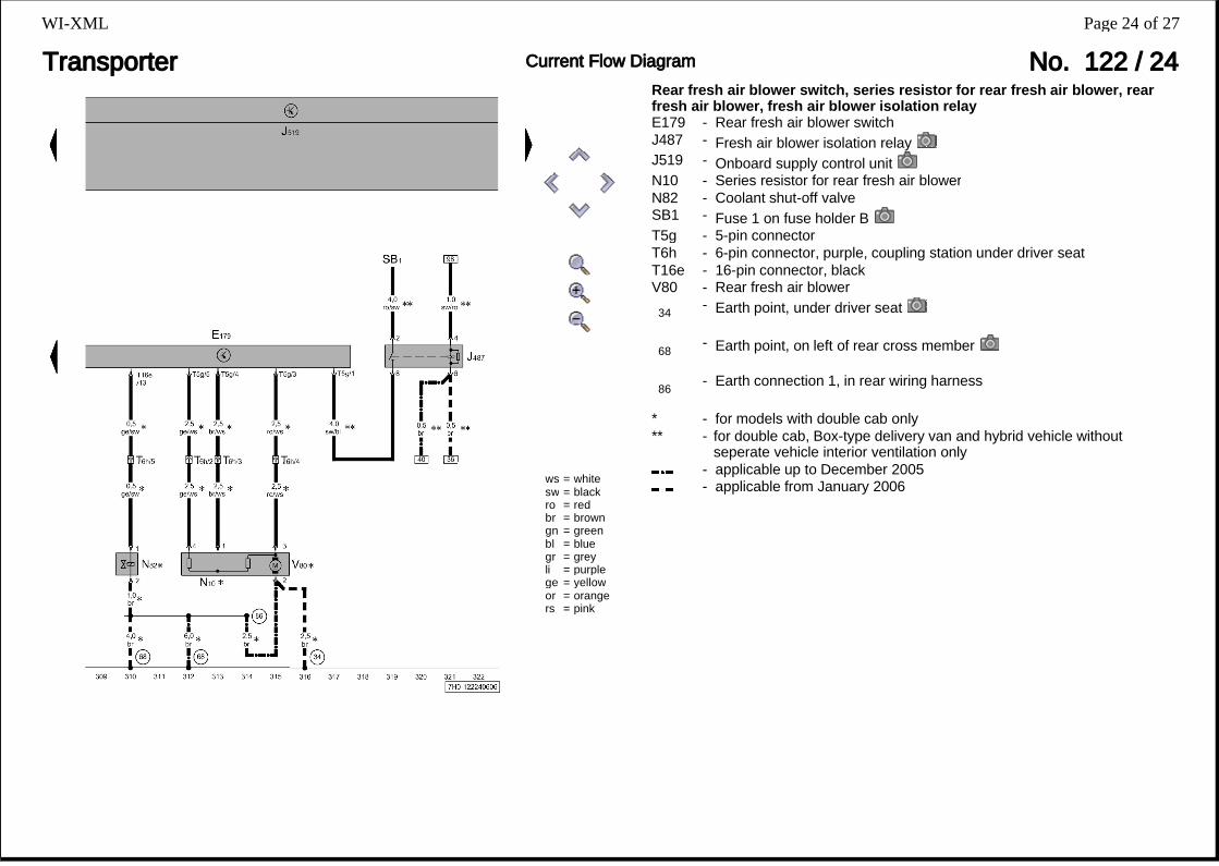
Rear fresh air blower switch, series resistor for rear fresh air blower, rear fresh air blower, fresh air blower isolation relayE179 - Rear fresh air blower switchJ487 - Fresh air blower isolation relayJ519 - Onboard supply control unitN10 - Series resistor for rear fresh air blowerN82 - Coolant shut-off valveSB1 - Fuse 1 on fuse holder BT5g - 5-pin connectorT6h - 6-pin connector, purple, coupling station under driver seatT16e - 16-pin connector, blackV80 - Rear fresh air blower
34 - Earth point, under driver seat
68 - Earth point, on left of rear cross member
86 - Earth connection 1, in rear wiring harness
* - for models with double cab only** - for double cab, Box-type delivery van and hybrid vehicle without
seperate vehicle interior ventilation only- applicable up to December 2005- applicable from January 2006
Page 24 of 27WI-XML

Transporter Current Flow Diagram No. 122 / 25
ws = whitesw = blackro = redbr = browngn = greenbl = bluegr = greyli = purplege = yellowor = orangers = pink
Rear fresh air blower switch, rear air distribution control motor, rear temperature flap motor, potentiometer for control motorE179 - Rear fresh air blower switchG478 - Potentiometer for rear air distribution control motorG479 - Potentiometer for rear temperature flap motorJ519 - Onboard supply control unitT6x - 6-pin connector, purple, coupling station under front passenger seatT16a - 16-pin connector, blackV136 - Rear air distribution control motorV137 - Rear temperature flap control motor
170 - Earth connection 1, in air conditioning system/Climatronic operating unit
wiring harness
427 - Earth connection 3, in right rear end wiring harness
429 - Earth connection 4, in right rear end wiring harness
L46 - Connection (5 Volt), in Climatronic operating unit wiring harness
* - for camper, box-type delivery van and hybrid vehicle with seperate vehicle interior ventilation only
** - for box-type delivery van and hybrid vehicle with seperate vehicle interior ventilation only, not for camper
Page 25 of 27WI-XML
Transporter Current Flow Diagram No. 122 / 26
ws = whitesw = blackro = redbr = browngn = greenbl = bluegr = greyli = purplege = yellowor = orangers = pink
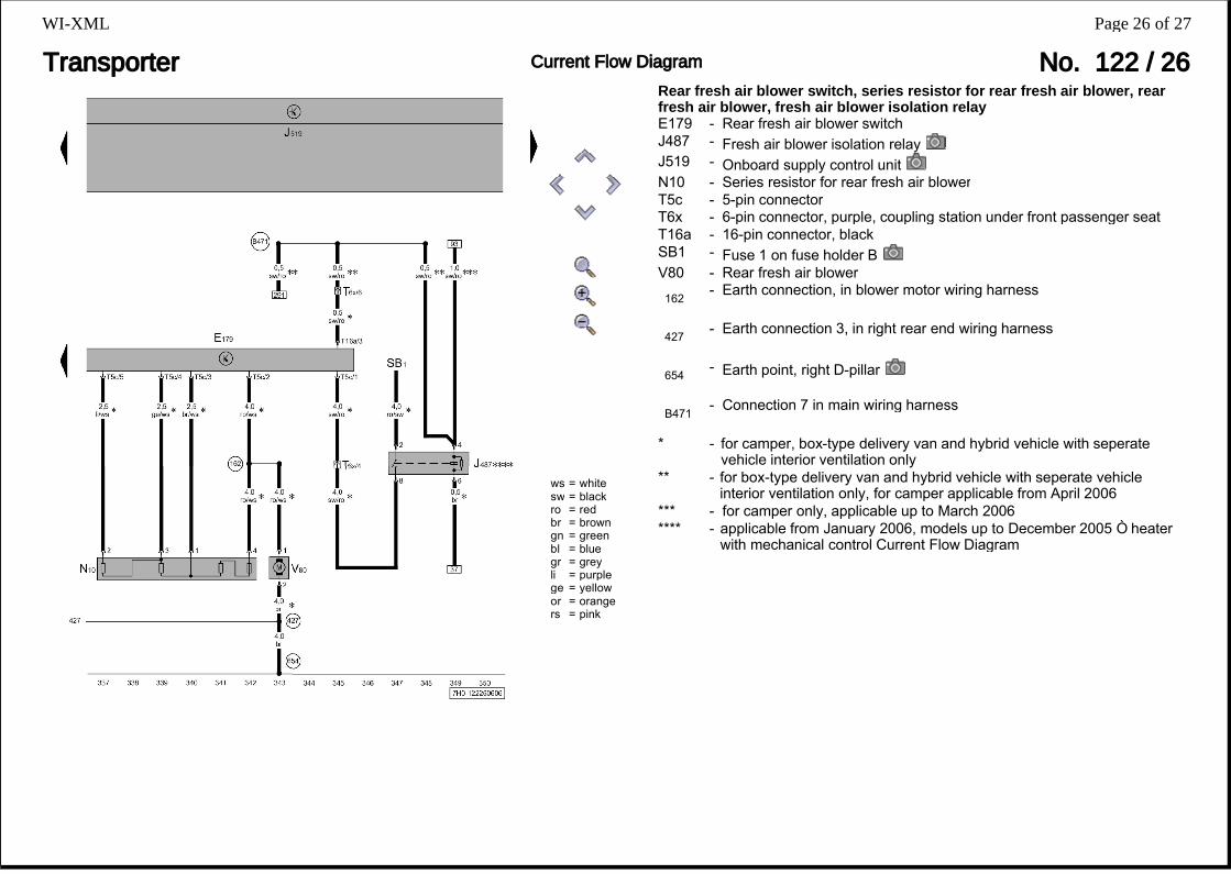
Rear fresh air blower switch, series resistor for rear fresh air blower, rear fresh air blower, fresh air blower isolation relayE179 - Rear fresh air blower switchJ487 - Fresh air blower isolation relayJ519 - Onboard supply control unitN10 - Series resistor for rear fresh air blowerT5c - 5-pin connectorT6x - 6-pin connector, purple, coupling station under front passenger seatT16a - 16-pin connector, blackSB1 - Fuse 1 on fuse holder BV80 - Rear fresh air blower
162 - Earth connection, in blower motor wiring harness
427 - Earth connection 3, in right rear end wiring harness
654 - Earth point, right D-pillar
B471 - Connection 7 in main wiring harness
* - for camper, box-type delivery van and hybrid vehicle with seperate vehicle interior ventilation only
** - for box-type delivery van and hybrid vehicle with seperate vehicle interior ventilation only, for camper applicable from April 2006
*** - for camper only, applicable up to March 2006**** - applicable from January 2006, models up to December 2005 ⇒ heater
with mechanical control Current Flow Diagram
Page 26 of 27WI-XML

Transporter Current Flow Diagram No. 122 / 27
ws = whitesw = blackro = redbr = browngn = greenbl = bluegr = greyli = purplege = yellowor = orangers = pink
Onboard supply control unit, cigarette lighter, glove compartment light, glove compartment light switch, horn or dual tone horn, bonnet contact switchE26 - Glove compartment light switchF266 - Bonnet contact switchH1 - Horn or dual tone hornH7 - Bass tone hornJ519 - Onboard supply control unitL28 - Cigarette lighter illumination bulbSB12 - Fuse 12 on fuse holder BSC17 - Fuse 17 on fuse holder CT4e - 4-pin connector, black, near headlight, front rightT5a - 5-pin connector, brownT6a - 6-pin connector, brownT18 - 18-pin connector, blackU1 - Cigarette lighterW6 - Glove compartment light
380 - Earth connection 15, in main wiring harness
B315 - Positive connection 1 (30a), in main wiring harness
C13 - Positive connection in dual tone horn wiring harness
* - for models with dual tone horn only** - for models without roof console only ⇒ interior lights Current Flow
Diagram*** - for models with roof console only ⇒ interior lights Current Flow Diagram
- applicable up to December 2005- applicable from January 2006
Page 27 of 27WI-XML