transporter current flow diagram no. 638 / 1
TRANSCRIPT
Basic equipment ● Cruise control system ● Multifunction display ● Extended servicing intervals from June 2007
Transporter Current Flow Diagram No. 638 / 1 Edition 02.2010
Notes:
For information concerning
Position of relays and fuses Multi-pin connections Control units and relays Earth connections
→ List of Fitting Locations!
For information concerning
Fault Finding Programs
→ guided fault finding
Стр. 1 из 28WI-XML
11.01.2019file://C:\ElsaWin\docs\slp\N\en-GB\K00589850638.htm#id638015
Transporter Current Flow Diagram No. 638 / 2
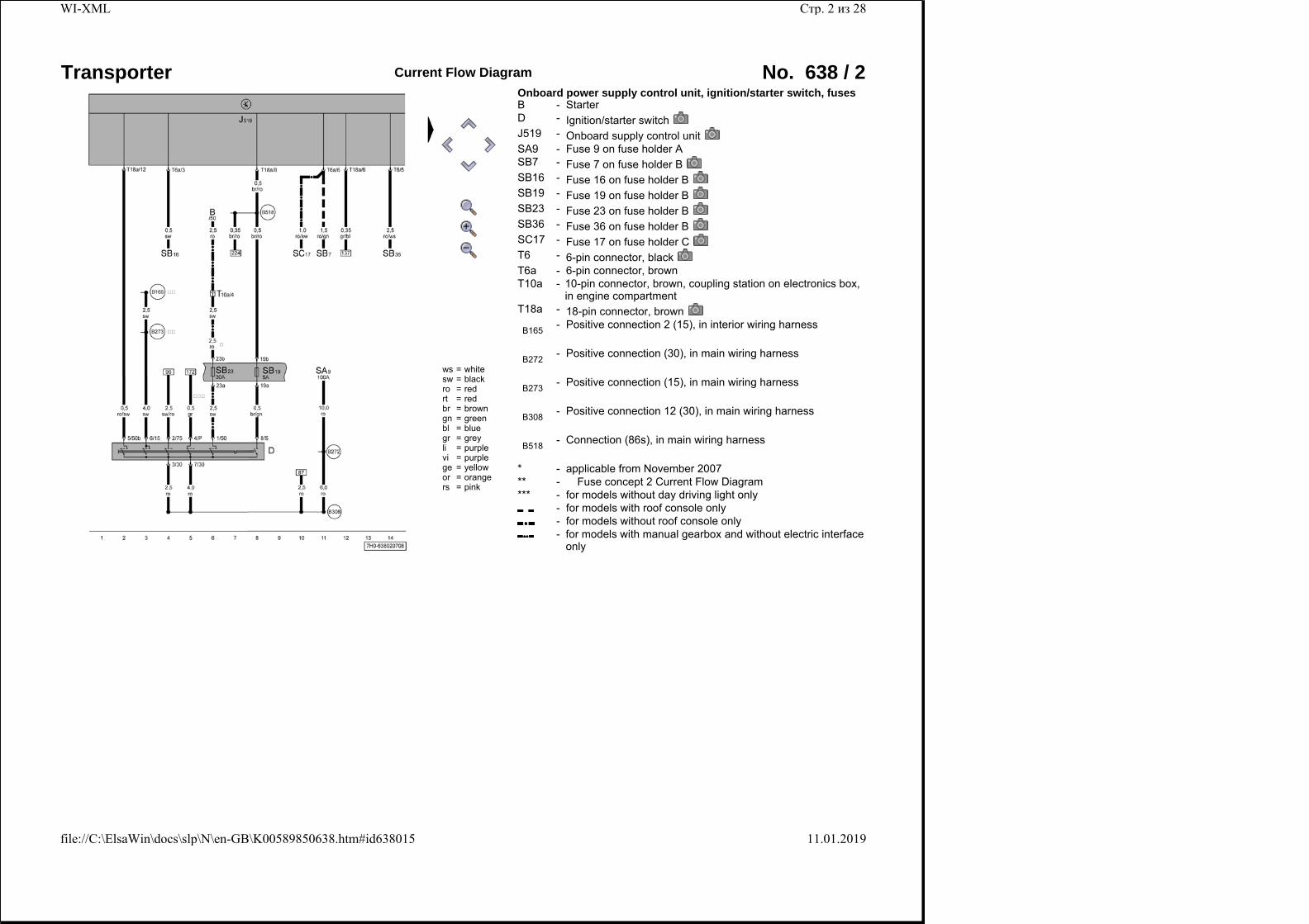
ws = whitesw = blackro = redrt = redbr = browngn = greenbl = bluegr = greyli = purplevi = purplege = yellowor = orangers = pink
Onboard power supply control unit, ignition/starter switch, fuses B - StarterD - Ignition/starter switchJ519 - Onboard supply control unitSA9 - Fuse 9 on fuse holder ASB7 - Fuse 7 on fuse holder BSB16 - Fuse 16 on fuse holder BSB19 - Fuse 19 on fuse holder BSB23 - Fuse 23 on fuse holder BSB36 - Fuse 36 on fuse holder BSC17 - Fuse 17 on fuse holder CT6 - 6-pin connector, blackT6a - 6-pin connector, brownT10a -
10-pin connector, brown, coupling station on electronics box, in engine compartment
T18a - 18-pin connector, brown
B165 - Positive connection 2 (15), in interior wiring harness
B272 - Positive connection (30), in main wiring harness
B273 - Positive connection (15), in main wiring harness
B308 - Positive connection 12 (30), in main wiring harness
B518 - Connection (86s), in main wiring harness
* - applicable from November 2007** - � Fuse concept 2 Current Flow Diagram*** - for models without day driving light only
- for models with roof console only - for models without roof console only -
for models with manual gearbox and without electric interface only
Стр. 2 из 28WI-XML
11.01.2019file://C:\ElsaWin\docs\slp\N\en-GB\K00589850638.htm#id638015
Transporter Current Flow Diagram No. 638 / 3
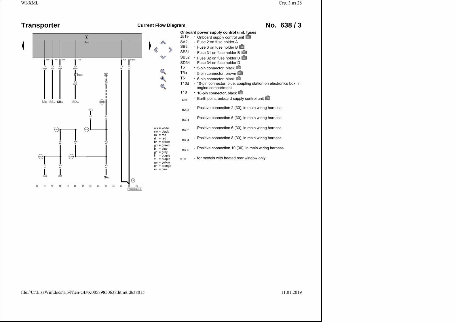
ws = whitesw = blackro = redrt = redbr = browngn = greenbl = bluegr = greyli = purplevi = purplege = yellowor = orangers = pink
Onboard power supply control unit, fuses J519 - Onboard supply control unitSA2 - Fuse 2 on fuse holder ASB3 - Fuse 3 on fuse holder BSB31 - Fuse 31 on fuse holder BSB32 - Fuse 32 on fuse holder BSD34 - Fuse 34 on fuse holder DT5 - 5-pin connector, blackT5a - 5-pin connector, brownT6 - 6-pin connector, blackT10d -
10-pin connector, blue, coupling station on electronics box, in engine compartment
T18 - 18-pin connector, black
636 - Earth point, onboard supply control unit
B298 - Positive connection 2 (30), in main wiring harness
B301 - Positive connection 5 (30), in main wiring harness
B302 - Positive connection 6 (30), in main wiring harness
B304 - Positive connection 8 (30), in main wiring harness
B306 - Positive connection 10 (30), in main wiring harness
- for models with heated rear window only
Стр. 3 из 28WI-XML
11.01.2019file://C:\ElsaWin\docs\slp\N\en-GB\K00589850638.htm#id638015
Transporter Current Flow Diagram No. 638 / 4
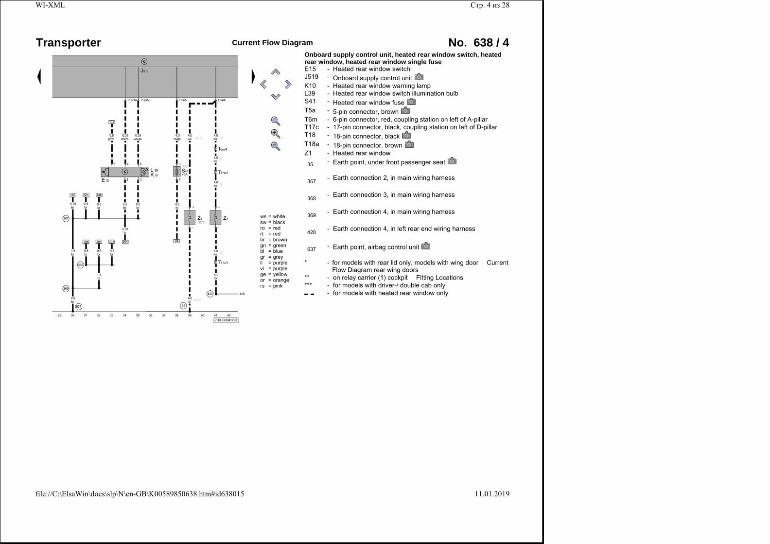
ws = whitesw = blackro = redrt = redbr = browngn = greenbl = bluegr = greyli = purplevi = purplege = yellowor = orangers = pink
Onboard supply control unit, heated rear window switch, heated rear window, heated rear window single fuse E15 - Heated rear window switchJ519 - Onboard supply control unitK10 - Heated rear window warning lampL39 - Heated rear window switch illumination bulbS41 - Heated rear window fuseT5a - 5-pin connector, brownT6m - 6-pin connector, red, coupling station on left of A-pillarT17c - 17-pin connector, black, coupling station on left of D-pillarT18 - 18-pin connector, blackT18a - 18-pin connector, brownZ1 - Heated rear window
35 - Earth point, under front passenger seat
367 - Earth connection 2, in main wiring harness
368 - Earth connection 3, in main wiring harness
369 - Earth connection 4, in main wiring harness
428 - Earth connection 4, in left rear end wiring harness
637 - Earth point, airbag control unit
* - for models with rear lid only, models with wing door � Current Flow Diagram rear wing doors
** - on relay carrier (1) cockpit � Fitting Locations*** - for models with driver-/ double cab only
- for models with heated rear window only
Стр. 4 из 28WI-XML
11.01.2019file://C:\ElsaWin\docs\slp\N\en-GB\K00589850638.htm#id638015
Transporter Current Flow Diagram No. 638 / 5
ws = whitesw = blackro = redrt = redbr = browngn = greenbl = bluegr = greyli = purplevi = purplege = yellowor = orangers = pink
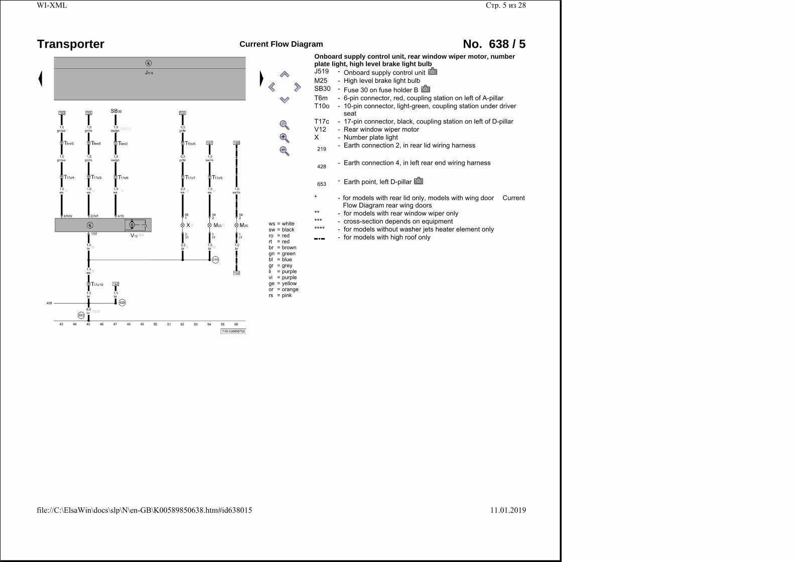
Onboard supply control unit, rear window wiper motor, number plate light, high level brake light bulb J519 - Onboard supply control unitM25 - High level brake light bulbSB30 - Fuse 30 on fuse holder BT6m - 6-pin connector, red, coupling station on left of A-pillarT10o -
10-pin connector, light-green, coupling station under driver seat
T17c - 17-pin connector, black, coupling station on left of D-pillarV12 - Rear window wiper motorX - Number plate light
219 - Earth connection 2, in rear lid wiring harness
428 - Earth connection 4, in left rear end wiring harness
653 - Earth point, left D-pillar
* - for models with rear lid only, models with wing door � Current Flow Diagram rear wing doors
** - for models with rear window wiper only*** - cross-section depends on equipment**** - for models without washer jets heater element only
- for models with high roof only
Стр. 5 из 28WI-XML
11.01.2019file://C:\ElsaWin\docs\slp\N\en-GB\K00589850638.htm#id638015
Transporter Current Flow Diagram No. 638 / 6
ws = whitesw = blackro = redrt = redbr = browngn = greenbl = bluegr = greyli = purplevi = purplege = yellowor = orangers = pink
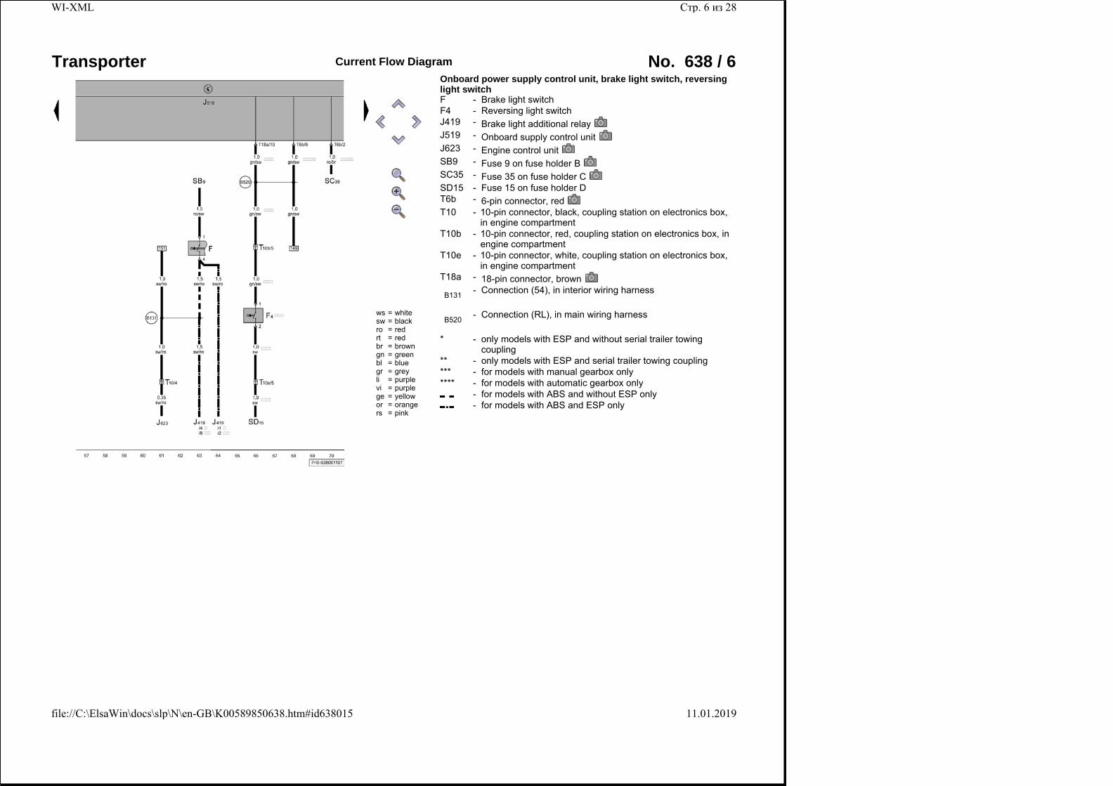
Onboard power supply control unit, brake light switch, reversing light switch F - Brake light switchF4 - Reversing light switchJ419 - Brake light additional relayJ519 - Onboard supply control unitJ623 - Engine control unitSB9 - Fuse 9 on fuse holder BSC35 - Fuse 35 on fuse holder CSD15 - Fuse 15 on fuse holder DT6b - 6-pin connector, redT10 -
10-pin connector, black, coupling station on electronics box, in engine compartment
T10b - 10-pin connector, red, coupling station on electronics box, in engine compartment
T10e - 10-pin connector, white, coupling station on electronics box, in engine compartment
T18a - 18-pin connector, brown
B131 - Connection (54), in interior wiring harness
B520 - Connection (RL), in main wiring harness
* -
only models with ESP and without serial trailer towing coupling
** - only models with ESP and serial trailer towing coupling*** - for models with manual gearbox only**** - for models with automatic gearbox only
- for models with ABS and without ESP only - for models with ABS and ESP only
Стр. 6 из 28WI-XML
11.01.2019file://C:\ElsaWin\docs\slp\N\en-GB\K00589850638.htm#id638015
Transporter Current Flow Diagram No. 638 / 7
ws = whitesw = blackro = redrt = redbr = browngn = greenbl = bluegr = greyli = purplevi = purplege = yellowor = orangers = pink
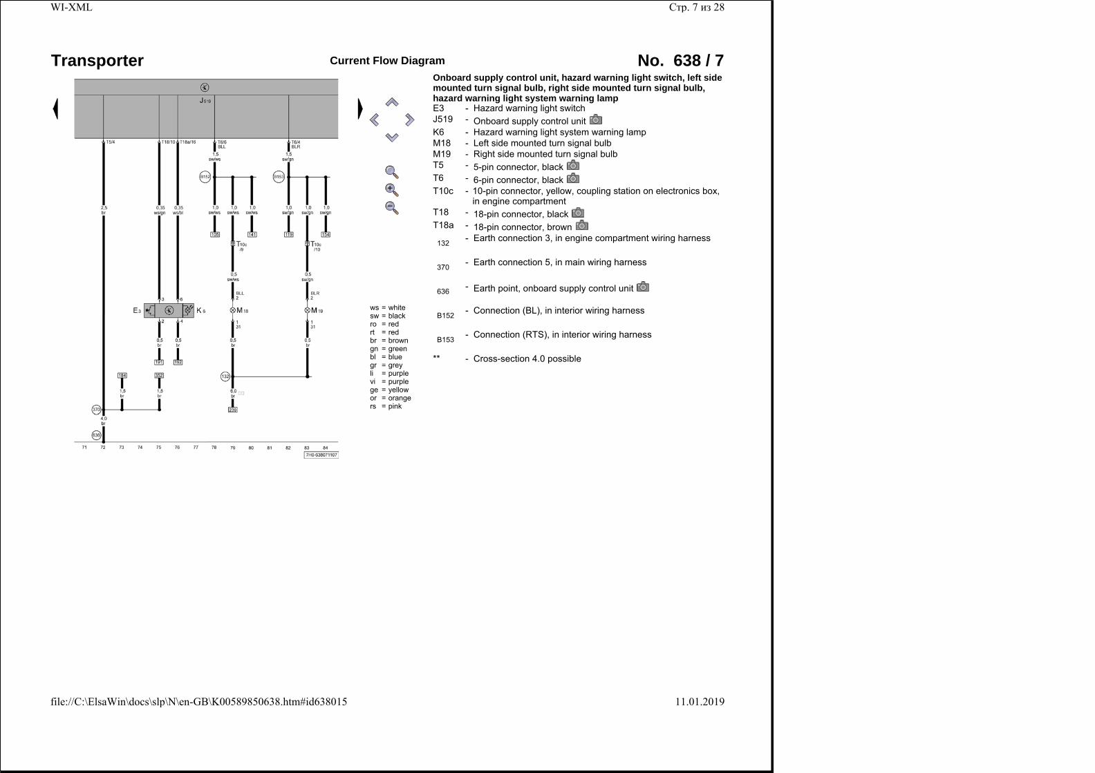
Onboard supply control unit, hazard warning light switch, left side mounted turn signal bulb, right side mounted turn signal bulb, hazard warning light system warning lamp E3 - Hazard warning light switchJ519 - Onboard supply control unitK6 - Hazard warning light system warning lampM18 - Left side mounted turn signal bulbM19 - Right side mounted turn signal bulbT5 - 5-pin connector, blackT6 - 6-pin connector, blackT10c -
10-pin connector, yellow, coupling station on electronics box, in engine compartment
T18 - 18-pin connector, blackT18a - 18-pin connector, brown
132 - Earth connection 3, in engine compartment wiring harness
370 - Earth connection 5, in main wiring harness
636 - Earth point, onboard supply control unit
B152 - Connection (BL), in interior wiring harness
B153 - Connection (RTS), in interior wiring harness
** - Cross-section 4.0 possible
Стр. 7 из 28WI-XML
11.01.2019file://C:\ElsaWin\docs\slp\N\en-GB\K00589850638.htm#id638015
Transporter Current Flow Diagram No. 638 / 8
ws = whitesw = blackro = redrt = redbr = browngn = greenbl = bluegr = greyli = purplevi = purplege = yellowor = orangers = pink
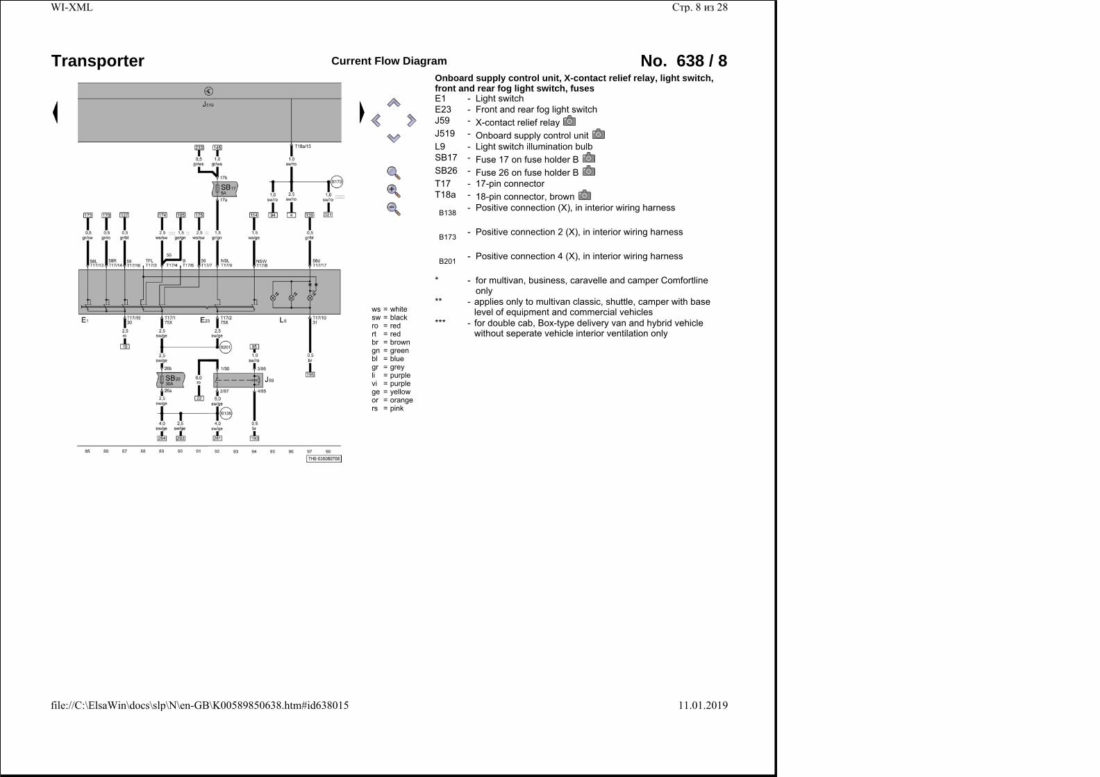
Onboard supply control unit, X-contact relief relay, light switch, front and rear fog light switch, fuses E1 - Light switchE23 - Front and rear fog light switchJ59 - X-contact relief relayJ519 - Onboard supply control unitL9 - Light switch illumination bulbSB17 - Fuse 17 on fuse holder BSB26 - Fuse 26 on fuse holder BT17 - 17-pin connectorT18a - 18-pin connector, brown
B138 - Positive connection (X), in interior wiring harness
B173 - Positive connection 2 (X), in interior wiring harness
B201 - Positive connection 4 (X), in interior wiring harness
* - for multivan, business, caravelle and camper Comfortline only
** - applies only to multivan classic, shuttle, camper with base level of equipment and commercial vehicles
*** - for double cab, Box-type delivery van and hybrid vehicle without seperate vehicle interior ventilation only
Стр. 8 из 28WI-XML
11.01.2019file://C:\ElsaWin\docs\slp\N\en-GB\K00589850638.htm#id638015
Transporter Current Flow Diagram No. 638 / 9
ws = whitesw = blackro = redrt = redbr = browngn = greenbl = bluegr = greyli = purplevi = purplege = yellowor = orangers = pink
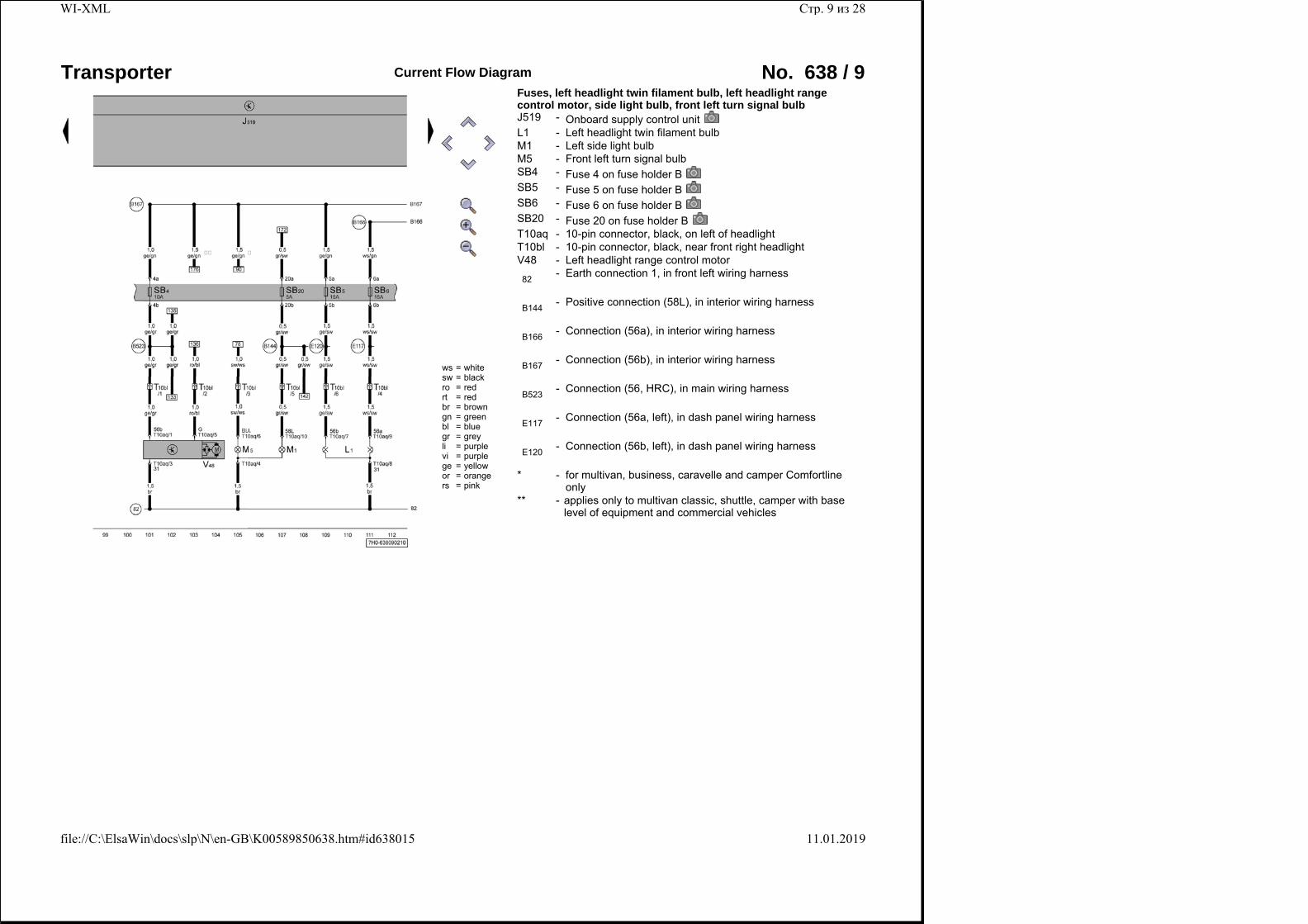
Fuses, left headlight twin filament bulb, left headlight range control motor, side light bulb, front left turn signal bulb J519 - Onboard supply control unitL1 - Left headlight twin filament bulbM1 - Left side light bulbM5 - Front left turn signal bulbSB4 - Fuse 4 on fuse holder BSB5 - Fuse 5 on fuse holder BSB6 - Fuse 6 on fuse holder BSB20 - Fuse 20 on fuse holder BT10aq - 10-pin connector, black, on left of headlightT10bl - 10-pin connector, black, near front right headlightV48 - Left headlight range control motor
82 - Earth connection 1, in front left wiring harness
B144 - Positive connection (58L), in interior wiring harness
B166 - Connection (56a), in interior wiring harness
B167 - Connection (56b), in interior wiring harness
B523 - Connection (56, HRC), in main wiring harness
E117 - Connection (56a, left), in dash panel wiring harness
E120 - Connection (56b, left), in dash panel wiring harness
* - for multivan, business, caravelle and camper Comfortline only
** - applies only to multivan classic, shuttle, camper with base level of equipment and commercial vehicles
Стр. 9 из 28WI-XML
11.01.2019file://C:\ElsaWin\docs\slp\N\en-GB\K00589850638.htm#id638015
Transporter Current Flow Diagram No. 638 / 10
ws = whitesw = blackro = redrt = redbr = browngn = greenbl = bluegr = greyli = purplevi = purplege = yellowor = orangers = pink
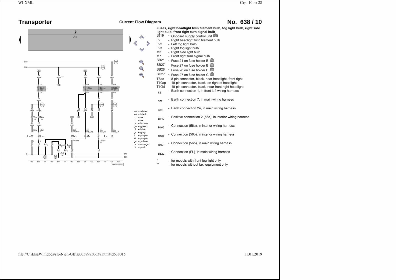
Fuses, right headlight twin filament bulb, fog light bulb, right side light bulb, front right turn signal bulb J519 - Onboard supply control unitL2 - Right headlight twin filament bulbL22 - Left fog light bulbL23 - Right fog light bulbM3 - Right side light bulbM7 - Front right turn signal bulbSB21 - Fuse 21 on fuse holder BSB27 - Fuse 27 on fuse holder BSB28 - Fuse 28 on fuse holder BSC27 - Fuse 27 on fuse holder CT8ae - 8-pin connector, black, near headlight, front rightT10ap - 10-pin connector, black, on right of headlightT10bl - 10-pin connector, black, near front right headlight
82 - Earth connection 1, in front left wiring harness
372 - Earth connection 7, in main wiring harness
389 - Earth connection 24, in main wiring harness
B142 - Positive connection 2 (56a), in interior wiring harness
B166 - Connection (56a), in interior wiring harness
B167 - Connection (56b), in interior wiring harness
B456 - Connection (56b), in main wiring harness
B522 - Connection (FL), in main wiring harness
* - for models with front fog light only** - for models without taxi equipment only
Стр. 10 из 28WI-XML
11.01.2019file://C:\ElsaWin\docs\slp\N\en-GB\K00589850638.htm#id638015
Transporter Current Flow Diagram No. 638 / 11
ws = whitesw = blackro = redrt = redbr = browngn = greenbl = bluegr = greyli = purplevi = purplege = yellowor = orangers = pink
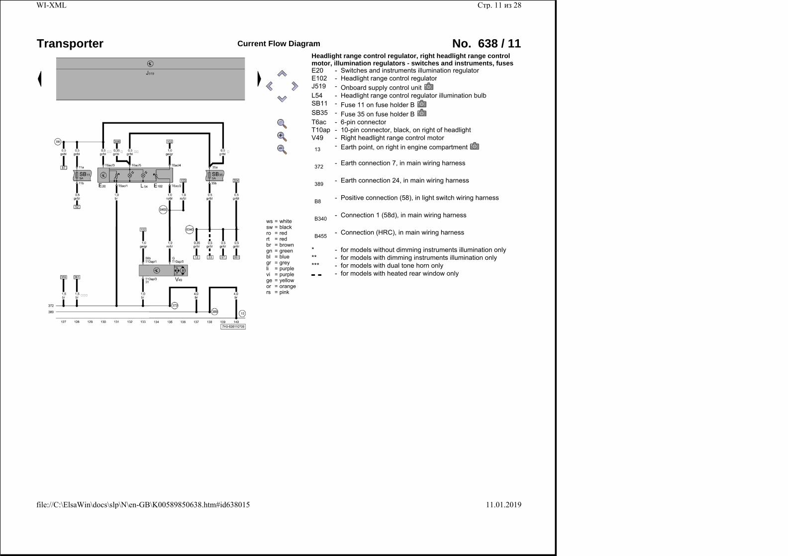
Headlight range control regulator, right headlight range control motor, illumination regulators - switches and instruments, fuses E20 - Switches and instruments illumination regulatorE102 - Headlight range control regulatorJ519 - Onboard supply control unitL54 - Headlight range control regulator illumination bulbSB11 - Fuse 11 on fuse holder BSB35 - Fuse 35 on fuse holder BT6ac - 6-pin connectorT10ap - 10-pin connector, black, on right of headlightV49 - Right headlight range control motor
13 - Earth point, on right in engine compartment
372 - Earth connection 7, in main wiring harness
389 - Earth connection 24, in main wiring harness
B8 - Positive connection (58), in light switch wiring harness
B340 - Connection 1 (58d), in main wiring harness
B455 - Connection (HRC), in main wiring harness
* - for models without dimming instruments illumination only** - for models with dimming instruments illumination only*** - for models with dual tone horn only
- for models with heated rear window only
Стр. 11 из 28WI-XML
11.01.2019file://C:\ElsaWin\docs\slp\N\en-GB\K00589850638.htm#id638015
Transporter Current Flow Diagram No. 638 / 12
ws = whitesw = blackro = redrt = redbr = browngn = greenbl = bluegr = greyli = purplevi = purplege = yellowor = orangers = pink
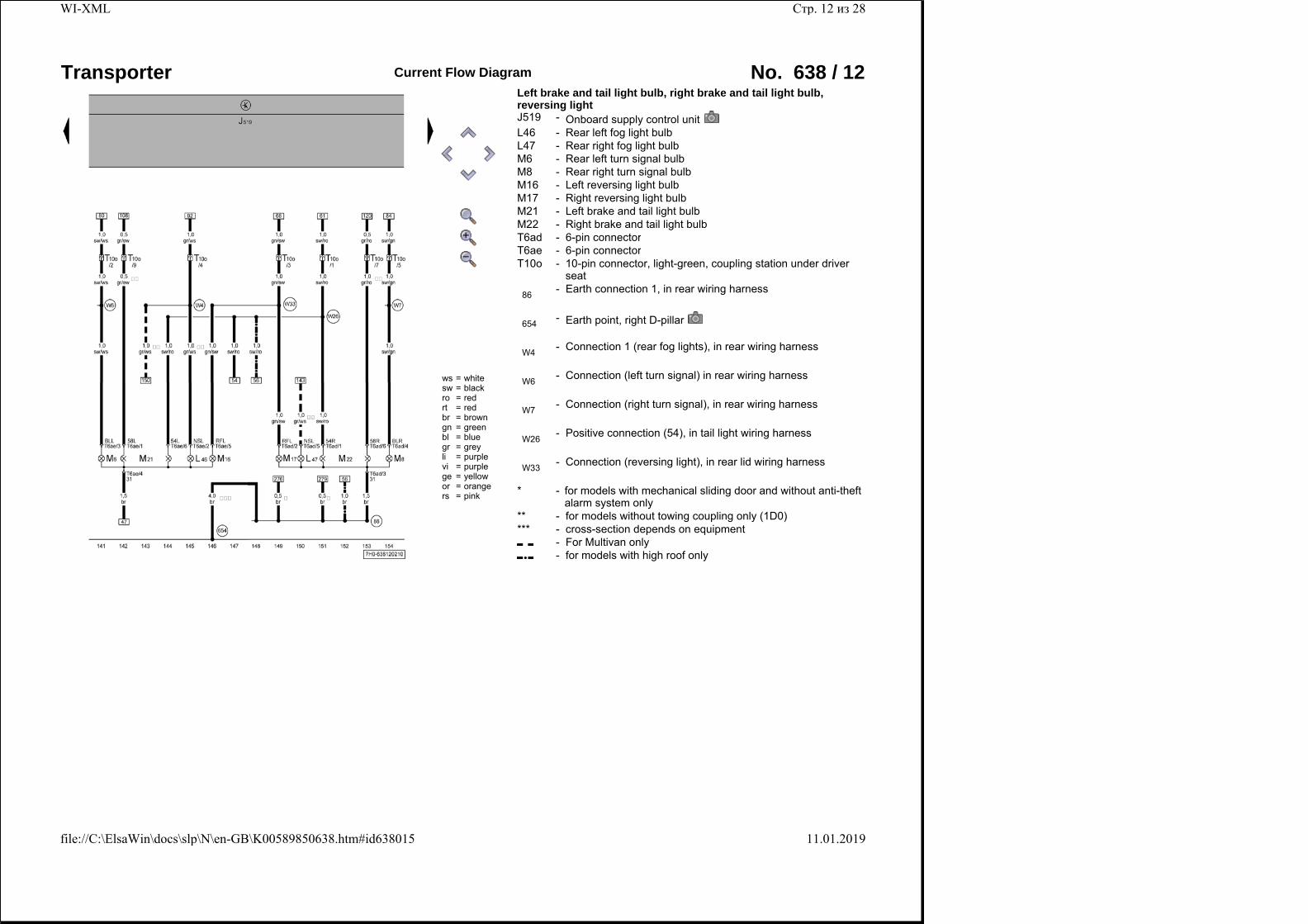
Left brake and tail light bulb, right brake and tail light bulb, reversing light J519 - Onboard supply control unitL46 - Rear left fog light bulbL47 - Rear right fog light bulbM6 - Rear left turn signal bulbM8 - Rear right turn signal bulbM16 - Left reversing light bulbM17 - Right reversing light bulbM21 - Left brake and tail light bulbM22 - Right brake and tail light bulbT6ad - 6-pin connectorT6ae - 6-pin connectorT10o -
10-pin connector, light-green, coupling station under driver seat
86 - Earth connection 1, in rear wiring harness
654 - Earth point, right D-pillar
W4 - Connection 1 (rear fog lights), in rear wiring harness
W6 - Connection (left turn signal) in rear wiring harness
W7 - Connection (right turn signal), in rear wiring harness
W26 - Positive connection (54), in tail light wiring harness
W33 - Connection (reversing light), in rear lid wiring harness
* - for models with mechanical sliding door and without anti-theft alarm system only
** - for models without towing coupling only (1D0)*** - cross-section depends on equipment
- For Multivan only - for models with high roof only
Стр. 12 из 28WI-XML
11.01.2019file://C:\ElsaWin\docs\slp\N\en-GB\K00589850638.htm#id638015
Transporter Current Flow Diagram No. 638 / 13
ws = whitesw = blackro = redrt = redbr = browngn = greenbl = bluegr = greyli = purplevi = purplege = yellowor = orangers = pink
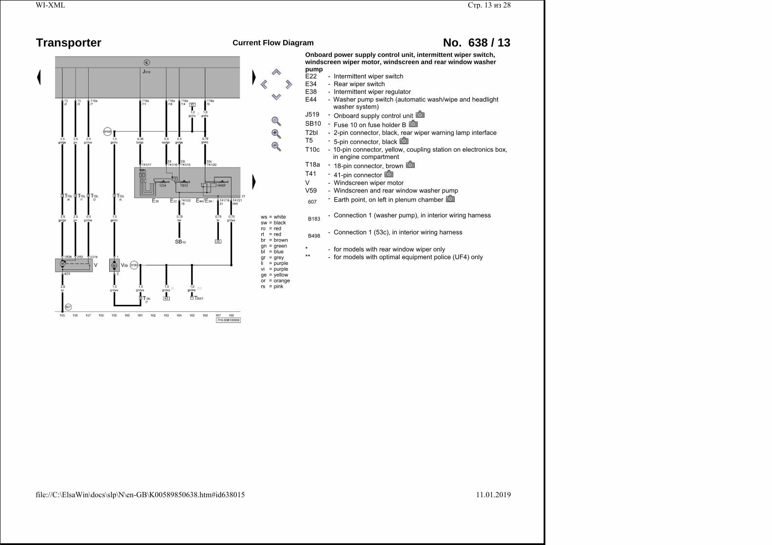
Onboard power supply control unit, intermittent wiper switch, windscreen wiper motor, windscreen and rear window washer pump E22 - Intermittent wiper switchE34 - Rear wiper switchE38 - Intermittent wiper regulatorE44 -
Washer pump switch (automatic wash/wipe and headlight washer system)
J519 - Onboard supply control unitSB10 - Fuse 10 on fuse holder BT2bl - 2-pin connector, black, rear wiper warning lamp interfaceT5 - 5-pin connector, blackT10c -
10-pin connector, yellow, coupling station on electronics box, in engine compartment
T18a - 18-pin connector, brownT41 - 41-pin connectorV - Windscreen wiper motorV59 - Windscreen and rear window washer pump
607 - Earth point, on left in plenum chamber
B183 - Connection 1 (washer pump), in interior wiring harness
B498 - Connection 1 (53c), in interior wiring harness
* - for models with rear window wiper only** - for models with optimal equipment police (UF4) only
Стр. 13 из 28WI-XML
11.01.2019file://C:\ElsaWin\docs\slp\N\en-GB\K00589850638.htm#id638015
Transporter Current Flow Diagram No. 638 / 14
ws = whitesw = blackro = redrt = redbr = browngn = greenbl = bluegr = greyli = purplevi = purplege = yellowor = orangers = pink
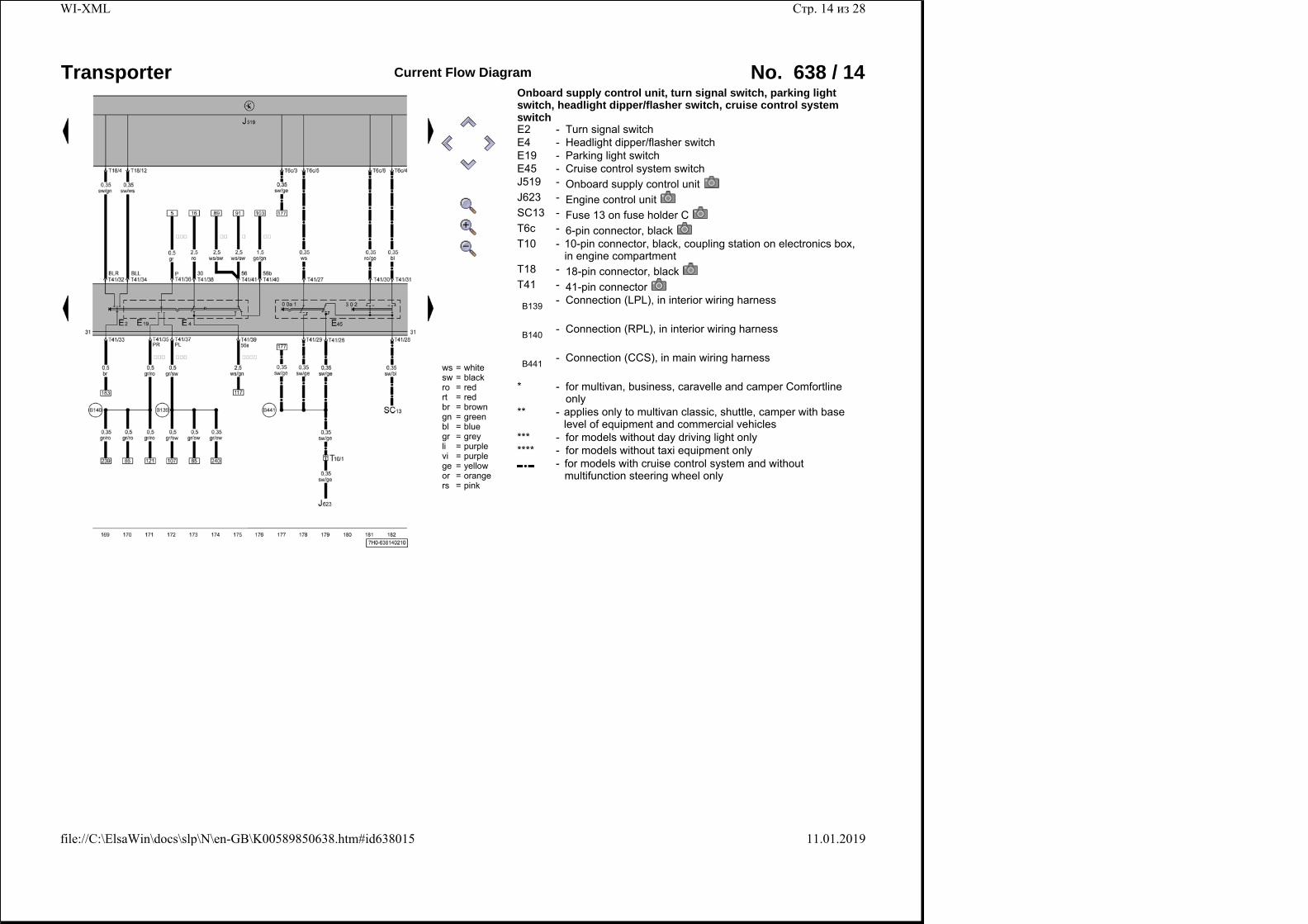
Onboard supply control unit, turn signal switch, parking light switch, headlight dipper/flasher switch, cruise control system switch E2 - Turn signal switchE4 - Headlight dipper/flasher switchE19 - Parking light switchE45 - Cruise control system switchJ519 - Onboard supply control unitJ623 - Engine control unitSC13 - Fuse 13 on fuse holder CT6c - 6-pin connector, blackT10 -
10-pin connector, black, coupling station on electronics box, in engine compartment
T18 - 18-pin connector, blackT41 - 41-pin connector
B139 - Connection (LPL), in interior wiring harness
B140 - Connection (RPL), in interior wiring harness
B441 - Connection (CCS), in main wiring harness
* - for multivan, business, caravelle and camper Comfortline only
** - applies only to multivan classic, shuttle, camper with base level of equipment and commercial vehicles
*** - for models without day driving light only**** - for models without taxi equipment only
- for models with cruise control system and without multifunction steering wheel only
Стр. 14 из 28WI-XML
11.01.2019file://C:\ElsaWin\docs\slp\N\en-GB\K00589850638.htm#id638015
Transporter Current Flow Diagram No. 638 / 15
ws = whitesw = blackro = redrt = redbr = browngn = greenbl = bluegr = greyli = purplevi = purplege = yellowor = orangers = pink
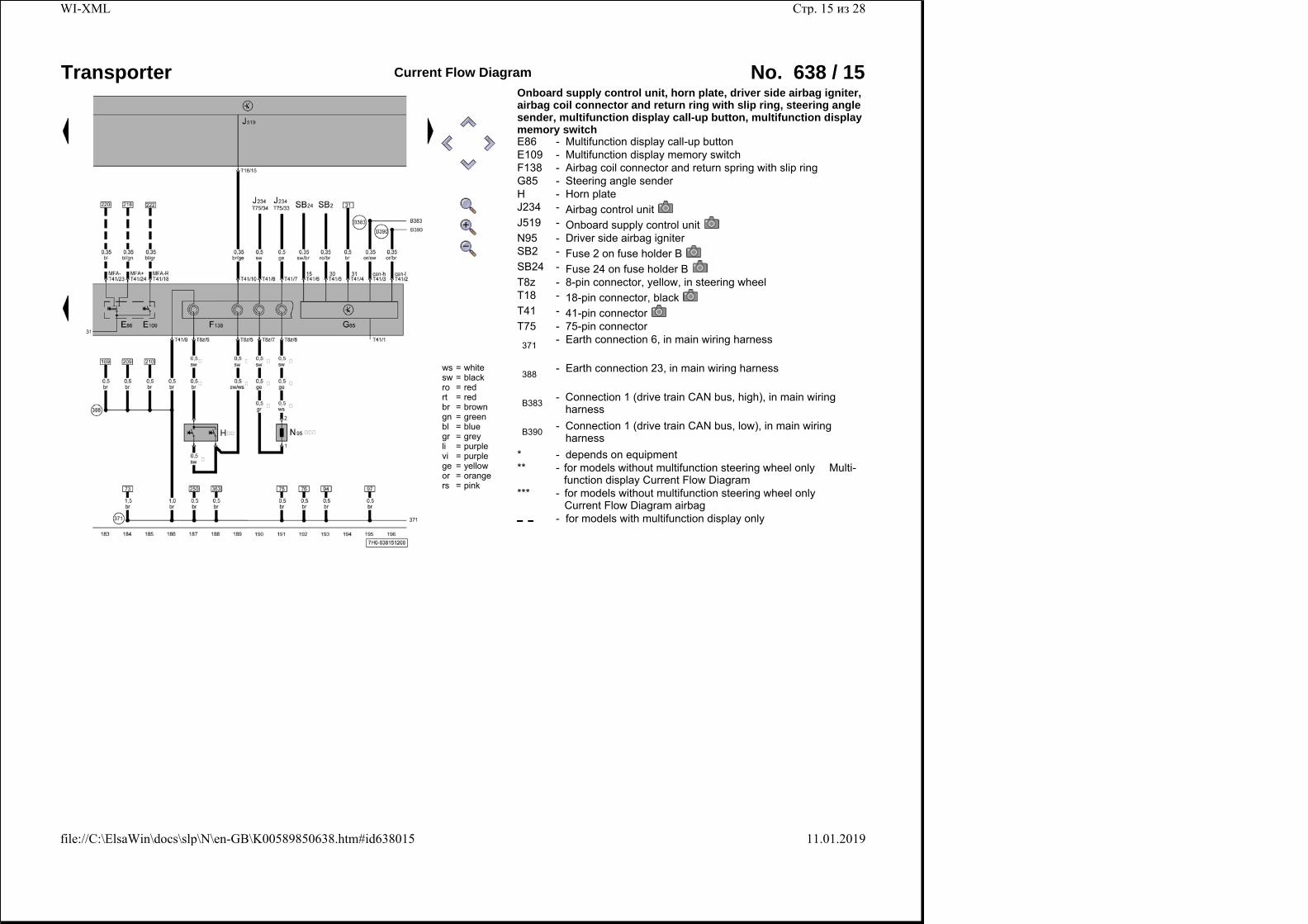
Onboard supply control unit, horn plate, driver side airbag igniter, airbag coil connector and return ring with slip ring, steering angle sender, multifunction display call-up button, multifunction display memory switch E86 - Multifunction display call-up buttonE109 - Multifunction display memory switchF138 - Airbag coil connector and return spring with slip ringG85 - Steering angle senderH - Horn plateJ234 - Airbag control unitJ519 - Onboard supply control unitN95 - Driver side airbag igniterSB2 - Fuse 2 on fuse holder BSB24 - Fuse 24 on fuse holder BT8z - 8-pin connector, yellow, in steering wheelT18 - 18-pin connector, blackT41 - 41-pin connectorT75 - 75-pin connector
371 - Earth connection 6, in main wiring harness
388 - Earth connection 23, in main wiring harness
B383 -
Connection 1 (drive train CAN bus, high), in main wiring harness
B390 -
Connection 1 (drive train CAN bus, low), in main wiring harness
* - depends on equipment** -
for models without multifunction steering wheel only � Multi-function display Current Flow Diagram
*** - for models without multifunction steering wheel only � Current Flow Diagram airbag
- for models with multifunction display only
Стр. 15 из 28WI-XML
11.01.2019file://C:\ElsaWin\docs\slp\N\en-GB\K00589850638.htm#id638015
Transporter Current Flow Diagram No. 638 / 16
ws = whitesw = blackro = redrt = redbr = browngn = greenbl = bluegr = greyli = purplevi = purplege = yellowor = orangers = pink
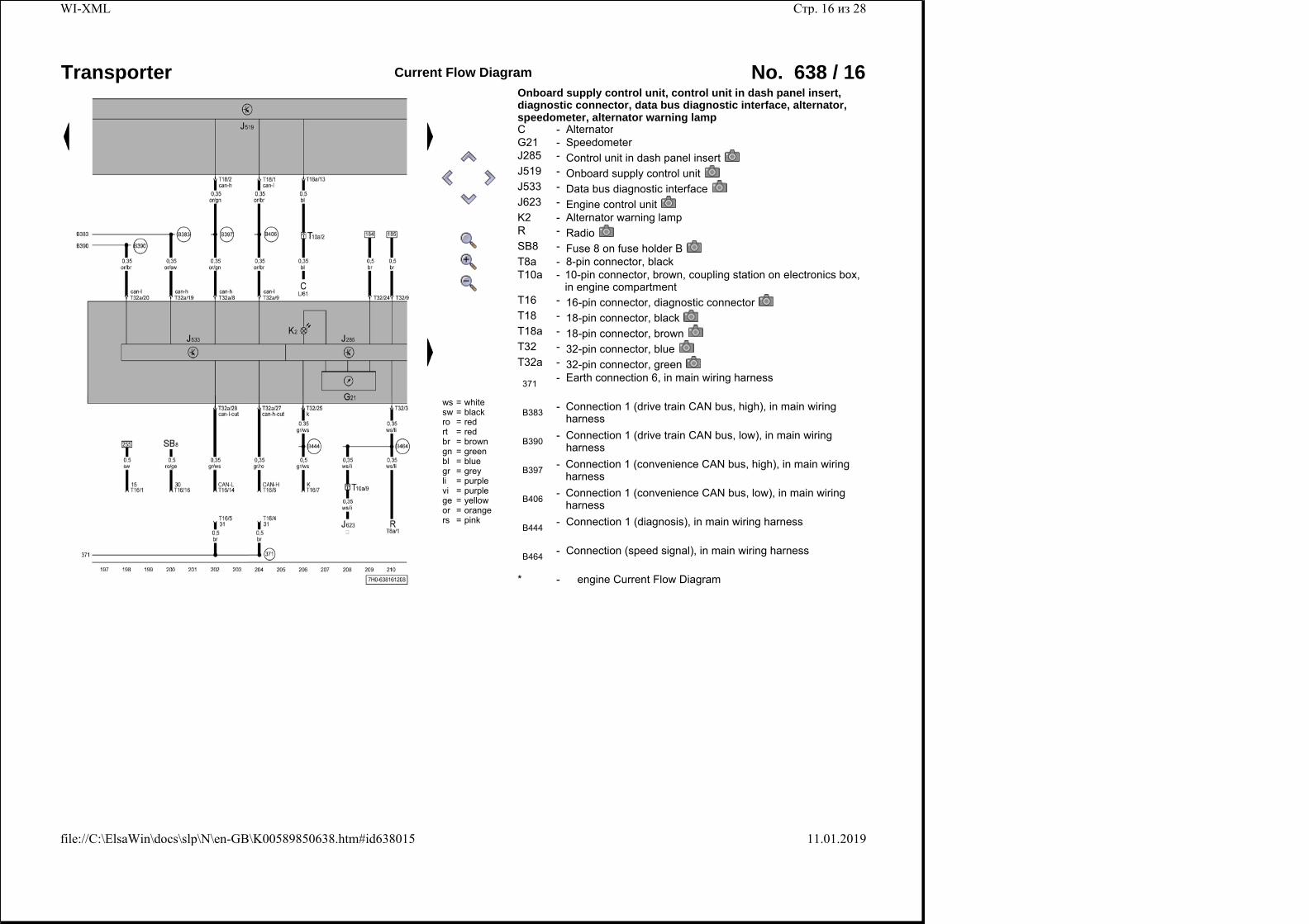
Onboard supply control unit, control unit in dash panel insert, diagnostic connector, data bus diagnostic interface, alternator, speedometer, alternator warning lamp C - AlternatorG21 - SpeedometerJ285 - Control unit in dash panel insertJ519 - Onboard supply control unitJ533 - Data bus diagnostic interfaceJ623 - Engine control unitK2 - Alternator warning lampR - RadioSB8 - Fuse 8 on fuse holder BT8a - 8-pin connector, blackT10a -
10-pin connector, brown, coupling station on electronics box, in engine compartment
T16 - 16-pin connector, diagnostic connectorT18 - 18-pin connector, blackT18a - 18-pin connector, brownT32 - 32-pin connector, blueT32a - 32-pin connector, green
371 - Earth connection 6, in main wiring harness
B383 -
Connection 1 (drive train CAN bus, high), in main wiring harness
B390 -
Connection 1 (drive train CAN bus, low), in main wiring harness
B397 -
Connection 1 (convenience CAN bus, high), in main wiring harness
B406 -
Connection 1 (convenience CAN bus, low), in main wiring harness
B444 - Connection 1 (diagnosis), in main wiring harness
B464 - Connection (speed signal), in main wiring harness
* - � engine Current Flow Diagram
Стр. 16 из 28WI-XML
11.01.2019file://C:\ElsaWin\docs\slp\N\en-GB\K00589850638.htm#id638015
Transporter Current Flow Diagram No. 638 / 17
ws = whitesw = blackro = redrt = redbr = browngn = greenbl = bluegr = greyli = purplevi = purplege = yellowor = orangers = pink
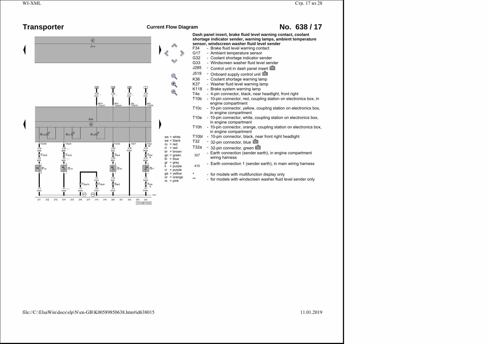
Dash panel insert, brake fluid level warning contact, coolant shortage indicator sender, warning lamps, ambient temperature sensor, windscreen washer fluid level sender F34 - Brake fluid level warning contactG17 - Ambient temperature sensorG32 - Coolant shortage indicator senderG33 - Windscreen washer fluid level senderJ285 - Control unit in dash panel insertJ519 - Onboard supply control unitK36 - Coolant shortage warning lampK37 - Washer fluid level warning lampK118 - Brake system warning lampT4e - 4-pin connector, black, near headlight, front rightT10b -
10-pin connector, red, coupling station on electronics box, in engine compartment
T10c - 10-pin connector, yellow, coupling station on electronics box, in engine compartment
T10e - 10-pin connector, white, coupling station on electronics box, in engine compartment
T10h - 10-pin connector, orange, coupling station on electronics box, in engine compartment
T10bl - 10-pin connector, black, near front right headlightT32 - 32-pin connector, blueT32a - 32-pin connector, green
327 -
Earth connection (sender earth), in engine compartment wiring harness
410 - Earth connection 1 (sender earth), in main wiring harness
* - for models with multifunction display only** - for models with windscreen washer fluid level sender only
Стр. 17 из 28WI-XML
11.01.2019file://C:\ElsaWin\docs\slp\N\en-GB\K00589850638.htm#id638015
Transporter Current Flow Diagram No. 638 / 18
ws = whitesw = blackro = redrt = redbr = browngn = greenbl = bluegr = greyli = purplevi = purplege = yellowor = orangers = pink
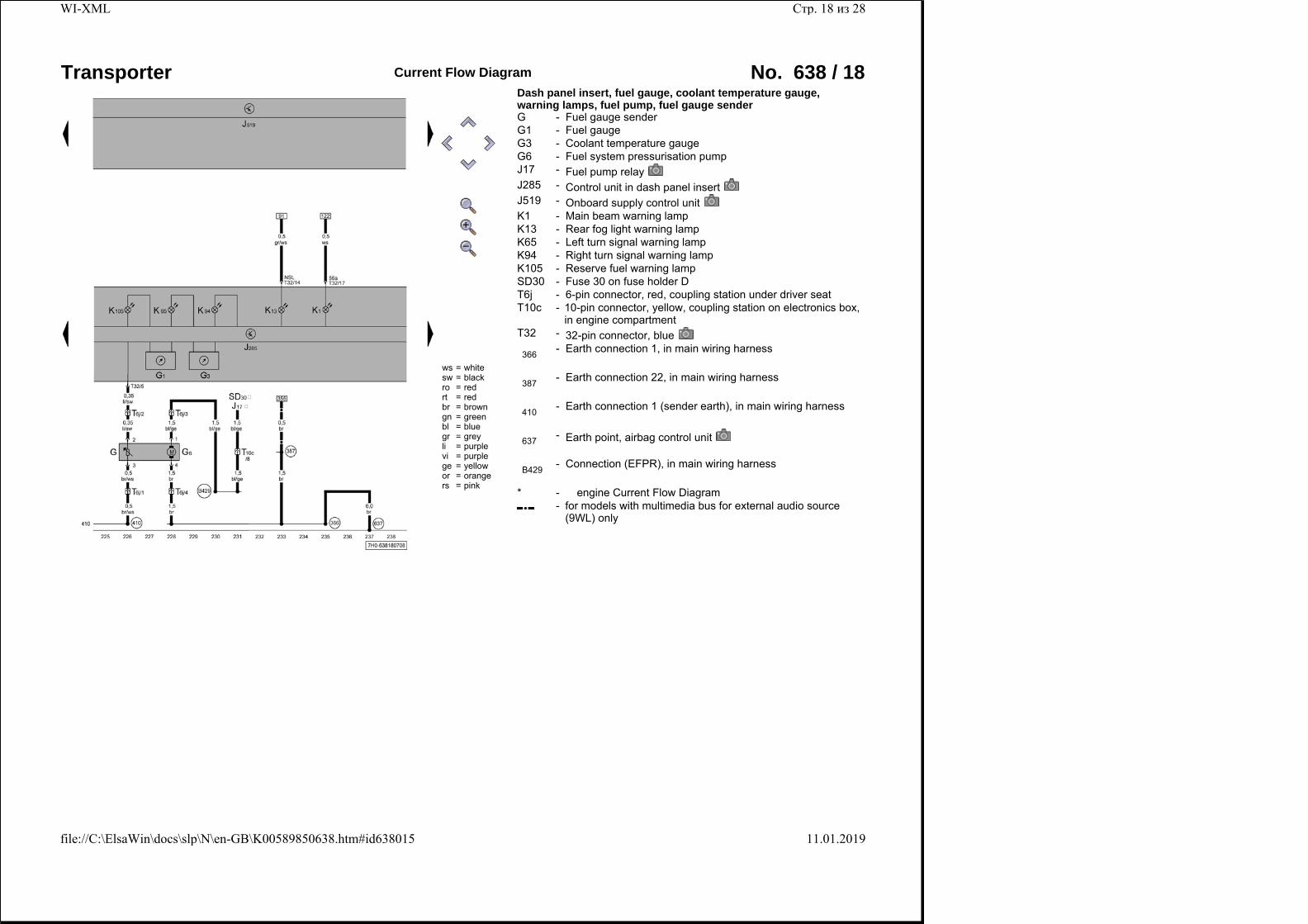
Dash panel insert, fuel gauge, coolant temperature gauge, warning lamps, fuel pump, fuel gauge sender G - Fuel gauge senderG1 - Fuel gaugeG3 - Coolant temperature gaugeG6 - Fuel system pressurisation pumpJ17 - Fuel pump relayJ285 - Control unit in dash panel insertJ519 - Onboard supply control unitK1 - Main beam warning lampK13 - Rear fog light warning lampK65 - Left turn signal warning lampK94 - Right turn signal warning lampK105 - Reserve fuel warning lampSD30 - Fuse 30 on fuse holder DT6j - 6-pin connector, red, coupling station under driver seatT10c -
10-pin connector, yellow, coupling station on electronics box, in engine compartment
T32 - 32-pin connector, blue
366 - Earth connection 1, in main wiring harness
387 - Earth connection 22, in main wiring harness
410 - Earth connection 1 (sender earth), in main wiring harness
637 - Earth point, airbag control unit
B429 - Connection (EFPR), in main wiring harness
* - � engine Current Flow Diagram -
for models with multimedia bus for external audio source (9WL) only
Стр. 18 из 28WI-XML
11.01.2019file://C:\ElsaWin\docs\slp\N\en-GB\K00589850638.htm#id638015
Transporter Current Flow Diagram No. 638 / 19
ws = whitesw = blackro = redrt = redbr = browngn = greenbl = bluegr = greyli = purplevi = purplege = yellowor = orangers = pink
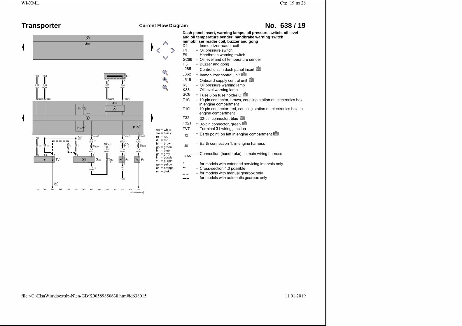
Dash panel insert, warning lamps, oil pressure switch, oil level and oil temperature sender, handbrake warning switch, immobiliser reader coil, buzzer and gong D2 - Immobilizer reader coilF1 - Oil pressure switchF9 - Handbrake warning switchG266 - Oil level and oil temperature senderH3 - Buzzer and gongJ285 - Control unit in dash panel insertJ362 - Immobilizer control unitJ519 - Onboard supply control unitK3 - Oil pressure warning lampK38 - Oil level warning lampSC6 - Fuse 6 on fuse holder CT10a -
10-pin connector, brown, coupling station on electronics box, in engine compartment
T10b - 10-pin connector, red, coupling station on electronics box, in engine compartment
T32 - 32-pin connector, blueT32a - 32-pin connector, greenTV7 - Terminal 31 wiring junction
12 - Earth point, on left in engine compartment
281 - Earth connection 1, in engine harness
B527 - Connection (handbrake), in main wiring harness
* - for models with extended servicing intervals only** - Cross-section 4.0 possible
- for models with manual gearbox only - for models with automatic gearbox only
Стр. 19 из 28WI-XML
11.01.2019file://C:\ElsaWin\docs\slp\N\en-GB\K00589850638.htm#id638015
Transporter Current Flow Diagram No. 638 / 20
ws = whitesw = blackro = redrt = redbr = browngn = greenbl = bluegr = greyli = purplevi = purplege = yellowor = orangers = pink
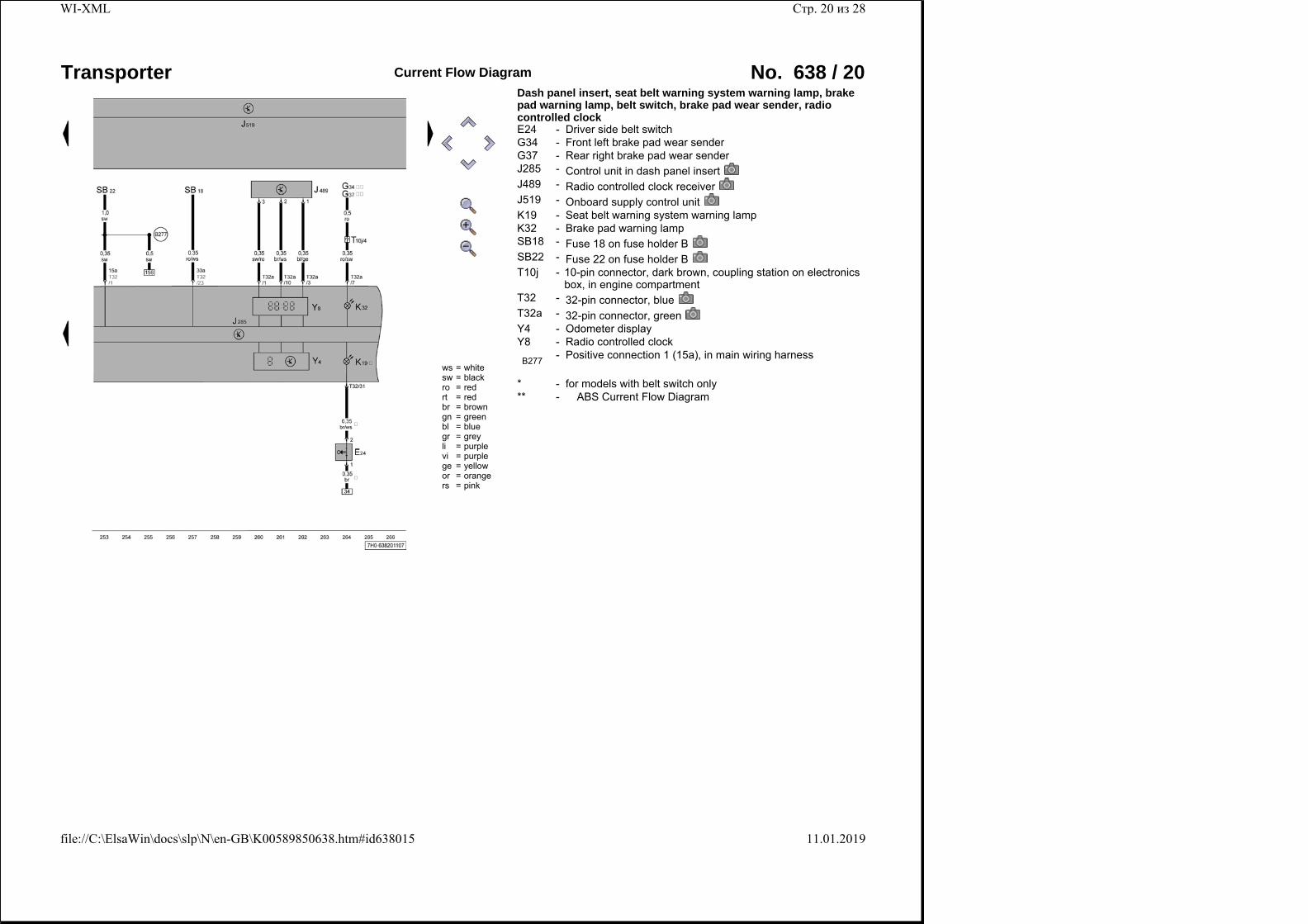
Dash panel insert, seat belt warning system warning lamp, brake pad warning lamp, belt switch, brake pad wear sender, radio controlled clock E24 - Driver side belt switchG34 - Front left brake pad wear senderG37 - Rear right brake pad wear senderJ285 - Control unit in dash panel insertJ489 - Radio controlled clock receiverJ519 - Onboard supply control unitK19 - Seat belt warning system warning lampK32 - Brake pad warning lampSB18 - Fuse 18 on fuse holder BSB22 - Fuse 22 on fuse holder BT10j -
10-pin connector, dark brown, coupling station on electronics box, in engine compartment
T32 - 32-pin connector, blueT32a - 32-pin connector, greenY4 - Odometer displayY8 - Radio controlled clock
B277 - Positive connection 1 (15a), in main wiring harness
* - for models with belt switch only** - � ABS Current Flow Diagram
Стр. 20 из 28WI-XML
11.01.2019file://C:\ElsaWin\docs\slp\N\en-GB\K00589850638.htm#id638015
Transporter Current Flow Diagram No. 638 / 21
ws = whitesw = blackro = redrt = redbr = browngn = greenbl = bluegr = greyli = purplevi = purplege = yellowor = orangers = pink
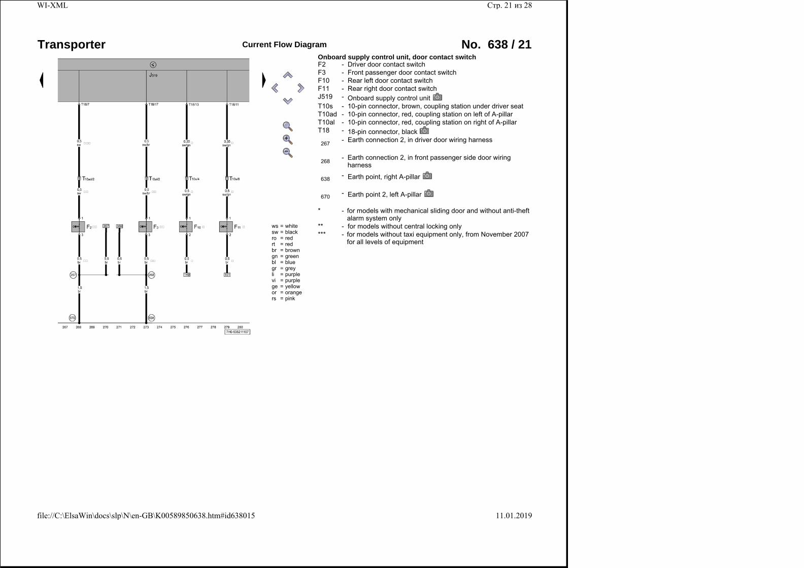
Onboard supply control unit, door contact switch F2 - Driver door contact switchF3 - Front passenger door contact switchF10 - Rear left door contact switchF11 - Rear right door contact switchJ519 - Onboard supply control unitT10s - 10-pin connector, brown, coupling station under driver seatT10ad - 10-pin connector, red, coupling station on left of A-pillarT10al - 10-pin connector, red, coupling station on right of A-pillarT18 - 18-pin connector, black
267 - Earth connection 2, in driver door wiring harness
268 -
Earth connection 2, in front passenger side door wiring harness
638 - Earth point, right A-pillar
670 - Earth point 2, left A-pillar
* - for models with mechanical sliding door and without anti-theft alarm system only
** - for models without central locking only*** -
for models without taxi equipment only, from November 2007 for all levels of equipment
Стр. 21 из 28WI-XML
11.01.2019file://C:\ElsaWin\docs\slp\N\en-GB\K00589850638.htm#id638015
Transporter Current Flow Diagram No. 638 / 22
ws = whitesw = blackro = redrt = redbr = browngn = greenbl = bluegr = greyli = purplevi = purplege = yellowor = orangers = pink
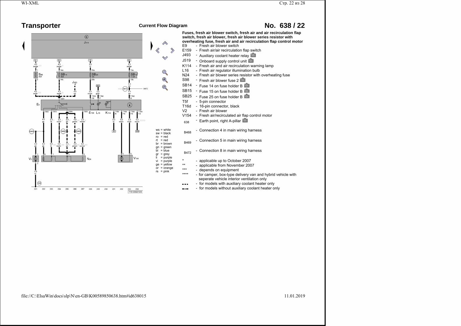
Fuses, fresh air blower switch, fresh air and air recirculation flap switch, fresh air blower, fresh air blower series resistor with overheating fuse, fresh air and air recirculation flap control motor E9 - Fresh air blower switchE159 - Fresh air/air recirculation flap switchJ493 - Auxiliary coolant heater relayJ519 - Onboard supply control unitK114 - Fresh air and air recirculation warning lampL16 - Fresh air regulator illumination bulbN24 - Fresh air blower series resistor with overheating fuseS98 - Fresh air blower fuse 2SB14 - Fuse 14 on fuse holder BSB15 - Fuse 15 on fuse holder BSB25 - Fuse 25 on fuse holder BT5f - 5-pin connectorT16d - 16-pin connector, blackV2 - Fresh air blowerV154 - Fresh air/recirculated air flap control motor
638 - Earth point, right A-pillar
B468 - Connection 4 in main wiring harness
B469 - Connection 5 in main wiring harness
B472 - Connection 8 in main wiring harness
* - applicable up to October 2007** - applicable from November 2007*** - depends on equipment**** -
for camper, box-type delivery van and hybrid vehicle with seperate vehicle interior ventilation only
- for models with auxiliary coolant heater only - for models without auxiliary coolant heater only
Стр. 22 из 28WI-XML
11.01.2019file://C:\ElsaWin\docs\slp\N\en-GB\K00589850638.htm#id638015
Transporter Current Flow Diagram No. 638 / 23
ws = whitesw = blackro = redrt = redbr = browngn = greenbl = bluegr = greyli = purplevi = purplege = yellowor = orangers = pink
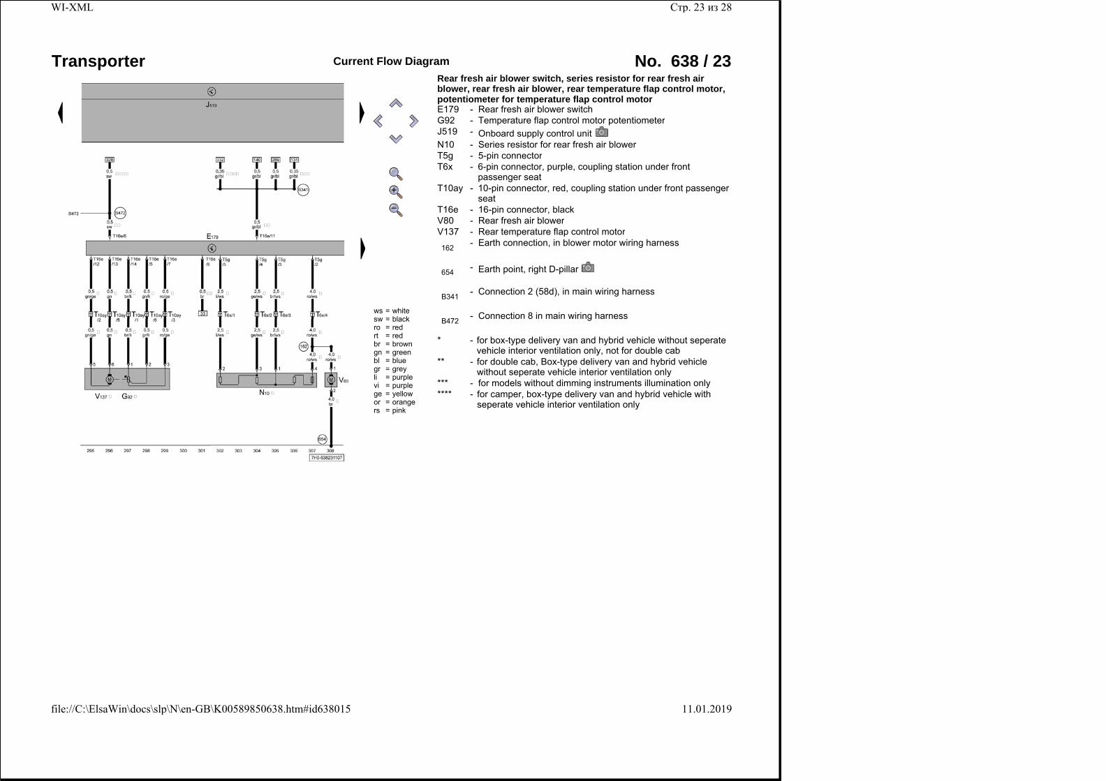
Rear fresh air blower switch, series resistor for rear fresh air blower, rear fresh air blower, rear temperature flap control motor, potentiometer for temperature flap control motor E179 - Rear fresh air blower switchG92 - Temperature flap control motor potentiometerJ519 - Onboard supply control unitN10 - Series resistor for rear fresh air blowerT5g - 5-pin connectorT6x -
6-pin connector, purple, coupling station under front passenger seat
T10ay -
10-pin connector, red, coupling station under front passenger seat
T16e - 16-pin connector, blackV80 - Rear fresh air blowerV137 - Rear temperature flap control motor
162 - Earth connection, in blower motor wiring harness
654 - Earth point, right D-pillar
B341 - Connection 2 (58d), in main wiring harness
B472 - Connection 8 in main wiring harness
* - for box-type delivery van and hybrid vehicle without seperate vehicle interior ventilation only, not for double cab
** - for double cab, Box-type delivery van and hybrid vehicle without seperate vehicle interior ventilation only
*** - for models without dimming instruments illumination only**** -
for camper, box-type delivery van and hybrid vehicle with seperate vehicle interior ventilation only
Стр. 23 из 28WI-XML
11.01.2019file://C:\ElsaWin\docs\slp\N\en-GB\K00589850638.htm#id638015
Transporter Current Flow Diagram No. 638 / 24
ws = whitesw = blackro = redrt = redbr = browngn = greenbl = bluegr = greyli = purplevi = purplege = yellowor = orangers = pink
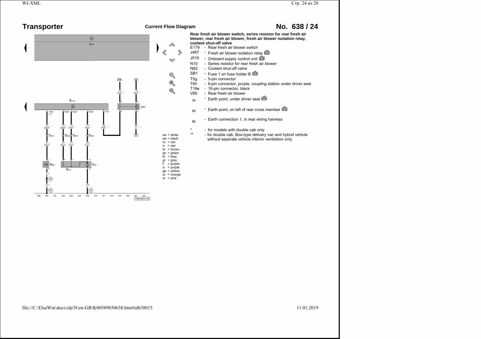
Rear fresh air blower switch, series resistor for rear fresh air blower, rear fresh air blower, fresh air blower isolation relay, coolant shut-off valve E179 - Rear fresh air blower switchJ487 - Fresh air blower isolation relayJ519 - Onboard supply control unitN10 - Series resistor for rear fresh air blowerN82 - Coolant shut-off valveSB1 - Fuse 1 on fuse holder BT5g - 5-pin connectorT6h - 6-pin connector, purple, coupling station under driver seatT16e - 16-pin connector, blackV80 - Rear fresh air blower
34 - Earth point, under driver seat
68 - Earth point, on left of rear cross member
86 - Earth connection 1, in rear wiring harness
* - for models with double cab only** -
for double cab, Box-type delivery van and hybrid vehicle without seperate vehicle interior ventilation only
Стр. 24 из 28WI-XML
11.01.2019file://C:\ElsaWin\docs\slp\N\en-GB\K00589850638.htm#id638015
Transporter Current Flow Diagram No. 638 / 25
ws = whitesw = blackro = redrt = redbr = browngn = greenbl = bluegr = greyli = purplevi = purplege = yellowor = orangers = pink
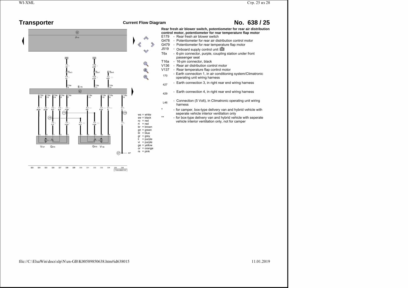
Rear fresh air blower switch, potentiometer for rear air distribution control motor, potentiometer for rear temperature flap motor E179 - Rear fresh air blower switchG478 - Potentiometer for rear air distribution control motorG479 - Potentiometer for rear temperature flap motorJ519 - Onboard supply control unitT6x -
6-pin connector, purple, coupling station under front passenger seat
T16a - 16-pin connector, blackV136 - Rear air distribution control motorV137 - Rear temperature flap control motor
170 - Earth connection 1, in air conditioning system/Climatronic operating unit wiring harness
427 - Earth connection 3, in right rear end wiring harness
429 - Earth connection 4, in right rear end wiring harness
L46 -
Connection (5 Volt), in Climatronic operating unit wiring harness
* - for camper, box-type delivery van and hybrid vehicle with seperate vehicle interior ventilation only
** - for box-type delivery van and hybrid vehicle with seperate vehicle interior ventilation only, not for camper
Стр. 25 из 28WI-XML
11.01.2019file://C:\ElsaWin\docs\slp\N\en-GB\K00589850638.htm#id638015
Transporter Current Flow Diagram No. 638 / 26
ws = whitesw = blackro = redrt = redbr = browngn = greenbl = bluegr = greyli = purplevi = purplege = yellowor = orangers = pink
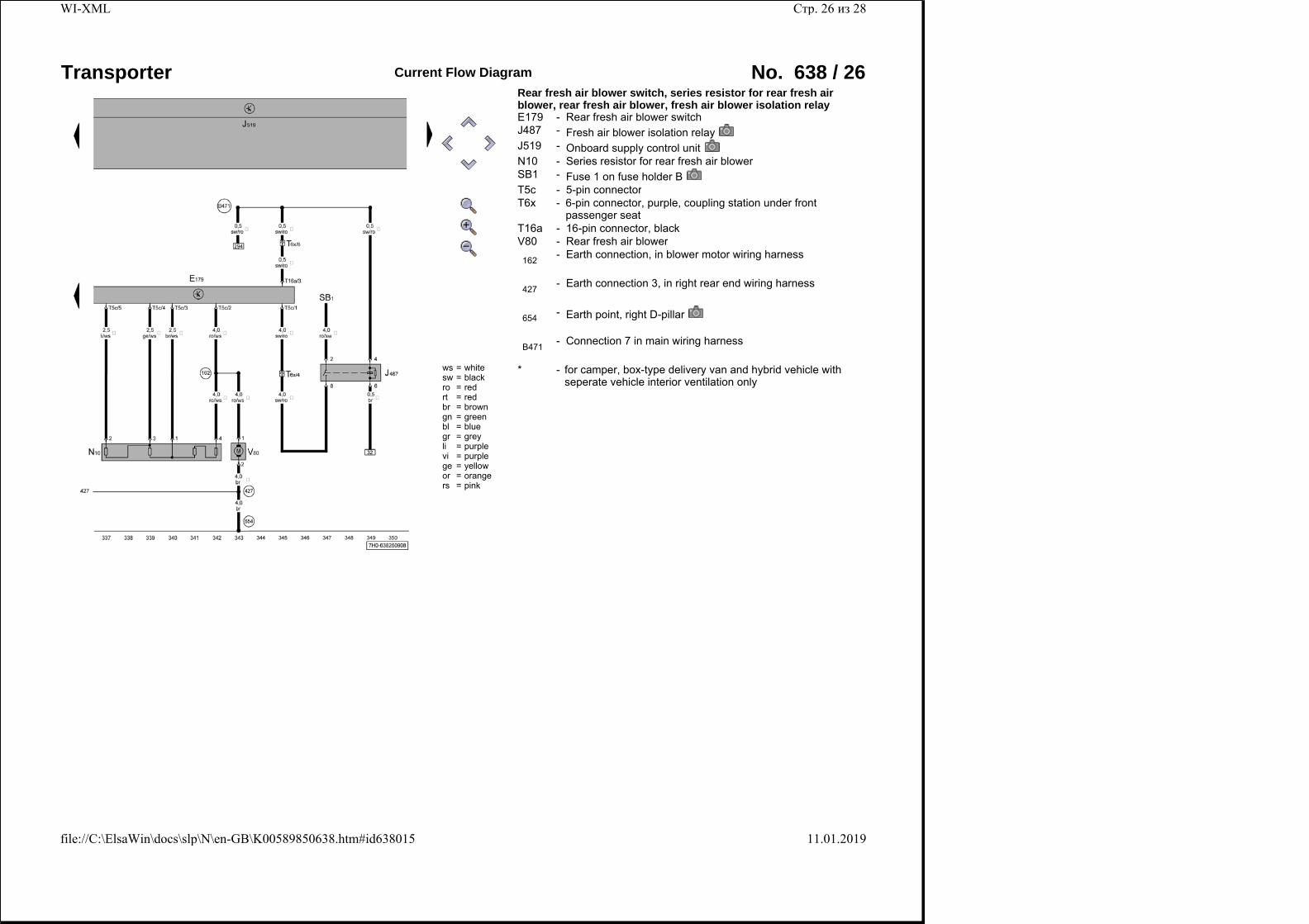
Rear fresh air blower switch, series resistor for rear fresh air blower, rear fresh air blower, fresh air blower isolation relay E179 - Rear fresh air blower switchJ487 - Fresh air blower isolation relayJ519 - Onboard supply control unitN10 - Series resistor for rear fresh air blowerSB1 - Fuse 1 on fuse holder BT5c - 5-pin connectorT6x -
6-pin connector, purple, coupling station under front passenger seat
T16a - 16-pin connector, blackV80 - Rear fresh air blower
162 - Earth connection, in blower motor wiring harness
427 - Earth connection 3, in right rear end wiring harness
654 - Earth point, right D-pillar
B471 - Connection 7 in main wiring harness
* - for camper, box-type delivery van and hybrid vehicle with seperate vehicle interior ventilation only
Стр. 26 из 28WI-XML
11.01.2019file://C:\ElsaWin\docs\slp\N\en-GB\K00589850638.htm#id638015
Transporter Current Flow Diagram No. 638 / 27
ws = whitesw = blackro = redrt = redbr = browngn = greenbl = bluegr = greyli = purplevi = purplege = yellowor = orangers = pink
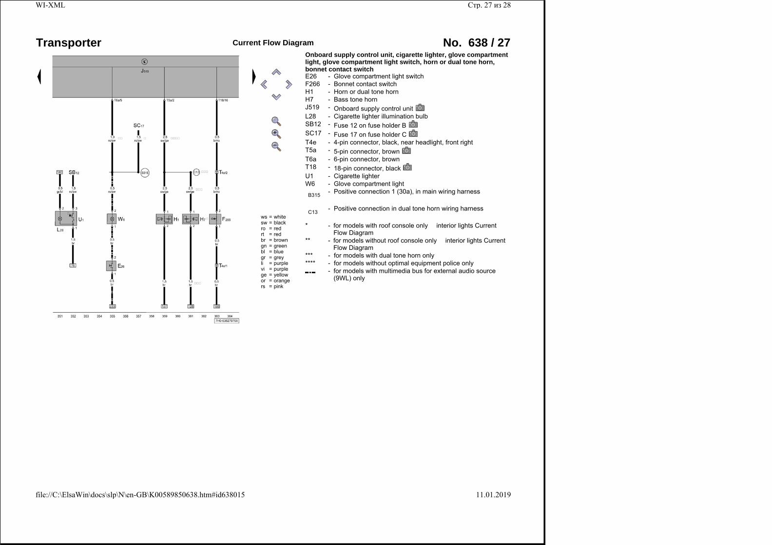
Onboard supply control unit, cigarette lighter, glove compartment light, glove compartment light switch, horn or dual tone horn, bonnet contact switch E26 - Glove compartment light switchF266 - Bonnet contact switchH1 - Horn or dual tone hornH7 - Bass tone hornJ519 - Onboard supply control unitL28 - Cigarette lighter illumination bulbSB12 - Fuse 12 on fuse holder BSC17 - Fuse 17 on fuse holder CT4e - 4-pin connector, black, near headlight, front rightT5a - 5-pin connector, brownT6a - 6-pin connector, brownT18 - 18-pin connector, blackU1 - Cigarette lighterW6 - Glove compartment light
B315 - Positive connection 1 (30a), in main wiring harness
C13 - Positive connection in dual tone horn wiring harness
* -
for models with roof console only � interior lights Current Flow Diagram
** - for models without roof console only � interior lights Current Flow Diagram
*** - for models with dual tone horn only**** - for models without optimal equipment police only
-
for models with multimedia bus for external audio source (9WL) only
Стр. 27 из 28WI-XML
11.01.2019file://C:\ElsaWin\docs\slp\N\en-GB\K00589850638.htm#id638015
Transporter Current Flow Diagram No. 638 / 28
ws = whitesw = blackro = redrt = redbr = browngn = greenbl = bluegr = greyli = purplevi = purplege = yellowor = orangers = pink
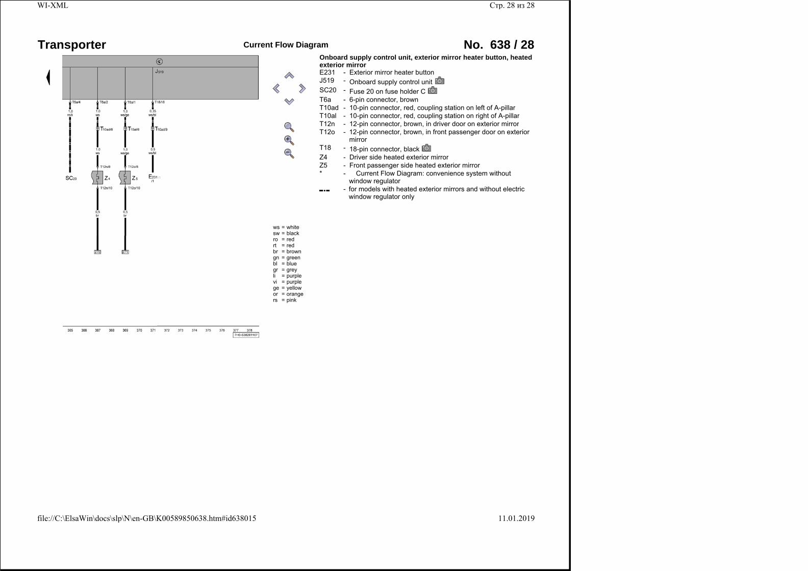
Onboard supply control unit, exterior mirror heater button, heated exterior mirror E231 - Exterior mirror heater buttonJ519 - Onboard supply control unitSC20 - Fuse 20 on fuse holder CT6a - 6-pin connector, brownT10ad - 10-pin connector, red, coupling station on left of A-pillarT10al - 10-pin connector, red, coupling station on right of A-pillarT12n - 12-pin connector, brown, in driver door on exterior mirrorT12o -
12-pin connector, brown, in front passenger door on exterior mirror
T18 - 18-pin connector, blackZ4 - Driver side heated exterior mirrorZ5 - Front passenger side heated exterior mirror* -
� Current Flow Diagram: convenience system without window regulator
- for models with heated exterior mirrors and without electric window regulator only
Стр. 28 из 28WI-XML
11.01.2019file://C:\ElsaWin\docs\slp\N\en-GB\K00589850638.htm#id638015