trek diamant super commuter+ super commuter+ 8/ 9/ 8s/ 9s ... 3.10.1 routing of the front brake...
TRANSCRIPT

TrekSuper Commuter+
DiamantZouma+
Dealer Service Information
2017


1
Trek Super Commuter+ 8/ 9/ 8S/ 9SDiamant Zouma+ (/S /Elite /Elite S)
Table of Contents1. Overview bicycle configurations .....................................................................................................................................................................3
2. Walk around ..........................................................................................................................................................................................................42.1 Show view – Colors and drive systems ..................................................................................................................................................42.2 Front/Rear view ...........................................................................................................................................................................................52.3 Side view ........................................................................................................................................................................................................52.4 Cockpit ...........................................................................................................................................................................................................6
3. Technical details ...................................................................................................................................................................................................73.1 Frame 7
3.1.1 Frame sizes ........................................................................................................................................................................................73.1.2 Use Condition ...................................................................................................................................................................................73.1.3 Drop-outs ..........................................................................................................................................................................................7
3.2 Specific parts ................................................................................................................................................................................................73.2.1 Specific parts - overview .................................................................................................................................................................73.2.2 Specific parts – photos ....................................................................................................................................................................8
3.3 Model and sales region specific components ......................................................................................................................................93.3.1 Configuration depending parts - overview ...................................................................................................................................93.3.2 Configuration depending parts - photos .....................................................................................................................................10
3.4 Additional parts on 45 km/h EU-models ............................................................................................................................................. 113.4.1 Additional parts on 45 km/h EU-models - overview ................................................................................................................ 113.4.2 Additional parts on 45 km/h EU-models – photos ................................................................................................................... 12
3.5 Bosch eBike Assist system ...................................................................................................................................................................... 123.5.1 Bosch eBike Assist system - overview ......................................................................................................................................... 133.5.2 Bosch eBike Assist system – photos ............................................................................................................................................ 13
3.6 Drive train .................................................................................................................................................................................................... 143.7 Brake system ............................................................................................................................................................................................... 14
3.7.1 Brake system – overview ............................................................................................................................................................... 143.7.2 Brake system – details ................................................................................................................................................................... 14
3.8 Fenders ......................................................................................................................................................................................................... 143.8.1 Front fender attachment ............................................................................................................................................................... 143.8.2 Rear fender attachment ................................................................................................................................................................ 15
3.9 Rear rack ...................................................................................................................................................................................................... 163.9.1 Rack – design and application ...................................................................................................................................................... 163.9.2 Rack – maximum allowed load .................................................................................................................................................... 16
3.10 Cable routing .............................................................................................................................................................................................. 163.10.1 Routing of the front brake cable at the fork ............................................................................................................................... 163.10.2 Routing of the rear brake and shifter cables .............................................................................................................................. 173.10.3 Routing of electrical wiring to the front of the bicycle .............................................................................................................. 173.10.4 Routing of electrical wiring to the rear of the bicycle ............................................................................................................... 173.10.5 Cable routing – photos .................................................................................................................................................................. 183.10.6 Cable routing – technical drawings ............................................................................................................................................. 19
3.11 Tires ..............................................................................................................................................................................................................223.11.1 Tire size ............................................................................................................................................................................................223.11.2 Tire pressure ...................................................................................................................................................................................223.11.3 Tires specifications .........................................................................................................................................................................22
4. Electrical specifications ...................................................................................................................................................................................234.1 Light configurations ..................................................................................................................................................................................23
4.1.1 Lights on EU 25 km/h models ......................................................................................................................................................234.1.2 Lights on US 28 mph models .......................................................................................................................................................234.1.3 Lights on 45 km/h models with EU-Type Approval ..................................................................................................................234.1.4 Lights – photos .............................................................................................................................................................................. 24

2
4.2 Electric diagram of lights ........................................................................................................................................................................ 254.2.1 Electric diagram of lights on non EU-Type Approval bicycles ................................................................................................. 254.2.2 Electric diagram of lights on EU-Type Approval bicycles ........................................................................................................ 264.2.3 Electrical connections to the Bosch drive unit ............................................................................................................................27
5. Operating instructions .................................................................................................................................................................................... 285.1 Charging the battery ................................................................................................................................................................................ 285.2 Battery removal/installation .................................................................................................................................................................. 28
5.2.1 Battery removal ............................................................................................................................................................................. 285.2.2 Battery installation ....................................................................................................................................................................... 29
5.3 Operating the Bosch eBike assist system ........................................................................................................................................... 295.4 Switching the lights On/Of .................................................................................................................................................................... 29
5.4.1 Switching the lights On/Off on Non – EU-Type Approval bicycles........................................................................................ 295.4.2 Switching the lights On/Off on models with EU-Type Approval ........................................................................................... 30
5.5 Panniers ....................................................................................................................................................................................................... 30
6. Bicycle specific maintenance......................................................................................................................................................................... 306.1 Battery rail ................................................................................................................................................................................................... 31
6.1.1 Adjusting the battery rail position ............................................................................................................................................... 316.1.2 Replacing the battery rail ..............................................................................................................................................................32
6.2 Replacing the battery lock .......................................................................................................................................................................336.3 Replacing the battery docking ............................................................................................................................................................... 346.4 Drop-out mounting ...................................................................................................................................................................................356.5 Replacing the front fender ...................................................................................................................................................................... 366.6 Replacing the rear fender ....................................................................................................................................................................... 36
6.6.1 Needed tools and parts ................................................................................................................................................................ 366.6.2 Removing the old fender and the components ..........................................................................................................................376.6.3 Marking holes on the replacement fender................................................................................................................................. 386.6.4 Drilling holes in the replacement fender .................................................................................................................................... 386.6.5 Mounting the new fender ............................................................................................................................................................ 39
6.7 Rack mounting .......................................................................................................................................................................................... 396.8 Mounting the drive unit ..........................................................................................................................................................................40
6.8.1 Replacing the drive unit................................................................................................................................................................406.8.2 Drive unit mounting - technical drawing .................................................................................................................................... 41
7. Spare parts .......................................................................................................................................................................................................... 427.1 Spare parts - bicycle ................................................................................................................................................................................ 427.2 Spare parts - Bosch eBike System ........................................................................................................................................................ 437.3 Disposal ...................................................................................................................................................................................................... 43
7.3.1 Disposal of electrical components .............................................................................................................................................. 437.3.2 Disposal of batteries ..................................................................................................................................................................... 43
8. RIDE+ Owner’s manuals .................................................................................................................................................................................448.1 RIDE+ Owner’s manuals - content and languages...........................................................................................................................44
8.1.1 RIDE+ Owner’s manual for bicycles sold in Europe..................................................................................................................448.1.2 RIDE+ Owner’s manual for bicycles sold in the US ..................................................................................................................44
8.2 RIDE+ Owner’s manuals - overview MY2017 ...................................................................................................................................44

3
1. Overview bicycle configurations
The bicycles with the Trek ‘SC-frame’ are available in these configurations, depending on region:
Model GearMaximum speed
EU - Type Approval Region
Diamant Zouma+ 11 speed derailleur 25 km/h No Germany, Austria, Switzerland
Zouma Elite+ NuVinci N380 SE 25 km/h No Germany, Austria, Switzerland
Zouma+ S 11 speed derailleur 45 km/h Yes Germany, Austria, Switzerland
Zouma Elite+ S NuVinci N380 SE 45 km/h Yes Germany, Austria, Switzerland
Trek Super Commuter+ 8 11 speed derailleur 25 km/h No EU
Super Commuter+ 9 NuVinci N380 SE 25 km/h No EU
Super Commuter+ 8S 11 speed derailleur 45 km/h Yes EU
Super Commuter+ 9S NuVinci N380 SE 45 km/h Yes EU
Super Commuter+ 8S 11 speed derailleur 28 mph No US/Canada

4
2. Walk around
2.1 Show view – Colors and drive systems
Trek Diamant
IGH IGH
Super Commuter 9 - 9S Diamant Zouma Elite+ (S)
Derailleur Derailleur
Super Commuter 8 - 8S Diamant Zouma+ (S)

5
2.2 Front/Rear view
Front view Rear view
* Note. Type of front/taillight and presence of the mirror is depending on the bicycles’ configuration and region.
2.3 Side view
Side view (IGH)

6
Side view (Derailleur)
2.4 Cockpit
Variant with Bosch Purion display and IGH shifter
Variant with Bosch Purion display and derailleur shifter
Notes.• The mirror is mandatory for Speed Pedelecs in Europe according to the European Type Approval
(position: above handlebar).
• The high beam light switch is only present on bicycles with the Supernova M99 Pro head light.
7
3. Technical details
3.1 Frame
The bicycles are equipped with a specially designed frame for a center Bosch drive unit and have a semi integrated battery pack. The frames are adapted to accommodate the brake and shifter cables and electric wiring inside. The bicycle frames comply with the ISO 4210 norm.
3.1.1 Frame sizes
The Trek Super Commuter+ and Diamant Zouma+ bicycles are available in four frame sizes: 45, 50, 55 and 60cm. The frame sizing is virtual. As virtual size, the actual seat tube length is 5cm shorter, to create a better stand over.
3.1.2 Use Condition
There are many types of bicycles, and each is designed for a specific Use Condition.
This bicycle is designed for Use Condition 1; “Riding on a paved surface where the tires are always on the ground”.
• The total weight limit (rider and luggage) for this bicycle is 136kg / 300lb.• The maximum weight of the rider is 125kg / 275lb). • The maximum allowed load on the rack is 7,5kg / 16,5lb per side; in total 15kg / 33lb.
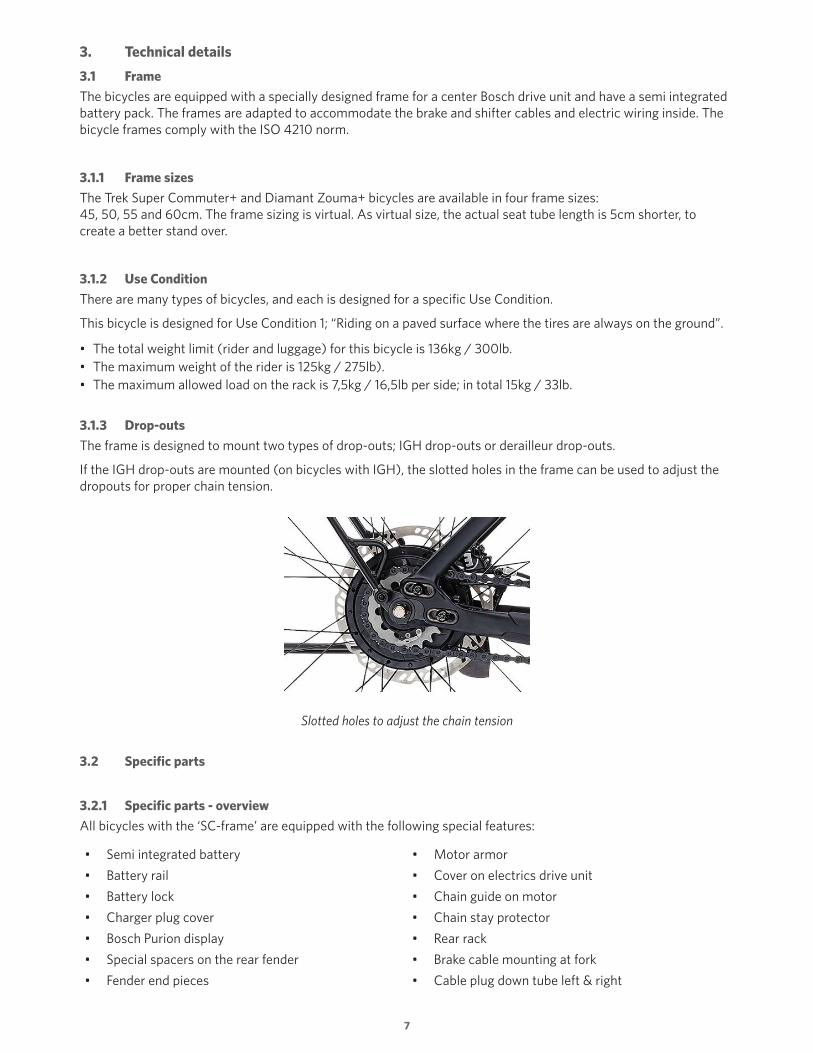
3.1.3 Drop-outs
The frame is designed to mount two types of drop-outs; IGH drop-outs or derailleur drop-outs.
If the IGH drop-outs are mounted (on bicycles with IGH), the slotted holes in the frame can be used to adjust the dropouts for proper chain tension.
Slotted holes to adjust the chain tension
3.2 Specific parts
3.2.1 Specific parts - overview
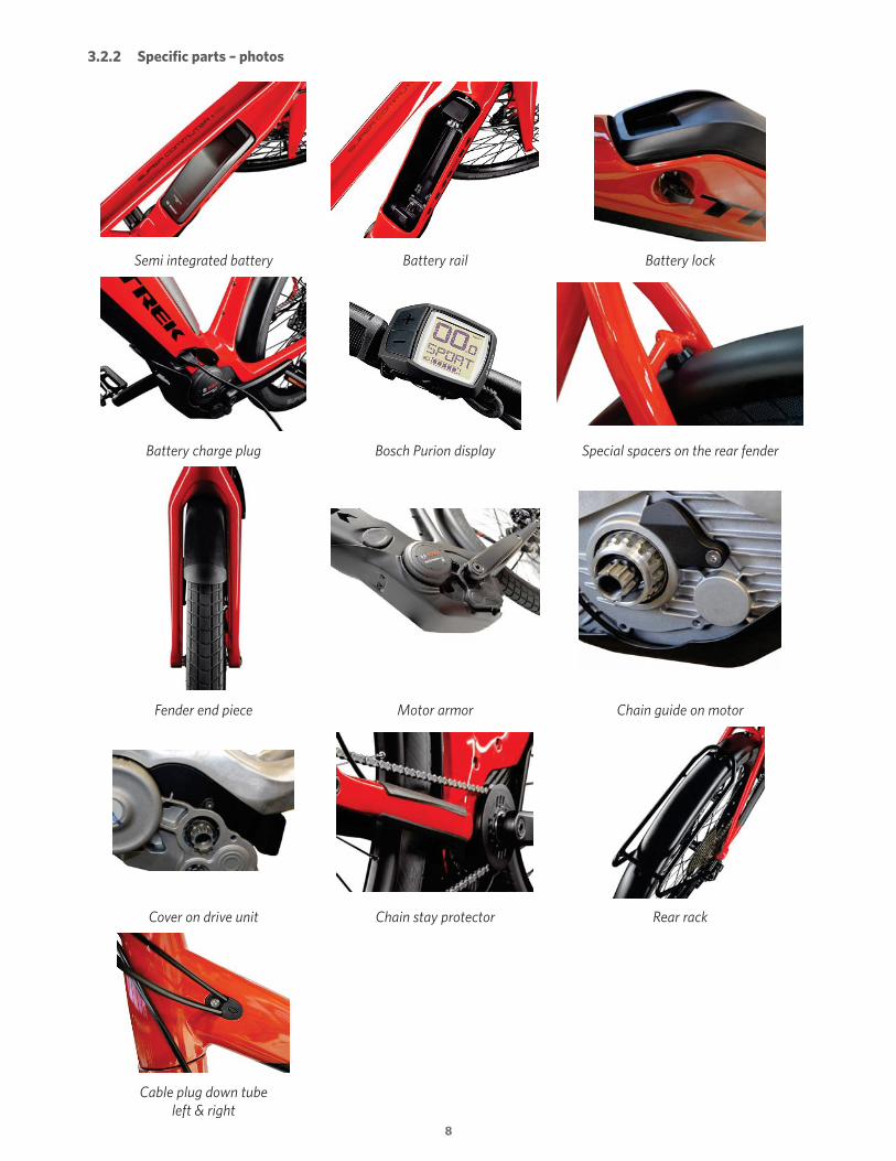
All bicycles with the ‘SC-frame’ are equipped with the following special features:
• Semi integrated battery • Motor armor
• Battery rail • Cover on electrics drive unit
• Battery lock • Chain guide on motor
• Charger plug cover • Chain stay protector
• Bosch Purion display • Rear rack
• Special spacers on the rear fender • Brake cable mounting at fork
• Fender end pieces • Cable plug down tube left & right
8
3.2.2 Specific parts – photos
Semi integrated battery Battery rail Battery lock
Battery charge plug Bosch Purion display Special spacers on the rear fender
Fender end piece Motor armor Chain guide on motor
Cover on drive unit Chain stay protector Rear rack
Cable plug down tube left & right

9
3.3 Model and sales region specific components
3.3.1 Configuration depending parts - overview
Depending on the configuration and region, the bicycles are equipped with a selection of these parts:
• Front light: • Rear derailleur protector* Supernova E3 Mini2 • Rear hub: Supernova M99 Pure+ 11 speed rear derailleur
Supernova M99 Pro (daytime running light, low beam and high beam
NuVinci N380 SE gear hub
• Shifter:
• Taillight: Shimano trigger shifter
Supernova E3 NuVinci roller shifter
Supernova M99 (with built-in brake light and license plate light) *On bicycles with rear derailleur.

10
3.3.2 Configuration depending parts - photos
Supernova E3 Mini2 Supernova M99 Pure+ Supernova M99 Pro
Supernova E3 taillight + rear reflector
Supernova M99 taillight + rear reflector
Derailleur protector
11 speed derailleur NuVinci N380 SE
Shimano trigger shifter NuVinci roller shifter Cable mounting on chain stay Derailleur (A)/ IGH (B)

11
3.4 Additional parts on 45 km/h EU-models
3.4.1 Additional parts on 45 km/h EU-models - overview
The 45 km/h fast electric bicycle EU-models comply with EU-Type Approval (e1-2002-24-0727-00) for MY2017 and to this aim are additionally equipped with the following bicycle parts*:
• Front light with daytime running light and high beam
• Brake light switches on both brake levers
• Speed bicycle brake levers
• Light switch (for high beam) • Rear view mirror (position: above handlebar)
• LED rear light with built-in brake light and license plate light
• Side reflectors
• A unique VIN number per bicycle
• Adjustable license plate holder
* These additional parts are all part of the EU Type Approval. It is not allowed to remove or exchange them for other (non-certified) equipment. This also applies to the fork, tires, brakes, kickstand, motor, battery pack and display.

12
3.4.2 Additional parts on 45 km/h EU-models – photos
Front light Supernova M99 Pro High beam switch Rear light, including brake light and license plate light
License plate holder Lever blades with ball-end (including brake light switch)
Mirror (position: above handlebar)
Side reflectors A unique VIN number per SC-frame
3.5 Bosch eBike Assist system
All bicycles are equipped with the Bosch ‘Performance Line’ assist system. The exact configuration of the kit depends on the region of sale. This also determines the specific firmware and thus the maximum allowed assist speed and also speed indication (km/h or mph). Depending on the configuration and region, the Bosch drive unit can assist up to 20 mph, 25 km/h, 28 mph or 45 km/h.
Refer to chapter 1 for all configurations of the Trek and Diamant models.
The drive unit is built into the middle of the specially designed frame. The frame has a semi integrated battery pack and battery rail. The battery can be charged on the bicycle or can be taken from the bicycle to be charged elsewhere.

13
3.5.1 Bosch eBike Assist system - overview
Bosch Part Description 25 km/h (Bosch P/N:) 45 km/h - 28 mph (Bosch P/N:)
Drive unit Performance Line 0 275 007 037 (CX) 0275.007.041 (Speed, 45 km/h -28 mph)
Display Purion 1270.020.917 1270.020.917 (km/h or mph on display)
Battery pack Down tube, 500 Wh 0275.007.530 0275.007.530 (EU)0275.007.533/534 (US)
Charger Standard 4A 0275.007.907 0275.007.907
Bosch eBike Assist System parts
3.5.2 Bosch eBike Assist system – photos
Performance Line drive unit Purion display Integrated down-tube battery
Charge plug Standard charger

14
3.6 Drive train
The Super Commuter+ and Diamant Zouma+ bicycles are available either with IGH or 11 speed rear derailleur gear systems. Consequently, the shifter on the handle bar is a IGH shifter or an rear derailleur shifter. From the IGH shifter, two operating cables run through the frame to the hub, the rear derailleur shifter has one operating cable routed to the rear derailleur.
3.7 Brake system
3.7.1 Brake system – overview
Model Brake systemMaximum speed Remarks Region
Diamant Zouma+ Shimano M615 hydraulic brake system
25 km/h - Germany, Austria, Switzerland
Zouma Elite+ Magura MT4/MT5 hydraulic brake system
25 km/h - Germany, Austria, Switzerland
Zouma+ S Zouma Elite+ S
Magura MT5e hydraulic brake system
45 km/h EU-Type Approval,eBall brake levers with brake switch
Germany, Austria, Switzerland
Trek Super Commuter+ 8 Shimano M615 hydraulic brake system
25 km/h - EU
Super Commuter+ 9 Magura MT4/MT5 hydraulic brake system
25 km/h - EU
Super Commuter+ 8S Shimano M615 hydraulic brake system
28 mph - US/Canada
Super Commuter+ 8SSuper Commuter+ 9S
Magura MT5e hydraulic brake system
45 km/h EU-Type Approval,eBall brake levers with brake switch
EU
3.7.2 Brake system – details
All bicycles are equipped with a hydraulic brake system and have a 180mm brake disc on front and rear hub. The EU-bicycles with Type Approval have built-in electric brake switches at both left and right hand brake levers that activate the brake light.
3.8 Fenders
3.8.1 Front fender attachment
The front fender is directly mounted to the fork. On the top, the fender is mounted to the fork crown, with a thin spacer between fender and fork crown. The other side of the fender is secured to the fork with a specially designed fender stay. The front fender has a fender end piece at both ends.
Front fender and fender end piece (at both ends)

15
3.8.2 Rear fender attachment
The rear fender is directly mounted to the frame at the seat stay bridge and at the chain stay bridge (near motor mount), with a spacer between fender and frame. At the rear it is connected to the dropouts by the rear rack. The default spacers are 10mm thick at the motor mount and 5mm thick at the seat stay bridge (with the drop-outs in the middle position). The spacer applied at the lower position may vary in thickness (or even be left out), as the fender will move with the adjustment of the dropouts. Consequently, depending on the position of the drop-outs, the distance between frame and fender can change as well. The rear fender is an integrated part of the rear rack mounting, it acts as a rack stay. The rear fender has a fender end piece at the rear and has a channel for the electric wiring to the rear light(s).
Note. Rear fenders are drilled size-specific; the location of the holes varies per frame size.
The rear fender is mounted to the rack and the frame Fender end piece
The lower spacer may vary in thickness (0mm to 10mm) The top spacer (5mm)

16
3.9 Rear rack
3.9.1 Rack – design and application
The rear rack is designed to carry a pannier on both sides. The rack has a stop at each side to prevent the panniers sliding back and forth.
The rack is designed to support the fender – it is an integrated part, together with the drop-outs, of the rear part of the bicycle.
The rack as an integrated part of the rear end Slide stoppers
The rear fender end piece
3.9.2 Rack – maximum allowed load
The maximum allowed load on the rack is 7,5kg / 16,5lb per side; in total 15kg / 33lb.
3.10 Cable routing
3.10.1 Routing of the front brake cable at the fork
At the fork, a brake cable is led to the front brake caliper. It is secured to the fork with one (or two; depending on the bicycles’ configuration) fasteners to prevent damage to the brake cable and paint of the fork.

17
3.10.2 Routing of the rear brake and shifter cables
All cables to the back of the bicycle run through the frame. On each side of the down tube, the brake, shifter and electrical cables enter the frame via an opening in the frame. From there, the cables run via the battery bay to the back of the frame.
In the battery bay, the cables are secured to both sides of the battery rail spacers with help of tie-wraps.
The brake cable is led through the left hand chain stay to the rear brake caliper.
The shifter cable(s) run along the drive unit and chain stay to the derailleur or IGH. These cables are firmly secured to the drive unit and chain stay with specially designed clips.
There are two types of clips available; one to secure the single cable of a derailleur drive system, the other to secure the twin cables of the IGH.
3.10.3 Routing of electrical wiring to the front of the bicycle
The electric wiring to the front of the bicycle consists of wiring to power the front light and to the brake switches (if applicable, depending on configuration). The wires enter the frame via an opening in the frame and run via the battery bay to the drive unit, along the cables of rear brake and shifter.
All cables running through the battery bay are secured to the battery rail spacers with tie-wraps, on both sides. The electrical connections at the drive unit are protected by a specially designed cover that fits between drive unit and frame.
3.10.4 Routing of electrical wiring to the rear of the bicycle
The electric wiring to the rear of the bicycle consists of wiring to the rear light and, if applicable, the brake light and license plate lighting. Also the cable from the speed sensor is part of the rear wiring.
The wire for the lighting is led through the rear fender. The fender has a built-in channel to hide and protect the wiring. Four clips secure the wire in the channel (ensure to fit the flat side of the clip pointing to the wiring cable). At the front end, the wiring enters the motor cover, and is routed to the electrical connection at the drive unit. The speed sensor cable runs through the non-drive side stay, via an opening in the stay, to the speed sensor. The opening is covered with a specially designed frame plug. The connector of the speed sensor is connected to the drive unit.

18
3.10.5 Cable routing – photos
Front frame entry (both sides) Rear brake, shifter and electrical cables through the battery bay
Cable(s) at drive unit Top: Cable at chain stay (derailleur)
Bottom: Cables at chain stay (IGH)
Front brake cable mounted at the fork Rear light cable, secured with a clip, in the fender guide
Rear light cable routed to drive unit

19
3.10.6 Cable routing – technical drawings
Legend: Yellow = Electrical, Blue = Shifting, Red = Brake, Green = Speed sensor
Cable routing through the down tube

20
Cable routing from handle bar to down tube Cable routing near drive unit
Cable routing chain stay and seat stay
Cable routing to rear light

21
Cable routing through the frame
1. Drive side: electrical cable (3x) Non-drive side: rear brake and shifter cable(s)
2. Cable guide frame plug
3. Cable guide clamp for front brake hose
4. Rear light cable through rear fender
5. Cable guide frame plug
6. Cable clamp for derailleur (1 cable) or IGH (2 cables)
7. Rear light cable entering the motor mount
8. Cable clamp for derailleur (1 cable) or IGH (2 cables)
9. Chain stay guard
22
3.11 Tires
3.11.1 Tire size
The recommended tire size is 62-584 / 27.5x2.40-650b. This is also the maximum tire size.
3.11.2 Tire pressure
For the recommended type pressure of tires, refer to the specification on the sidewall of the tire.
3.11.3 Tires specifications
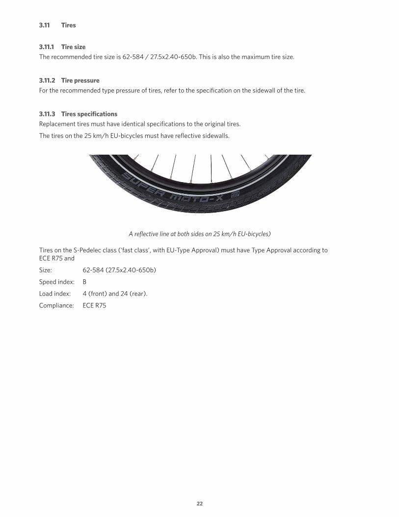
Replacement tires must have identical specifications to the original tires.
The tires on the 25 km/h EU-bicycles must have reflective sidewalls.
A reflective line at both sides on 25 km/h EU-bicycles)
Tires on the S-Pedelec class (‘fast class’, with EU-Type Approval) must have Type Approval according to ECE R75 and
Size: 62-584 (27.5x2.40-650b)
Speed index: B
Load index: 4 (front) and 24 (rear).
Compliance: ECE R75

23
4. Electrical specifications
4.1 Light configurations
The lighting equipment on the bicycles depends on region and maximum allowed speed of the bicycles. EU-Type Approval bicycles have lighting that comply with EU-laws.
The wire harnesses differ in detail.
4.1.1 Lights on EU 25 km/h models
Front light: Supernova E3 Mini2 (12V)
Rear light: Supernova E3 Taillight (12V)
Power source: The front light connects to the 12V front light port on the Bosch drive unit and the rear light connects to the rear light port on the Bosch drive unit, with use of Bosch light connectors and cables.
Specifics: No brake light, no brake switches and no high beam.
Refer to paragraph 4.2.1 for the electric diagram.
4.1.2 Lights on US 28 mph models
Front light: Supernova M99 Pure+ (12V)
Rear light: Supernova E3 Taillight (12V)
Power source: The front light connects to the 12V front light port on the Bosch drive unit and the rear light connects to the rear light port on the Bosch drive unit, with use of Bosch light connectors and cables.
Specifics: No brake light, no brake switches and no high beam.
Refer to paragraph 4.2.1 for the electric diagram.
4.1.3 Lights on 45 km/h models with EU-Type Approval
Front light: Supernova M99 Pro (12V)
Rear light: Supernova M99 Taillight (12V)
Power source: Both lights run from the Bosch battery connection (by use of a Bosch “eshift” Y-cable).
Specifics: Equipped with brake light, brake switches and high beam.
Refer to paragraph 4.2.2 for the electric diagram.

24
4.1.4 Lights – photos
Supernova E3 Mini2 Supernova M99 Pure+ Supernova M99 Pro
Supernova E3 tail light Supernova M99 tail light
25
4.2 Electric diagram of lights
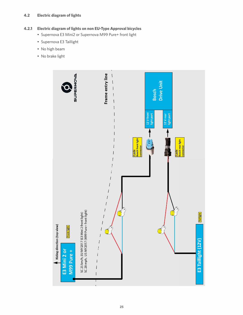
4.2.1 Electric diagram of lights on non EU-Type Approval bicycles
• Supernova E3 Mini2 or Supernova M99 Pure+ front light
• Supernova E3 Taillight
• No high beam
• No brake light

26
4.2.2 Electric diagram of lights on EU-Type Approval bicycles
• Supernova M99 Pro front light
• Supernova M99 Taillight
• Daytime running light
• High beam (operated by switch on the handle bar)
• Brake light (operated by switch on both brake levers)

27
4.2.3 Electrical connections to the Bosch drive unit
The Bosch drive unit has five positions to connect electric parts. Two of the connections are available for directly powered lighting (12 Volt, at a maximum current of 1500 mA in total, randomly distributed for both front and rear light). On 25 km/h of 28 mph bicycles, the lights can be switched On and Off on the display. On 45 km/h Speed Pedelecs, the lights are is always on; the front light can be in day light running or low beam modus, depending on the surrounding light intensity (light sensor driven).
Electrical connections at the drive unit
*Note. When the drive unit must be replaced, the replacement drive unit must be of Bosch model year 2017 or newer as older units cannot deliver 12 Volt. The default voltage on the replacement drive unit is 6 Volt. With help of the Bosch diagnose software, the voltage to power the lights must be switched to 12 Volt (the maximum current, in total, is 1500 mA).
Electrical diagram of the Bosch eBike system (with all options) *Presence of some options is depending on the bicycles’ configuration and region

28
5. Operating instructions
5.1 Charging the battery
The battery can be charged on the bicycle or can be removed from the bicycle to be charged elsewhere.
When charging on the bicycle, flip the cover of the integrated charge plug to the right (1) and connect the charger to the battery docking (2) and mains.
Refer to the RIDE+ Owner’s manual delivered with the bicycle for more details about charging.
Charging the battery on the bicycle
5.2 Battery removal/installation
5.2.1 Battery removal
To remove the battery, unlock the security lock by turning the key counterclockwise (1). The battery will spring up. Lift the battery out of the upper holder (2) and pull it out of the lower holder to remove the battery from the bicycle. The key automatically returns to the rest position.
Removing the battery

29
5.2.2 Battery installation
To place the battery in the frame, first position the battery in the lower holder (1) and press it downwards at the other side of the battery (2), until you hear the ‘click’ as the battery locks itself in the upper holder.
Remove the key to prevent theft of the battery or injuries (3).
Installing the battery
5.3 Operating the Bosch eBike assist system
For operating instructions about the Bosch eBike assist system, refer to the RIDE+ Owner’s manual of the bicycle (refer to paragraph 8.2 for an overview).
5.4 Switching the lights On/Of
5.4.1 Switching the lights On/Off on Non – EU-Type Approval bicycles
The front and rear light of these models can be switched On/Off manually on the display.
Medium-press the ‘+’ button on the Purion display to switch On the front and rear lights. To switch Off the bicycle lights, long-press the “+” button. The lighting symbol is displayed when the light is On.
Medium press the “+” button to switch On the lights

30
5.4.2 Switching the lights On/Off on models with EU-Type Approval
These models have a front light with a daytime running light, low beam and a high beam, and a rear light with an integrated license plate light. The front and rear light are always on when the system is On (even if the assist level is zero).
Depending on the darkness outside, measured by a light sensor, the front light will be in daytime running modus or low beam modus. The high beam can be switch On/Off manually by pressing the high beam switch on the handlebar once if the circumstances require extra lighting.
High beam switch on the handlebar
These models have an integrated brake light as well, operated by at least one of the two brake switches on both brake levers.
5.5 Panniers
The rear rack is designed to carry a pannier on both sides.
The rack has a stop at each side to prevent the panniers sliding back and forth.
The maximum allowed load on the rack is 7,5kg / 16,5lb per side; in total 15kg / 33lb.
6. Bicycle specific maintenance
Important notes. • In addition to the normal safety, when working on an electric bicycle, remove the battery to prevent accidental activation
of the system or electrical damage (unless instructed otherwise).• Only use genuine replacement parts for safety-critical components.
WARNING. Handle the battery with care. Do not drop or impact the battery. Mishandling of the battery could lead to severe damage or over-heating. In an extremely rare case, a battery that has been severely impacted or otherwise mishandled could potentially catch fire.

31
6.1 Battery rail
6.1.1 Adjusting the battery rail position
To position the battery in the middle of the battery bay, it is possible to adjust the position of the battery rail. The first pair of rail bolts is visible at the bottom of the downtube; the other pair is hidden underneath the motor armor.
To adjust the position of the battery rail follow these steps (if it is not necessary to remove the battery):
1. Remove the motor armor.
2. Loosen the bolts of the battery rail a few turns.
3. Adjust the battery rail sideways as required.
4. Tighten the battery rail bolts.
5. Re-fit the motor armor, tighten the bolts.
6. Remove the battery and put it back to check all clearances.
Adjusting the battery position sideways

32
6.1.2 Replacing the battery rail
To replace the battery rail, follow these steps:
1. Remove the battery.
2. Remove the motor armor.
3. Remove the motor cover.
4. Disconnect all electrical connections from the drive unit. Be careful not to damage the cables.
5. Loosen the bolts of the battery rail and carefully remove the battery rail.
Remember the location of all cables and the place of tie-raps
To install the battery rail, follow these steps:
1. Place the battery rail on the frame, and fasten the rail bolts with a few turns (do not tighten the bolts yet). Notes. • Ensure to fit the two spacers between rail and frame. • Ensure to not trap the shifter, brake and electrical cables underneath the battery rail.
2. Lead the cables to their original location.
3. Connect the electrical cables to the drive unit.
4. Secure the shifter cable(s) to the drive unit.
5. Re-install the motor cover.
6. Fasten the cables to the battery rail spacers with tie-wraps.
7. Place the battery.
8. Adjust the battery rail if necessary to get the battery in the middle of the battery bay (refer to par. 6.1) and tighten the rail bolts.
9. Re-install the motor armor and tighten the bolts.
10. Test the system for normal operation.

33
1. Battery rail2. Spacer (2x) 3. Nut M5, A2, Nylon lock ring (4x)4. Bolt M5x18, A2, black
5. Battery lock docking (from Bosch kit)6. Bolt M5x14, A2 (2x)7. Battery docking (from Bosch kit)
Overview of the battery rail assembly
6.2 Replacing the battery lock
To replace the lock, it is not necessary to remove the battery rail from the frame.
To exchange the battery lock, follow these steps:
1. Remove the battery.
2. Remove the key from the lock (1).
3. Mark* the position of the old lock (2).
4. Remove the screw that holds the lock cover (3).
5. Remove the cover.
6. Unscrew the bolts that secure the locking mechanism.
7. Replace the locking mechanism, use the marking as base of its location.
8. Tighten the bolts of the locking mechanism.
9. Install the battery. If necessary, fine-tune the position of the lock to have the correct fit. The battery fit should not be too loose (possibly leads to bad contacts or a rattling battery) or too tight (difficult to remove).
10. Remove the battery to mount the lock cover and fasten it with the screws.
11. Re-install the battery.
*The official way is to use the Bosch dealer calibration tool to determine the correct distance between the battery lock and battery docking. This leads to more work, because to apply the Bosch tool, both the covers of the locking device and the battery docking should be removed to make room for the tool.

34
To replace the lock, it is not necessary to remove the battery rail completely
6.3 Replacing the battery docking
The battery docking is an OEM part from Bosch.
When replacing the battery docking, follow these steps:
1. Remove the battery, motor cover and motor armor.
2. Disconnect all connectors at drive unit side. Tip. Take a picture, or notes, of the position of all cables to/near the drive unit.
3. Remove the drive unit.
4. Loosen the bolts of the battery rail a few turns.
5. Carefully remove the charge cover plug housing from the frame (1).
6. Loosen the two screws that hold the docking covers (2).
7. Loosen the clip at the back of the covers (3, seen from the side of the drive unit).
8. Remove the docking cover at non-charge side (4).
9. Slide the battery rail to the non-charge side to make space to free the other cover (5, 6).
10. Shift the docking cover away to charge side.
11. Carefully remove the battery docking and install the new docking (7).
12. Re-mount all parts in reverse order.
13. Adjust the position of the battery rail (refer to par. 6.1) and tighten the bolts.
14. Test the system for normal operation.
The steps to replace the battery docking

35
6.4 Drop-out mounting
The frame of the Super Commuter+ / Zouma+ bicycles is designed to fit two types of drop-outs; one type for derailleur and one type to fit IGH/Nuvinci hubs.
The main difference between both is the presence of the derailleur hanger on the derailleur type and the slightly different shape of the axle holes.
The design of the drop-out mounting makes it possible to adjust the chain tension on bicycles with an IGH hub, by sliding the drop-outs over max. 20mm from one end to the other. The frame has a feature to fine-tune the chain tension, by turning two bolts.
By design, the rear brake caliper and rear rack are mounted to the drop-outs.
Bicycles with a derailleur also have a rear derailleur protector mounted with the bolts that hold the drop-outs.
1. IGH drop-outs2. Derailleur drop-outs3. Bolt M5x28, A2, DIN912 (2x)
4. Plate5. Rear derailleur protector (only on derailleur bicycles)6. Bolt M8x16, steel 10.9, thread lock pre-applied (4x)
Overview of the drop-out parts
36
6.5 Replacing the front fender
When replacing the front fender, be sure to apply some Loctite on the thread of the top bolt and to apply a serrated washer at inner fender side as well.
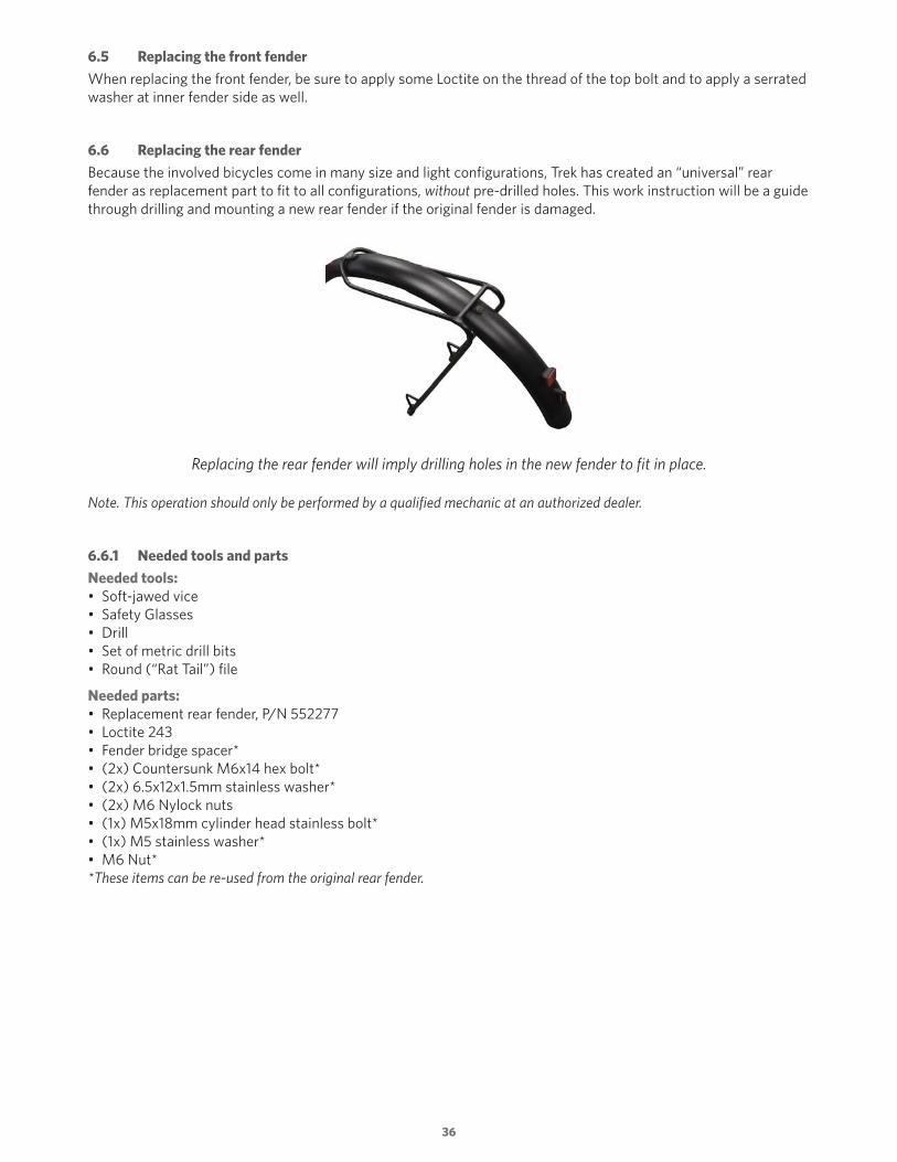
6.6 Replacing the rear fender
Because the involved bicycles come in many size and light configurations, Trek has created an “universal” rear fender as replacement part to fit to all configurations, without pre-drilled holes. This work instruction will be a guide through drilling and mounting a new rear fender if the original fender is damaged.
Replacing the rear fender will imply drilling holes in the new fender to fit in place.
Note. This operation should only be performed by a qualified mechanic at an authorized dealer.
6.6.1 Needed tools and parts
Needed tools:• Soft-jawed vice• Safety Glasses• Drill• Set of metric drill bits• Round (“Rat Tail”) file
Needed parts:• Replacement rear fender, P/N 552277• Loctite 243• Fender bridge spacer*• (2x) Countersunk M6x14 hex bolt*• (2x) 6.5x12x1.5mm stainless washer*• (2x) M6 Nylock nuts• (1x) M5x18mm cylinder head stainless bolt*• (1x) M5 stainless washer*• M6 Nut**These items can be re-used from the original rear fender.
37
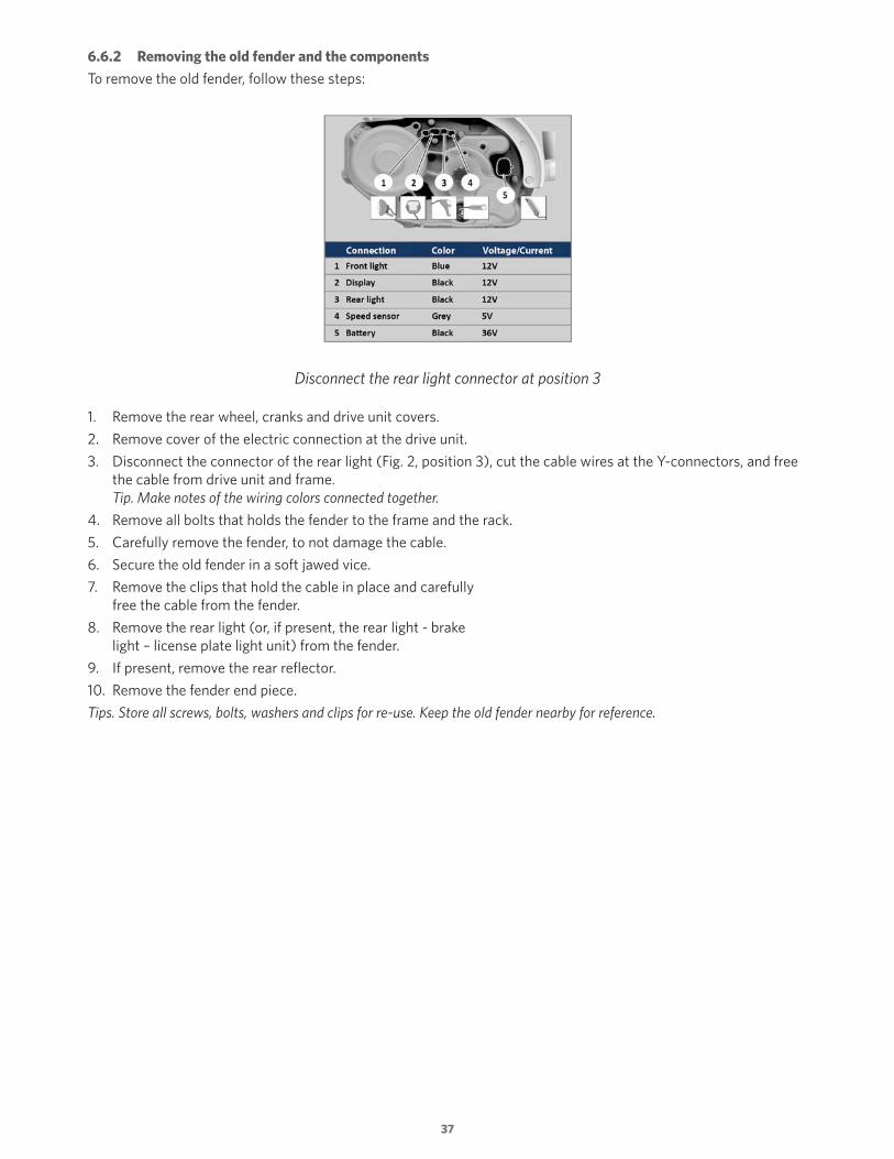
6.6.2 Removing the old fender and the components
To remove the old fender, follow these steps:
Disconnect the rear light connector at position 3
1. Remove the rear wheel, cranks and drive unit covers.
2. Remove cover of the electric connection at the drive unit.
3. Disconnect the connector of the rear light (Fig. 2, position 3), cut the cable wires at the Y-connectors, and free the cable from drive unit and frame. Tip. Make notes of the wiring colors connected together.
4. Remove all bolts that holds the fender to the frame and the rack.
5. Carefully remove the fender, to not damage the cable.
6. Secure the old fender in a soft jawed vice.
7. Remove the clips that hold the cable in place and carefully free the cable from the fender.
8. Remove the rear light (or, if present, the rear light - brake light – license plate light unit) from the fender.
9. If present, remove the rear reflector.
10. Remove the fender end piece.
Tips. Store all screws, bolts, washers and clips for re-use. Keep the old fender nearby for reference.
38
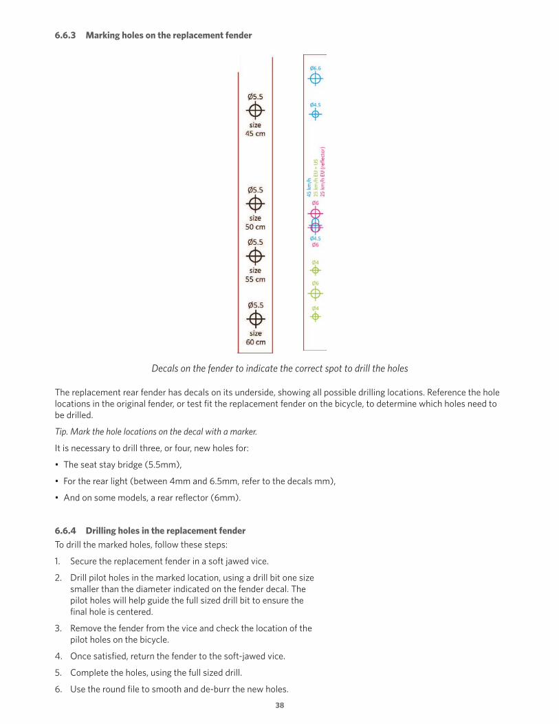
6.6.3 Marking holes on the replacement fender
Decals on the fender to indicate the correct spot to drill the holes
The replacement rear fender has decals on its underside, showing all possible drilling locations. Reference the hole locations in the original fender, or test fit the replacement fender on the bicycle, to determine which holes need to be drilled.
Tip. Mark the hole locations on the decal with a marker.
It is necessary to drill three, or four, new holes for:
• The seat stay bridge (5.5mm),
• For the rear light (between 4mm and 6.5mm, refer to the decals mm),
• And on some models, a rear reflector (6mm).
6.6.4 Drilling holes in the replacement fender
To drill the marked holes, follow these steps:
1. Secure the replacement fender in a soft jawed vice.
2. Drill pilot holes in the marked location, using a drill bit one size smaller than the diameter indicated on the fender decal. The pilot holes will help guide the full sized drill bit to ensure the final hole is centered.
3. Remove the fender from the vice and check the location of the pilot holes on the bicycle.
4. Once satisfied, return the fender to the soft-jawed vice.
5. Complete the holes, using the full sized drill.
6. Use the round file to smooth and de-burr the new holes.
39
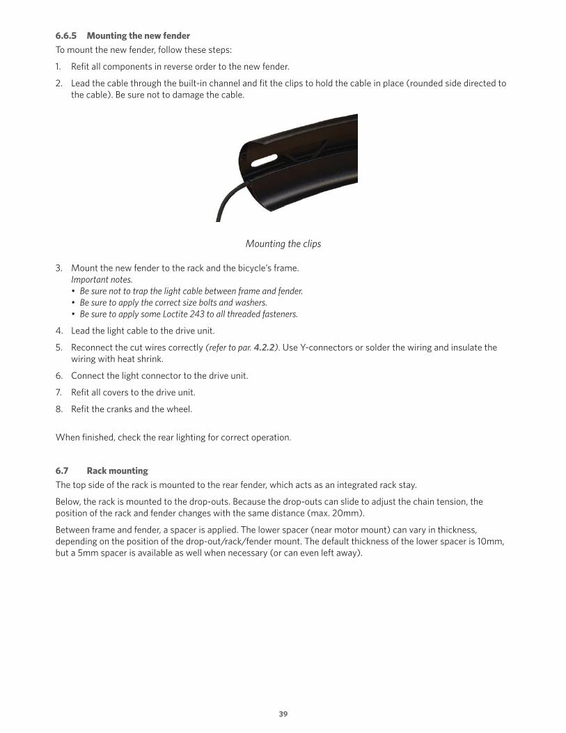
6.6.5 Mounting the new fender
To mount the new fender, follow these steps:
1. Refit all components in reverse order to the new fender.
2. Lead the cable through the built-in channel and fit the clips to hold the cable in place (rounded side directed to the cable). Be sure not to damage the cable.
Mounting the clips
3. Mount the new fender to the rack and the bicycle’s frame. Important notes. • Be sure not to trap the light cable between frame and fender. • Be sure to apply the correct size bolts and washers. • Be sure to apply some Loctite 243 to all threaded fasteners.
4. Lead the light cable to the drive unit.
5. Reconnect the cut wires correctly (refer to par. 4.2.2). Use Y-connectors or solder the wiring and insulate the wiring with heat shrink.
6. Connect the light connector to the drive unit.
7. Refit all covers to the drive unit.
8. Refit the cranks and the wheel.
When finished, check the rear lighting for correct operation.
6.7 Rack mounting
The top side of the rack is mounted to the rear fender, which acts as an integrated rack stay.
Below, the rack is mounted to the drop-outs. Because the drop-outs can slide to adjust the chain tension, the position of the rack and fender changes with the same distance (max. 20mm).
Between frame and fender, a spacer is applied. The lower spacer (near motor mount) can vary in thickness, depending on the position of the drop-out/rack/fender mount. The default thickness of the lower spacer is 10mm, but a 5mm spacer is available as well when necessary (or can even left away).

40
6.8 Mounting the drive unit
6.8.1 Replacing the drive unit
The Bosch drive unit is mounted to the frame with help of a specially designed support bracket.
Note:When the drive unit must be replaced, the replacement drive unit must be of Bosch model year 2017 or newer, as older units cannot deliver 12 Volt on the light connections.
When replacing the drive unit, follow these steps:
1. Remove the motor armor.
2. Remove the chain wheel and chain from the drive unit.
3. Remove all covers.
4. Remove the cranks.
5. Disconnect all electrical connections.
6. Loosen the motor bolts.
7. Carefully remove the drive unit from the frame.
Tip. Take a picture, or notes, of the position of all cables to/near the drive unit.
8. Remove the motor plate from the drive unit.
9. Mount the motor plate to the new drive unit and mount the drive unit to the frame.
10. Mount all other parts in reverse order.
Important. 1. Ensure to not trap cables and/or wiring between frame and drive unit. 2. Ensure to fit the additional bushing (!) on the top motor bolt.
11. Change the voltage on the light ports from 6 Volt to 12 Volt with help of the Bosch diagnose software.
Important note. The default voltage on the replacement drive unit is 6 Volt. With help of the Bosch diagnose software, the voltage to power the lights can be switched to 12 Volt (the maximum current, in total, is 1500 mA)
12. Test the system for normal operation.

41
6.8.2 Drive unit mounting - technical drawing
Mounting parts of the drive unit
1. Additional bushing, L=5mm (!)2. Bolts drive unit.
(Pos. 2.1 and 2.2: M8x60, 10,9 cylinder head, pos. 2.3: M8x60, 10.9, hex. head, from Bosch kit)
3. Bolt chain guide (M5x18, A2, 1x)4. Chain guide5. Drive unit
6. Motor plate7. Bolts motor plate (M5x16, 10.9, A2, 2x)8. Cover of electric connections drive unit9. Screw of cover (M4x10, A2, 1x)10. Washer and nut of 3rd drive unit bolt (M8, A2, 1x, Bosch kit)11. Bolts and washers motor armor (M5x14, A2, 4x)12. Motor armor

42
7. Spare parts
7.1 Spare parts - bicycle
Part P/N For Description Region
Battery rail W545411 Trek/Diamant Battery rail Global
Chain guide W545333 Trek/Diamant Chain guide Global
Charge cover W543503 Trek/Diamant Charge cover Global
Derailleur guard W544828 Trek/Diamant Derailleur guard Global
Derailleur hanger W543589 Trek/Diamant Derailleur hanger Global
Drop-outs derailleur 550758 Trek/Diamant Drop-out kit, derailleur Global
Drop-outs IGH 550759 Trek/Diamant Drop-out kit, IGH EU only
Fenders 552276 Trek/Diamant Front fender Global
552277 Trek/DiamantRear fender (to be fitted per frame size; refer to par.6.6)
Global
Fork 550689 Trek Painted fork, red Global
550688 Trek Painted fork, black EU Only
550638 Diamant Painted fork, charcoal GAS* only
550639 Diamant Painted fork, brown GAS* only
Lighting W544131 Trek/Diamant Supernova E3 front light EU only
W546989 Trek/Diamant Supernova M99 Pro front light EU only
W549723 Trek/Diamant Supernova M99 Pure+ front light US* only
W544077 Trek/Diamant Supernova E3 rear light Global
W543228 Trek/Diamant Supernova M99 rear light (45kmh only) EU only
W546512 Trek/Diamant Light switch EU only
551749 Trek/Diamant Brake light cable EU only
551750 Trek/Diamant Rear light cable EU only
Motor cover W543504 Trek/Diamant Motor cover Global
Motor armor 550755 Trek Painted motor armor, black Global
550756 Diamant Painted motor armor, brown GAS* only
550757 Diamant Painted motor armor, charcoal GAS* only
Motor plate W544078 Trek/Diamant Motor mounting hardware Global
Rack 552278 Trek/Diamant Rack Global
Rail spacer W545232 Trek/Diamant Rail spacer Global
Rim W544119 Trek/Diamant Custom Alex rim Global
Stem face plate 550690 Trek/Diamant Stem face plate Global
* GAS = Germany, Austria, Switzerland (Diamant) US = United States
Spare parts can be ordered via Dexter / Tech Site.

43
7.2 Spare parts - Bosch eBike System
Spare parts of the Bosch eBike System can be ordered via the Bosch/Magura webshop.
7.3 Disposal
No longer used parts and packaging materials should be disposed of in an environmentally, correct manner according to local laws.
7.3.1 Disposal of electrical components
All electrical components, the drive unit, on-board computer including operating unit, battery pack, speed sensor, and accessories should be disposed of in an environmentally correct manner. Do not dispose of these electrical parts into household waste!
7.3.2 Disposal of batteries
Because a battery pack contains certain harmful substances, it must be treated as chemical waste and may not be disposed as normal waste.
Tape or mask off the contact surfaces of the battery’s terminals with adhesive tape before disposing of batteries.
Only for EC countries:According to the European Guideline 2012/19/EU, electrical devices/tools that are no longer usable, and according to the European Guideline 2006/66/EC, defective or used battery packs/batteries, must be collected separately and disposed of in an environmentally correct manner.

44
8. RIDE+ Owner’s manuals
8.1 RIDE+ Owner’s manuals - content and languages
The content of the RIDE+ Owner’s printed manual delivered with the bicycles is depending on the region of sale and the exact configuration of the applied Bosch kit. It handles about the operation of, and detailed information about the Bosch eBike Assist system and the safe use of electrically assisted bicycles.
Note: For ‘general’ bicycle information, please refer to the Trek or Diamant Owner’s manual, delivered with the bicycle.
8.1.1 RIDE+ Owner’s manual for bicycles sold in Europe
The bicycles for Europe come with a printed edition of the RIDE+ Owner’s manual in English, German, Dutch and French; also digitally available online (PDF). Online more languages (Spanish, Italian, Portuguese, Danish, Norwegian, Swedish and Finnish) are digitally available (PDF).
8.1.2 RIDE+ Owner’s manual for bicycles sold in the US
The bicycles for the US come with a US - specific printed edition of the RIDE+ Owner’s manual in English, French and Spanish; also digitally available online (PDF).
8.2 RIDE+ Owner’s manuals - overview MY2017
Refer to Tech Site (RIDE+ section) or to http://www.trekbikes.com/us/en_US/manuals/ for all available digital editions of the Owner’s manuals (PDF).
Note.
RIDE+ Owner’s manuals with languages EN-DE-NL-FR (EU) and EN-FR-ES (US) are delivered as a booklet with the bicycles and also are digitally available online (PDF).
RIDE+ Owner’s manuals with languages ES-IT-PT-DA-NO-SV-FI are only digitally available online (PDF).


P/N 553501 Rev.AFebruary 2017 © Copyright 2017 Trek Bicycle Corporation All rights reserved.