[email protected] paper 33 united states patent and
TRANSCRIPT
[email protected] Paper 33 571-272-7822 Entered: May 22, 2019
UNITED STATES PATENT AND TRADEMARK OFFICE
____________
BEFORE THE PATENT TRIAL AND APPEAL BOARD ____________
SYRINIX, INC.,
Petitioner,
v.
BLACOH FLUID CONTROL, INC., Patent Owner.
_______________
Case IPR2018-00414 Patent 7,219,553 B1 _______________
Before SCOTT C. MOORE, CHRISTA P. ZADO, and FREDERICK C. LANEY, Administrative Patent Judges. LANEY, Administrative Patent Judge.
FINAL WRITTEN DECISION
Determining Claims 1–6, 10, 12, and 14 Unpatentable in Inter Partes Review
35 U.S.C. § 318(a) and 37 C.F.R. § 42.73
Granting Patent Owner’s Motion to Amend 35 U.S.C. § 316(d) and 37 C.F.R. § 42.121
Granting Patent Owner’s Motion to Seal
37 C.F.R. §§ 42.14 and 42.54

IPR2018-00414 Patent 7,219,553 B1
1
I. INTRODUCTION
A. Background
Syrinix, Inc. (“Petitioner”) filed a Petition (Paper 1; “Pet.”) to institute
an inter partes review of claims 1–21 of U.S. Patent No. 7,219,553 B1 (Ex.
1001; “the ’553 patent”) supported by a Declaration of Paul Lander, Ph.D.,
(Ex. 1002). Blacoh Fluid Control, Inc. (“Patent Owner”) filed a Preliminary
Response (Paper 7; “Prelim. Resp.”). Upon consideration of the Petition, the
Preliminary Response, and the evidence cited by the parties, we determined
that Petitioner established a reasonable likelihood that it would prevail with
respect to at least one of the claims challenged in the Petition and instituted
review to determine the patentability of the challenged claims on all grounds
raised in the Petition. Paper 8, 1 (“Dec. Inst.”).
After institution, Patent Owner filed a Response to the Petition
(Paper 22, “PO Resp.”) supported by Declarations of Dan Cenatempo (Ex.
2015), Loren Worthington (Ex. 2016), and Frank Knowles Smith, III, (Ex.
2017). In addition, Patent Owner filed a Contingent Motion to Amend,
seeking to replace claims 1, 13, and 14 with substitute claims 22–24 (Paper
20, “PO MTA”). Petitioner filed a Reply to Patent Owner’s Response
(Paper 25, “Pet. Reply”) and an Opposition to the Motion to Amend (Paper
24, “Pet. Opp. MTA”), both supported by a second Declaration of Paul
Lander (Ex. 1016). Patent Owner filed a Reply in support of its Motion to
Amend (Paper 28, “PO Reply MTA”) and a Sur-Reply in support of its
Response to the Petition (Paper 27, PO Sur-Reply Resp.”). Patent Owner
also deposed Dr. Lander, and submitted the deposition transcript as
evidence. Ex. 2005. Finally, Petitioner filed a Sur-Reply in support of its

IPR2018-00414 Patent 7,219,553 B1
2
Petition responding to Patent Owner’s Sur-Reply (Paper 29, “Pet. Sur-
Reply”).
An oral hearing was held on January 15, 2019, and the hearing
transcript is included in the record. See Paper 32 (“Tr.”). We have
jurisdiction under 35 U.S.C. § 6(b). This is a Final Written Decision under
35 U.S.C. § 318(a) and 37 C.F.R. § 42.73.
For the reasons set forth below, Petitioner has shown by a
preponderance of evidence that claims 1–6, 10, 12, and 14 of the ’553 patent
are unpatentable. Petitioner has not shown by a preponderance of the
evidence that claims 7–9, 11, 13, and 15–21 are unpatentable. Because
Patent Owner’s Motion to Amend is contingent upon a finding of
unpatentability with respect to the original claims, we reach proposed
substitute claims 22 and 24, which substitute claims 1 and 14. However, we
do not reach proposed substitute claim 23, which would substitute claim 13.
B. Related Matters
Petitioner indicates that the ’553 patent is the subject of a lawsuit
between Petitioner and Patent Owner in the U.S. District Court for the
Northern District of California (Ex. 1007, Blacoh Fluid Controls, Inc. v.
Syrinix, Inc., No. 5:17-cv-04007-NC). Pet. 8; Paper 4, 1. Additionally, the
U.S. Patent No. 7,357,034 B1 (“the ’034 patent) indicates that it is a
divisional of the application that issued as the ’553 patent, which the parties
indicate is also a subject of the above lawsuit and IPR2018-00415. Id.
C. References and Materials Relied Upon
Petitioner relies on the following references and materials in support
of the asserted grounds of unpatentability:

IPR2018-00414 Patent 7,219,553 B1
3
References and Materials Exhibit No. U.S. Patent No. 4,908,775 (iss. Mar. 13, 1990) (“Palusamy”)
1009
U.S. Patent No. 5,987,990 (iss. Nov. 23, 1999) (“Worthington”)
1010
WO 01/51386 A1 (pub. July 19, 2001) (“ZIP”)
1011
U.S. Patent No. 4,161,782 (iss. July 17, 1979) (“McCracken”)
1012
U.S. Patent No. 5,708,195 (iss. Jan. 13, 1998) (“Kurisu”)
1013
Declarations of Paul Lander 1002, 1016
D. Instituted Grounds of Unpatentability
We instituted review on the following asserted grounds of
unpatentability:
Grounds Challenged Claim
Statutory Basis1
Reference(s)
1 1–6, 11, 12, and 14–18
35 U.S.C. § 102 Palusamy
2 7–9, 13, 20, and 21
35 U.S.C. § 103 Palusamy and Worthington
3 10 and 19 35 U.S.C. § 103 Palusamy and ZIP
4 14 35 U.S.C. § 103 Palusamy and McCracken
5 3, 5, and 11 35 U.S.C. § 103 Palusamy and Kurisu
6 1–6, 11, 12, and 14–18
35 U.S.C. § 103 Palusamy and McCracken
1 Because the patent application resulting in the ’553 patent was filed before the effective date of the Leahy Smith America Invents Act (“AIA”), we refer to the pre-AIA versions of 35 U.S.C. §§ 102 and 103.
IPR2018-00414 Patent 7,219,553 B1
4
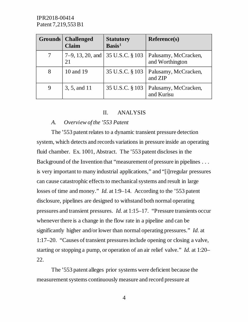
Grounds Challenged Claim
Statutory Basis1
Reference(s)
7 7–9, 13, 20, and 21
35 U.S.C. § 103 Palusamy, McCracken, and Worthington
8 10 and 19 35 U.S.C. § 103 Palusamy, McCracken, and ZIP
9 3, 5, and 11 35 U.S.C. § 103 Palusamy, McCracken, and Kurisu
II. ANALYSIS
A. Overview of the ’553 Patent
The ’553 patent relates to a dynamic transient pressure detection
system, which detects and records variations in pressure inside an operating
fluid chamber. Ex. 1001, Abstract. The ’553 patent discloses in the
Background of the Invention that “measurement of pressure in pipelines . . .
is very important to many industrial applications,” and “[i]rregular pressures
can cause catastrophic effects to mechanical systems and result in large
losses of time and money.” Id. at 1:9–14. According to the ’553 patent
disclosure, pipelines are designed to withstand both normal operating
pressures and transient pressures. Id. at 1:15–17. “Pressure transients occur
whenever there is a change in the flow rate in a pipeline and can be
significantly higher and/or lower than normal operating pressures.” Id. at
1:17–20. “Causes of transient pressures include opening or closing a valve,
starting or stopping a pump, or operation of an air relief valve.” Id. at 1:20–
22.
The ’553 patent alleges prior systems were deficient because the
measurement systems continuously measure and record pressure at

IPR2018-00414 Patent 7,219,553 B1
5
predetermined, fixed intervals. Id. at 2:25–43. These systems are generally
set to sample the pressure sensor(s) at intervals of once per day, once per
hour, or once per minute. Id. at 2:36–38. The problem with a fixed interval
system, the ’553 patent explains, is that a transient pressure may occur
between the times the pressure samples are taken and, therefore, would have
no record of its occurrence. Id. at 2:25–43. For example, “some of the most
severe transients will have a duration of less than one second, and will not be
accurately measured by set-interval data recording systems.” Id. at 2:38–41.
An object of the invention is to improve the detection and accuracy of
recording transient pressures in pipelines and other operating fluid
chambers. Id. at 2:44–46.
The ’553 patent discloses a system and method that detects transient
pressures and locates the source of the transient pressures to provide
information that may be used to avoid such transients during future
operations. Ex. 1001, 2:50–56. To accomplish this objective, the system
includes a dynamic pressure sensor placed within an operating fluid
chamber, which continuously measures the pressure and time of the fluid
pressure without operator interface. Id. at 2:57–63. Signals indicating the
pressure within the fluid chamber are transferred through a transmission
system to a receiver, which a signal processor converts, if needed, and
records as data. Id. at 2:61–3:6. In addition, using a clock or timer, each
signal is associated with timing data to establish a chronological order of
each measurement signal detected, and may further included associated
positioning information for locating the event. Id. “A data management
program then analyzes the collected data and displays results.” Id. at 3:6–8.
IPR2018-00414 Patent 7,219,553 B1
6
In operation, the signal processor receives and records data samples at
a predetermined sampling rate. Ex. 1001, 3:9–11. This sampling rate “can
vary widely depending on the use and are set by an operator using the
principles of physics and digital data processing; however, multiple samples
per second are normally taken by the system.” Id. at 4:3–6. At the set
intervals, data samples are provided to a receiver and a signal processor
analyzes the information to determine whether there is a transient pressure in
the operating fluid chamber. Id. at 3:19–27. To accurately identify transient
pressures of concern, the desired transient pressure parameters must be
defined for the system, which may, for example, be an absolute threshold of
pressure change or a statistical departure from the steady state pressure. Id.
at 3:34–40.
Depending on whether pressure data exceeds the set transient
pressure threshold, the signal processor controls the data rate sampling
and/or data recording rates. Id. at 3:28–30. “The operator can adjust the
data sample recording frequencies as needed for a particular application.”
Ex. 1001, 3:42–44. Generally, the steady state pressure data is stored
periodically at a different, slower sampling rate than transient pressure data.
Id. at 3:40–42. “If the user desires, data samples in steady pressure
conditions may be recorded at rates including, but not limited to, once per
day.” Id. at 4:10–12. On the other hand, data pressure signals indicating a
pressure greater than the set transient pressure threshold are stored at a
higher sampling rate, which may be, but are not limited to, thousands of
samples per second. Id. at 4:3–8. Thus, when the sensors indicate a
pressure measurement that, when compared to the steady state pressure, is
IPR2018-00414 Patent 7,219,553 B1
7
outside the set pressure threshold, the system records more pressure data for
the transient pressure event to give operators more information.
The system continues to sample and/or record the pressure sensor data
at the higher frequency until the pressure returns to a steady state value. Id.
at 3:28–30. Contemporaneously, the times of detection and/or position of
the sensor are recorded and sent with the pressure data. Id. at 3:59–63. And
all of the data is received and analyzed by a data management program, and
the results are displayed to the user. Id. at 3:6–8.
B. Representative Claim of the ’553 Patent
The ’553 patent has a single independent claim, which is challenged
claim 1. Claim 1 is representative of the claimed subject matter and is
reproduced below.
1. A dynamic transient pressures detection system comprising:
a dynamic transient pressure sensor installed in an operating fluid chamber,
a transmission system for transferring a signal indicating pressure within the operating fluid chamber to a receiver,
a clock or timer for recording chronological time detection,
a signal processor for receiving signals and recording data, and
a data management program for analyzing and displaying collected data, wherein the signal processor records data samples showing dynamic transient pressures above a threshold level to internal memory until pressure returns to a steady state or until the user specifies.
C. Level of Ordinary Skill in the Art
The level of ordinary skill in the art to which the ’553 patent pertains
is relevant to claim construction, anticipation, and obviousness. Petitioner
IPR2018-00414 Patent 7,219,553 B1
8
asserts that the class of people having ordinary skill in the art would either
have an undergraduate engineering degree and “at least two years of prior
experience with pipeline measurement and fluid flow characterization
techniques” or “a post-graduate degree in signal processing concepts.” Pet.
15 (citing Ex. 1002 ¶¶ 26–28, 30). Such a person, according to Petitioner,
“would be familiar with prior art teachings of detection systems and methods
for various causes of transient conditions, such as a water hammer, a flow
disturbance along a fluid flow path, or a leak or diversion along a fluid flow
path.” Id. (citing Ex. 1002 ¶ 29).
Patent Owner does not set forth a specific formulation regarding the
level of ordinary skill in the art, or object to Petitioner’s contentions
regarding who would qualify as one of ordinary skill in the art.
Furthermore, Patent Owner does not suggest Petitioner’s proposal for the
level of ordinary skill would lead to an incorrect understanding of how a
skilled artisan would understand either the ’553 patent or the prior art.
In our Institution Decision, we declined to adopt a specific
formulation regarding the level of ordinary skill in the art, and instead found
the cited references to be representative of the level of ordinary skill in the
art. Inst. Dec. 9–10 (citing Okajima v. Bourdeau, 261 F.3d 1350, 1355 (Fed.
Cir. 2001) (the level of ordinary skill in the art may be evidenced by the
cited references themselves)). The parties have not expressed any
disagreement with this finding, nor have they suggested a more definitive
characterization of the level of ordinary skill in the art is necessary to resolve
a disputed issue. Accordingly, for purposes of this Decision we again treat
the cited references as being representative of the level of skill in the art.
However, the factual findings and legal conclusions set forth herein would
IPR2018-00414 Patent 7,219,553 B1
9
have been the same had we instead applied Petitioner’s proposed
formulation regarding the level of ordinary skill in the art.
D. Claim Construction
In inter partes reviews filed before November 13, 2018, the Board
interprets claims of an unexpired patent using the broadest reasonable
interpretation in light of the specification of the patent in which they appear.
See 37 C.F.R. § 42.100(b); Cuozzo Speed Techs., LLC v. Lee, 136 S. Ct.
2131, 2144–46 (2016); Changes to the Claim Construction Standard for
Interpreting Claims in Trial Proceedings Before the Patent Trial and Appeal
Board, 83 Fed. Reg. 51,340 (Oct. 11, 2018). Consistent with the rule of
broadest reasonable interpretation, claim terms are generally given their
plain and ordinary meaning, as would be understood by one of ordinary skill
in the art in the context of the entire disclosure. See In re Translogic Tech.,
Inc., 504 F.3d 1249, 1257 (Fed. Cir. 2007). Only those terms in controversy
need to be construed and only to the extent necessary to resolve the
controversy. See Nidec Motor Corp. v. Zhongshan Broad Ocean Motor Co.
Matal, 868 F.3d 1013, 1017 (Fed. Cir. 2017) (citing Vivid Techs., Inc. v. Am.
Sci. & Eng’g, Inc., 200 F.3d 795, 803 (Fed. Cir. 1999) (explaining that only
those claim terms that are in controversy need to be construed, and only to
the extent necessary to resolve the controversy).
Petitioner proposes constructions for the following terms and phrases:
“[r]ecord(s),” “store(s),” “contains,” “[p]redetermined periodic interval,”
“[i]dentifies,” and “[i]nstrument.” Pet. 20–21. Patent Owner does not raise
any specific, substantive objection to Petitioner’s proposed constructions.
None of the issues raised in this case depends on the precise meaning of the
IPR2018-00414 Patent 7,219,553 B1
10
above claim limitations, however. Thus, we do not provide express
constructions of these terms. See Nidec Motor Corp., 868 F.3d at 1017.
Patent Owner proposes constructions for the following terms and
phrases: “dynamic transient pressures” (claim 1); “dynamic transient
pressure sensor” (claim 1); “threshold level” (claim 1); and “predetermined
threshold of pressure” (claim 11). PO Resp. 18–39. Patent Owner contends
claims are to be accorded their broadest reasonable interpretation in light of
the specification, but argues that the patentee can disavow the full scope of
the claim in the specification or during prosecution. Id. at 17. The parties
agree that “predetermined threshold of pressure” has its plain and ordinary
meaning, and do not raise any controversy concerning the interpretation of
this claim term. Therefore, we do not provide an express construction for
this term. See PO Resp. 38; Pet. Reply 11. The parties, however, have
substantive disagreements regarding “dynamic transient pressure” (which
also affects the interpretation of “dynamic transient pressure sensor”) and
“threshold level.” We address these disputed terms below. .
1. “dynamic transient pressures” and “dynamic transient pressure sensor”
Patent Owner contends that the intrinsic evidence from the ’553 patent
supports interpreting “dynamic transient pressure” as “a pressure fluctuation,
including fluctuations lasting less than one second,” moreover, interpreting
“dynamic transient pressure sensor” as “ a device configured to measure and
record pressure fluctuations, including fluctuations lasting less than one
second.” PO Resp. 18. We note Patent Owner’s proposed construction of
“dynamic transient pressure sensor” is equivalent to “a device configured to
measure and record dynamic transient pressures.” There does not appear to
IPR2018-00414 Patent 7,219,553 B1
11
be a dispute, however, that the “dynamic transient pressure sensor” is a
device configured to measure dynamic transient pressures. Therefore, we
focus our discussion on the dispute raised with regard to the phrase
“dynamic transient pressure.”
Patent Owner contends, “‘dynamic transient pressure’ detection
within the meaning of the ’553 Patent requires, at a minimum, detecting
pressure fluctuations including fluctuations lasting less than one second.”
Id. Patent Owner’s arguments disputing Petitioner’s unpatentability
contentions assert that the prior art “does not disclose the ‘transient’
detection of the ’553 Patent claims” because it does not show a system
configured to detect pressure fluctuations lasting less than one second. Id. at
41. In the prior art system, according to Patent Owner, pressure fluctuations
lasting less than one second “would go completely undetected.” Id.
Petitioner contends Patent Owner’s construction of “dynamic transient
pressure” improperly deviates from its plain meaning by incorporating “a
specific identifier of pressure fluctuations ‘lasting less than one second.’”
Pet. Reply 1. Petitioner proposes that the plain meaning of “dynamic
transient pressure” is “constantly changing pressure values of a short
duration.” Id. Petitioner does not separately address the phrase “dynamic
transient pressure sensor.” See id. at 1–6.
From Petitioner’s and Patent Owner’s proposed construction, the
parties agree that a skilled artisan would understand, in the context of the
’553 patent, that the phrase “dynamic transient pressure” refers to a
temporary variation in pressure from the normal operating pressure. We
agree also. This is consistent with the specification of the ’553 patent, which
states that “[p]ressure transients occur whenever there is a change in the
IPR2018-00414 Patent 7,219,553 B1
12
flow rate in a pipeline and can be significantly higher and/or lower than
normal operating pressures.” Ex. 1001, 1:17–20. The parties disagree,
however, on whether the limitation “dynamic transient pressure” requires the
ability to detect pressure fluctuations lasting less than one second, as well as
other fluctuations lasting more than one second. See, e.g., PO Resp. 41
(arguing that Palusamy “does not disclose ‘transient’ detection” because
“‘[d]ynamic transient pressures,’ which include pressure fluctuations lasting
less than one second (under a proper construction), would go completely
undetected”); see also, e.g., Reply 2 (arguing Patent Owner arbitrarily
selects “less than one second,” even though the specification of the ’553
patent “nowhere states that pressure fluctuations lasting less than ‘one
second’ need to be detected”). The claim construction dispute that we must
address, therefore, boils down to whether “dynamic transient pressure”
requires the system of claim 1 to have a configuration that can detect
pressure fluctuations lasting less than one second.
We begin addressing this issue where we left off in the Institution
Decision. See Dec. Inst. 10–16. Addressing similar contentions made in the
Preliminary Response, the Institution Decision considered whether the
specification of the ’553 patent, and its file history, provide a context that
would lead a skilled artisan to understand “transient pressure” to require a
configuration that can at least detect pressure fluctuations lasting less than
one second. Id. After considering the intrinsic record and Patent Owner’s
arguments, we “reject[ed] Patent Owner’s assertion that the claimed
invention, as a whole, is limited to a configuration that detects/monitors
pressure fluctuations lasting less than one second.” Id. at 16. Notably, our
Institution Decision did not suggest that detecting pressure fluctuations

IPR2018-00414 Patent 7,219,553 B1
13
lasting less than one second would fall outside the scope of the claims.
Rather, we determined that the claim limitation “dynamic transient pressure”
does not limit the scope of the claimed invention to a configuration that can
at least detect pressure fluctuations lasting less than one second. At the
hearing for this matter, Petitioner represented that it “actually prefer[s]” the
construction we advanced in the Institution Decision and that it “would like
that to be adopted.” Tr. 15:8–11.
Many of the arguments in Patent Owner’s Response are substantially
similar to those made in its Preliminary Response (compare Prelim. Resp. 9–
16 with PO Resp. 18–31) and we remain convinced that “dynamic transient
pressure” does not limit the scope of claim 1 to having a configuration
capable of detecting pressure fluctuations lasting less than one second for the
same reasons we provide in the Institution Decision. See Dec. Inst. 10–16.
Our conclusion in this regard is consistent with the Federal Circuit’s holding
that when a claim uses generally descriptive words to define a limitation, it
is ordinarily improper to construe it to have a numerical range that may
appear in the written description. See Conoco, Inc. v. Energy & Envtl. Int’l,
L.C., 460 F.3d 1349, 1357–58 (Fed. Cir. 2006) (“[W]hen a claim term is
expressed in general descriptive words, we will not ordinarily limit the term
to a numerical range that may appear in the written description or in other
claims.”) (quoting Renishaw PLC v. Marposs Societa’ per Azioni, 158 F.3d
1243, 1249 (Fed. Cir. 1998)).
Patent Owner argues that our determination in the Institution Decision
that “transient is not limited to pressure fluctuations lasting less than one
second, but rather includes temporary pressure variations that ‘occur
whenever there is a change in the flow rate in a pipeline,’” appears to

IPR2018-00414 Patent 7,219,553 B1
14
support its position. PO Resp. 34–36 (citing Dec. Inst. 16). Patent Owner
“agrees that ‘transient’ is not limited to pressure fluctuations lasting less than
one second,” but asserts it “must include ‘pressure fluctuations lasting less
than one second.’” Id. at 34. Patent Owner also “agrees that ‘transient’
includes ‘temporary pressure variations that occur whenever there is a
change in the flow rate in a pipeline,’” but only “to the extent ‘whenever’
means detecting transients every time they occur.” Id. Patent Owner argues
that our determination that a skilled artisan would understand “transient” to
include temporary pressure variations that occur whenever there is a change
in the flow rate in a pipeline “implies that ‘dynamic transient pressure
sensor’ means detecting temporary pressure variations whenever (i.e., every
time) they occur.” Id. at 34–35.
Therefore, the issue before us regarding the claim phrase “dynamic
transient pressure” is whether the intrinsic record of the ‘553 patent would
be understood by a person of ordinary skill in the art to require a
configuration that detects pressure fluctuations lasting at least less than one
second. After studying the intrinsic record, we previously found, and now
find once again, that it does not include a lexicographic definition,
disclaimer, or other language that would have been understood by a skilled
artisan to impart such a meaning to “dynamic transient pressure.” See Dec.
Inst. 10–16.
This case is analogous to In re Hiniker wherein the specification
taught operational advantages that were inherent in the claimed invention,
but the claims failed to distinguish the invention based on the advantages
described. 150 F.3d 1362, 1368 (Fed. Cir. 1998). In that case, the
operational advantages related to providing “downward force via the attack

IPR2018-00414 Patent 7,219,553 B1
15
angle of the point member.” The patent owner in that case argued that the
claim phrase “said point member provides a downward force on said sweep
when being pulled through the soil” should be interpreted to require the
shovel attack angle to be such it caused reaction forces that are mainly
downward, rather than backward. Id. The Federal Circuit explained that,
because the claims did not quantify the downward force or otherwise recite
structure that would so limit their coverage, importing these operational
characteristic would be improper. Id. “Although operational characteristics
of an apparatus may be apparent from the specification, we will not read
such characteristics into the claims when they cannot be fairly connected to
the structure recited in the claims.” Id.
Here, Patent Owner attempts similarly to use the transient phrases to
import an operational characteristic that those phrases themselves do not
require because, while “dynamic transient pressures” and “transient
pressures” include temporary pressure fluctuations lasting less than one
second, these phrases also encompass temporary pressure fluctuations
lasting more than one second. See e.g., Ex. 2004, 1:17–20 (“a transient
event is rapid, unusual, short duration deviation from normal operation
(typically a few seconds) which is large in magnitude”) (emphasis added);
see also, PO Resp. 25–26 (stating column 1, lines 17–20, from Exhibit 2004,
shows how a skilled artisan would have understood the transient phrases).
As a result, our determination is that it would be improper to interpret
“dynamic transient pressure” to require detection of temporary pressure
fluctuations lasting less than one second.
Patent Owner argues that “[i]f the claims are construed to encompass
a system that detects slow pressure waves but not severe transients using a

IPR2018-00414 Patent 7,219,553 B1
16
slow sample rate, that would defeat the fundamental premise of the patent
and contradict the prosecution history.” PO Resp. 35. It is unclear,
however, what Patent Owner means by the phrase “slow pressure waves.”
Nevertheless, this argument is unpersuasive because we have not construed
the claims “to encompass a system that detects slow pressure waves but not
severe transients using a slow sample rate.” To clarify our construction
further, however, we agree with Patent Owner that the meaning of “dynamic
transient pressure,” in the context of the ’553 patent, does not encompass
those pressure fluctuations caused solely by pipe leakage for the following
reasons.
An applicant may narrow the meaning of a claim term by disclaiming
or disavowing claim scope; however, such a “disclaimer or disavowal of
claim scope must be clear and unmistakable, requiring ‘words or expressions
of manifest exclusion or restriction’ in the intrinsic record.” Unwired Planet,
LLC v. Apple Inc., 829 F.3d 1353, 1358 (Fed. Cir. 2016) (quoting Teleflex,
Inc. v. Ficosa N. Am. Corp., 299 F.3d 1313, 1327 (Fed. Cir. 2002)). During
prosecution of the ’553 patent, the applicant made the following clear
representations:
Dynamic transient pressures are described through the specification and in Figure 1 and the original claims as the dangers to vessel or pipeline integrity which must identified. That is not the same as leak detection (Ex. 1005, 48) (emphasis added); and
Claim 1 distinguishes Applicant’s invention by providing a dynamic transient pressure detection system in a fluid chamber, while Kurisu looks only for pipeline leaks. Furthermore, claim 1 distinguishes applicant’s invention by detecting and monitoring any dynamic transient pressure in a fluid chamber, rather than merely detecting ‘pressure waves’
IPR2018-00414 Patent 7,219,553 B1
17
caused by a leak as in Kurisu (Ex. 1005, 48–49) (emphasis added).
We find the above remarks made during prosecution of the ’553 patent by
the applicant to be an unmistakable disavowal of pressure fluctuations
caused by a leak in a pipe from the scope of “dynamic transient pressure.”
Accordingly, we agree with Patent Owner that the applicant narrowed the
scope of “dynamic transient pressure” to exclude transient pressures caused
by pipeline leaks.
To summarize, after considering the evidence intrinsic to the ’553
patent, we determine that the broadest reasonable meaning of “dynamic
transient pressure” is not limited to temporary pressure fluctuations lasting
less than one second. Accordingly, the claim limitation “transient dynamic
pressure” does not restrict the invention of claim 1 to a configuration that
can detect at least the subset of pressure fluctuations lasting less than one
second. To add clarity, and address Patent Owner’s concern that we have
swept into the meaning of “dynamic transient pressure” subject matter
expressly disclaimed, we determine further that the applicant clearly
disavowed a meaning of “dynamic transient pressure” that includes pressure
fluctuations caused solely by leaks in a pipe.
2. “threshold level” Patent Owner contends “threshold level” means “a preset amount of
pressure variation.” PO Resp. 37 (citing Ex. 1001, 3:9–12, 5:66–6:1, 6:34–
37, Fig. 1). Patent Owner contends, “‘[t]hreshold level’ refers specifically to
a preset amount of pressure variation or change in pressure rather than a
specific pressure value.” Id. at 38. Pointing to Figure 1 of the ’553 patent,
Patent Owner argues that it shows that the “threshold level cannot be a static

IPR2018-00414 Patent 7,219,553 B1
18
pressure value because pressure values above and below steady state are
both recorded in internal memory.” Id. Patent Owner concludes that
Figure 1 evidences that the “samples are recorded based on their variation,
not because they exceed a fixed pressure value.” Id.
Petitioner argues that Patent Owner’s proposed construction is
“deceptively simple” and applied in an allegedly “disingenuous way” to
distinguish the prior art. Pet. Reply 7. Specifically, Petitioner argues that
Patent Owner applies its proposed construction in a manner that “advances a
‘rate-based’ construction for ‘threshold level’ that includes a notion of ‘rate,’
for comparison with ‘rate’ of pressure variation or ‘rate’ of pressure
change.” Id. at 9 (citing PO Resp. 46–47 (“Mathematically speaking,
comparing one pressure to another is different than determining a rate of
change.”)). This meaning, Petitioner argues, “is reading a limitation borne
of [Patent Owner’s] imagination into [the] claim.” Id. at 10.
Petitioner contends that “threshold level” means “(1) a predefined
pressure threshold value relative to steady state pressure; (2) an absolute
threshold of pressure change from a steady state pressure; or (3) a statistical
departure from a steady state pressure.” Pet. Reply 7 (citing Ex. 1016, ¶ 24).
Petitioner contends the specification of the ’553 patent supports this
construction because it describes the signal processor as recording “any
variation in pressure above a set threshold” and states,
[t]he definition of transient pressure parameter may include the definition of an absolute threshold of pressure change for the operating fluid chamber; the definition of transient pressure parameters may include a statistical departure from the steady state pressure.

IPR2018-00414 Patent 7,219,553 B1
19
Id. at 8–9 (citing Ex. 1001, 3:9–15, 3:34–40, 5:66–6:1; Ex. 1016, ¶¶ 35–42).
Petitioner contends further that the “[s]pecification confirms that when using
a threshold, a pressure measurement is compared to steady state pressure.”
Id. (citing Ex. 1016, ¶¶ 31–34). Petitioner states more generally that
“threshold level” is a concept that is “used to identify what is a ‘large
enough’ magnitude of pressure fluctuations to constitute ‘transient’ state.”
Id. (citing Ex. 1016, ¶¶ 25–30). Thus, Petitioner contends that, “[e]ven if the
Board adopts [Patent Owner’s] construction, it should be one of
the four options for ‘threshold level,’ and not the only option.” Id. at 10.
In view of Petitioner’s arguments, Patent Owner characterizes the
disputed between the parties as being whether the meaning of “threshold
level” “encompasses a predefined pressure value” or is it “limited to
something that quantifies a variation in pressure.” PO Sur-Reply Resp. 2.
Patent Owner asserts Figure 1 of the ‘553 patent shows why a “threshold
level” cannot be simply a predefined pressure value. Id. at 2–3. In
particular, Patent Owner notes that Figure 1 shows pressures values that are
equal to, above, and below the steady-state value of 100 PSI as being
dynamic transient pressures that are above a threshold level. Id.; see Ex.
1001, Fig. 1. As a result, Patent Owner concludes that “[i]t would be
incorrect to say that this threshold level is merely a pressure reading above
or below a specific pressure value.” Id. at 3.
Petitioner criticizes Patent Owner for not clarifying whether it intends
for “pressure variation” to have a time or rate requirement. Pet. Sur-Reply
3. Nevertheless, Petitioner argues that the specification of the ’553 patent
does not support adding a time or rate requirement to the meaning of
“threshold level.” Id. at 3–4 (citing Ex. 1016, ¶¶ 31, 46, 49). Petitioner also

IPR2018-00414 Patent 7,219,553 B1
20
asserts that another problem exists with Patent Owner’s construction because
it “does not identify what type of pressure in ‘pressure variation’ serves as
the reference pressure (i.e., to which a pressure measurement is compared).”
Id. at 5. Petitioner asserts that the ’553 patent specification supports a
“pressure variation” being determined “relative only to steady state pressure,
and not relative to some other type of pressure.” Id. at 4–5 (citing Ex. 1001,
3:12–15, 3:17–20, 3:36–47, 5:56–6:1, 6:34–39; Ex. 1016, ¶¶ 31, 47).
After considering both parties’ arguments and the evidence intrinsic to
the ’553 patent, we find that their respective constructions are flawed.
Regarding Patent Owner’s proposed construction, it is not entirely clear
what Patent Owner intends “a preset amount of pressure variation” to
encompass. On its face, the plain meaning of this construction would
broadly cover any predefined amount of change in pressure, which would
include a predefined pressure value that defines a measure of change in
pressure. See Variation Definition, MERRIAM-WEBSTER.COM,
https://www.merriam-webster.com/dictionary/variation (last visited on April
26, 2019) (“a measure of the change in data, a variable, or a function”).
Nevertheless, Patent Owner tells us that we should not understand its
proposed construction as a predefined pressure value, but as “limited to
something that quantifies a variation in pressure.” PO Sur-Reply Resp. 2.
Our understanding of Patent Owner’s proposed construction is
informed by its argument that the prior art fails to disclose “a preset amount
of pressure variation” because the disclosed threshold lacks a temporal
component for quantifying a pressure variation. See PO Resp. 46.
Accordingly, we understand Patent Owner’s construction of “pressure
variation” to be a “rate of pressure change” and, thus, it proposed

IPR2018-00414 Patent 7,219,553 B1
21
construction of “threshold level” is really “a preset amount for a rate of
pressure change.” Neither claim 1 nor the specification of the ‘553 patent
supports such a narrow construction, however.
Although Petitioner’s proposed construction is more consistent with
the specification of the ’553 patent, we find that it improperly limits the
definition to the specific examples provided in the specification without
justification. Petitioner has not demonstrated persuasively that a skilled
artisan would understand the meaning of “threshold level” to be coextensive
with those examples that the specification provides for establishing a
“threshold level.” See, e.g., Silicon Graphics, Inc. v. ATI Techs., Inc., 607
F.3d 784, 792 (Fed.Cir.2010) (“A construing court’s reliance on the
specification must not go so far as to import limitations into claims from
examples or embodiments appearing only in a patent's written description
unless the specification makes clear that the patentee intends for the claims
and the embodiments in the specification to be strictly coextensive.”
(internal quotation marks omitted)).
In relevant part, claim 1 recites a signal processor that “records data
samples showing dynamic transient pressures above a threshold level to
internal memory until pressure returns to a steady state or until the user
specifies.” Ex. 1001, 7:23–26. In this context, “threshold level” describes a
transient pressure parameter that the signal processor uses to determine
whether the data samples will be recorded to show a dynamic transient
pressure. Consistent with this understanding, the specification of the ’553
patent states,
During operation of the dynamic transient pressure detection system, the signal processor records single data

IPR2018-00414 Patent 7,219,553 B1
22
samples at a predetermined periodic interval . . . [and] records any variation in pressure above a set threshold level within internal memory until pressure measurements again returns to a steady state.
Id. at 3:9–15; see also id. at 5:62–6:1. The above passage describes a signal
processor that will identify and record any pressure above a set threshold
level, which indicates that the pressures are no longer in a steady state
condition, and continue recording until a steady state condition is
recognized. Additionally, the specification provides multiple examples of
how a skilled artisan may define a threshold level:
In order to accurately identify transient pressures, either the user or the system must define transient pressure parameters. The definition of transient pressure parameters may include the definition of an absolute threshold of pressure change for the operating fluid chamber. The definition of transient pressure parameters may include a statistical departure from the steady state pressure . . . When the sensors record a pressure measurement that, when compared to the steady state pressure, is outside the set pressure threshold, the pressure data is temporarily stored in a buffer at the High Sample Rate . . . When a measurement is outside the pressure threshold, the data is permanently stored in the buffer and the second sampling or recording rate is increased to the High Sample Rate.
Id. at 3:34–55 (emphasis added). This passage explains that a pressure
measurement outside the set pressure threshold will be permanently stored,
which suggests that the parameter used to identify the occurrence of a
transient pressure may be a pressure value. Moreover, in the first exemplary
transient parameter above, it is notable that the specification teaches an
absolute pressure change for the operating fluid chamber. This suggests that
the parameter used to identify a transient pressure is not limited necessarily
IPR2018-00414 Patent 7,219,553 B1
23
to changes from a steady state pressure, but may include more generally
changes for the operating fluid chamber.
Therefore, in the context of the’553 patent, we disagree with Patent
Owner that the broadest reasonable construction of “threshold level” is
limited to a rate at which the pressure changes. Although we also disagree
with Petitioner’s suggestion that “threshold level” necessarily includes a
comparison to the steady state pressure, we agree “threshold level” may
include an absolute threshold of pressure change for the operating fluid
chamber and/or a statistical departure from the steady state pressure. We do
not need to further construe this term in order to resolve the issues in
dispute. See Nidec Motor Corp., 868 F.3d at 1017.
E. Petitioner’s Challenges to Claims 1–21
“In an [inter partes review], the petitioner has the burden from the
onset to show with particularity why the patent it challenges is
unpatentable.” Harmonic Inc. v. Avid Tech., Inc., 815 F.3d 1356, 1363 (Fed.
Cir. 2016). It is incumbent upon Petitioner to identify, in the Petition, “in
writing and with particularity each claim challenged, the grounds on which
the challenge to each claim is based, and the evidence that supports the
grounds for the challenge to each claim.” 35 U.S.C. § 312(a)(3); see also
Intelligent Bio-Systems, Inc. v. Illumina Cambridge Ltd., 821 F.3d 1359,
1369 (2016) (“It is of the utmost importance that petitioners in the IPR
proceedings adhere to the requirement that the initial petition identify ‘with
particularity’ the ‘evidence that supports the grounds for the challenge to
each claim.’ 35 U.S.C. § 312(a)(3).”). Although the burden of production
may shift, the burden of persuasion on the issue of patentability remains with
Petitioner always and never shifts to Patent Owner. Dynamic Drinkware,
IPR2018-00414 Patent 7,219,553 B1
24
LLC v. Nat’l Graphics, Inc., 800 F.3d 1375, 1378 (Fed. Cir. 2015). We
analyze the challenges presented in the Petition in accordance with the
above-stated principles.
As identified above, Petitioner alleges nine separate grounds to
establish the unpatentability of claims 1–21 of the ’553 patent. For the
following reasons, we find Petitioner has shown by a preponderance of the
evidence that claims 1–6, 10, 12, and 14 are unpatentable, but that Petitioner
has not shown by a preponderance of the evidence that the remaining claims
are unpatentable.
1. Anticipation Of Claims 1–6, 11, 12, and 14–18 (Ground 1)
To anticipate a patent claim under 35 U.S.C. § 102, a single prior art
reference must “describe every element of the claimed invention, either
expressly or inherently,” to one of ordinary skill in the art. Advanced
Display Sys., Inc. v. Kent State Univ., 212 F.3d 1272, 1282 (Fed. Cir. 2000).
“[A] reference can anticipate a claim even if it does not expressly spell out
all the limitations arranged or combined as in the claim, if a person of skill
in the art, reading the reference, would at once envisage the claimed
arrangement or combination.” Kennametal, Inc. v. Ingersoll Cutting Tool
Co., 780 F.3d 1376, 1381 (Fed. Cir. 2015) (internal quotations omitted).
a. Overview of Palusamy Palusamy is directed to an apparatus and method for monitoring and
analyzing systems that provide engineers with information to evaluate
fatigue accumulation on the system components, which are subjected to fluid
flow, thermal and/or pressure transients. Ex. 1009, 1:8–17. Generally, this

IPR2018-00414 Patent 7,219,553 B1
25
system includes the structural components illustrated in Figure 1B,
reproduced below. Id. at 3:23–40, Fig. 1B.
Above Figure 1B shows a block diagram of the hardware for the system
Palusamy discloses. Id. at 2:37–39. “The hardware portion of the system
consists of a signal input section 10, a sampling and analysis computer 12
and a set of output peripherals 14.” Id. at 3:25–27. Input section 10
includes sensors, which may be digital or analog, for providing measurement
data regarding pressure, temperature or fluid flow occurring during
operation of a plant. Id. at 3:31–33. “These sensors 16 and 18 sense the
process signals and response parameters for the components and locations
being monitored.” Id. at 3:34–36. The signals from the sensors are received
and processed by the computer 12. Id. at 3:59–64.
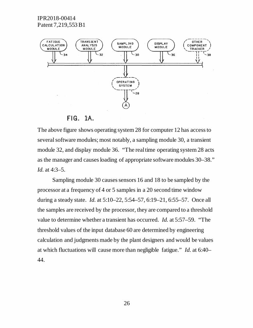
The sampling and analysis computer 12 generally includes the
functional components illustrated in Figure 1A, reproduced below. Ex.
1009, at 2:37–39, Fig. 1A.
IPR2018-00414 Patent 7,219,553 B1
26
The above figure shows operating system 28 for computer 12 has access to
several software modules; most notably, a sampling module 30, a transient
module 32, and display module 36. “The real time operating system 28 acts
as the manager and causes loading of appropriate software modules 30–38.”
Id. at 4:3–5.
Sampling module 30 causes sensors 16 and 18 to be sampled by the
processor at a frequency of 4 or 5 samples in a 20 second time window
during a steady state. Id. at 5:10–22, 5:54–57, 6:19–21, 6:55–57. Once all
the samples are received by the processor, they are compared to a threshold
value to determine whether a transient has occurred. Id. at 5:57–59. “The
threshold values of the input database 60 are determined by engineering
calculation and judgments made by the plant designers and would be values
at which fluctuations will cause more than negligible fatigue.” Id. at 6:40–
44.

IPR2018-00414 Patent 7,219,553 B1
27
If the monitored pressure sample signal exceeds the threshold value,
transient recording starts and continues until a steady state is reestablished
for a predetermined period. Ex. 1009, 5:61–64, 6:35–40, 7:1–5, 7:14–16.
“Transient recording retains a great deal more data than steady state
recording.” Id. at 7:5–6. Rather than receiving 4 or 5 samples over 20
seconds, when transient sampling is triggered, the processor receives 10
samples per second and 200 samples will be kept over the 20 second time
window. Id. at 7:6–14.
“Both the steady state statistics and transients are stored in the
transient and steady state time history database as, for example, a list of
[pressures] and the times at which the [pressures] were recorded.” Id. at
5:65–68; see also 9:5–6. The information stored in the transient and steady
state history database is used as input to the transient analysis module 32,
which computes transient parameters that are provided to a fatigue
calculation software module 34. Id. at 41–50. The computed information
from module 34 is finally provided to the display software module 36, which
displays the information in usable form to an operator. Id. at 50–63.
b. Analysis of Palusamy as Applied to the Claim 1 Claim 1 – Preamble “1. A dynamic transient pressures detection system comprising:”
Petitioner contends that Palusamy discloses the preamble of claim 1
by describing a method and apparatus that “monitor[s] and analyz[es]
fatigue accumulated by components and systems subjected to, among other
things, pressure transients.” Pet. 26 (citing Ex. 1009, 1:8–11; Ex. 1002 ¶
97). Palusamy explains that the disclosed system “continuously monitors
IPR2018-00414 Patent 7,219,553 B1
28
the sensors and records steady-state and transient phenomena.” Id. at 27
(citing Ex. 1009, Abstract, 1:8–11, 3:31–34) (emphasis omitted). Although
Patent Owner does not dispute directly whether this evidence shows
Palusamy’s system detects transient pressures, Patent Owner contends more
generally that the transient pressures the system does detect are not the
claimed “dynamic transient pressures.” See PO Resp. 40–45.
Patent Owner contends that “[d]ynamic transient pressures,’ which
include pressure fluctuations lasting less than one second (under a proper
construction), would go completely undetected in Palusamy’s system.” Id.
at 41. Patent Owner argues that Palusamy’s analysis and sampling of 4 or 5
samples per 20 second window during steady state recording to determine
whether there is a transient pressure makes the system incapable of detecting
the most severe transients, which will have a duration of less than one
second. Id. at 40–42. Notably, however, Patent Owner does not provide any
evidence, or supported technical reasoning, that the system of Palusamy is
capable of only detecting pressure fluctuations caused by a leak in a pipe.
Patent Owner’s arguments do not demonstrate a deficiency with
Petitioner’s evidence, however, because the alleged point of distinction is
not commensurate with the scope of the claim. For the reasons discussed
above in section II(D)(1), the claim phrase “dynamic transient pressure”
does not require a configuration that must at least detect pressure
fluctuations lasting less than one second. Moreover, Patent Owner has not
shown Palusamy’s system can only detect pressure fluctuations caused by a
leak in a pipe.
After reviewing Petitioner’s cited evidence from Palusamy and the
testimony of Mr. Landers, we find that Petitioner has shown persuasively

IPR2018-00414 Patent 7,219,553 B1
29
that Palusamy discloses a “dynamic transient pressures detection system,” as
the preamble of claim 1 recites.
Claim 1 – element (1) “a dynamic transient pressure sensor installed in an operating fluid chamber,”
Petitioner contends that Palusamy discloses element (1) of claim 1.
Pet. 27–28. Petitioner asserts that this limitation is shown by Palusamy’s
description of pressure sensors 16 and 18 and their placement at critical
locations in a fluid pipe to detect pressure transients. Id. (citing Ex. 1009,
3:31–34, 6:1–7, Fig. 5). Petitioner supports its assertion further with
citations to the Lander Declaration. Id. at 24 (citing Ex. 1002 ¶ 98). Beyond
its challenge associated with the meaning of “dynamic transient pressure,”
which we have not accepted, Patent Owner does not separately dispute that
Palusamy discloses element (1) of claim 1. See PO Resp. 40–47.
On this record, having reviewed Petitioner’s contentions and the
evidence cited in support thereof, we find Petitioner has shown persuasively
that Palusamy discloses “a dynamic transient pressure sensor installed in an
operating fluid chamber,” as claim 1 recites.
Claim 1 – element (2) “a transmission system for transferring a signal indicating pressure within the operating fluid chamber to a receiver,”
Petitioner contends that Palusamy discloses element (2) of claim 1.
Pet. 28–30. Petitioner asserts that Palusamy shows this limitation through
its description of a system with a computer 12 that processes (e.g., signal
conditioners, digitizers) signal samples received from pressure sensors 16
IPR2018-00414 Patent 7,219,553 B1
30
and 18. Id. at 25 (citing Ex. 1009, 3:23–64, 4:25–47, 5:18–20, Figs. 1A,
1B). Petitioner supports its contentions further with citations to the Lander
Declaration. Id. at 30 (citing Ex. 1002 ¶¶ 99–100). Patent Owner does not
separately dispute that Palusamy discloses the element (2) of claim 1. See
PO Resp. 40–47.
On this record, having reviewed Petitioner’s contentions and the
evidence cited in support thereof, we find Petitioner has shown persuasively
that Palusamy discloses “a transmission system for transferring a signal
indicating pressure within the operating fluid chamber to a receiver,” as
claim 1 recites.
Claim 1 – element (3) “a clock or timer for recording chronological time detection,”
Petitioner contends that Palusamy discloses element (3) of claim 1.
Pet. 30–32. Petitioner asserts that Palusamy’s description of a system with a
computer 12 that has access to a transient and steady state time history
database 62 that stores the received pressure values and the recording times
of these pressure values shows this limitation. Id. (citing Ex. 1009, 4:41–48,
5:54–6:16, 6:9–16, 7:44–68, 9:5–12, Fig. 6). Petitioner supports its
contentions further with citations to the Lander Declaration. Id. at 30, 32
(citing Ex. 1002 ¶¶ 101–104). Patent Owner does not separately dispute that
Palusamy discloses element (3) of claim 1. See PO Resp. 40–47.
On this record, having reviewed Petitioner’s contentions and the
evidence cited in support thereof, we find Petitioner has shown persuasively
that Palusamy discloses “a clock or timer for recording chronological time
detection,” as claim 1 recites.

IPR2018-00414 Patent 7,219,553 B1
31
Claim 1 – element (4) “a signal processor for receiving signals and recording data, and”
Petitioner contends that Palusamy discloses element (4) of claim 1.
Pet. 32–34. In particular, Petitioner contends that this limitation is disclosed
by Palusamy’s description of a system with a computer using sampling
module 30 that samples pressure sensors 16 and 18 and stores the data for
subsequent processing. Id. (citing Ex. 1009, 5:3–23, Figs. 1A, 1B, 3A, 3B).
Petitioner supports its assertions further with citations to the Lander
Declaration. Id. (citing Ex. 1002 ¶¶ 105–106). Patent Owner does not
separately dispute that Palusamy discloses element (4) of claim 1. See PO
Resp. 40–47.
On this record, having reviewed Petitioner’s contentions and the
evidence cited in support thereof, we find Petitioner has shown persuasively
that Palusamy discloses “a signal processor for receiving signals and
recording data,” as claim 1 recites.
Claim 1 – element (5) “a data management program for analyzing and displaying collected data,”
Petitioner contends that Palusamy discloses element (5) of claim 1.
Pet. 34–35. In particular, Petitioner contends that this limitation is disclosed
by Palusamy’s description of a system with computer 12 that operates
sampling module 30, transient analysis module 32, fatigue calculation
module 34, and display module 36, which together stores, analyzes and
displays transient pressure data. Id. (citing Ex. 1009, 4:41–63, Figs. 1A,
1B). Petitioner supports its contentions further with citations to the Lander
IPR2018-00414 Patent 7,219,553 B1
32
Declaration. Id. at 35 (citing Ex. 1002 ¶¶ 107–108). Patent Owner’s does
not separately dispute that Palusamy discloses element (5) of claim 1. See
PO Resp. 40–47.
On this record, having reviewed Petitioner’s contentions and the
evidence cited in support thereof, we find Petitioner has shown persuasively
that Palusamy discloses “a data management program for analyzing and
displaying collected data,” as claim 1 recites.
Claim 1 – element (6) “wherein the signal processor records data samples showing dynamic transient pressures above a threshold level to internal memory until pressure returns to a steady state or until the user specifies.”
Petitioner contends that Palusamy discloses element (6) of claim 1 by
its description of a system with computer 12 using sampling module 30 that
checks the sampled pressure sensor values against “a threshold value” to
determine whether the data indicates the pressure in a pipe is in a steady
state or transient state condition. Pet. 35 (citing Ex. 1009, 6:35–41).
Palusamy states, “[i]f any monitored . . . pressure . . . signal in the entire
plant exceeds the threshold values stored in the input database 60, transient
recording starts . . . and continues until a steady state is reestablished for a
predetermined period.” Ex. 1009, 6:35–41. Petitioner supports its
contention further with citations to the Lander Declaration. Pet. 35 (citing
Ex. 1002 ¶ 109).
In addition to the alleged deficiency associated with the meaning of
“dynamic transient pressure,” which we have found lacks merit, Patent
Owner contends that Petitioner’s evidence is deficient to show this element

IPR2018-00414 Patent 7,219,553 B1
33
(6) because Palusamy’s system “is limited to detecting whether a measured
pressure average is greater than or less than a threshold magnitude of
pressure, regardless of how long that change takes place.” PO Resp. 46.
Patent Owner argues that Figure 6 of Palusamy “demonstrates that Palusamy
fails to teach threshold level (properly construed), but instead teaches
whether a pressure is above or below a specific pressure value.” Id.
According to Patent Owner, “[m]athematically speaking, comparing one
pressure to another pressure is different than determining a rate of change.”
Id. Patent Owner argues that “Palusamy’s use of the word ‘transient’ refers
to whether pressure is higher or lower than a pressure magnitude threshold,”
which “is insufficient to teach recording transients above a ‘threshold level’
as recited in claim 1.” Id. at 47.
Patent Owner’s arguments do not demonstrate a deficiency with
Petitioner’s evidence because the alleged point of distinction is not
commensurate with the scope of the claim. For the reasons discussed above
in section II(D)(2), the claim phrase “threshold level” does not require a
preset amount for a rate of pressure change. Patent Owner appears to agree,
however, that Palusamy discloses using a preset pressure value to identify
the occurrence of a transient pressure. See PO Resp. 45–46.2
2 Patent Owner argues that Palusamy’s evaluation of whether a transient pressure has occurred is “limited to detecting whether a measured pressure average is greater than or less than a threshold magnitude of pressure, regardless of how long that change takes place.” PO Resp. 46 (emphasis added). We do not agree that the Palusamy disclosure supports Patent Owner’s suggestion that there is no temporal component to Palusamy’s evaluation of whether a transient pressure has occurred. As Patent Owner itself has described the configuration of Palusamy’s system (PO Resp. 40–
IPR2018-00414 Patent 7,219,553 B1
34
After reviewing Petitioner’s cited evidence from Palusamy and the
testimony of Mr. Landers, we find Petitioner has shown persuasively that
Palusamy discloses a “wherein the signal processor records data samples
showing dynamic transient pressures above a threshold level to internal
memory until pressure returns to a steady state or until the user specifies,” as
claim 1 recites.
Therefore, for the foregoing reasons, Petitioner has demonstrated by a
preponderance of the evidence that Palusamy anticipates claim 1 of the ’553
patent.
c. Analysis of Palusamy as Applied to the Claim 2 Claim 2 “2. The detection system of claim 1, wherein the dynamic transient pressure sensor operates continuously without operator interface.”
Petitioner contends Palusamy teaches a “computer-based detection
system ‘acquires, logs and analyzes analog and/or digital signals from
component sensors in a process control plant . . . ,’ and ‘the system continuously monitors the sensors and records steady-state and transient
phenomena.’” Pet. 35–36 (quoting Ex. 1009, Abstract). Petitioner argues
that a “pressure sensor that continuously measures sensor signals in
conjunction with a computer-based detection system does not require an
41), Palusamy makes an evaluation every 20 seconds about whether the 4 or 5 data samples collected indicate the occurrence of a transient pressure. Ex. 1009, 5:54–64, 6:55–7:5. Thus, although the temporal component of Palusamy’s transient detection may not be sufficient to detect transients lasting less than one second, we do not agree that Palusamy evidences that its detection is wholly independent of an amount of change over a period of time.

IPR2018-00414 Patent 7,219,553 B1
35
operator interface.” Id. at 36 (citing Ex. 1002, ¶ 110). Patent Owner does
not dispute that Palusamy discloses the elements of claim 2. See PO Resp.
39–49.
After reviewing Petitioner’s cited evidence from Palusamy and the
testimony of Mr. Landers, we find that Petitioner has shown by a
preponderance of the evidence that Palusamy anticipates claim 2 of the ’553
patent.
d. Analysis of Palusamy as Applied to the Claim 3 Claim 3 “3. The detection system of claim 1, wherein the dynamic transient pressure sensor records an analog signal.”
Petitioner contends that “Palusamy explains that a record of the
analog signals generated by an analog sensor 16 is made inside computer 12
for storage.” Pet. 36 (citing Ex. 1009, 3:23–64). Additionally, Petitioner
contends, “Palusamy explains that inside computer 12, a ‘sampling module
30 stores the data in a predetermined size transient and steady state time
history database 62.’” Id. at 37 (quoting Ex. 1009, 4:41–43; citing Ex. 1002,
¶¶ 111–117). Patent Owner does not dispute that Palusamy discloses the
elements of claim 3. See PO Resp. 39–49.
After reviewing Petitioner’s cited evidence from Palusamy and the
testimony of Mr. Landers, we find that Petitioner has shown by a
preponderance of the evidence that Palusamy anticipates claim 3 of the ’553
patent.
IPR2018-00414 Patent 7,219,553 B1
36
e. Analysis of Palusamy as Applied to the Claim 4 Claim 4 “4. The detection system of claim 3, wherein the signal processor converts the analog signal to digital.”
Petitioner contends Palusamy discloses the elements of claim 4 by
describing that computer 12, through sampling module 30, “manages
digitizers 22 and/or 24 (present in input section 10 of Figure 1A) and
converts the analog signal to a digital one.” Pet. 37 (citing Ex. 1009, 2:43–
44, 3:59–64, 4:25–26, Figs. 1A, 1B; Ex. 1002, ¶¶ 118–119). Patent Owner
does not dispute that Palusamy discloses the elements of claim 4. See PO
Resp. 39–49.
After reviewing Petitioner’s cited evidence from Palusamy and the
testimony of Mr. Landers, we find that Petitioner has shown by a
preponderance of the evidence that Palusamy anticipates claim 4 of the ’553
patent.
f. Analysis of Palusamy as Applied to the Claim 5 Claim 5 “5. The detection system of claim 1, wherein the dynamic transient pressure sensor records a digital signal.”
Petitioner contends Palusamy discloses the elements of claim 5 by
describing that “digital sensor 18 produces a digital signal that passes
through a buffer and counter unit 26 before being recorded in computer 12.”
Pet. 37–38 (citing Ex. 1009, 3:23–64, 4:41–43; Ex. 1002, ¶¶ 120–121).
Patent Owner does not dispute that Palusamy discloses the elements of claim
5. See PO Resp. 39–49.

IPR2018-00414 Patent 7,219,553 B1
37
After reviewing Petitioner’s cited evidence from Palusamy and the
testimony of Mr. Landers, we find that Petitioner has shown by a
preponderance of the evidence that Palusamy anticipates claim 5 of the ’553
patent.
g. Analysis of Palusamy as Applied to the Claim 6 Claim 6 “6. The detection system of claim 1, further comprising additional dynamic transient pressure sensors installed in the operating fluid chamber.”
Referring to Figure 5 of Palusamy, and the description thereof,
Petitioner asserts “Palusamy shows an additional dynamic transient pressure
sensor installed in a fluid chamber.” Pet. 38–39 (citing Ex. 1009, 3:31–36,
3:68–4:3, 6:1–4, Fig. 5; Ex. 1002, ¶¶ 122–124). Patent Owner does not
dispute that Palusamy discloses the elements of claim 6. See PO Resp. 39–
49.
After reviewing Petitioner’s cited evidence from Palusamy and the
testimony of Mr. Landers, we find that Petitioner has shown by a
preponderance of the evidence that Palusamy anticipates claim 6 of the ’553
patent.
h. Analysis of Palusamy as Applied to the Claim 11 Claim 11 “11. The detection system of claim 1, wherein the dynamic pressure sensor contains a predetermined threshold of pressure representing hazards to persons or structures.”
Petitioner contends that three facts from Palusamy’s disclosure
establish the elements of claim 11. Pet. 39–40. First, Palusamy discloses a

IPR2018-00414 Patent 7,219,553 B1
38
pressure sensor. Id. at 39 (citing Ex. 1009, 3:31–34). Second, Palusamy
discloses an input database 60 containing “threshold limits that determine
when a transient has occurred,” which have values determined by technical
calculations and judgments. Id. (citing Ex. 1009, 4:31–34, 6:41–44). Third,
Palusamy shows an appreciation of “the hazards to persons or structures,
particularly with respect to operations in nuclear power plants.” Id. at 40
(citing 1:23–57).
Patent Owner argues that Petitioner’s evidence is deficient to show
anticipation because Petitioner relies on the same evidence offered to show a
“threshold level,” as recited in claim 1, to demonstrate “a predetermined
threshold of pressure representing hazards to persons or structures,” as
recited in claim 11. PO Resp. 48. Patent Owner asserts that Petitioner erred
by treating these separate and distinct limitations as one limitation. Id.
In reply, Petitioner asserts that “predetermined threshold of pressure
representing hazards” should carry its ordinary meaning and be understood
to “simply refer[] to ‘a number stored in memory.’” Pet. Reply 11.
Although we agree with Petitioner that it is appropriate to apply the plain
meaning to the phrase, “a predetermined threshold of pressure representing
hazards to persons or structures,” we disagree “a number stored in memory”
accurately reflects that meaning. The plain meaning requires a preset value
that is indicative of a pressure potentially harmful to persons or structures.
Petitioner fails to offer any evidence that Palusamy discloses a configuration
in which a threshold limit is set to be indicative of a pressure that is
potentially harmful to persons or structures. Petitioner concedes, and we
agree, a “threshold level” and a “predetermined threshold of pressure
representing hazards to persons or structures” are two wholly separate and
IPR2018-00414 Patent 7,219,553 B1
39
distinct limitations. Pet. Reply 11 (“[T]here is no meaningful link between
“predetermined threshold of pressure representing hazards to persons or
structures” and the “threshold level.”). Thus, identifying a threshold used
identifying fatigue is not sufficient.
Notably, Petitioner contends that Palusamy “appreciates the hazards
to persons or structures,” but does not represent Palusamy actually discloses
setting a threshold limit to represent hazards to persons or structures. Pet. 40
(emphasis added). Nor does Petitioner provide any argument or technical
reasoning explaining why a skilled artisan, reading Palusamy, would at once
envisage the system as having a threshold limit set at a value that is
representative of a potentially harmful pressure. See id. The evidence cited
only describes a system focused on gathering information about “the status
of critical plant components and systems with respect to fatigue” and states,
“[t]he threshold values . . . would be values at which fluctuations will cause
more than negligible fatigue.” Ex. 1009, 1:26–30, 6:40–44.
Therefore, after reviewing Petitioner’s cited evidence from Palusamy,
we find that Petitioner has not shown by a preponderance of the evidence
that Palusamy anticipates claim 11 of the ’553 patent.
i. Analysis of Palusamy as Applied to the Claim 12 Claim 12 “12. The detection system of claim 1, wherein the transmission receiver, clock or timer and signal processor are an integrated unit.”
Petitioner contends that the computer 12 with its multiple modules in
Palusamy discloses the elements recited in claim 12. Pet. 40. Petitioner
identifies the computer 12 uses sampling module 30 to store pressure sensor
IPR2018-00414 Patent 7,219,553 B1
40
data in a transient and steady state time history database, “which serves as a
transmission receiver as it receives the transmission of the pressure sensor
data.” Id. (citing Ex. 1009, 4:25–26, 4:41–48). Because the transient and
steady state time history database 62 stores data that includes the time
associated with when it was recorded, Petitioner contends this demonstrates
computer 12 includes a clock or timer. Id. (citing 5:54–6:16, 7:12–26). The
functions served by the different modules operated by computer 12 (e.g.,
sampling module 30, transient analysis module 32, fatigue calculation
module 34) evidence computer 12 includes a signal processor, according to
Petitioner. Id. (citing 4:24–31, 4:48–54, 5:1–7:68, 8:1–10:38, Figs. 1A, 3–
15).
Patent Owner does not dispute Palusamy discloses the signal
processor and transmission receiver as an integrated unit, but argues that
Petitioner has not shown Palusamy “disclose[s] integrating a ‘clock or timer’
with the processor and receiver.” PO Resp. 48. Patent Owner asserts that
Petitioner does not actually point to anything that states a clock or timer is
integrated with computer 12 and, therefore, Petitioner’s contentions are
“merely a guess.” Id. at 48. Patent Owner argues more generally that
having a dedicated clock or timer for each sensor, rather than a centralized
clock or timer, would improve timing accuracy. Id. at 49.
We do not agree with Patent Owner that Petitioner’s evidence requires
us to “guess” about whether computer 12 has a clock or timer. We find
Palusamy’s disclosure of a computer 12 that, through its operation modules,
stores the times at which it records selected sample data, to be compelling
evidence that Palusamy’s computer 12 necessarily includes a clock or timer.
See Ex. 1009, 5:54–68. Notably, Patent Owner does not argue that

IPR2018-00414 Patent 7,219,553 B1
41
Palusamy’s clock or timer would be separate from computer 12 or provide
any other persuasive explanation of why Palusamy’s clock or timer would
satisfy the limitations of claim 12. .
After reviewing the evidence cited from Palusamy by Petitioner, we
find that Petitioner has shown by a preponderance of the evidence that
Palusamy anticipates claim 12 of the ’553 patent.
j. Analysis of Palusamy as Applied to the Claim 14 Claim 14 “14. The detection system of claim 1, wherein at steady state the signal processor records single data samples in a temporary buffer, wherein at steady state the signal processor discards unnecessary data and wherein at steady state the signal processor records single data samples, or a periodic average of data samples, in a permanent buffer at a predetermined periodic interval and wherein the predetermined period interval is user or system defined.”
Petitioner contends Palusamy discloses the elements of claim 14
through the process described for analyzing sample data during steady state
conditions. Pet. 41–44. Petitioner contends it teaches a process that relies
storing samples in temporary memory, which Palusamy also refers to as
“rotating storage.” Pet. 41 (citing Ex. 1009, 5:18–20, 5:59–61). Petitioner
contends that the “[s]amples are stored temporarily in rotating storage for a
time window of predetermined duration, e.g., 20 seconds, after which in
steady state the samples are reduced to a statistic and stored otherwise . . .
[and] [t]he rotating storage is then reused for the next time window.” Id.
(citing Ex. 1009, 5:59–61, 6:55–68, 6:26–28).
Petitioner contends Palusamy “explains that in steady state and in a
twenty-second window, all data, except for only 4 or 5 sample readings of
IPR2018-00414 Patent 7,219,553 B1
42
the pressure sensor, are discarded. Id. at 42 (citing Ex. 1009, 7:5–14; Ex.
1002, ¶¶ 140–142). Petitioner contends Palusamy teaches that, at steady
state, the computer 12 records single data samples and statistical data of the
data samples in permanent storage at predetermined intervals that are
defined by a user or the system for determining a transient or steady state
condition. Id. at 42–44 (citing Ex. 1009, 3:20–24, 5:59–68, 6:55–57, 18:16–
18; Ex. 1002, ¶¶ 143–150.).
Patent Owner does not dispute that Palusamy discloses the elements
of claim 14. See PO Resp. 39–49.
After reviewing the evidence Petitioner cites from Palusamy, we find
that Petitioner has shown by a preponderance of the evidence that Palusamy
anticipates claim 14 of the ’553 patent.
k. Claims 15–18 Claims 15–18 each recite a “means” to perform various functions.
Claim 15 recites a “means to enter and store transient pressure parameters
and transient pressure data.” Ex. 1001, 8:25–26. Claim 16 recites a “means
to compare sample data to transient pressure parameters to identify transient
pressure pressures.” Id. at 8:28–29. Claim 18 recites a “means to analyze
and display collected data, and return data sampling rates and data recording
rates to predetermined rates when sample data returns to non-transient
pressure parameters.” Id. at 8:34–37. The parties do not dispute that these
claim limitations are governed by 35 U.S.C. § 112 ¶ 6.
Patent Owner contends, for the means-plus-function limitations, that
Petitioner cannot meet its burden because it failed to identify in the Petition
the specific portions of the specification that describe the structure, material,

IPR2018-00414 Patent 7,219,553 B1
43
or acts corresponding to each claimed function, as required by 37 C.F.R. §
42.104(b)(3). PO Resp. 59. Petitioner does not dispute that the Petition is
deficient, responding only that:
Petitioner sets forth the following corresponding structures found in the Specification to perform the specified claimed functions in: • Claim 15: signal processor and internal memory; (EX1001 at 3:11-14.) • Claim 16: signal processor; id. • Claim 17: signal processor; id.
Pet. Reply 26. Patent Owner argues that Petitioner’s Reply is improper
because 37 C.F.R. § 42.104(b)(3) requires Petitioner to provide its means-
plus-function analysis in the Petition and because 37 C.F.R. § 42.23(b)
limits the reply to addressing only arguments raised in Patent Owner’s
Response. PO Sur Reply 5.
We agree with Patent Owner, and Petitioner does not dispute, that the
Petition is deficient because it fails to specify portions of the specification
describing the structure, material, or acts corresponding to each claimed
function. Moreover, we agree that Petitioner’s attempt to address this
deficiency in the Reply is improper because it goes beyond responding to
Patent Owner’s arguments which do not address the actual construction of
these terms. PO Resp. 59. Therefore, we do not consider Petitioner’s new,
improperly raised contentions regarding construction of these claim terms.
37 C.F.R. § 42.23(b). Even if we did consider Petitioner’s new contentions,
they would be insufficient. Petitioner identifies alleged corresponding
structures in the ’553 patent, but does not provide any contention concerning
where these structures are disclosed in Palusamy. Pet. Reply. 26.

IPR2018-00414 Patent 7,219,553 B1
44
Because Petitioner has failed to identify sufficient structure for the
means-plus-function limitations, and therefore fails to specify where the
corresponding structure is found in Palusamy, Petitioner has not shown by a
preponderance of the evidence that Palusamy anticipates claims 15, 16, and
18. In addition, because claim 17 depends from claim 16, Petitioner has not
shown by a preponderance of the evidence that Palusamy anticipates claim
17.
2. Obviousness Of Claims 3, 5, 7–11, 13, 14, and 19–21 (Grounds 2–5)
A claim is unpatentable under 35 U.S.C. § 103 if the differences
between the claimed subject matter and the prior art are “such that the
subject matter as a whole would have been obvious at the time the invention
was made to a person having ordinary skill in the art to which such subject
matter pertains.” 35 U.S.C. § 103(a). The question of obviousness under 35
U.S.C. § 103 is resolved on the basis of underlying factual determinations,
including: (1) the scope and content of the prior art; (2) any differences
between the claimed subject matter and the prior art; (3) the level of skill in
the art; and (4) objective evidence of nonobviousness, i.e., secondary
considerations. Graham v. John Deere Co., 383 U.S. 1, 17–18 (1966).
When evaluating claims for obviousness, it is well settled that “the
prior art as a whole must be considered.” In re Hedges, 783 F.2d 1038, 1041
(Fed. Cir. 1986); see also In re Merck & Co., Inc., 800 F.2d 1091, 1097
(Fed. Cir. 1986) (explaining that a reference “must be read, not in isolation,
but for what it fairly teaches in combination with the prior art as a whole”).
“It is impermissible within the framework of section 103 to pick and choose
[teachings] from any one reference ... to the exclusion of other parts
IPR2018-00414 Patent 7,219,553 B1
45
necessary to the full appreciation of what such reference fairly suggests to
one of ordinary skill in the art.” Hedges, 783 F.2d at 1041 (quoting In re
Wesslau, 353 F.2d 238, 241 (CCPA 1965)). In the same vein, invalidity on
the ground of obviousness requires more than establishing that the claim
elements were previously known. As the Court instructs in KSR:
[A] patent composed of several elements is not proved obvious merely by demonstrating that each of its elements was, independently, known in the prior art. Although common sense directs one to look with care at a patent application that claims as innovation the combination of two known devices according to their established functions, it can be important to identify a reason that would have prompted a person of ordinary skill in the relevant field to combine the elements in the way the claimed new invention does.
KSR Int’l Co., 550 U.S. at 418–19.
a. Incorporation by Reference Patent Owner makes a general objection to Petitioner’s unpatentability
arguments based on obviousness (i.e., Grounds 2–9) because the Petition
“presents virtually no analysis showing a reason to combine references and
instead makes conclusory statements while improperly incorporating the
contents of Dr. Lander’s Declaration.” PO Resp. 49–50 (citing Cisco
Systems, Inc. v. C-Cation Tech., LLC., IPR2014-00454, paper 12). We
agree.
It is improper to incorporate by reference arguments from one
document into another document. 37 C.F.R. § 42.6(a)(3). “Th[e] practice of
citing [a] [d]eclaration to support conclusory statements that are not
otherwise supported in the Petition . . . amounts to incorporation by
reference.” Cisco Systems, Inc. v. C-Cation Tech., LLC., IPR2014-00454,

IPR2018-00414 Patent 7,219,553 B1
46
paper 12, at 9. “One purpose of the prohibition against incorporation by
reference is to eliminate abuses that arise from incorporation.” Id. at 10
(citing Rules of Practice for Trials Before The Patent Trial and Appeal
Board and Judicial Review of Patent Trial and Appeal Board Decisions;
Final Rule, 77 Fed. Reg. 48,612, 48,617 (Aug. 14, 2012); DeSilva v.
DiLeonardi, 181 F.3d 865, 866-67 (7th Cir. 1999) (Incorporation “by
reference amounts to a self-help increase in the length of the [] brief[,]” and
“is a pointless imposition on the court’s time. A brief must make all
arguments accessible to the judges, rather than ask them to play archeologist
with the record.”)).
Here, Petitioner has generically identified seven “KSR Factors” that it
alleges are “non-limiting rationales that support a finding of obviousness.”
Pet. 22–23. In the portions of the Petition discussing obviousness (i.e.,
Grounds 2–9), Petitioner does not address specifically any of these factors,
however. Rather, Petitioner cites to the declaration of Dr. Lander and
identifies several different “KSR Factors,” after making a conclusory
statement that a skilled artisan “would know” to combine the references in
the manner claimed. See id. at 52, 54–58, 60–61, 71, 76–77. We note that
Petitioner represents that the Petition is 22 words short of the 14,000 word
limitation. Id. at 80. Allowing Petitioner to incorporate by reference the
numerous additional arguments regarding motivation to combine from Dr.
Lander’s Declaration would serve to circumvent the page limits imposed on
petitions for inter partes review, while imposing on our time by asking us to
sift through and address arguments the Petitioner did not believe were
significant enough to include in the Petition. This is improper. Therefore,
we do not consider the arguments regarding a motivation to combine that are
IPR2018-00414 Patent 7,219,553 B1
47
not made in the Petition, but are instead only incorporated by reference
through citations to Dr. Lander’s Declaration.3
b. Objective Evidence of Nonobviousness Patent Owner argues that evidence of commercial success, licensing,
and industry praise demonstrates the non-obviousness of the claimed
invention. PO Resp. 59. First, for commercial success, Patent Owner
identifies the TP-1 product, which is allegedly marked with the ’553 patent,
as having created an entirely new market for transient detection that has
generated over a million dollars in sales through 10 years. Id. at 61–62
(citing Ex. 2016, ¶¶ 9–12; Ex. 2015, ¶¶ 6–7). Second, for evidence of
licensing, Patent Owner identifies its own license to the ’553 patent, arguing
that it took this license because the “patented system of dynamic pressure
transducers and digital technology to monitor pipelines for indefinite periods
of time” is unique because “the system activates a high speed data recorder
to record the event 100x/second.” Id. at 62 (citing Ex. 2017, ¶¶ 16–17; Ex.
2002). Third, for industry praise, Patent Owner identifies a research paper
wherein the author charactized the TP-1 products as the “best commercially
available unit on the market for the purpose of continuous longterm transient
pressure monitoring of water and wastewater systems” and a report by one
of the users of the TP-1 product who states that “[a] unique feature of the
3 Even if we were to address Dr. Lander’s evaluation of the “KSR Factors,” it would not change the our decision in this case because they rely consistently on conclusory remarks that describe what a skilled artisan could have done once presented with the prior art references, rather than explaining why a skilled artisan would have selected the references and combined them to arrive at the claimed invention.

IPR2018-00414 Patent 7,219,553 B1
48
calibration was the use of transient pressure recorders capable of capturing
dynamic pressure readings up to 1,000 Hz during surge.” Id. at 63 (citing
Ex. 2007, 83; Ex. 2011, 2–3).
In addition, Patent Owner notes that Petitioner has represented that
standard pressure monitors miss “transient spikes” because to detect such
transients a system “[m]ust have a High sample rate,” and that “[s]ample
rates of 1 s/s, 16 s/s or 32 s/s are inadequate.” Id. at 64 (citing Ex. 2008, 46,
48, 53; Ex. 2003, 1 (noting that a high sample rate provides an innovation to
detect pressure transients that are often invisible at lower resolutions).
“[W]hen secondary considerations are present, though they are not
always dispositive, it [would be] error not to consider them.” In re Kao, 639
F.3d 1057, 1067 (Fed. Cir. 2011). We evaluate the strength of Patent
Owner’s evidence, however, by assessing whether it is “reasonably
commensurate with the scope of the claims” and whether it has “a nexus . . .
[to] the merits of the claimed invention.” Id. at 1068. Patent Owner must
establish a connection between its evidence and the claimed invention for it
to have “substantial weight.” Id. How much weight afforded Patent
Owner’s evidence depends on “the degree of the connection between the
features presented in evidence and the elements recited in the claims.”
ClassCo, Inc. v. Apple, Inc., 838 F.3d 1214, 1221 (Fed. Cir. 2016); see
Merck & Cie v. Gnosis S.P.A., 808 F.3d 829, 837 (Fed. Cir. 2015) (“To the
extent that the [Patent Owner] demonstrates the required nexus, [the]
objective evidence of nonobviousness will be accorded more or less
weight.”). For the following reasons, though we find that evidence of
commercial success, licensing, and industry praise present here, we also find
that this evidence is entitled to limited weight.

IPR2018-00414 Patent 7,219,553 B1
49
Patent Owner presents unrebutted evidence that the TP-1 was a
commercialized product that practiced the invention and received some
praise. Patent Owner asserts that the TP-1 was “marketed as an
improvement over prior art solutions because it detects transients that were
undetectable using conventional systems,” but argues that the TP-1 was
successful because “[n]othing prior to the TP-1 was available in the
marketplace” and the TP-1 thus “created a new market, a market for
transient detection.” PO Resp. 61. However, the ’553 patent acknowledges
that prior art systems for detecting transients do, in fact, exist, though it
asserts that prior art systems “continuously record pressure at a constant
rate” and thus “do not have the flexibility to present detailed data concerning
sharp transient pressures.” Ex. 1001, 2:28–35. Patent Owner does not
persuasively tie the alleged commercial success to this allegedly novel
feature of increasing data sampling rates and/or data recording rates during
transient detection, or to any other allegedly novel feature claimed in the
’553 patent.
We also note that Patent Owner merely provides us with some
information about the amount of revenue it has generated without giving any
persuasive contextual information that would allow us to evaluate whether
that amount of revenue is indicative of success or not. See In re Applied
Materials, 692 F.3d 1289, 1299 (Fed. Cir. 2012) (“Just as the number of
units sold without evidence of the market share is only weak evidence of
commercial success, . . . so too is an assertion of market share lacking in
sales data.”).
Regarding the evidence of licensing activity and industry praise, we
accord this evidence limited weight for similar reasons. The praise that the

IPR2018-00414 Patent 7,219,553 B1
50
TP-1 product received, and the alleged reason Patent Owner sought to
license the ’553 patent, was the fact that the configuration of the TP-1
product could detect rapid transients lasting less than one second. The
claimed invention of the ’553 patent, however, covers more broadly
temporary pressure fluctuations lasting both more and less than one second
(see supra II(D)(1)). As a result, the claims are considerably broader than
the particular feature that received praise and motived Patent Owner to
license the ’553 patent. Patent Owner fails to persuasively tie this alleged
evidence to the specific novel features claimed in the ’553 patent that were
not present in the prior art. See ClassCo, 838 F.3d at 1221–22 (“Here,
because [the] claims . . . are considerably broader than the particular features
praised in the articles, it would be reasonable . . . to assign this evidence
little weight.”).
We find the Hiniker case to be instructive for this issue also. In
Hiniker, the specification of the patent highlighted operational advantages
enabled by the claimed invention and the patent owner submitted objective
evidence similarly supportive of the operational advantages, but because
those operational advantages were not a recited part of the claimed
invention, the Federal Circuit did not find the objective evidence to be
commensurate with the claim scope. Hiniker, 150 F.3d at 1368–69. “The
invention disclosed in Hiniker’s written description may be outstanding in
its field, but the name of the game is the claim.” Id. at 1369.
The same is true in this case because the scope of the claims in the
’553 patent are substantially broader than a transient pressure detection
system that detects temporary pressure fluctuations lasting less than one

IPR2018-00414 Patent 7,219,553 B1
51
second. Thus, although we factor into our obviousness analysis Patent
Owner’s objective evidence of nonobviousness, we accord it limited weight.
c. Analysis of Claims 7–9, 13, 20, and 21 in View of Palusamy and Worthington (Ground 2) i. Overview of Worthington
Worthington seeks to provide “a system of autonomous sensors for
the inspection of pipelines, bridges, buildings and other structures.” Ex.
1010, 1:8–10. The general components of the system include the following:
sensors, pre-amplifiers, remote acoustic processors and central acoustic
signal processors. Id. at 1:10–13. Worthington asserts the disclosed system
provides non-destructive testing that identifies and localizes deterioration of
a structure by using a series of sensors to detect and record acoustic
emissions of distress. Id. at 1:60–65. “An important aspect of the invention
is that a transient or sound associated with an indicator of deterioration is
precisely timed at its location of reception.” Id. at 1:55–57.
For example, for a prestressed concrete cylinder pipe in which
hydrophones are inserted in the pipe while the pipe is in use, “[t]he
hydrophones listen for sounds which are consistent with the breaking of the
pre-tensioned reinforcements.” Id. at 2:28–32. Deterioration of the concrete
pipe walls reduces the load-carrying capability of the prestressing wire and
causes the wire to break, which results in energy release, some of which is in
the form of acoustic energy that propagated through the wall of the pipe and
into the column of water within the pipe. Id. at 3:10–19. “Each energy
release propagates a transient acoustic signal through the pipe” and “[t]he
hydrophones detect those acoustic transients.” Id. at 3:22–24. The
hydrophones are “tuned to recognize a significant sound that emanates from
IPR2018-00414 Patent 7,219,553 B1
52
a breaking or moving reinforcement.” Id. at 2:43–45. “The sound of failure
of the prestressed wire is what is used to trigger the sound and time
recordings in the memory.” Id. at 5:34–36.
Co-located with each hydrophone at the data sampling site is a global
position satellite system (“GPS”) receiver that provides precise time of
detection information and exact location information. Id. at 3:25–31. Also
co-located with each hydrophone is a “signal detector/recorder” that
digitizes and analyzes the detected acoustic noise to identify transient signals
that are consistent with criteria established by the system’s human operator.
Id. at 3:34–48. “The sound of failure of the prestressed wire is what is used
to trigger the sound and time recordings in the memory.” Id. at 5:34–36.
The detected data of interest is transferred to a “signal analyzer” for
classification and the data “matching the acoustic signature of structural
deterioration are identified as such.” Id. at 4:7–23. After a signal is
identified as deterioration-related, data from adjacent hydrophones are
evaluated to determine whether the same transient was detected within the
signal-travel-time of the original hydrophone and, if so, computations are
performed to determine the location of origin of the deterioration are
performed. Id. at 4:30–52. As a result, “the location of points of
deterioration are determined, and the purpose of the [system Worthington
discloses] is performed.” Id. at 4:55–56.
ii. Claim 7
Claim 7 “7. The detection system of claim 6, wherein a source of a dynamic transient pressure is determined from the additional dynamic pressure sensors.”

IPR2018-00414 Patent 7,219,553 B1
53
Petitioner contends that the combined teachings of Palusamy and
Worthington teach or suggest the elements of claim 7 for the following
reasons. Palusamy shows “the presence of an additional dynamic transient
pressure sensor,” both of which are located at a respective “critical location.”
Pet. 49 (citing Ex. 1009, 6:1–16, Fig. 5). Palusamy provides an example in
which the system is monitoring the pressure at only one of the “critical
locations,” but because of the known factors about the environment at those
locations, the pressures from a first critical location can be used to calculate
the pressure at another critical location. Id. at 49–50 (citing 6:1–4, 11:1–
12:25, Fig. 5).
Petitioner turns to Worthington’s disclosure of a system that records
soundwaves associated with an indicator of structural deterioration using
multiple sensors (e.g., hydrophones) to detect the origin of the deterioration.
Id. at 50–51 (citing Ex. 1010, 2:5–7, 4:30–48). Worthington teaches that the
sensors “may also include water pressure, water temperature and water
velocity sensors.” Id. at 51 (citing Ex. 1010, 1:14–15, 1:36–37). From these
disclosures, Petitioner concludes,
[a person of skill in the art] would know to combine Palusamy’s teachings of multiple additional dynamic transient pressure sensors and data obtained from such multiple sensors with Worthington’s teachings of using multiple sensor data to determine the source of dynamic transient pressure.
Pet. 52 (citing Ex. 1002, ¶ 166).
Petitioner’s reasoning is unpersuasive to show that a skilled artisan
would have had a rationale to combine Palusamy and Worthington in the
way claim 7 recites. We find Personal Web Techs., LLC v. Apple, Inc., 848
F.3d 987 (Fed. Cir. 2017), to be analogous to the facts before us. In that

IPR2018-00414 Patent 7,219,553 B1
54
case, the Federal Circuit held the Board erred by accepting petitioner’s
rationale that “a person of ordinary skill in the art reading [the prior art]
would have understood that the combination of [the prior art] would have
allowed for the selective access features of [one reference] to be used with
[the other reference’s] content-dependent identifiers feature.” Personal Web
Techs., 848 F.3d at 993. This reasoning was held to “say no more than that a
skilled artisan, once presented with the two references, would have
understood that they could be combined.” Id. “And that is not enough: it
does not imply a motivation to pick out those two references and combine
them to arrive at the claimed invention.” Id. at 993–994 (citing Belden Inc.
v. Berk–Tek LLC, 805 F.3d 1064, 1073 (Fed. Cir. 2015) (“[O]bviousness
concerns whether a skilled artisan not only could have made but would have
been motivated to make the combinations or modifications of prior art to
arrive at the claimed invention.”).
Similarly, here, Petitioner merely makes a conclusory statement that a
skilled artisan “would know” to combine Palusamy and Worthington in the
manner recited to determine the source of a dynamic transient pressure.
Pet. 52. Nothing in Petitioner’s conclusory statement explains why a skilled
artisan would have had reason to combine these two references to arrive at
the claimed invention, however.
When we consider Worthington, as a whole, for what it fairly suggests
to one of ordinary skill in the art, it is clear that it teaches the use of sensors
that are tuned to recognize significant sounds emanating from a structure,
which are indicative of structural deterioration in the structures. Ex. 1010,
Abstract, 1:63–2:4, 2:27–32, 2:43–45, 3:10–24, 4:23–24. Worthington
teaches “[t]he sound of failure . . . is what is used to trigger the sound and

IPR2018-00414 Patent 7,219,553 B1
55
time recordings.” Id. at 5:34–36. For example in the context of
deterioration noises from a prestressed concrete pipe, “the snapping of a
prestressed wire or the grinding noises associated with movement and re-
anchoring of broken ends of the wire are sensed.” Id. at 6:3–8. A
“[s]tructural deterioration is identified in those instances when the signature
of the emission matches the known emission of deterioration.” Id. at 2:2–4,
4:22–23.
Palusamy, on the other hand, teaches using sensors to measure the
working environment in which the structures are operating to determine the
amount stress and fatigue the components have endured. See Ex. 1009,
Abstract, 3:17–22 (“The apparatus and methods described herein . . . can be
applied to any process plant, or even individual components or systems
subject to fatigue loadings due to fluid flow, thermal and pressure
transients.”). In Palusamy, the sensors are placed at selected “critical
locations” to obtain measurements at those locations to provide data for
calculation of fatigue accumulation. See id. at Abstract, 6:3–4.
Thus, while both references may relate to measuring pressure
fluctuations, Worthington teaches measuring fluctuations caused by sounds
emanating from a deteriorating structure and Palusamy teaches measuring
fluctuations caused by the operation of a system. In other words, Palusamy
is concerned with evaluating the operating conditions within a structure,
whereas Worthington is concerned with evaluating the integrity of the
structure itself. Although the principles of physic used by these different
applications are similar, this fact alone fails to explain why a skilled artisan
would have modified how Palusamy applies those principles with the way
Worthington applies them.

IPR2018-00414 Patent 7,219,553 B1
56
Given these difference between the teachings of Palusamy and
Worthington, we do not find Petitioner has shown persuasively why a skilled
artisan would have had reason to combine the teachings of these two
references in a manner that would result in the claimed invention.
Therefore, Petitioner has not shown by a preponderance of the evidence that
claim 7 is unpatentable because it would have been obvious to a skilled
artisan at the time of the invention in view of Palusamy and Worthington.
iii. Claim 8
Claim 8 “8. The detection system of claim 1, wherein data from the dynamic transient pressure sensor identifies the source of a transient pressure.”
Petitioner contends that the combined teachings of Palusamy and
Worthington disclose the elements of claim 8 for the following reasons.
“Palusamy discloses using a dynamic transient pressure sensor to identify a
transient pressure.” Pet. 52. Worthington teaches using the data from a
sensor to facilitate the identification of a transient pressure source. Id.
(citing Ex. 1010, 3:3–24, 2:27–34). Petitioner adds that Worthington’s
sensors measure acoustic transients caused by sounds generated from a
deteriorating structure and use the same principles of physics as the sensors
Palusamy uses to measure pressure transients in the operating fluid. Id. at 54
(citing Ex. 1002, ¶¶ 167–171). From this, Petitioner concludes,
[a person of skill in the art] would know to combine Palusamy’s teachings of collecting transient pressure sensor data with Worthington’s teachings of using the transient pressure sensor data to determine the transient pressure source.
Pet. 54–55 (citing Ex. 1002, ¶¶ 172–173).
IPR2018-00414 Patent 7,219,553 B1
57
Petitioner’s reasoning is unpersuasive to show a reason that a skilled
artisan would have combined Palusamy and Worthington in the way claim 8
recites. Similar to claim 7 above, Petitioner simply makes a conclusory
statement that a skilled artisan “would know” to combine Palusamy and
Worthington in the manner recited to determine the transient pressure
source. Id. Nothing in Petitioner’s conclusory statement implies a
motivation to pick out the two references and combine them to arrive at the
claimed invention, however. See Personal Web Techs., 848 F.3d at 993–
994.
Given the difference between the teachings of Palusamy and
Worthington, as discuss above for claim 7, we do not find Petitioner has
shown persuasively why a skilled artisan would have had reason to pick out
these two references and combine them to have the data from the pressure
sensors of Palusamy be used to identify the source of a transient pressure.
Therefore, Petitioner has not shown by a preponderance of the evidence that
claim 8 is unpatentable because it would have been obvious to a skilled
artisan at the time of the invention in view of Palusamy and Worthington.
iv. Claim 9
Claim 9 “9. The detection system of claim 8, wherein the source of a dynamic transient pressure is identified as a point of diversion of fluid from the operating fluid chamber, and wherein unknown or illegal diversions are identified.”
Because claim 9 depends from claim 8, which has not been shown to
be unpatentable (see supra II(E)(2)(c)(iii)), Petitioner has not shown by a
preponderance of the evidence that claim 9 is unpatentable.
IPR2018-00414 Patent 7,219,553 B1
58
v. Claim 13
Claim 13 “13. The detection system of claim 1, wherein the clock or timer is a Global Positioning System receiver for obtaining and sending geographic location of the instrument and time of detection to a signal processor.”
Petitioner contends that the combined teachings of Palusamy and Worthington disclose the elements of claim 13 for the following reasons.
Palusamy discloses a system that has both a dynamic transient pressure
sensor and a clock or timer. Pet. 56. Worthington teaches using a global
position satellite system (“GPS”) co-located with each sensor as a clock or
timer to determine the precise time of detection and the exact location of the
sensor by sending its signals to a signal processor. Id. (Ex. 1010, 1:14–15,
1:41–44, 3:25–31, 4:15–17). Petitioner contends these facts disclose “a GPS
for sending geographic location of the sensors and time of detection to a
signal processor.” Id. at 57 (citing generally Ex. 1002, ¶¶ 178–184). As a
result, Petitioner concludes,
[a person of skill in the art] would know to combine data from Palusamy’s sensor, which identifies transient pressures, with Worthington’s teachings of using GPS for sending geographic location of the sensors and time of detection to a signal processor [and] . . . would know to combine Palusamy’s teachings of using a clock or timer with Worthington’s teachings of using a GPS, as a clock or timer, for obtaining and sending geographic location of the sensor and time of detection to a signal processor.
Id. (citing Ex. 1002, ¶¶ 185–186).
Petitioner’s reasoning is unpersuasive to show a reason that a skilled
artisan would have combined Palusamy and Worthington in the way claim
IPR2018-00414 Patent 7,219,553 B1
59
13 recites. Petitioner simply makes a conclusory statement that a skilled
artisan “would know” to combine Palusamy and Worthington in the manner
recited. Id. Nothing in Petitioner’s conclusory statement implies a
motivation to pick out the two references and combine them to arrive at the
claimed invention, however. See Personal Web Techs., 848 F.3d at 993–
994.
Given the differences between Palusamy and Worthington, as
discussed above for claim 7, we do not find Petitioner has shown
persuasively why a skilled artisan would have had reason to modify
Palusamy’s sensors to have GPS co-located with each sensor as a clock or
timer to determine the precise time of detection and the exact location of the
sensor. Palusamy teaches a system that has an “input database 60 [that]
contains: . . . component identification information, including sensor
locations.” Ex. 1009, 4:31–36. Palusamy places its sensors at selected
“critical locations” to obtain measurements at those specific locations to
provide data for calculation of fatigue accumulation at those locations. See
id. at Abstract, 6:3–4. It is unclear, and Petitioner has not persuasively
shown, why a skilled artisan would have had a need to locate GPS at each of
the sensors to determine its location.
In addition, Palusamy teaches a host computer that records the times
at which the pressures were record (Ex. 1009, 5:65–68), thus it is unclear,
and Petitioner has not persuasively shown, why a skilled artisan would have
had reason to locate GPS at each of the sensors to determine the time of
detection of the transient pressures. Therefore, Petitioner has not shown by
a preponderance of the evidence that claim 13 is unpatentable because it
IPR2018-00414 Patent 7,219,553 B1
60
would have been obvious to a skilled artisan at the time of the invention in
view of Palusamy and Worthington.
vi. Claim 20
Claim 20 “20. The detection system of claim 1, wherein background noise is removed from the signals at the signal processor.”
Petitioner contends that the combined teachings of Palusamy and
Worthington disclose the elements of claim 20 for the following reasons.
Palusamy has a signal processor and Worthington “explains that the signal
processor is used to remove the background noise.” Pet. 57 (citing Ex. 1009,
5:3–23; Ex. 1010, 7:21–30, 7:43–44, 5:65–67; Ex. 1002, ¶¶ 187–188). From
this, Petitioner concludes,
[a person of skill in the art] would know to combine Palusamy’s teachings of using a signal processor with Worthington’s teachings to remove background noise from the signals (at the signal processor).
Pet. 57–58 (citing Ex. 1002, ¶ 189).
Petitioner’s reasoning is unpersuasive to show that a skilled artisan
would have had a rationale to combine Palusamy and Worthington in the
way claim 20 recites. Petitioner simply makes a conclusory statement that a
skilled artisan “would know” to combine Palusamy and Worthington in the
manner recited. Id. Nothing in Petitioner’s conclusory statement implies a
rationale to pick out the two references and combine them to arrive at the
claimed invention, however. See Personal Web Techs., 848 F.3d at 993–
994.
As Patent Owner argues (PO Resp. 53), Worthington teaches a system
that uses sensors to detect sounds associated with the deterioration of a
IPR2018-00414 Patent 7,219,553 B1
61
structure and filters background noise from the sounds of interest to facilitate
the evaluation of the recorded sound. Ex. 1010, 2:58–3:24, 3:39–42, 4:22–
23, 5:34–36, 5:49–56, 7:22–26, 8:11–16. “Those matching the acoustic
signature of structural deterioration are identified as such.” Ex. 1010, 4:22–
23.
Palusamy, on the other hand, teaches detecting a transient pressure by
averaging sample data over a sample window and comparing the derived
average to a threshold value. Ex. 1009, 5:54–64. As Patent Owner argues
persuasively, this averaging of data over a time window “smoothens out the
data so that outliers and other fluctuations are removed.” PO Resp. 53
(citing Ex. 2005, 87:12–24). Petitioner contends that this argument “ignores
Palusamy’s disclosure regarding data integrity check 86, which identifies the
need for ensuring that only data within an ‘allowable range’ is processed.”
Pet. Reply 25 (citing Ex. 1009, 5:23–27, 5:46–47). But Palusamy teaches
that the integrity check is performed to “to assure the sensors are working
properly” by checking whether a reading is within the “allowable sensor
ranges.” Ex. 1009, 5:22–27. “The allowable ranges are determined by the
laws of nature and the capacities of the plant.” Id. at 5:27–28. Additionally,
Palusamy teaches that the integrity check can compare the values from
multiple kinds of sensors to determine whether “an inconsistency exists.”
Id. at 5:41–51. Thus, Petitioner’s reliance on Palusamy’s “integrity check”
is unpersuasive.
Given the difference between the teachings of Palusamy and
Worthington, we do not find Petitioner has shown persuasively why a skilled
artisan would have had reason to modify Palusamy to have background
noise removed from the pressure signals at the signal processor. Therefore,
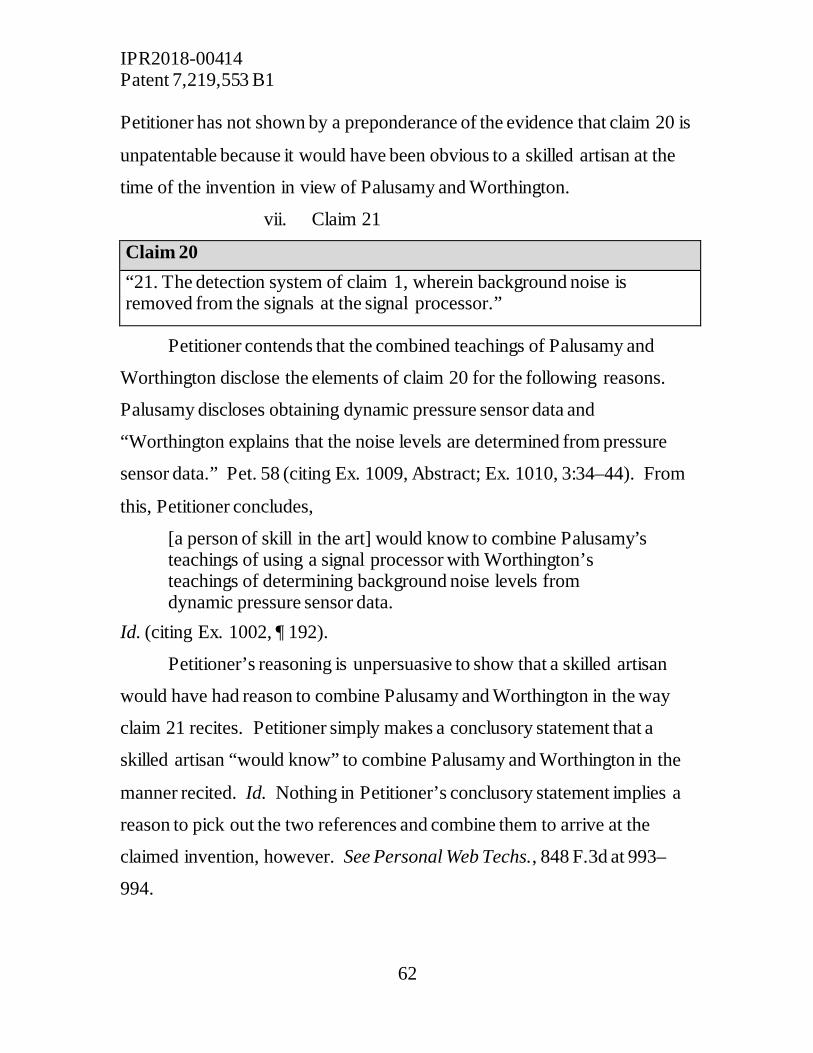
IPR2018-00414 Patent 7,219,553 B1
62
Petitioner has not shown by a preponderance of the evidence that claim 20 is
unpatentable because it would have been obvious to a skilled artisan at the
time of the invention in view of Palusamy and Worthington.
vii. Claim 21
Claim 20 “21. The detection system of claim 1, wherein background noise is removed from the signals at the signal processor.”
Petitioner contends that the combined teachings of Palusamy and
Worthington disclose the elements of claim 20 for the following reasons.
Palusamy discloses obtaining dynamic pressure sensor data and
“Worthington explains that the noise levels are determined from pressure
sensor data.” Pet. 58 (citing Ex. 1009, Abstract; Ex. 1010, 3:34–44). From
this, Petitioner concludes,
[a person of skill in the art] would know to combine Palusamy’s teachings of using a signal processor with Worthington’s teachings of determining background noise levels from dynamic pressure sensor data.
Id. (citing Ex. 1002, ¶ 192).
Petitioner’s reasoning is unpersuasive to show that a skilled artisan
would have had reason to combine Palusamy and Worthington in the way
claim 21 recites. Petitioner simply makes a conclusory statement that a
skilled artisan “would know” to combine Palusamy and Worthington in the
manner recited. Id. Nothing in Petitioner’s conclusory statement implies a
reason to pick out the two references and combine them to arrive at the
claimed invention, however. See Personal Web Techs., 848 F.3d at 993–
994.
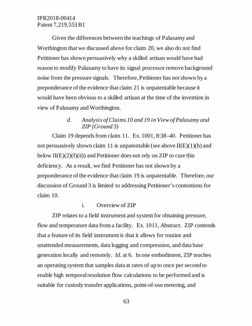
IPR2018-00414 Patent 7,219,553 B1
63
Given the differences between the teachings of Palusamy and
Worthington that we discussed above for claim 20, we also do not find
Petitioner has shown persuasively why a skilled artisan would have had
reason to modify Palusamy to have its signal processor remove background
noise from the pressure signals. Therefore, Petitioner has not shown by a
preponderance of the evidence that claim 21 is unpatentable because it
would have been obvious to a skilled artisan at the time of the invention in
view of Palusamy and Worthington.
d. Analysis of Claims 10 and 19 in View of Palusamy and ZIP (Ground 3)
Claim 19 depends from claim 11. Ex. 1001, 8:38–40. Petitioner has
not persuasively shown claim 11 is unpatentable (see above II(E)(1)(h) and
below II(E)(2)(f)(ii)) and Petitioner does not rely on ZIP to cure this
deficiency. As a result, we find Petitioner has not shown by a
preponderance of the evidence that claim 19 is unpatentable. Therefore, our
discussion of Ground 3 is limited to addressing Petitioner’s contentions for
claim 10.
i. Overview of ZIP
ZIP relates to a field instrument and system for obtaining pressure,
flow and temperature data from a facility. Ex. 1011, Abstract. ZIP contends
that a feature of its field instrument is that it allows for routine and
unattended measurements, data logging and compression, and data base
generation locally and remotely. Id. at 6. In one embodiment, ZIP teaches
an operating system that samples data at rates of up to once per second to
enable high temporal resolution flow calculations to be performed and is
suitable for custody transfer applications, point-of-use metering, and
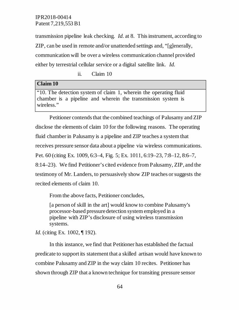
IPR2018-00414 Patent 7,219,553 B1
64
transmission pipeline leak checking. Id. at 8. This instrument, according to
ZIP, can be used in remote and/or unattended settings and, “[g]enerally,
communication will be over a wireless communication channel provided
either by terrestrial cellular service or a digital satellite link. Id.
ii. Claim 10
Claim 10 “10. The detection system of claim 1, wherein the operating fluid chamber is a pipeline and wherein the transmission system is wireless.”
Petitioner contends that the combined teachings of Palusamy and ZIP
disclose the elements of claim 10 for the following reasons. The operating
fluid chamber in Palusamy is a pipeline and ZIP teaches a system that
receives pressure sensor data about a pipeline via wireless communications.
Pet. 60 (citing Ex. 1009, 6:3–4, Fig. 5; Ex. 1011, 6:19–23, 7:8–12, 8:6–7,
8:14–23). We find Petitioner’s cited evidence from Palusamy, ZIP, and the
testimony of Mr. Landers, to persuasively show ZIP teaches or suggests the
recited elements of claim 10.
From the above facts, Petitioner concludes,
[a person of skill in the art] would know to combine Palusamy’s processor-based pressure detection system employed in a pipeline with ZIP’s disclosure of using wireless transmission systems.
Id. (citing Ex. 1002, ¶ 192).
In this instance, we find that Petitioner has established the factual
predicate to support its statement that a skilled artisan would have known to
combine Palusamy and ZIP in the way claim 10 recites. Petitioner has
shown through ZIP that a known technique for transiting pressure sensor

IPR2018-00414 Patent 7,219,553 B1
65
data gathered from a pipeline was through a wireless transmission system.
Id. Thus, the modification of Palusamy would be simply substituting one
known technique for transmitting pressure data for another known technique
for doing the exact same thing. “[I]f a technique has been used to improve
one device, and a person of skill in the art would recognize that it would
improve similar devices in the same way, using the technique is obvious
unless its actual application is beyond his or her skill.” KSR Int’l Co.
Teleflex Inc., 550 U.S. 398, 417 (2007).
On this record, and having considered the totality of the evidence,
including Patent Owner’s evidence regarding secondary considerations, we
determine Petitioner has shown by a preponderance of the evidence that
claim 10 is unpatentable because it would have been obvious to a skilled
artisan at the time of the invention in view of Palusamy and ZIP.
e. Analysis of Claim 14 in View of Palusamy and McCracken (Ground 4)
Petitioner contends that the combined teachings of Palusamy and
McCracken disclose the elements of claim 14. However, we have already
found that Palusamy alone discloses the elements of claim 14 (see supra
II(E)(1)(j)). For the same reasons discussed above, we find that Petitioner
has made a persuasive showing that Palusamy teaches or suggests all
elements of claim 14. Considering the totality of the evidence, including
Patent Owner’s evidence regarding secondary considerations, we determine
Petitioner has shown by a preponderance of the evidence that claim 14 is
unpatentable as obvious over Palusamy and McCracken.
IPR2018-00414 Patent 7,219,553 B1
66
f. Analysis of Claims 3, 5, and 11 in View of Palusamy and Kurisu (Ground 5)
Petitioner contends that the combined teachings of Palusamy and
Kurisu disclose the elements of claims 3 and 5. However, we have already
found that Palusamy alone discloses the elements of claims 3 and 5 (see
above II(E)(1)(d) and II(E)(1)(f)). For the same reasons discussed above, we
find that Petitioner has made a persuasive showing that Palusamy and Kurisu
teach or suggest all elements of claims 3 and 5. Considering the totality of
the evidence, including Patent Owner’s evidence regarding secondary
considerations, we determine Petitioner has shown by a preponderance of
the evidence that claims 3 and 5 are unpatentable as obvious over Palusamy
and McCracken.
Claim 11, the only remaining claim challenged under Ground 5, is
addressed below.
i. Overview of Kurisu
Kurisu “relates to pipeline breakage sensing systems for rapidly
sensing a pipeline breakage or damaged location and supporting a rapid
recovery therefrom.” Ex. 1013, 1:7–10, 2:23–25. Kurisu discloses installing
a plurality of pressure sensors installed on pipelines of a pipe network, such
as a water pipe network. Id. at 2:28–30. Kurisu teaches that “[i]f If a leak is
caused in a pipeline conveying a fluid by breakage or the like, then the
pressure abruptly decreases and a negative pressure wave is generated,”
which is a known phenomenon. Id. at 3:3–6. “By sensing this, a leak can be
found substantially concurrently with occurrence of the leak.” Id. at 3:6–7.
Kurisu discloses that respective sensors sense changes of physical situations
of fluid in a pipeline cause by occurrence of a leak and, in the case of a

IPR2018-00414 Patent 7,219,553 B1
67
pressure sensor, a pressure wave generated by a sudden drop of pressure
when the occurrence of a leak is sensed. Id. at 4:14–18. The leak
information is collected into a “leak information accumulator,” which
“procures pipeline connection information from [a] map manager 28,
summarizes presumption results of the sensors 10, determines the final leak
location and leak quantity, issues a command to an alarm generator 88, and
transfers information to the map manager 28.” Id. at 11:14–24.
ii. Claim 11
Claim 11 “11. The detection system of claim 1, wherein the dynamic pressure sensor contains a predetermined threshold of pressure representing hazards to persons or structures.”
Petitioner contends that the combined disclosures of Palusamy and
Kurisu teach or suggest the elements of claim 11 for the following reasons.
Palusamy discloses dynamic transient pressure sensors for avoiding hazards
to persons and structures. Pet. 76 (citing 1009, 1:23–57, 3:31–36). Kurisu
“discloses a series of operational steps that are carried out inside a sensor
and the difference between measurement at two sequential intervals is
compared to a predetermined threshold inside the sensor. Id. (citing 1013,
9:28–32, Fig. 7; Ex. 1002, ¶¶ 218–219). From this, Petitioner concludes,
[a person of skill in the art] would know to modify Palusamy’s disclosure of dynamic transient pressure sensor used for avoiding hazards to persons and property to contain predetermined threshold of pressure, as taught by Kurisu.
Id. (citing Ex. 1002, ¶ 220).
Patent Owner contends that Petitioner’s argument is deficient because
it “fail[s] to analyze the claims as requiring a ‘threshold level’ that is

IPR2018-00414 Patent 7,219,553 B1
68
separate from the ‘predetermined threshold of pressure [representing hazards
to persons or structures].’” PO Resp. 54. Patent Owner argues Petitioner
has not shown how Kurisu adds anything more to what Palusamy already
discloses in this regard. Id.
We credit Petitioner’s argument that a skilled artisan, at a very general
level, may read Palusamy as disclosing the use of pressure sensors in a way
that could potentially avoid hazards to persons and structures. Nevertheless,
Petitioner’s evidence does not persuade us that Palusamy teaches
configuring sensors to contain a predetermined threshold of pressure
representing hazards to persons or structures. Petitioner has not identified
any persuasive evidence in which Palusamy discloses establishing a
predetermined threshold of pressure representing hazards to persons or
structures. Instead, Palusamy describes a system that is focused on
gathering information about “fatigue” and that states, “[t]he threshold values
. . . would be values at which fluctuations will cause more than negligible
fatigue.” Ex. 1009, 1:26–30, 6:40–44 (emphasis added).
Kurisu teaches sensors that identify pressure changes associated with
leaking pipes (Ex. 1013, 4:14–18), and Petitioner cites Kurisu merely to
show its sensors can detect leaks by having a predetermined threshold and
comparing measurements against the threshold. See Pet. 76. Although
Kurisu teaches sensors containing threshold values to identify leaks in a
pipe, Petitioner offers no evidence that Kurisu suggests setting an additional
threshold value to identify pressures that may be hazardous.
Finally, Petitioner provides no rationale with a rational underpinning
to explain why as skilled artisan would have modified the sensors of
Palusamy to contain a predetermined threshold of pressure representing
IPR2018-00414 Patent 7,219,553 B1
69
hazards to persons or structures in addition to the threshold levels the system
uses to identify transient pressures. Instead, Petitioner simply makes a
conclusory statement that a skilled artisan “would know” to combine
Palusamy and Kurisu in the manner claim 11 recites. Id. Nothing in
Petitioner’s conclusory statement, however, implies a rationale to pick out
the two references and combine them to arrive at the claimed invention. See
Personal Web Techs., 848 F.3d at 993–994. Therefore, Petitioner has not
shown by a preponderance of the evidence that claim 11 is unpatentable
because it would have been obvious to a skilled artisan at the time of the
invention in view of Palusamy and Kurisu.
g. Analysis of Claims 1–6, 11–12, and 14–18 in View of Palusamy and McCracken (Ground 6)
Petitioner contends “[i]f Palusamy is found not to anticipate claim 1,
then McCracken may be used to cure any deficiency.” Pet. 77. Petitioner
only provides additional evidence from McCracken regarding the claim
element “wherein a signal processor records data samples showing dynamic
transient pressures above a threshold level to internal memory until pressure
returns to a steady state or until the user specifies,” which is only found in
claim 1. See id. at 77–78. For claims 2–6, 11–12, and 14–18, Petitioner
merely states regarding these claims that “combining Palusamy and
McCracken renders these claims obvious in an analogous manner.”
Because we have already found that Palusamy alone discloses every
element of claim 1, including the one specifically called out by Petitioner
(see above II(E)(1)), and because Petitioner has expressly made Ground 6 a
contingent one that only applies “[i]f Palusamy is found not to anticipate
claim 1, we do not reach the merits of Ground 6.

IPR2018-00414 Patent 7,219,553 B1
70
h. Grounds 7–9 Petitioner contends,
To the extent claims 2-21 are all dependent on claim 1, then curing the deficiency in claim 1 identified above with respect to Ground 6 also cures the resulting deficiency in the dependent claims. Thus, the combination of Palusamy, McCracken, and Worthington renders claims 7-9, 13, and 20-21 obvious (Ground 7), the combination of Palusamy, McCracken, and Zip renders claims 10 and 19 obvious (Ground 8), and the combination of Palusamy, McCracken, and Kurisu renders claims 3, 5, and 11 obvious (Ground 9).
Pet. 78–79. Petitioner provides no further analysis or argument.
The above contentions—which provide that grounds 7–9 apply only
“[t]o the extent” we find “the deficiency in claim 1 identified above with
respect to Ground 6”—make clear that Grounds 7–9 also are contingent on a
finding that Palusamy does not anticipate claim 1. In view of our finding
that Palusamy does, in fact, anticipate claim 1, there is no deficiency to cure.
Accordingly, we do not reach the merits of Grounds 7–9.
3. Summary Conclusions of Petitioner’s Unpatentability Challenges of Claims 1–21
Petitioner has shown by a preponderance of evidence that claims 1–6,
10, 12, and 14 of the ’553 patent are unpatentable. Petitioner has not shown
by a preponderance of the evidence that claims 7–9, 11, 13, and 15–21 are
unpatentable.
F. Patent Owner’s Motion to Amend
Patent Owner has filed a contingent motion to amend the ’553 patent.
PO MTA 1. Patent Owner seeks to amend the ’553 patent by substituting
proposed claim 22 for issued claims 1, claim 23 for issued claim 13, and
claim 24 for issued claim 14, all “contingent upon a finding of

IPR2018-00414 Patent 7,219,553 B1
71
unpatentability with respect to the original challenged claims.” Id. Because
we have determined that issued claims 1 and 14 are unpatentable, but not
issued claim 13, only proposed claims 22 and 24 are before us.
Patent Owner contends that proposed claims 22 and 24 narrow the
scope of their corresponding issued claims by adding limitations directed to
the detection of fast transient pressures having a duration of less than one
second. Id. at 3–4. Proposed claims 22 and 24 recite:4
[22.P]A dynamic transient pressure detection system comprising:
[22.1] a dynamic transient pressure sensor installed in an operating fluid chamber at a test site, wherein the dynamic transient pressure sensor is configured to detect at least dynamic transient pressures having a duration of less than one second,
[22.2] a transmission system for transferring a signal signals indicating pressure within the operating fluid chamber to a receiver,
[22.3] a clock or timer for recording chronological time detection,
[22.4] a signal processor for receiving the signals and recording data in a temporary buffer, wherein the data recorded in the temporary buffer comprises data samples of the signals at a high sample rate, the high sample rate being faster than one sample per second, and [22.5] a data management program for analyzing and displaying collected data,
[22.6] wherein, based on the data samples in the temporary buffer stored at the high sample rate, the signal
4 In the proposed claims, material deleted from the issued claims is shown by strike-through or double-brackets and material added to the issued claims is shown by underlining. See 37 C.F.R. §§ 1.121(c)(2), 42.121(b).
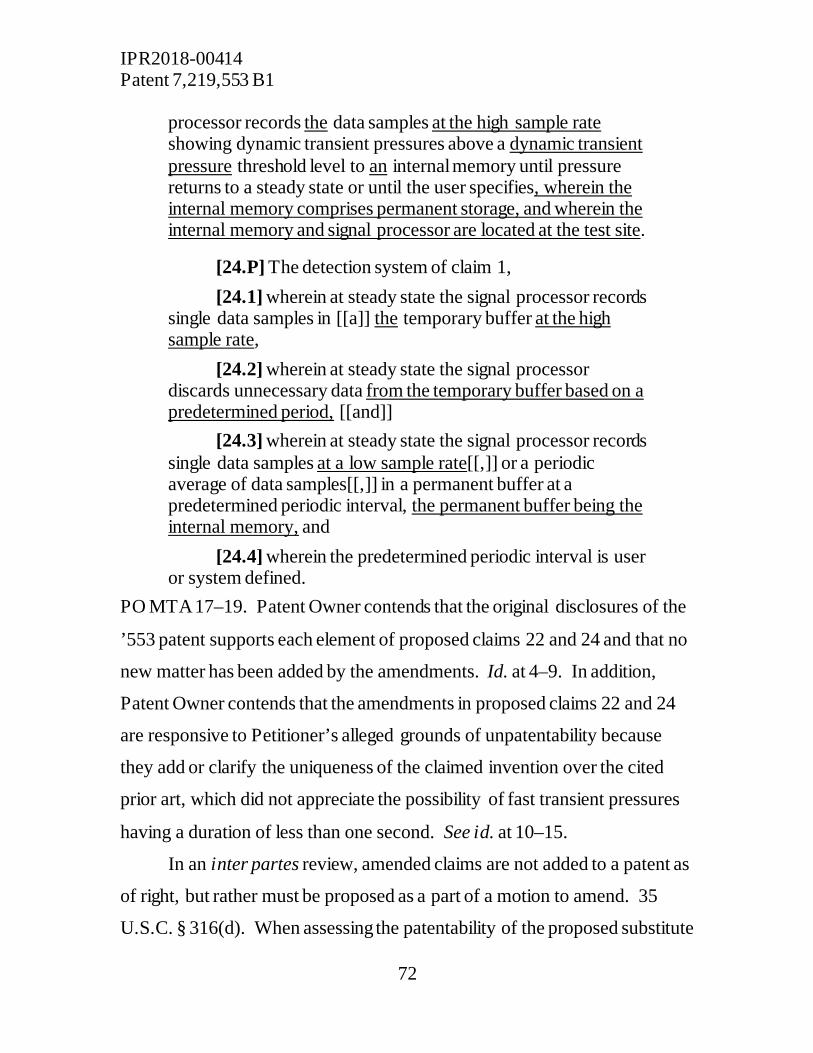
IPR2018-00414 Patent 7,219,553 B1
72
processor records the data samples at the high sample rate showing dynamic transient pressures above a dynamic transient pressure threshold level to an internal memory until pressure returns to a steady state or until the user specifies, wherein the internal memory comprises permanent storage, and wherein the internal memory and signal processor are located at the test site.
[24.P] The detection system of claim 1, [24.1] wherein at steady state the signal processor records
single data samples in [[a]] the temporary buffer at the high sample rate,
[24.2] wherein at steady state the signal processor discards unnecessary data from the temporary buffer based on a predetermined period, [[and]]
[24.3] wherein at steady state the signal processor records single data samples at a low sample rate[[,]] or a periodic average of data samples[[,]] in a permanent buffer at a predetermined periodic interval, the permanent buffer being the internal memory, and
[24.4] wherein the predetermined periodic interval is user or system defined.
PO MTA 17–19. Patent Owner contends that the original disclosures of the
’553 patent supports each element of proposed claims 22 and 24 and that no
new matter has been added by the amendments. Id. at 4–9. In addition,
Patent Owner contends that the amendments in proposed claims 22 and 24
are responsive to Petitioner’s alleged grounds of unpatentability because
they add or clarify the uniqueness of the claimed invention over the cited
prior art, which did not appreciate the possibility of fast transient pressures
having a duration of less than one second. See id. at 10–15.
In an inter partes review, amended claims are not added to a patent as
of right, but rather must be proposed as a part of a motion to amend. 35
U.S.C. § 316(d). When assessing the patentability of the proposed substitute

IPR2018-00414 Patent 7,219,553 B1
73
claims, “the burden of persuasion ordinarily will lie with the petitioner to
show that any proposed substitute claims are unpatentable by a
preponderance of the evidence.” Lectrosonics, Inc. v. Zaxcom, Inc., Case
IPR2018-01129, slip op. at 4 (PTAB Feb. 25, 2019) (Paper 15)
(precedential). Before we evaluate the patentability of Patent Owner’s
proposed substitute claims, we first must consider whether the proposed
claims satisfy the threshold statutory and regulatory requirements set forth in
35 U.S.C. § 316(d) and 37 C.F.R. § 42.221. Id. at 4–10. Accordingly,
Patent Owner must demonstrate (1) the amendment responds to a ground of
unpatentability involved in the trial; (2) the amendment does not seek to
enlarge the scope of the claims of the patent; (3) the amendment proposes a
reasonable number of substitute claims; and (4) the amendment does not
introduce new subject matter and has written description support in the
original disclosure. Id.
Petitioner does not argue that Patent Owner’s proposed amendments
are unreasonable in number, non-responsive to the alleged grounds of
unpatentability, or enlarge the scope of the claims. See Pet. Opp. MTA 1–
25. We agree that Patent Owner has complied with these requirements.
Patent Owner proposes only one substitute claim to replace each challenged
claim, which is presumptively reasonable. 37 C.F.R. § 42.121(a)(3) (A
reasonable number of substitute claims, by rebuttable presumption, is “one
substitute claim . . . to replace each challenged claim.”). We agree with
Patent Owner that the amendments proposed to claims 22 and 24 serve to
narrow issued claims 1 and 14, respectively, by adding limitations without
removing any substantive limitations. Finally, we agree Patent Owner’s
amendments address an issue that was central to Petitioner’s alleged grounds

IPR2018-00414 Patent 7,219,553 B1
74
of unpatentability––namely, whether Palusamy discloses a system
configured to detect fast transient pressures having a duration of less than
one second.
Petitioner argues, however, that Patent Owner’s motion to amend
should be denied because proposed claims 22 and 24 introduce new matter
that lacks written description support in the original disclosure and because
Palusamy anticipates the claims.5 Pet. Opp. MTA 5–24. In addition,
Petitioner alleges claim 22 is indefinite because it combines two separate
statutory classes of invention. Id. at 24–25. We address each argument in
turn below.
1. Claims 22 and 24 Do Not Introduce New Matter A motion to amend “may not . . . introduce new matter.” 35 U.S.C. §
316(d)(3). New matter is any matter that lacks support in the original
application. See TurboCare Div. of Demag Delaval Turbomach. v. General
Elec. Co., 264 F.3d 1111, 1118 (Fed. Cir. 2001) (“When [an] applicant adds
a claim . . . the new claim[] . . . must find support in the original
specification.”). A proposed claim that introduces new matter is properly
rejected under 35 U.S.C. § 112 for lack of written description. See, e.g., In re
Rasmussen, 650 F.2d 1212, 1214 (CCPA 1981) (“The proper basis for
rejection of a claim amended to recite elements thought to be without
support in the original disclosure, therefore, is § 112, first paragraph . . . .”).
Thus, a proposed claim does not introduce new matter when the written
description in the original application “reasonably conveys to those skilled
5 Although the headings in Petitioner’s brief state that the substitute claims are “either anticipated or rendered obvious” by the prior art, Petitioner’s argument relies solely on anticipation. See Pet. Opp. MTA 20–24.
IPR2018-00414 Patent 7,219,553 B1
75
in the art that the inventor had possession of the claimed subject matter as of
the filing date.” Ariad Pharms., Inc. v. Eli Lilly & Co., 598 F.3d 1336, 1351
(Fed. Cir. 2010) (en banc). For this reason, our Rules require a motion to
amend to set forth “[t]he support in the original disclosure of the patent for
each claim that is added or amended.” 37 C.F.R. § 42.121(b)(1).
Patent Owner identifies on an element-by-element basis specific
portions of the original disclosures for the ’553 patent where written
description support can be found for proposed claims 22 and 24. PO MTA
5–9. After reviewing these cited portions of the ’553 patent’s original
disclosure, we find the proposed amendments are supported by the written
description and no new matter has been added.
Petitioner argues that the written description support in the original
disclosures6 for the ’553 patent is deficient for the following amendments,
which are all found in proposed claim 22: (1) “wherein the dynamic
transient pressure sensor is configured to detect at least dynamic pressures
having a duration of less than one second”; (2) “the high sample rate being
faster than one sample per second”; and (3) “test site”. Pet. Opp. MTA 6–
20. We disagree for the following reasons.
6 Petitioner generally cites to the ’553 Patent specification and not the originally filed Specification for U.S. Application No. 10/927,120 because “there is no meaningful difference between the originally filed Specification and the ’553 Patent specification.” Pet. Opp. MTA 6 n. 3. Accordingly, we will do the same.

IPR2018-00414 Patent 7,219,553 B1
76
a. “wherein the dynamic transient pressure sensor is configured to detect at least dynamic pressures having a duration of less than one second”
Petitioner argues Patent Owner’s evidence of written description
support for “wherein the dynamic transient pressure sensor is configured to
detect at least dynamic pressures having a duration of less than one second”
is insufficient because the specification of ’553 patent discloses many
different possible ranges and descriptions for the pressure fluctuation
duration, “i.e., does not find blaze marks that single out particular trees,” which would not allow a skilled artisan “to immediately discern the
less-than-one-second limitations.” Id. at 16–17 (citing Purdue Pharma L.P.
v. Faulding Inc., 230 F.3d 1320, 1326 (Fed. Cir. 2000); see id. 6–14). The
specification of the ’553 patent specifically discloses that a dynamic
pressure sensor may be configured to detect “the most severe transient
pressures,” some of which “will have a duration of less than one second.”
Ex. 1001, 3:18–24, 2:38–41. In addition, as Petitioner concedes, the ’553
patent specification illustrates an example in which the configuration of the
pressure sensors of the preferred embodiment is such that a transient
pressure having a duration of .5 seconds is detected, which is a dynamic
pressure having a duration of less than one second. Ex. 1001, 6:29–39,
Fig.1; see Pet. Opp. MTA 7–9. We find this evidence from the specification
of ’553 patent sufficient to show the inventor actually invented the invention
claimed. Ariad Pharms., 598 F.3d at 1352 (“[T]he written description
requirement does not demand either examples or an actual reduction to
practice; a constructive reduction to practice that in a definite way identifies
the claimed invention can satisfy the written description requirement.”).

IPR2018-00414 Patent 7,219,553 B1
77
Petitioner’s argument does not have merit because the claim language
does not include details that do not appear in the written description. Similar
to Synthes USA, LLC v. Spinal Kinetics, Inc., “[t]he written-description
question here is the familiar one involving whether the claim language is
simply too broad given the disclosure—notwithstanding that claim language
may be and commonly is broader than described embodiments, as it
identifies what aspects of the disclosed embodiments matter.” 734 F.3d
1332, 1346 (Fed. Cir. 2013). Here, Petitioner essentially argues that the
proposed amendment broadly covers “dynamic pressures having a duration
of less than one second,” whereas the specification only discloses a dynamic
pressure having a duration of about .5 seconds. Pet. Opp. MTA 7–9. We
find that a skilled artisan would immediately recognize that the exemplary
embodiment could detect dynamic pressures having a duration of less than
one second and, thus, the differences between the embodiment disclosed and
what is more broadly claimed are immaterial. See Synthes USA, 734 F.3d at
1347.
b. “the high sample rate being faster than one sample per second”
Petitioner argues Patent Owner’s evidence of written description
support for “the high sample rate being faster than one sample per second” is
insufficient “[f]or substantially similar reasons” argued for “wherein the
dynamic transient pressure sensor is configured to detect at least dynamic
pressures having a duration of less than one second.” Pet. Opp. MTA 17.
Therefore, we likewise find Petitioner’s argument unpersuasive for
substantially similar reasons discussed above (see supra II(F)(1)(a)).

IPR2018-00414 Patent 7,219,553 B1
78
c. “test site” Petitioner’s argument regarding “test site” is perplexing. Petitioner’s
challenge to the sufficiency of the written description for this proposed
amendment derives from the specification of the ’553 patent “not draw[ing]
a distinction between a test site and an operating site (of an ‘operating fluid
chamber’) and it is difficult to discern what is meant by a ‘test site.’” Pet.
Opp. MTA 19. It is unclear what relevance this has to a written description
analysis, moreover, Petitioner does not argue “test site” is indefinite.
Regardless, we find Petitioner’s argument to lack merit. As Petitioner
recognizes, the specification of the ’553 patent describes the pressure
sensors as being located at specific locations with respect to an operating
fluid chamber when measurements are taken, which it refers to as a “test
site.” Ex. 1001, 4:18–20, 4:37–40, 6:12–24); Pet. Opp. MTA 18–19. We
find this evidence from the specification of ’553 patent, therefore, shows the
inventor actually invented the invention claimed.
2. Petitioner Has Not Shown Claims 22 and 24 Are Unpatentable
Petitioner argues that Palusamy anticipates proposed claims 22 and
24. Pet. Opp. MTA 21–24. Petitioner contends that Palusamy’s teachings
regarding a high-speed digitizer with a typical sampling rate of about
200,000 samples per second, as well as the use of a 10 samples per second
sampling rate during transient state, disclose proposed claim elements 22.4
and 24.1. See id. at 21–22 (citing Ex. 1009, 3:51–53, 7:12–14; Ex. 1016, ¶¶
65–71, 84–88). We are not persuaded, however.
Respective claim elements 22.4 and 24.1 recite,
IPR2018-00414 Patent 7,219,553 B1
79
[22.4] a signal processor for receiving the signals and recording data in a temporary buffer, wherein the data recorded in the temporary buffer comprises data samples of the signals at a high sample rate, the high sample rate being faster than one sample per second; [24.1] wherein at steady state the signal processor records single data samples in [[a]] the temporary buffer at the high sample rate
PO MTA 17–18. Proposed claim elements 22.4 and 24.1 are similar in that
they both require a signal processor to record sensor signal data in a
temporary buffer at a high sample rate, which is a rate faster than one sample
per second. Petitioner contends that the relevant temporary buffer in
Palusamy is its “rotating storage 90.” Pet. Opp. MTA 22 (citing Ex. 1009,
6:21–28; 5:18–22). Palusamy describes “rotating storage 90” as a “data log
. . . of steady state data.” Ex. 1009, 26–28.
Petitioner’s argument for proposed claim elements 22.4 and 24.1 fails
to specifically address the amended language proposed and clearly show
how Palusamy discloses the added limitations. Pet. Opp. MTA 21–22.
Instead, Petitioner identifies the fact that Palusamy discloses sensors that
may be sampled at a rate of between 10 and 200,000 samples per second,
which is clearly faster than one sample per second. Id. Petitioner contends
Palusamy discloses that the sampling rate is the same for both steady and
transient states operation and that a sampling rate at even the lower 10
sample per second is sufficient to detect pressure fluctuations lasting less
one second. Id.
Petitioner’s argument for proposed claim elements 22.4 and 24.1 does
not show persuasively that, in Palusamy, the signal processor records the
data samples in a temporary buffer at a high sample rate. Even assuming

IPR2018-00414 Patent 7,219,553 B1
80
Petitioner has shown that Palusamy discloses sampling the sensors at a high
sampling rate, which is sufficient to detect pressure fluctuations lasting less
one second, we find Petitioner has not shown that the signal processor in
Palusamy records the sensor sample data in the rotating storage (i.e.,
temporary buffer) at a high sample rate.
Palusamy discloses that its signal processor has two modes of
recording––steady state recording and transient state recording. “Transient
recording retains a great deal more data than steady state recording.” Ex.
1009, 7:5–6. “Data is sampled and collected for a time window of
preferably 20 seconds for each sensor.” Id. at 6:19–21 (emphasis added).
During steady state recording, “4 or 5 samples [are] collected [for a 20
second window]” from the sensors and compared to a threshold level that
determines whether a transient has occurred. Id. at 5:54–59 (emphasis
added). Rotating storage is updated as long as the sensor values of the
steady state recordings are within the defined threshold range. Id. at 5:59–
60, 6:61–68. On the other hand, if the sensor values of the steady state
recordings are outside the defined threshold range, then the signal processor
switches from steady state recording to transient recording. Id. at 7:1–5.
During transient recording, the signal processor begins “high speed
recording” and the “rotating storage is not updated as in the steady state case
and all samples get stored.” Id. at 7:45–49. “[R]ather than 4 or 5 datapoints
being kept [for a 20 second window] as in steady state recording, hundreds
of data points are kept.” Id. at 7:9–11. Once the signal values during
transient recording stay within the threshold range for a period of time, “high
speed recording would stop . . . and resumption of the updating of rotating
storage would occur” (i.e., steady state recording resumes). Id. at 7:57–61.
IPR2018-00414 Patent 7,219,553 B1
81
In view of Palusamy’s description of the disclosed system, we find that it
does not disclose a signal processor that records sensor sample data in the
rotating storage (i.e., a temporary buffer) at a high sample rate, which is a
rate faster than one sample per second. We find that Palusamy discloses a
system in which the signal processor only receives and records sampled
sensor data during steady state conditions at a rate slower than one sample
per second.
We do not find Dr. Lander’s declarations in support of Petitioner’s
contention that the signal processor in Palusamy records sensor sample data
in a temporary buffer at a high sample rate to be persuasive. Pet. Opp. MTA
21–22 (citing Ex. 1016, ¶¶ 65–71, 84–88). His testimony relies on an
interpretation of Palusamy that is inconsistent with what it actually teaches,
which Dr. Lander admits. See Ex. 2005, 98:16–99:23, 101:20–102:11,
106:3–107:13. Nor do we find claim 2 of Palusamy to be persuasive
evidence that the signal processor of Palusamy records sensor sample data in
a temporary buffer at a high sample rate. Claims 2 depends from claim 1
and states, in relevant part,
sampling at a sampling rate and storing sensor samples in a storage at a first storage rate if the sensor signal is within the first threshold range . . . sampling at the sampling rate and storing sensor samples in the storage at a second higher storage rate than the first storage rate if the sensor signal is equal to or outside the first threshold range limit values, whereby the transient is detected.
Ex. 1009, 18:16–23. Although this claim may suggest sampling a sensor at
the same rate during both steady and transient states, it does suggest that a
signal processor receives or records the sampled data at the same rate during
both states. Palusamy teaches that the sampling of the sensors occurs in the
IPR2018-00414 Patent 7,219,553 B1
82
hardware portion of Palusamy’s system consisting of the signal input section
10, which is independent of and before computer 12 ever collects or records
sensor sample data. For example, Palusamy teaches:
Once the [sampled] signals are processed through the buffer and counter unit 26 in the case of digital signals, or through the low speed digitizer 22 or high speed digitizer 24 in the case of analog signals, the signals are properly digitized and ready for input into the computer 12.
Ex. 1009, 3:59–64, Fig. 1 (emphasis added). Palusamy teaches that, if in a
steady state, computer 12 collects (i.e., receives and records) 4 or 5 of the
available samples per 20 second window and, if in a transient state,
computer 12 collects all of the available samples for the 20 second window.
Id. at 5:54–64, 7:5–14. “Transient data is recorded at a higher sampling rate,
so that the parameters of the transients, such as the maximum value, can be
determined for stress analysis.” Id. at 2:22–24. Thus, when claim 2 of
Palusamy is viewed in the context of its specification, we find that a skilled
artisan would understand claim 2 to teach a computer that receives and
records sensor sample data at a slower rate during steady state conditions
than it receives and records sensor sample data during transient state
conditions. Petitioner, thus, has not shown persuasively that claim 2 of
Palusamy discloses at least the proposed claim elements 22.4 and 24.1.
Therefore, for the foregoing reasons, we find Petitioner has not proven
by a preponderance of the evidence that proposed claims 22 and 24 are
unpatentable in view of Palusamy.
3. Petitioner Has Not Shown Claims 22 Is Indefinite Petitioner argues that proposed claim 22 is indefinite because it recites
“until the user specifies,” which Petitioner contends prevents a skilled

IPR2018-00414 Patent 7,219,553 B1
83
artisan from knowing with reasonable certainty the scope of the subject
matter claimed. Pet. Opp. MTA 24–25 (citing IPXL Holdings, LLC v.
Amazon.com, Inc., 430 F.3d 1377 (Fed. Cir. 2005)). We agree with Patent
Owner that the proposed “claim language ‘until a user specifies’ is a
condition reflecting the system’s capabilities, not a method step that needs to
be performed in order to practice the invention.” PO Reply MTA 5; see
UltimatePointer, L.L.C. v. Nintendo Co., Ltd., 816 F.3d 816, 827 (Fed. Cir,
2016) (“[u]nlike IPXL and similar cases, the claims at issue here make clear
that the ‘generating data’ limitation reflects the capability of that structure
rather than the activities of the user.”). Therefore, we find Petitioner has not
proven by a preponderance of the evidence that proposed claim 22 is
indefinite.
4. Summary Conclusions for Patent Owner’s Motion to Amend
Because Patent Owner has shown proposed claims 22 and 24 meet the
statutory requirements of 35 U.S.C. § 316(d) and the procedural
requirements of 37 C.F.R. § 42.221, and Petitioner has not shown
persuasively that these claims are unpatentable, we grant Patent Owner’s
Motion to Amend.
G. Patent Owner’s Unopposed Motion to Seal
Patent Owner requests that we seal Exhibit 2015 due to the inclusion
of business information that Patent Owner regards as confidential. Paper 21.
Petitioner has not opposed Patent Owner’s request. There is a strong public
policy in favor of making information filed in an inter partes review open to
the public, especially because the proceeding determines the patentability of
claims in an issued patent and, therefore, affects the rights of the public. See

IPR2018-00414 Patent 7,219,553 B1
84
Garmin Int'l, Inc. v. Cuozzo Speed Techs., LLC, Case IPR2012-00001
(PTAB Mar. 14, 2013) (Paper 34). Under 35 U.S.C. § 316(a)(1) and 37
C.F.R. § 42.14, the default rule is that all papers filed in an inter partes
review are open and available for access by the public; a party, however,
may file a concurrent motion to seal and the information at issue is sealed
pending the outcome of the motion. It is, however, only “confidential
information” that is protected from disclosure. 35 U.S.C. § 316(a)(7); see
Office Patent Trial Practice Guide, 77 Fed. Reg. 48,756, 48,760 (Aug. 14,
2012). The standard for granting a motion to seal is “for good cause.” 37
C.F.R. § 42.54(a). The party moving to seal bears the burden of proof in
showing entitlement to the requested relief, and must explain why the
information sought to be sealed constitutes confidential information. 37
C.F.R. § 42.20(c).
In reviewing the Exhibit, we conclude that it may contain confidential
information. We are persuaded that good cause exists to have the redacted
portions remain under seal, and the Motion to Seal is granted. Patent
Owner’s Motion to Seal represents that the parties agree to the Board’s
default protective order set forth in the Office Patent Trial Practice Guide.
The Board’s default protective order is hereby entered in this proceeding.
The Office Patent Trial Practice Guide provides:
Expungement of Confidential Information: Confidential information that is subject to a protective order ordinarily would become public 45 days after denial of a petition to institute a trial or 45 days after final judgment in a trial. There is an expectation that information will be made public where the existence of the information is referred to in a decision to grant or deny a request to institute a review or is identified in a final written decision following a trial. A party seeking to

IPR2018-00414 Patent 7,219,553 B1
85
maintain the confidentiality of information, however, may file a motion to expunge the information from the record prior to the information becoming public. § 42.56. The rule balances the needs of the parties to submit confidential information with the public interest in maintaining a complete and understandable file history for public notice purposes. The rule encourages parties to redact sensitive information, where possible, rather than seeking to seal entire documents.
77 Fed. Reg. at 48761.
Consequently, 45 days from entry of this Decision, all information
subject to a protective order will be made public by default. In the interim,
Patent Owner may file a motion to expunge any such information that is not
relied upon in this Decision. See 37 C.F.R. § 42.56.
III. CONCLUSION
We have reviewed the Petition, Patent Owner’s Response, Petitioner’s
Reply, Patent Owner’s Sur-Reply, and Petitioner’s Sur-Reply. We have
considered all of the arguments made by Petitioner and Patent Owner, as
well as all of the evidence cited both for and against the patentability of the
challenged claims, and have weighed and assessed the entirety of this
evidence as a whole.
For the reasons discussed in § II.E.1, supra, we are persuaded that
Petitioner has demonstrated by a preponderance of evidence that claims 1–6,
12, and 14, but not claims 11 and 15–18, of the ’553 patent are unpatentable
in view of Palusamy. For the reasons discussed in § II.E.2.c, supra, we are
not persuaded that Petitioner has demonstrated by a preponderance of
evidence that claims 7–9, 13, 20, and 21 of the ’553 patent are unpatentable
over Palusamy and Worthington. For the reasons discussed in § II.E.2.d,
supra, we are persuaded that Petitioner has demonstrated by a preponderance

IPR2018-00414 Patent 7,219,553 B1
86
of evidence that claim 10, but not claim 19, of the ’553 patent is
unpatentable over Palusamy and ZIP. For the reasons discussed in §
II.E.2.e, supra, we are persuaded that Petitioner has demonstrated by a
preponderance of evidence that claim 14 of the ’553 patent is unpatentable
over Palusamy and McCracken. For the reasons discussed in § II.E.2.f,
supra, we are persuaded that Petitioner has demonstrated by a preponderance
of evidence that claims 3 and 5, but not claim 11, of the ’553 patent are
unpatentable over Palusamy and Kurisu. For the reasons discussed in §
II.E.2.g and II.E.h, supra, we do not reach the merits of Grounds 6–9
because Petitioner expressly makes these Grounds contingent upon a finding
that Palusamy does not anticipate claim 1.
Because we find claims 1 and 14 of the ’553 patent to be unpatentable,
we have also reviewed and considered Patent Owner’s Motion to Amend to
substitute proposed claims 22 and 24 for unpatentable claims 1 and 14, as well
as Petitioner’s Opposition to the Motion to Amend, and Patent Owner’s Reply
to the Opposition.
For the reasons discussed in § II.F, supra, we find proposed claims 22
and 24 have not been shown to be unpatentable, and grant Patent Owner’s
Motion to Amend as to those claims.
For the reasons discussed in § II.G, supra, we find good cause exists to
have the redacted portions of Ex. 2015 remain under seal, and grant Patent
Owner’s Motion to Seal.
IPR2018-00414 Patent 7,219,553 B1
87
IV. ORDER
Accordingly, it is
It is ORDERED that claims 1–6, 10, 12, and 14 of the ’553 patent are
unpatentable;
FURTHER ORDERED that Patent Owner’s Motion to Amend is
granted as claims 1 and 14, such that claim 1 is replaced with substitute
claim 22 and claim 14 is replaced with substitute claim 24;
FURTHER ORDERED that the Motion to Seal is granted;
FURTHER ORDERED that the Board’s default protective order is
entered in this proceeding;
FURTHER ORDERED that the confidential version of Exhibit 2015
is sealed; and
FURTHER ORDERED that because this Decision is final, a party to
this proceeding seeking judicial review of the Decision must comply with
the notice and service requirements of 37 C.F.R. § 90.2.

IPR2018-00414 Patent 7,219,553 B1
88
For PETITIONER:
Ben Bedi ECOTECH LAW GROUP, P.C. [email protected] For PATENT OWNER: Vivek Ganti Greg Ourada HILL, KERTSCHER & WHARTON, LLP [email protected] [email protected]