tribological design constraints of marine renewable - eprints soton
TRANSCRIPT
1
Tribological design constraints of marine
renewable energy systems
Robert J.K. Wood1*, AbuBakr S. Bahaj
2, Stephen R. Turnock
3, Ling Wang
1 and Martin Evans
1.
1national Centre for Advanced Tribology at Southampton (nCATS), School of Engineering Sciences,
University of Southampton, Highfield, Southampton, SO17 1BJ, UK. 2Sustainable Energy Research Group, School of Civil Engineering and the Environment, University of
Southampton, Highfield, Southampton, SO17 1BJ, UK 3Fluid Structure Interactions Research Group, Froude Building, School of Engineering Sciences, University
of Southampton, Southampton, SO17 1BJ, UK *Corresponding author.
Abstract Against the backdrop of increasing energy demands, the threat of climate change and dwindling
fuel reserves, finding reliable, diverse, sustainable/renewable, affordable energy resources has become a priority for many countries. Marine energy conversion systems are at the forefront of providing such a resource. Most marine renewable energy conversion systems require tribological components to covert wind or tidal streams to rotational motion for generating electricity while wave machines typically use oscillating hinge or piston within cylinder geometries to promote reciprocating linear motion. This paper looks at the tribology of three green marine energy systems, offshore wind, tidal and wave machines. Areas covered include lubrication and contamination, bearing and gearbox issues, biofouling, cavitation erosion, tribocorrosion, condition monitoring as well as design trends and loading conditions associated with tribological components. Current research thrusts are highlighted along with areas needing research as well as addressing present day issues related to the tribology of offshore energy conversion technologies. Keywords: off-shore wind, wave, tidal, turbines, energy conversion, corrosion, wear, bearings, gearboxes antifouling, tribocorrosion.
1 Introduction Utilising natural sources for the delivery of energy is currently at the forefront in many of the world energy
policies. Most emphasis is directed towards the generation of large scale electricity production. In addition, the response to the global recession with its many stimuli packages initiated by various governments around the world has resulted in appreciable financial incentives to massively expand renewable energy projects.
The drive behind the global activities in renewable energy stems from the need to reduce emissions, achieve some level of security of supply and economic growth (the generation of new industries, jobs etc.). Many countries are offering incentives to its industry to allow their governments to reach specific targets that will not only aid emission reduction requirements but also help in achieving the security of supply goals. The EU for instance, has a mandatory 20% target for energy production from renewable resources by 2020, with a UK’s share negotiated of 15%. Furthermore, the UK has its own national target of achieving 10% of its electricity production by 2010 which is unlikely to be reached. As a result of the experience with the latter and to avoid missing the EU mandatory and new UK government legislative targets, there is now a huge emphasis in expanding off-shore wind generated electricity.
In offshore wind development, the UK is currently the leading market in the world, with a total installed operational capacity of around 700MW, over 1,000MW under construction and a further 3,500MW been approved or consented. The UK legislative process for this technology is to embark on specific targeted competitive calls or “rounds” to develop potential sites around the UK. The last call “round 3” is estimated to develop a 32,200MW of capacity by 2020 (four times the total capacity under rounds 1 and 2) and represents an investment of around £100 billion from developers (private sector). Such a target is extremely ambitious especially in the current financial difficulties and the lack of appropriate manufacturing capacity in the UK (and overseas) and infrastructure (ports, grid, ships, etc.) to deliver such an expansion.
Electricity from off-shore wind can be augmented by other marine resources. The oceans around the world (and specifically around the UK) offer large renewable energy resources that are yet to be tapped. Wave and tidal energy although only representing a part of the total ocean energy, are recognised as a suitable resource for sustainable

2
generation of electrical power. There is a growing interest around the world in the utilisation of marine or ocean energy resources for the production of large sustainable electrical power. Both wave and tidal resources are large but with variable intensity. As with most forms of renewable resources, wave and tidal energy is unevenly distributed over the globe. For example, this is evidenced by the development of tidal current energy schemes such as the 300 – 812 MW in Korean waters, the Bay of Fundy, Canada (6.6MW), Paimpol-Behat, France (4MW), West Bengal, India (4 MW), Pentland Firth, Anglesey, UK (80.5 MW), and Pouto, New Zealand (200MW). The projected timescales for most of these projects are within 5 to 10 years and demonstrate considerable confidence in the technology. Although the tidal and wave conversion technologies are at their infancy, the exploitation of these resources is seen to have a minimal environmental and visual impact and will contribute to reductions in carbon emissions.
Waves and currents (ocean energy converters) in the ocean could offer one of the least damaging methods
for large-scale electricity generation with no serious conflict over land use. However, compared to off-shore wind which now standardised to 3-bladed turbine and considered mature, there is limited technical knowledge of large scale deployment and operation of the technology. There are also competing designs of conversion technologies, which in many cases need optimisation of the primary conversion philosophy undertaken. For example, (a) the design of the rotors or hydraulic systems (and components) in marine current turbines or wave machines respectively, (b) their use in the saline environments, (c) organisation of the conversion devices in fields or arrays (Myers & Bahaj, 2005, Bahaj & Myers, 2004) and (d) the assimilation of their integration with the electrical network. Hence, in order to verify the use of such energy converters, any research must be encompassing and take into account the various components that will make this technology cost effective – deployment, operation and maintenance. At Southampton University (www.energy.soton.ac.uk) and elsewhere (www.emec.org.uk) there are now such research programmes which will undoubtedly result in a better understanding of ocean energy technology.
Research into resource management, such as the possible impacts on the site by the generators (Garrett & Cummins 2007); the interactions between devices in arrays or farms (Blunden & Bahaj, 2007, Blunden et al., 2008, Blunden & Bahaj, 2008); the effect of turbulence, wave and velocity profiles on the performance of devices (Myers & Bahaj, 2008, Myers et al., 2008). In the area of wave energy resource assessment, research has been focused on effectively processing satellite altimetry data to give robust estimates of wave resource with error bounds (Mackay, 2010a & 2010b).
Fundamental research and development are the backbone of both generating new knowledge and assessing devices at their early stage of development. Hence, in parallel with the developments in the commercial sector, many aspects of wave and tidal current energy conversion remain active areas of research. As highlighted above, this research divides naturally between fundamental understanding; research on individual devices; device interactions and resource assessment. In the first and second categories are the tests of the University of Strathclyde 2.5 m CoRMaT contra-rotating turbine (Clarke et al., 2008). The University of Southampton has carried out extensive tests on side-by-side dual 0.8 m rotors, as part of a UK, Technology Strategy Board funded programme to determine wake interactions; (Myers & Bahaj, 2009). Several teams are working on CFD simulations of tidal turbines, using a variety of methods, linked to experimental results (Bahaj et al., 2007, Mason-Jones et al., 2008, Baltazar & Falçao de Campos, 2008). In wave energy there are also new developments such as those of the Anaconda (Chaplin et al., 2007) and the OWEL devices (Leybourne et al., 2009). The fundamental work on both is being carried out at the University of Southampton.
All these conversion devices have moving parts, subjected to wear and corrosion and the need to operate for a long time in an extremely harsh environment with long maintenance periods and hence it is important to have an understanding of the their tribological issues. The aim of this paper is to highlight current research thrusts and identify areas needing research as well as addressing some of the issues related to the tribology of off-shore energy conversion technologies.
.
2 Offshore wind turbines
With the increase in demand for power generation, the size of blades (rotor radius R) has increased dramatically. This has resulted in the stresses on associated components being magnified and specifically the tribological components of wind turbines have been adversely affected. The shaft power is proportional to R
2 but probably more important to the tribological components is the torque which is
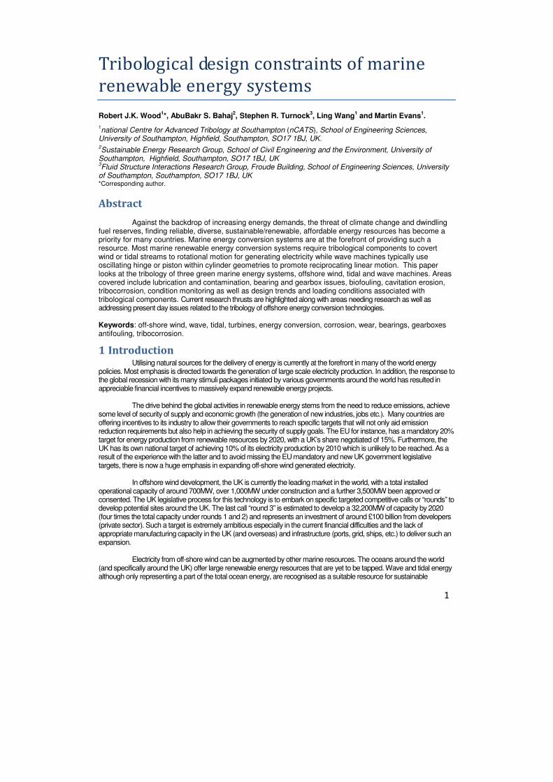
proportional to R3. Figure 1 shows the recent trends in rotor diameter (2R) size and associated power
output. Currently 10 MW machines are being designed but the blade materials required for the 145 m rotor diameter need carbon fibre composite technology to withstand the blade loads rather than the glass fibre composite technology currently used for smaller blade lengths. The actual weight (gravitational) of the blades themselves dominates over inertial loads at this size of machine. In an interesting development
3
some 60 m blades are available based on bamboo fibres in resin. These biomimetic blades have the required stiffness and strength but are ‘green’ as they are based on sustainable material and offer turbine manufacturers a lighter blade option with cheaper blade production routes compared to carbon fibre based systems, (Platts, 2006). Blades rotate up to 10
7 cycles during their life so fatigue resistance needs to be
high.
While the EU research on wind turbine has been concentrated on the demonstration of technology, the UK research has been concentrated on the technological challenges related to the exploitation of the UK’s extensive offshore wind resources. Research is aiming to improve the efficiency and reliability of wind energy, reduce the cost of energy production, facilitate the sitting of machines in off-shore locations and reduce the impact on existing infrastructure. Condition monitoring of wind turbines has been highlighted as a way to improve reliability and reduce maintenance costs and will be covered later in the paper. Although the estimated life of wind turbines is about 20 years, compared to conventional steam turbine generator units that have averaged 40 years of life, the failure rate of wind turbines is about 3 times higher than that of conventional generators due to the fluctuation of the wind source (Tavner et al., 2006, Rasmussen et al., 2004, Musial et al., 2007). Therefore, reliability is essential to the success of wind energy systems and this demands good tribological designs and practice to be in place.
0
2
4
6
8
10
12
14
16
18
20
1985 1990 1995 2000 2005 2010 2015
Year
Ro
tor
dia
mete
r d
ivid
ed
by 1
0 (
m)
or
Po
wer
ou
tpu
t (M
W)
Rotor Diameter (m)
Power output (MW)
Figure 1: Increase in rotor diameter of wind turbines over the past 25 years and the power output from such turbines. Statistical reports from wind turbine manufacturers and from the literature show between 25-70% of wind turbine downtime is due to major component failure. Gearboxes are not the only major component, so gearbox failures are somewhere below these figures while 60-85% of wind turbine gearbox failures are due to bearing failures. The bearings suffer mainly due to the ever increasing bearing sizes and extremely high loads. Currently, several of the components in wind turbines are suffering from poor tribology that severely reduces their lifetimes. The additional cost of providing unexpected maintenance and/or repair to wind turbine systems significantly affects the cost of wind energy as a whole and undermines the reputation of this green energy source to produce reliable energy.
3 Tidal turbines
Tidal or marine currents, with peak flows of over 2 m/s, generated by constrained topography, offer a route for reliable energy extraction. A wide variety of different designs are being studied for marine current energy conversion although most are based on an underwater horizontal axis tidal turbine (HATT) concept, as for example the marine current turbine (Fraenkel, 2002). Other concepts under various stages of development (ISSC 2009) include vertical axis and oscillatory foil machines. These devices all extract

4
kinetic energy from the tidal flow through moving a lifting surface (blade or foil) connected to an electrical power generator. The following discussions will concentrate on the HATT version but related components can be found on the alternative concepts. As tidal turbine developments lag those of wind turbines by about 15 years, considerable experience and knowledge is being transferred from wind turbines (Burton et al., 2001) as well as from the understanding of ship propellers (Carlton, 2007). It is tempting to use modern wind turbines as models for assumptions; as medium-sized wind turbines are operating routinely at similar power and/or torque levels to the generic tidal device, so it might be expected that certain major components or subsystems (e.g. gearbox) could be translated into tidal current service with little or no modification. This approach, however, is of limited use. The conditions experienced by a tidal turbine are not directly analogous to those experienced by a wind turbine, scaled by some function of relative density and current speed. For example, tidal current velocities are predictable over long timescales and are not subject to random excursions over these values, whereas wind velocity is an expression of a series of stochastic processes, including random gusts. The tidal turbine arguably therefore needs lower structural margins on rotor blades. Conversely, the tidal-turbine working environment is corrosive, with suspended solids leading to at least the possibility of erosive damage over the lifetime of the device. Another important consideration for tidal turbines is the presence of marine life. A comparison of some of the factors affecting wind and tidal stream turbines is given in Table 1 below:
Wind Tidal
Rotor diameter size (m) 0.5-145 15-30
Rotation speed (rpm) 7-2,000 7-20 based on present designs
Power coefficient Cp 0.24-0.44 0.24-0.44
No of blades 3 2-5
Power output (kW) 0.03-10,000 1,000
Variation of f low Pattern
Complex (turbulence) Complex (turbulence + waves if top of rotor near surface)
Variation of velocity with time Stochastic, variable in magnitude and direction over timescales of the
order of seconds to years.
Variation in magnitude & direction predictable for given location over periods of years.
Velocities for rate power output (m/s)
~12 2-5
Maximum velocities during operation (m/s)
9-25 2-5
Table 2. Comparison of main parameters for wind and tidal turbines.
The efficiency with which energy is extracted by a generic tidal turbine is determined by the effectiveness of the blade design. It is important to optimise the blade’s hydrodynamic shape and attack angle (pitch) so that it matches the capabilities of the electrical generator. Certainly for large wind turbines the use of pitch control is essential for protecting the blades in extreme wind conditions and optimising power capture. This is not necessarily the case for horizontal axis tidal turbines where the extreme loading is much more predictable. The mechanism for pitch control is one of those vulnerable to tribological effects.
At any given state of the tidal current there will be an optimum combination of blade pitch and
rotation rate that maximises energy capture. Key differences from wind turbine operation are that typically tidal direction only occurs in two directions which are usually close to 180 deg apart; that topography constraints due to a finite depth and usually channel width as well as the presence of the free surface will constrain the tidal volume flow rate; and that the vapour pressure of water will limit the rotational speed of the blade before significant cavitation effects cause a rapid increase in blade drag and loss of lift. Centripetal loads dominate in the long and slender blades of wind turbines and these restrict bending. In water turbines, however, bending loads dominate. For a 1 MW tidal turbine the thrust is maybe 100 tonnes, which is about double that on a similarly rated wind turbine, see Table 3. An alternative, that could remove
5
the need for a mechanical pitching mechanism, is to use the inherent flexibility and anisotropy associated with composite blade construction. Such an approach (Nicholls-Lee, 2007, 2009) uses the fluid loading to effectively adapt the blade shape to maximise energy capture or minimise fatigue loading.
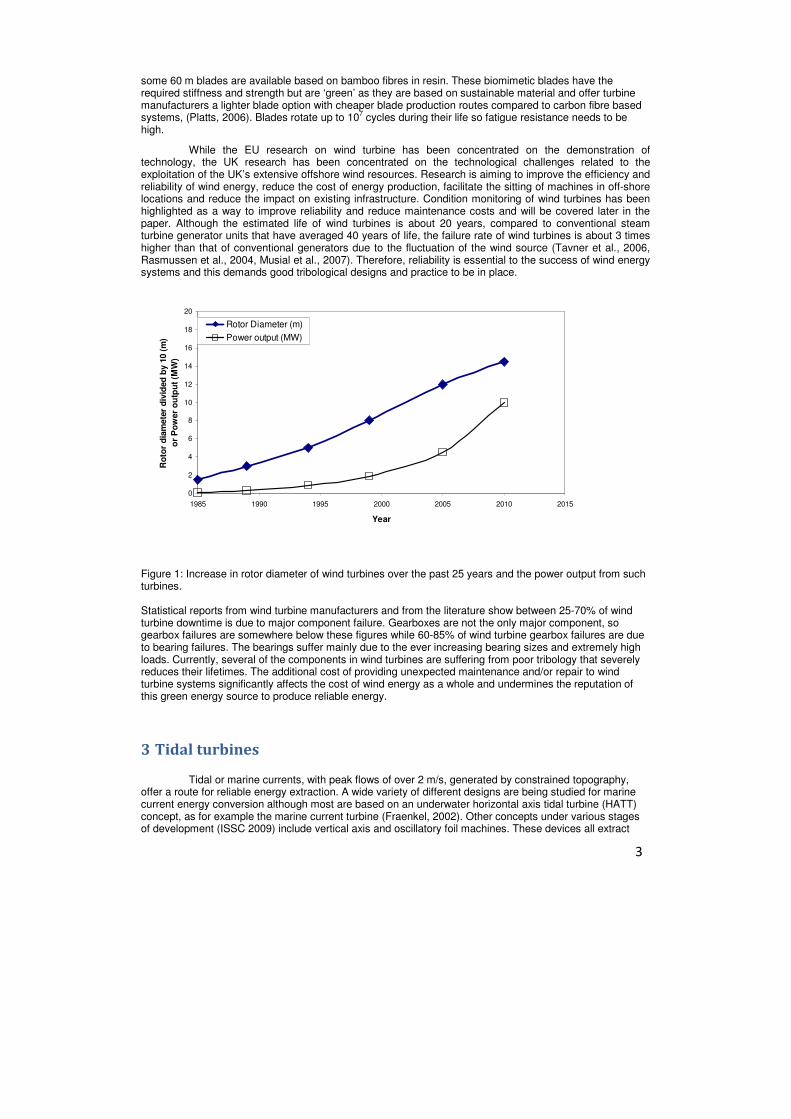
A recent study (DTI, 2007) examined the influence of design complexity on the cost-effectiveness
of HATT design. These included the use or otherwise of controllable pitch blades, variable RPM electrical generators, weather vane rotators and bi-directional blade designs. Figure 2 illustrates all design elements and environmental factors considered. A system analysis was used to develop a Fault Tree Analysis based reliability model for a farm of 30 x 1MW HATT with an operational farm life of 15 years. A Montecarlo simulation was used with assumed stochastic distributions for sub-system component reliability to examine the variation in energy capture and associated economic viability. The work demonstrated that the simpler system captures less energy, with an overall annual generator capacity factor of 23% for the fixed pitch system compared to 25% for the variable pitch. Importantly the fixed pitch system lowered the unit cost of energy by 10-20%. The only cases where this did not hold were when extreme reliability was assumed for the critical subsea systems. These are difficult to access and expensive to repair.
Wind Marine current
Velocity for max power (m/s) 12-13 2.5 Mass flow rate (tonnes/s) 30-40 900 Thrust (tonnes) 50 100 Rotor diameter (m) 52 20 Table 3: Comparison between wind and tidal 1MW machines.
Figure 2 Overall system diagram for generic 20m diameter, 1MW rated HATT designed to operate as a farm of 30 (DTI 2007).
4 Wave energy converters
The energy inherent in the orbital motion and pressure field beneath a wave presents a significant challenge to extract efficiently while being able to survive extreme storm conditions. Falnes (2007) reviewed

6
wave energy extraction methods, showing that the power flow intensity is up to five times larger for ocean waves than for the wind that generates the waves. Optimum wave interference, for a single oscillating system, occurs at the resonance (whereby the excitation force and the velocity of the device are in phase frequency) and for specific amplitude of the motions of the oscillator. In order to extract the maximum energy, the shape of the immersed volume has to be carefully designed and control strategies used to keep the phase between excitation and velocity close to zero for different wave periods.
In other design approaches, Leijon et al. (2006) and Agamloh et al. (2008) are working on electric converters directly driven by floaters experiencing oscillatory motions in waves. In the first case heave motion is linearly transmitted to the electrical converter; while in the second case translation motion is converted to a rotational motion through a ball screw. In other concepts, Valério et al. (2007) working on the Archimedes Wave Swing uses linear electrical converters driven by the motion of underwater floaters while Torresi et al. (2008), Thakker and Abdulhadi (2008) are researching air-flow turbines driven by Oscillating Water Columns. Chaplin et al. (2007) describe the ANACONDA concept based on a large water-filled rubber tube, aligned in the direction of wave propagation, in which the natural propagation speed of bulge waves is matched to the speed of the water waves to be captured. The bulge wave power is converted to electricity by a turbine. Model tests have shown that the capture width is up to four times the diameter of the tube.
The tribological components within such energy conversion machines are typically; hydraulic systems, pistons/cylinders, hinge bearings, sliding and rotating seals and embedded turbines. These must be compatible with the complex loadings and harsh marine environment of wave surface operation. In addition, access is limited to these components and therefore maintenance of them is difficult.
5 Environmental and loading conditions
The harshness of the maritime environment results in designs that have to be able to survive the extremes of loadings imposed by the wind and sea and yet be cost-effective in extracting a low energy density resource (Nielsen et al., 2009). The challenge of maintaining operational devices for 15+ years requires a clear understanding of their component material performance and associated environmental degradation. Offshore wind turbines require a suitable support structure and have been developed rapidly as they combine existing understanding from the oil and gas industry for their support structures alongside land based wind turbine technology. Tidal energy systems, and in particular those which exploit currents, are a relatively recent development. The system is mounted below the free surface and benefits from a predictable load regime dependent on the tidal phasing of the moon-earth-sun system. The system components are difficult (and expensive) to access with a resultant requirement for high reliability and low maintenance. The active components of wave energy systems are typically exposed to the full force of storm conditions at the free surface with extreme combinations of wind and wave. Designs often have to compromise efficient energy extraction for design for survival and is the reason why the development cycle for this class of device has been so long (40+ years). This paper will focus on Tribology of marine renewable energy systems and specifically on horizontal axis tidal and offshore wind turbines.
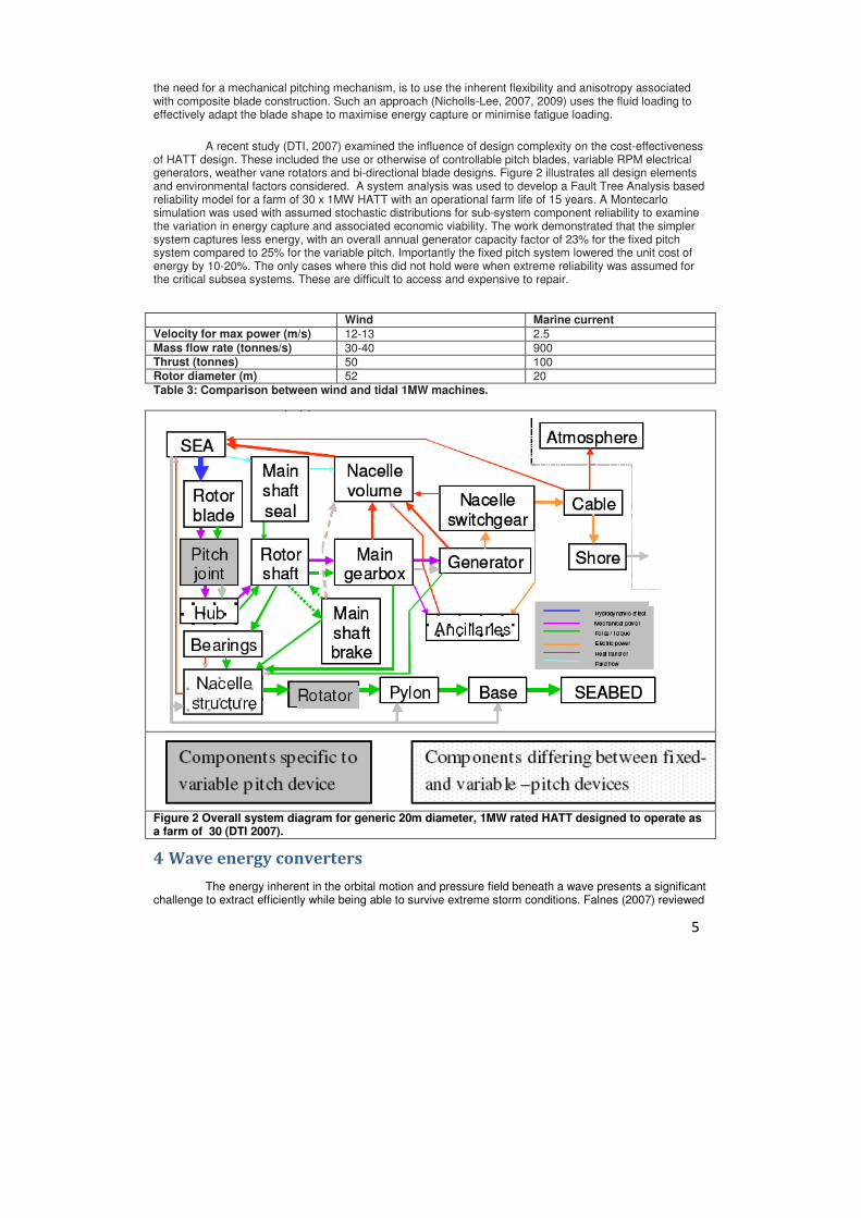
Due to spatial and temporal variation in the tidal speed the loadings on tidal machines and their tribological components are complex. This coupled with the large axial load/moments developed when extracting power requires these machines to be secured to seabed, either directly or via a moored floating structure. Figure 3 illustrates such possible structural concepts. The upstream bathymetry will control the turbulence levels and the velocity profile across the capture area of the machine. High currents give additional loadings on support structures and tribological components and the use of cylindrical support structures (lower manufacturing cost) will give rise to unsteady flows (vortex shedding) and associated vibrational response. Wave loadings will cause variations in flow seen by blades and again on subsea support structure. The scour regime can be severe and cause particulates to pass through the turbine rotor and could cause solid particle erosion damage of the blades or abrasive wear of bearing and/or seal surfaces.
7
Figure 3: Generic structural support systems for single HATT (adapted Nicholls Lee 2008)
Biofouling
The current issues restricting the development of tidal current turbines are material selection, loading conditions and environmental impacts. Surface and sub-marine structures have to withstand the aggressive marine environment with its corrosive salt water, fouling growth and abrasive suspended particles. Biofouling growth will effect wave machines more than submerged tidal systems. However, even at 5 m submerged depths the tidal systems and in particular the rotor hubs (low velocity parts) will be covered with fouling, (Apolinario and Coutinho, 2009). Several methods have been identified to prevent biofouling and corrosion, particularly around seals, welds, bearing surfaces and electrical insulation materials. Tidal turbines can typically generate 90% plus of energy from running for less than 60% of time. So is it best to stop the turbine and reduce mechanical wear/fatigue or to always rotate blades as this reduces risk of biofilm growth. It is not certain what speed of rotation is required to stop growth. Other methods to inhibit growth include antifouling paints and the use of sonic and ultra-sonic systems.
The structures and tribological components for marine turbines must also be designed to withstand transient forces caused by turbulence as well as by passing surface waves. The fluctuations in the velocity of the flow around a tidal current turbine rotor can lead to several severe problems, such as blade vibrations, which may lead to fatigue failure and/or bearing failure. When designing a tidal current turbine, turbulence levels must be taken into account to reduce its damaging effects. The use of computer software to model the water flow and prototype testing will play an important part in blade design and understanding tribological loads in bearings etc.
6 Tribological issues
As stated earlier in the paper there are several areas of concern for tribological components in
tidal and offshore wind turbines. These include solid particle (hail, sand etc) and cavitation erosion and foreign object damage of blades, tribocorrosion of blades and bearings, biofouling and ice build up on blades causing increased drag, unknown and unusual loadings on bearings and seals, extremely high torques through the drive train of gearboxes as well as lubricant degradation particularly from salt water contamination and atmospheric corrosion. All of these add uncertainty to the lifetime of tidal and wind turbines
Most turbines use a horizontal axis setup with three blades. The blades are connected to the main drive shaft inside the nacelle, where transmission continues to the gearbox and generator, Figure 4. A typical gearbox arrangement can be seen in Figure 5.

8
Figures 4 and 5. – Adapted from: Souichi Yagi, “Bearings for Wind Turbine”, NTN Technical Review No.71 (2004).
From the very first days of the wind turbine industry, high gearbox failure rates have been observed (McNiff et al. 1990). These were mainly due to poor design and under estimation of loads. As wind turbines increase in size, their operating conditions become ever more extreme. Since gearboxes are extremely expensive, their high failure rates are resulting in a higher cost for wind energy, exasperated by price escalation due to the uncertainty of gear box life expectancy. This latter point is due to wind turbine manufacturers adding large contingencies to sales prices to cover warranty risks. Operators also include contingency funds into project financing and projected income for possible future problems outside the warranty time (Musial et al. 2007).
Despite manufacturers keeping to international standards for wind turbine gearbox manufacture (ISO/IEC 81400-4:2005), and the ANSI/AGMA/AWEA 6006-A03 standard containing maintenance specifications based upon an expected gearbox failure lifetime of twenty years, this does not result in gearboxes reaching their designed life time. Thus, major servicing is usually required far in advance of desired life expectancy (Rasmussen et al. 2004, Tavner et al. 2006).
Bearing failure is the largest concern, as statistical reports from wind turbine manufacturers show that bearing failure contributes approximately 50-85% of the total gearbox failure of wind turbines, due to extremely high stresses and loading phenomena not fully understood as well as wear debris entrainment. Both high load and debris entrainment cause excess clearances in the bearings. Bearing manufacturers follow international bearing rating standards (ISO 281:2007), however each manufacturer uses proprietary design life assessments which can introduce large differences in actual calculated bearing life. Gearbox manufacturers rely on bearing manufacturers for the bearing life assessment and commercial sensitivities often make this a less than transparent process (Musial et al. 2007). In addition, the bearing manufacturers will probably not have information about of the complex loading conditions the gearbox experiences. This results in bearings that are unable to sustain the unpredictable loads beyond the bearing mounting location, such as housing deformations, or flow fluctuations. Research at Southampton is being conducted into rolling contact fatigue (RCF) in bearing steels, namely subsurface White Etching Cracking (WEC), which accounts for the majority of bearing failures. The influence of hydrogen (e.g. oil decomposition or water contamination) as a root cause/accelerator to WEC is being investigated by RCF tests on a twin roller machine. The effect of rapid loading and slip, with novel oils and steels, are being conducted as well as the early detection of such failure mechanisms.
In would appear the industry requires a common method for identifying the actual loads and use these for calculating bearing life and a greater level of collaboration should result in reduce bearing failure rates, resulting in increased gearbox reliability to reducing the cost of wind energy. Emergency stops will typically lead to large turbine loads, particularly when the stops occur at the same time as wind gusts. Modern offshore wind turbines pitch the blades during storm conditions to minimize the blade loads.
Tribological components and associated problems
Whereas gearboxes have a regulated temperature and most are oil lubricated, the main rotor, pitch, yaw and generator bearings are often grease-lubricated and operate in temperatures from -30 °C to
9
+100 °C. There are concerns across certain parts of the system with stray electrical currents leading to wear and micropitting of gears and bearings due to electro-corrosion mechanisms. Gearbox: The gearbox steps the speed up from the input-shaft (~20rpm) to the high-speed shaft (~1500+rpm). In Figure 4, the first stage can be seen as a planetary system, with three parallel stages following. The gearbox low-speed bearing is subjected to cyclic loads (though the input shaft due to the transient loading of the wind and height varying torque of the blades). The high-speed bearings which support both radial and thrust loads, are highly susceptible to failure (Bartz 2005), being subjected to braking loads (from the over-speed brake on the high-speed shaft) and grid coupling loads (from grid fluctuations through the generator on the high-speed shaft) (Burton et al. 2001). Yaw Drive: This adjusts the blades in the direction of the wind, where the movement is made at increments of a few degrees (Bartz 2005). A typical yaw system involves a rolling slewing bearing that uses a rack-and-pinion system to allow several motors to control the axial motion, (Terrell et al. 2009). The yaw bearings and their control system suffer from premature failure by wear. These bearings are extremely large and pose many manufacturing problems. Pitch Drive: To obtain the maximal power from the wind, the pitch of each blade can be adjusted by actuators, which are either hydraulic or electromagnetic. These are situated at the base of each blade. The blade pitch control bearings and the attendant control system also still experience premature failure by wear. This is due to their large sizes (typically Ø2m+) which are extremely difficult to manufacture with the appropriate tolerances and surface finishes seen in smaller bearings (Terrell et al. 2009). Filtration: The gearbox oil used to lubricate bearings & gears is part of a circulatory system contained on most turbines wholly within the nacelle, which regulates oil temperature and filtering of contaminates. Pressure loss across the filters can reduce contaminate removal efficiency, which can be exasperated by cold starts because of increased oil viscosity (Terrell et al. 2009).
Contamination and lubricant degradation
Variations in external operating temperature and contamination degrade the lubricant, which
cause tribological problems for the bearings and gears including corrosion. Solid particles (wear debris) and water entrainment (salt water for offshore installations) are both possible contamination sources and are major concerns for wind turbine gearboxes. Water contamination: Water contamination can be extremely degrading to the gearbox lubricant. Only a small amount of water (<500ppm) substantially shortens the service life of rolling element bearings (Fitch 2008). Failure modes include: Hydrogen-induced fractures, corrosion, oxidation, lubricant additive depletion, oil flow restrictions, aeration/foaming, impaired lubricant film strength, microbial contamination and water washing. A list of all the detrimental effects to gearbox lubricant from water contamination can be found in the ANSI standard. To minimise water contamination when manufacturing and shipping the wind turbine, the manufacturing environment must be dry and clean, with components sealed to the atmosphere during shipping. However, wind turbines can still be affected by water contamination during service (Kotzalas et al. 2008). Particulate contamination: Particle contaminates are extremely damaging if entrained between contacts and can be introduced into the system from the atmosphere or from generation in service. In bearings, particles entrained between contacting surfaces cause micropitting, and also surface cracks which can end in fatigue spalling. In gears, hard particles can wear away material through abrasion, which results in clearance loss and reduced efficiency of power transmission. Hard ductile (T15 & 52100) particles, such as those of gear teeth wear debris have been identified as the most likely to cause fatigue spalling, with hard rigid (Al2O3 & SiC) and hard friable (TiC) following (Errichello and Muller 2002).

10
Ro
ller
bearin
gs
Jo
urn
al
Bearin
gs
Gear
bo
x
Bla
des
seals
Hyd
rau
lic
syste
m
Oil/g
rease
lub
rican
t Microbial attack � �
Erosion (rain, cavitation, solid particles)
� �
Rolling contact fatigue � � Impact/delamination wear � � Stick-slip � Tribocorrosion � � Oxidation � �
Contamination � � � � �
Fouling (i.e. marine growth)
�
Abrasion � � Corrosion � � � � Table 4. Degradation mechanisms seen by various tribological components in offshore wind, wave and tidal energy conversion systems.
Cavitation and cavitation erosion
Cavitation occurs when the local static pressure reduces to that of the vapour pressure of the
surrounding fluid. It is well established that material erosion can occur when such cavitities collapse very near to a solid surface. This collapse is characterized in some cases by a jet which is formed at the side of the cavitation volume farthest from the surface and is directed toward the wall (Plesset and Chapman, 1970). In other cases, collapse is associated with transient cavitation vortices downstream of cavities (Karimi and Avellan, 1986). Also, the collapse energy of cavities in a cloud can be forced toward a surface (Mørch, 1981). A recent study by Berchiche, Grekula, and Bark (2003) suggests that the collapse of “glassy cavities” also has a focusing effect on the collapse energy.
The power that can be transmitted as ship propulsive thrust is limited by occurrence of cavitation
(Carlton 1994). Likewise, a rotating tidal turbine blade will experience cavitation if the local blade surface speed reaches a critical value for a given depth of immersion, made up of tidal current, rotational speed and flow acceleration due to the blade hydrofoil shape. The EROCAV project (Friesch 2003, 2004), from a study on a full and model scale propellers classifies seven different types of cavitation where erosion occurred: (1) fluctuating/travelling sheet cavitation, (2) cloudy tip vortex, (3) severe/unstable mid-chord cavitation developing into clouds, (4) vortices originating from the leading edge on the tip, ending cloudy, (5) foaming root cavitation, root vortex cavitation, ending cloudy, (6) foaming sheet close to trailing edge, and (7) sheet cavitation along the leading edge of the face side, breaking up into clouds. The relative severity of cavitation damage will depend on the details of the local flow. For tidal turbines which have relatively large diameters the high risk area is the blade tip as it approaches the top of its rotation. It is here that the local hydrostatic pressure is lowest and at the outer radius blade speed highest. While it is certain that cavitation that will degrade hydrodynamic performance of the blade it is not yet clear what an acceptable level of tip cavitation will be and how the tip shape influences the possible occurrence of cavitation damage. Typically, keeping the speed of rotation of the turbine as high as possible improves the hydrodynamic efficiency as well as reducing the size of the step-up of rotation speed needed in the gearbox. Thus, it is likely that turbine design will target a limited amount of cavitation. Use of materials such as stainless steel may be necessary near the blade tip as composite surfaces often have a low threshold for erosion, ITTC 2005.
Condition monitoring
Due to access difficulties, currently there is hardly any condition-based monitoring strategy in place for wind turbine gearboxes. Condition monitoring of Wind Turbines should therefore, detect gearbox problems before they lead to failure and give advanced warning for maintenance planning and reducing the amount of downtime. Also condition monitoring should give real-time monitoring of blade loads, imbalances, ice build-up, yaw misalignment and blade damage and thereby offer remote correction of eccentric loading to prevent

11
expensive asset damage New condition monitoring techniques can offer advanced diagnostics capabilities for early fault detection . Also a system could use remote sensing to acquire detailed information about the inflow across the entire rotor. The turbine response to this measured inflow can be used to inform the health of turbine. The condition monitoring techniques currently used or potentially could be used are discussed below:
As a renewable energy source, one of the concerns of using wind turbines is its high cost, especially the cost for operation and maintenance. It is estimated that these costs occupies 10-15% and 20-25% of the overall cost for onshore and off-shore wind turbines, where cost from unscheduled maintenance is about 30-60% of total (Lu & Li; Walford 2006). Compared to conventional steam turbines, the estimated life of wind turbines is significantly shorter mainly due to the much higher failure rate due to the fluctuation of wind source (Tavner et al. 2006, Rasmussen et al. 2004, Musial et al. 2007, Jensen 2009). Therefore, reliability and preventative maintenance are essential to the success of wind energy systems.
Condition-based maintenance for wind turbines is relatively new but is a fast developing research area.
Various on-line and off-line monitoring techniques, including vibration, temperature, debris and electrical monitoring, are being developed for wind turbine condition monitoring. However, adaptation of these techniques has been challenging and the effectiveness is thus greatly affected due to the rapidly varying load, slow-speed and non-rigid foundation in wind turbines. Hameed (2009, 2010) reviewed and evaluated condition monitoring techniques and algorithms that can be applied for wind turbines, looking into the applicability of sensing techniques and algorithms developed for other machinery for wind energy converters. Nine sensing techniques were identified to be suitable for either the entire wind turbine system or its critical components.
Although vibration monitoring has achieved significant success in detecting gearbox bearing failures at
high speed stage, it has been found challenging in detecting faults in slow-speed stage bearings (Christensen and Andersson 2009). Vestas is developing large-scale remote vibration condition monitoring network for wind turbines (Christensen and Andersson 2009). Accelerometers have been mounted on the drive train, generator and main bed frame and over hundred parameters on each turbine are monitored, including overall RMS, vibration at tooth mesh frequencies and shaft rotating speed, etc. Based on the analysis of these parameters the diagnostic experts are able to identify mechanical failures such as bearing, coupling, gear and supporting structure faults as well as misalignment and unbalance faults. To accommodate the widely varied operation conditions of wind turbines, active power bins and corresponding alarm limits are defined to enable meaningful comparison. However, the successful examples shown in this paper are all based on the overall RMS trend analysis, where alarms were effective after significant wear of the components had taken place. Although it was indicated that achievable lead time to maintenance and repairs prior to complete gearbox failures, earlier warnings should be sought should the severe wear of the components be prevented.
Lekou et al (2009) have implemented an acoustic emission system together with a conventional load
and wind flow and speed measuring system on a high speed shaft of a wind turbine and are investigating the feasibility of using AE for gearbox monitoring. Initial test data has been collected to establish the baseline AE measurements under normal operation of the wind turbine. It is expected to serve as the basis for trending analysis.
Development in wind turbine condition monitoring has also been focused on the blades, lubricants and
the generators. Ciang et al (2008) reviewed acoustic emission, thermal imaging, ultrasonic, fibre optics and other techniques that potentially suitable for wind turbine structural health monitoring. Yang et al has proposed a continuous wavelet transform based energy tracking method to analyse electric power signals that is to be applied to real wind turbines for generator monitoring (Yang & Tavner 2010). The use of on-line real time oil monitoring can also provide early indication of developing problems before wear occurs and to maximize oil life.
Although basic condition monitoring systems are offered by the wind turbine manufacturers, these
systems are still limited to general vibration-based condition monitoring. Advanced and robust condition monitoring systems that can predict and diagnose incipient component faults are under development by researchers, sensor and turbine manufacturers.
Tribocorrosion
Tribocorrosion issues are likely to be seen on the blades and bearings lubricated with water contaminated lubricants. The blades of tidal turbines could see turbulent slurry flows (silt, sediments and
12
sand containing flows) and/or cavitation interact with corrosion processes. These are sufficient to cause plastic deformation of the surface or puncture the corrosion resistant passive films on unprotected metallic surfaces and even can strip protective paints from metallic surfaces. These cases are where mechanical and electrochemical interactions are involved and can lead to significant acceleration of material loss and dramatically reduced lifetimes by a factor of ten.
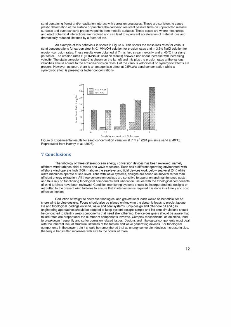
An example of this behaviour is shown in Figure 6. This shows the mass loss rates for various sand concentrations for carbon steel in 0.1MNaOH solution for erosion rates and in 3.5% NaCl solution for
erosion-corrosion rates. These results were obtained at 7 m/s fluid stream velocity and at 40°C in a slurry pot tester. The erosion rates E (0.1MNaOH solution results) shows a non-linear increase with increasing velocity. The static corrosion rate C is shown on the far left and this plus the erosion rates at the various velocities should equate to the erosion-corrosion rates T at the various velocities if no synergistic effects are present. However, as seen, there is an antagonistic effect at 0.5%w/w sand concentration while a synergistic effect is present for higher concentrations.
0 0.5 1 2 50
4
8
12
16
20
24
28
Mass Loss R
ate / m
g hr-1
Sand Concentration / % by mass
0.1M NaOH
3.5% NaCl
Figure 6. Experimental results for sand concentration variation at 7 m s
-1 (294 µm silica sand at 40°C).
Reproduced from Harvey et al. (2007).
7 Conclusions
The tribology of three different ocean energy conversion devices has been reviewed, namely offshore wind turbines, tidal turbines and wave machines. Each has a different operating environment with offshore wind operate high (100m) above the sea-level and tidal devices work below sea-level (5m) while wave machines operate at sea-level. Thus with wave systems, designs are based on survival rather than efficient energy extraction. All three conversion devices are sensitive to operation and maintenance costs and thus rely on functioning tribological components and lubrication. Issues with the tribological components of wind turbines have been reviewed. Condition monitoring systems should be incorporated into designs or retrofitted to the present wind turbines to ensure that if intervention is required it is done in a timely and cost effective fashion.
Reduction of weight to decrease tribological and gravitational loads would be beneficial for off-shore wind turbine designs. Focus should also be placed on knowing the dynamic loads to predict fatigue life and tribological loadings on wind, wave and tidal systems. Ship design and off-shore oil and gas engineering approaches should be adopted to keep system designs simple and life time simulations should be conducted to identify weak components that need strengthening. Device designers should be aware that failure rates are proportional the number of components involved. Complex mechanisms, as on ships, tend to breakdown frequently and suffer corrosion related issues. Designs and tribological components must deal with the inherent lack of structural stiffness of the turbine and wave generating devices. For tribological components in the power train it should be remembered that as energy conversion devices increase in size, the torque transmitted increases with size to the power of three.
13
References
Agamloh, E.B., Wallace, A.K. & von Jouanne, A. 2008 A novel direct-drive ocean wave energy extraction concept with
contact-less force transmission system. Renewable Energy. 33:3, pp. 520-529. Apolinario & Coutinho, 2009 Understanding the biofouling of offshore and deep-sea structures. In Advances in
marine antifouling coatings and technologies. chapter 6, pp. 132. Eds: Claire Hellio and Diego Yebra, Woodhead Publishing, Cambridge UK, 2009.
Bahaj, A.S. & Myers, L.E. 2003 Fundamentals Applicable to the Utilisation of Marine Current Turbines for Energy Production. Renewable Energy. vol. 28, Issue 14, pp. 2205-2211.
Bahaj, A.S. & Myers, L.E. 2004 Analytical Estimates of the Energy Yield Potential from the Alderney Race (Channel Islands) using Marine Current Energy Converters. Renewable Energy, vol. 29, Issue 12, pp. 1931-1945.
Bahaj, A.S., Chaplin, J.R., Molland, A.F., Batten, W.M.J., 2005. Experimental investigation into the hydrodynamic performance of marine current turbines. Sustainable Energy Series, Report No. 3, Southampton University.
Bahaj, A.S., Molland, A.F., Chaplin, J.R., Batten, W.M.J., 2007. Power and thrust measurements of marine current turbines under various hydrodynamic flow conditions in a cavitation tunnel and a towing tank. Renewable Energy 32 (3), 407–426.
Bahaj, A.S., Batten, W.M.J. & McCann, G. 2007 Experimental verifications of numerical predictions for the hydrodynamic performance of horizontal axis marine current turbines. Renewable Energy. vol. 32, Issue 15, pp. 2479-2490.
Bahaj A.S, Blunden L.S. and Anwar A.A, 2008, Formulation of the Tidal-current Energy Device Development and Evaluation Protocol. Sustainable Energy Series, Report 5, August 2008,
Baltazar, J. & Falçao de Campos, J.A.C. 2008 Hydrodynamic Analysis of a Horizontal Axis Marine Current Turbine With a Boundary Element Methods. Proceedings 27th International Conference on Offshore Mechanics and Arctic
Engineering (OMAE 2008), Estoril, Portugal, 15-20 June 2008. Bartz, W.J. 2005 Tribological aspects of wind power plants. Proceedings of the World Tribology Congress III,
Washington, D.C., USA, 2005. Batten, W.M.J., Bahaj, A.S., Molland, A.F. & Chaplin, J.R. 2007 Experimentally validated numerical method for the
hydrodynamic design of horizontal axis tidal turbines. Ocean Engineering. 34, pp. 1013–1020. Batten W.M.J., Bahaj A.S., Molland A.F. and Chaplin J.R., 2008 The Prediction of the Hydrodynamic Performance of
Marine Current Turbines, Renewable Energy, Volume 33, Issue 5, May 2008, pp 1085-1096. Berchiche, N., Gvekula, M. & Bark, G. 2003 Concept of Focusing of Collapse Energy – Application to Cavitation
Observations. CAV 2003, Osaka, Japan. Blunden, L.S. & Bahaj, A.S. 2007 Tidal Energy Resource Assessment for Tidal Stream Generators. Proceedings of the
Inst Mech.E Part A, J. Power and Energy, 221, pp. 130-146. Blunden, L.S., Batten, W.M.J. & Bahaj, A.S. 2008 Comparing energy yields from fixed and yawing horizontal axis
marine current turbines in the English channel. Proceedings 27th International Conference on Offshore
Mechanics and Arctic Engineering (OMAE 2008), Estoril, Portugal, 15-20 June 2008. Blunden, L.S. & Bahaj, A.S. 2008 Flow through large arrays of tidal energy converters: is there an analogy with depth
limited flow through vegetation? Proceedings World Renewable Energy Congress (WREC X), Glasgow, UK, 19-25 July 2008, pp. 1091-1096.
Burton, T., Sharpe, D., Jenkins, N., Bossanyi, E., Wind Energy Handbook, Wiley (Blackwell), 2001. Carlton, J.S., 1994. Marine Propellers and Propulsion. Butterworth- Heinemann Cantwell, B.J. 1981 Annu. Rev. Fluid Mech. 13, pp. 457–515. Carlton, J.S. 2007 Marine Propellers and Propulsion. Butterworth- Heinemann. Chaplin, J.R., Farley, F.J.M., Prentice, M.E., Rainey, R.C.T., Rimmer, S.J., 2007 Development of the Anaconda all-rubber
WEC. Proceedings of the 7th European Wave and Tidal Energy Conference, Porto, September 11-13, 2007. Christensen, J.J. & Andersson, C. 2009 Remote condition monitoring of Vestas turbines. Proceedings of EWEC 2009.
Technical Track – Operation and Maintenance, Marseille, France, March 16-19 2009. Ciang, C.C. 2008 Structural health monitoring for a wind turbine system: a review of damage detection methods.
Meas. Sci. Technol. 19, pp.1-20. Clarke, J., Connor, G., Grant, A., Johnstone, C. & Ordonez-Sanchez, S. 2008 Contra-rotating Marine Current Turbines:
Performance in Field Trials and Power Train Developments. Proceedings World Renewable Energy Congress
(WREC X), Glasgow, UK, 19-25 July 2008. DTI (2007). Economic viability of a simple tidal stream energy device, UK Department of Trade and Industry, Contract
No.TP/3/ERG/6/1/15527/REP. Errichello, R. & Muller, J. 2002 Oil cleanliness in wind turbine gearboxes. Machinery Lubrication.
14
Falnes, J. 2007 A review of wave-energy extraction. Marine Structures, 20:4, pp. 185-201. Fitch, J. 2008 How Water Causes Bearing Failure. Machinery Lubrication Magazine. Fraenkel, P.L. 2002 Power from marine turbines. Proceedings of the Institution of Mechanical Engineers Part A 216,
pp. 1–14. Fraenkel, P.L. 2004 Tidal turbines harness the power of the sea. Reinforced plastics, Elsevier, pp. 44-47. Friesch, J. 2003 Erosion Problems on Fast High Powered Ships. FAST 2003, Naples, Italy, October 7-10. Friesch, J., Kuiper, G., Briancon, L., Lee, D. & Wilczynski, L. 2004 Correlation Between Full Scale and Model Scale
Results on Propeller and Rudder Erosion. Proc. of Cavitation Erosion Workshop. Bassin d’Essais des Carenes, France.
Friesch, J. 2004 EROCAV-A Three Year EU Project Successfully Completed. HSVA, News Wave, January. Garrett, C. & Cummins, P. 2007 The efficiency of a turbine in a tidal channel. Journal of Fluid Mechanics, 588(-1), pp.
243-251. Harvey, T. J.; Wharton, J. A.; Wood, R. J. K. 2007 Tribology – Mater. Surf. Interfaces, 1(1), pp. 33–47. Hameed, Z. 2009 Condition monitoring and fault detection of wind turbines and related algorithms: A review.
Renewable & Sustainable Energy Reviews. 13(2009)1-39. Hameed, Z. 2010 Practical aspects of a condition monitoring system for a wind turbine with emphasis on its design,
system architecture, testing and installation. Renewable Energy. 35, pp. 879-894. Harvey, T. J.; Wharton, J. A.; Wood, R. J. K. 2007 Tribology – Mater. Surf. Interfaces 2007, 1(1), 33–47. ITTC, Report of specialist committee on cavitation erosion on propellers and appendages on high powered/high speed ships, Proceedings of 24th International Towing Tank Conference, Vol. 2, pp. 509-542. Edinburgh Karimi, A. & Avellan, F., 1986 Comparisons of Erosion Mechanisms in Different Types of Cavitation. WEAR. vol. 113, pp. 305-322. Kotzalas, M.N., Needelman, W.M., Lucas, D.R., LaVallee, G.L. 2008 Improving wind turbine gearbox life by minimizing
oil contamination and using debris resistant bearings. Proceedings of the AWEA Wind Power Conference, Houston.
Leijon, M., Danielsson, O., Eriksson, M., Thorburn, K., Bernhoff, H., Isberg, J., Sundberg, J., Ivanova, I., Sjöstedt, E. Ågren, O., Karlsson, K.E. & Wolfbrandt, A. 2006. An electrical approach to wave energy conversion. Renewable
Energy, 31:9, pp. 1309-1319. Lekou, D.J. & Mouzakis, F. 2009 Fused acoustic emission and vibration techniques for health monitoring of wind
turbine gearbox and bearings. Proceedings of EWEC 2009. Scientific Track – Operation and Maintenance, Marseille, France, March 16-19 2009.
Leybourne, M.T., Batten, W.M.J., Bahaj, A.S., O’Nians, J. & Minns, N. 2009 A Parametric Experimental Study of the 2D Performance of a Ducted Wave Energy Converter. Proceedings Eighth European Wave and Tidal Energy
Conference, Uppsala, Sweden, 7-10 September 2009, pp. 264-269. Lu, B. & Li, Y. A review of recent advances in wind turbine condition monitoring and fault diagnosis. IEEE xplore
download, http://ieeexplore.ieee.org/stamp/stamp.jsp?arnumber=05208325. Mackay, E.B.L., Bahaj, A.S., Challenor, P. 2010a Uncertainty in wave energy resource assessment Part 1: Historic Data.
Renewable Energy, 35:8 pp 1792-1808 Mackay E. B. L., Bahaj A. S., Challenor, P. 2010b Uncertainty in wave energy resource assessment Part 2: Variability
and Predictability. Renewable Energy, 35:8 pp 1809-1819 Mason-Jones, A., O’Doherty, T., O’Doherty, D.M., Evans, P.S. & Wooldridge, C.F. 2008 Characterisation of a HATT
using CFD and ADCP site data. Proceedings World Renewable Energy Congress (WREC X), Glasgow, UK, 19-25 July 2008.
McNiff, B., Musial, W.D. & Errichello, R. 1990 Variations in Gear Fatigue Life for Different Wind Turbine Braking Strategies. Solar Energy Research Institute, Golden, Colorado USA, 1990. Mørch, K.A. 1981 Cavity Cluster Dynamics and Cavitation Erosion. Proc. of the ASME Cavitation and Polyphase Flow Forum. Boulder, Colorado.
Molland, A.F., Bahaj, A.S., Chaplin, J.R. & Batten, W.M.J. 2004 Measurements and Predictions of Forces, Pressures and Cavitation on 2-D Sections suitable for Marine Current Turbine. Proc. Instn. Mech.Engr Part M. J. Engineering
for the Maritime Environment, 218 Part M, 127-38. Musial, W., Butterfield, S. & McNiff, B. 2007 Improving wind turbine gearbox reliability. The 2007 European Wind
Energy Conference, Milan, Italy, May 7-10. Myers, L.E. & Bahaj, A.S. 2005 Simulated Electrical Power Potential Harnessed by Marine Current Turbine Arrays in
the Alderney Race. Renewable Energy, 30(11), pp. 1713-1731. Myers L.E. and Bahaj A.S., 2006 Power Output Performance Characteristics of a Horizontal Axis Marine Current
Turbine, Renewable Energy, Volume 31, Issue 2, February 2006, pp 197-208. Myers, L.E. & Bahaj, A.S. 2008 Scale reproduction of the flow field for tidal energy converters. Proceedings World
Renewable Energy Congress (WREC X), Glasgow, UK, 19-25 July 2008.

15
Myers, L.E., Bahaj, A.S., Germain, G. & Giles, J. 2008 Flow boundary interaction effects for marine current energy conversion devices. Proceedings World Renewable Energy Congress (WREC X), Glasgow, UK, 19-25 July 2008, pp. 711-716.
Myers, L.E. & Bahaj, A.S. 2009 Near wake properties of horizontal axis marine current turbines. Proceedings Eighth
European Wave and Tidal Energy Conference, Uppsala, Sweden, 7-10 September 2009, pp 558-565. Nicholls-Lee, Rachel and Turnock, Stephen R. (2007) Enhancing performance of a horizontal axis tidal turbine using
adaptive blades. In, OCEANS 2007 - Europe. USA, Institute of Electrical and Electronics Engineers, 1-6. Nicholls-Lee, R.F and Turnock, S.R. (2008) Tidal energy extraction: renewable, sustainable and predictable. Science
Progress, 91, (1), 81-111. (doi:10.3184/003685008X285582) Nicholls-Lee, R.F., Boyd, S.W. and Turnock, S.R. (2009) Development of high performance composite bend-twist
coupled blades for a horizontal axis tidal turbine. In, 17th International Conference on Composite Materials, Edinburgh, UK 27 - 31 Jul 2009. London, UK, Institute of Materials, Minerals and Mining, 10pp.
Nielsen, F.G., Argyriadis, K., Fonseca, N., Le Boulluec, M., Liu, P., Suzuki, H., Sirkar, J., Tarp-Johansen, N.J., Turnock, S.R., Waegter, J. & Zong, Z. 2009 [Report of] Specialist Committee V.4: ocean, wind and wave energy utilization. In Proceedings of the 17th International Ship and Offshore Structures Congress. Seoul, Korea, Seoul National University, pp. 201-257.
Panton, R.L. 1984 Incompressible Flows. Wiley/Interscience: New York,. pp. 71. Platts, M.J. 2006 Wind energy turns to bamboo. Energy Materials, 1, (2), pp. 84-87. Plesset, M.S. & Chapman, R.B. 1970 Collapse of Initially Spherical Vapour Cavity in the Neighbourhood of Solid
Boundary. Journal of Fluid Mechanics. vol. 47, Part 2, pp. 283-290. Rasmussen, F., Thomsen, K. & Larsen, T.J. 2004 The gearbox problem revised. Riso Fact Sheet AED-RB-17(en), Riso
National Laboratory, Roskilde, DK. Robinson, S.Jensen, O.L. 2009 Wind turbine gearbox bearings – failure and problems. Presentation by Mr Jensen,
Vestas Wind Systems A/S Technology R&D, Drive Train, Feb 2009. (Unpublished.) Rourke, F.O., Boyle, F., Reynolds, A. Tidal energy update 2009 , Applied Energy 87 (2010) 398–409 Thakker, A. & Abdulhadi, R. 2008 The performance of Wells turbine under bi-directional airflow. Renewable Energy,
33:11, pp. 2467-2474. Tavner, P.J., Xiang, J. & Spinato, F. 2006 Reliability analysis for wind turbines, Wind Energy Journal, 10(1), John Wiley
and Sons., PAGE? Terrell, E.J., Needelman, W.M. & Kyle, J.P. 2009 Tribological Challenges to the System. Proceedings of the STLE/ASME
International Joint Tribology Conference. Torresi, M., Camporeale, S.M., Strippoli, P.D. & Pascazio, G. 2008 Accurate numerical simulation of a high solidity
Wells turbine. Renewable Energy, 33: 4, pp. 735-747. Valério, D., Beirão, P. & Sá da Costa, J. 2007 Optimisation of wave energy extraction with the Archimedes Wave
Swing. Ocean Engineering, 34:17-18, pp. 2330-2344. Walford, C.A. 2006 Wind turbine reliability: understanding and minimizing wind turbine operation and maintenance
costs. Scandia Report, SAND 2006-1100, Sandia National Laboratories. Yang, W. & Tavner, P.J. 2010 Cost-effective condition monitoring for wind turbines. IEEE Transactions on Industrial
Electronics. 57 (1), pp. 263-271.