trimble dini quick-start guide - csds inc. · trimble ® dini ® quick-start guide ... instrument...
TRANSCRIPT

© Copyright 2000-2010 California Surveying & Drafting Supply. Not to be copied or distributed without permission. 1
Trimble® DiNi® Quick-Start Guide California Surveying & Drafting Supply Technical Support Services
Revision 1

© Copyright 2000-2010 California Surveying & Drafting Supply. Not to be copied or distributed without permission. 2

© Copyright 2000-2010 California Surveying & Drafting Supply. Not to be copied or distributed without permission. 3
Contents: DiNi Setup & Configuration…………………………………………… 4 DiNi Commands, Keys & Configuration…………………………… 5 Configuring the DiNi…………………………………………………… 6 Creating a new project………………………………………………… 7 Completing a line (level run)………………………………………… 8 Data Transfer/Downloading & Processing……………………… 9 Additional Features and Functions………………………………… 15 Support Contacts………………………………………………………… 16

© Copyright 2000-2010 California Surveying & Drafting Supply. Not to be copied or distributed without permission. 4
DiNi Setup & Configuration: An instrument setup with good measuring stability will increase the precision in the measurement result and allow you to utilize the precision of the Trimble DiNi to its full extent. As pictured in the diagram below, tripod leg spacing of at least 1-meter (approximately 3-ft) is ideal.
Ensure that your tripod & tribrachs are fully adjusted and all screws are tightened in order to avoid any play. Trimble also highly recommends using survey-quality tripods with heads made of steel (i.e. the Crain Trimax Tripod) – fiberglass or other composite mounting planes are not recommended. Temperature: Take into consideration that a level requires sufficient time to adjust to the ambient temperature. The following rule-of-thumb for a high-precision measurement applies: Temperature difference in degrees Fahrenheit x 1= duration of minutes required for the instrument to adjust to the new temperature. Avoid sighting across fields with intense heat refraction by sunlight (i.e. on a summer afternoon).

© Copyright 2000-2010 California Surveying & Drafting Supply. Not to be copied or distributed without permission. 5
DiNi Commands, Keys & Configuration (Initial Setup, Units, Etc.): DiNi keys/physical buttons:
On/Off Key.
Instrument Power Key
Trigger Key.
Takes a measurement.
Trigger Key (Right-Hand Side).
Takes a measurement.
Toggle or “Spider” Key.
Navigates through menus, shows drop-down lists and changes check-box status.
Enter Key.
Enter/Return Key.
Escape Key.
Returns to Previous screen/menu/main menu.
Alpha Key.
Switches keyboard keys to Alpha or Numeric functions.
Trimble Key.
Displays the Trimble Functions menu.
Backspace Key.
Deletes previous input.
© Copyright 2000-2010 California Surveying & Drafting Supply. Not to be copied or distributed without permission. 6
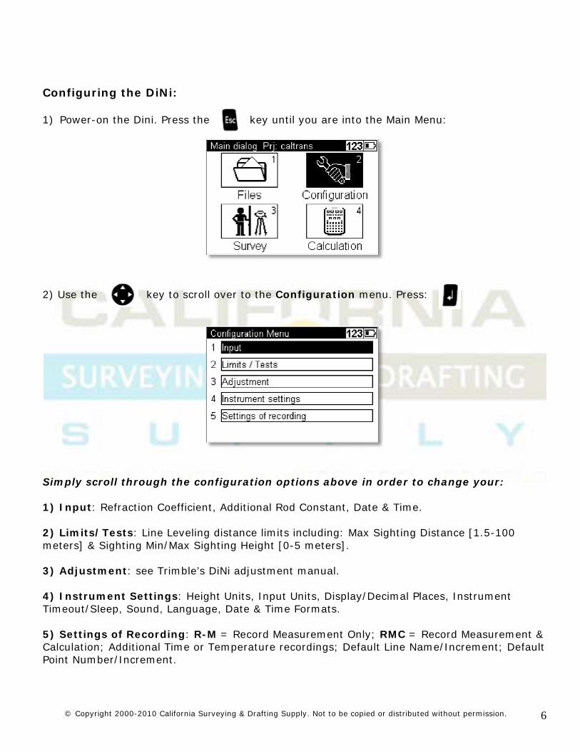
Configuring the DiNi: 1) Power-on the Dini. Press the key until you are into the Main Menu:
2) Use the key to scroll over to the Configuration menu. Press:
Simply scroll through the configuration options above in order to change your: 1) Input: Refraction Coefficient, Additional Rod Constant, Date & Time. 2) Limits/Tests: Line Leveling distance limits including: Max Sighting Distance [1.5-100 meters] & Sighting Min/Max Sighting Height [0-5 meters]. 3) Adjustment: see Trimble’s DiNi adjustment manual. 4) Instrument Settings: Height Units, Input Units, Display/Decimal Places, Instrument Timeout/Sleep, Sound, Language, Date & Time Formats. 5) Settings of Recording: R-M = Record Measurement Only; RMC = Record Measurement & Calculation; Additional Time or Temperature recordings; Default Line Name/Increment; Default Point Number/Increment.

© Copyright 2000-2010 California Surveying & Drafting Supply. Not to be copied or distributed without permission. 7
Creating a new project & completing a line (level run):
1) Press the key until you are back into the main menu, toggle to Files and press Enter :
2) From the Files menu, select Project menu and press Enter > New Project > Input the Project details (Name, Operator, Notes), then Enter to create/store :

© Copyright 2000-2010 California Surveying & Drafting Supply. Not to be copied or distributed without permission. 8
Creating & Completing a Line (Level Run):
Once your job has been created, press the Escape key until you are back into the main menu. To create a new line, toggle to the Survey menu and press Enter. From the Survey menu, scroll to Line leveling and press Enter:
You may either start a new line (run), or resume from an
existing line (run). If you choose Alternate (checking the box by pressing “left” on the toggle key) – you will alternate your
observations – for example, a BFFB workflow will automatically switch to FBBF as you progress along the line.
Enter your line leveling benchmark point. Press Enter/Cont.
to store this BM point.
You are now ready to observe the Backsight/Benchmark! Aim the DiNi to the BS Barcode Rod and press the trigger button.
You have now made your first backsight observation on the BM elevation that you had keyed in. The diagram above shows that the BFFB with a checkmark means that your backsight has been
observed – the BFFB means that the next observation to be made is the Foresight. Press the trigger button to shoot the
foresight.

© Copyright 2000-2010 California Surveying & Drafting Supply. Not to be copied or distributed without permission. 9
Once you have completed your Line (run)/setup, you may
either traverse forward/proceed to the next setup and continue taking observations, or you may end the line/run by toggling to
the Lend (Line End) softkey (key on the display screen).
You may enter a closing benchmark in order to view the calculated/observer height difference vs. the keyed-in
differences (or not, if you are performing additional runs/an open run).
Results with a closing BM Elevation entered.
Results without a closing BM Elevation entered.
Data Transfer/Downloading & Processing: Downloading & data from the DiNi level can be a quick and easy process. We recommend only using Trimble Business Center software version 2.20 or greater in order to download and process your DiNi Digital Level data. An excellent web-based tutorial is also available through the Trimble Knowledge Network, located at: http://www.trimble.com/tkn/
Import DiNi Digital Level Files (.dat)
DiNi digital level .dat (M5) files contain level data recorded in the field using a Trimble DiNi Digital level. In the device pane (the F10 key in Trimble Business Center), simply create a new device: Trimble DiNi with a USB connection. You may simply download your data directly from the DiNi, or if you have downloaded data to a different directory you may:
To import DiNi Digital level .dat files:
1. Do one of the following: o Click the icon on the toolbar.
o Select File > Import.

© Copyright 2000-2010 California Surveying & Drafting Supply. Not to be copied or distributed without permission. 10
The Import command pane displays.
2. Do one of the following:
o Select a folder in the Import Folder list.
o Click the icon to browse for a folder.
The default is the folder that you last imported from. The files contained in the selected folder appear in the Select File(s) area. The file names and file types are listed.
3. Select the DiNi digital level .dat file(s) you want to import.
1. In the Settings section at the bottom of the Import command pane, change the Automatically Numbered Points properties if necessary.
These properties help the software identify which points were auto-numbered by the DiNi level and which point IDs were entered by the user. Auto-numbered points typically are not points of interest and should not be created as points in the project.
o Starting Point - Specifies the first point ID number of the range of point ID numbers in the file you want to specify as automatically numbered points that should not be created in the project.
o Maximum Points - Specifies the maximum number of points in the file you want to be included in the range.
o Increment - Specifies the increment to be used when identifying point numbers in the range.
o Ending Point - Specifies the calculated ending point for the point range based on the other specified properties.
2. When you are done, click Import. The Level Editor dialog displays. In this dialog, you can see which level points were entered by the user (points of interest) and will be created in the project, and which points were automatically numbered by the DiNi and will not be created in the project. If necessary, you can make changes by checking or unchecking any point to include or not include it in the project.
View and Edit Level Data
The Level Editor dialog is displayed automatically immediately after you import level data. You can also display it any time after import by right-clicking the level data file in the Project Explorer pane and selecting Level Editor from the context menu. The Level Editor dialog enables you to do the following:

© Copyright 2000-2010 California Surveying & Drafting Supply. Not to be copied or distributed without permission. 11
• View all level readings from the field, and select any reading to be "enabled" (used for computation of level adjustment) or "disabled" (not used for computation of level adjustment).
• Select which points to import.
• Select to use raw or adjusted elevations in the project.
• View the sums of backsight distances and foresight distances.
• View the total misclosure and individual residuals for benchmarks and coordinates.
• View the elevation type for each point (benchmark, computed, or coordinate), including the start and end points, and change the elevation type as necessary.
• Manually enter benchmark heights and qualities.
• Assign an elevation coordinate already in the project that specifies height and quality that cannot be changed.
• Adjust level runs to spread any misclosure proportionately throughout all the measurements
• Merge level runs.
• Specify whether or not to allow a network adjustment to the level data after import (that is, specify whether level data is imported as observations or coordinates).
Before you get started:
Import level data into the project as described above.
To get started:
1. When you import a level data file, the Level Editor dialog automatically displays. Otherwise, you can display it at any time by doing either of the following:
o Right-click the imported level data file in the Project Explorer and select Level Editor from the context menu.
o Click Survey > Level Editor and select the imported level data file in the Select Leveling Files dialog.
The Level Editor dialog displays a tab for each level run in the data file, allowing you to view and/or edit each run individually.
2. If more than one Run tab is displayed, select the tab whose run you want to view or edit.
At the top of the tab, you can view the sum of backsight distances and foresight distances and the total misclosure to identify issues that might require corrective action.

© Copyright 2000-2010 California Surveying & Drafting Supply. Not to be copied or distributed without permission. 12
To select options:
1. At the top of the tab, select one of the following options:
o Select Use Adjusted Elevations to use elevations in the project that have been adjusted for misclosure. When you select this option, the Correction column is displayed in the table instead of the Misclosure column. The Correction column shows the correction used for the computation of the elevation for each point based on the misclosure value associated with that point.
o Select Use Raw Elevations to use elevations that have not been adjusted. When you select this option, the Misclosure column is displayed in the table instead of the Correction column. The Misclosure column shows the misclosure value for each benchmark or coordinate in the run.
2. If necessary, change the name of the run in the Run Name box.
3. In the Columns box in the lower left section of the dialog, select the columns you want to display in the table.
4. In the Creation Options box in the lower section of the dialog, select one of the following options:
o Allow Network Adjustment – Select this option if you want all elevations of interest imported as delta elevations and, therefore, adjusted as part of a network adjustment.
o Prevent Further Adjustment – Select this option if you want all elevations of interest imported as control coordinates and, therefore, not adjusted as part of a network adjustment.
To work with data in the table:
Each station point in the run is displayed in a table, along with the following information about the point (assuming all Columns boxes are checked in the lower left are of the dialog):
• The point ID
• Backsight, foresight, and/or intermediate rod readings associated with the point
• The change in elevation for the point based on the rod reading
• The raw elevation of the point based on the rod reading
• If the Use Adjusted Elevation box is checked, the correction required for the computation of the elevation for the point based on the associated misclosure value
• If the Use Raw Elevations box is checked, the misclosure value for each benchmark or coordinate in the run

© Copyright 2000-2010 California Surveying & Drafting Supply. Not to be copied or distributed without permission. 13
• The adjusted elevation
• The type of elevation used for the point: benchmark, coordinate, or computed
• The distance from the instrument to the level rod for each reading
• If applicable, a description entered for a reading associated with the point •
1. Ensure the boxes in the Create column are checked appropriately.
o Points you want imported into the project (for example, control points) should be checked.
o Points you do not want imported into the project (for example, turning points) should not be checked.
2. If necessary, edit any point IDs in the Point ID column.
If the icon displays following a point ID, the point ID is common to multiple runs. This can occur when the surveyor intentionally references the same point in multiple runs, in which case, no correction is required. It can also occur unintentionally when point IDs are automatically assigned in the level device for each run. In this case, you might need to rename one or more of the duplicate point IDs with unique point IDs, as necessary.
3. Ensure the enable/disable boxes in the BS (backsight), IS (intermediate), and FS (foresight) columns are checked appropriately.
o Readings you want included in the computation of a level adjustment should be checked (enabled).
o Readings you do not want included in the computation of a level adjustment should not be checked (disabled).
Note: Readings that were aborted in the field are imported as disabled (not checked). Note: For each point, there must always be at least one backsight reading and one foresight or intermediate reading. Therefore, you can disable a reading for a point only if the point includes additional readings of the same observation type. For example, if a point includes two backsight readings, you can disable one of them, but not both.
4. If necessary, in the Elevation Type column change the type of elevation used for any point:
o Benchmark – Select this option to specify that the elevation for the point be a manually entered benchmark elevation. Any point in the run can be designated as a benchmark.
o Coordinate – Select this option to specify that the elevation for the point be a coordinate already assigned to the point in the project. A coordinate can be assigned to a point only if there is a corresponding point already in the project with a coordinate elevation.

© Copyright 2000-2010 California Surveying & Drafting Supply. Not to be copied or distributed without permission. 14
o Computed – Select this option to specify that the elevation for the point be computed based on rod readings, benchmark and coordinate elevations entered for the run, and any adjustments performed on the run.
5. If necessary, for any points assigned a Benchmark elevation type, do the following:
1. Enter or change the value in the Elevation Type column.
2. Click the Quality icon and select the appropriate quality option.
If necessary, enter or change any descriptions in the Description column.
To adjust one or more of the level runs contained in the import file:
When a level run is adjusted, any misclosures are distributed proportionately throughout all the measurements in the run.
Note: When multiple intermediate (IS) observations exist for the same point ID in a level run, the software includes the intermediate readings in the level adjustment (the IS boxes will be checked in the Level Editor dialog), just as it is done during a network adjustment. If you do not want these intermediate readings to be included in the level adjustment, either uncheck the IS boxes or rename the associated point IDs so they are not the same.
1. Click Adjust Runs. The Adjust Runs dialog displays.
2. In the Adjust Runs dialog, select the runs you want to adjust.
These runs will all be adjusted simultaneously as one network. When runs have points in common, the recommended procedure is to adjust them together.
3. Click OK.
To merge level runs contained in the import file:
You can merge two level runs into one run if the last point ID in the first run selected for the merge matches the first point ID in the second run selected for the merge. For example, if the first run selected ends on point "1", the second run selected must start on point "1". This is helpful if two or more level runs were accidentally specified in the field for what should have been a single run (for example, one of the runs does not include a benchmark point). If necessary, you can merge another existing run with the newly created merged run using the same guidelines, and repeat as necessary.
1. Click Merge Runs. The Merge Runs dialog displays.
2. In the New Run Name box, enter the name for the new run.
You can enter the name of one of the runs you are merging, or you can enter a new name.
3. In the Start With list, select the run whose observations you want to use for the first part of the new run.

© Copyright 2000-2010 California Surveying & Drafting Supply. Not to be copied or distributed without permission. 15
4. In the Add This list, select the run whose observations you want to use for the second part of the new run.
5. Click OK. The Merge Runs dialog closes and the newly created run tab replaces the two merged run tabs in the Level Editor dialog.
If necessary, you can now merge another existing run with the newly created merged run using the same guidelines and instructions.
To complete viewing and editing:
1. Repeat the preceding procedures as appropriate for each run you want to view and/or edit.
2. When you are done working in the Level Editor dialog, click OK.
If the Level Editor dialog was displayed as part of a data file import, the import process completes and an Import Summary report displays, showing details of the import. Be sure to review any messages, warnings, or errors contained in the report to determine if any corrective action is required.
Additional Features and Functions of the DiNi level:
Once the preceded configurations and Line leveling (runs) are understood, the additional features and functions that can be performed with the DiNi level should be fairly straight-forward and intuitive enough to explore. For more details about these functions, please refer to Trimble’s DiNi User Guide v2.0 which is available for download at:
http://www.csdsinc.com/images/stories/caltrans/dini_user_guide_v200.pdf

© Copyright 2000-2010 California Surveying & Drafting Supply. Not to be copied or distributed without permission. 16
Support Contacts:
CSDS Support Representative: Phone Number:
Tom Cardenas – Northern California (Incl. Sonoma) (916) 806-2860
Mike Woodel – Sacramento & Nevada (916) 847-8351
Frank Frazer – Bay Area (Coastal) (925) 998-1161
Ben Scholes – Bay Area (SF & Inland) (510) 909-7695
Chris Bardon – Central Valley & Southern California (559) 708-8593
Matt Johnson – Support Assistant (916) 344-0232
Trimble Direct Support (800) 767-4822 Microsoft ActiveSync: http://www.microsoft.com Search: ActiveSync 4.5 Trimble Data Transfer Utility: http://www.trimble.com/datatransfer.shtml CSDS Online: http://www.csdsinc.com CSDS VSN Info: http://www.csvsn.com