tripping curves technical information - schneider-electric.com · on the load inrush current....
TRANSCRIPT
2
Complementary technical information
Tripping curves
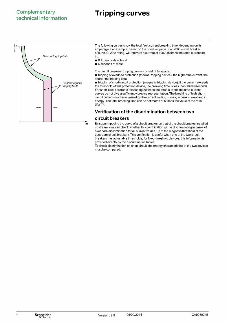
In
t
Thermal tripping limits
Electromagnetic tripping limits
min. max.
The following curves show the total fault current breaking time, depending on its amperage. For example: based on the curve on page 3, an iC60 circuit breaker of curve C, 20 A rating, will interrupt a current of 100 A (5 times the rated current In) in:
b 0.45 seconds at least b 6 seconds at most.
The circuit breakers’ tripping curves consist of two parts: b tripping of overload protection (thermal tripping device): the higher the current, the
shorter the tripping time b tripping of short-circuit protection (magnetic tripping device): if the current exceeds
the threshold of this protection device, the breaking time is less than 10 milliseconds.For short-circuit currents exceeding 20 times the rated current, the time-current curves do not give a sufficiently precise representation. The breaking of high short-circuit currents is characterized by the current limiting curves, in peak current and in energy. The total breaking time can be estimated at 5 times the value of the ratio (I2t)/(Î)2.
Verification of the discrimination between two circuit breakers By superimposing the curve of a circuit breaker on that of the circuit breaker installed upstream, one can check whether this combination will be discriminating in cases of overload (discrimination for all current values, up to the magnetic threshold of the upstream circuit breaker). This verification is useful when one of the two circuit breakers has adjustable thresholds; for fixed-threshold devices, this information is provided directly by the discrimination tables.To check discrimination on short circuit, the energy characteristics of the two devices must be compared.
Version : 2.9 05/09/2014 CA908024E
DB
1241
79

3
Complementary technical information
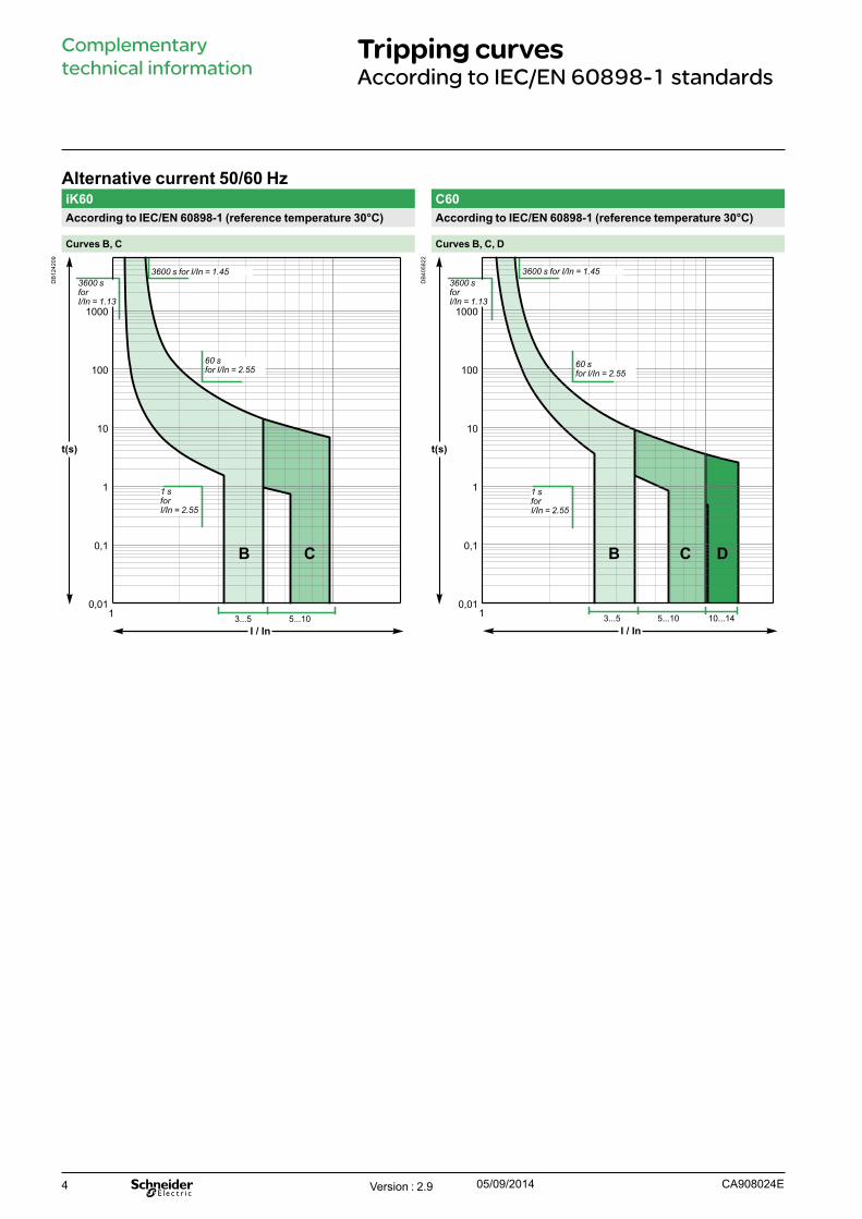
Tripping curvesAccording to IEC/EN 60898-1 standards
Alternative current 50/60 HziC60a/N/H/LAccording to IEC/EN 60898-1 (reference temperature 30°C)
Curves B, C, D rating up to 4 A Curves B, C, D rating 6 A to 63 A
DB
1241
80
t(s)
I / In
0,01
0,1
1
10
100
1000
1 3...5 5...10 10...14
C DB
DB
1241
85
t(s)
0,01
0,1
1
10
100
1000
I / In1
C DB
3...5 5...10 10...14
C120N/H DPN, DPN N, DPN H (circuit-breaker and residual current device)According to IEC/EN 60898-1 (reference temperature 30°C) According to IEC/EN 60898-1 (reference temperature 30°C)
Curves B, C, D Curves B, C, D
DB
1242
07
t(s)
I / In
0,01
0,1
1
10
100
1000
1
C DB
3...5 5...10 10...14
DB
1242
08
t(s)
I / In
0,01
0,1
1
10
100
1000
1
C DB
3...5 5...10 10...14
3600 s for I/In = 1.453600 sforI/In = 1.13
60 s for I/In = 2.55
1 s for I/In = 2.55
3600 s for I/In = 1.453600 sforI/In = 1.13
60 s for I/In = 2.55
1 s for I/In = 2.55
3600 s for I/In = 1.453600 sforI/In = 1.13
60 s for I/In = 2.55
1 s for I/In = 2.55
3600 s for I/In = 1.453600 sforI/In = 1.13
60 s for I/In = 2.55
1 s for I/In = 2.55
Version : 2.9 05/09/2014CA908024E
4
Complementary technical information
Tripping curvesAccording to IEC/EN 60898-1 standards
Alternative current 50/60 HziK60 C60According to IEC/EN 60898-1 (reference temperature 30°C) According to IEC/EN 60898-1 (reference temperature 30°C)
Curves B, C Curves B, C, D
DB
1242
09
t(s)
I / In
0,01
0,1
1
10
100
1000
1 3...5 5...10
CB
DB
4058
22
t(s)
0,01
0,1
1
10
100
1000
I / In
1 3...5 5...10 10...14
C DB
3600 s for I/In = 1.453600 sforI/In = 1.13
60 s for I/In = 2.55
1 s for I/In = 2.55
3600 s for I/In = 1.453600 sforI/In = 1.13
60 s for I/In = 2.55
1 s for I/In = 2.55
Version : 2.9 05/09/2014 CA908024E
5
Complementary technical information
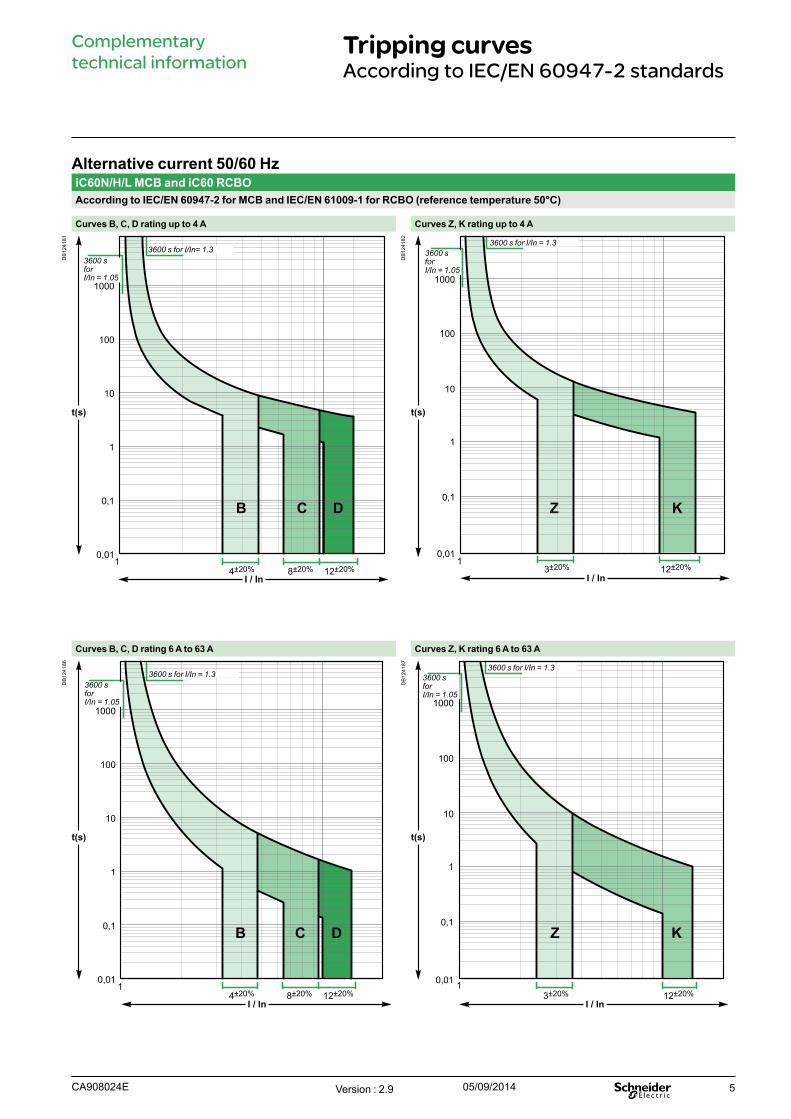
Tripping curvesAccording to IEC/EN 60947-2 standards
Alternative current 50/60 HziC60N/H/L MCB and iC60 RCBOAccording to IEC/EN 60947-2 for MCB and IEC/EN 61009-1 for RCBO (reference temperature 50°C)
Curves B, C, D rating up to 4 A Curves Z, K rating up to 4 A
DB
1241
81
t(s)
I / In
0,01
0,1
1
10
100
1000
14±20% 8±20% 12±20%
C DB
DB
1241
82
I / In
t(s)
0,01
0,1
1
10
100
1000
KZ
13±20% 12±20%
Curves B, C, D rating 6 A to 63 A Curves Z, K rating 6 A to 63 A
DB
1241
86
t(s)
0,01
0,1
1
10
100
1000
I / In
1
DB C
4±20% 8±20% 12±20%
DB
1241
87
I / In
1
t(s)
0,01
0,1
1
10
100
1000
KZ
3±20% 12±20%
3600 s for I/In= 1.3 3600 s for I/In = 1.3
3600 s for I/In = 1.33600 s for I/In = 1.3
3600 sforI/In = 1.05
3600 sforI/In = 1.05
3600 sforI/In = 1.05
3600 sforI/In = 1.05
Version : 2.9 05/09/2014CA908024E

6
Complementary technical information
Tripping curvesAccording to IEC/EN 60947-2 standards
Alternative current 50/60 HzReflex iC60N/H NG125a/N/H/LAccording to IEC/EN 60947-2 (reference temperature 50°C) According to IEC/EN 60947-2 (reference temperature 40°C)
Curves B, C, D Curves B, C, D
DB
1242
10
t(s)
I / In
0,01
0,1
1
10
100
1000
1
C DB
4±20% 8±20% 12±20%
DB
1242
11
t(s)
I / In
0,01
0,1
1
10
100
1000
1
C DB
4±20% 8±20% 12±20%
C60According to IEC/EN 60947-2 (reference temperature 50°C)
Curves B, C, D
DB
4058
23
t(s)
0,01
0,1
1
10
100
1000
C DB
I / In1
4±20% 8.5±20%12±20%
3600 s for I/In= 1.3 3600 s for I/In = 1.33600 sforI/In = 1.05
3600 sforI/In = 1.05
3600 s for I/In= 1.3 3600 sforI/In = 1.05
Version : 2.9 05/09/2014 CA908024E
7
Complementary technical information
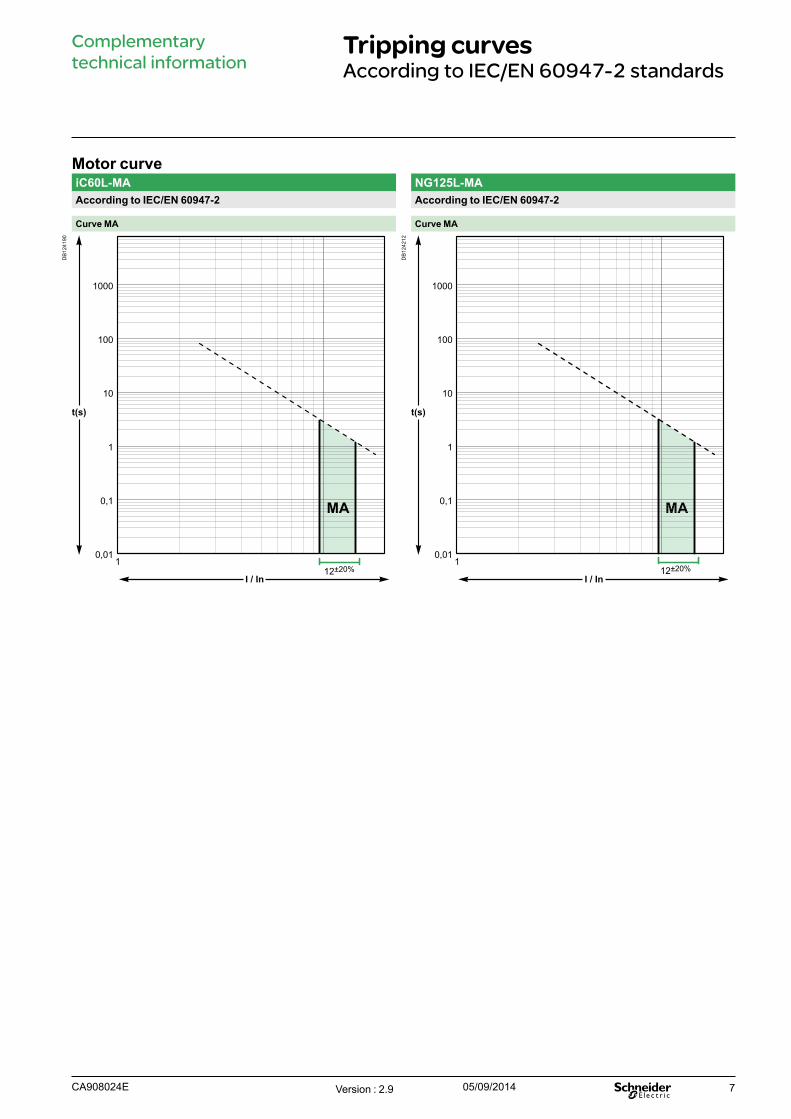
Tripping curvesAccording to IEC/EN 60947-2 standards
Motor curveiC60L-MA NG125L-MAAccording to IEC/EN 60947-2 According to IEC/EN 60947-2
Curve MA Curve MA
DB
1241
90
t(s)
0,01
0,1
1
10
100
1000
I / In
1
MA
12±20%
DB
1242
12
t(s)
0,01
0,1
1
10
100
1000
I / In
1
MA
12±20%
Version : 2.9 05/09/2014CA908024E
8
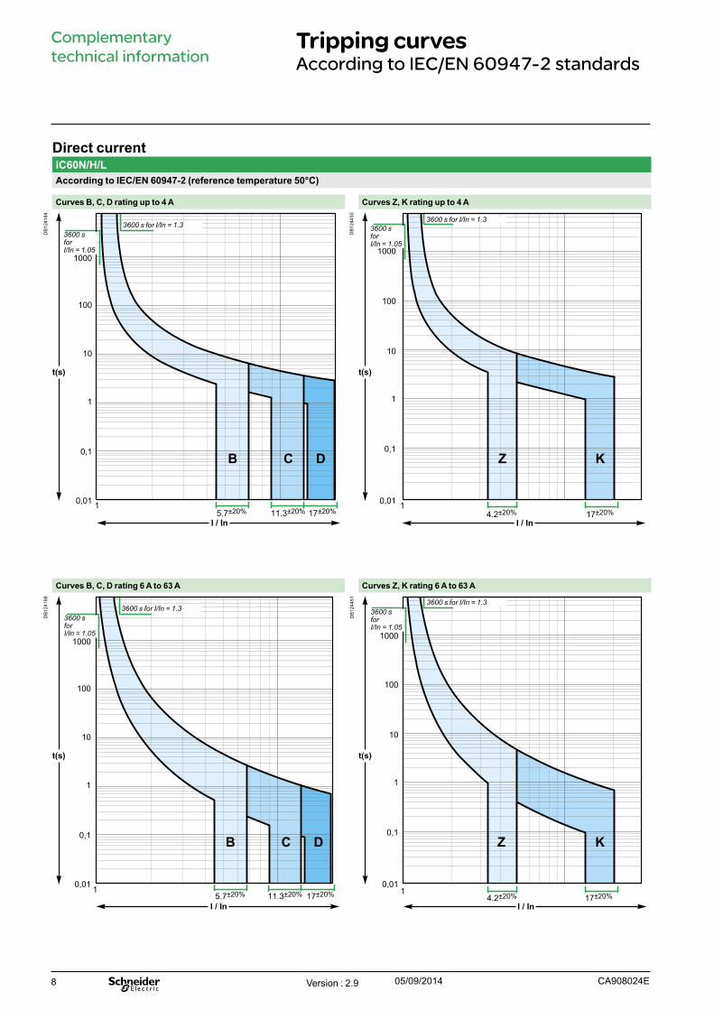
Complementary technical information
Tripping curvesAccording to IEC/EN 60947-2 standards
Direct currentiC60N/H/LAccording to IEC/EN 60947-2 (reference temperature 50°C)
Curves B, C, D rating up to 4 A Curves Z, K rating up to 4 A
DB
1241
84
t(s)
0,01
0,1
1
10
100
1000
I / In
1
B C D
5.7±20% 11.3±20% 17±20%
DB
1244
50
I / In
t(s)
0,01
0,1
1
10
100
1000
KZ
14.2±20% 17±20%
Curves B, C, D rating 6 A to 63 A Curves Z, K rating 6 A to 63 A
DB
1241
88
t(s)
0,01
0,1
1
10
100
1000
I / In
B C D
15.7±20% 11.3±20% 17±20%
DB
1244
51
I / In
t(s)
0,01
0,1
1
10
100
1000
KZ
14.2±20% 17±20%
3600 sforI/In = 1.05
3600 s for I/In = 1.3 3600 sforI/In = 1.05
3600 s for I/In = 1.3
3600 s for I/In = 1.33600 sforI/In = 1.05
3600 s for I/In = 1.33600 sforI/In = 1.05
Version : 2.9 05/09/2014 CA908024E
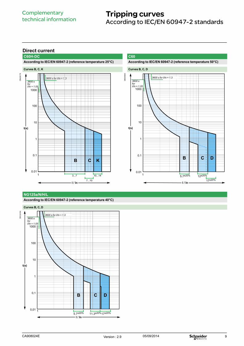
9
Complementary technical information
Tripping curvesAccording to IEC/EN 60947-2 standards
Direct currentC60H-DC C60According to IEC/EN 60947-2 (reference temperature 25°C) According to IEC/EN 60947-2 (reference temperature 50°C)
Curves B, C, K Curves B, C, D
DB
4061
78
t(s)
0.01
0.1
1
10
100
1000
I / In
1 3...7 10...14
7...10
B C K
DB
4058
40
t(s)
0.01
0.1
1
10
100
1000
I / In
1 5.7±20%
B C D
12±20%
17±20%
NG125a/N/H/LAccording to IEC/EN 60947-2 (reference temperature 40°C)
Curves B, C, D
DB
1241
84
t(s)
I / In
0,01
0,1
1
10
100
1000
C DB
15.7±20% 11.3±20%17±20%
3600 sforI/In = 1.05
3600 s for I/In = 1.3
3600 sforI/In = 1.05
3600 sforI/In = 1.05
3600 s for I/In = 1.33600 s for I/In = 1.3
Version : 2.9 05/09/2014CA908024E
10
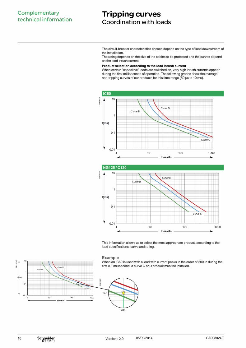
The circuit-breaker characteristics chosen depend on the type of load downstream of the installation.The rating depends on the size of the cables to be protected and the curves depend on the load inrush current. Product selection according to the load inrush current When certain "capacitive" loads are switched on, very high inrush currents appear during the first milliseconds of operation. The following graphs show the average non-tripping curves of our products for this time range (50 μs to 10 ms).
iC60D
B12
4249
Ipeak/In
t(ms)
0,01
0,1
1
10
100 1000101
Curve DCurve B
Curve C
NG125 / C120
DB
1242
50
t(ms)
0,01
0,1
1
10
100 1000101Ipeak/In
Curve DCurve B
Curve C
This information allows us to select the most appropriate product, according to the load specifications: curve and rating.
ExampleWhen an iC60 is used with a load with current peaks in the order of 200 In during the first 0.1 millisecond, a curve C or D product must be installed.
Ipeak/In
t(ms)
0,01
0,1
1
10
100 1000101
Curve DCurve B
Curve C
0,1
100 200 1000
0,1
200
Complementary technical information
Tripping curvesCoordination with loads
Version : 2.9 05/09/2014 CA908024E
DB
1242
51
DB
1242
49
11
Complementary technical information
Tripping curves
2.9 5/10/2014 Add DPN H page 3 JPM2.8 3/09/2013 Add RCBO in iC60 AC table page 5 Sedoc2.7 25/04/2013 Change IIn/ C60, (curve C60H-DC, C60) JPM2.6 11/03/2013 Changed C60H-DC curves page 9 Sedoc2.5 24/01/2013 Add page 10 "Coordination with loads" Sedoc2.4 13/07/2012 Add C60 curves Sedoc2.3 4/07/2012 Deleted C60 curves Sedoc2.2 06/06/2012 Change texts and add C60 curves Sedoc2.1 24/08/2011 Change Z, K curves pages 8 Sedoc2.0 23/05/2011 InDesign CS5 Sedoc1.2 16/04/2011 Add new curves C120, DPN, iK60, NG125, C60H-DC Sedoc1.1 25/03/2011 New curves Sedoc1.0 14/10/2009 Creation SedocIndice Date Modification Name
Evolutions
This page must be removed before publis
hing
Version : 2.9 05/09/2014CA908024E