tru disconnect ferrule and clamp details
TRANSCRIPT


TRU D I S C O m C T FERRULE AND CLAMP DETAILS
0, 0 , Yarbro
MAY 1965
OAK RIDG3 NATIONAL LABOWTQFL Oak Ridge, Tennessee
operated hy UNION CARBIDE CORPORATION
for the U,S , ATOMLC ENEHGX C Q M S S I O N
3 L145b 0 3 5 9 2 4 9 5


-iv-

-v-
Page
C-57624-rn Metal Bla& Off Plugs for 3/4" Ferrule Sizes, a 32
C-55833-R2 Metal Blank Off Plugs w i t h Tantalum Inserts for 314" F e s ~ d e S i z e s e a * . , = . . . e 6 33
c- 572'168 Inlet Nipples for Off-Gas and Waste Headers r e e 35
c - 5 755 7 andl /2"Sizes , I e a . . * e I + e E6
Plas t ic Disconnect t o Tube Adapter for 1/4''2 3/8'IJE
* These are considered standard sizeso Other ferrules are considered special ferrules or adaptors E


ABSTRACT
This memo includes a complete s e t of disconnect
clamp and ferrule drawings 09 the types t o be used i n the Transuranium Processing Plant, designs for connections i n stainless gteel, Wastelioy C,
tantalum and Zircaloy-2 fo r tubiag sizes of lib, 3/8-, J/2-$ and 3/h-inch OD and pipe s izes of 1/4, 3/8, and
Included are
z/2 inch.

-2-

-3-
Nomirzal. Major T i p U s u a l Connecting Line Size 'Tubing Pipe T i p Size Diameter

-4-
Y
GENERAL NOTES I
I. dirconncsh" Fmbrimtia and No. teding C i 41.1. oi this asrmbly iholl be in ocsoniona with "specification fw tubiw
2.
3.
Ports 1 m d 2 In the mush mst conditia h o l i bn sufficient makrioi to dlw for mackblng.
k t p i h of prh 6 and 7 sha l l be furnished by tine c m p n y to the seller fa bnctl-I opemttng test os rpsified in spec. CT 41.1.
The drilling of dl holes shall ba adorned in a drili jig fixture.
Moterials r b l l be rpc:ficd in spcifimtian CT 41.1.
Cart Surfaces: w ASA Fin;& &sisnotla 125RMS. t d t m c d with a maximum &ph of 1/32" with d i m e k n unnmisted. diameter are not suffisieotl~ rven to be sonsidered rrfeck d e n oaocioted with u-d m k r i o i (x clurkrcd in grwp of m m than 5 pcr 1/4* diameter. Defects in stacked m e a n , ruhequently mashinsa, ore reshickd to lhe dapth of the stock-
1.
5.
Cob rurfosai iholl bo in o s s d n c e vtth Alloy Catlng Imtituk's Gmdc C-30 Vliucl indimtimi in umtocted am= must b. cieor and
lndicotionr leu than .010"
T
~ ~ , . d : L H J A G C J D N Alanic Energy hiria
MAY BE CHOSEN BY FABRICATOR. 3. ROUGHNESS H E M OF M/\CHiHED
SURfACES SHALL NOT ELCECD 6g (FINISH ARE IN ACCORDANCE 9YMBOLS hHD WTH HElGIiT As* VALUES

-5-
I.
..

N
-12-

- 8-
-7-
E '1
cc j,.
8!6 .I .

I 0
I

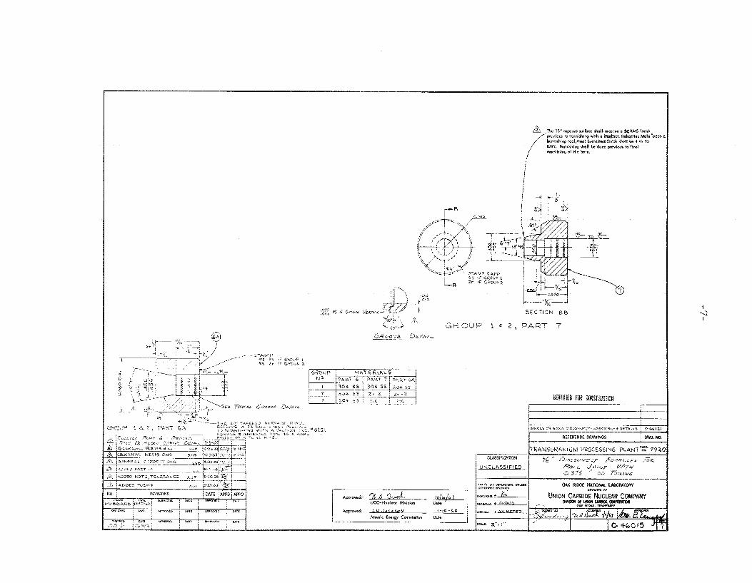
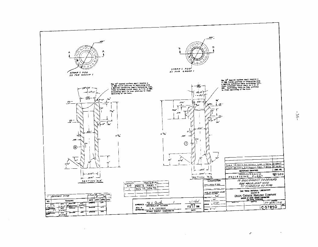
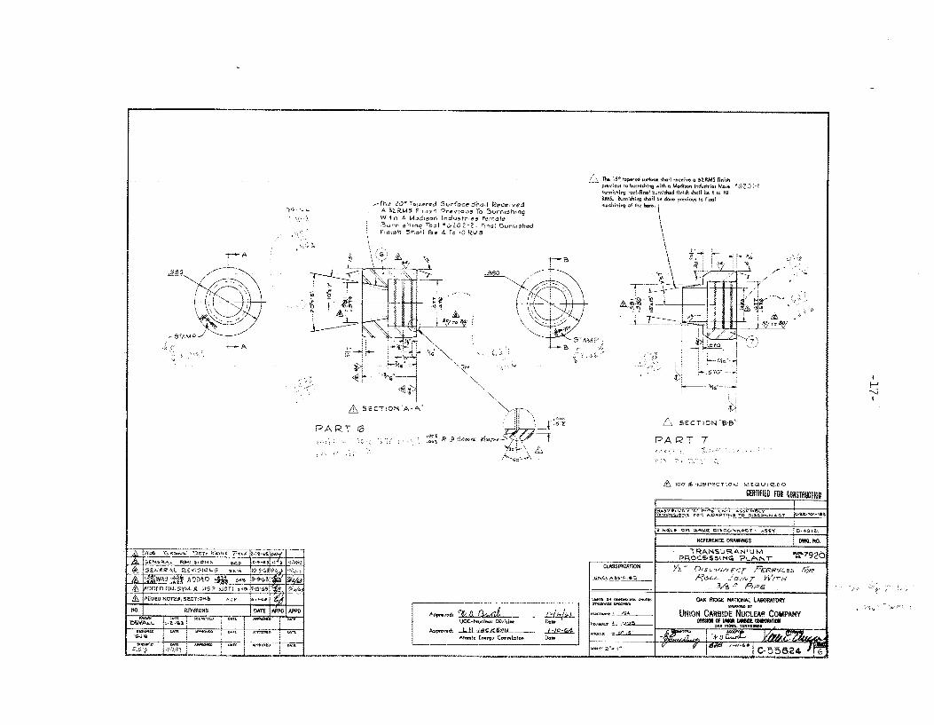
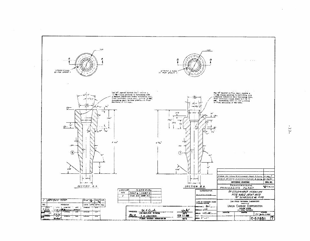
M 20" TAFEWD S W A C E SHI I I l . RECEIVE A 3P RW FINISH A(ByI0Us M
( V O - 62071 FINhL BURNISHED IINISH S W U RE 4 TO 10 RW FOR 1' BURRISHIK. WITH A WLDISON IRDUSTRIEJ =:Mw BURRISBINC TWL
i F'IHST 114" OF T h A H .
S6CTIOd @ L C - 5 2 1 5 9
G E O U P l e 2 P A E T A
I
L S T A M P 4 ADD 5 5 I F GRCUP 1 t r , F GRDUP 2
C 52159
C-52159
S E C T I O ~ ~
G~ZOUP : t 2 PAeT 7 I

L A
AS E CT ION'B-B'
I O 0 Yi I N S P E C T I O U R C P U I @ E O

- 12 .-
0
m
r
0
Q
4

-l3-
3
e O
vlN
N
*
0. 3
0
ol u
f QJ
Q
Y n
61:

- 14-
i
4 a I t J

I- -
I
-16-
I F A
L A
i-- %c--
J)i c?. SECTION 8 8
P A R T 7
I I-J -?

- 18-
0
10
? 0
41

G R O U P 1 e 2 P A R T 6 A
I Tu 0 I

PRRT c
L A

-zz-

-23
-

_-
I
REFERENCE DRAWINGS ~ DWGNO.


D
-9z-

ad
Q

I L 5/8 -
SECTION 'A-A"
PART 6
STAMP
1 5 IF G R O U P a 2 , IF GROUP 4

-29-
"+
f 'p

L- -%- S K T I ON *4.-A'
PART B
I STAMP HC I F GROUP 1 5 5 I F GROUP 2 Lt > F GROUP +
Si C T ION "8-8 PART 9

-31-
T-
3$
,2 ...
. ~ . . . . . . .
q*--
J

-32
-

I w w I

TOP VIEW
I REFERENCE DPAWNGS DWO. NO

a

I

1. 2, 3 . 4.