ef elephant feet ferrule concrete capacity method
TRANSCRIPT

EF ELEPHANT FEET FERRULE Concrete Capacity Method
Page 1
PRODUCT FEATURES • Stress-free anchoring close to edge and reduced anchor spacing. • Cast-in placement eliminates the need of drilling, important when the reinforcing is in the fi xing zone. • Ideal for shallow embedment as the anchor can be tied on the reinforcement for better load distribution over a wider area to become an integral part of the reinforcing structure. • Suitable for high tension, cracked concrete zone areas, pre- tensioning and post tensioning concrete structures. • High tension and shear load capacities with high tensile steel grade bolts. • Cross bar creates “ductile” failure behaviour to increase safety. • Excellent product replacement to cast-in channel for curtain wall fi xings. • Sizes available up to M30.
MATERIAL SPECIFICATIONS• Hot forged carbon steel; zinc galvanised ≥ 5µm & hot dipped galvanised ≥ 40µm.• Hot forged stainless steel 304 (A2) & 316 (A4).
SUBSTRATES• RC concrete C20/25 to C50/60 at maximum according to EN 206-1:2000-12.
LOADING ZONES
• For static and quasi-static loadings. • For cracked and non-cracked concrete. • Only a single anchor is considered. • No anchor spacing and edge distance infl uences. • Concrete compressive strength C20/25 (fck,cube = 25 N/mm2).
BASIC LOADING DATA FOR EF; EF-GH; EF-S & EF-SS
CHARACTERISTIC RESISTANCE [FRk]
Anchor Size M10x45 M12x55 M12x70 M16x70 M16x95 M20x70 M20x95 M24x95 M24x120 M30x125 M30x175
Non-Cracked Concrete
Tensile Load, NRk [kN] 13.5 18.2 26.1 32.3 51.0 35.1 55.5 69.5 92.0 106.2 125.7
Cracked Concrete
Tensile Load, NRk [kN] 9.6 12.9 18.6 23.0 36.4 25.0 39.6 49.5 65.6 75.7 89.6
Shear Load, VRk [kN]
~ Carbon Steel 17.4 25.3 25.3 47.1 47.1 73.5 73.5 105.9 105.9 155.8 155.8
~ Stainless Steel 24.4 35.4 35.4 65.9 65.9 102.9 102.9 148.3 148.3 218.0 218.0
DESIGN RESISTANCE [RRd]
Anchor Size M10x45 M12x55 M12x70 M16x70 M16x95 M20x70 M20x95 M24x95 M24x120 M30x125 M30x175
Non-Cracked Concrete
Tensile Load, NRd [kN] 9.0 12.1 17.4 21.5 34.0 23.4 37.0 46.3 61.3 70.8 83.8
Cracked Concrete
Tensile Load, NRd [kN] 6.4 8.6 12.4 15.3 24.2 16.7 26.4 33.0 43.7 50.5 59.7
Shear Load, VRd [kN]
~ Carbon Steel 13.9 20.2 20.2 37.7 37.7 58.8 58.8 84.7 84.7 124.6 124.6
~ Stainless Steel 15.6 22.7 22.7 42.3 42.3 66.0 66.0 95.0 95.0 139.7 139.7
RECOMMENDED LOAD [FRec]
Anchor Size M10x45 M12x55 M12x70 M16x70 M16x95 M20x70 M20x95 M24x95 M24x120 M30x125 M30x175
Non-Cracked Concrete
Tensile Load, NRec [kN] 6.4 8.6 12.4 15.4 24.3 16.7 26.4 33.1 43.8 50.6 59.9
Cracked Concrete
Tensile Load, NRec [kN] 4.6 6.2 8.9 10.9 17.3 11.9 18.8 23.6 31.2 36.1 42.7
Shear Load, VRec [kN]
~ Carbon Steel 9.9 14.5 14.5 26.9 26.9 42.0 42.0 60.5 60.5 89.0 89.0
~ Stainless Steel 11.2 16.2 16.2 30.2 30.2 47.1 47.1 67.9 67.9 99.8 99.8

EF ELEPHANT FEET FERRULE Concrete Capacity Method
Page 2
SETTING DETAILSANCHOR SIZE M10x45 M12x55 M12x70 M16x70 M16x95 M20x70 M20x95 M24x95 M24x120 M30x125 M30x175
Anchor Length, L [mm] 45 55 70 70 95 70 95 95 120 125 175
Thread Length, Lt [mm] 20 25 35 35 40 35 40 50 75 50 75
Recommended Torque, Tinst [Nm] 17 30 75 144 250 300
Embedment Depth, hnom [mm] 50 60 75 75 100 75 100 100 125 130 180
Effective Anchorage Depth, hef [mm] 39 47 62 60 85 60 85 80 105 105 155
Outer Diameter, d0 [mm] 16 17 22 26 32 42
Base Diameter, daf [mm] 19 22 29 32 38 48
Cross Hole Diameter, Ch [mm] 9 11 15
Bar Size At Cross Hole [mm] R8 R10 Y12
Minimum Concrete Thickness, hmin [mm] 70 85 105 105 145 105 145 145 180 160 265
Critical Anchor Spacing, scr [mm] 117 141 186 180 255 180 255 240 315 315 465
Minimum Anchor Spacing, smin [mm] 39 47 62 60 85 60 85 80 105 105 155
Critical Edge Distance, ccr [mm] 59 71 93 90 128 90 128 120 158 158 233
Minimum Edge Distance, cmin [mm] 39 47 62 60 85 60 85 80 105 105 155
SETTING DIAGRAM
daf do
ch
Lt
hnom
hmin
L
INSTALLATION PROCEDURES
1. Secure fi rmly the ferrule on the formwork and reinforcing system, if required. 2. Pour the concrete. 3. Upon concrete cured, remove the formwork leaving the ferrule fi rmly embedded. 4. Attach fi xture upon concrete cured.
The design bending moment is derived from MRd,s = MRk,s / γMs,N where the partial safety factor is 1.25 for carbon steel and 1.56 for stainless steel. The recommended bending
moment is derived from MRec,s = MRd,s / γF where the partial safety factor is 1.4.
MECHANICAL PROPERTIESANCHOR SIZE M10 M12 M16 M20 M24 M30
Cross Sectional Area, As [mm2] 58.0 84.3 157.0 245.0 353.0 519.0
Nominal Tensile Strength, fuk [N/mm2]
~ Carbon Steel 500 500 500 500 500 500
~ Stainless Steel 700 700 700 700 700 700
Elastic Moment Of Resistance, Wel [mm3] 62.3 109.2 277.5 540.9 935.5 1,668.0
Design Bending Moment, MRd,s [Nm]
~ Carbon Steel 29.9 52.4 133.2 259.6 449.0 800.6
~ Stainless Steel 33.5 58.8 149.4 291.3 503.7 898.2
EF ELEPHANT FEET FERRULE Concrete Capacity Method
Page 3
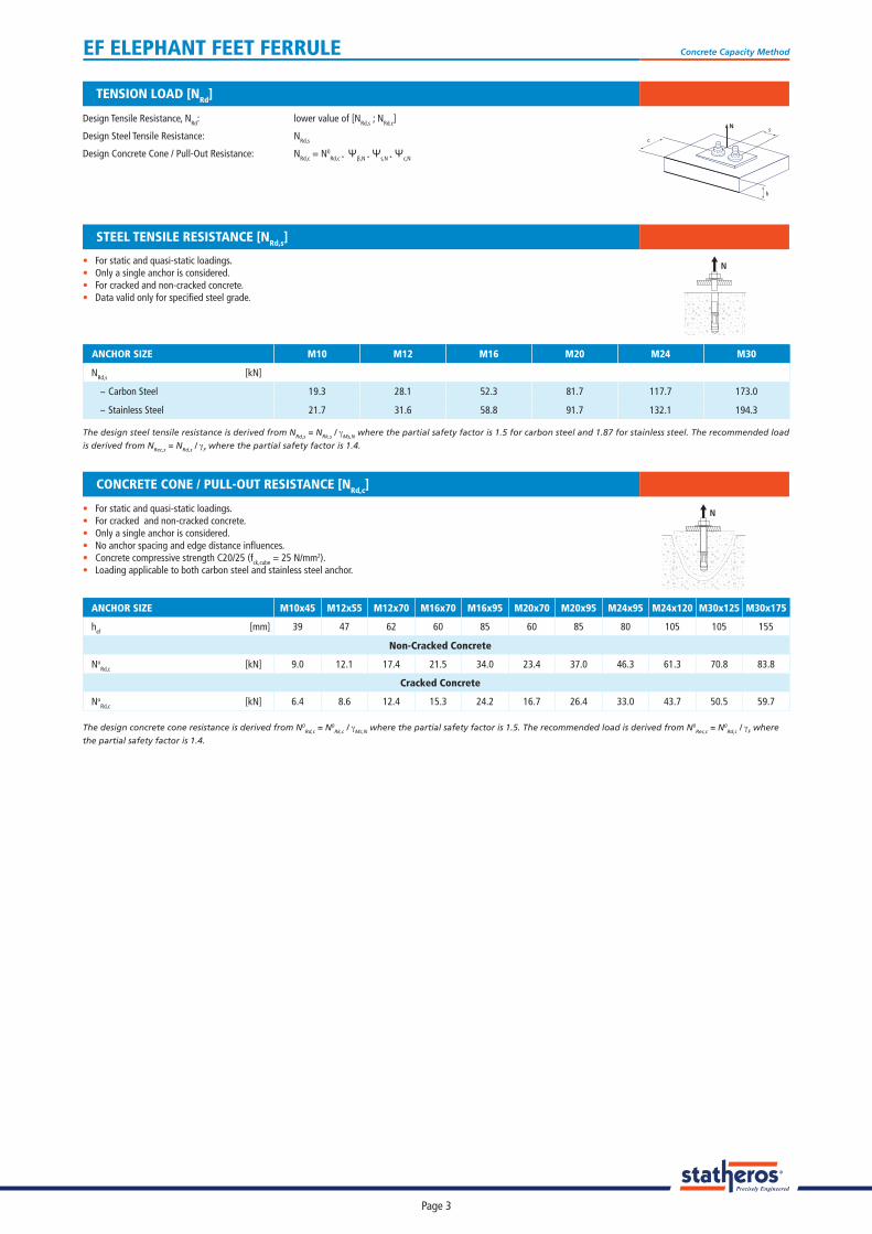
ANCHOR SIZE M10 M12 M16 M20 M24 M30
NRd,s [kN]
~ Carbon Steel 19.3 28.1 52.3 81.7 117.7 173.0
~ Stainless Steel 21.7 31.6 58.8 91.7 132.1 194.3
The design steel tensile resistance is derived from NRd,s = NRk,s / γMs,N where the partial safety factor is 1.5 for carbon steel and 1.87 for stainless steel. The recommended load
is derived from NRec,s = NRd,s / γF where the partial safety factor is 1.4.
• For static and quasi-static loadings. • Only a single anchor is considered. • For cracked and non-cracked concrete.• Data valid only for specifi ed steel grade.
STEEL TENSILE RESISTANCE [NRd,s]
N
TENSION LOAD [NRd]
Design Tensile Resistance, NRd: lower value of [NRd,s ; NRd,c]
Design Steel Tensile Resistance: NRd,s
Design Concrete Cone / Pull-Out Resistance: NRd,c = N0Rd,c * Ψβ,N * Ψs,N * Ψc,N
h
sN
c
• For static and quasi-static loadings.• For cracked and non-cracked concrete. • Only a single anchor is considered. • No anchor spacing and edge distance infl uences.• Concrete compressive strength C20/25 (fck,cube = 25 N/mm2). • Loading applicable to both carbon steel and stainless steel anchor.
CONCRETE CONE / PULL-OUT RESISTANCE [NRd,c]
The design concrete cone resistance is derived from N0Rd,c = N0
Rk,c / γMc,N where the partial safety factor is 1.5. The recommended load is derived from N0Rec,c = N0
Rd,c / γF where
the partial safety factor is 1.4.
ANCHOR SIZE M10x45 M12x55 M12x70 M16x70 M16x95 M20x70 M20x95 M24x95 M24x120 M30x125 M30x175
hef [mm] 39 47 62 60 85 60 85 80 105 105 155
Non-Cracked Concrete
NoRd,c [kN] 9.0 12.1 17.4 21.5 34.0 23.4 37.0 46.3 61.3 70.8 83.8
Cracked Concrete
NoRd,c [kN] 6.4 8.6 12.4 15.3 24.2 16.7 26.4 33.0 43.7 50.5 59.7
N

EF ELEPHANT FEET FERRULE Concrete Capacity Method
Page 4
Design Shear Resistance, VRd: lower value of [VRd,s ; VRd,c ; VRd,cp]
Design Steel Shear Resistance: VRd,s
Design Concrete Edge Shear Resistance: VRd,c = V0Rd,c * Ψβ,V * Ψα,V * Ψsc,V
Design Concrete Pry-Out Resistance: VRd,cp = V0Rd,cp * Ψβ,V * Ψs,N * Ψc,N
SHEAR LOAD [VRd]
h
s
V
c
The resultant force must be satisfi ed with the above conditions. The designer must cross check the loading conditions, types of applied loads and substrate to ensure the recommended anchor is applicable to the actual site applications. This would avoid any design faults which commonly caused by inconclusive load requirements with respective to actual site conditions.
COMBINED TENSION & SHEAR
Combined Tension & Shear:NSd VSd+ < 1.2NRd VRd
• For static and quasi-static loadings. • Only a single anchor is considered. • For cracked and non-cracked concrete.• Data valid only for specifi ed steel grade.
STEEL SHEAR RESISTANCE [VRd,s]
The design steel shear resistance is derived from VRd,s = VRk,s / γMs,v where the partial safety factor is 1.25 for carbon steel and 1.56 for stainless steel. The recommended load
is derived from VRec,s = VRd,s / γF where the partial safety factor is 1.4.
V
ANCHOR SIZE M10 M12 M16 M20 M24 M30
VRd,s [kN]
~ Carbon Steel 13.9 20.2 37.7 58.8 84.7 124.6
~ Stainless Steel 15.6 22.7 42.3 66.0 95.0 139.7
• For cracked and non-cracked concrete. • Only a single anchor is considered. • No anchor spacing and edge distance infl uences. • Single embedded depth is used for loading tabulation. • Concrete compressive strength C20/25 (fck,cube = 25 N/mm2). • Loading applicable to both carbon steel and stainless steel anchor.
The design concrete edge shear resistance is derived from V0Rd,c = V0
Rk,c / γMc,V where the partial safety factor is 1.5. The recommended load is derived from V0Rec,c = V0
Rd,c / γF
where the partial safety factor is 1.4.
CONCRETE EDGE SHEAR RESISTANCE [VRd,c]
V
ANCHOR SIZE M10x45 M12x55 M12x70 M16x70 M16x95 M20x70 M20x95 M24x95 M24x120 M30x125 M30x175
hef [mm] 39 47 62 60 85 60 85 80 105 105 155
cmin [mm] 39 47 62 60 85 60 85 80 105 105 155
Non-Cracked Concrete
VoRd,c [kN] 4.4 6.0 9.1 9.9 16.7 10.7 18.1 18.3 27.6 31.6 56.7
Cracked Concrete
VoRd,c [kN] 3.1 4.3 6.5 7.0 11.8 7.6 12.8 13.0 19.5 22.4 40.1
V
The design concrete pry-out resistance is derived from V0Rd,cp = V0
Rk,cp / γMp,v where the partial safety factor is 1.5. The recommended load is derived from V0Rec,cp = V0
Rd,cp / γF
where the partial safety factor is 1.4.
• For cracked and non-cracked concrete. • Only a single anchor is considered. • No anchor spacing and edge distance infl uences. • Single embedded depth is used for loading tabulation. • Concrete compressive strength C20/25 (fck,cube = 25 N/mm2). • Loading applicable to both carbon steel and stainless steel anchor.
CONCRETE PRY-OUT RESISTANCE [VRd,cp]
ANCHOR SIZE M10x45 M12x55 M12x70 M16x70 M16x95 M20x70 M20x95 M24x95 M24x120 M30x125 M30x175
hef [mm] 39 47 62 60 85 60 85 80 105 105 155
Non-Cracked Concrete
VoRd,cp [kN] 9.0 12.1 34.8 43.0 68.0 46.8 74.0 92.6 122.6 141.6 167.6
Cracked Concrete
VoRd,cp [kN] 6.4 8.6 24.8 30.7 48.5 33.4 52.8 66.0 87.4 101.0 119.5
EF ELEPHANT FEET FERRULE Concrete Capacity Method
Page 5
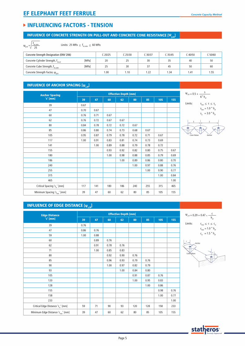
INFLUENCING FACTORS - TENSION
Anchor Spacing ‘s’ [mm]
Effective Depth [mm]
39 47 60 62 80 85 105 155
39 0.67
47 0.70 0.67
60 0.76 0.71 0.67
62 0.76 0.72 0.67 0.67
80 0.84 0.78 0.72 0.72 0.67
85 0.86 0.80 0.74 0.73 0.68 0.67
105 0.95 0.87 0.79 0.78 0.72 0.71 0.67
117 1.00 0.91 0.83 0.81 0.74 0.73 0.69
141 1.00 0.89 0.88 0.79 0.78 0.72
155 0.93 0.92 0.82 0.80 0.75 0.67
180 1.00 0.98 0.88 0.85 0.79 0.69
186 1.00 0.89 0.86 0.80 0.70
240 1.00 0.97 0.88 0.76
255 1.00 0.90 0.77
315 1.00 0.84
465 1.00
Critical Spacing ‘scr’ [mm] 117 141 180 186 240 255 315 465
Minimum Spacing ‘smin’ [mm] 39 47 60 62 80 85 105 155
INFLUENCE OF ANCHOR SPACING [ψs,N]
ψs,N = 0.5 +
Limits:
s
6* hef
smin < s < scr smin = 1.0 * hef scr = 3.0 * hef
S S
AnchorCone Failure
Edge Distance ‘c’ [mm]
Effective Depth [mm]
39 47 60 62 80 85 105 155
39 0.76
47 0.86 0.76
59 1.00 0.88
60 0.89 0.76
62 0.91 0.78 0.76
71 1.00 0.85 0.83
80 0.92 0.90 0.76
85 0.96 0.93 0.79 0.76
90 1.00 0.97 0.82 0.79
93 1.00 0.84 0.80
105 0.91 0.87 0.76
120 1.00 0.95 0.83
128 1.00 0.86
155 0.98 0.76
158 1.00 0.77
233 1.00
Critical Edge Distance ‘ccr’ [mm] 59 71 90 93 120 128 158 233
Minimum Edge Distance ‘cmin’ [mm] 39 47 60 62 80 85 105 155
INFLUENCE OF EDGE DISTANCE [ψc,N]
Limits:
ψc,N = 0.29 + 0.47 * c
hef
cmin < c < ccr cmin = 1.0 * hef ccr = 1.5 * hef
c
c
Anchor
Cone Failure
Concrete Strength Designation (ENV 206) C 20/25 C 25/30 C 30/37 C 35/45 C 40/50 C 50/60
Concrete Cylinder Strength, fck,cyl [MPa] 20 25 30 35 40 50
Concrete Cube Strength, fck,cube [MPa] 25 30 37 45 50 60
Concrete Strength Factor, ψβ,N 1.00 1.10 1.22 1.34 1.41 1.55
INFLUENCE OF CONCRETE STRENGTH ON PULL-OUT AND CONCRETE CONE RESISTANCE [Ψβ,N]
Limits: 25 MPa < fck,cube < 60 MPaψβ,N =fck,cube
25
EF ELEPHANT FEET FERRULE Concrete Capacity Method
Page 6
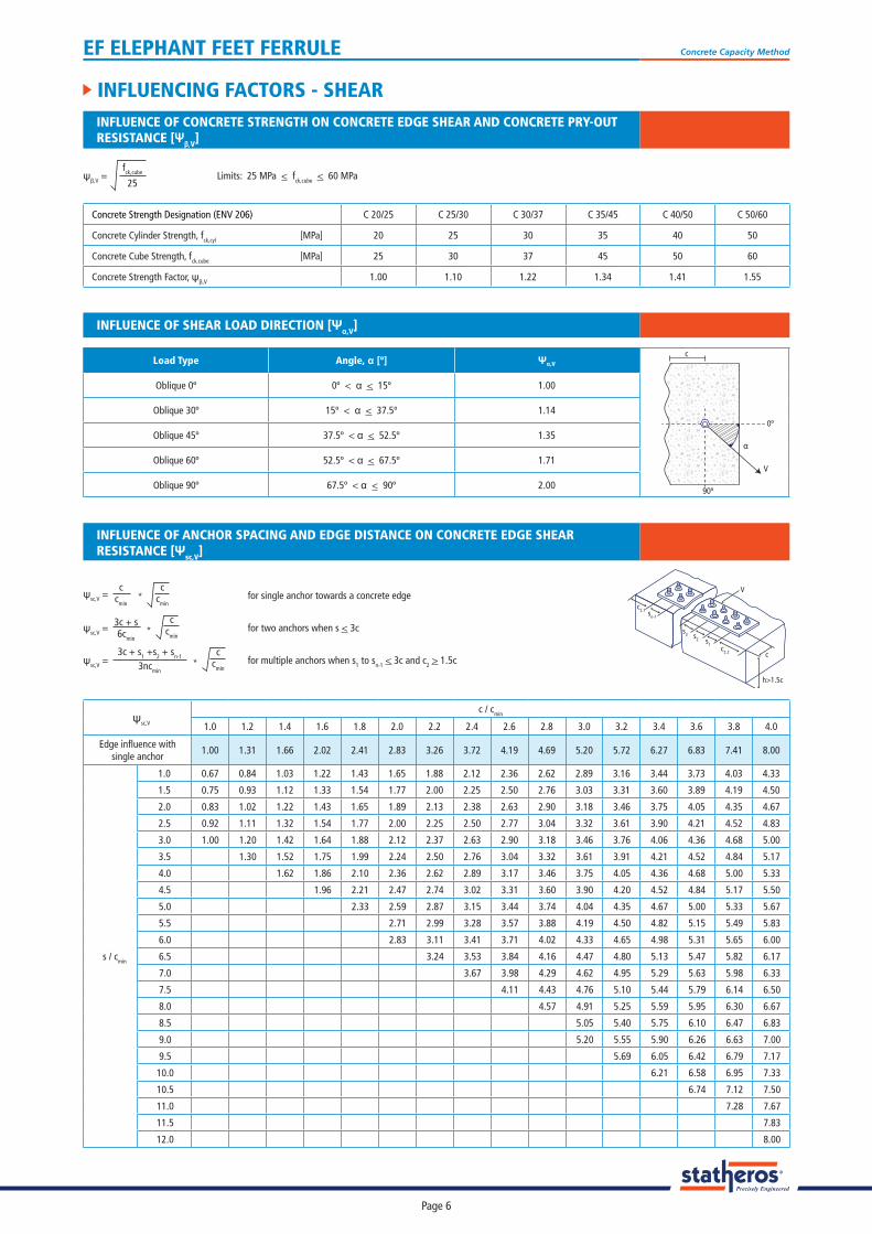
INFLUENCING FACTORS - SHEAR
ψsc,V
c / cmin
1.0 1.2 1.4 1.6 1.8 2.0 2.2 2.4 2.6 2.8 3.0 3.2 3.4 3.6 3.8 4.0
Edge infl uence withsingle anchor
1.00 1.31 1.66 2.02 2.41 2.83 3.26 3.72 4.19 4.69 5.20 5.72 6.27 6.83 7.41 8.00
s / cmin
1.0 0.67 0.84 1.03 1.22 1.43 1.65 1.88 2.12 2.36 2.62 2.89 3.16 3.44 3.73 4.03 4.33
1.5 0.75 0.93 1.12 1.33 1.54 1.77 2.00 2.25 2.50 2.76 3.03 3.31 3.60 3.89 4.19 4.50
2.0 0.83 1.02 1.22 1.43 1.65 1.89 2.13 2.38 2.63 2.90 3.18 3.46 3.75 4.05 4.35 4.67
2.5 0.92 1.11 1.32 1.54 1.77 2.00 2.25 2.50 2.77 3.04 3.32 3.61 3.90 4.21 4.52 4.83
3.0 1.00 1.20 1.42 1.64 1.88 2.12 2.37 2.63 2.90 3.18 3.46 3.76 4.06 4.36 4.68 5.00
3.5 1.30 1.52 1.75 1.99 2.24 2.50 2.76 3.04 3.32 3.61 3.91 4.21 4.52 4.84 5.17
4.0 1.62 1.86 2.10 2.36 2.62 2.89 3.17 3.46 3.75 4.05 4.36 4.68 5.00 5.33
4.5 1.96 2.21 2.47 2.74 3.02 3.31 3.60 3.90 4.20 4.52 4.84 5.17 5.50
5.0 2.33 2.59 2.87 3.15 3.44 3.74 4.04 4.35 4.67 5.00 5.33 5.67
5.5 2.71 2.99 3.28 3.57 3.88 4.19 4.50 4.82 5.15 5.49 5.83
6.0 2.83 3.11 3.41 3.71 4.02 4.33 4.65 4.98 5.31 5.65 6.00
6.5 3.24 3.53 3.84 4.16 4.47 4.80 5.13 5.47 5.82 6.17
7.0 3.67 3.98 4.29 4.62 4.95 5.29 5.63 5.98 6.33
7.5 4.11 4.43 4.76 5.10 5.44 5.79 6.14 6.50
8.0 4.57 4.91 5.25 5.59 5.95 6.30 6.67
8.5 5.05 5.40 5.75 6.10 6.47 6.83
9.0 5.20 5.55 5.90 6.26 6.63 7.00
9.5 5.69 6.05 6.42 6.79 7.17
10.0 6.21 6.58 6.95 7.33
10.5 6.74 7.12 7.50
11.0 7.28 7.67
11.5 7.83
12.0 8.00
INFLUENCE OF ANCHOR SPACING AND EDGE DISTANCE ON CONCRETE EDGE SHEAR RESISTANCE [Ψsc,V]
for single anchor towards a concrete edgeψsc,V = *c
cmin
ccmin
for two anchors when s < 3cc
cminψsc,V = *
3c + s6cmin
for multiple anchors when s1 to sn-1 < 3c and c2 > 1.5cc
cminψsc,V = *
3c + s1 +s2 + sn-1
3ncmin
c
c2.1
c2.2
sn-1
s3 s2 s1
h>1.5c
V
Concrete Strength Designation (ENV 206) C 20/25 C 25/30 C 30/37 C 35/45 C 40/50 C 50/60
Concrete Cylinder Strength, fck,cyl [MPa] 20 25 30 35 40 50
Concrete Cube Strength, fck,cube [MPa] 25 30 37 45 50 60
Concrete Strength Factor, ψβ,V 1.00 1.10 1.22 1.34 1.41 1.55
ψβ,V = Limits: 25 MPa < fck,cube < 60 MPafck,cube
25
INFLUENCE OF CONCRETE STRENGTH ON CONCRETE EDGE SHEAR AND CONCRETE PRY-OUTRESISTANCE [Ψβ,V]
INFLUENCE OF SHEAR LOAD DIRECTION [Ψα,V]
Load Type Angle, α [º] Ψα,V
Oblique 0º 0º < α < 15º 1.00
Oblique 30º 15º < α < 37.5º 1.14
Oblique 45º 37.5º < α < 52.5º 1.35
Oblique 60º 52.5º < α < 67.5º 1.71
Oblique 90º 67.5º < α < 90º 2.0090º
V
α
0º
c