trulok brochure - ljudisolering trulok suspension systems are manufactur ed for armstr ong both by...
TRANSCRIPT

CEILING SYSTEMS
Between us, ideas become reality® May 2009CI/SfB (35) Xy
www.armstrong-ceilings.iewww.armstrong-ceilings.co.uk
TRULOK Brochure
SUSPENSION SYSTEMS

A R M S T R O N G S U S P E N S I O N S Y S T E M S
Armstrong’s Philosophies 1Armstrong’s Commitment to the Environment 2CE Marking 3The Trulok Range 4
P R O D U C T R A N G E
DESIGN OPTIONS
Axiom Transitions 8Axiom Profiles 9Axiom Classic Canopy 10Axiom Knife Edge Canopy 12Silhouette 15 XL2 14Interlude 15 XL2 16
GENERAL APPLICATIONS
Prelude 15 18Prelude 24 XL2 20Prelude 24 TLX 22Prelude Sixty2 24Prelude 35 26 Bandraster 28System Z 30Drywall Grid System 32
CORRIDOR
Drywall Grid System 34Prelude Sixty2 35
SPECIFIC APPLICATIONS
Clean Room 24mm Grid System 36Corrosive Resistant 24rmm Grid System 37LongSpan System 38
METAL APPLICATIONS
Orcal 1800 System - (For Clip-In 5mm) 40Orcal 3000 System - (For Clip-In 3mm) 42Orcal 3000 System - (For Fastrak) Clip-In 44
PERIMETER TRIM AND ACCESSORIES
Perimeter Solutions - Mineral Ceilings 46Perimeter Solutions - Metal Ceilings 48Accessories 49
SUPPORT INFORMATION
Fire Tests 55Load Capacity Matrix 56
Designed for fast and easy
installation
Environment Q
uality/CE M
arking
Inno
vatio
n
Service
P
roduct
SUMMARY

TOTAL CEILING SOLUTIONS
The Trulok suspension system product range forms an integralpart of Armstrong’s total ceiling solutions policy. Armstrong nowoffers its customers and specifiers a complete range of ceilingpanels including mineral, soft fibre, wood and metal and a widerchoice than ever of suspension systems. Armstrong can providesolutions for all elements in today’s challenging constructionenvironments.
QUALITYTrulok suspension systems are manufactured for Armstrong bothby its joint venture company WAVE (Worthington ArmstrongVenture) and through various alliances with other companies who are regarded as specialists in their fields of engineering.
WAVE operates on a global basis, and brings to its variousEuropean operations world class practice on the mosttechnologically advanced equipment.
INTEGRATIONTrulok suspension systems are designed for integration withArmstrong's portfolio of ceiling products, mineral, soft fibre,metal, wood and special solutions.
SERVICETrulok suspension systems are manufactured in three Europeanplants, strategically located to serve all our European customers.Additionally, both Armstrong and WAVE can draw upon theirglobal manufacturing capabilities for both speciality products and manufacturing support.
In addition to WAVE’s manufacturing sites, Armstrong stockssuspension systems in distribution centres throughout Europe.This allows our customers the convenience of mixed productshipments, combining suspension systems with other Armstrongceiling products, optimising bulk shipments direct from theirmanufacturing locations.
WAVE WAVE has three manufacturing locations in Europe, three in theUSA including the facility in Aberdeen, Maryland which is one ofthe world’s largest grid facilities, plus one in China.
ARMSTRONG'S PHILOSOPHIES
Metal ceiling plants
Mineral fibre plants
Grid plants
Distribution centres
STAFFORD
TEAM VALLEY
MUNSTER
GRONINGENVALENCIENNES
MADRID
ST GALLEN / RANKWEILPONTARLIER
LAS VEGAS
BENTON HARBOUR
ABERDEEN / MALVERN
SHANGHAI
1

ARMSTRONG’S COMMITMENT TO THE ENVIRONMENTOur environmental efforts in the life-cycle of our products start with design.
DESIGN• Innovative design creates stronger sections.• Reuse of waste materials in new ceilings.• Raw materials for ceilings are renewable and abundant in nature.• Recycled content varies by product:- Suspension system - contain 25% recycled content- Metal - metal ceilings have an average of 25% recycled content- Mineral fibre - commercial application mineral fibre ceilings up to 75%- Fibreglass - ceilings contain 25% post
industrial recycled glass
MANUFACTURING• Suspension system Main Runners and Cross Tees
are rotary stitched by a patented method to deliver extra strength and stability.
• All in process scrap is recycled back into the process.• Almost all the process water is recycled. Only a minimal
amount of water is discharged, and only after proper treatment.
• Suspension systems and panels are manufactured at several locations, thereby reducing transportation costs and environmental impacts associated with transportation.
INSTALLATION• Integrate technology to reduce installation time.• Minimal packing material used.• Up to 100% of the packaging is made from
recycled material. In several countries, we support the recollection of packaging.
MAINTENANCE• Improve lighting, lower cost and conserve energy with high light reflectant ceilings.• Minimal maintenance and easy to replace.• Armstrong has an expanding portfolio of sustainable products, these include:
> Hot-dipped galvanised suspension systems provide superior resistance to rust and corrosion.
> Damage-resistant ceilings- Scrubbability- Washability- Soil resistance- Impact & scratch resistance- Inhibit or retard mould & mildew on ceiling surface with Armstrong’s Bioguard tiles.
WARRANTY ON USE• A history of quality products.• Various warranty options are available on
ceilings systems.
RETHINK PRODUCTS• Continuous development of innovative
thin gauge products.
RECYCLE• Suspension systems contain up to 25%
recycle content.• End of Life ceiling tile recycling scheme.
2

BRE BUILDING RESEARCHESTABLISHMENT As the World’s foremost producer of suspended ceiling systems,we know how important it is to be transparent in regard to theimpact our operations have on the environment.
Claims are easy to make but difficult to substantiate without an independent,universal measuring system. BRE initiated a scheme compliant with ISO 14041which provides Environmental Profiling, allowing end users and manufacturers toassess the environmental performance of selected products.
Starting in 2004 we commissioned BRE to profile our UK ceiling and gridmanufacturing facilities and products.
BRE assess this impact using an ‘Ecopoint’ score based on a product’s rawmaterials and manufacturing processes. These are then measured against keycriteria.....
Our rating was 0.16 Ecopoints giving a lower environmental impact compared withBRE’s generic norm of 0.22 (based upon 1m2 of 600x600 ceiling panel and Trulok grid).
At that time the “Green Guide to Specification” included suspended ceilings andthis resulted in an ‘A’ rating – the best available.
BRE’s system of profiling has since progressed to reflect the needs of developingEuropean and International standards. It now complies with ISO 21930, theforthcoming standard for analysing the impacts of construction products.
Therefore, during 2007 we updated our Environmental Profile using BRE’s newmethodology and are delighted that our Ecopoints rating of 0.16 has reduced byapprox 40% to 0.10 Ecopoints. This reflects our continuing focus on processesand selection of raw materials.
All grid plants have been certified ISO 14001:2004 certified process
What is it ?
CE stands for Conformité Européenne, whichtranslated literally, means “European Conformity”.
The CE mark is a products “passport” for entry into the EEA (European Economic Area)and indicates that the product complies with the requirements of the applicable EuropeanDirective.
For construction products the European Directiveis the Construction Products Directive(89/106/EEC).
The CPD identifies the essential requirements forproducts (and total projects) such that they are fitfor intended use as:
• Mechanical resistance and stability
• Safety in case of fire
• Hygiene, health and environment
• Safety in use
• Protection against noise
• Energy economy and heat retention
For suspended ceilings, the way in which wemust test and communicate performance forthese essential requirements has been defined ina new standard published in the “Official Journal”
EN 13964 Suspended Ceilings –
Requirements and Test Methods.
What does this mean?This standard identifies how the ceilingcomponents must be tested against theessential requirements to identify a performanceclassification. It also indicates how themanufacturer must ensure that their productsmaintain these levels of performance on anongoing basis.
On 1st July 2007, it became mandatory for allsuspended ceilings and accompanyingsuspension systems (in the scope of EN 13964)to carry the CE mark and the accompanyingessential requirement test information.
From 1st July 2007, onwards, non-CE markedmaterials are no longer saleable into the EEA.
Climate ChangeWater ExtractionMineral Resource ExtractionStratospheric Ozone DepletionHuman ToxicityEcotoxicity to FreshwaterNuclear Waste (higher level)Ecotoxicity to Land
Waste Disposal Fossil FuelDepletionEutrophicationPhotochemical Ozone CreationAcidification
(BRE 2008 Methodology)
BRE C
er t
i fi c a t i o n L
i mited
CE marking
3

THE TRULOK RANGE
The Trulok range includes a full range of solutions for all ceilingsuspension requirements:
- General applications, a range of standard Prelude 24mm and Prelude 15mm grid systems, Bandraster and Prelude Sixty2 for longer spans. Drywall Grid Systems are available for plasterboard ceilings.
- Designer options including the minimalist grid Silhouette, Interlude and the Axiom range.
- Specific applications, for clean room and higher humidity environments.
- Perimeter trims and accessories, for most applications.
We also include our comprehensive programme of special sizeoptions that is available in most ranges. A range of either stabor hook systems are available to meet the mechanicalpreferences of the installer.
To complete the portfolio we also offer a technical testprogramme that provides fire, loadings and environmentalaccreditation. Trulok suspension systems are designed for usewith a wide variety of Armstrong ceiling products, mineral, softfibre, metal, wood and special solutions.
Peakform is an innovative design for Main Runners and CrossTees. The taller Peakform profiles are engineered to create astronger, more stable suspension system making installationboth faster and easier.
Superlock is an industry first staked-on clip for Main Runnerswhich provide tighter, secure bulb-to-bulb connections;connections are confirmed by an audible click; Main Runnersare easily disconnected and reconnected laterally.
Prelude Universal Main Runner
The Prelude Universal Main Runner supports the installation ofeither hook/butt cut or stab/override Cross Tees from onesimple inventory of Main Runners. The universal system isavailable in Peakform design in both 24mm and 15mmwidths. The Peakform Universal Main Runners feature a firm,quick and easy assembled Main Runner to Main Runner / bulb-to-bulb connection. Metric sized Main Runners are slotted at100mm centres for more flexibility. Slots are machined to
receive positive and accurate assembly of either Prelude TLand TLX (hook installation) or Prelude XL2 (stab installation)Cross Tees. The staked-on Superlock clip allows for MainRunners to be disconnected and reconnected laterally in low-clearance areas or in the middle of a room.
TLX
TL
XL2
4 www.armstrong-ceilings.co.uk www.armstrong-ceilings.ie

Prelude XL2 “click” installation
Prelude XL2 Cross Tees in both 24mm and 15mm widthsfeature an advanced stab system that locates with an audible“click”, ensuring a solid installation at all times. The stab end isprecision stamped from a separate piece of high grade steelpermitting an increased accuracy and economy of productionover the more conventional integral forming of the Cross Teeends. A selected range of standard Prelude 15/24 XL2 CrossTees feature the new Peakform design.
The Cross Tees are inserted to the right of each other throughthe Main Runner slots and easily pushed home.
Prelude TL “hook” installation
Prelude TL Cross Tees in 15mm width feature an integrallyformed hook nose. This popular installation system has beena feature of Armstrong Trulok suspension systems for over 20 years and its proven ease of assembly and precise butt cutjoint has been a favourite of installers. Cross Tee alignment isensured by locating the tees to the right hand side of theadjoining section.
Prelude TLX
The TLX clip is a new highly engineered staked-on hook clip,with a patented clip.
Its unique steel-based composite material and shape providea stronger and level connection, an improved fire performanceand an increased overall stability.
TLX Cross Tees are quicker and easier to cut due to thePeakform section. When the TLX Cross Tees are inserted tothe right of each other through the Main Runner slots, the TLX clip provides a more secure installation.
Drywall Grid System
The Drywall Grid System (DGS) is a quick and easy to installsuspension system for plasterboard ceilings and is available ina range of three unique systems; Standard, Faceted &Shortspan.
- Standard DGS: For standard flat plasterboard installations
- Faceted DGS: For curved plasterboard and domed ceilings
- Shortspan: For small areas in both commercial and residential installations, including corridors
This alternative suspension system for drywall installation cansave up to 40% in installation time.
WHERE INNOVATION MEETS PERFORMANCE
5www.armstrong-ceilings.co.uk www.armstrong-ceilings.ie

Hot Dipped Galvanized Steel:
Inhibits red rusting better and longer than electro galvanised orpainted systems
• Installation of grid can start before the building is enclosed or HVAC system is operational.
• Long term system performance because entire system is hot dipped galvanised steel.
Thin gauge technology:
Up to 50% lighter carton weight than the competition enables easier handling on site, plus the added benefit of the Peakform bulb allows easy cutting of the grid.
Designer Grids
Armstrong’s designer range, Silhouette, Interlude, Axiom Systemand Axiom Canopies provide aesthetically enhanced grids.Silhouette creates a level ceiling surface, providing a flushappearance while Interlude gives a clean sophisticated visual thatis created by the unique double reveal. Axiom Profiles andTransitions provide an aesthetic solution for changes in level anda flush transition with plaster margins. Axiom Canopies are aperimeter trim system designed to create “ceiling clouds” inconjunction with full size tiles.
Other systems
Trulok’s extensive range of performance grids also includesBandraster, Prelude Sixty2, Prelude 35, System Z and LongSpan.Specific grid solutions such as CLEAN ROOM Grid and CorrosiveResistant grid completes Armstrong's Trulok suspension solutions.
Physical detail
All grids are made from double-web galvanised steel with asurface finish of baked polyester paint.
Stitching
All Prelude components feature a unique “stitched” construction. The two metal layers of the vertical web are mechanically lockedtogether in a sophisticated in-lineprocess. Stitching enhances the torsional resistance and general “feel” of the Prelude components.
Full range of accessories and perimeter solutions
Trulok suspension systems are offered with a complete range of commonly required accessories and perimeter solutions.
Standard ColourTrulok suspension system components are manufactured in a range of colours and metal finishes including Global White to complement Armstrong
ceiling tiles. For complete information call Internal Technical Sales.
GLOBAL WHITE SILVER GREY CARRARA PLATINUM BLACK WHITE GLOBAL WHITE BRASS CHROME WHITE GALVANISED KNURLED BLACK/WHITE(GW) RAL 9006 (SG) (CA) (PN) (BK) RAL9010 (WR) (GW) (BS) (CE) RAL9010 (WR)
Prelude 24 TLX
Prelude 24 XL2
Prelude 15 XL2
Silhouette XL2 6mm
Silhouette XL2 3mm
Interlude
Bandraster
Prelude 35
Prelude Sixty2
Corrosive Resistant
CLEAN ROOM Grid
Axiom System
Steel based capping Other than Steel based
Painted perimeter trim items are available in Global White and capped angle BPT 1924 CA is available in all colours except black/white, galvanised and knurled.Please contact Internal Technical Sales Group for further details.
WHERE INNOVATION MEETS PERFORMANCE
6
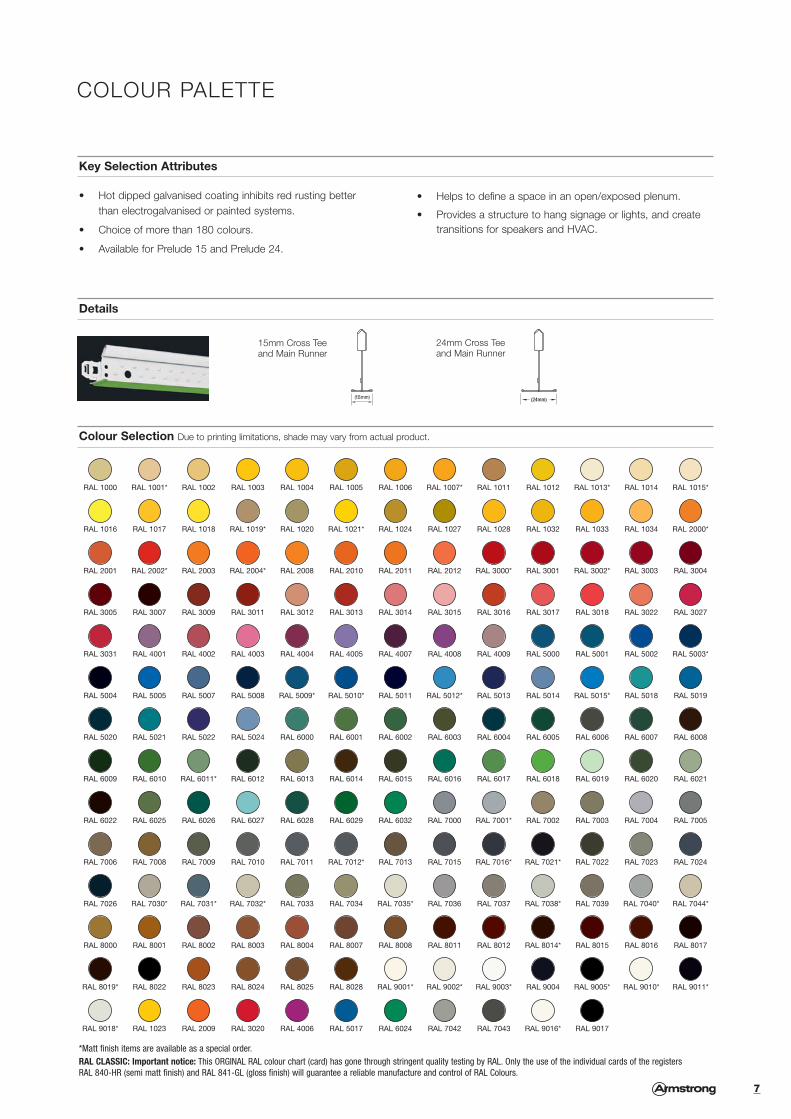
Key Selection Attributes
• Hot dipped galvanised coating inhibits red rusting better than electrogalvanised or painted systems.
• Choice of more than 180 colours.
• Available for Prelude 15 and Prelude 24.
• Helps to define a space in an open/exposed plenum.
• Provides a structure to hang signage or lights, and create transitions for speakers and HVAC.
Details
Colour Selection Due to printing limitations, shade may vary from actual product.
COLOUR PALETTE
15mm Cross Tee and Main Runner
24mm Cross Tee and Main Runner
*Matt finish items are available as a special order.RAL CLASSIC: Important notice: This ORGINAL RAL colour chart (card) has gone through stringent quality testing by RAL. Only the use of the individual cards of the registersRAL 840-HR (semi matt finish) and RAL 841-GL (gloss finish) will guarantee a reliable manufacture and control of RAL Colours.
RAL 1000 RAL 1001* RAL 1002 RAL 1003 RAL 1004 RAL 1005 RAL 1006 RAL 1007* RAL 1011 RAL 1012 RAL 1013* RAL 1014 RAL 1015*
RAL 1016 RAL 1017 RAL 1018 RAL 1019* RAL 1020 RAL 1021* RAL 1024 RAL 1027 RAL 1028 RAL 1032 RAL 1033 RAL 1034 RAL 2000*
RAL 2001 RAL 2002* RAL 2003 RAL 2004* RAL 2008 RAL 2010 RAL 2011 RAL 2012 RAL 3000* RAL 3001 RAL 3002* RAL 3003 RAL 3004
RAL 3005 RAL 3007 RAL 3009 RAL 3011 RAL 3012 RAL 3013 RAL 3014 RAL 3015 RAL 3016 RAL 3017 RAL 3018 RAL 3022 RAL 3027
RAL 3031 RAL 4001 RAL 4002 RAL 4003 RAL 4004 RAL 4005 RAL 4007 RAL 4008 RAL 4009 RAL 5000 RAL 5001 RAL 5002 RAL 5003*
RAL 5004 RAL 5005 RAL 5007 RAL 5008 RAL 5009* RAL 5010* RAL 5011 RAL 5012* RAL 5013 RAL 5014 RAL 5015* RAL 5018 RAL 5019
RAL 5020 RAL 5021 RAL 5022 RAL 5024 RAL 6000 RAL 6001 RAL 6002 RAL 6003 RAL 6004 RAL 6005 RAL 6006 RAL 6007 RAL 6008
RAL 6009 RAL 6010 RAL 6011* RAL 6012 RAL 6013 RAL 6014 RAL 6015 RAL 6016 RAL 6017 RAL 6018 RAL 6019 RAL 6020 RAL 6021
RAL 6022 RAL 6025 RAL 6026 RAL 6027 RAL 6028 RAL 6029 RAL 6032 RAL 7000 RAL 7001* RAL 7002 RAL 7003 RAL 7004 RAL 7005
RAL 7006 RAL 7008 RAL 7009 RAL 7010 RAL 7011 RAL 7012* RAL 7013 RAL 7015 RAL 7016* RAL 7021* RAL 7022 RAL 7023 RAL 7024
RAL 7026 RAL 7030* RAL 7031* RAL 7032* RAL 7033 RAL 7034 RAL 7035* RAL 7036 RAL 7037 RAL 7038* RAL 7039 RAL 7040* RAL 7044*
RAL 8000 RAL 8001 RAL 8002 RAL 8003 RAL 8004 RAL 8007 RAL 8008 RAL 8011 RAL 8012 RAL 8014* RAL 8015 RAL 8016 RAL 8017
RAL 8019* RAL 8022 RAL 8023 RAL 8024 RAL 8025 RAL 8028 RAL 9001* RAL 9002* RAL 9003* RAL 9004 RAL 9005* RAL 9010* RAL 9011*
RAL 9018* RAL 1023 RAL 2009 RAL 3020 RAL 4006 RAL 5017 RAL 6024 RAL 7042 RAL 7043 RAL 9016* RAL 9017
7
Des
ign
Opt
ions
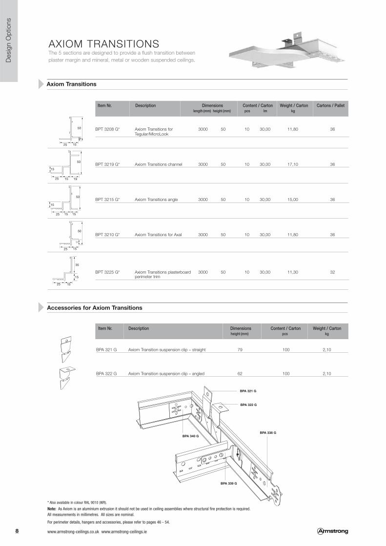
AXIOM TRANSITIONSThe 5 sections are designed to provide a flush transition betweenplaster margin and mineral, metal or wooden suspended ceilings.
BPT 3208 G* Axiom Transitions for 3000 50 10 30,00 11,80 36Tegular/MicroLook
BPT 3219 G* Axiom Transitions channel 3000 50 10 30,00 17,10 36
BPT 3215 G* Axiom Transitions angle 3000 50 10 30,00 15,00 36
BPT 3210 G* Axiom Transitions for Axal 3000 50 10 30,00 11,80 36
BPT 3225 G* Axiom Transitions plasterboard 3000 50 10 30,00 11,30 32perimeter trim
Item Nr. Description Dimensions Content / Carton Weight / Carton Cartons / Palletlength (mm) height (mm) pcs lm kg
Axiom Transitions
BPA 321 G Axiom Transition suspension clip – straight 79 100 2,10
BPA 322 G Axiom Transition suspension clip – angled 62 100 2,10
Item Nr. Description Dimensions Content / Carton Weight / Carton height (mm) pcs kg
25 15
11
50
25 15
8
50
25 19 15
15
50
25 15
15
35
25 15 15
15
50
* Also available in colour RAL 9010 (WR).
Note: As Axiom is an aluminium extrusion it should not be used in ceiling assemblies where structural fire protection is required.All measurements in millimetres. All sizes are nominal.
Accessories for Axiom Transitions
BPA 321 G
BPA 322 G
BPA 338 G
BPA 339 G
BPA 340 G
For perimeter details, hangers and accessories, please refer to pages 46 - 54.
8 www.armstrong-ceilings.co.uk www.armstrong-ceilings.ie

Des
ign
Opt
ions
AXIOM PROFILESAvailable in 5 heights with a plasterboard trim section, Axiom Profiles arecompatible with Trulok 24mm and 15mm grid systems including designer grid.
Item Nr. Description Dimensions Content / Carton Weight / Carton height (mm) pcs kg
* Also available in colour RAL 9010 (WR)
BP 52 42 06 G* Axiom Profile 50mm 3000 50 5 15,00 7,80 60BP 54 42 06 G* Axiom Profile 100mm 3000 100 5 15,00 11,20 36BP 56 42 06 G* Axiom Profile 150mm 3000 150 5 15,00 14,70 30BP 58 42 06 G* Axiom Profile 200mm 3000 200 5 15,00 17,80 24BP 55 14 11 G* Axiom Vector Profile 112mm 3000 112 5 15,00 12,25 15
BPT 3213 H* Profile plasterboard trim 3000 18,5 x 25,5 8 24,00 4,45 50
Item Nr. Description Dimensions Content / Carton Weight / Carton Cartons / Palletlength (mm) height (mm) pcs lm kg
Axiom Profiles
Accessories for Axiom Transitions and Profiles
Accessories for Axiom Profiles
BPA 334 G* Axiom Profile corner post 50 mm 50 2 0,25BPA 335 G* Axiom Profile corner post 100mm 100 2 0,50BPA 336 G* Axiom Profile corner post 150mm 150 2 0,70BPA 337 G* Axiom Profile corner post 200mm 200 2 0,95BPA 345 G* Axiom Vector corner post 112mm 112 2 0,56
BPA 340 G Axiom universal corner clip 100 2,10
BPA 338 G Axiom universal splice plate 100 2,10
BPA 339 G Axiom universal T-bar connector clip 100 2,10
BPA 344 G Axiom universal hanging clip 100 2,10
50
100
150
19
19
19
19
200
112
18.5
25.5
BPA 344 G
BPA 339 G
BPA 340 G
BPA 344 GBPA 334 GBPA 335 GBPA 336 GBPA 337 G BPA 345 G
BPA 338 G
9www.armstrong-ceilings.co.uk www.armstrong-ceilings.ie

Des
ign
Opt
ions
AXIOM CLASSIC CANOPYAxiom Classic Canopy is a perimeter trim system designed to create “ceiling clouds” inconjunction with full size tiles. Made from standard ceiling panels and ready to assembleAxiom components, Axiom Canopy will define and individualise any space.
BP 551411 G Axiom Vector MicroLook Tegular Profile
BPC 3000 G Primary C channel
BPA WDN 21 H Tee bar hanger
BPA 345 G Axiom Vector MicroLook Tegular Profile corner post
BPA 348 G Channel bracket
BPCA 97 G Clamp for C channel (not included in the kit)
BPA 347 G 24mm XL2 connector clip
BPA 346 G 15mm XL2 connector clip
BPA 339 G Universal T bar connector clip
Item Nr. Description
Axiom Classic Canopy Components
Axiom Classic Canopy Kits*
Module Grid system 15mm XL2 Grid system 24mm XL2
Item Nr. Item Nr.
1200 x 1200mm BP AX 22 G15 BP AX 22 G24
1800 x 1200mm BP AX 32 G15 BP AX 32 G24
1800 x 1800mm BP AX 33 G15 BP AX 33 G24
2400 x 1200mm BP AX 42 G15 BP AX 42 G24
2400 x 1800mm BP AX 43 G15 BP AX 43 G24
2400 x 2400mm BP AX 44 G15 BP AX 44 G24
3000 x 1200mm BP AX 52 G15 BP AX 52 G24
3000 x 1800mm BP AX 53 G15 BP AX 53 G24
3000 x 2400mm BP AX 54 G15 BP AX 54 G24
3000 x 3000mm BP AX 55 G15 BP AX 55 G24
* Ceiling tiles are NOT included in the kit.
1.2m
1.8m
2.4m
3.0m
2.4m 1.8m 1.2m 3.0m
4 tiles 6 tiles 8 tiles 10 tiles
15 tiles 12 tiles 9 tiles
20 tiles 16 tiles
25 tiles
112mm112mm
MicroLook TegularVector
R E C O M M E N D AT I O N S
Axiom Canopies should always be installed in accordance with allapplicable building codes and regulations.
• Axiom Canopies should only be installed on a horizontal plane. They are not approved for exterior installations.
• Axiom Canopies should always be installed by a minimum of 2 people.
• Read the installation instructions included in the carton carefully before starting the installation.
• Make sure the installation is clean and safe.
• Any additional weights (such as luminaires...) must be independently suspended from the soffit.
• Aircraft cables are included as a standard in the kit but if you require more lateral restraint, we would recommend the use of 6mm threaded rod or quick hangers.
!
All measurements in millimetres. All sizes are nominal.For perimeter details, hangers and accessories, please refer to pages 46 - 54.
10 www.armstrong-ceilings.co.uk www.armstrong-ceilings.ie
Des
ign
Opt
ions
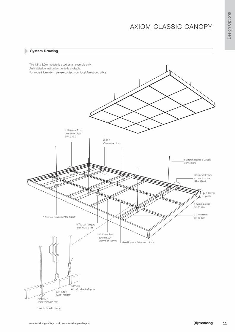
AXIOM CLASSIC CANOPY
System Drawing
6 Aircraft cables & Grippleconnectors
4 Cornerposts
4 Axiom profiles cut to size
3 C channels cut to size
2 Main Runners (24mm or 15mm)
12 Cross Tees 600mm XL2
(24mm or 15mm)
6 Tee bar hangers BPA WDN 21 H
6 Channel brackets BPA 348 G
4 Universal T barconnector clips BPA 339 G
8 XL2
Connector clips
6 Universal T barconnector clips BPA 339 G
OPTION 36mm Threaded rod*
* not included in the kit
OPTION 2Quick hanger*
OPTION 1Aircraft cable & Gripple
The 1.8 x 3.0m module is used as an example only.An installation instruction guide is available. For more information, please contact your local Armstrong office.
11www.armstrong-ceilings.co.uk www.armstrong-ceilings.ie

Axiom Canopy Components
Axiom Canopy Knife Edge Kits*
Item Nr. Description
BPCS 574206G Axiom Knife Edge Profile
BPC 3000 G Primary C channel
BPA WDN 21 H T bar hanger
BPCS 57 G Mitre corner piece
BPA 361 G Mitre corner splice connector
BPA 348 G Channel bracket
BPCA 97 G Clamp for C channel (not included in the kit)
BPA 347 G 24mm XL2 connector clip
BPA 346 G 15mm XL2 connector clip
BPA 339 G Universal T bar connector clip
BPA 338G Axiom universal splice plate
Module Grid system 15mm XL2 Grid system 24mm XL2
Item Nr. Item Nr.
1200 x 1200mm BPCS AK 22 G15 BPCS AK 22 G24
1800 x 1200mm BPCS AK 32 G15 BPCS AK 32 G24
1800 x 1800mm BPCS AK 33 G15 BPCS AK 33 G24
2400 x 1200mm BPCS AK 42 G15 BPCS AK 42 G24
2400 x 1800mm BPCS AK 43 G15 BPCS AK 43 G24
2400 x 2400mm BPCS AK 44 G15 BPCS AK 44 G24
3000 x 1200mm BPCS AK 52 G15 BPCS AK 52 G24
3000 x 1800mm BPCS AK 53 G15 BPCS AK 53 G24
3000 x 2400mm BPCS AK 54 G15 BPCS AK 54 G24
3000 x 3000mm BPCS AK 55 G15 BPCS AK 55 G24
*Ceiling tiles are NOT included in the kit.
1.2m
1.8m
2.4m
3.0m
2.4m 1.8m 1.2m 3.0m
4 tiles 6 tiles 8 tiles 10 tiles
15 tiles 12 tiles 9 tiles
20 tiles 16 tiles
25 tiles
AXIOM KNIFE EDGE CANOPYAxiom Knife Edge Canopy is an aesthetic perimeter trim system designed to create “ceiling clouds”in conjunction with full size tiles. Made from standard ceiling panels and ready to assemble Axiomcomponents, Axiom Knife Edge Canopy will define and individualise every space.
135mm
106mm
135mm
106mm
Vector
RECOMMENDATIONS
Axiom Knife Edge Canopies should always be installed inaccordance with all applicable building codes and regulations.
• Axiom Knife Edge Canopies should only be installed on a horizontal plane. They are not approved for exterior installations.
• Axiom Knife Edge Canopies should always be installed by a minimum of 2 people.
• Read the installation instructions included in the carton carefully before starting the installation.
• Make sure the installation is clean and safe.
• Any additional weights (such as luminaires...) must be independently suspended from the soffit.
!
Des
ign
Opt
ions
MicroLook Tegular
All measurements in millimetres. All sizes are nominal.For perimeter details, hangers and accessories, please refer to pages 46 - 54.
12 www.armstrong-ceilings.co.uk www.armstrong-ceilings.ie

System Drawing
4 Universal T barconnector clips BPA 339 G
6 Aircraft cables &Gripple connectors
6 Universal T barconnector clipsBPA 339 G
Corner spliceconnectors BPA 361G
4 Mitre Corners
4 Axiom profilescut to size
3 C channelscut to size2 Main Runners
(24mm or 15mm)
12 Cross Tees 600mm XL2
(24mm or 15mm)
6 T bar hangers BPA WDN 21 H
6 Channel bracketsBPA 348 G
16 Axiomuniversal spliceplates
8 XL2
Connector clips
AXIOM KNIFE EDGE CANOPY
The 1.8 x 3.0m module is used as an example only.An installation instruction guide is available. For more information, please contact your local Armstrong office.
Des
ign
Opt
ions
OPTION 36mm Threaded rod*
OPTION 2Quick hanger*
OPTION 1Aircraft cable & Gripple
* not included in the kit
13www.armstrong-ceilings.co.uk www.armstrong-ceilings.ie

Des
ign
Opt
ions
SILHOUETTE 15 XL2
Exposed 15 mm grid system (nominal).Silhouette XL2 is a suspension system designed to create a crisp, clean look inconjunction with MicroLook tiles to provide an enhanced aesthetic.
with 6mm revealBP 80 40 42 G 3600 44 20 72,00 24,50 36BP 80 48 42 G 3500 44 20 70,00 23,80 24BP 80 39 43 G 3125 44 20 62,50 25,40 25BP 80 44 42 G 2700 44 20 54,00 18,40 36
with 3mm revealBP 81 40 42 WRG* 3600 44 20 72,00 24,50 36
Item Nr. Dimensions Content / Carton Weight / Carton Cartons / Palletlength (mm) height (mm) pcs lm kg
Main Runners Silhouette 15 (by-pass connection)
Peakform Cross Tees Silhouette 15 XL2 (stab system)
Section Drawings
with 6mm revealBP 80 30 42 G 1200 44 60 72,00 24,50 35BP 80 31 43 G 1250 44 60 37,50 25,80 35BP 80 33 42 G 1350 44 30 40,50 13,80 50BP 80 32 42 G 1000 44 60 60,00 20,40 24
BP 80 20 42 G 600 44 60 36,00 12,70 70BP 80 21 43 G 625 44 30 37,50 16,00 70BP 80 23 42 G 675 44 60 40,50 14,30 70BP 80 22 42 G 500 44 60 30,00 10,60 70BP 80 24 42 G 300 44 120 36,00 34,00 70
with 3mm revealBP 81 30 42 WRG* 1200 44 60 72,00 24,50 35
BP 81 20 42 WRG* 600 44 60 36,00 12,70 70
Silhouette with 6mm reveal is available in white, black (BK) or white with black reveal (BI).* WR = White RAL 9010 (WR)
675 / 625 / 600 / 500 / 300
1350 675 675 1250 625 6251200 600 6001000 500 500
Main Runners Silhouette 15
Cross Tees Silhouette 15 XL2
Cross Tees Silhouette 15 XL2
3600 300 600 3 x 600 600 3003500 250 500 4 x 500 500 2503125 312,5 625 2 x 625 625 312,52700 337,5 675 675 675 337,5
Length
Length
All measurements in millimetres. All sizes are nominal.For perimeter details, hangers and accessories, please refer to pages 46 - 54.
14 www.armstrong-ceilings.co.uk www.armstrong-ceilings.ie
Des
ign
Opt
ions
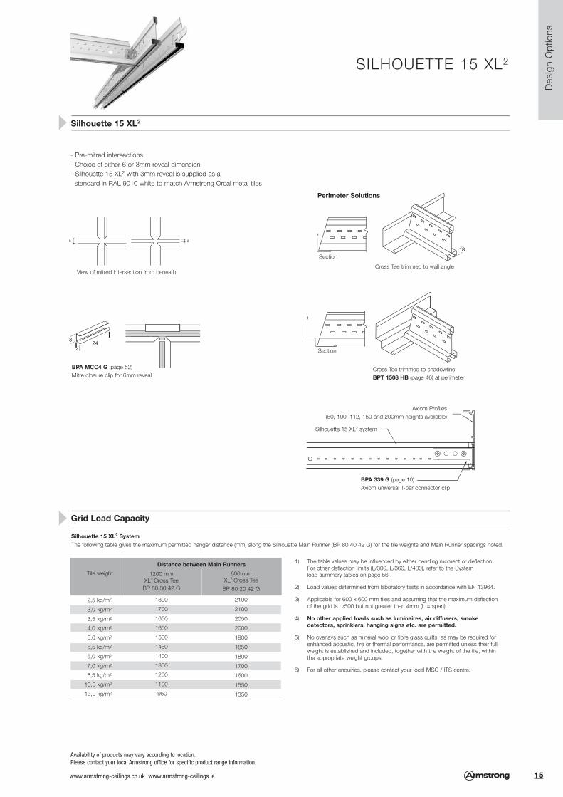
SILHOUETTE 15 XL2
Silhouette 15 XL2
- Pre-mitred intersections- Choice of either 6 or 3mm reveal dimension- Silhouette 15 XL2 with 3mm reveal is supplied as a
standard in RAL 9010 white to match Armstrong Orcal metal tiles
Grid Load Capacity
8
424
BPA MCC4 G (page 52)Mitre closure clip for 6mm reveal
View of mitred intersection from beneath
Section
Section
Axiom Profiles(50, 100, 112, 150 and 200mm heights available)
Silhouette 15 XL2 system
BPA 339 G (page 10)Axiom universal T-bar connector clip
Cross Tee trimmed to wall angle
Cross Tee trimmed to shadowline BPT 1508 HB (page 46) at perimeter
Availability of products may vary according to location.Please contact your local Armstrong office for specific product range information.
Perimeter Solutions
Silhouette 15 XL2 System The following table gives the maximum permitted hanger distance (mm) along the Silhouette Main Runner (BP 80 40 42 G) for the tile weights and Main Runner spacings noted.
Tile weight
2,5 kg/m2
3,0 kg/m2
3,5 kg/m2
4,0 kg/m2
5,0 kg/m2
5,5 kg/m2
6,0 kg/m2
7,0 kg/m2
8,5 kg/m2
10,5 kg/m2
13,0 kg/m2
1200 mm XL2 Cross Tee
BP 80 30 42 G
1800
1700
1650
1600
1500
1450
1400
1300
1200
1100
950
600 mm XL2 Cross Tee
BP 80 20 42 G
2100
2100
2050
2000
1900
1850
1800
1700
1600
1550
1350
1) The table values may be influenced by either bending moment or deflection.For other deflection limits (L/300, L/360, L/400), refer to the System load summary tables on page 56.
2) Load values determined from laboratory tests in accordance with EN 13964.
3) Applicable for 600 x 600 mm tiles and assuming that the maximum deflection of the grid is L/500 but not greater than 4mm (L = span).
4) No other applied loads such as luminaires, air diffusers, smoke detectors, sprinklers, hanging signs etc. are permitted.
5) No overlays such as mineral wool or fibre glass quilts, as may be required for enhanced acoustic, fire or thermal performance, are permitted unless their full weight is established and included, together with the weight of the tile, within the appropriate weight groups.
6) For all other enquiries, please contact your local MSC / ITS centre.
Distance between Main Runners
15www.armstrong-ceilings.co.uk www.armstrong-ceilings.ie

Des
ign
Opt
ions
INTERLUDE 15 XL2
Exposed 15 mm grid system (nominal).Interlude XL2 is a suspension system developed for creative ceilingsolutions, and quick and easy installation.
BP 61 40 42 G 3600 44 20 72,00 29,90 12
Item Nr. Dimensions Content / Carton Weight / Carton Cartons / Palletlength (mm) height (mm) pcs lm kg
Main Runner Interlude 15 (by-pass connection)
Cross Tees Interlude 15 XL2 (stab system)
Section Drawings
BP 61 30 42 G 1200 44 60 72,00 30,30 42
BP 61 20 42 G 600 44 60 36,00 15,00 84
BP 61 24 42 G 300 44 120 36,00 15,00 84
600 / 300
1200 600 600
3600 150 300 10 x 300 150
Main Runner Interlude 15
Cross Tee Interlude 15 XL2
Cross Tees Interlude 15 XL2
Length
Length
All measurements in millimetres. All sizes are nominal.For perimeter details, hangers and accessories, please refer to pages 46 - 54.
16 www.armstrong-ceilings.co.uk www.armstrong-ceilings.ie

Des
ign
Opt
ions
INTERLUDE 15 XL2
Availability of products may vary according to location.Please contact your local Armstrong office for specific product range information.
Interlude 15 XL2
Interlude 15 XL2 can be easily field cutwith snips in 3 simple steps:
- The stepped flange profile provides a unique double reveal visual- Unmitred intersections allow for Cross Tee installation at any
Main Runner slot position
Grid Load Capacities
Interlude XL2 15mm
The following table gives the maximum permitted hanger distance (mm) along the Interlude Main Runner (BP 61 40 42) for the tile weights and Main Runner spacings noted.
Tile weight
2,5 kg/m2
3,0 kg/m2
3,5 kg/m2
4,0 kg/m2
5,0 kg/m2
5,5 kg/m2
6,0 kg/m2
7,0 kg/m2
8,5 kg/m2
10,5 kg/m2
13,0 kg/m2
1200 mm XL2 Cross Tee
BP 61 30 42 G
1950
1850
1750
1750
1650
1600
1550
1450
1350
1250
1100
1) The table values may be influenced by either bending moment or deflection. For other deflection limits (L/300, L/360, L/400), refer to the System load summary tables on page 56.
2) Load values determined from laboratory tests in accordance with EN 13964.
3) Applicable for 600 x 600 mm tiles and assuming that the maximum deflection of the grid is L/500 but not greater than 4mm (L = span).
4) No other applied loads such as luminaires, air diffusers, smoke detectors, sprinklers, hanging signs etc. are permitted.
5) No overlays such as mineral wool or fibre glass quilts, as may be required for enhancedacoustic, fire or thermal performance, are permitted unless their full weight is established and included, together with the weight of the tile, within the appropriate weight groups.
6) For all other enquiries, please contact your local MSC / ITS centre.
Cross Tee trimmed to wall angle
Section
Section
Perimeter Solutions
Partition Head Fixing
Cross Tee trimmed to shadowlineBPT 1508 HB (page 46)
1. Cut down through bulb and web
2. Snip flanges
3. Bend away from bulb to snap off centre rail
BP UPC AG (page 54)Universal partition clipattaches to grid to provide fixingfor partition head track: reversible for15mm or 24mm gird
600 mm XL2 Cross Tee
BP 61 20 42 G
2100
2100
2100
2100
2050
2000
1950
1850
1750
1650
1550
Distance between Main Runners
17www.armstrong-ceilings.co.uk www.armstrong-ceilings.ie

Gen
eral
App
licat
ions
PRELUDE 15Exposed 15mm grid system (nominal).
BP 30 40 33 A 3600 43 20 72,00 22,50 32BP 30 41 33 A 3750 43 20 75,00 23,20 32BP 30 43 33 A 3375 43 20 67,50 21,20 32
Item Nr. Dimensions Content / Carton Weight / Carton Cartons / Palletlength (mm) height (mm) pcs lm kg
Universal Main Runners Prelude 15 Peakform and Superlock Clip (bulb-to-bulb connection)
Cross Tees Prelude 15 XL2 (stab system, override)
Cross Tees Prelude 15 TL (hook system, butt cut)
Section Drawings
Cross Tees slottedBP 30 30 33 B 1200 38 60 72,00 20,70 72BP 30 31 33 A 1250 38 60 75,00 21,55 72BP 30 32 33 * 1000 38 60 60,00 17,25 72
Cross Tees unslottedBP 30 20 33 B 600 38 60 36,00 10,30 144BP 30 21 33 A 625 38 60 37,50 10,70 144BP 30 22 33 * 500 38 60 30,00 8,60 144
Cross Tees slottedBP 10 34 33 A 1800 38 60 108,0 35,80 20 BP 10 36 33 A 1500 38 30 45,00 14,00 20 BP 10 33 33 1350 38 60 81,00 26,00 72 BP 10 31 33 B 1250 38 60 75,00 21,55 72 BP 10 30 33 A 1200 38 60 72,00 20,70 72
Cross Tees unslottedBP 10 23 33 675 38 60 40,50 13,00 144 BP 10 21 33 B 625 38 60 37,50 10,72 144 BP 10 20 33 A 600 38 60 36,00 10,29 144 BP 10 25 33 312,50 38 120 37,50 12,50 144 BP 10 24 33 A 300 38 120 36,00 11,50 144
3750 78,125 156,25 21 x 156,25 156,25 78,1253600 50 100 33 x 100 100 503375 337,5 675 2 x 675 675 337,5
1250 312,5 2 x 312,5 312,51200 300 2 x 300 3001000 250 2 x 250 250
625 / 600 / 500 675 / 625 / 600 / 312,5 / 300
Length
Length
1800 300 4 x 300 3001500 300 3 x 300 3001350 337,5 2 x 337,5 337,51250 312,5 2 x 312,5 312,51200 300 2 x 300 300
Length
Universal Main Runners Prelude 15
Cross Tees Prelude 15 XL2
Cross Tees Prelude 15 XL2
Cross Tees Prelude 15 TL
Cross Tees Prelude 15 TL
Colours available : Carrara (CA), Platinum (PN), Black (BK), RAL 9006 (SG), Brass (BS), Chrome (CE), White RAL 9010 (WR).* Also available in RAL 9010 (WR).Cross tee alignment is achieved by locating the tees to the right-hand side of the adjoining section.All measurements in millimetres. All sizes are nominal.For perimeter details, hangers and accessories, please refer to pages 46 - 54.
18 www.armstrong-ceilings.co.uk www.armstrong-ceilings.ie

Gen
eral
App
licat
ions
PRELUDE 15
System Drawing (module 600 x 600mm)
Standard lay-in installationof 15mm exposedsuspension system forBoard, or MicroLook tiles.
*reduce to 450 ifheavy tile / overlaysare used or heavyservice fittings arelocated near theperimeter.
Grid Load Capacities
Prelude 15mm Systems The following table gives the maximum permitted hanger distance (mm) along the Peakform Main Runner (BP 30 40 33 A) for the tile weights and Main Runner spacings noted.
Tile weight
2,5 kg/m2
3,0 kg/m2
3,5 kg/m2
4,0 kg/m2
5,0 kg/m2
5,5 kg/m2
6,0 kg/m2
7,0 kg/m2
8,5 kg/m2
10,5 kg/m2
13,0 kg/m2
1200 mm TL Cross Tee
BP 10 30 33 A
1900
1800
1750
1650
1550
1550
1500
1400
1300
1150
1050
600 mm TL Cross Tee
BP 10 20 33 A
2100
2100
2100
2050
2000
1950
1900
1800
1700
1600
1500
1200 mm XL2 Cross TeeBP 30 30 33 B
1900
1800
1750
1650
1550
1550
1500
1400
1300
1150
1050
600 mm XL2 Cross Tee BP 30 20 33 B
2100
2100
2100
2050
2000
1950
1900
1800
1700
1600
1500
1) The above table values may be influenced by either bending moment or deflection.For other deflection limits (L/300, L/360, L/400), refer to the System load summary tables on page 56.
2) Load values determined from laboratory tests in accordance with EN 13964.3) Applicable for 600 x 600 mm tiles and assuming that the maximum deflection of the grid is L/500 but not greater than 4mm (L = span).4) No other applied loads such as luminaires, air diffusers, smoke detectors, sprinklers, hanging signs etc. are permitted.5) No overlays such as mineral wool or fibre glass quilts, as may be required for enhanced acoustic, fire or thermal performance, are permitted unless their full weight is
established and included, together with the weight of the tile, within the appropriate weight groups.6) For all other enquiries, please contact your local MSC / ITS centre.
Availability of products may vary according to location.Please contact your local Armstrong office for specific product range information.
Tile Main Runner Hanger centres Main Runner Cross Tee Cross Tee Hanger Universal centres 1200mm 600mm retaining clip
600 x 600mm2,78 pcs
1200 x 600mm1,39 pcs
6 1 2 3 4 7
5 The chart is for general guidance only.
Quantities required per 1m2 (no waste included)
Perimeter trim approx. 0,70 lm/m2
1200mm
600mm
1200mm
600mm
1200mm
1200mm
1200mm
1200mm
0,84 lm
1,67 lm
0,84 lm
1,67 lm
1,67 lm
-
1,67 lm
-
0,84 lm
1,67 lm
-
0,84 lm
0,70 pcs
1,40 pcs
0,70 pcs
1,40 pcs
5,56 pcs
5,56 pcs
5,56 pcs
5,56 pcs
Distance between Main Runners
19www.armstrong-ceilings.co.uk www.armstrong-ceilings.ie

BP 31 40 32 A 3600 43 20 72,00 21,00 30BP 31 41 33 B 3750 43 20 75,00 22,00 30BP 31 43 33 A 3375 43 20 67,50 20,00 30BP 31 42 32 3000 43 20 60,00 17,50 30
Item Nr. Dimensions Content / Carton Weight / Carton Cartons / Palletlength (mm) height (mm) pcs lm kg
Universal Main Runners Prelude 24 Peakform and Superlock Clip (bulb-to-bulb connection)
Cross Tees Prelude 24 XL2 (stab system, override)
Section Drawings
Cross Tees Prelude 24 XL2
BP 31 30 51 B 1200 38 60 72,00 18,20 72BP 31 31 51 B 1250 38 60 75,00 19,00 72BP 31 32 31* 1000 38 60 60,00 15,10 42
BP 31 34 31 A 1800 38 30 54,00 17,00 20BP 31 24 51 G 300 35 120 36,00 9,20 96BP 31 25 51 G 312,50 35 120 37,50 9,60 96
BP 31 20 21 A 600 30 60 36,00 8,20 144BP 31 21 23 A 625 30 60 37,50 8,60 144BP 31 22 21 * 500 30 60 30,00 6,80 84
3750 78,125 156,25 21 x 156,25 156,25 78,1253600 50 100 33 x 100 100 503375 337,5 675 2 x 675 675 337,53000 50 100 27 x 100 100 50
1800 300 4 x 300 3001250 312,5 2 x 312,5 312,51200 300 2 x 300 3001000 250 2 x 250 250
625 / 600 / 500 / 312,50 / 300
Cross Tees Prelude 24 XL2
Length
Length
Universal Main Runners Prelude 24
Colours available : Carrara (CA), Platinum (PN), Black (BK), RAL 9006 (SG), Chrome (CE), White RAL 9010 (WR).* Also available in RAL 9010 (WR).Cross tee alignment is achieved by locating the tees to the right-hand side of the adjoining section.All measurements in millimetres. All sizes are nominal.
PRELUDE 24 XL2
Exposed 24 mm grid system (nominal).
Gen
eral
App
licat
ions
For perimeter details, hangers and accessories, please refer to pages 46 - 54.
Cross Tees slotted
Cross Tees unslotted
20 www.armstrong-ceilings.co.uk www.armstrong-ceilings.ie

Gen
eral
App
licat
ions
Tile Main Runner Hangers Main Runner Cross Tee Cross Tee Hanger Universal centres centres 1200mm 600mm retaining clip
1200 x 600mm 1,39 pcs
600 x 600mm2,78 pcs
PRELUDE 24 XL2
System Drawing (module 1200 x 600mm)
6 1 2 3 4 7
5
Standard lay-in installation of 24mm exposed suspension systemusing Board or Tegular tiles.(See page 29 for 600 x 600mm module)
Grid Load Capacities
Prelude 24 XL2 System The following table gives the maximum permitted hanger distance (mm) along the Peakform Main Runner (BP 31 40 32 A) for the tile weights and Main Runner spacings noted.
Tile weight
2,5 kg/m2
3,0 kg/m2
3,5 kg/m2
4,0 kg/m2
5,0 kg/m2
5,5 kg/m2
6,0 kg/m2
7,0 kg/m2
8,5 kg/m2
10,5 kg/m2
13,0 kg/m2
1800 mm XL2 Cross Tee BP 31 34 31 A
1650
1600
1500
1450
1350
1350
1250
-
-
-
-
1200 mm XL2 Cross Tee BP 31 30 51 B
1900
1800
1750
1700
1600
1550
1500
1450
1300
1200
1050
600 mm XL2 Cross Tee BP 31 20 21 A
2100
2100
2100
2100
2000
1950
1900
1800
1700
1600
1500
1) The above table values may be influenced by either bending moment or deflection.For other deflection limits (L/300, L/360, L/400), refer to the System load summary tables on page 56.
2) Load values determined from laboratory tests in accordance with EN 13964.3) Applicable for 600 x 600 mm tiles and assuming that the maximum deflection of the grid is L/500 but not greater than 4mm (L = span).4) No other applied loads such as luminaires, air diffusers, smoke detectors, sprinklers, hanging signs etc. are permitted.5) No overlays such as mineral wool or fibre glass quilts, as may be required for enhanced acoustic, fire or thermal performance, are permitted
unless their full weight is established and included, together with the weight of the tile, within the appropriate weight groups.6) For all other enquiries, please contact your local MSC / ITS centre.
Availability of products may vary according to location.Please contact your local Armstrong office for specific product range information.
The chart is for general guidance only.
Quantities required per 1m2 (no waste included)
Perimeter trim approx. 0,70 lm/m2
1200mm
600mm
1200mm
600mm
1200mm
1200mm
1200mm
1200mm
0,84 lm
1,67 lm
0,84 lm
1,67 lm
1,67 lm
-
1,67 lm
-
-
0,84 lm
0,84 lm
1,67 lm
0,70 pcs
1,40 pcs
0,70 pcs
1,40 pcs
5,56 pcs
5,56 pcs
5,56 pcs
5,56 pcs
Distance between Main Runners
*reduce to 450 ifheavy tile / overlaysare used or heavyservice fittings arelocated near theperimeter.
21www.armstrong-ceilings.co.uk www.armstrong-ceilings.ie

PRELUDE 24 TLXExposed 24 mm grid system (nominal).
Gen
eral
App
licat
ions
Item Nr. Dimensions Content / Carton Weight/ctn Ctns/palletLength (mm) Height (mm) pcs lm kg
Cross Tees Prelude 24 TLX (Hook system, butt cut)
Universal Main Runners Prelude 24 Peakform and Superlock Clip (bulb-to-bulb connection)
625/600/500/675/900
Cross Tees Prelude 24 TLX
Section Drawings
BP 31 40 32 A 3600 43 20 72,00 21,00 30BP 31 41 33 B 3750 43 20 75,00 22,00 30BP 31 43 33 A 3375 43 20 67,50 20,00 30BP 31 42 32 3000 43 20 60,00 17,50 30
Cross Tees slottedBP 13 33 32 1350 38 60 81,00 24,90 20 BP 13 31 31 1250 38 60 75,00 18,91 72 BP 13 30 31* 1200 38 60 72,00 18,15 72 BP 13 32 32 1000 38 60 60,00 19,40 72 BP 13 60 31 600 38 60 36,00 9,08 144
BP 13 10 32 1875 38 30 56,25 17,84 20 BP 13 34 32 1800 38 30 54,00 17,13 20 BP 13 50 32 1724 38 30 51,72 16,46 20 BP 13 36 32 1500 38 30 45,00 14,50 20 BP 13 30 21 1200 30 60 72,00 16,40 72
Cross Tees unslottedBP 13 18 31 900 38 60 54,00 13,61 72 BP 13 23 32 675 38 60 40,50 13,10 144 BP 13 21 31 625 38 60 37,50 9,46 144 BP 13 20 31* 600 38 60 36,00 9,08 144 BP 13 22 32 500 38 60 30,00 9,70 80
BP 13 21 21 625 30 60 37,50 8,55 144BP 13 20 21 600 30 60 36,00 8,20 144
3750 78,125 156,25 21 x 156,25 156,25 78,1253600 50 100 33 x 100 100 503375 337,5 675 2 x 675 675 337,53000 50 100 27 x 100 100 50
Length
Universal Main Runners Prelude 24
Cross Tees Prelude 24 TLX
1875 625 1 x 625 3001724 262 4 x 300 312,51500 150 350 2 x 250 1501350 337,5 2 x 337,5 337,51800 300 4 x 300 3001250 312,5 2 x 312,5 312,51200 300 2 x 300 3001000 250 2 x 250 250
Length
For perimeter details, hangers and accessories, please refer to pages 46 - 54.
Colours available : Carrara (CA), Platinum (PN), Black (BK), RAL 9006 (SG), Chrome (CE), White RAL 9010 (WR), Brass (BS).* Also available in Black (NG), Brown (MR), Beige (BJ), SG (RAL9006).Cross tee alignment is achieved by locating the tees to the right-hand side of the adjoining section.All measurements in millimetres. All sizes are nominal.
22 www.armstrong-ceilings.co.uk www.armstrong-ceilings.ie

Gen
eral
App
licat
ions
Tile Main Runner Hanger Main Runner Cross Tee Cross Tee Hanger Universal centres centres 1200mm 600mm Retaining Clip
1200 x 600mm 1,39 pcs
600 x 600mm2,78 pcs
System Drawing (module 1200 x 600mm)
6 1 2 3 4 7
5
Standard lay-in installation of24mm exposed suspension system using Board or Tegular edge tiles.
The chart is for general guidance only.
Quantities required per 1m2 (no waste included)
Perimeter Trim approx. 0,70 lm/m2
1200mm
600mm
1200mm
600mm
1200mm
1200mm
1200mm
1200mm
0,84 lm
1,67 lm
0,84 lm
1,67 lm
1,67 lm
-
1,67 lm
-
-
0,84 lm
0,84 lm
1,67 lm
0,70 pcs
1,40 pcs
0,70 pcs
1,40 pcs
5,56 pcs
5,56 pcs
5,56 pcs
5,56 pcs
PRELUDE 24 TLX
Grid Load Capacities
Prelude 24 TLX System The following table gives the maximum permitted hanger distance (mm) along the Peakform Main Runner(BP 31 40 32 A) for the tile weights and Main Runner spacings noted.
Tile weight
2,5 kg/m2
3,0 kg/m2
3,5 kg/m2
4,0 kg/m2
5,0 kg/m2
5,5 kg/m2
6,0 kg/m2
7,0 kg/m2
8,5 kg/m2
10,5 kg/m2
13,0 kg/m2
1800 mm TLX Cross Tee BP 13 34 32
1650
1600
1500
1450
1350
1350
1250
-
-
-
-
1200 mm TLX Cross Tee BP 13 30 31
1900
1800
1750
1700
1600
1550
1500
1450
1300
1200
1050
600mm TLX Cross Tee BP 13 20 31
2100
2100
2100
2100
2000
1950
1900
1800
1700
1600
1500
1) The above table values may be influenced by either bending moment or deflection.For other deflection limits (L/300, L/360, L/400), refer to the System load summary tables on page 56.
2) Load values determined from laboratory tests in accordance with EN 13964.3) Applicable for 600 x 600 mm tiles and assuming that the maximum deflection of the grid is L/500 but not greater than 4mm (L = span).4) No other applied loads such as luminaires, air diffusers, smoke detectors, sprinklers, hanging signs etc. are permitted.5) No overlays such as mineral wool or fibre glass quilts, as may be required for enhanced acoustic, fire or thermal performance, are permitted unless their full weight is
established and included, together with the weight of the tile, within the appropriate weight groups.6) For all other enquiries, please contact your local MSC / ITS centre.
Availability of products may vary according to location.Please contact your local Armstrong office for specific product range information.
Distance between Main Runners
*reduce to 450 if heavy tile / overlays are used orheavy service fittings arelocated near the perimeter.
23www.armstrong-ceilings.co.uk www.armstrong-ceilings.ie

PRELUDE SIXTY2
Exposed 24 mm grid system.Double Peakform Main Runner section requiring less suspension points andcompatible with Prelude 24 XL2 and TLX Cross Tees.G
ener
al A
pplic
atio
ns
Universal Main Runner Prelude Sixty2 Double Peakform with Superlock Clip (bulb to bulb connection)
3750 156,25 11 x 312,5 156,253600 150 11 x 300 1503375 168.75 9 x 337.5 168.75
Length
Universal Main Runner Prelude Sixty2
BP 40 40 93 G 3600 62 12 43,20 21.90 36
BP 40 41 93 G 3750 62 12 45,00 22.80 36
BP 40 43 93 G 3375 62 12 40,50 20.60 36
Cross Tees Prelude 24 TLX (hook system, butt cut)
Cross Tees slottedBP 13 33 32 1350 38 60 81,00 24,90 20 BP 13 31 31 1250 38 60 75,00 18,91 72 BP 13 30 31* 1200 38 60 72,00 18,15 72 BP 13 60 31 600 38 60 36,00 9,08 144
BP 13 10 32 1875 38 30 56,25 17,84 20 BP 13 34 32 1800 38 30 54,00 17,13 20
Cross Tees unslottedBP 13 23 32 675 38 60 40,50 13,10 144 BP 13 21 31 625 38 60 37,50 9,46 144 BP 13 20 31** 600 38 60 36,00 9,08 144
BP 13 21 21 625 30 60 37,50 8,55 144BP 13 20 21 600 30 60 36,00 8,20 144
Cross Tees Prelude 24 XL2 (stab system, override)
Cross Tees slottedBP 31 30 51 B 1200 38 60 72,00 18,20 72BP 31 31 51 B 1250 38 60 75,00 19,00 72
BP 31 34 31 A 1800 38 30 54,00 17,00 20
Cross Tees unslottedBP 31 20 21 A 600 30 60 36,00 8,20 144BP 31 21 23 A 625 30 60 37,50 8,60 144
Item Nr. Dimensions Content / Carton Weight/ctn Ctns/palletLength (mm) Height (mm) pcs lm kg
* Also available in RAL 9010 (WR)** Also available in Black (NG), Brown (MR), Beige (BJ), SG (RAL9006).
Colours available: Carrara (CA), Platinum (PN), Black (BK), RAL 9006 (SG), Chrome (CE), White RAL 9010 (WR), Brass (BS).All measurements in millimetres. All sizes are nominal.
24 www.armstrong-ceilings.co.uk www.armstrong-ceilings.ie

PRELUDE SIXTY2
Gen
eral
App
licat
ions
Availability of products may vary according to location.Please contact your local Armstrong office for specific product range information.
Accessories
Item Nr. Description Dimensions Content/ctn Weight/Ctn Length (mm) Height (mm) pcs (kg)
BP A401 G Top Connector Clip accessory for 57 34 12 0.3Prelude Sixty2 (Included in the kit)
BPA WDN23 G Double bent tee bar hanger 57 36 100 2.26
Tile Main Runner centres Main Runner Cross Tee 1800mm Cross Tee 1200mm Cross Tee 600mm
System Drawing (module 1800 x 300mm)
3 1 2 2 2
The chart is for general guidance only.
Quantities required per 1m2 (no waste included)
1800 x 300
600 x 600
600 x 600
600 x 600
1200 x 600
1200 x 600
1800mm
1800mm
1200mm
600mm
1200mm
600mm
0,56 lm
0,56 lm
0,84 lm
1,67 lm
0,84 lm
1,67 lm
3,34 lm
1,67 lm
-
-
-
-
-
-
1,67 lm
-
1,67 lm
-
-
1,12 lm
0,84 lm
1,67 lm
-
0,84 lm
Grid Load Capacities
Prelude Sixty2 System
Tile weight
2,5 kg/m2
3,0 kg/m2
3,5 kg/m2
4,0 kg/m2
5,0 kg/m2
5,5 kg/m2
6,0 kg/m2
7,0 kg/m2
8,5 kg/m2
10,5 kg/m2
13,0 kg/m2
1800mm Cross TeesBP133432/BP313431A
2300
2200
2150
2100
2000
1900
1850
-
-
-
-
1200mm Cross TeesBP133031/BP313051B
2400
2400
2350
2300
2200
2150
2100
2050
1900
1700
1550
600mm Cross Tees BP132031/BP312021A
2400
2400
2400
2400
2400
2400
2400
2400
2300
2200
2100
The following table gives the maximum permitted hanger distance (mm)along the Prelude Sixty2 Peakform Main Runner (BP 40 40 93 G) for thetile weights and Main Runner spacings noted.
1) The table values may be influenced by either bending moment or deflection.For other deflection limits (L/300, L/360, L/400), refer to the System load summary tables on page 56.
2) Load values determined from laboratory tests in accordance with EN 13964.
3) Applicable for 600 x 600 mm tiles and assuming that the maximum deflection of the grid is L/500 but not greater than 4mm (L = span).
4) No other applied loads such as luminaires, air diffusers, smokedetectors, sprinklers, hanging signs etc. are permitted.
5) No overlays such as mineral wool or fibre glass quilts, as may be required for enhanced acoustic, fire or thermal performance, are permitted unless their full weight is established and included, togetherwith the weight of the tile, within the appropriate weight groups.
6) For all other enquiries, please contact your local MSC / ITS centre.
Distance between Main Runners
Standard lay-in installation of24mm exposed suspensionsystem using Board orTegular edge planks.
25www.armstrong-ceilings.co.uk www.armstrong-ceilings.ie

White cappingBP 12 40 33 A 3600 38 18 64,80 26,10 28BP 12 45 33 A 3520 38 18 63,36 25,50 28
Galvanised cappingBP 12 40 33 UP 3600 38 18 64,80 26,10 28BP 12 45 33 UP 3520 38 18 63,36 25,50 28
Knurled - plasterboard optionBP 12 40 33 KD 3600 38 18 64,80 26,10 28BP 12 45 33 KD 3520 38 18 63,36 25,50 28
Item Nr. Dimensions Content / Carton Weight / Carton Cartons / Palletlength (mm) height (mm) pcs lm kg
PRELUDE 35Exposed 35 mm grid system (nominal).The Prelude 35 system is available with white and galvanised capping aswell as in a knurled version recommended for dry wall assemblies.
Main Runners Prelude 35 (bulb-to-bulb connection)
Cross Tees Prelude 35 TL (hook system with override)
Section Drawings
White cappingBP 12 36 33 A 1500 38 40 60,00 24,50 66BP 12 30 33 A 1200 38 50 60,00 24,50 55
Galvanised cappingBP 12 36 33 UP 1500 38 40 60,00 24,50 66BP 12 30 33 UP 1200 38 50 60,00 24,50 55
Knurled - plasterboard optionBP 12 36 33 KD 1500 38 40 60,00 25,80 66BP 12 30 33 KD 1200 38 50 60,00 25,80 55
38mm
35mm
38mm
35mm
3600 50 100 33 x 100 100 503520 110 220 13 x 220 220 110
Length
1500 750 7501200 600 600
Length
Main Runners Prelude 35
Cross Tees Prelude 35 TL
Note : The following cross tee lengths are available on request : 1800, 1320, 900, 750, 660 and 600mmCross Tee alignment is achieved by locating the tees to the left-hand side of the adjoining section.All measurements in millimetres. All sizes are nominal.
Gen
eral
App
licat
ions
For perimeter details, hangers and accessories, please refer to pages 46 - 54.
26 www.armstrong-ceilings.co.uk www.armstrong-ceilings.ie

PRELUDE 35
Gen
eral
App
licat
ions
Availability of products may vary according to location.Please contact your local Armstrong office for specific product range information.
System Drawing (module 1200 x 600mm)
Standard lay-in installation of 35mmexposed suspension system usingBoard or Tegular tiles.
Grid Load Capacities
Prelude 35 System
The following table gives the maximum permitted hanger distance (mm) along the T35 Main Runner (BP12 40 33 A) for the tile weights and Main Runner spacings noted.
1) The table values may be influenced by either bending moment or deflection.For other deflection limits (L/300, L/360, L/400), refer to the System load summary tables on page 56.
2) Load values determined from laboratory tests in accordance with EN 13964.
3) Applicable for 600 x 600 mm tiles and assuming that the maximum deflection of the grid is L/500 but not greater than 4mm (L = span).
4) No other applied loads such as luminaires, air diffusers, smoke detectors, sprinklers, hanging signs etc. are permitted.
5) No overlays such as mineral wool or fibre glass quilts, as may be required for enhanced acoustic, fire or thermal performance, are permitted unless their full weight is established and included, together with the weight of the tile, within the appropriate weight groups.
6) For all other enquiries, please contact your local MSC / ITS centre.
Tile Main Runner Hanger centres Main Runner Cross Tee Cross Tee Hanger Retaining clipcentres at at 1200mm 600mm
1200 x 600mm 1,39 pcs
6 1 2 3 4 7
5 The chart is for general guidance only.
Quantities required per 1m2 (no waste included)
Perimeter trim approx. 0,70 lm/m2
1200mm 1200mm 0,84 lm 1,67 lm - 0,7 pcs 5,56 pcs
Tile weight 1200 mm Cross Tee 600 mm Cross Tee BP 12 30 33 A BP 12 20 33
2,5 kg/m2
3,0 kg/m2
3,5 kg/m2
4,0 kg/m2
5,0 kg/m2
5,5 kg/m2
6,0 kg/m2
7,0 kg/m2
8,5 kg/m2
10,5 kg/m2
13,0 kg/m2
1800
1750
1700
1600
1550
1500
1450
1350
1200
1150
1000
2100
2100
2100
2050
1950
1900
1850
1750
1650
1600
1400
Distance between Main Runners
27www.armstrong-ceilings.co.uk www.armstrong-ceilings.ie

Gen
eral
App
licat
ions
BANDRASTERBandraster profiles.Bandraster is a suspension system available in a wide range of widths,compatible with Prelude 24 TLX/XL2 Cross Tees.
Slotted (1) at 300 mmBP 36 1050 A 3600 50 8 28,80 24,00 28BP 36 1075 A 3600 75 8 28,80 27,70 20BP 36 1125 A 3600 125 8 28,80 38,30 12BP 36 1150 3600 150 4 14,40 21,20 20
Slotted (1) at 312,50 mmBP 36 2100 B 3750 100 8 30,00 32,60 16
Slotted (1) at 100 mmBP 36 3050 3600 50 8 28,80 24,00 28BP 36 3075 3600 75 8 28,80 27,70 20BP 36 3100 * 3600 100 8 28,80 31,40 16BP 36 3125 3600 125 8 28,80 38,30 12BP 36 3150 3600 150 4 14,40 21,20 20
Unslotted (2) BP 36 0050 A 3600 50 8 28,80 24,00 28BP 36 0075 A 3600 75 8 28,80 27,70 20BP 36 0100 A 3600 100 8 28,80 31,40 16BP 36 0125 A 3600 125 8 28,80 38,30 12BP 36 0150 3600 150 4 14,40 21,20 20
(1) Is compatible with all edge details, even including Orcal planks (SE, TE8, TE16, TE30) and SL2 planks, but the slots are not required for the Orcal and SL2 planks.
(2) Is only compatible with Orcal planks (SE, TE8, TE16, TE30) and SL2 planks (i.e. not Tegular or MicroLook planks).
BPA 36 0501 Strip / rod connector 50 50 1,20BPA 36 0751 75 50 1,50BPA 36 1001 100 50 1,80
BPA 36 0502 G Nonius hanger 50 100 5,80BPA 36 0752 G 75 100 8,10BPA 36 1002 G 100 100 11,00BPA 36 1252 G 125 100 12,50BPA 36 1502 G 150 100 12,50
BPA 36 0503 G Splice 50 100 8,00BPA 36 0753 G 75 100 8,30BPA 36 1003 G 100 100 14,00BPA 36 1253 G 125 100 17,00BPA 36 1503 G 150 100 19,50
BPA 36 0504 G Cross connector 50 100 5,80BPA 36 0754 G 75 100 8,10BPA 36 1004 G 100 100 11,00BPA 36 1254 G 125 100 12,50BPA 36 1504 G 150 50 7,50
BPA 36 0505 G Wall connector 50 100 5,80BPA 36 0755 G 75 100 8,10BPA 36 1005 G 100 100 11,00BPA 36 1255 G 125 100 12,50BPA 36 1505 G 150 50 7,50
BPA 36 0506 G Crossing element 50 48 7,70BPA 36 0756 G 75 30 5,70BPA 36 1006 G 100 32 7,70
Item Nr. Dimensions Content / Carton Weight / Carton Cartons / Palletlength (mm) width (mm) pcs lm kg
Bandraster Sections
Bandraster Accessories
Item Nr. Description Dimension Carton / content Carton / weight width (mm) pcs kg
* Also available in RAL 9010 (WR)
36mm
12mm12mm
150 / 125 / 100 / 75 / 50mm150 / 125 / 100 / 75 / 50mm
All measurements in millimetres. All sizes are nominal.For perimeter details, hangers and accessories, please refer to pages 46 - 54.
28 www.armstrong-ceilings.co.uk www.armstrong-ceilings.ie

Gen
eral
App
licat
ions
BANDRASTER
Availability of products may vary according to location.Please contact your local Armstrong office for specific product range information.
Pin to connect bottom and upper part ofNonius (BPA 10229 G - page 50)(It is recommended to use 2 pins toconnect bottom & upper part of Nonius)
Upper part of Nonius(BPA 10202 H - page 50)
Splice
Crossing element
Threaded rod(BPA 1829 G page 49)
Wall connector
Nonius hanger
Strip / rod connector
Crossconnector
- Slotted Bandraster is compatible either with Prelude 24 XL2 or Prelude 24 TLX Cross Tees - On special request: Prelude 15 TL can be made compatible for
installation with slotted Bandraster;- Special spaced slotting; minimum slot spacing is 50mm;
Maximum length of Bandraster is 6000mm
System Drawing
29www.armstrong-ceilings.co.uk www.armstrong-ceilings.ie

Gen
eral
App
licat
ions
BP CZ 41494 H Deep Z 32mm 1500 20 30,00 9,40BP CZ 41794 H Deep Z 32mm 1800 20 36,00 11,30BP CZ 41795 H Deep Z 70mm 2500 10 25,00 13,40
BP CA5740 G Double height Z 4000 10 40,00 24,00
BP CA 5733 A Spacer bar 600/625 50 31,25 7,00
BP CA 5734 Spacer bar 1200/1250 50 62,50 14,00
BP CZ 3600 H Z section 3600 20 72,00 22,70
BP CA 21 G Z connector 150 500 - 10,00
BP CC 4000 G Channel 13 x 38mm 4000 20 80,00 26,50BP C 3000 G Channel 19 x 38mm 4000 8 32,00 23,80
BP CA 120 G Preformed channel clip - 100 - 0,50
Item Nr. Description Dimensions Carton / Content Carton / Weightlength (mm) pcs lm kg
SYSTEM ZSemi-concealed and concealed systems.Provides specialist solution for corridors giving a monolithic visual. Can also beused for room situations in conjunction with Prelude 24 and Bandraster grid.
BP CC 4000 G
BP CA 120 G
Semi-Concealed - Compatible with SL2 and K2C2
BP CZ 3600 H
BP CA 21 G
Semi-Concealed - Compatible with K4C4
All measurements in millimetres. All sizes are nominal.For perimeter details, hangers and accessories, please refer to pages 46 - 54.
30 www.armstrong-ceilings.co.uk www.armstrong-ceilings.ie

Gen
eral
App
licat
ions
BP CA 97 G Clamp for C-channel - 100 - 1,70
BP CT600 G Noggin tee 600 100 - 8,50
BP CA 5730 G Anti-breather spline - 200 - 3,85
SYSTEM Z
BP CC 4000 G
Item Nr. Description Dimensions Carton / Content Carton / Weightlength (mm) pcs lm kg
Semi-Concealed - Compatible with K4C4 (continued)
Availability of products may vary according to location.Please contact your local Armstrong office for specific product range information.
System Drawing
SL2
K2C2
Quantities required per 1m2 (no waste included)
13
2
The chart is for general guidance only.
Plank size
1500 x 300 / 312,5mm1800 x 300 / 312,5mm2000 x 300 / 312,5mm2500 x 300 / 312,5mm
Supportingsections
at
300 / 312,5mm300 / 312,5mm300 / 312,5mm300 / 312,5mm
Z ProfileBP CZ 41494 H
3,33 / 3,20 lm---
Z ProfileBP CZ 41794 H
-3,33/3,20 lm
--
Z Profile BP CZ 41795 H
--
3,33 / 3,20 lm3,33 / 3,20 lm
Perimeter trim according to circumference of room (as a basis 1,0 lm/m2 )Perimeter angles should be of thicker material when corridor wider than 1,80
Semi-concealed SL2/K2C2Corridor installation
31www.armstrong-ceilings.co.uk www.armstrong-ceilings.ie

Gen
eral
App
licat
ions
DRYWALL GRID SYSTEMThe Drywall Grid System (DGS) is a quick and easy to install suspension system for plasterboard ceilings, available in a range of two unique systems : Standard for typical flat installations and Faceted for curved and domed ceilings.
Peakform Main Runner and Superlock Clip (bulb to bulb connection)
Accessories
Item Nr. Dimensions Content / Carton Weight / Carton Cartons / Palletlength (mm) height (mm) width (mm) pcs Im kg
Main Runners BP 7940 G slot at 150mm 3600 38 38 12 43,20 20 36BP 7942 G slot at 150mm 3000 38 38 12 36,00 17 36 BP 7941 G slot at 100mm 3600 38 38 12 43,20 19,52 36
Faceted Main Runners BP HD 8906 F08 G 3658 43 38 12 43,92 22 24BP HD 8906 F16 G 3658 43 38 12 43,92 22 24
Cross TeesBP 7930 G 1200 38 38 36 43,20 20 48BP 7918 900 38 38 36 33,00 15 48BP 7920 G 600 38 38 36 21,60 10 96
Unhemmed C channelBP 7838 G 3048 (120") 40 20 60.96 16 32
Knurled angle trimBP KAM 12 H 3658 (12') 32 32 30 109.72 26 12
19
43
A variety of Drywall Grid accessories are available to provide problem solving solutions that save time, labour and money.
Item Nr. ImageItem Nr. Image Item Nr. Image
BP DWACS AGDrywall attachment clip
BP DW30C AG BP DW45C AG BP DW60C AG BP DW90C AGDrywall angle clips
BP RC2 AG Radius clip
BP MBAC AG Main Runner adapter clip
BP DW50 AGTransition clip for 1/2" drywall
BP DW58 AG Transition clip for 5/8" drywall
BP MBSC2 AGMain Runner spacer clip
BP XTAC AG Cross Tee adapter clip
BP DLCC AG Direct load ceiling clip
BP DWC AGDrywall clip
All measurements in millimetres. All sizes are nominal.For perimeter details, hangers and accessories, please refer to pages 46 - 54.
32 www.armstrong-ceilings.co.uk www.armstrong-ceilings.ie

Gen
eral
App
licat
ions
DRYWALL GRID SYSTEM
Section Drawings
For more information, please ask for the Drywall Gird System Curved and Flat brochure.
Faceted Main Runners faceted at 203mm (8") centres. Use for radius 4.50m or less
Faceted at 406mm (16") centres. Use for radius over 4.50m (directional Main Runner)
Cross Tees
Length
BP 7940 G 3600mmBP 7941 G 3600mmBP 7942 G 3000mm
BP HD 8906 F08 G
BP HD 8906 F16 G
BP 7930 G
BP 7920 G BP 7918 G
(45 slots) 3658mm
1200mm
600mm900mm
(54 slots) 3658mm
Hanger wire or suspension angleVertical brace
Main Runner
Cross Tee
System Drawing
Main Runner
33www.armstrong-ceilings.co.uk www.armstrong-ceilings.ie

Lockingtab
The gap between walltrim and shortspanshould not be over 3mm
BP LAT 12/10 Hmust be screwedto wall structure
Alignmentcrimps
Locking tabsat 150/100mmcentres.
150/100mm
Cor
ridor
DRYWALL GRID SYSTEM SHORTSPANThe Drywall Grid System (DGS) ShortSpan is a quick and easy to install suspensionsystem for plasterboard ceilings and in particular for corridors in both commercialand residential installations.
Drywall Grid System (DGS) Shortspan product range
BPS 7708 G 2438 (8') 38 12 29,26 13 24BPS 7710 G 3048 (10') 38 12 36,57 17 24BPS 7712 G 3658 (12') 38 12 43,89 20 24BPS 7714 G 4267 (14') 38 12 51,20 23 24
BP LAT 12 H 3600 32 30 109,72 18 12
BP LAT 10 H 3600 30 30 110,00 15 12
BP KAM 12 H 3658 (12') 32 30 109.72 26 12
Item Nr. Dimensions Content / Carton Weight / Bundle Bundles / Palletlength(mm) height (mm) pcs Im kg
Shortspan T-bars
Locking angle trimsLocking tabs at 150mm for the BP LAT 12HLocking tabs at 100mm for the BP LAT 10H
Knurled angle trim
The ShortSpan system is designed for use in drywall ceilings where the spans do not exceed 4200mm. The individual ShortSpan tees are not designed to be used independent of the locking angle trim (BP LAT 12 H) or optional knurled angle trim (BP KAM 12 H).
System Drawing
For more information, please ask for the Drywall Grid System Standard and Faceted brochure.All measurements in millimetres. All sizes are nominal.For perimeter details, hangers and accessories, please refer to pages 46 - 54.
34 www.armstrong-ceilings.co.uk www.armstrong-ceilings.ie

Planks
Perimeter trim
Double bent teebar hanger
Cor
ridor
PRELUDE SIXTY2Exposed 24 mm grid system.
Double Peakform Main Runner section requiring less suspension points and compatible with Prelude 24 XL2 and TLX Cross Tees.
The Prelude Sixty2 system is designed for use in corridor applications, with or without Cross Tees, andwhere spans do not exceed 3750mm. For a wider configuration, the Main Runner is compatible with thePrelude 24 TLX and XL2 Cross Tees. (see page 24).
System Drawing
All measurements in millimetres. All sizes are nominal.For perimeter details, hangers and accessories, please refer to pages 46 - 54.
Colours available: Carrara (CA), Platinum (PN), Black (BK), RAL 9006 (SG), Chrome (CE), White RAL 9010 (WR), Brass (BS).
Accessories
Item Nr. Description Dimensions Content/ctn Weight/Ctn Length (mm) Height (mm) pcs (kg)
BPA WDN23 G Double bent tee bar hanger 57 36 100 2.26
Universal Main Runner Prelude Sixty 2 Double Peakform and Superlock Clip (bulb to bulb connection)
Grid Load Capacities
1) The above table values may be influenced by either bending moment or deflection.For other deflection limits (L/300, L/360, L/400), refer to the System load summary tables on page 56.
2) Load values determined from laboratory tests in accordance with EN 13964.
3) Assuming that the maximum deflection of the grid is L/500 but not greater than 4mm (L = span).
4) No other applied loads such as luminaires, air diffusers, smoke detectors, sprinklers, hanging signs etc. are permitted.
5) No overlays such as mineral wool or fibre glass quilts, as may be required for enhanced acoustic, fire or thermal performance, are permitted unless their full weight isestablished and included, together with the weight of the tile, within the appropriate weight groups.
6) For all other enquiries, please contact your local MSC / ITS centre.
Spacing (mm) 1600 1700 1800 1900 2000 2100 2200 2300 2400 2500 2600 2700 2800 2900 3000
Prelude Sixty2 300 37.2 32.8 29.1 25.9 23.2 20.9 18.9 17.2 15.6 14.3 13.1 11.8 10.0 8.5 7.1Butt cut 600 18.6 16.4 14,5 13.0 11.6 10.5 9.5 8.6 7.8 7.1 6.5 5.9 5.0 4.2 3.5
1200 9.3 8.2 7.3 6.5 5.8 5.2 4.7 4.3 3.9 3.5 3.2 - - - -
35www.armstrong-ceilings.co.uk www.armstrong-ceilings.ie
Span in mm - Load capacities in kg/m2
To obtain uniform load in kg/m2, divide the numbers in the above table by the space between the sections.

Spe
cific
App
licat
ions
CLEAN ROOM GRID SYSTEMExposed 24 mm grid system (nominal). A complete system solution: Aluminium construction for maximum corrosion resistance and non-magnetic environments. Co-extruded with a unique factory applied gasket for a better seal between tile and grid. System suitable for use in applications up to Class 4 performance as per Class ISO standard 14644-1.
Main Runner CLEAN ROOM Grid System 24
Grid Load Capacities
Tile weight 1200 mm Cross Tee 600 mm Cross Tee BPEA793044 BPEA792044
CLEAN ROOM Grid 24mmThe table gives the maximum permitted hanger distance (mm) along the CLEAN ROOM Grid MainRunner (BPEA 794044) for the tile weights and Main Runner spacings noted.
1) The table values may be influenced by either bending moment or deflection.For other deflection limits (L/300, L/360, L/400), refer to the System load summary tables on page 56.
2) Load values determined from laboratory tests in accordance with EN 13964.
3) Applicable for 600 x 600 mm tiles and assuming that the maximum deflection of the grid is L/500 but not greater than 4mm (L = span).
4) No other applied loads such as luminaires, air diffusers, smoke detectors, sprinklers, hanging signs etc. are permitted.
5) No overlays such as mineral wool or fibre glass quilts, as may be required for enhanced acoustic, fire or thermal performance, are permitted unless their full weight is established and included, together with the weight of the tile, within the appropriate weight groups.
6) For all other enquiries, please contact your local MSC / ITS centre.
1850
1750
1700
1650
1550
1500
1450
1400
1300
1200
1050
2,5 kg/m2
3,0 kg/m2
3,5 kg/m2
4,0 kg/m2
5,0 kg/m2
5,5 kg/m2
6,0 kg/m2
7,0 kg/m2
8,5 kg/m2
10,5 kg/m2
13,0 kg/m2
2100
2100
2100
2050
1950
1900
1850
1800
1700
1600
1450
Distance between Main Runners
Section Drawings
Cross Tees CLEAN ROOM Grid System 24 + Perimeter Trim
Accessories
Item Nr. Dimensions Content /Carton Weight/Carton Cartons/Palletlength (mm) height (mm) pcs lm kg
BPEA 794044 3600 43 20 72 24 20
BPEA 793044 1200 43 60 72 26 20
BPEA 792044 600 43 60 36 12 40
BPEA 7801 3660 24 30 109.8 20 25
1503600 300
300 300 3001200 300600
18
12 16
BP CHDCHold down clip suitable for non-magnetic areas
BPA 425 GBoard access clip
Main Runner CLEAN ROOM Grid 24
Cross Tee CLEAN ROOM Grid 24 Cross Tee CLEAN ROOM Grid 24
Length
Length Length
All measurements in millimetres. All sizes are nominal.For perimeter details, hangers and accessories, please refer to pages 46 - 54.
36 www.armstrong-ceilings.co.uk www.armstrong-ceilings.ie

Spe
cific
App
licat
ions
PRELUDE 24 CORROSIVE RESISTANT Exposed 24 mm grid system (nominal).Special paint finish and TLX steel-based composite clip for enhanced corrosion resistance.Corrosion resistance 700 hours salt spray test on grids according to EN ISO 9227 standards.
BP 28 40 42 3600 43 20 72,00 24,80 30BP 28 41 42 3750 43 20 75,00 25,70 30
Item Nr. Dimensions Content / Carton Weight / Carton Cartons / Palletlength (mm) height (mm) pcs lm kg
Universal Main Runners 24 Corrosive Resistant Peakform and Superlock Clip (bulb to bulb connection)
BP 14 30 32 1200 38 60 72,00 18,20 72BP 14 31 32 1250 38 60 75,00 18,90 72
BP 14 20 32 600 38 60 36,00 9,10 144BP 14 21 32 625 38 60 37,50 9,50 144
Cross Tees TLX 24 Corrosive Resistant (Hook system, butt cut)
Grid Load Capacities (Please refer to Prelude 24 TLX page 23).
Section Drawings
Main Runner 24 Corrosive Resistant
Cross Tees TLX 24 Corrosive Resistant Cross Tees TLX 24 Corrosive Resistant
3750 78,125 156,25 21 x 156,25 156,25 78,1253600 50 100 33 x 100 100 50
1200 300 300 300 300
1250 312,5 312,5 312,5 312,5
600/ 625
Availability of products may vary according to location.Please contact your local Armstrong office for specific product range information.
Length
Length
Perimeter Solution
Accessories - Corrosion resistance 700 hours salt spray test
Item Nr. Description Dimensions Content /Carton Weight/Cartonlength (mm) height (mm) pcs Im kg
BPT 1924 LB Corrosive resistant 3050 24 36 109.80 27.60perimeter angle
BPA WDNCR 20 HBent tee bar hangerfor threaded rod
BPA CR1829 GThreaded rod dia. 6mm
BPA CR1827 GNut for threaded rod
BPA CR7890 GUniversal retaining clip
BPA CR827 G1700mmhanger withhook
BPA CR11 GSmall hook
BPA CR12 GButterfly
BPT 1924 LBCorrosiveresistant suspensionangle
37www.armstrong-ceilings.co.uk www.armstrong-ceilings.ie

Spe
cific
App
licat
ions
L O N G S PA N S Y S T E MLongSpan Grids are designed to create a primary framework underneath beams or between walls, thereby
allowing the suspended ceiling Main Runners to be installed with fewer suspension points.
BP LP 546 H 5000 54 5 25,00 18,40 10BP LP 856 H 5000 85 5 25,00 25,10 10BP LP 120 H 6500 120 5 32,50 63,30 10
Item Nr. Dimensions Content / Carton Weight / Carton Cartons / Palletlength (mm) height (mm) pcs lm kg
Primary Channels
Accessories
BP A4510 H Bent hanger for T profile - 50 2,00
BPA B11067 H Special holding clamp 54 100 3,10BPA B11065 H 85 100 4,60BPA B11064 H 120 50 3,30
BPA M4538 H Wall connection 54 25 1,30BPA M4534 H 85 25 3,20BPA M4529 H 120 25 5,90
BPA R4537 H Connector 54 25 1,90BPA R4533 H 85 25 4,20BPA R4528 H 120 25 7,00
BP CC 4000 G Channel 13 x 38mm 38 20 26,50BP C 3000 G Channel 19 x 38mm 38 8 23,80
Item Nr. Description Height Content / Carton Weight / Cartonmm pcs kg
85mm
120mm
40mm40mm 40mm40mm
54mm
40mm40mm
h
All measurements in millimetres. All sizes are nominal.
38 www.armstrong-ceilings.co.uk www.armstrong-ceilings.ie
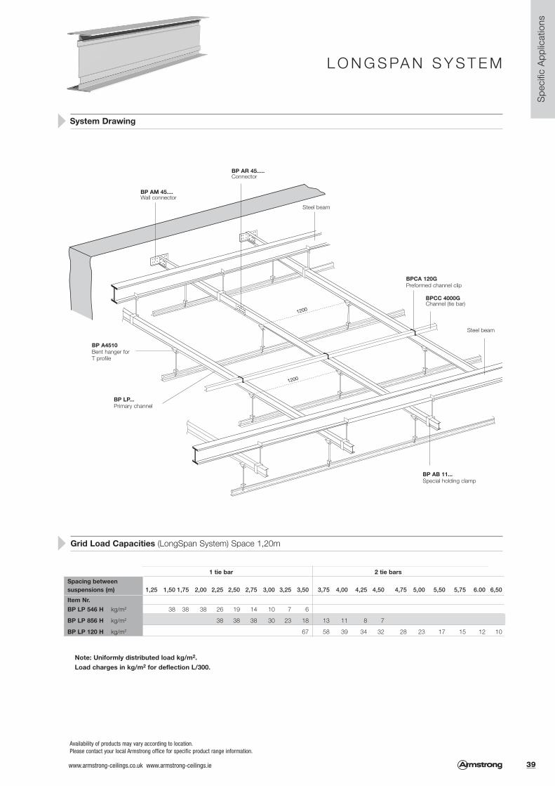
Spe
cific
App
licat
ions
L O N G S PA N S Y S T E M
Availability of products may vary according to location.Please contact your local Armstrong office for specific product range information.
System Drawing
Grid Load Capacities (LongSpan System) Space 1,20m
Note: Uniformly distributed load kg/m2.Load charges in kg/m2 for deflection L/300.
1200
1200
BP AM 45....Wall connector
BP AR 45.....Connector
BP A4510Bent hanger for T profile
BP LP...Primary channel
BP AB 11...Special holding clamp
BPCC 4000GChannel (tie bar)
Steel beam
BPCA 120GPreformed channel clip
Steel beam
1 tie bar 2 tie barsSpacing betweensuspensions (m) 1,25 1,50 1,75 2,00 2,25 2,50 2,75 3,00 3,25 3,50 3,75 4,00 4,25 4,50 4,75 5,00 5,50 5,75 6.00 6,50
Item Nr. BP LP 546 H kg/m2 38 38 38 26 19 14 10 7 6
BP LP 856 H kg/m2 38 38 38 30 23 18 13 11 8 7
BP LP 120 H kg/m2 67 58 39 34 32 28 23 17 15 12 10
39www.armstrong-ceilings.co.uk www.armstrong-ceilings.ie

Met
al A
pplic
atio
ns
ORCAL 1800 SYSTEM Concealed system.For Clip-In 5mm.
For use with 5mm Clip-In Products
Suspension Systems
Item Nr. Description Dimensions Quantity Weight/Cartonmm pcs kg
BP C1801 G Full spring tee 3600 20 51.40
BP C1802 G Half spring tee 3600 10 20,60
BP C3000 G Primary channel 4000 8 23,80
BP C7140 Primary channel splice - 250 11.00
BP C1805 G Full spring tee splice 146 500 17,15
BP C2090 Universal hanger bracket - 200 10,00
BP C1775 A Safety clip for UK spring tee* - - -
19mm x 19mmSuspension angleBPA 952 G
Self drilling screw(optional)
C-channel clampBPCA 97 G
M6 threaded rodBPA 1829 G
M6 Nut for threaded rod BPA 1827 G
* This clip can only be used with tiles that have been ordered with optional security holes.
1. 2.
All measurements in millimetres. All sizes are nominal.For perimeter details, hangers and accessories, please refer to pages 46 - 54.
40 www.armstrong-ceilings.co.uk www.armstrong-ceilings.ie

Met
al A
pplic
atio
ns
ORCAL 1800 SYSTEM
System Drawing (module 600 x 600mm)
Grid Load Capacities
The following table is a guide to the quantity ofsuspension components required for an area of 100m2
using a 600 x 600mm module. No allowance hasbeen made for waste. Quantities may vary accordingto the shape of the actual area.
BPC 2090 – Bracket folded overprimary channel and secured ifnecessary with self-drilling screw.
Tile width Tile Length = Spring Bar Spacing
Hanger spacing = a
Primary channel spacing = b
Orcal tiles are capable of directly supporting limited additional loads from small
service fittings. The maximum total uniformly distributed static load that can be
applied to the rear of a 600x600mm tile should not exceed 3kg. The use of a
pattress is recommended to distribute the load and to minimise face deflection of
the tiles. Loads greater than 3kg should be independently suspended or
supported from the primary grid. The maximum distributed static load that can
be carried by the grid system should not exceed 10 kg/m2.
Availability of products may vary according to location.
Please contact your local Armstrong office for specific product range information
Recommended Spacing & Maximum Loads
a b kg/m2 notes
1500 1500 10 Tiles & Acoustic/Thermal Insulation Only
1200 1200 20 If Additional Service Loads Present
1200 1200 10 For All External Applications
Please contact ITS (0800 371 849 (UK) or 1800 409 002 (ROI)
Fig. Item No. Quantity 100m2 Area
1 BPC3000 G 67 lm
2 BPC1801 G 167 lm
3 Clip-In 5mm tiles 278 pcs
41www.armstrong-ceilings.co.uk www.armstrong-ceilings.ie

Met
al A
pplic
atio
ns
ORCAL 3000 SYSTEMConcealed system.For Clip-In 3mm.
For use with 3mm Clip-In Products
Item Nr. Description Dimensions Quantity Weight/Cartonmm pcs kg
BPM 300100 U-Profile 3750 10 30.00
BPM 300121 Clamping bracket for threaded 100 2,20rod 6mm
BPM 300119 U-Profile connector 100 4,70
BPM 300140 Universal wall anchor 100 3,90
BPM 300120 Plug-In clip 100 0,30
BPM 311149 Half Spring A bar 10 21,30
BPM 311022 Suspension spring A bar 4000 10 20,00
BPM 300138 Suspension spring A bar 100 0,70connector pin
BPM 300105G U-Profile / Spring A bar connector 100 0,60
BPM 300106 Security bracket 100 0,30
BPM 311027 Clip-In System Swing down clip - 100 2,40
BPM 300157 Swing down clip security bracket 100 0,60
BPM 311046 Extractor tool 1
BPC 1502 G Continental hanger bracket 200 10,00
BPC 3000 G Primary channel 4000 8 23,80
All measurements in millimetres. All sizes are nominal.For perimeter details, hangers and accessories, please refer to pages 46 - 54.
Method 1 Method 2
1
2
3
4
5
6 6
7 7
8
9
10
11 11
14
12
13
42 www.armstrong-ceilings.co.uk www.armstrong-ceilings.ie

Met
al A
pplic
atio
ns
ORCAL 3000 SYSTEM
System Drawing (module 600 x 600mm)
Method 1
Method 2
C
A
B
Rigid hanger
Availability of products may vary according to location.
Please contact your local Armstrong office for specific product range information
600 x 600mm module
Dimension A 600mm
Dimension B 1500mm*
Dimension C 1200mm*
*Recommended suspensionconfiguration. The maximumdimension from perimeter walls tothe first hanger position should notexceed 400mm.
12
13
6
43www.armstrong-ceilings.co.uk www.armstrong-ceilings.ie

ORCAL 3000 SYSTEMExposed 100 mm linear grid system (nominal).
For use with Fastrak Products
Suspension System
Met
al A
pplic
atio
ns
Item Nr. Description Dimensions Quantity Weight/Cartonmm pcs kg
BPM 300100 U-Profile 3750 10 30.00
BPM 300121 Clamping bracket for threaded rod 6mm - 100 2,20
BPM 300119 U-Profile connector - 100 4,70
BPM 300140 Universal wall anchor - 100 3,90
BPM 300120 Plug-In clip - 100 0,30
BPM 215500 C-Profile RAL9010 100mm width 4000 4 32,80
BPM 300118 C-Profile hanger bracket - 100 -
BPM 300144 C-Profile connector / wall anchor - 10 0,80
BPM 311067 Connector for C-Profile - 10 8,00
All measurements in millimetres. All sizes are nominal.For perimeter details, hangers and accessories, please refer to pages 46 - 54.
44 www.armstrong-ceilings.co.uk www.armstrong-ceilings.ie

2
9
7
11
6
1
12
ORCAL 3000 SYSTEM
System Drawing
Availability of products may vary according to location.Please contact your local Armstrong office for specific product range information
Met
al A
pplic
atio
nsFig. Item No.
1 BPM 215013 Wall angle
2 BPM 300100 U-Profile
3 BPM 300119 U-Profile connector
4 BPM 300120 Plug-In clip
5 BPM 300121 Clamping bracket
6 BPM 300140 Wall anchor
7 BPM 300144 C-Profile connector /wall anchor
Fig. Item No.
8 BPM 311067 Connector for C- profile
9 BPM 311081 Cut tile spring wedge
10 BPA 1829 G Threaded Rod
11 BPM 311111 Expansion bolt for M6 threaded rod
12 BPM 215500 C-Profile
13 BPM 300118 C-Profile hanger bracket
45www.armstrong-ceilings.co.uk www.armstrong-ceilings.ie

PERIMETER SOLUTIONSMineral suspension system.
BP T 1924 HD Perimeter angle, painted 3000 0,54 36 108,00 22,70
BP T 1924 CA Perimeter angle, capped 3050 0,60 36 109,80 27,60BP T 1924 LB Perimeter angle, 3050 0,55 36 109,80 27,60
corrosive resistant
BP T 1932 HA Perimeter angle, painted 3000 0,45 36 108,00 21,80
BP T 1919 HC Perimeter angle, painted 3000 0,45 36 108,00 19,30
BP T 2400 H Perimeter angle, painted 3050 0,60 30 91,50 20,00intermediate duty
BP T 2401 H Perimeter angle, painted 3050 0,70 30 91,50 22,00heavy duty
BP T 2424 HC Perimeter angle, painted 3050 0,45 36 109,80 21,60
BP T 1506 H Shadowline, painted 3050 0,45 36 109,80 26,30
BP T 1508 HB Shadowline, painted 3050 0,45 36 109,80 27,10
BP T 2020 HH Shadowline, painted 3000 0,65 20 61,00 27,00
BP 7875 G Shadowline, painted, 3050 0,45 30 91,50 26,80for Optima Vector,Ultima Vector
BP T 2121 HG Shadowline, air circulation 3000 0,60 25 75,00 41,25length of slot: 50mmdistance between slots: 20mm approx.16% open area
BP T 2040 HA C-channel, painted 3050 0,45 36 109,80 32,60
BP T 2025 HAG C-channel, painted 3050 0,45 40 122,00 30,00
Item Nr. Description Dimensions Content / Carton Weight / Carton length (mm) thickness (mm) pcs lm kg
Perimeter Trims
Colours available : Carrara (CA), Platinum (PN), Black (BK), RAL 9006 (SG),Brass (BS), Chrome (CE), White RAL 9010 (WR).All measurements in millimetres. All sizes are nominal.
Min
eral
per
imet
er
solu
tions
46 www.armstrong-ceilings.co.uk www.armstrong-ceilings.ie

PERIMETER SOLUTIONSMineral suspension system.
Perimeter Trims
Perimeter Detailing
BP T 2040 HWRA C channel, 3000 0,50 12 36,00 12,50colour RAL 9010
BP T 2040H SG A Perimeter C channel 3050 0,45 20 61 18,10 painted RAL 9006
BP T 1575 HA Unequal U-Profile, 3050 0,45 36 109,80 24,20painted
BP 7856 H F Upstand trim, 3050 0,45 20 61,00 23,70painted, for 16mmthick panels
BP 7852 H F Upstand trim, 3050 0,45 20 61,00 23,00painted, for 13mmthick panels
Item Nr. Description Dimensions Content / Carton Weight / Carton length (mm) thickness (mm) pcs lm kg
Standard perimeter finish with perimeter angleBPT 1924 HD or BPT 1924 CA
Perimeter finish with C channel BPT 2040 HA1 BPA 7890 G Universal retaining clip
BPA 1796 G (page 54) Perimeter wall spring
Perimeter finish with unequal U-Profile BPT 1575 HAPerimeter finish with shadowline BPT 1506 H
24
19
25
6
15 15
ca. 300 ca. 300
ca. 300ca. 300
40
20
32
15 7.5
1
Availability of products may vary according to location.Please contact your local Armstrong office for specific product range information.
BPA 156 G / BPA 246 G (page 53)Perimeter infill for Tegular and MicroLook tiles
Min
eral
per
imet
er
solu
tions
47www.armstrong-ceilings.co.uk www.armstrong-ceilings.ie
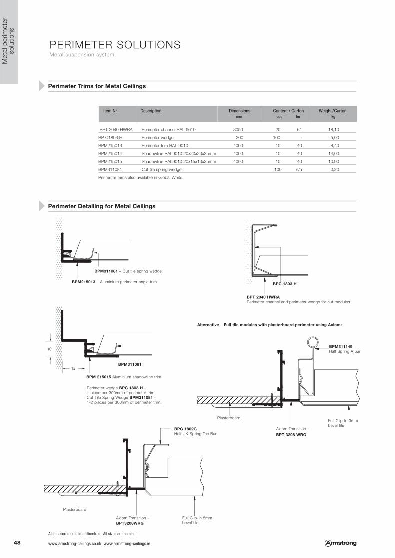
PERIMETER SOLUTIONSMetal suspension system.
BPT 2040 HWRA Perimeter channel RAL 9010 3050 20 61 18,10
BP C1803 H Perimeter wedge 200 100 - 5,00
BPM215013 Perimeter trim RAL 9010 4000 10 40 8,40
BPM215014 Shadowline RAL9010 20x20x20x25mm 4000 10 40 14,00
BPM215015 Shadowline RAL9010 20x15x10x25mm 4000 10 40 10.90
BPM311081 Cut tile spring wedge 100 n/a 0,20
Perimeter trims also available in Global White.
Perimeter Trims for Metal Ceilings
Perimeter Detailing for Metal Ceilings
Item Nr. Description Dimensions Content / Carton Weight / Carton mm pcs lm kg
Met
al p
erim
eter
so
lutio
ns
BPM311081 – Cut tile spring wedge
BPM215013 – Aluminium perimeter angle trim
BPT 2040 HWRAPerimeter channel and perimeter wedge for cut modules
BPM311149Half Spring A bar
BPC 1802GHalf UK Spring Tee Bar
Plasterboard
Plasterboard
Axiom Transition – BPT 3208 WRG
Axiom Transition –BPT3208WRG
Full Clip-In 3mmbevel tile
Full Clip-In 5mmbevel tile
Alternative – Full tile modules with plasterboard perimeter using Axiom:
BPC 1803 H
BPM 215015 Aluminium shadowline trim
Perimeter wedge BPC 1803 H - 1 piece per 300mm of perimeter trim.Cut Tile Spring Wedge BPM311081 - 1-2 pieces per 300mm of perimeter trim.
BPM311081
48 www.armstrong-ceilings.co.uk www.armstrong-ceilings.ie
All measurements in millimetres. All sizes are nominal.

ACCESSORIES
BPA W950 G Suspension wire dia. 2mm approx. 200 metres 1 coil 4,70 41
BPA 1843 G Expanded bolt for threaded rod dia. 6mm 25 100 0,50
BPA 1829 G Threaded rod dia. 6mm 1000 50 lm 8,50
BPA 1839 G Connection for threaded rod dia. 6mm 20 100 0,60
BPA 1827 G Nut for threaded rod 100 0,25
BPA WDN20 H Bent tee bar hanger for threaded rod 57 100 1,40 32
20 (tested with
BPA 14 G Universal clip 40 100 1,00 6mm threaded rod)
BPA WDN21 H Straight suspension clip for Main Runners - 20 1,40 32to Axiom Canopy
BPA WDN23 G Double bent T bar hanger with 57 100 2.26 322 sizes of diameter hole
BPA 11030 G Quick hanger - hook (2 hooks) 165-280 100 5,40
BPA 11020 G Quick hanger - hook (2 hooks) 215-380 100 4,10
BPA 11040 G Quick hanger - hook (2 hooks) 315-580 100 8,50 41
BPA 11070 G Quick hanger - hook (2 hooks) 415-780 100 10,50
BPA 11090 G Quick hanger - hook (2 hooks) 515-980 100 13,00
BPA 12030 G Quick hanger - eye (1 hook +1 eye) 165-280 100 5,20
BPA 12020 G Quick hanger - eye (1 hook +1 eye) 215-380 100 4,10
BPA 12040 G Quick hanger - eye (1 hook +1 eye) 315-580 100 8,30 41
BPA 12070 G Quick hanger - eye (1 hook +1 eye) 415-780 100 10,50
BPA 12090 G Quick hanger - eye (1 hook +1 eye) 515-980 100 13,00
Item Nr. Description Dimensions Content / Carton Weight / Carton Admissible Load *length (mm) pcs kg kg
Suspension & Accessories
* Notes: These admissible loads have been determined from laboratory tests in accordance with EN 13964and apply to the hangers and their grid connections only.No account has been taken of the strength of top fixings which must be selected as appropriate for thesupporting structure and estimated load.
Acc
esso
ries
49www.armstrong-ceilings.co.uk www.armstrong-ceilings.ie

ACCESSORIES
Suspension & Accessories
Item Nr. Description Dimensions Content / Carton Weight / Carton Admissible Load *length (mm) pcs kg kg
* Notes: These admissible loads have been determined from laboratory tests in accordance with EN 13964 and apply to the hangers and their grid connections only.No account has been taken of the strength of top fixings which must be selected as appropriate for the supporting structure and estimated load.
Availability of products may vary according to location.All measurements in millimetres. All sizes are nominal.Please contact your local Armstrong office for specific product range information.
60
190
BPA 10202 H Upper part of nonius 300 100 5,10BPA 10203 H Upper part of nonius 400 100 7,20BPA 10204 H Upper part of nonius 500 100 9,00BPA 10205 H Upper part of nonius 600 100 11,00BPA 10206 H Upper part of nonius 700 100 12,80BPA 10208 H Upper part of nonius 800 100 15,50
33
BPA 10230 G Bottom part of nonius hanger 190 100 4,30
BPA 10229 G Pin to connect bottom 60 100 0,80& upper part of nonius
BPA 952 G Suspension angle 3600 20 13,30
BPA 826 G 2m hanger with hook 2000 100 20,00BPA 827 G 1,7m hanger with hook 1700 100 20,00
BPA 11 G Small hook 125 100 2,00
BPA 12 G Butterfly 100 1,00
BPA 829 G Suspension hanger for T-bar 100 2,00 33
Acc
esso
ries
50 www.armstrong-ceilings.co.uk www.armstrong-ceilings.ie

ACCESSORIES
Suspension & Hold Down Clips
BPA 1837 G Rocking hanger 100 2,00
BPA 1838 G Hanger for wooden beam 100 3,20
BPA 1820 G Beam flange clip 1,6 - 4,8mm thickness 100 2,20
BPA 1821 G Beam flange clip 4,8 - 9,5mm thickness 100 3,20
BPA 1822 G Clip for quick hanger 1,6 - 4,8mm thickness 100 0,80
BPA 1823 G Clip for quick hanger 10 - 15mm thickness 100 3,00
BPA 7890 G Universal retaining clip 100 0,40
BPA 819 G Locking hold down clip, 6-30mm tiles 500 2,40
Item Nr. Description Content / Carton Weight / Cartonpcs kg
82 10
148
18
55
38
BPA 1829
38
Acc
esso
ries
51www.armstrong-ceilings.co.uk www.armstrong-ceilings.ie

ACCESSORIES
Hold Down Clips & Accessories
Item Nr. Description Content / Carton Weight / Cartonpcs kg
BP EHDC 58 AG Exterior hold down clip 150 7,70
BPA 7912 G Hold down clip for 40mm soft fibre panels 100 1,10
BPA 7902 G Hold down clip for 18-25mm soft fibre panels 100 1,10
BPA 425 G Board access clip 100 0,40
BPA 7930 G Last tile clip Tegular 25 0,05
BPA 7931 G Last tile clip MicroLook 25 0,05
BP MCC4 G Mitre closure clip for 6mm Silhouette 200 0,30
BP LFC G Peakform Corner support of lay-in light 50 0,45(Silhouette & 15mm grid)
BPA 131 G T bar saddle clip 100 2,70
70 102
23
66
22
50
32
38
8
424
1. 2. 3.
18
12 16
Availability of products may vary according to location.All measurements in millimetres. All sizes are nominal.Please contact your local Armstrong office for specific product range information.
Acc
esso
ries
52 www.armstrong-ceilings.co.uk www.armstrong-ceilings.ie

ACCESSORIES
Perimeter Accessories
BPA 328 G Inside corner 19mm 100 0,95
BPA 329 G Outside corner 19mm 100 1,25
BPA 330 G Inside corner 24mm 100 0,95
BPA 331 G Outside corner 24mm 100 1,25
BPA 332 G Inside corner for shadowline BP T1508HB 100 1,60
BPA 333 G Outside corner for shadowline BP T1508HB 100 1,20
BPA 0415 G MicroLook border clip 500 0,85
BPA 0324 G Tegular border clip 500 1,15
BPA 156 G Perimeter fill-in for 15mm grid 500 0,40
BPA 246 G Perimeter fill-in for 24mm grid 500 0,50
1513
6
1975
75
o
2413
6
29o
15
246
6.5
Item Nr. Description Content / Carton Weight / Cartonpcs kg
Acc
esso
ries
53www.armstrong-ceilings.co.uk www.armstrong-ceilings.ie
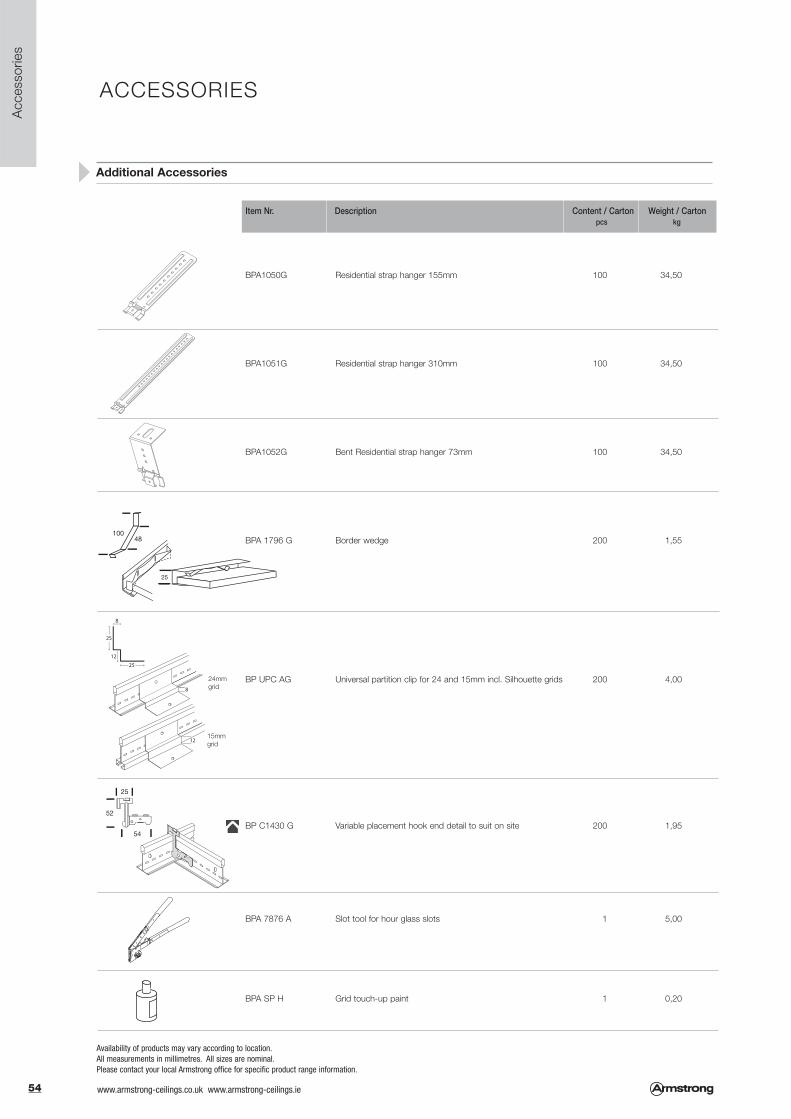
ACCESSORIES
Additional Accessories
Item Nr. Description Content / Carton Weight / Cartonpcs kg
Availability of products may vary according to location.All measurements in millimetres. All sizes are nominal.Please contact your local Armstrong office for specific product range information.
BPA1050G Residential strap hanger 155mm 100 34,50
BPA1051G Residential strap hanger 310mm 100 34,50
BPA1052G Bent Residential strap hanger 73mm 100 34,50
BPA 1796 G Border wedge 200 1,55
BP UPC AG Universal partition clip for 24 and 15mm incl. Silhouette grids 200 4,00
BP C1430 G Variable placement hook end detail to suit on site 200 1,95
BPA 7876 A Slot tool for hour glass slots 1 5,00
BPA SP H Grid touch-up paint 1 0,20
24mmgrid
15mmgrid
Acc
esso
ries
54 www.armstrong-ceilings.co.uk www.armstrong-ceilings.ie

FIRE PERFORMANCE
The fire performance of floor structures protected by Armstrong ceilingtile and grid systems is given in the fire assessment document 173816.
This document is based on a large number of fire tests conducted byArmstrong on various ceiling tile and grid types. It provides a summaryof the performances attainable when the complete Armstrong tile andgrid system is installed in accordance with the appropriate base firetest and the installation variations from the base tests that arepermitted.
The document assesses the performance of the majority of the different types of Cross Tee and Main Runners manufactured byArmstrong and covers TLX, XL2, TL standard and TLX CorrosiveResistant Cross Tees in conjunction with standard and Corrosive Resistant Peakform or square bulb Universal Main Runners.
Armstrong testing is generally conducted with the ceiling tiles clippeddown, except for certain products under certain conditions belowmezzanine floors.
This is to prevent any lifting of the tiles during a fire due to a pressurespike or accidental removal of tiles during the operation of the buildingwhich could stop the ceiling from providing the required protection.The last tiles in these situations must also be secured using theappropriate last tile clip, which also highlights the access point to theceiling. Full details regarding the use of clips are given in theassessment document.
The tables below give a summary of the performances achievable asstated in the assessment document at the time of going to print. Thecurrent version of the assessment document 173816 and therelevant base test report should always be consulted prior tothe installation of a floor construction to be protected by anArmstrong ceiling system. Copies of the assessment and base testsare freely available from our Internal Technical Sales Team on:
Freefone 0800 371849 (UK) or 1800 409002 (RoI) or via email at [email protected]
Assessed Performance Under Structural Steel Beams - Base Test Report: 134086 (70995 for Clip-In)
Assessed Performance Under Timber Floors - Base Test Report: 167751
Board Tegular MicroLook SecondLook Flush Tegular Clip-In 3mm CommentsUltima 90 minutes 60 minutes 60 minutes n/a n/a n/a Includes 500 x 500 and 1200 x 300 MicroLook UltimaUltima dB 60 minutes 60 minutes 60 minutes n/a n/a n/aUltima OP 30 minutes n/a n/a n/a n/a n/aPerla 60 minutes 60 minutes 60 minutes n/a n/a n/aPerla OP 30 minutes n/a n/a n/a n/a n/aSierra 60 minutes 60 minutes 60 minutes n/a n/a n/aBioguard Acoustic 60 minutes 60 minutes 60 minutes n/a n/a n/aBioguard Plain 60 minutes 60 minutes 60 minutes n/a n/a n/aDune dB 60 minutes 60 minutes 60 minutes n/a n/a n/aDune Supreme 60 minutes 60 minutes 30 minutes n/a n/a n/aDune Max 60 minutes 60 minutes 30 minutes n/a n/a n/aDune Plus 60 minutes 60 minutes 30 minutes n/a n/a n/a Includes all 500 x 500 and Colortone Dune Plus tilesFine Fissured 60 minutes 60 minutes 30 minutes 60 minutes n/a n/a Includes Colortone Black, but NOT Sektor or FrequencePlain 60 minutes 60 minutes 30 minutes n/a n/a n/a Does NOT include GraphisCirrus 60 minutes 60 minutes 30 minutes n/a n/a n/a Does NOT include any Cirrus Design tilesTatra 60 minutes 60 minutes n/a n/a n/a n/aCortega 60 minutes 60 minutes n/a n/a n/a n/aMezzanine DL 100 60 minutes n/a n/a n/a n/a n/aOrcal Plain + pad or B15 60 minutes 60 minutes 60 minutes n/a 60 minutes n/a 8mm and 16mm returns. 18mm 100kg/m3 AFBTF padOrcal Std Perf + pad or B15 60 minutes 60 minutes 60 minutes n/a 60 minutes n/a 8mm and 16mm returns. 18mm 100kg/m3 AFBTF padOrcal Microperf + pad or B15 60 minutes 60 minutes 60 minutes n/a 60 minutes n/a 8mm and 16mm returns. 18mm 100kg/m3 AFBTF padOrcal Extra Microperf + pad or B15 60 minutes 60 minutes 60 minutes n/a 60 minutes n/a 8mm and 16mm returns. 18mm 100kg/m3 AFBTF padOrcal Plain + pad n/a n/a n/a n/a n/a 30 minutes 600 x 600 only. 40mm 45kg/m3 AFBTF padOrcal Std Perf + pad n/a n/a n/a n/a n/a 30 minutes 600 x 600 only. 40mm 45kg/m3 AFBTF padOrcal Microperf + pad n/a n/a n/a n/a n/a 30 minutes 600 x 600 only. 40mm 45kg/m3 AFBTF padOrcal Extra Microperf + pad n/a n/a n/a n/a n/a 30 minutes 600 x 600 only. 40mm 45kg/m3 AFBTF pad
Board Tegular MicroLook SecondLook Flush Tegular Clip-In 3mm CommentsUltima 60 minutes 60 minutes 60 minutes n/a n/a n/aUltima dB 60 minutes 60 minutes 60 minutes n/a n/a n/aDune dB 60 minutes 60 minutes 60 minutes n/a n/a n/a Main runners at 600mm centres onlyMezzanine DL 100 60 minutes n/a n/a n/a n/a n/aFine Fissured n/a n/a n/a 60 minutes n/a n/aUltima 30 minutes 30 minutes 30 minutes n/a n/a n/aUltima dB 30 minutes 30 minutes 30 minutes n/a n/a n/aDune dB 30 minutes 30 minutes 30 minutes n/a n/a n/aMezzanine DL 100 30 minutes n/a n/a n/a n/a n/aPerla 30 minutes 30 minutes n/a n/a n/a n/aSierra 30 minutes 30 minutes n/a n/a n/a n/aBioguard Acoustic 30 minutes 30 minutes n/a n/a n/a n/aBioguard Plain 30 minutes 30 minutes n/a n/a n/a n/aDune Supreme 30 minutes 30 minutes n/a n/a n/a n/aDune Max 30 minutes 30 minutes n/a n/a n/a n/aDune Plus 30 minutes 30 minutes n/a n/a n/a n/a Includes Colortone Dune Plus tilesFine Fissured 30 minutes 30 minutes n/a 30 minutes n/a n/a Includes Colortone Black, but NOT Sektor or FrequencePlain 30 minutes 30 minutes n/a n/a n/a n/a Does NOT include GraphisCirrus 30 minutes 30 minutes n/a n/a n/a n/a Does NOT include any Cirrus Design tilesTatra 30 minutes 30 minutes n/a n/a n/a n/aCortega 30 minutes 30 minutes n/a n/a n/a n/a
Assessed Performance Under Mezzanine Floors - Base Test Report: 120559
Board Tegular MicroLook SecondLook Flush Tegular Clip-In 3mm CommentsUltima 60 minutes 60 minutes 30 minutes n/a n/a n/aUltima dB 60 minutes 60 minutes 30 minutes n/a n/a n/aDune dB 60 minutes 60 minutes 30 minutes n/a n/a n/aMezzanine DL 100 60 minutes n/a n/a n/a n/a n/aPerla 30 minutes 30 minutes n/a n/a n/a n/aSierra 30 minutes 30 minutes n/a n/a n/a n/aBioguard Acoustic 30 minutes 30 minutes n/a n/a n/a n/aBioguard Plain 30 minutes 30 minutes n/a n/a n/a n/aDune Supreme 30 minutes 30 minutes n/a n/a n/a n/aDune Max 30 minutes 30 minutes n/a n/a n/a n/aDune Plus 30 minutes 30 minutes n/a n/a n/a n/a Includes Colortone Dune Plus tilesFine Fissured 30 minutes 30 minutes n/a 60 minutes n/a n/a Includes Colortone Black, but NOT Sektor or FrequencePlain 30 minutes 30 minutes n/a n/a n/a n/a Does NOT include GraphisCirrus 30 minutes 30 minutes n/a n/a n/a n/a Does NOT include any Cirrus Design tilesTatra 30 minutes 30 minutes n/a n/a n/a n/aCortega 30 minutes 30 minutes n/a n/a n/a n/a
55www.armstrong-ceilings.co.uk www.armstrong-ceilings.ie

LOAD CAPACITY MATRIXLoad values determined from laboratory tests in accordance with EN 13964.
System Load Summary (1200 x 1200 layout) - Max Load kg/m2 - Deflection factor only
56 www.armstrong-ceilings.co.uk www.armstrong-ceilings.ie
System Main Runner Primary Secondary L/500 L/400 L/360 L/300Cross Tee Cross Tee (2,4mm) (3mm) (3,3mm) (4mm)
Prelude 24 XL2 BP314032A BP313051B BP312021A 13,3 16,8 18,8 22,7
Prelude 24 TLX BP314032A BP133031 BP132031 13,3 16,8 18,7 22,7
Prelude 15 XL2 BP304033A BP303033B BP302033B 13,1 16,5 18,5 22,3
Prelude 15 TL BP304033A BP103033A BP102033A 13,1 16,5 18,5 22,3
Silhouette 15 XL2 BP804042G BP803042G BP802042G 11,4 14,4 16,1 19,5
Interlude 15 XL2 BP614042G BP613042G BP612042G 14,5 18,3 20,4 24,7
Prelude 35 BP124033A BP123033A BP122033A 12,6 16,1 18,0 21,8
Prelude 24 CR - TLX BP284042 BP143032 BP142032 13,3 16,8 18,7 22,7
CLEAN ROOM 24 BPEA794044 BPEA793044 BPEA792044 12,8 16,3 18,2 22,1
System Load Summary (1200x1800 layout) - Max Load kg/m2 - Deflection factor only
System Main Runner Primary Secondary L/500 L/400 L/360 L/300Cross Tee Cross Tee (3,6mm) (4mm) (4mm) (4mm)
Prelude 24 XL2 BP314032A BP313431A BP312021A 6,3 7,1 7,1 7,1(1800 span)Prelude 24 TLX BP314032A BP133432 BP132031 6,3 7,1 7,1 7,1(1800 span)
System Load Summary (1800x1800 layout) - Max Load kg/m2 - Deflection factor only
System Main Runner Primary Secondary L/500 L/400 L/360 L/300Cross Tee Cross Tee (3,6mm) (4mm) (4mm) (4mm)
Prelude Sixty2 24 - XL2 BP404093G BP313431A BP312021A 6,3 7,1 7,1 7,1
Prelude Sixty2 24 - TLX BP404093G BP133432 BP132031 6,3 7,1 7,1 7,1
1200mmspacing
1200mmCross Tees
MRMR
600mm
1200mmspacing
1800mmCross Tees
MRMR
600mm
1800mmspacing
1800mmCross Tees
MRMR
600mm

PG 2
901
Pro
duce
d by
The
Des
ign
Quo
rum
, Ger
rard
s C
ross
, Buc
ks U
K. T
el: 0
1753
891
707
Printed on chlorine free paper from sustainable resources
Western Europe
Belgium & LuxembourgArmstrong Building Products B.V.Bureaux Commerciaux BelgiqueOffice Building QuadriumClaudius Prinsenlaan 1264818 CP BredaNederlandTel: (+32) 02 223 00 72 Fax: (+31) 076 521 04 07 e-mail: [email protected]
Germany & SwitzerlandArmstrong Building ProductsKundenserviceOffice Building QuadriumClaudius Prinsenlaan 1264818 CP BredaNiederlandeTel: (+49) 0251 7603 210Fax: (+49) 0251 7603 593e-Mail: deutsche-info@armstrong.comwww.armstrong-decken.dewww.armstrong-decken.atwww.armstrong.ch
FirmensitzArmstrong Building Products GmbHRobert-Bosch Strasse 1048153 MünsterDeutschland
SpainArmstrong Building ProductsOficina de ventas EspañaImmeuble Paryseine3 Allée de la Seine94854 Ivry-sur-SeineFranciaTel: (+ 34) 91 642 04 99
00 800 90 21 03 68Fax: (+33) 1 4521 04 11e-mail: [email protected]/techos
Sede SocialArmstrong Architectural Products SLAribau, 308, Entresuelo 1a08006 BarcelonaEspaña
PortugalArmstrong Floor ProductRua de Manuel Assunçao de Falcao, 634475-041 Santa Maria de Avioso - MaiaPortugalTel.: (+351) 22 982 81 10Fax: (+351) 22 982 81 [email protected]
France & French Speaking AfricaArmstrong Building Products SASBureaux Commerciaux FranceImmeuble Paryseine3 Allée de la Seine94854 Ivry-sur-Seine
: 0800 41 36 43Fax: (+33) 1 45 21 04 11e-mail: [email protected]/plafonds
Siège socialArmstrong Building Products SAS67 Rue de SalinsBP 8925300 PontarlierFrance
Italy & GreeceArmstrong Building ProductsUfficio Commerciale ItaliaImmeuble Paryseine3 Allée de la Seine94854 Ivry-sur-SeineFranciaTel: (+39) 02 66 22 76 50Fax: (+39) 02 66 20 14 27e-mail: info-italia@armstrong.comwww.armstrong-soffitti.itwww.armstrong-europe.com
Sede Legale:Armstrong Building Products s.r.lVicolo Diomede Pantaleoni, 420 161 MilanoItalia
NetherlandsArmstrong Building Products B.V.Verkoopkantoor NederlandOffice Building QuadriumClaudius Prinsenlaan 1264818 CP BredaNederlandTel: (+31) 076 521 77 33Fax: (+31) 076 521 04 07e-mail: [email protected]/plafonds
HoofdkantoorArmstrong Building Products BVNoorderstraat 163-1659611 AD SappemeerHolland
United KingdomArmstrong World Industries LtdBuilding Products DivisionArmstrong House38 Market SquareUxbridge UB8 1NG
: 0800 371849 Fax: (+44) 1895 274287e-mail: [email protected]
Republic of IrelandArmstrong World Industries Ltd.108 Greenlea RoadTerenureCo Dublin 6WIreland
Tel: 1800 409002 Tel: (00) 3531 4991701Fax: (00) 3531 4907061e mail: [email protected]
Central Europe North
(DK/EE/FIN/IS/LT/LV/N/PL/S)Armstrong Building Products BVSp.z.o.o. Oddzia! w Polsceul. Domaniewska 3702-672 WarszawaPolandTel: (+48) 0 22 337 86 10/ 86 11Fax: (+48) 0 22 337 86 12e-mail: [email protected]
Latvia www.armstrong.lvLithuania www.armstrong.ltNorway www.armstrong.noPoland www.armstrong.plSweden www.armstrong.se
Central Europe South
(CZ/H/RO/SK/SL)Bureaux Commerciaux FranceImmeuble Paryseine3 Allée de la Seine94854 Ivry-sur-SeineTel: (+33) 1 43 90 45 40Fax: (+33) 1 45 21 04 11e-mail: [email protected]
Czech Republic www.armstrong.czHungary www.armstrong.co.huRomania www.armstrong.roSerbia: www.armstrong.rsSlovakia www.armstrong.skSlovenia www.armstrong.si
Eastern EuropeCISArmstrong Moscow GmbHPark Place, office E502# 113/1, Leninsky ProspektMoscow 117198RussiaTel: (+7) 495 956 5100Fax: (+7) 495 956 5101e-mail: [email protected]
Russian Federation www.armstrong.ruUkraine/Belarus www.armstrong.com.uaKhazahkstan www.armstrong.kzKyrgyzstan www.armstrong.kgUzbekistan www.armstrong.uz
Africa/Middle East/Turkey
Armstrong World Industries LtdAfrica Middle East Turkey DivisionArmstrong House38 Market SquareUxbridge UB8 1NGTel: (+44) 01895 251122Fax: (+44) 01895 272928e-mail: [email protected]
Israël www.armstrong.co.ilSouth Africa www.armstrong-ceilings.zaTurkey www.armstrong.com.tr
Asia
IndiaArmstrong World Industries (India) Pvt Ltd3rd floor, “C” Wing, Mhatre Pen BuildingSenapati Bapat MargDadar WestMUMBAI 400 028IndiaTel: (+91) 22 2430 4574/4580Fax: (+91) 22 2430 4506www.armstrong.in
APPEL GRATUIT FREEFONE
FREEFONE
LLAMADA GRATIUTA
All photographic and design elements supplied in this brochure
do not necessarily reflect any recommendation by any of the
companies named in this brochure as to the proper use or
recommended methods of installation of suspended ceilings
and are supplied only as informative material.
For technical reasons in printing, differences may appear
between colours printed in this brochure and the actual
product. The choice of colours should always be made from a
sample of the product.
All statements and technical information contained in this
brochure, or any publication of the companies named in this
brochure, relating to Armstrong ceilings are based on results
obtained under laboratory test conditions. It is the responsibility
of the user to verify with the seller of the products in writing
that such statements and information are appropriate to the
specific use intended. Sales of the products and liability of the
selling companies are in accordance with the terms and
conditions of sale of the selling company.
All product specifications are subject to modifications without
prior notice.
Advisory note
www.armstrong-ceilings.ie www.armstrong-ceilings.co.uk
53