truss bridges - concrete e-learning platform
TRANSCRIPT

Special girder bridges
03.05.2021 1
Truss bridges
ETH Zürich | Chair of Concrete Structures and Bridge Design | Bridge Design Lectures
Skew bridges
IntroductionIntroduction
03.05.2021 2ETH Zürich | Chair of Concrete Structures and Bridge Design | Bridge Design Lectures
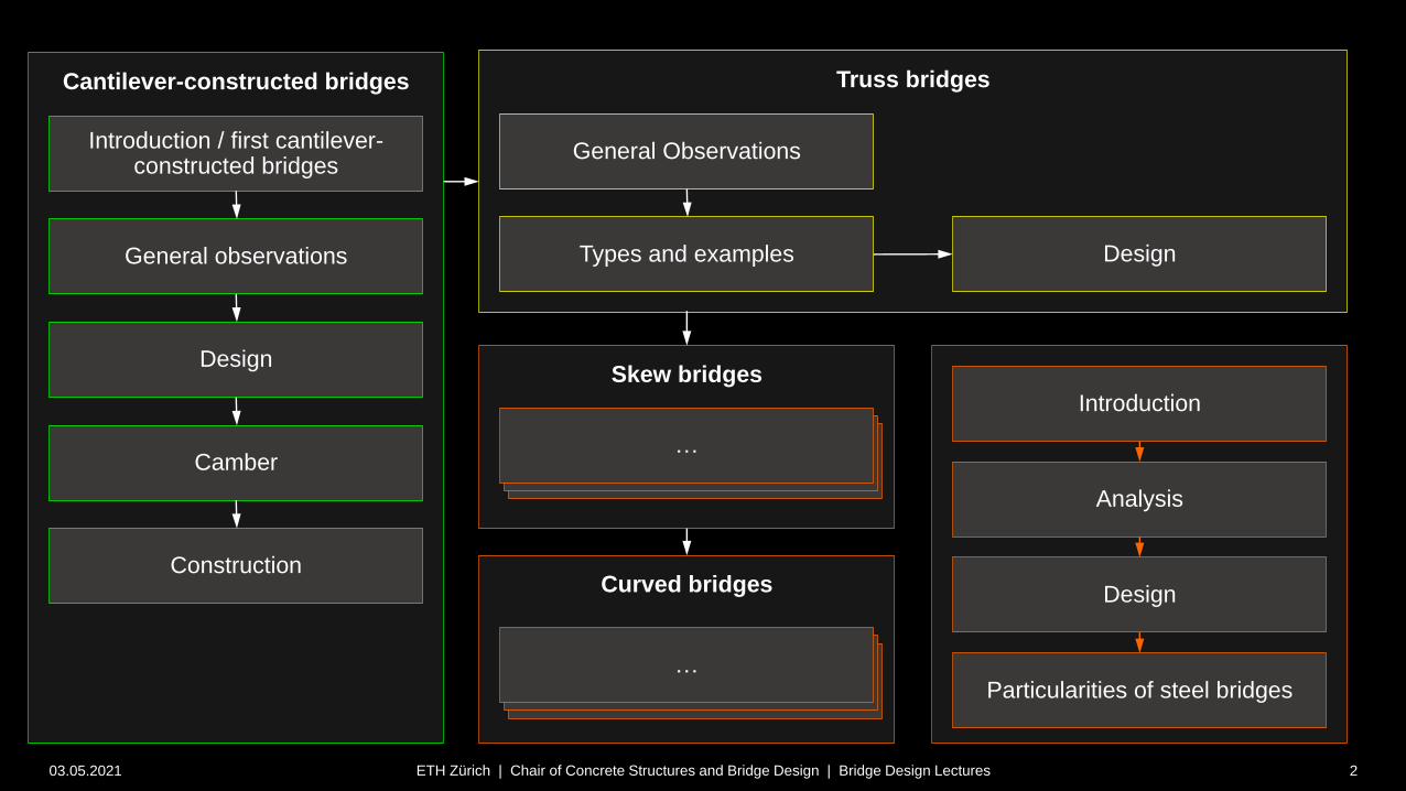
Cantilever-constructed bridges
Introduction / first cantilever-constructed bridges
General observations
Introduction
Analysis
Design
Truss bridges
General Observations
Types and examples
Design
Camber
Construction
Particularities of steel bridges
…
Curved bridges
IntroductionIntroduction…
Design

Special girder bridges
03.05.2021 3
Truss bridges
General observations
ETH Zürich | Chair of Concrete Structures and Bridge Design | Bridge Design Lectures
Truss bridges – General observations
03.05.2021 4ETH Zürich | Chair of Concrete Structures and Bridge Design | Bridge Design Lectures
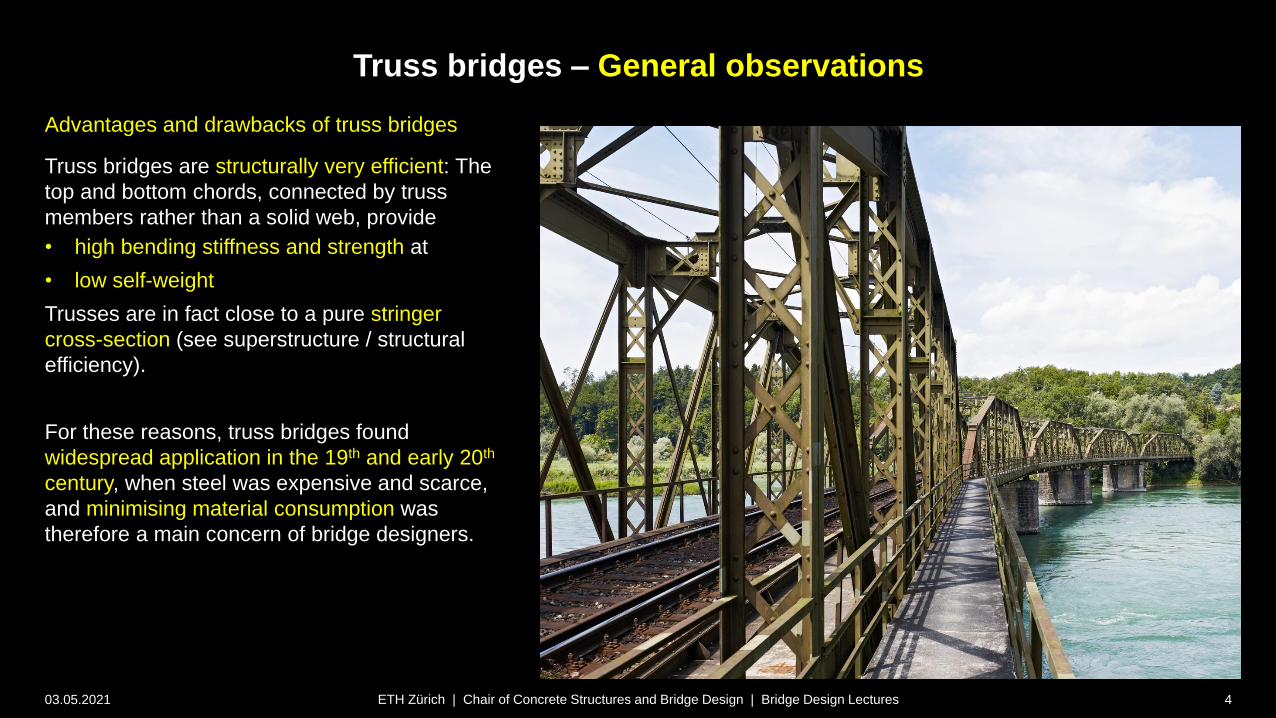
Advantages and drawbacks of truss bridges
Truss bridges are structurally very efficient: The
top and bottom chords, connected by truss
members rather than a solid web, provide
• high bending stiffness and strength at
• low self-weight
Trusses are in fact close to a pure stringer
cross-section (see superstructure / structural
efficiency).
For these reasons, truss bridges found
widespread application in the 19th and early 20th
century, when steel was expensive and scarce,
and minimising material consumption was
therefore a main concern of bridge designers.
Truss bridges – General observations
03.05.2021 5ETH Zürich | Chair of Concrete Structures and Bridge Design | Bridge Design Lectures
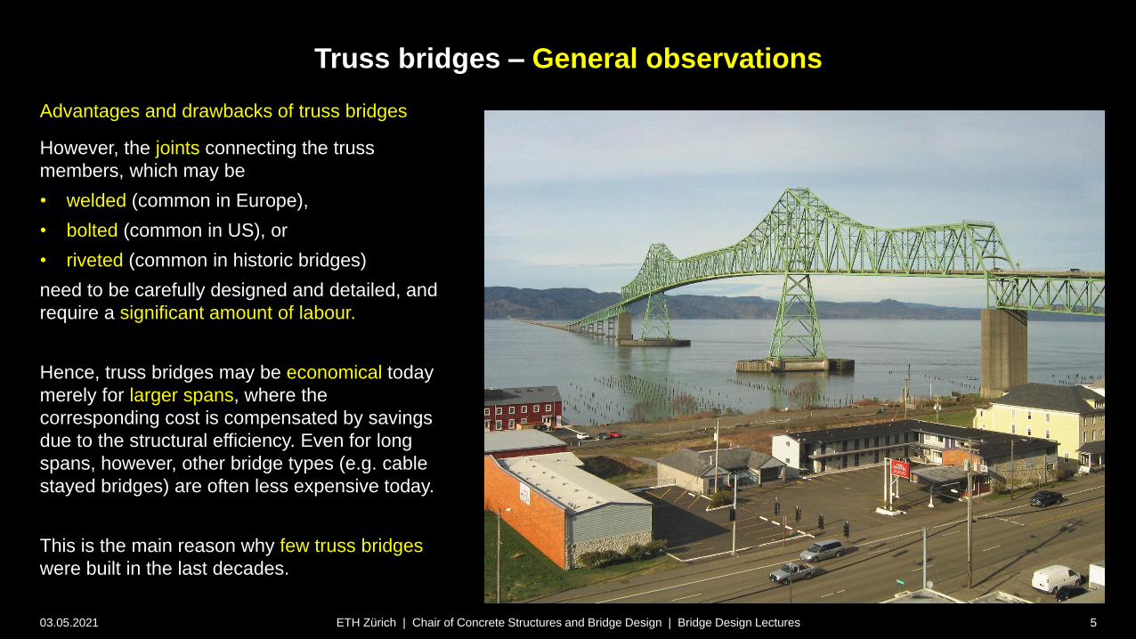
Advantages and drawbacks of truss bridges
However, the joints connecting the truss
members, which may be
• welded (common in Europe),
• bolted (common in US), or
• riveted (common in historic bridges)
need to be carefully designed and detailed, and
require a significant amount of labour.
Hence, truss bridges may be economical today
merely for larger spans, where the
corresponding cost is compensated by savings
due to the structural efficiency. Even for long
spans, however, other bridge types (e.g. cable
stayed bridges) are often less expensive today.
This is the main reason why few truss bridges
were built in the last decades.
Truss bridges – General observations
03.05.2021 6ETH Zürich | Chair of Concrete Structures and Bridge Design | Bridge Design Lectures
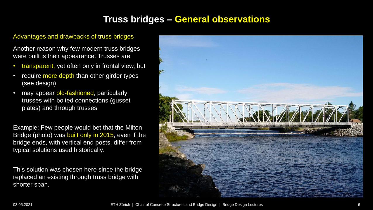
Advantages and drawbacks of truss bridges
Another reason why few modern truss bridges
were built is their appearance. Trusses are
• transparent, yet often only in frontal view, but
• require more depth than other girder types
(see design)
• may appear old-fashioned, particularly
trusses with bolted connections (gusset
plates) and through trusses
Example: Few people would bet that the Milton
Bridge (photo) was built only in 2015, even if the
bridge ends, with vertical end posts, differ from
typical solutions used historically.
This solution was chosen here since the bridge
replaced an existing through truss bridge with
shorter span.

Truss bridges – General observations
03.05.2021 7ETH Zürich | Chair of Concrete Structures and Bridge Design | Bridge Design Lectures
Advantages and drawbacks of truss bridges
Further disadvantages of truss bridges, limiting their use in
modern bridge design, are:
• High maintenance demand due to large exposed surfaces,
particularly in through and pony trusses not protected by
the deck
• Typically trusses are isostatic, such that all individual
members are “fracture critical”: Failure of one member will
lead to a global collapse.
The photos show the I35-W Mississippi bridge, which
collapsed in 2007 during resurfacing works. Presumably,
failure of undersized gusset plates triggered the collapse
(construction equipment and up to 5 cm concrete/pavement
added since original construction caused high loads).
Note that redundancy can be achieved by providing extra
trusses running in parallel, such that one truss may fail without
causing global collapse. However, this causes high extra cost.

Special girder bridges
03.05.2021 8
Truss bridges
Types and examples
ETH Zürich | Chair of Concrete Structures and Bridge Design | Bridge Design Lectures
Truss bridges – Types and examples
03.05.2021 9ETH Zürich | Chair of Concrete Structures and Bridge Design | Bridge Design Lectures
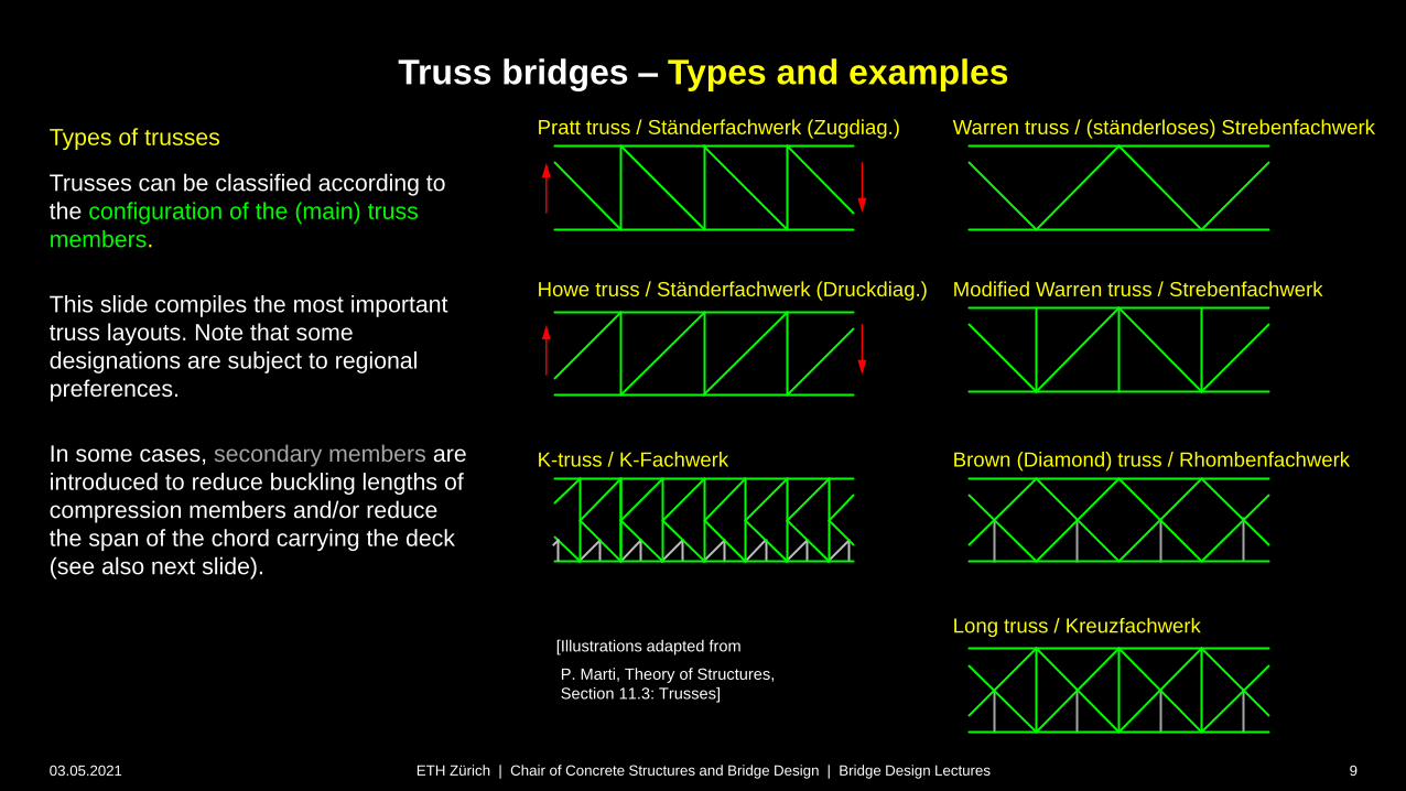
Types of trusses
Trusses can be classified according to
the configuration of the (main) truss
members.
This slide compiles the most important
truss layouts. Note that some
designations are subject to regional
preferences.
In some cases, secondary members are
introduced to reduce buckling lengths of
compression members and/or reduce
the span of the chord carrying the deck
(see also next slide).
[Illustrations adapted from
P. Marti, Theory of Structures,
Section 11.3: Trusses]
Pratt truss / Ständerfachwerk (Zugdiag.)
Howe truss / Ständerfachwerk (Druckdiag.)
K-truss / K-Fachwerk
Warren truss / (ständerloses) Strebenfachwerk
Modified Warren truss / Strebenfachwerk
Brown (Diamond) truss / Rhombenfachwerk
Long truss / Kreuzfachwerk
Truss bridges – Types and examples
03.05.2021 10ETH Zürich | Chair of Concrete Structures and Bridge Design | Bridge Design Lectures
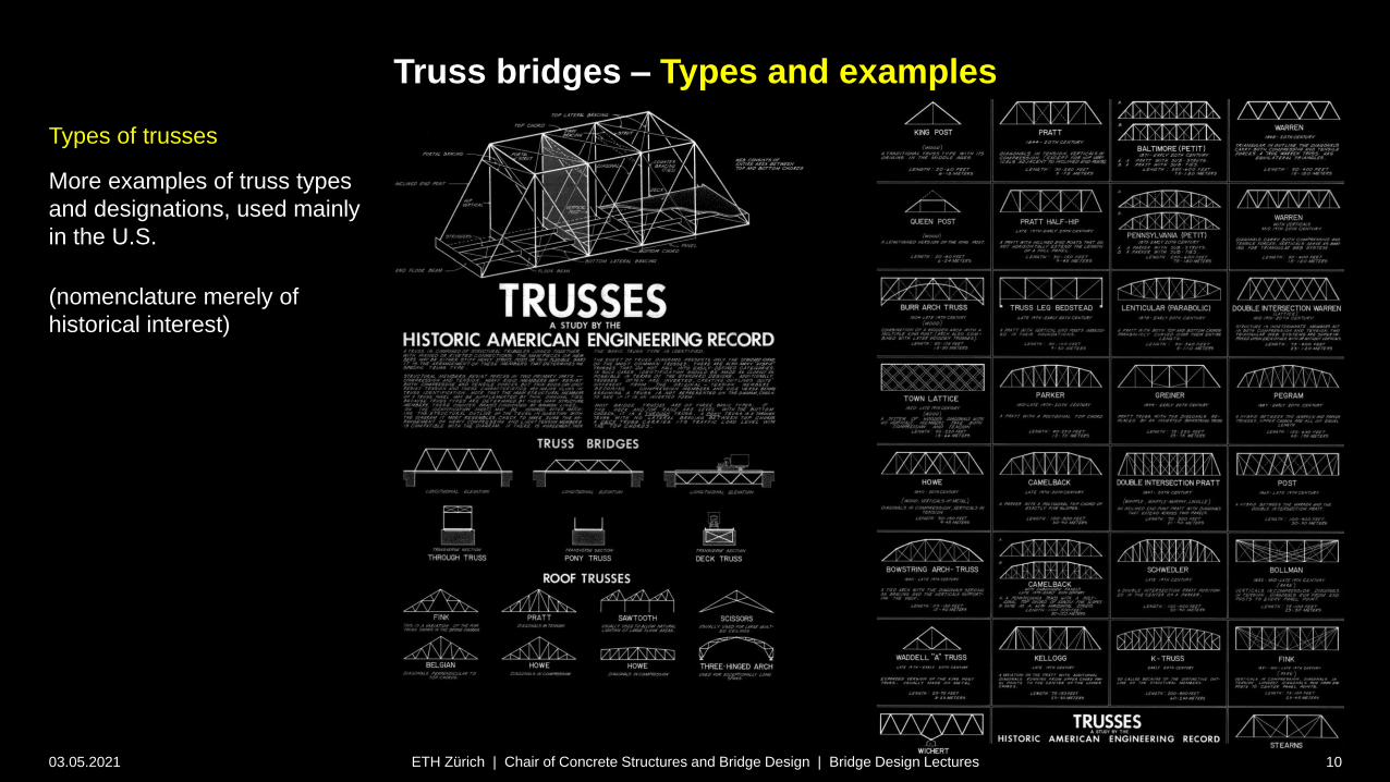
Types of trusses
More examples of truss types
and designations, used mainly
in the U.S.
(nomenclature merely of
historical interest)
Truss bridges – Types and examples
03.05.2021 11ETH Zürich | Chair of Concrete Structures and Bridge Design | Bridge Design Lectures
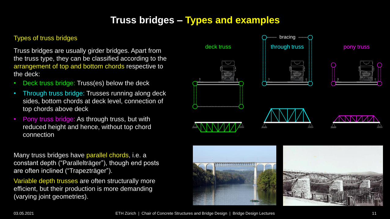
Types of truss bridges
Truss bridges are usually girder bridges. Apart from
the truss type, they can be classified according to the
arrangement of top and bottom chords respective to
the deck:
• Deck truss bridge: Truss(es) below the deck
• Through truss bridge: Trusses running along deck
sides, bottom chords at deck level, connection of
top chords above deck
• Pony truss bridge: As through truss, but with
reduced height and hence, without top chord
connection
Many truss bridges have parallel chords, i.e. a
constant depth (“Parallelträger”), though end posts
are often inclined (“Trapezträger”).
Variable depth trusses are often structurally more
efficient, but their production is more demanding
(varying joint geometries).
deck truss through truss pony truss
bracing
Truss bridges – Types and examples
03.05.2021 12ETH Zürich | Chair of Concrete Structures and Bridge Design | Bridge Design Lectures
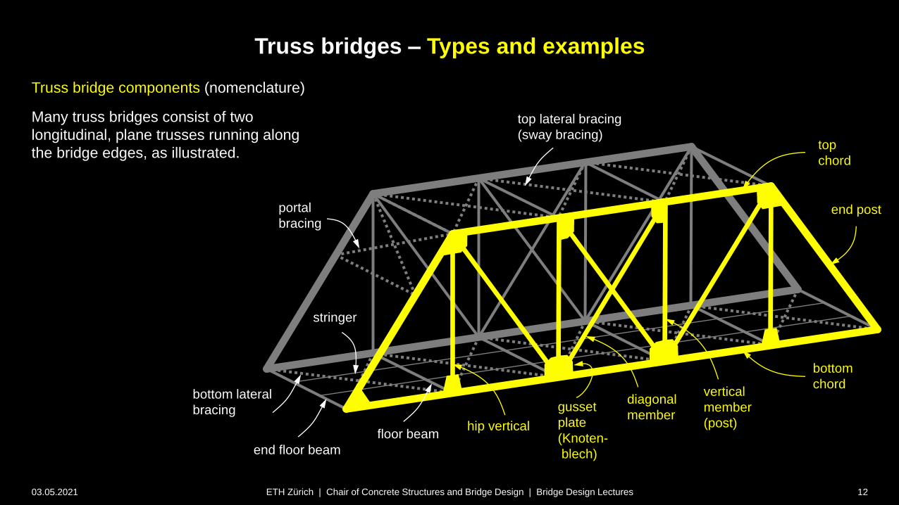
Truss bridge components (nomenclature)
Many truss bridges consist of two
longitudinal, plane trusses running along
the bridge edges, as illustrated.top
chord
bottom
chord
end floor beam
stringer
portal
bracing
top lateral bracing
(sway bracing)
floor beam
end post
hip vertical
diagonal
member
vertical
member
(post)
bottom lateral
bracing gusset
plate
(Knoten-
blech)
Truss bridges – Types and examples
03.05.2021 13ETH Zürich | Chair of Concrete Structures and Bridge Design | Bridge Design Lectures
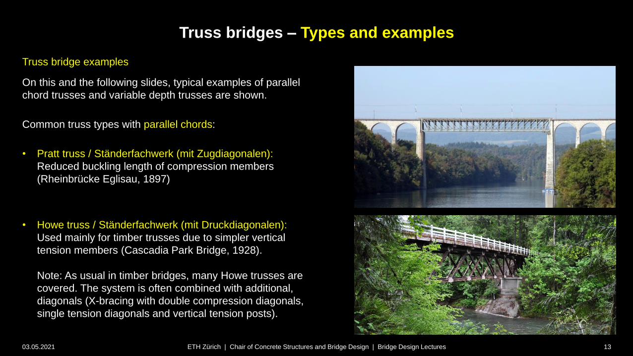
Truss bridge examples
On this and the following slides, typical examples of parallel
chord trusses and variable depth trusses are shown.
Common truss types with parallel chords:
• Pratt truss / Ständerfachwerk (mit Zugdiagonalen):
Reduced buckling length of compression members
(Rheinbrücke Eglisau, 1897)
• Howe truss / Ständerfachwerk (mit Druckdiagonalen):
Used mainly for timber trusses due to simpler vertical
tension members (Cascadia Park Bridge, 1928).
Note: As usual in timber bridges, many Howe trusses are
covered. The system is often combined with additional,
diagonals (X-bracing with double compression diagonals,
single tension diagonals and vertical tension posts).
Truss bridges – Types and examples
03.05.2021 14ETH Zürich | Chair of Concrete Structures and Bridge Design | Bridge Design Lectures
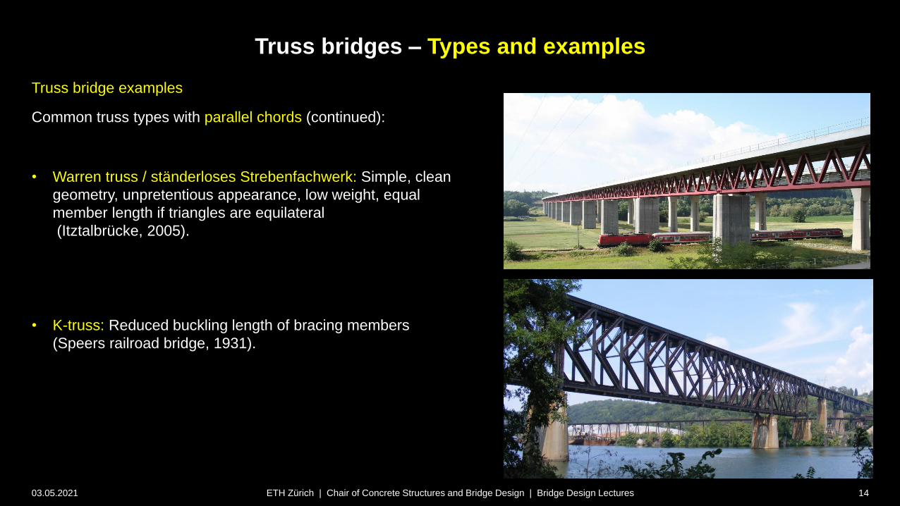
Truss bridge examples
Common truss types with parallel chords (continued):
• Warren truss / ständerloses Strebenfachwerk: Simple, clean
geometry, unpretentious appearance, low weight, equal
member length if triangles are equilateral
(Itztalbrücke, 2005).
• K-truss: Reduced buckling length of bracing members
(Speers railroad bridge, 1931).
Truss bridges – Types and examples
03.05.2021 15ETH Zürich | Chair of Concrete Structures and Bridge Design | Bridge Design Lectures
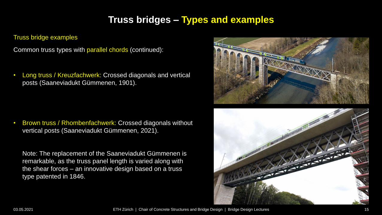
Truss bridge examples
Common truss types with parallel chords (continued):
• Long truss / Kreuzfachwerk: Crossed diagonals and vertical
posts (Saaneviadukt Gümmenen, 1901).
• Brown truss / Rhombenfachwerk: Crossed diagonals without
vertical posts (Saaneviadukt Gümmenen, 2021).
Note: The replacement of the Saaneviadukt Gümmenen is
remarkable, as the truss panel length is varied along with
the shear forces – an innovative design based on a truss
type patented in 1846.
Truss bridges – Types and examples
03.05.2021 16ETH Zürich | Chair of Concrete Structures and Bridge Design | Bridge Design Lectures
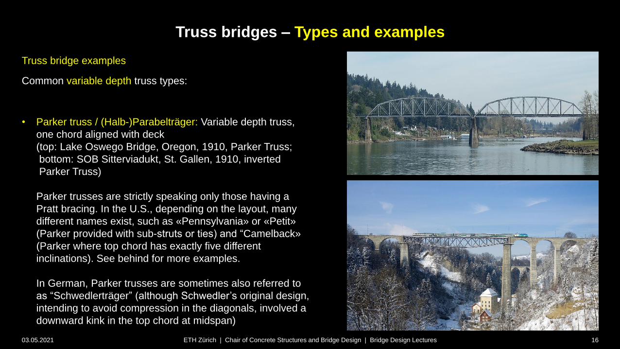
Truss bridge examples
Common variable depth truss types:
• Parker truss / (Halb-)Parabelträger: Variable depth truss,
one chord aligned with deck
(top: Lake Oswego Bridge, Oregon, 1910, Parker Truss;
bottom: SOB Sitterviadukt, St. Gallen, 1910, inverted
Parker Truss)
Parker trusses are strictly speaking only those having a
Pratt bracing. In the U.S., depending on the layout, many
different names exist, such as «Pennsylvania» or «Petit»
(Parker provided with sub-struts or ties) and “Camelback»
(Parker where top chord has exactly five different
inclinations). See behind for more examples.
In German, Parker trusses are sometimes also referred to
as “Schwedlerträger” (although Schwedler’s original design,
intending to avoid compression in the diagonals, involved a
downward kink in the top chord at midspan)

Truss bridges – Types and examples
03.05.2021 17ETH Zürich | Chair of Concrete Structures and Bridge Design | Bridge Design Lectures
Truss bridge examples
Common variable depth truss types:
• Lenticular truss / Pauliträger: Variable depth truss, both
chords curved, typically Pratt or cross bracings
(top: first SBB Aarebrücke Brugg, 1875; bottom: Royal
Albert Bridge, 1859).
Note that this layout is inefficient since neither of the chords
is aligned with the deck. Few bridges were built for this
reason.

Truss bridges – Types and examples
03.05.2021 18ETH Zürich | Chair of Concrete Structures and Bridge Design | Bridge Design Lectures
Truss bridge examples
Common variable depth truss types:
• Cantilever truss: Variable depth trusses, with maximum
depth over piers to enable cantilever construction of the
bridge.
This typology is very useful particularly for crossing
obstacles without temporary supports.
Two cantilever truss bridges held the world span record
(which is usually the domain of suspension bridges) from
1890-1929: The Forth Bridge, designed by John Fowler and
Benjamin Baker (1890, span 520 m), shown on this slide,
and the Québec Bridge (1918, span 549 m), see next slide.
Truss bridges – Types and examples
03.05.2021 19ETH Zürich | Chair of Concrete Structures and Bridge Design | Bridge Design Lectures
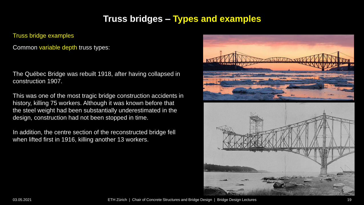
Truss bridge examples
Common variable depth truss types:
The Québec Bridge was rebuilt 1918, after having collapsed in
construction 1907.
This was one of the most tragic bridge construction accidents in
history, killing 75 workers. Although it was known before that
the steel weight had been substantially underestimated in the
design, construction had not been stopped in time.
In addition, the centre section of the reconstructed bridge fell
when lifted first in 1916, killing another 13 workers.

Truss bridges – Types and examples
03.05.2021 20ETH Zürich | Chair of Concrete Structures and Bridge Design | Bridge Design Lectures
Truss bridge examples
Uncommon yet interesting truss types:
• Fink truss / Fink’scher Träger: Multiple overlapping diagonal
members and vertical posts (puente de Fierro / Bolívar,
1882).
• Inverted Fink trusses have seen a revival for footbridges
over the past years, due to their expressive character
(Frank Gehry Bridge, 2015).
Truss bridges – Types and examples
03.05.2021 21ETH Zürich | Chair of Concrete Structures and Bridge Design | Bridge Design Lectures
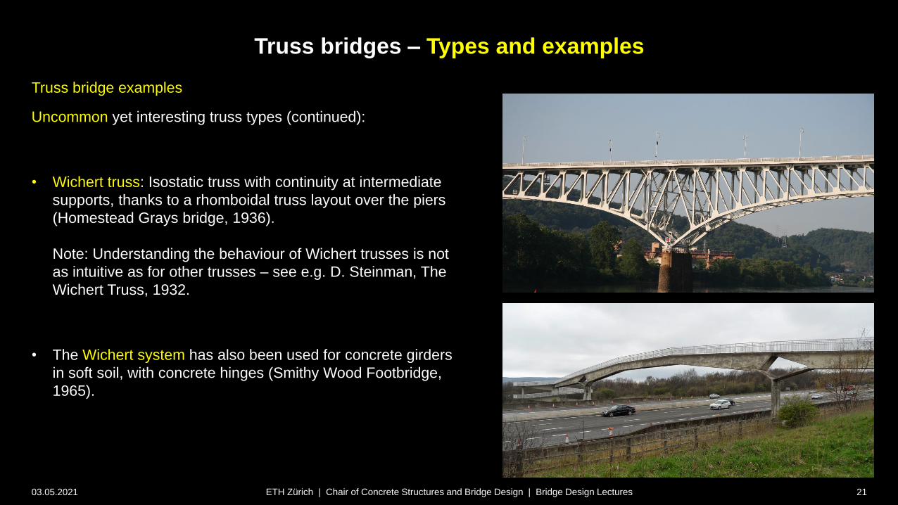
Truss bridge examples
Uncommon yet interesting truss types (continued):
• Wichert truss: Isostatic truss with continuity at intermediate
supports, thanks to a rhomboidal truss layout over the piers
(Homestead Grays bridge, 1936).
Note: Understanding the behaviour of Wichert trusses is not
as intuitive as for other trusses – see e.g. D. Steinman, The
Wichert Truss, 1932.
• The Wichert system has also been used for concrete girders
in soft soil, with concrete hinges (Smithy Wood Footbridge,
1965).
Truss bridges – Types and examples
03.05.2021 22ETH Zürich | Chair of Concrete Structures and Bridge Design | Bridge Design Lectures
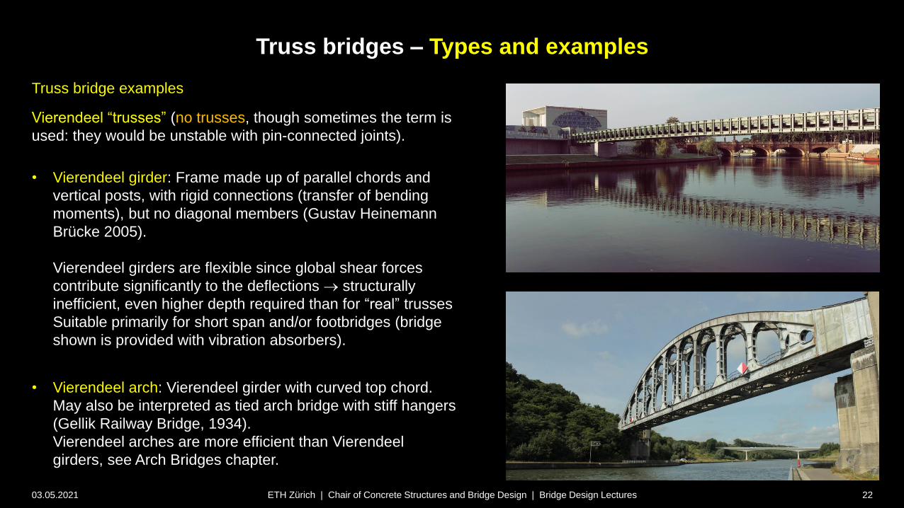
Truss bridge examples
Vierendeel “trusses” (no trusses, though sometimes the term is
used: they would be unstable with pin-connected joints).
• Vierendeel girder: Frame made up of parallel chords and
vertical posts, with rigid connections (transfer of bending
moments), but no diagonal members (Gustav Heinemann
Brücke 2005).
Vierendeel girders are flexible since global shear forces
contribute significantly to the deflections structurally
inefficient, even higher depth required than for “real” trusses
Suitable primarily for short span and/or footbridges (bridge
shown is provided with vibration absorbers).
• Vierendeel arch: Vierendeel girder with curved top chord.
May also be interpreted as tied arch bridge with stiff hangers
(Gellik Railway Bridge, 1934).
Vierendeel arches are more efficient than Vierendeel
girders, see Arch Bridges chapter.

Truss bridges – Types and examples
03.05.2021 23ETH Zürich | Chair of Concrete Structures and Bridge Design | Bridge Design Lectures
Truss bridge examples
Tubular steel trusses minimise many of the
disadvantages mentioned in the previous section, and
have seen a revival in the last years thanks to recent
developments. Such trusses have several advantages:
• modern sleek appearance
• smaller exposed surface (compared to other trusses)
• high member inertia (slender compression members
possible higher transparency)
Swiss Engineer Hans-Gerhard Dauner (1937-2007,
founder of DIC Ingénieurs at Aigle) was a pioneer in
these developments.
(Note that tubular members were already used in the
19th century, e.g. Firth of Forth, but construction was
highly complicated particularly for the joints).

Truss bridges – Types and examples
03.05.2021 24ETH Zürich | Chair of Concrete Structures and Bridge Design | Bridge Design Lectures
Truss bridge examples
The efficiency of tubular steel-concrete composite
truss bridges can be further enhanced using
concrete for both chords, combined with
prestressing.
Mainly in France, several impressive bridges
using this technology, with external prestressing
tendons, were built in the 1990s.
Note that proper corrosion protection of the
external tendons is essential for the durability of
such bridges (several of the bridges built in the
1990s had to be repaired after 30 years of service
due to improper grouting of the tendons).
Truss bridges – Types and examples
03.05.2021 25ETH Zürich | Chair of Concrete Structures and Bridge Design | Bridge Design Lectures
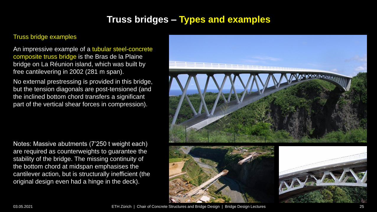
Truss bridge examples
An impressive example of a tubular steel-concrete
composite truss bridge is the Bras de la Plaine
bridge on La Réunion island, which was built by
free cantilevering in 2002 (281 m span).
No external prestressing is provided in this bridge,
but the tension diagonals are post-tensioned (and
the inclined bottom chord transfers a significant
part of the vertical shear forces in compression).
Notes: Massive abutments (7’250 t weight each)
are required as counterweights to guarantee the
stability of the bridge. The missing continuity of
the bottom chord at midspan emphasises the
cantilever action, but is structurally inefficient (the
original design even had a hinge in the deck).

Truss bridges – Types and examples
03.05.2021 26ETH Zürich | Chair of Concrete Structures and Bridge Design | Bridge Design Lectures
Truss bridge examples
Concrete trusses have also been used in bridges to
save weight.
Using prefabricated ultra-high performance concrete
elements, slender truss elements are possible.
(top photos: Viaduc de Glacières 1989). Nonetheless,
achieving transparency is difficult.
Cast-in situ concrete trusses (with post-tensioned
tension diagonals) tend to appear even heavier, making
the choice of material difficult to justify: Why not use
steel struts here?

Truss bridges – Types and examples
03.05.2021 27ETH Zürich | Chair of Concrete Structures and Bridge Design | Bridge Design Lectures
Truss bridge examples
An aesthetically convincing concrete truss bridge is the
Ponte Mosteirô, by the eminent Portuguese engineer
Edgar Cardoso (designer of the more famous Ponte da
Arrabida).
Truss bridges – Types and examples
03.05.2021 28ETH Zürich | Chair of Concrete Structures and Bridge Design | Bridge Design Lectures
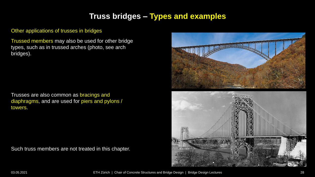
Other applications of trusses in bridges
Trussed members may also be used for other bridge
types, such as in trussed arches (photo, see arch
bridges).
Trusses are also common as bracings and
diaphragms, and are used for piers and pylons /
towers.
Such truss members are not treated in this chapter.

Special girder bridges
03.05.2021 29
Truss bridges
Design
ETH Zürich | Chair of Concrete Structures and Bridge Design | Bridge Design Lectures
Truss bridges – Design
03.05.2021 30ETH Zürich | Chair of Concrete Structures and Bridge Design | Bridge Design Lectures
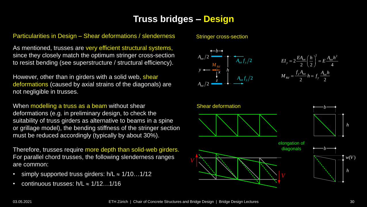
Particularities in Design – Shear deformations / slenderness
As mentioned, trusses are very efficient structural systems,
since they closely match the optimum stringer cross-section
to resist bending (see superstructure / structural efficiency).
However, other than in girders with a solid web, shear
deformations (caused by axial strains of the diagonals) are
not negligible in trusses.
When modelling a truss as a beam without shear
deformations (e.g. in preliminary design, to check the
suitability of truss girders as alternative to beams in a spine
or grillage model), the bending stiffness of the stringer section
must be reduced accordingly (typically by about 30%).
Therefore, trusses require more depth than solid-web girders.
For parallel chord trusses, the following slenderness ranges
are common:
• simply supported truss girders: h/L 1/10…1/12
• continuous trusses: h/L 1/12…1/16
2 2
22 2 4
2 2
tot toty
y tot totRd y
EA A hhEI E
f A A hM h f
Stringer cross-section
h
z
xy
b
2tot yA f
2tot yA f
RdM
2totA
2totA
Shear deformation
h
h
b
b
( )w V
V
V
elongation of
diagonals
Truss bridges – Design
03.05.2021 31ETH Zürich | Chair of Concrete Structures and Bridge Design | Bridge Design Lectures
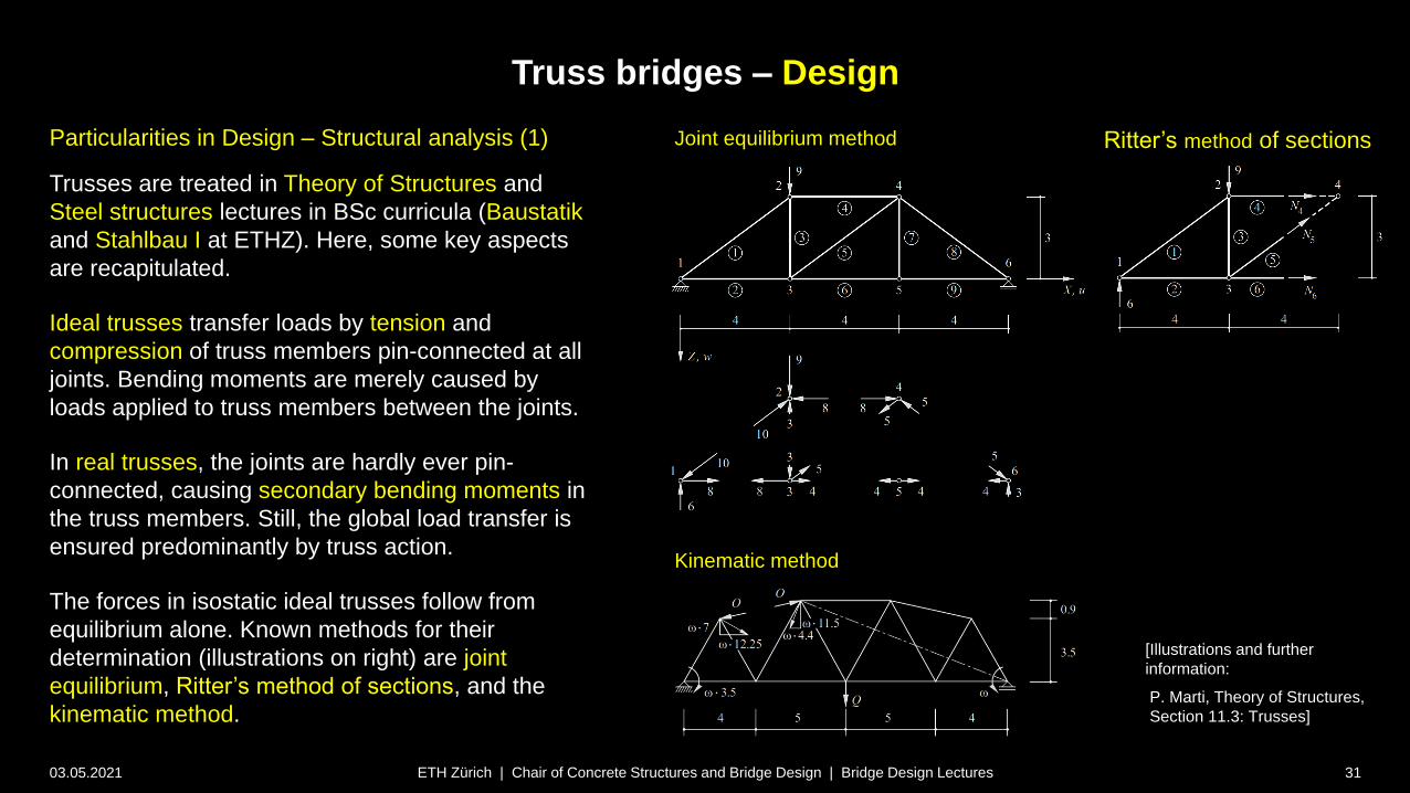
Particularities in Design – Structural analysis (1)
Trusses are treated in Theory of Structures and
Steel structures lectures in BSc curricula (Baustatik
and Stahlbau I at ETHZ). Here, some key aspects
are recapitulated.
Ideal trusses transfer loads by tension and
compression of truss members pin-connected at all
joints. Bending moments are merely caused by
loads applied to truss members between the joints.
In real trusses, the joints are hardly ever pin-
connected, causing secondary bending moments in
the truss members. Still, the global load transfer is
ensured predominantly by truss action.
The forces in isostatic ideal trusses follow from
equilibrium alone. Known methods for their
determination (illustrations on right) are joint
equilibrium, Ritter’s method of sections, and the
kinematic method.
Joint equilibrium method Ritter’s method of sections
Kinematic method
[Illustrations and further
information:
P. Marti, Theory of Structures,
Section 11.3: Trusses]
Truss bridges – Design
03.05.2021 32ETH Zürich | Chair of Concrete Structures and Bridge Design | Bridge Design Lectures
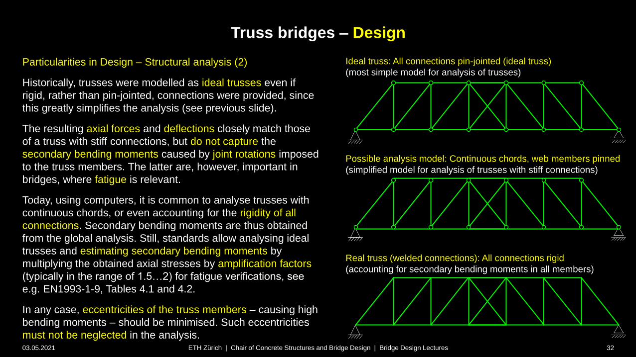
Particularities in Design – Structural analysis (2)
Historically, trusses were modelled as ideal trusses even if
rigid, rather than pin-jointed, connections were provided, since
this greatly simplifies the analysis (see previous slide).
The resulting axial forces and deflections closely match those
of a truss with stiff connections, but do not capture the
secondary bending moments caused by joint rotations imposed
to the truss members. The latter are, however, important in
bridges, where fatigue is relevant.
Today, using computers, it is common to analyse trusses with
continuous chords, or even accounting for the rigidity of all
connections. Secondary bending moments are thus obtained
from the global analysis. Still, standards allow analysing ideal
trusses and estimating secondary bending moments by
multiplying the obtained axial stresses by amplification factors
(typically in the range of 1.5…2) for fatigue verifications, see
e.g. EN1993-1-9, Tables 4.1 and 4.2.
In any case, eccentricities of the truss members – causing high
bending moments – should be minimised. Such eccentricities
must not be neglected in the analysis.
Ideal truss: All connections pin-jointed (ideal truss)
(most simple model for analysis of trusses)
Possible analysis model: Continuous chords, web members pinned
(simplified model for analysis of trusses with stiff connections)
Real truss (welded connections): All connections rigid
(accounting for secondary bending moments in all members)
Truss bridges – Design
03.05.2021 33ETH Zürich | Chair of Concrete Structures and Bridge Design | Bridge Design Lectures
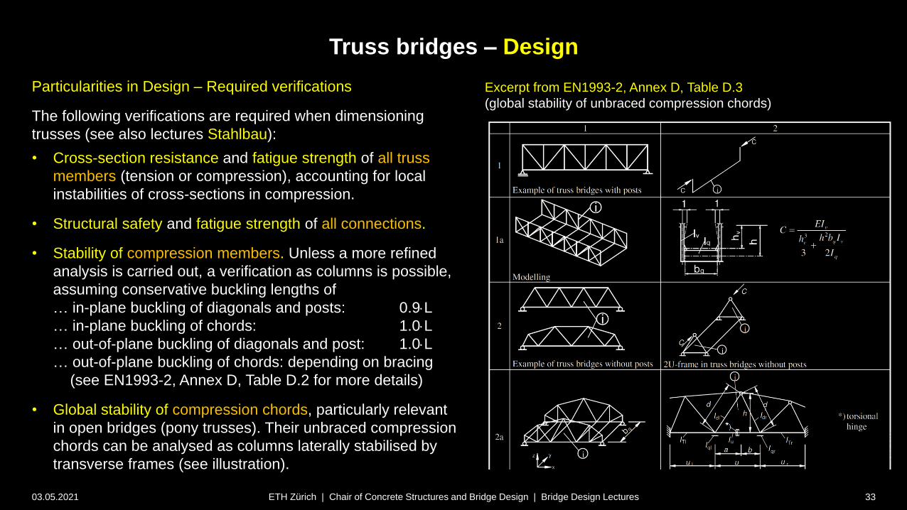
Particularities in Design – Required verifications
The following verifications are required when dimensioning
trusses (see also lectures Stahlbau):
• Cross-section resistance and fatigue strength of all truss
members (tension or compression), accounting for local
instabilities of cross-sections in compression.
• Structural safety and fatigue strength of all connections.
• Stability of compression members. Unless a more refined
analysis is carried out, a verification as columns is possible,
assuming conservative buckling lengths of
… in-plane buckling of diagonals and posts: 0.9L
… in-plane buckling of chords: 1.0L
… out-of-plane buckling of diagonals and post: 1.0L
… out-of-plane buckling of chords: depending on bracing
(see EN1993-2, Annex D, Table D.2 for more details)
• Global stability of compression chords, particularly relevant
in open bridges (pony trusses). Their unbraced compression
chords can be analysed as columns laterally stabilised by
transverse frames (see illustration).
Excerpt from EN1993-2, Annex D, Table D.3
(global stability of unbraced compression chords)

Truss bridges – Design
03.05.2021 34ETH Zürich | Chair of Concrete Structures and Bridge Design | Bridge Design Lectures
Particularities in Design – Connections
The design of the connections is essential for the structural
safety and fatigue strength of trusses. In bridges with relevant
fatigue loads – particularly railway bridges – they must be
carefully detailed to minimise stress concentrations.
Welded connections have become standard in most European
countries, and hollow sections (“tubular trusses”) are preferred
since they
• have a smaller exposed surface and a reduced tendency of
accumulating debris at the joints
• are aesthetically more appealing, particularly if gusset plates
are avoided
Corrosion protection on the inside of hollow sections is achieved
by airtight sealing. This can hardly be achieved with bolted
connections, since even small gaps (pinholes) may be sufficient
to cause harmful humidity inside the cross-sections, that
“breathe” under temperature variation. Therefore, tubular trusses
are less popular in North America, where bolted connections are
favoured.
Truss bridges – Design
03.05.2021 35ETH Zürich | Chair of Concrete Structures and Bridge Design | Bridge Design Lectures
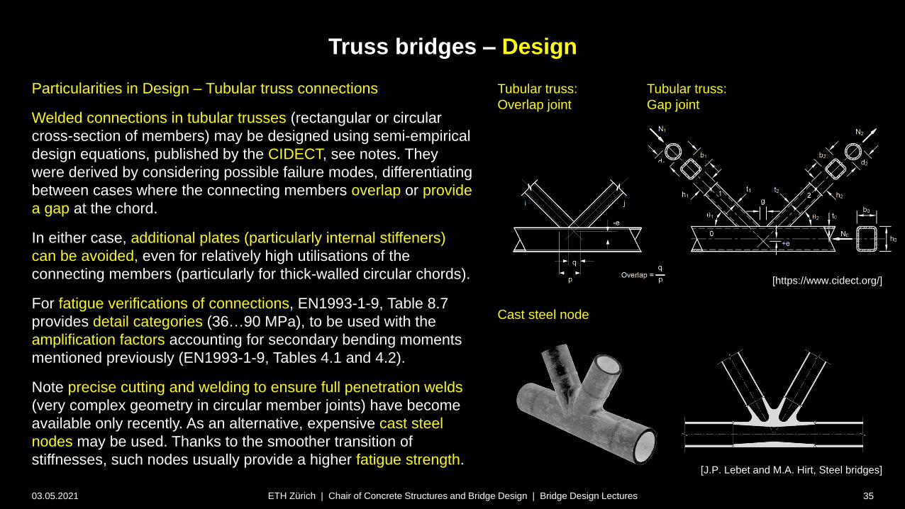
Particularities in Design – Tubular truss connections
Welded connections in tubular trusses (rectangular or circular
cross-section of members) may be designed using semi-empirical
design equations, published by the CIDECT, see notes. They
were derived by considering possible failure modes, differentiating
between cases where the connecting members overlap or provide
a gap at the chord.
In either case, additional plates (particularly internal stiffeners)
can be avoided, even for relatively high utilisations of the
connecting members (particularly for thick-walled circular chords).
For fatigue verifications of connections, EN1993-1-9, Table 8.7
provides detail categories (36…90 MPa), to be used with the
amplification factors accounting for secondary bending moments
mentioned previously (EN1993-1-9, Tables 4.1 and 4.2).
Note precise cutting and welding to ensure full penetration welds
(very complex geometry in circular member joints) have become
available only recently. As an alternative, expensive cast steel
nodes may be used. Thanks to the smoother transition of
stiffnesses, such nodes usually provide a higher fatigue strength.
Tubular truss:
Gap joint
Tubular truss:
Overlap joint
[https://www.cidect.org/]
Cast steel node
[J.P. Lebet and M.A. Hirt, Steel bridges]
Truss bridges – Design
03.05.2021 36ETH Zürich | Chair of Concrete Structures and Bridge Design | Bridge Design Lectures
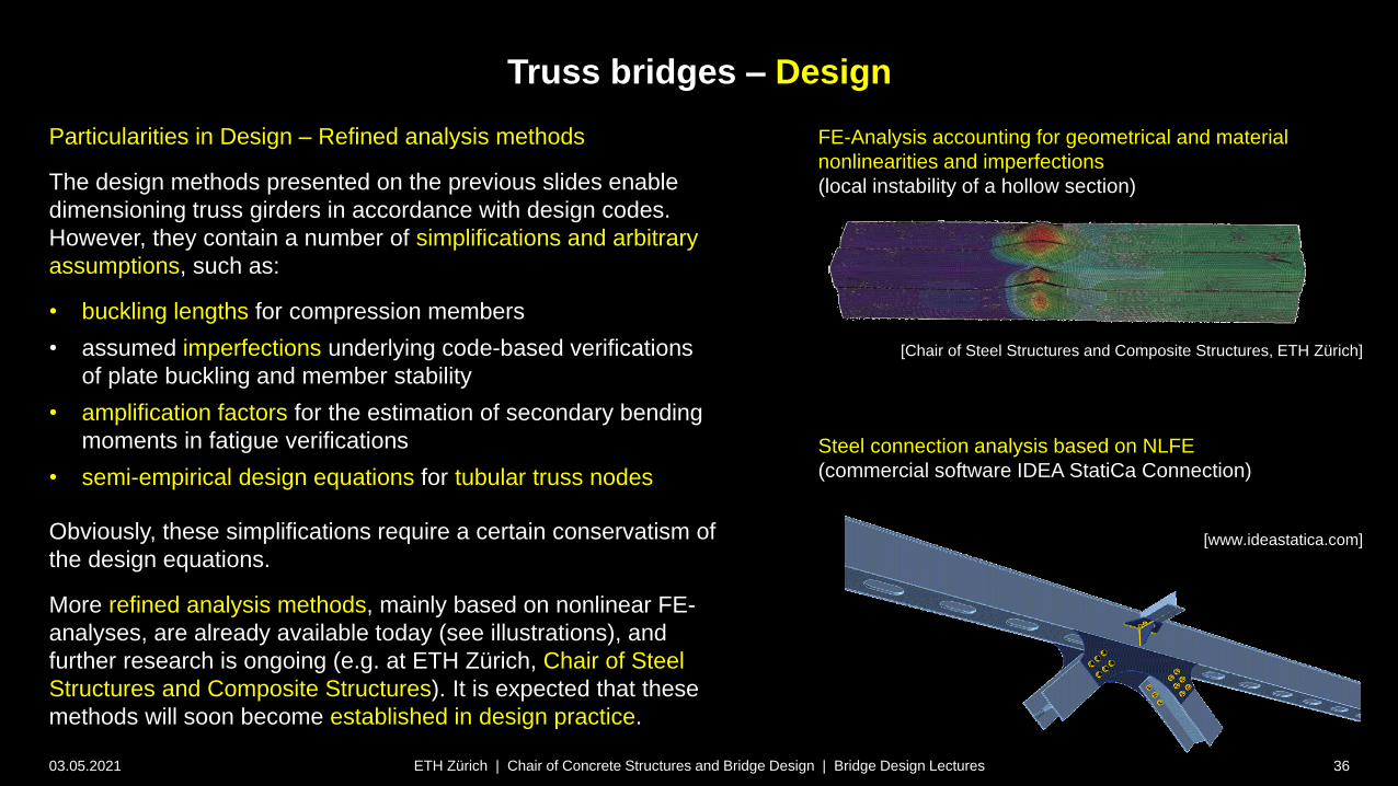
Particularities in Design – Refined analysis methods
The design methods presented on the previous slides enable
dimensioning truss girders in accordance with design codes.
However, they contain a number of simplifications and arbitrary
assumptions, such as:
• buckling lengths for compression members
• assumed imperfections underlying code-based verifications
of plate buckling and member stability
• amplification factors for the estimation of secondary bending
moments in fatigue verifications
• semi-empirical design equations for tubular truss nodes
Obviously, these simplifications require a certain conservatism of
the design equations.
More refined analysis methods, mainly based on nonlinear FE-
analyses, are already available today (see illustrations), and
further research is ongoing (e.g. at ETH Zürich, Chair of Steel
Structures and Composite Structures). It is expected that these
methods will soon become established in design practice.
FE-Analysis accounting for geometrical and material
nonlinearities and imperfections
(local instability of a hollow section)
[www.ideastatica.com]
Steel connection analysis based on NLFE
(commercial software IDEA StatiCa Connection)
[Chair of Steel Structures and Composite Structures, ETH Zürich]