ts 123 231 - v14.0.0 - digital cellular telecommunications ... · pdf fileetsi 3gpp ts 23.231...
TRANSCRIPT

ETSI TS 123 231 V14.0.0 (2017-04)
Digital cellular telecommunications system (Phase 2+) (GSM); Universal Mobile Telecommunications System (UMTS);
SIP-I based circuit-switched core network; Stage 2
(3GPP TS 23.231 version 14.0.0 Release 14)
TECHNICAL SPECIFICATION
GLOBAL SYSTEM FOR MOBILE COMMUNICATIONS
R

ETSI
ETSI TS 123 231 V14.0.0 (2017-04)13GPP TS 23.231 version 14.0.0 Release 14
Reference RTS/TSGC-0423231ve00
Keywords GSM,UMTS
ETSI
650 Route des Lucioles F-06921 Sophia Antipolis Cedex - FRANCE
Tel.: +33 4 92 94 42 00 Fax: +33 4 93 65 47 16
Siret N° 348 623 562 00017 - NAF 742 C
Association à but non lucratif enregistrée à la Sous-Préfecture de Grasse (06) N° 7803/88
Important notice
The present document can be downloaded from: http://www.etsi.org/standards-search
The present document may be made available in electronic versions and/or in print. The content of any electronic and/or print versions of the present document shall not be modified without the prior written authorization of ETSI. In case of any
existing or perceived difference in contents between such versions and/or in print, the only prevailing document is the print of the Portable Document Format (PDF) version kept on a specific network drive within ETSI Secretariat.
Users of the present document should be aware that the document may be subject to revision or change of status. Information on the current status of this and other ETSI documents is available at
https://portal.etsi.org/TB/ETSIDeliverableStatus.aspx
If you find errors in the present document, please send your comment to one of the following services: https://portal.etsi.org/People/CommiteeSupportStaff.aspx
Copyright Notification
No part may be reproduced or utilized in any form or by any means, electronic or mechanical, including photocopying and microfilm except as authorized by written permission of ETSI.
The content of the PDF version shall not be modified without the written authorization of ETSI. The copyright and the foregoing restriction extend to reproduction in all media.
© European Telecommunications Standards Institute 2017.
All rights reserved.
DECTTM, PLUGTESTSTM, UMTSTM and the ETSI logo are Trade Marks of ETSI registered for the benefit of its Members. 3GPPTM and LTE™ are Trade Marks of ETSI registered for the benefit of its Members and
of the 3GPP Organizational Partners. GSM® and the GSM logo are Trade Marks registered and owned by the GSM Association.

ETSI
ETSI TS 123 231 V14.0.0 (2017-04)23GPP TS 23.231 version 14.0.0 Release 14
Intellectual Property Rights IPRs essential or potentially essential to the present document may have been declared to ETSI. The information pertaining to these essential IPRs, if any, is publicly available for ETSI members and non-members, and can be found in ETSI SR 000 314: "Intellectual Property Rights (IPRs); Essential, or potentially Essential, IPRs notified to ETSI in respect of ETSI standards", which is available from the ETSI Secretariat. Latest updates are available on the ETSI Web server (https://ipr.etsi.org/).
Pursuant to the ETSI IPR Policy, no investigation, including IPR searches, has been carried out by ETSI. No guarantee can be given as to the existence of other IPRs not referenced in ETSI SR 000 314 (or the updates on the ETSI Web server) which are, or may be, or may become, essential to the present document.
Foreword This Technical Specification (TS) has been produced by the ETSI 3rd Generation Partnership Project (3GPP).
The present document may refer to technical specifications or reports using their 3GPP identities, UMTS identities or GSM identities. These should be interpreted as being references to the corresponding ETSI deliverables.
The cross reference between GSM, UMTS, 3GPP and ETSI identities can be found under http://webapp.etsi.org/key/queryform.asp.
Modal verbs terminology In the present document "shall", "shall not", "should", "should not", "may", "need not", "will", "will not", "can" and "cannot" are to be interpreted as described in clause 3.2 of the ETSI Drafting Rules (Verbal forms for the expression of provisions).
"must" and "must not" are NOT allowed in ETSI deliverables except when used in direct citation.

ETSI
ETSI TS 123 231 V14.0.0 (2017-04)33GPP TS 23.231 version 14.0.0 Release 14
Contents
Intellectual Property Rights ................................................................................................................................ 2
Foreword ............................................................................................................................................................. 2
Modal verbs terminology .................................................................................................................................... 2
Foreword ............................................................................................................................................................. 8
1 Scope ........................................................................................................................................................ 9
2 References ................................................................................................................................................ 9
3 Definitions, symbols and abbreviations ................................................................................................. 10
3.1 Definitions ........................................................................................................................................................ 10
3.2 Symbols ............................................................................................................................................................ 10
3.3 Abbreviations ................................................................................................................................................... 11
4 Main Concepts ........................................................................................................................................ 11
4.1 General ............................................................................................................................................................. 11
4.2 Call Control ...................................................................................................................................................... 12
4.3 H.248 ................................................................................................................................................................ 12
4.4 MGW Selection ................................................................................................................................................ 12
4.4.1 Principles .................................................................................................................................................... 12
4.4.2 Optimised MGW Selection ......................................................................................................................... 12
4.4.3 Deferred MGW selection ............................................................................................................................ 14
4.4.4 Mobile to Mobile Call................................................................................................................................. 15
4.4.5 MGW bypass .............................................................................................................................................. 16
5 General Circuit Switched Core Network Domain Architecture ............................................................. 18
6 Call Establishment .................................................................................................................................. 19
6.1 Basic Mobile Originating Call.......................................................................................................................... 19
6.1.1 Basic Mobile Originating Call Establishment with immediate MGW selection ........................................ 19
6.1.1.1 General .................................................................................................................................................. 19
6.1.1.2 MGW selection ..................................................................................................................................... 19
6.1.1.3 Initial INVITE message ........................................................................................................................ 19
6.1.1.4 Network side bearer establishment ....................................................................................................... 19
6.1.1.5 Access bearer assignment ..................................................................................................................... 20
6.1.1.6 Framing protocol initialisation .............................................................................................................. 20
6.1.1.7 Through-Connection ............................................................................................................................. 20
6.1.1.8 Confirmation of bearer establishment ................................................................................................... 20
6.1.1.9 Interworking function............................................................................................................................ 20
6.1.1.10 Codec handling ..................................................................................................................................... 20
6.1.1.11 Voice Processing function ..................................................................................................................... 20
6.1.1.12 Failure handling in MSC server ............................................................................................................ 20
6.1.1.13 Example ................................................................................................................................................ 21
6.1.2 Originating Call Establishment For Iu Interface on IP with immediate MGW selection ........................... 23
6.1.3 Originating Call Establishment For A Interface user plane over IP with immediate MGW selection........ 24
6.2 Basic Mobile Terminating Call ........................................................................................................................ 25
6.2.1 Basic Mobile Terminating Call Establishment with immediate MGW selection ....................................... 25
6.2.1.1 General .................................................................................................................................................. 25
6.2.1.2 GMSC server......................................................................................................................................... 26
6.2.1.2.1 MGW selection ................................................................................................................................ 26
6.2.1.2.2 Initial INVITE message ................................................................................................................... 26
6.2.1.2.3 Outgoing side bearer termination configuration .............................................................................. 26
6.2.1.2.4 Incoming side bearer termination configuration .............................................................................. 26
6.2.1.2.5 Through-Connection ........................................................................................................................ 26
6.2.1.2.6 Indication of bearer establishment ................................................................................................... 26
6.2.1.2.7 Voice Processing function ............................................................................................................... 27
6.2.1.2.8 Failure handling in GMSC server .................................................................................................... 27
6.2.1.3 MSC server ........................................................................................................................................... 27

ETSI
ETSI TS 123 231 V14.0.0 (2017-04)43GPP TS 23.231 version 14.0.0 Release 14
6.2.1.3.1 Paging .............................................................................................................................................. 27
6.2.1.3.2 Call setup ......................................................................................................................................... 27
6.2.1.3.3 MGW selection ................................................................................................................................ 27
6.2.1.3.4 Network side bearer termination configuration ............................................................................... 28
6.2.1.3.5 Access bearer assignment ................................................................................................................ 28
6.2.1.3.6 Framing protocol initialisation ........................................................................................................ 28
6.2.1.3.7 Called party alerting ........................................................................................................................ 28
6.2.1.3.8 Called party answer ......................................................................................................................... 28
6.2.1.3.9 Through-Connection ........................................................................................................................ 28
6.2.1.3.10 Interworking function ...................................................................................................................... 29
6.2.1.3.11 Codec handling ................................................................................................................................ 29
6.2.1.3.12 Voice Processing function ............................................................................................................... 29
6.2.1.3.13 Failure handling in MSC server ....................................................................................................... 29
6.2.1.3.14 Example - the GMSC selects a MGW ............................................................................................. 29
6.2.2 Terminating Call Establishment For Iu Interface on IP with immediate MGW selection .......................... 32
6.2.3 Terminating Call Establishment For A Interface user plane over IP with immediate MGW selection ...... 32
7 Call Clearing .......................................................................................................................................... 33
7.1 General ............................................................................................................................................................. 33
7.2 Visited MSC Server Procedures ....................................................................................................................... 34
7.2.1 Call Clearing when Visited MSC Server has Forwarded/Deflected Call ................................................... 34
7.2.2 Call Clearing received from core network .................................................................................................. 34
7.2.2.1 Procedures towards access side ............................................................................................................. 34
7.2.2.2 Procedures towards network side .......................................................................................................... 34
7.2.2.2.1 Call Clearing during establishment ................................................................................................. 34
7.2.2.2.1.1 Originating MSC-S .................................................................................................................... 34
7.2.2.2.1.2 Terminating MSC-S ................................................................................................................... 34
7.2.2.2.2 Call Clearing after call established .................................................................................................. 34
7.2.2.2.2.1 Originating MSC-S .................................................................................................................... 34
7.2.2.2.2.2 Terminating MSC-S ................................................................................................................... 35
7.2.2.3 Example Call Flow ................................................................................................................................ 35
7.2.3 Call Clearing received from UE ................................................................................................................. 36
7.2.3.1 Procedures towards access side ............................................................................................................. 36
7.2.3.2 Procedures towards network side .......................................................................................................... 37
7.2.3.2.1 Call Clearing during call establishment ........................................................................................... 37
7.2.3.2.1.1 Originating MSC-S .................................................................................................................... 37
7.2.3.2.1.2 Terminating MSC-S ................................................................................................................... 37
7.2.3.2.2 Call Clearing after call established .................................................................................................. 37
7.2.3.2.2.1 Originating MSC-S .................................................................................................................... 37
7.2.3.2.2.2 Terminating MSC-S ................................................................................................................... 37
7.2.3.3 Example Call Flow ................................................................................................................................ 37
7.2.4 Call Clearing initiated by V-MSC Server ................................................................................................... 39
7.2.4.1 Call clearing towards access network ................................................................................................... 39
7.2.4.2 Call clearing towards network side ....................................................................................................... 39
7.2.4.3 Example Call Flow ................................................................................................................................ 39
7.2.5 Call clearing received from MGW ............................................................................................................. 40
7.2.5.1 Bearer released on the access side ......................................................................................................... 40
7.2.5.2 Bearer released on the network side ...................................................................................................... 40
7.2.5.3 Example Call Flow ................................................................................................................................ 40
7.2.6 Call Clearing procedures towards MGW .................................................................................................... 42
7.2.7 Call Clearing for Iu Interface on IP ............................................................................................................ 42
7.3 Gateway MSC Server Procedures .................................................................................................................... 42
7.3.1 Call Clearing received from peer SIP-I node .............................................................................................. 42
7.3.2 Call Clearing initiated by G-MSC Server ................................................................................................... 43
7.3.2.1 Call clearing to the destination side ...................................................................................................... 43
7.3.2.2 Call clearing to the originating side ...................................................................................................... 43
7.3.3 Call Clearing received from MGW ............................................................................................................. 43
7.3.3.1 Bearer released on the destination side ................................................................................................. 43
7.3.3.2 Bearer released on the originating side ................................................................................................. 43
7.3.4 Call Clearing procedures towards MGW .................................................................................................... 44
8 Handover/Relocation .............................................................................................................................. 44

ETSI
ETSI TS 123 231 V14.0.0 (2017-04)53GPP TS 23.231 version 14.0.0 Release 14
8.1 UMTS to UMTS ............................................................................................................................................... 44
8.1.1 Intra-MSC SRNS/SBSS Relocation ........................................................................................................... 44
8.1.1.1 Intra-MGW Relocation ......................................................................................................................... 44
8.1.1.2 Inter-MGW Relocation ......................................................................................................................... 44
8.1.2 Basic Inter-MSC SRNS/SBSS Relocation .................................................................................................. 44
8.1.3 Subsequent Inter-MSC SRNS/SBSS Relocation back to the Anchor MSC ............................................... 44
8.1.4 Subsequent Inter-MSC SRNS/SBSS Relocation to a third MSC ............................................................... 44
8.1.5 SRNS/SBSS Relocation with Iu on IP ........................................................................................................ 45
8.2 UMTS to GSM ................................................................................................................................................. 45
8.2.1 Intra-MSC UMTS to GSM Handover ......................................................................................................... 45
8.2.1.1 Intra-MGW Relocation ......................................................................................................................... 45
8.2.1.2 Inter-MGW Relocation ......................................................................................................................... 45
8.2.1.3 Intra-MSC UMTS to GSM Handover for A interface over IP .............................................................. 45
8.2.2 Basic Inter-MSC UMTS to GSM Handover ............................................................................................... 45
8.2.2.1 Basic Inter-MSC UMTS to GSM Handover for A Interface over IP .................................................... 45
8.2.3 Subsequent Inter-MSC UMTS to GSM Handover back to the Anchor MSC ............................................. 45
8.2.3.1 Subsequent Inter-MSC UMTS to GSM Handover back to the anchor MSC for A Interface over IP ........................................................................................................................................................... 45
8.2.4 Subsequent Inter-MSC UMTS to GSM Handover to a third MSC ............................................................. 46
8.3 GSM to UMTS ................................................................................................................................................. 46
8.3.1 Intra-MSC GSM to UMTS Handover ......................................................................................................... 46
8.3.1.1 Intra-MGW Relocation ......................................................................................................................... 46
8.3.1.2 Inter-MGW Relocation ......................................................................................................................... 46
8.3.2 Basic Inter-MSC GSM to UMTS Handover ............................................................................................... 46
8.3.3 Subsequent Inter-MSC GSM to UMTS Handover back to the Anchor MSC ............................................. 46
8.3.4 Subsequent Inter-MSC GSM to UMTS Handover to a third MSC ............................................................. 46
8.3.5 GSM to UMTS Handover with Iu on IP ..................................................................................................... 46
8.4 GSM to GSM ................................................................................................................................................... 47
8.4.1 Intra-MSC Inter-BSS GSM to GSM Handover .......................................................................................... 47
8.4.1.1 Intra-MGW Relocation ......................................................................................................................... 47
8.4.1.2 Inter-MGW Relocation ......................................................................................................................... 47
8.4.1.3 Intra-MSC GSM to GSM Handover for A interface over IP ................................................................ 47
8.4.2 Basic Inter-MSC GSM to GSM Handover ................................................................................................. 47
8.4.2.1 Basic Inter-MSC GSM to GSM Handover for A Interface over IP ...................................................... 47
8.4.3 Subsequent Inter-MSC GSM to GSM Handover back to the Anchor MSC ............................................... 47
8.4.3.1 Subsequent Inter-MSC GSM to GSM Handover back to the anchor MSC for A Interface over IP ..... 47
8.4.4 Subsequent GSM to GSM Handover to a third MSC ................................................................................. 47
8.4.5 BSS Internal Handover ............................................................................................................................... 48
9 Compatibility Issues ............................................................................................................................... 48
9.1 Compatibility Issues for Nc Interface ............................................................................................................... 48
9.2 Compatibility Issues for Mc Interface .............................................................................................................. 48
10 General (G)MSC server-MGW Procedures ........................................................................................... 48
10.1 MGW Unavailable ........................................................................................................................................... 48
10.2 MGW Available ............................................................................................................................................... 48
10.3 MGW Recovery ............................................................................................................................................... 48
10.4 (G)MSC server Recovery ................................................................................................................................. 48
10.5 MGW Re-register ............................................................................................................................................. 48
10.6 MGW Re-registration Ordered by (G)MSC server .......................................................................................... 48
10.7 Removal from Service of a Physical Termination ............................................................................................ 48
10.8 Restoration to Service of a Physical Termination ............................................................................................ 49
10.9 Audit of MGW ................................................................................................................................................. 49
10.10 MGW Capability Change ................................................................................................................................. 49
10.11 (G)MSC Server Out of service ......................................................................................................................... 49
10.12 MGW Resource Congestion Handling - Activate ............................................................................................ 49
10.13 MGW Resource Congestion Handling -Indication ........................................................................................... 49
10.14 Control association monitoring ........................................................................................................................ 49
10.15 Hanging termination detection ......................................................................................................................... 49
11 Identities ................................................................................................................................................. 49
11.1 Telephone numbering schemes ........................................................................................................................ 49
11.2 (G)MSC Server Identity ................................................................................................................................... 49
ETSI
ETSI TS 123 231 V14.0.0 (2017-04)63GPP TS 23.231 version 14.0.0 Release 14
11.3 Sub-addressing ................................................................................................................................................. 49
12 Operational Aspects ............................................................................................................................... 50
12.1 Charging ........................................................................................................................................................... 50
12.2 SIP session continuity ...................................................................................................................................... 50
12.2.1 Use of SIP session timer ............................................................................................................................. 50
12.2.2 Example call flow ....................................................................................................................................... 50
13 Interactions with Other Services ............................................................................................................ 51
13.1 Enhanced Multi-Level Precedence and Pre-emption service (eMLPP)............................................................ 51
13.2 Call Deflection Service .................................................................................................................................... 51
13.3 Line identification Services .............................................................................................................................. 51
13.3.1 Calling Line Identification Presentation (CLIP) ......................................................................................... 51
13.3.2 Calling Line Identification Restriction (CLIR) ........................................................................................... 51
13.3.3 Connected Line Identification Presentation (COLP) .................................................................................. 52
13.3.4 Connected Line Identification Restriction (COLR) .................................................................................... 52
13.4 Call Forwarding Services ................................................................................................................................. 52
13.4.0 Principles .................................................................................................................................................... 52
13.4.1 Call Forwarding Unconditional (CFU) ....................................................................................................... 52
13.4.2 Call Forwarding on mobile subscriber Busy (CFB) ................................................................................... 52
13.4.2.1 Network Determined User Busy (NDUB) ............................................................................................ 52
13.4.2.1.1 Initial INVITE ................................................................................................................................. 52
13.4.2.1.2 Confirmation of bearer establishment ............................................................................................. 52
13.4.2.2 User Determined User Busy (UDUB) ................................................................................................... 53
13.4.2.2.1 Initial INVITE ................................................................................................................................. 53
13.4.2.2.2 Confirmation of bearer establishment ............................................................................................. 53
13.4.3 Call Forwarding on No Reply (CFNRy) ..................................................................................................... 53
13.4.3.1 Initial INVITE ....................................................................................................................................... 53
13.4.4 Call Forwarding on mobile subscriber Not Reachable (CFNRc)................................................................ 54
13.4.4.1 Initial INVITE ....................................................................................................................................... 54
13.4.4.2 Confirmation of bearer establishment ................................................................................................... 54
13.5 Call Waiting (CW) ........................................................................................................................................... 54
13.6 Call Hold (CH) ................................................................................................................................................. 54
13.6.1 Principles .................................................................................................................................................... 54
13.6.2 Hold Request .............................................................................................................................................. 54
13.6.3 Retrieval Request ........................................................................................................................................ 55
13.7 Multiparty (MPTY) .......................................................................................................................................... 55
13.7.1 Introduction................................................................................................................................................. 55
13.7.2 Beginning the Multi Party call .................................................................................................................... 55
13.7.3 Managing an active Multi Party call ........................................................................................................... 56
13.7.4 Disconnect .................................................................................................................................................. 56
13.7.5 Failure handling in MSC server .................................................................................................................. 56
13.7.6 Example 1 ................................................................................................................................................... 56
13.8 Closed User Group (CUG) ............................................................................................................................... 58
13.9 Advice of Charge (AoC) .................................................................................................................................. 58
13.10 User-to-User Signalling (UUS) ........................................................................................................................ 59
13.11 Call Barring Services ........................................................................................................................................ 59
13.11.1 Barring of outgoing calls ............................................................................................................................ 59
13.11.2 Barring of incoming calls other than Anonymous Call Rejection .............................................................. 59
13.11.3 Anonymous Call Rejection (ACR) ............................................................................................................. 59
13.12 Explicit Call Transfer (ECT) ............................................................................................................................ 59
13.12.1 Example ...................................................................................................................................................... 59
13.13 Completion of Calls to Busy Subscriber (CCBS)............................................................................................. 60
13.14 Multiple Subscriber Profile (MSP) ................................................................................................................... 60
13.15 Multicall ........................................................................................................................................................... 60
13.16 Calling Name Presentation (CNAP) ................................................................................................................. 60
13.17 Alternate Speech/Fax ....................................................................................................................................... 60
13.18 Modification of the Access Bearer ................................................................................................................... 61
13.18.1 Modification of Bearer Characteristics ....................................................................................................... 61
13.18.2 IWF Protocol Change ................................................................................................................................. 61
13.19 GSM Fax .......................................................................................................................................................... 61
13.20 Voice group call service (VGCS), Voice broadcast service (VBS) .................................................................. 61

ETSI
ETSI TS 123 231 V14.0.0 (2017-04)73GPP TS 23.231 version 14.0.0 Release 14
14 Interactions with Other Network Features and Services ........................................................................ 61
14.1 Customised Applications for Mobile network Enhanced Logic (CAMEL) ..................................................... 61
14.1.1 Play Announcement/Send Tone .................................................................................................................. 61
14.1.2 User Interaction .......................................................................................................................................... 62
14.1.3 Call Party Handling (CPH) ......................................................................................................................... 62
14.2 IST .................................................................................................................................................................... 62
14.3 Operator Determined Barring (ODB) ............................................................................................................... 62
14.4 DTMF ............................................................................................................................................................... 62
14.4.1 General ........................................................................................................................................................ 62
14.4.2 DTMF handling in SIP-I Offer/Answer ...................................................................................................... 63
14.4.3 Server to MGW Procedures ........................................................................................................................ 63
14.4.4 RTP Telephony Event DTMF Digit Generation ......................................................................................... 64
14.4.4.1 General .................................................................................................................................................. 64
14.4.4.2 Start DTMF ........................................................................................................................................... 64
14.4.4.3 Stop DTMF ........................................................................................................................................... 64
14.4.4.4 Example ................................................................................................................................................ 64
14.4.5 DTMF Tone Generation ............................................................................................................................. 64
14.4.6 RTP Telephony Event DTMF Digit Detection ........................................................................................... 65
14.4.6.1 General .................................................................................................................................................. 65
14.4.6.2 Detect DTMF Digit ............................................................................................................................... 65
14.4.6.3 Example – DTMF Notification ............................................................................................................ 65
14.4.7 Inband DTMF Tone Detection.................................................................................................................... 66
14.4.8 Interworking between RTP Telephony Events and Inband DTMF Tones .................................................. 66
14.5 OR .................................................................................................................................................................... 67
14.6 Providing tones or announcements ................................................................................................................... 67
14.6.1 Introduction................................................................................................................................................. 67
14.6.2 Preconditions when providing in-band information to the calling subscriber ............................................ 67
14.6.3 Preconditions when providing in-band information to the called subscriber .............................................. 68
14.6.4 Preconditions when providing in-band information to multiple subscribers .............................................. 68
14.6.5 Request to play an announcement/tone ....................................................................................................... 68
14.6.6 Stopping an announcement/tone ................................................................................................................. 68
14.6.7 Announcement/tone completed .................................................................................................................. 68
14.7 Global Text Telephony ..................................................................................................................................... 68
14.8 Emergency Calls .............................................................................................................................................. 68
14.9 Subscriber and equipment trace ........................................................................................................................ 68
14.10 Customized Alerting Tones .............................................................................................................................. 68
14.10.1 General ........................................................................................................................................................ 68
14.10.2 Audio CAT ................................................................................................................................................. 69
14.10.3 Multimedia CAT ......................................................................................................................................... 69
15 Messages/Procedures and their contents ................................................................................................ 69
15.1 Messages between (G)MSC servers ................................................................................................................. 69
15.2 Procedures between (G)MSC server and MGW .............................................................................................. 69
15.2.1 Generic Mc Interface Procedures ................................................................................................................ 69
15.2.2 SIP-I Specific Mc Interface Procedures ...................................................................................................... 72
16 Bearer Redirect ....................................................................................................................................... 72
17 (G)MSC MGW Tandeming .................................................................................................................... 72
18 Timers for SIP-I based CS core network ................................................................................................ 73
19 Multiple IP Realms ................................................................................................................................. 73
Annex A (informative): Change history ............................................................................................... 74
History .............................................................................................................................................................. 75
ETSI
ETSI TS 123 231 V14.0.0 (2017-04)83GPP TS 23.231 version 14.0.0 Release 14
Foreword This Technical Specification (TS) has been produced by ETSI 3rd Generation Partnership Project (3GPP).
The contents of the present document are subject to continuing work within the TSG and may change following formal TSG approval. Should the TSG modify the contents of the present document, it will be re-released by the TSG with an identifying change of release date and an increase in version number as follows:
Version x.y.z
where:
x the first digit:
1 presented to TSG for information;
2 presented to TSG for approval;
3 or greater indicates TSG approved document under change control.
y the second digit is incremented for all changes of substance, i.e. technical enhancements, corrections, updates, etc.
z the third digit is incremented when editorial only changes have been incorporated in the document.

ETSI
ETSI TS 123 231 V14.0.0 (2017-04)93GPP TS 23.231 version 14.0.0 Release 14
1 Scope The present document defines the stage 2 description for the SIP-I based CS core network. The logical architecture for the SIP-I based CS core network is defined in 3GPP TS 23.205 [7].
This stage 2 shall cover the information flows between the GMSC server, MSC server and media gateways that are required to support a SIP-I based Nc interface. Note that nothing in the present document shall preclude an implementation of a combined MSC Server and MGW. The present document shall show the CS core network termination of the Iu and A interfaces in order to cover the information flow stimulus to the core network and describe the interaction with the supplementary and value added services and capabilities.
For the purposes of the present document, the Nc interface profile is based on ITU-T Q.1912.5 [9] SIP-I profile C and is specified in 3GPP TS 29.231 [4]. The Mc interface profile is based on ITU-T H.248.1 [5] and is specified in 3GPP TS 29.232 [8].
Local Call Local Switch (LCLS) functionality is further specified in 3GPP TS 23.284 [31].
The present document is applicable only for IP transport in the CS core network.
Details of Transcoder-Free Operation/Out of Band Transcoder Control are outside the scope of the present document. See 3GPP TS 23.153 [3] for more information.
The present document specifies functions, procedures and information which apply to GERAN Iu mode. However, functionality related to GERAN Iu mode is neither maintained nor enhanced.
2 References The following documents contain provisions which, through reference in this text, constitute provisions of the present document.
- References are either specific (identified by date of publication, edition number, version number, etc.) or non-specific.
- For a specific reference, subsequent revisions do not apply.
- For a non-specific reference, the latest version applies. In the case of a reference to a 3GPP document (including a GSM document), a non-specific reference implicitly refers to the latest version of that document in the same Release as the present document.
[1] 3GPP TR 21.905: "Vocabulary for 3GPP Specifications".
[2] 3GPP TS 23.002: "Network architecture".
[3] 3GPP TS 23.153: "Out of Band Transcoder Control; Stage 2".
[4] 3GPP TS 29.231: "Application of SIP-I Protocols to Circuit Switched (CS) core network architecture; Stage 3".
[5] ITU-T Recommendation H.248.1: "Gateway control protocol".
[6] 3GPP TS 29.007: "General requirements on Interworking between the Public Land Mobile Network (PLMN) and the Integrated Services Digital Network (ISDN) or Public Switched Telephone Network (PSTN)".
[7] 3GPP TS 23.205: "Bearer-independent circuit-switched core network; Stage 2".
[8] 3GPP TS 29.232: "Media Gateway Controller (MGC) - Media Gateway (MGW) interface; Stage 3".
[9] ITU-T Recommendation Q.1912.5: "Interworking between Session Initiation Protocol (SIP) and Bearer Independent Call Control protocol or ISDN User Part".
[10] IETF RFC 3966: "The tel URI for Telephone Numbers".

ETSI
ETSI TS 123 231 V14.0.0 (2017-04)103GPP TS 23.231 version 14.0.0 Release 14
[11] 3GPP TS 23.108: "Mobile radio interface layer 3 specification core network protocols; Stage 2 (structured procedures)".
[12] 3GPP TS 48.008: "Mobile Switching Centre - Base Station system (MSC-BSS) interface; Layer 3 specification".
[13] 3GPP TS 23.009: "Handover procedures".
[14] 3GPP TS 24.008: "Mobile radio interface Layer 3 specification; Core network protocols; Stage 3".
[15] IETF RFC 3261: "SIP: Session Initiation Protocol".
[16] IETF RFC 4028: "Session Timers in the Session Initiation Protocol (SIP)".
[17] IETF RFC 2976: "The SIP INFO method".
[18] IETF RFC 3311: "The Session Initiation Protocol (SIP) UPDATE Method".
[19] IETF RFC 3262: "Reliability of Provisional Responses in the Session Initiation Protocol (SIP)".
[20] 3GPP TS 23.172: "Technical realization of Circuit Switched (CS); multimedia service UDI/RDI fallback and service modification; Stage 2".
[21] 3GPP TS 29.235: "Interworking between SIP-I based circuit-switched core network and other networks".
[22] 3GPP TS 25.415: "UTRAN Iu Interface User Plane Protocols".
[23] 3GPP TS 29.414: "Core Network Nb Data Transport and Transport Signalling".
[24] IETF RFC 4733: "RTP Payload for DTMF Digits, Telephony Tones and Telephony Signals".
[25] IETF RFC 3264: "An Offer/Answer Model with the Session Description Protocol (SDP)".
[26] IETF RFC 3312: "Integration of Resource Management and Session Initiation Protocol (SIP)".
[27] 3GPP TS 23.014: "Support of Dual Tone Multi Frequency (DTMF) signalling".
[28] 3GPP TS 23.003: "Numbering, addressing and identification".
[29] IETF RFC 4715: "The Integrated Services Digital Network (ISDN) Subaddress Encoding Type for tel URI".
[30] 3GPP TS 31.102: "Characteristics of the Universal Subscriber Identity Module (USIM) application".
[31] 3GPP TS 23.284: "Local Call Local Switch; Stage 2".
[32] 3GPP TS 29.163: "Interworking between the IM CN subsystem and CS networks – Stage 3".
3 Definitions, symbols and abbreviations
3.1 Definitions For the purposes of the present document, the terms and definitions given in TR 21.905 [1] and the following apply. A term defined in the present document takes precedence over the definition of the same term, if any, in TR 21.905 [1].
3.2 Symbols For the purposes of the present document, the following symbols apply:
Iu Interface between the RNS and the core network. It is also considered as a reference point.

ETSI
ETSI TS 123 231 V14.0.0 (2017-04)113GPP TS 23.231 version 14.0.0 Release 14
Mc Interface between the server and the media gateway. Nb Interface between media gateways. Nc The NNI call control interface between (G)MSC servers.
3.3 Abbreviations For the purposes of the present document, the abbreviations given in TR 21.905 [1] and the following apply. An abbreviation defined in the present document takes precedence over the definition of the same abbreviation, if any, in TR 21.905 [1].
BCF Bearer Control Function BICC Bearer Independent Call Control BICN Bearer Independent Core Network CS Circuit Switched DSP Digital Signal Processing GERAN GSM/EDGE Radio Access Network (G)MSC-S (Gateway) MSC Server IAM Initial Address Message IETF Internet Engineering Task Force IP Internet Protocol IPBCP IP Bearer Control Protocol IWF Interworking Function LCLS Local Call Local Switch MGCF Media Gateway Control Function MGW Media Gateway MSC-S MSC Server MSC/IWF IWF at call control layer toward external network (see 3GPP TS 29.007 [6]) NNI Network-Network interface OoBTC Out of Band Transcoder Control PRACK Provisional Response Acknowledgement RTO Remote Transcoder Operation RTP Real-Time Transport Protocol SCTP Stream Control Transmission Protocol SCUDIF Service Change and UDI Fallback SIP Session Initiation Protocol SDP Session Description Protocol TCP Transmission Control Protocol TDM Time-Division Multiplexing TFO Tandem Free Operation TrFO Transcoder Free Operation UDP User Datagram Protocol UTRAN UMTS Terrestrial Radio Access Network
4 Main Concepts
4.1 General The SIP-I circuit switched core network supports the IP transport mechanism. The passage of compressed speech at variable bit rates is possible through the CS core network.
The CS core network shall employ the MSC server, GMSC server and media gateways. The GMSC server and MSC server shall provide the call control and mobility management functions, and the media gateway shall provide the bearer control and transmission resource functions. The media gateway shall contain the stream manipulating functions.
The GMSC server and MSC servers are connected to the media gateway via the Mc reference point. The MSC servers and GMSC servers are connected with the Nc reference point. There may be a number of call control transit nodes between the MSC server and GMSC server in the Nc reference point. The MGWs are connected with the Nb reference point.

ETSI
ETSI TS 123 231 V14.0.0 (2017-04)123GPP TS 23.231 version 14.0.0 Release 14
The users connected to the CS core network shall not be aware whether a MSC server – media gateway combination is used or a monolithic MSC is used.
4.2 Call Control The protocol used on the Nc interface shall be a SIP-I call control profile supporting the IP transport mechanism for the ISDN service set, allowing the physical separation of the call control entities from the media transport entities.
4.3 H.248 H.248 has been developed within the ITU-T, and supports a separation of call control entities from media transport entities. H.248 is used on the Mc interface between the (G)MSC servers and the media gateway.
4.4 MGW Selection
4.4.1 Principles
A (G)MSC-Server may support one or several of the following optional MGW selection procedures:
- "Optimised MGW selection"
A (G)MSC Server may indicate at the initial SIP-I SDP offer the selected MGW identity in a SIP-I message to enable the receiver of the SIP-I message to select the same MGW, if it has a Mc H.248 gateway control protocol interface to this MGW.
- "Deferred MGW selection"
The deferred MGW selection procedure provides the opportunity for the receiver of a SIP-I message to select the MGW it prefers and to send back the identity of the MGW to the preceding node in order to enable that node to select the same MGW.
Additionally the procedure allows the offerer to send a "proposed" MGW identity to the next SIP-I node, which may be taken into account when the succeeding node seizes a MGW.
Additionally the procedure allows the offerer to send to the next SIP-I node a list of "additionally proposed" MGW identities that may be proposed in addition to the "proposed" MGW Identity, which may be taken into account when the succeeding node seizes a MGW.
A GMSC-Server or Intermediate Node may support the following optional MGW selection procedures:
- "MGW bypass"
For call scenarios where there is no need for the GMSC server to manipulate the bearer, the GMSC Server may perform call control signalling without any associated MGW by transparently relaying bearer related information (e.g. connection addresses) from the preceding/succeeding nodes. If the (G)MSC server applies the MGW bypass this has the effect that if the succeeding node inserts a MGW this MGW performs the task of terminating the external bearer , i.e. it acts as point of ingress of the user plane from the external network.
The general call establishment procedures to allow "Optimised MGW selection", "Deferred MGW selection" , and "MGW bypass" are described in Clauses 4.4.2, 4.4.3 and 4.4.5, respectively. When applied these procedures shall be combined with the normal call establishment procedures as described in Clause 6.
4.4.2 Optimised MGW Selection
To initiate the optional "Optimised MGW Selection" procedure, a (G)MSC Server shall seize a MGW as for a normal call and indicate to the succeeding node the identity of the MGW in the initial SDP offer.
If the succeeding node receiving the SDP offer supports the "Optimised MGW Selection" option and the SDP offer includes a MGW Identity, and the succeeding node has a Mc H.248 gateway control protocol interface to the indicated

ETSI
ETSI TS 123 231 V14.0.0 (2017-04)133GPP TS 23.231 version 14.0.0 Release 14
MGW, the succeeding node may connect to that MGW. The succeeding node may indicate the MGW Identity in the SDP answer to the preceding node.
In the example sequence chart in Figure 4.4.2.2, which assumes the network model in Figure 4.4.2.1, the offerer is a GMSC Server, which has seized a MGW at the network border. The initial offer indicates that a MGW is connected and includes the MGW identity. The answerer is a terminating MSC Server, which is able to connect to the same MGW and seizes a bearer termination in this MGW and returns the user plane connection address in the answer.
PSTN/ISDN PLMN (TDM)
PSTN/ISDN PLMN (TDM)
MSC Server
GMSC Server
UTRAN (IP)
UTRAN
GCP /IP GCP/IP
RANAP /IP -
N-ISUP
T1 T2 T3 T4 T1 T2 T1 T2 T3 T4 T3 T4
MGW (edge)
SGW
Iu UP
TRA
IP
Nb UP/ IP (virtual)
SIP-I /Nc
CTX1 CTX2
Figure 4.4.2.1: Network model for Optimised and Deferred MGW Selection

ETSI
ETSI TS 123 231 V14.0.0 (2017-04)143GPP TS 23.231 version 14.0.0 Release 14
Figure 4.4.2.2: Optimised MGW selection (message sequence chart)
4.4.3 Deferred MGW selection
To initiate the optional "Deferred MGW Selection", a (G)MSC Server shall indicate to the succeeding node in the initial SIP-I SDP offer that the MGW has not been seized by including an unspecified connection address and shall indicate that "preconditions are not met". The (G)MSC server may additionally include a "proposed" MGW identity within the SDP offer. The (G)MSC server may additionally include a list of "additionally proposed" MGW identities within the initial SDP offer.
Upon reception of an INVITE with unspecified connection address, the succeeding node may seize a MGW (MGW Bypass may be supported in which case the MGW would not be selected, see Clause 4.4.4).
NOTE: If the succeeding node applies MGW bypass, the next succeeding node will receive the forwarded unspecified connection address and will then apply the procedures in the present Clause.
If the succeeding note seizes a MGW, it shall insert its own connection address in the SDP offer to the further succeeding 3GPP Node and in the subsequent SDP answer back to the preceding node.
If the succeeding node supports the deferred MGW selection, and it received a "proposed" MGW Identity and a list of "additionally proposed" MGW identities, it may take this into account when selecting the MGW. If the succeeding node supports the deferred MGW selection, it should include the identity of the selected MGW in the SDP answer.
ETSI
ETSI TS 123 231 V14.0.0 (2017-04)153GPP TS 23.231 version 14.0.0 Release 14
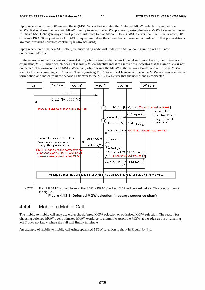
Upon reception of the SDP answer, the (G)MSC Server that initiated the "deferred MGW" selection shall seize a MGW. It should use the received MGW identity to select the MGW, preferably using the same MGW to save resources, if it has a Mc H.248 gateway control protocol interface to that MGW. The (G)MSC Server shall then send a new SDP offer in a PRACK request or an UPDATE request including the connection address and an indication that preconditions are met (provided upstream continuity is also achieved).
Upon reception of the new SDP offer, the succeeding node will update the MGW configuration with the new connection address.
In the example sequence chart in Figure 4.4.3.1, which assumes the network model in Figure 4.4.2.1, the offerer is an originating MSC Server, which does not signal a MGW identity and at the same time indicates that the user plane is not connected. The answerer is an MSC-IW-Server, which seizes the MGW at the network border and returns the MGW identity to the originating MSC Server. The originating MSC Server is able to select the same MGW and seizes a bearer termination and indicates in the second SDP offer to the MSC-IW Server that the user plane is connected.
NOTE: If an UPDATE is used to send the SDP, a PRACK without SDP will be sent before. This is not shown in the figure.
Figure 4.4.3.1: Deferred MGW selection (message sequence chart)
4.4.4 Mobile to Mobile Call
The mobile to mobile call may use either the deferred MGW selection or optimised MGW selection. The reason for choosing deferred MGW over optimised MGW would be to attempt to select the MGW at the edge as the originating MSC does not know where the call will finally terminate.
An example of mobile to mobile call using optimised MGW selection is show in Figure 4.4.4.1.

ETSI
ETSI TS 123 231 V14.0.0 (2017-04)163GPP TS 23.231 version 14.0.0 Release 14
MSC Server B
MSC Server B
UTRAN (IP)
UTRAN
SIP-I Offer (IAM, full SDP, MGW Id])
GCP /IP GCP/IP
RANAP /IP
T1 T2 T3 T4 T1 T2 T1 T2 T3 T4 T3 T4
Iu UP
TRA
IP
SIP-I Answer (Connection address/port )
Nb UP/ IP (virtual)
RANAP /IP
UTRAN (IP)
UTRAN
Iu UP
Figure 4.4.4.1: Optimised MGW Selection for mobile to mobile calls
4.4.5 MGW bypass
In call scenarios without the need for the GMSC or Intermediate Node server to manipulate the bearer, the GMSC or Intermediate Node may perform call control signalling without any associated MGW by not inserting a MGW in the bearer path during the call establishment. In that case, the bearer related information of SDP offers/answers shall be passed transparently through the (G)MSC Server.
Call scenarios where the GMSC or Intermediate Node needs to manipulate the bearer, e.g. scenarios with insertion of tones or announcements, lawful interception, CAMEL services do not allow this optimisation.
MGW removal and MGW re-insertion scenarios once the call is answered are not supported.
Figure 4.4.5.1 shows an example network model for a mobile terminating call with MGW bypass. The "squared" line represents the call control signalling. The "dotted" line represents the bearer control signalling (not applicable in A/Gb mode for the A-interface) and the bearer.
PSTN/ISDN PLMN (TDM)
PLMN / external network
MSC Server
GMSC Server
UTRAN (IP)
BSC/RNC
GCP /IP
-
T1 T2 T1 T2 T1 T2
MGW
MGW bypass
SIP-I /Nc
Figure 4.4.5.1: Terminating call establishment with MGW bypass (network model)
ETSI
ETSI TS 123 231 V14.0.0 (2017-04)173GPP TS 23.231 version 14.0.0 Release 14
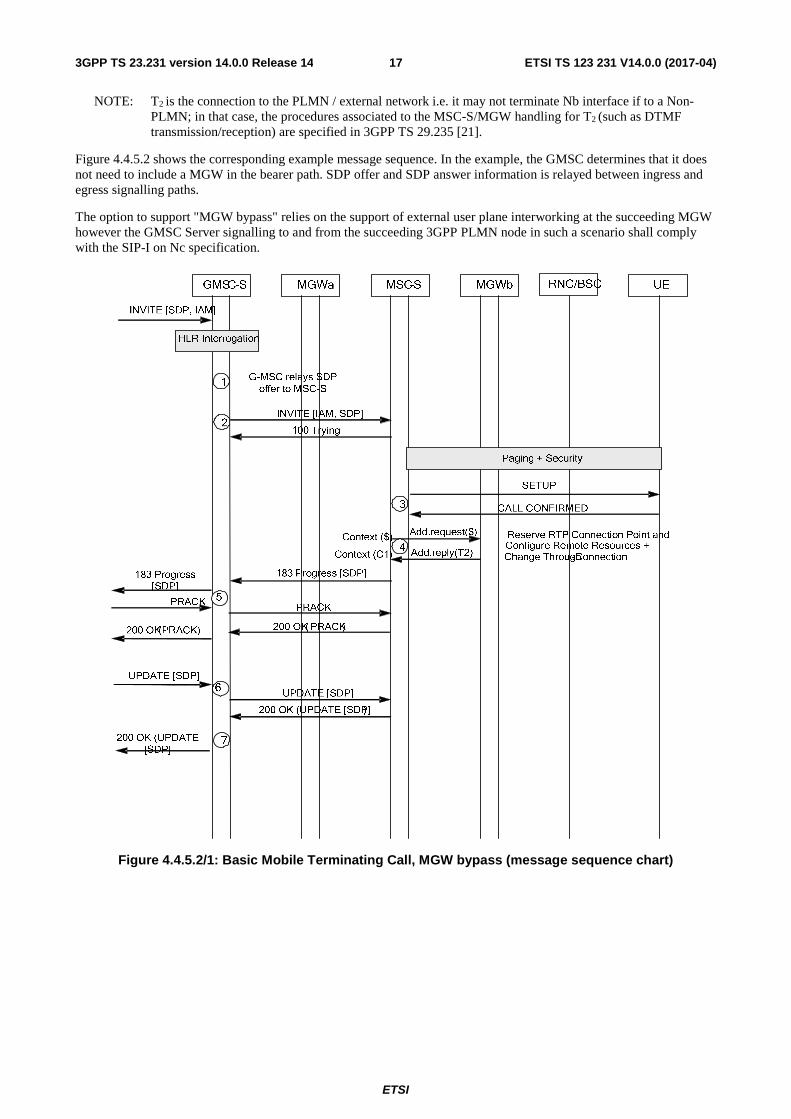
NOTE: T2 is the connection to the PLMN / external network i.e. it may not terminate Nb interface if to a Non-PLMN; in that case, the procedures associated to the MSC-S/MGW handling for T2 (such as DTMF transmission/reception) are specified in 3GPP TS 29.235 [21].
Figure 4.4.5.2 shows the corresponding example message sequence. In the example, the GMSC determines that it does not need to include a MGW in the bearer path. SDP offer and SDP answer information is relayed between ingress and egress signalling paths.
The option to support "MGW bypass" relies on the support of external user plane interworking at the succeeding MGW however the GMSC Server signalling to and from the succeeding 3GPP PLMN node in such a scenario shall comply with the SIP-I on Nc specification.
Figure 4.4.5.2/1: Basic Mobile Terminating Call, MGW bypass (message sequence chart)

ETSI
ETSI TS 123 231 V14.0.0 (2017-04)183GPP TS 23.231 version 14.0.0 Release 14
MGWaGMSC MSC MGWb RNC/BSC UE
Bearer Establishment and Iu UP Initialization
Add.reply(T1)
Add.request($)Context (C1)
Context (C1)9 Prepare Bearer +
Change Through-Connection
180 Ringing [ACM]
PRACK
200 OK (PRACK)
RAB_ASSIGNMENT_COMPL
RAB_ASSIGNMENT_REQ
UMTS:
Add.reply(T1)
Add.request(T1)Context (C1)
Context (C1)Reserve Circuit +Change Through-Connection
ASSIGNMENT_COMPL
ASSIGNMENT_REQUEST
GSM:
ALERTING
180 Ringing [ACM]
200 OK( PRACK)
PRACK
Mod.reply(T2)
Mod.request(T2)Context (C1)
Context (C1)
Send Tone (Start providing a ringing tone for a speech call)
CONNECT
Mod.reply(T1)
Mod.request(T1)Context (C1)
Context (C1)
Change Through- Connection +Activate Inter- Working Function (when applicable) +Activate Voice Processing Function
(when applicable)
Mod.reply(T2)
Mod.request(T2)Context (C1)
Context (C1)
Activate Inter- Working Function (when applicable) +Activate Voice Processing Function (when applicable)
200 OK – INVITE [ANM]
ACK
200 OK( INVITE[ANM])
ACK
12
11
15
13
14
10
Figure 4.4.5.2/2: Basic Mobile Terminating Call, MGW bypass (message sequence chart continue)
5 General Circuit Switched Core Network Domain Architecture
The General CS core network domain architecture is specified in 3GPP TS 23.205 [7].

ETSI
ETSI TS 123 231 V14.0.0 (2017-04)193GPP TS 23.231 version 14.0.0 Release 14
6 Call Establishment NOTE: All message sequence charts in this clause are examples. All valid call establishment message sequences
can be derived from the example message sequences and associated message pre-conditions.
6.1 Basic Mobile Originating Call
6.1.1 Basic Mobile Originating Call Establishment with immediate MGW selection
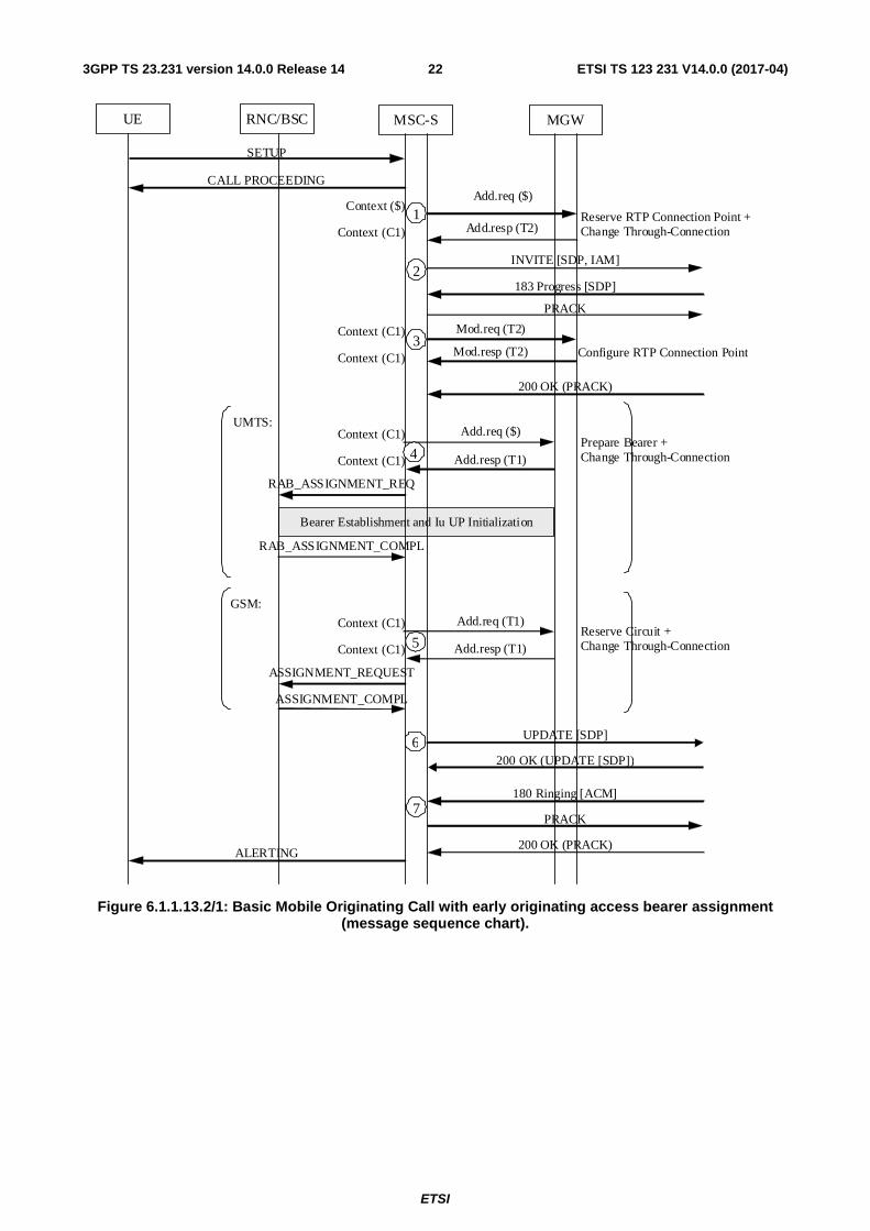
6.1.1.1 General
The mobile originating call shall be established in accordance with 3GPP TS 23.108 [11]. The following clauses describe the additional requirements for the SIP-I based CS core network. The Offer/Answer Procedures of the Session Description Protocol (SDP) for media negotiation shall be applied as specified in 3GPP TS 29.231 [4].
If multiple speech codecs are offered, Out of Band Transcoder Control (OoBTC) procedures shall be applied by the Originating MSC server in accordance with 3GPP TS 23.153 [3]. Otherwise for speech calls only the default PCM speech codec shall be signalled in an SDP offer; auxiliary payload types such as the Telephony Event RTP payload type may be included in addition. The handling of such auxiliary payload types is described in specific clauses (e.g. DTMF is described in Clause 14.4).
For data calls the procedures in 3GPP TS 29.007 [6] are applicable.
6.1.1.2 MGW selection
The MSC server shall select an MGW for the bearer connection before it performs the access bearer assignment or the network side connection point reservation. This shall happen before sending the INVITE message.
6.1.1.3 Initial INVITE message
The MSC server shall send the initial INVITE message before or after the access bearer assignment is completed. The MSC server shall provide the supported SDP (e.g. core network side user plane IP transport address and port, codec(s), RTP telephony event) to the succeeding node in the initial INVITE message. The initial INVITE message shall encapsulate the IAM message. If the access bearer assignment has not been completed, the MSC server shall indicate that the local precondition has not been met.
6.1.1.4 Network side bearer establishment
The MSC server shall select the codec for this connection and request the MGW to select and provide the IP transport address and port for the network side bearer connection before sending the INVITE message. If OoBTC is supported, the selected codec may be the preferred codec for this connection. The MSC server shall use the Reserve RTP Connection Point procedure (bullet 1 in figure 6.1.1.13.2). Within this procedure, the MSC server shall indicate the codec and any additional payload types (e.g. RTP Telephony Event) and shall request a local IP address and UDP port from the MGW. The MSC server may indicate that the IP interface type is for Nb over IP with SIP-I based Nc. The local IP address and UDP port are used by the MGW to receive user plane data from the succeeding MGW.
Support and selection of CS Data payload types is described in 3GPP TS 29.007 [6].
The MGW shall reply to the MSC server with the selected local IP address and UDP port.
The MSC server shall send this information in the INVITE (bullet 2 in figure 6.1.1.13.2) to the succeeding node.
After the succeeding node has provided the SDP answer, the MSC server shall use the Configure RTP Connection Point procedure to request the MGW to configure the remote address, codec and any additional negotiated payload types (e.g. RTP Telephony Event) (bullet 3 in figure 6.1.1.13.2) of the bearer termination. If OoBTC is supported, the Configure RTP Connection Point procedure may amend the selected codec for this connection if different from the codec sent in the previous Reserve RTP Connection Point procedure (bullet 1 in figure 6.1.1.13.2). The Configure RTP Connection Point procedure may indicate that the IP interface type is for Nb over IP with SIP-I based Nc.

ETSI
ETSI TS 123 231 V14.0.0 (2017-04)203GPP TS 23.231 version 14.0.0 Release 14
6.1.1.5 Access bearer assignment
The access bearer assignment is defined in the clause 6.1.1.4 of 3GPP TS 23.205 [7].
6.1.1.6 Framing protocol initialisation
There is no specific framing protocol initialisation in the SIP-I based CS network. The MGW terminates the Iu Framing Protocol towards the Iu interface and will receive an Iu UP Initialisation from an Iu-CS interface connected to the radio interface and shall process it according to the procedures in 3GPP TS 25.415 [22] and 3GPP TS 29.232 [8]. No information from the framing protocol initialisation needs to be interworked towards the Nb interface of a SIP-I based CS core network. Information within subsequent Iu UP payload PDUs and RTP PDUs shall be interworked according to the procedures in TS 29.414 [23].
6.1.1.7 Through-Connection
In combination with the Prepare Bearer or Reserve Circuit procedures, and the Reserve RTP Connection Point or Configure RTP Connection Point procedure, the MSC server should use the Change Through-Connection procedure to request the MGW to configure the bearer terminations so that the bearer is through-connected in the backward direction (bullet 1 or 3 and bullet 4 or 5 in figure 6.1.1.13.2).
For a multimedia call, the MSC may request the MGW to both-way through-connect the bearer using the Change Through-Connection procedure to generate a multimedia CAT (see subclause 14.10.1).
Otherwise when the MSC server receives the answer indication (200 OK(INVITE)), it shall request the MGW to both-way through-connect the bearer using the Change Through-Connection procedure (bullet 8 in figure 6.1.1.13.2), unless the bearer has already been both way through-connected at an earlier stage.
6.1.1.8 Confirmation of bearer establishment
If the initial INVITE message which was sent to the succeeding node indicated that the local precondition has not been met, the MSC server shall send an UPDATE message indicating that the local preconditions are met when the access bearer assignment has been completed (bullet 6 in figure 6.1.1.13.2).
6.1.1.9 Interworking function
The MGW may use an interworking function that is based on the PLMN Bearer Capability, 3GPP TS 24.008 [14], of the bearer termination. The activation of the possible interworking function in both bearer terminations will be requested by the MSC server at reception of the SIP 200 OK (INVITE) response using the Activate Interworking Function procedure (bullet 8 in figure 6.1.1.13.2).
6.1.1.10 Codec handling
The MGW may include a speech transcoder based upon the speech coding information provided to each bearer termination.
6.1.1.11 Voice Processing function
A voice processing function (i.e. echo cancellation) located on the MGW may be used to achieve desired acoustic quality on the bearer terminations. The MSC server shall request the activation of voice processing functions in the bearer terminations. For non-speech calls, the MSC server has the ability to instruct the MGW to disable the voice processing functions (bullet 8 in figure 6.1.1.13.2/2).
6.1.1.12 Failure handling in MSC server
If any procedure between the MSC server and the MGW has not completed successfully or the MSC server receives a Bearer Released procedure from the MGW, the call shall be cleared as described in clause 7.2.4, visited MSC server initiated call clearing or in clause 7.2.5, MGW initiated call clearing. Alternatively, the MSC server may only release the resources in the MGW that caused the failure, possibly select a new MGW for the bearer connection and continue the call establishment using new resources in the selected MGW.

ETSI
ETSI TS 123 231 V14.0.0 (2017-04)213GPP TS 23.231 version 14.0.0 Release 14
6.1.1.13 Example
Figure 6.1.1.13.1 shows the network model for the mobile originating call. The "squared" line represents the call control signalling. The "dotted" line represents the bearer control signalling (not applicable in A/Gb mode for the A-interface) and the bearer. The MSC server seizes one context with two terminations in the MGW. The bearer termination T1 is used for the bearer towards the RNC/BSC and the bearer termination T2 is used for the bearer towards the succeeding MGW.
Figure 6.1.1.13.1: Basic Mobile Originating Call (network model)
MGW
MSC-S
CTX1T1 T2
RNC/BSC
ETSI
ETSI TS 123 231 V14.0.0 (2017-04)223GPP TS 23.231 version 14.0.0 Release 14
RNC/BSC UE MGW MSC-S
SETUP
CALL PROCEEDING
Add.resp (T2)
Add.req ($) Context ($)
Context (C1)
Add.resp (T1)
Add.req ($) Context (C1)
Context (C1)
UMTS:
RAB_ASSIGNMENT_REQ
RAB_ASSIGNMENT_COMPL
Bearer Establishment and Iu UP Initialization
Prepare Bearer + Change Through-Connection
Reserve RTP Connection Point + Change Through-Connection
Add.resp (T1)
Add.req (T1) Context (C1)
Context (C1)
GSM:
ASSIGNMENT_REQUEST
ASSIGNMENT_COMPL
Reserve Circuit + Change Through-Connection
INVITE [SDP, IAM]
183 Progress [SDP]
PRACK
200 OK (PRACK)
180 Ringing [ACM]
PRACK
200 OK (PRACK) ALERTING
1
4
5
Mod.resp (T2)
Mod.req (T2) Context (C1)
Context (C1) Configure RTP Connection Point
2
6 UPDATE [SDP]
200 OK (UPDATE [SDP])
7
3
Figure 6.1.1.13.2/1: Basic Mobile Originating Call with early originating access bearer assignment (message sequence chart).

ETSI
ETSI TS 123 231 V14.0.0 (2017-04)233GPP TS 23.231 version 14.0.0 Release 14
RNC/BSC UE MGW MSC-S
200 OK – INVITE [ANM]
ACK
CONNECT
Mod.resp (T1)
Mod.req (T1) Context (C1)
Context (C1)
Change Through-Connection + Activate Inter-Working Function (when applicable) + Activate Voice Processing Function (when applicable)
Mod.resp (T2)
Mod.req (T2) Context (C1)
Context (C1)
Activate Inter-Working Function (when applicable) + Activate Voice Processing Function (when applicable)
8
Figure 6.1.1.13.2/2: Basic Mobile Originating Call with early originating access bearer assignment (message sequence chart).
6.1.2 Originating Call Establishment For Iu Interface on IP with immediate MGW selection
For IP transport over the IuCS interface the procedures in the present Clause shall apply in addition to the SIP-I based Core Network side procedures described in 6.1.1.
For the access side termination, the exchange of IP addresses as defined in the clause 6.1.3 of 3GPP TS 23.205 [3] shall apply.
If the bearer transport is IP and IuUP mode is Support, the MGW shall use the source IP address and UDP Port of the IuUP Init packet received from the radio access network as the destination address for subsequent downlink packets.
The sequence is shown in Figure 6.1.2.1.

ETSI
ETSI TS 123 231 V14.0.0 (2017-04)243GPP TS 23.231 version 14.0.0 Release 14
RNC/BSC UE MGW MSC-S
SETUP
CALL PROCEEDING
Add.resp (T2)
Add.req ($) Context ($)
Context (C1)
Add.resp (T1)
Add.req ($) Context (C1)
Context (C1)
RAB_ASSIGNMENT_REQ
RAB_ASSIGNMENT_COMPL
Bearer Establishment and Iu UP Initialization
Prepare_IP_Transport + Change Through-Connection
Reserve RTP Connection Point + Change Through-Connection
INVITE [SDP, IAM]
183 Progress [SDP]
PRACK
200 OK - PRACK
1
4
Mod.resp (T2)
Mod.req (T2) Context (C1)
Context (C1) Configure RTP Connection Point
2
6 UPDATE [SDP]
200 OK – UPDATE [SDP]
3
Add.resp (T1)
Add.req (T1) Context (C1)
Context (C1) Modify IP Transport Address
5
For IuUP in Support Mode
For IuUP in Transparent Mode
Figure 6.1.2.1: Originating Call Establishment for Iu on IP
6.1.3 Originating Call Establishment For A Interface user plane over IP with immediate MGW selection
For A interface user plane over IP, the procedures in the present Clause shall apply in addition to the SIP-I based Core Network side procedures described in 6.1.1.
For the access side termination, the exchange of IP addresses as defined in the clause 6.1.5 of 3GPP TS 23.205 [7] shall apply.
The sequence is shown in Figure 6.1.3.1.
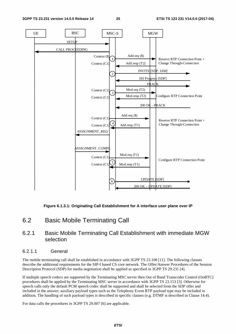
ETSI
ETSI TS 123 231 V14.0.0 (2017-04)253GPP TS 23.231 version 14.0.0 Release 14
BSC UE MGW MSC-S
SETUP
CALL PROCEEDING
Add.resp (T2)
Add.req ($) Context ($)
Context (C1)
Add.resp (T1)
Add.req ($) Context (C1)
Context (C1)
ASSIGNMENT_REQ
ASSIGNMENT_COMPL
Reserve RTP Connection Point + Change Through-Connection
Reserve RTP Connection Point + Change Through-Connection
INVITE [SDP, IAM]
183 Progress [SDP]
PRACK
200 OK - PRACK
1
4
Mod.resp (T2)
Mod.req (T2) Context (C1)
Context (C1) Configure RTP Connection Point
2
6 UPDATE [SDP]
200 OK – UPDATE [SDP]
3
Mod.resp (T1)
Mod.req (T1) Context (C1)
Context (C1) Configure RTP Connection Point
5
Figure 6.1.3.1: Originating Call Establishment for A interface user plane over IP
6.2 Basic Mobile Terminating Call
6.2.1 Basic Mobile Terminating Call Establishment with immediate MGW selection
6.2.1.1 General
The mobile terminating call shall be established in accordance with 3GPP TS 23.108 [11]. The following clauses describe the additional requirements for the SIP-I based CS core network. The Offer/Answer Procedures of the Session Description Protocol (SDP) for media negotiation shall be applied as specified in 3GPP TS 29.231 [4].
If multiple speech codecs are supported by the Terminating MSC server then Out of Band Transcoder Control (OoBTC) procedures shall be applied by the Terminating MSC server in accordance with 3GPP TS 23.153 [3]. Otherwise for speech calls only the default PCM speech codec shall be supported and shall be selected from the SDP offer and included in the answer; auxiliary payload types such as the Telephony Event RTP payload type may be included in addition. The handling of such payload types is described in specific clauses (e.g. DTMF is described in Clause 14.4).
For data calls the procedures in 3GPP TS 29.007 [6] are applicable.
ETSI
ETSI TS 123 231 V14.0.0 (2017-04)263GPP TS 23.231 version 14.0.0 Release 14
6.2.1.2 GMSC server
6.2.1.2.1 MGW selection
The GMSC server shall select an MGW for the bearer connection before it performs the incoming side bearer establishment or the outgoing side bearer establishment. This shall happen before sending the initial INVITE message.
6.2.1.2.2 Initial INVITE message
The GMSC server shall indicate in the initial INVITE message that the precondition has not been met if either of the following conditions is satisfied before sending the initial INVITE message:
1. The incoming INVITE(IAM) indicated that remote preconditions had not been met, and no new SDP has been received indicating that preconditions have been met.
2. The incoming side RTP connection point has not been successfully reserved and configured in the MGW.
The GMSC shall provide the supported SDP (e.g. core network side user plane IP transport address and port, codec(s), RTP telephony event) to the succeeding node in the initial INVITE message.
6.2.1.2.3 Outgoing side bearer termination configuration
The GMSC server shall select the codec for the outgoing side bearer connection before it performs the Reserve RTP Connection Point procedure. If OoBTC is supported, the selected codec may be the preferred codec for this connection.
After the succeeding node has provided a user plane IP transport address and port the GMSC server shall use the Configure RTP Connection Point procedure to request the MGW to configure the remote address and any additional negotiated payload types (e.g. RTP Telephony Event) of the bearer termination. If OoBTC is supported, the Configure RTP Connection Point procedure may amend the selected codec for this connection if different from the codec sent in the previous Reserve RTP Connection Point procedure.
Both the Reserve RTP Connection Point procedure and the Configure RTP Connection Point procedure may indicate that the IP interface type is for Nb over IP with SIP-I based Nc.
6.2.1.2.4 Incoming side bearer termination configuration
The GMSC server shall request the MGW to prepare for the incoming side bearer establishment using the Reserve and Configure RTP Connection Point procedure. The GMSC server shall select the codec for the incoming side bearer connection before it performs the Reserve and Configure RTP Connection Point procedure. Within this procedure, the GMSC server shall request the MGW to provide a local user plane IP address and UDP port and may indicate that the IP interface type is for Nb over IP with SIP-I based Nc. The GMSC server shall also provide the MGW with the selected codec, the remote user plane IP address and port information that was received from the preceding node in the INVITE message and any additional payload types (e.g. RTP Telephony Event). The GMSC server shall include in the SDP answer to the preceding node: the user plane IP address and UDP port received from the MGW, the selected codec and any additional accepted payload types.
NOTE: The incoming side bearer establishment may take place either before or after HLR interrogation.
6.2.1.2.5 Through-Connection
In combination with the Reserve RTP Connection Point or Configure RTP Connection Point procedures and with the Reserve and Configure RTP Connection Point procedure, the GMSC server should use the Change Through-Connection procedure to request the MGW to both-way through-connect the bearer termination.
6.2.1.2.6 Indication of bearer establishment
The core network side bearer is established if the following conditions are satisfied:
1. Either:
a. The incoming INVITE(IAM) indicated that remote preconditions had not been met, and new SDP has been received indicating that preconditions have been met, or
ETSI
ETSI TS 123 231 V14.0.0 (2017-04)273GPP TS 23.231 version 14.0.0 Release 14
b. The incoming INVITE(IAM) did not include any preconditions information or indicated that remote preconditions had been met;
and
2. Either:
a. The incoming side RTP connection point has been successfully reserved and configured in the MGW, or
b. MGW selection is not required for this call.
If the initial INVITE message which was sent to the succeeding node indicated that the precondition has not been met, the GMSC server shall send an UPDATE message indicating that the preconditions are met when the core network side bearer is established (bullet 8 in figure 6.2.1.3.14.2).
6.2.1.2.7 Voice Processing function
A voice processing function (i.e. echo cancellation) located on the MGW may be used to achieve desired acoustic quality on the bearer terminations. The GMSC server shall request the activation of the voice processing functions in the bearer terminations. For non-speech calls, the GMSC server has the ability to instruct the MGW to disable the voice processing functions (bullet 14 in figure 6.2.1.3.14.2/2).
6.2.1.2.8 Failure handling in GMSC server
If any procedure between the GMSC server and the MGW has not completed successfully or the GMSC server receives a Bearer Released procedure from the MGW, the call shall be cleared as described in clause 7.3.2, GMSC server initiated call clearing or in clause 7.3.3, MGW initiated call clearing. Alternatively, the GMSC server may only release the resources in the MGW that caused the failure, possibly select a new MGW for the bearer connection and continue the call establishment using new resources in the selected MGW.
6.2.1.3 MSC server
6.2.1.3.1 Paging
The Paging is defined in the clause 6.1.1.4 of 3GPP TS 23.205 [7].
6.2.1.3.2 Call setup
The MSC Server shall send a SETUP message towards the UE.
According to TS 23.108 [11], the MSC server can either apply the early access bearer assignment procedure, i.e. the MSC does not include the signal IE in the SETUP to request that the user is alerted only after the setup of the access bearer as specified in3GPP TS 24.008 [14]), or the MSC server can apply the late access bearer assignment procedure, i.e. the MSC includes the signal IE in the SETUP to request that the user is immediately alerted.
For basic call setup the MSC server should apply the early access bearer assignment procedure to ensure that the terminating UE is not alerted until the end to end bearer is established.
NOTE: The late access bearer assignment procedure can result in clipping, alerting of the user if the core network side bearer or radio bearer establishment fails, and related charging of failed calls.
6.2.1.3.3 MGW selection
The MSC server shall select an MGW for the bearer connection before it performs the network side bearer establishment or the access bearer assignment. This happens at latest after the UE has sent the Call Confirmed message.
Editor's Note: For GSM, if performing Service based handover (see 3GPP TS 48.008 [12]), the MSC Server may omit MGW selection at this time. This requires further study.

ETSI
ETSI TS 123 231 V14.0.0 (2017-04)283GPP TS 23.231 version 14.0.0 Release 14
6.2.1.3.4 Network side bearer termination configuration
The MSC server requests the MGW to prepare for the network side bearer establishment using the Reserve and Configure RTP Connection Point procedure (bullet 4 in figure 6.2.1.3.14.2/1). The MSC server shall select the codec for the network side bearer connection before it performs the Reserve and Configure RTP Connection Point procedure. Within this procedure, the MSC server shall request the MGW to provide a local user plane IP address and UDP port and may indicate that the IP interface type is for Nb over IP with SIP-I based Nc. The MSC server shall also provide the MGW with the selected codec and with the remote user plane IP address and port information that was received from the preceding node in the SDP offer. The MSC server shall include in the SDP answer (e.g. 183 SESSION PROGRESS) to the preceding node: the user plane IP address and UDP port received from the MGW, the selected codec and any additional accepted payload types.
6.2.1.3.5 Access bearer assignment
If the early access bearer assignment procedure is used (see 3GPP TS 23.108 [11]), the access bearer assignment shall be started only when the core network bearer is established, as described by the following conditions.
1. Either:
a. The incoming INVITE(IAM) indicated that remote preconditions had not been met, and new SDP has been received indicating that preconditions have been met, or
b. The incoming INVITE(IAM) did not include any preconditions information or indicated that remote preconditions had been met;
and
2. The incoming side RTP connection point has been successfully reserved and configured in the MGW.
The access bearer assignment is defined in the clause 6.2.1.2.5 of 3GPP TS 23.205 [7].
6.2.1.3.6 Framing protocol initialisation
There is no specific framing protocol initialisation requirement in SIP-I based CS network. The MGW terminates the Iu Framing Protocol towards the Iu interface and will receive an IuUP Initialisation from an Iu-CS interface towards the radio interface and shall process it according to the procedures in 3GPP TS 25.415 [22] and 3GPP TS 29.232 [8]. No information from the framing protocol initialisation needs to be interworked towards the Nb interface of a SIP-I based CS core network. Information within subsequent Iu UP payload PDUs and RTP PDUs shall be interworked according to the procedures in TS 29.414 [23].
6.2.1.3.7 Called party alerting
For a speech call, when the MSC server receives an Alerting message, it shall request the MGW to provide a ringing tone to the calling party using the Send Tone procedure (bullet 11 in figure 6.2.1.3.14.2/1).
NOTE: Other kind of tones may be provided to the calling party at an earlier stage of the call establishment.
6.2.1.3.8 Called party answer
For a speech call, when the MSC server receives a Connect message, it shall request the MGW to stop providing the ringing tone to the calling party using the Stop Tone procedure (bullet 13 in figure 6.2.1.3.14.2/2).
6.2.1.3.9 Through-Connection
In combination with the Reserve and Configure RTP Connection Point procedure and with the Prepare Bearer procedure or Reserve Circuit procedure, the MSC server should use the Change Through-Connection procedure to request the MGW to through-connect the bearer terminations so that the bearer will be not through connected (bullet 4, and bullet 9 or 10 in figure 6.2.1.3.14.2).
When the MSC server receives the Connect message, it shall request the MGW to both-way through-connect the bearer using the Change Through-Connection procedure (bullet 13 in figure 6.2.1.3.14.2/2).

ETSI
ETSI TS 123 231 V14.0.0 (2017-04)293GPP TS 23.231 version 14.0.0 Release 14
6.2.1.3.10 Interworking function
The MGW may use an interworking function that is based on the PLMN Bearer Capability, 3GPP TS 24.008 [14], of the bearer termination. The activation of the possible interworking function in both bearer terminations will be requested by the MSC server at reception of the Connect message using the Activate Interworking Function procedure (bullet 13 in figure 6.2.1.3.14.2).
6.2.1.3.11 Codec handling
The MGW may include a speech transcoder based upon the speech coding information provided to each bearer termination.
6.2.1.3.12 Voice Processing function
A voice processing function (i.e. echo cancellation) located on the MGW may be used to achieve desired acoustic quality on the bearer terminations. The MSC server shall request the activation of the voice processing functions in the bearer terminations. For non-speech calls, the MSC server has the ability to instruct the MGW to disable the voice processing functions (bullet 13 in figure 6.2.1.3.14.2/2).
6.2.1.3.13 Failure handling in MSC server
If any procedure between the MSC server and the MGW has not completed successfully or the MSC server receives a Bearer Released procedure from the MGW, the call shall be cleared as described in clause 7.2.4, visited MSC server initiated call clearing or in clause 7.2.5, MGW initiated call clearing. Alternatively, the MSC server may only release the resources in the MGW that caused the failure, possibly select a new MGW for the bearer connection and continue the call establishment using new resources in the selected MGW.
6.2.1.3.14 Example - the GMSC selects a MGW
Figure 6.2.1.3.14.1 shows the network model for the basic mobile terminating call. The "squared" line represents the call control signalling. The "dotted" line represents the bearer control signalling (not applicable in A/Gb mode for the A-interface) and the bearer. The MSC server seizes one context with two bearer terminations in MGWb. The bearer termination T1 is used for the bearer towards the RNC/BSC and the bearer termination T2 is used for the bearer towards the GMSC server selected MGWa. The GMSC server seizes one context with two bearer terminations in MGWa. The bearer termination T3 is used for the bearer towards the MSC server selected MGWb and the bearer termination T4 is used for the bearer towards the preceding MGW.
Figure 6.2.1.3.14.1: Basic Mobile Terminating Call Forward Bearer Establishment (network model)
Figure 6.2.1.3.14.2 shows the message sequence example for the basic mobile terminating call. In the example the GMSC server requests from MGWa the seizure of the outgoing side bearer termination before forwarding the INVITE to the MSC server. After the outgoing side bearer termination is seized the GMSC server sends the INVITE with supported SDP to the MSC server. The MSC server requests from MGWb the seizure of the network side bearer termination when Call Confirmed message is received from the UE. The MSC server sends the SDP answer (183 SESSION PROGRESS) to the GMSC. On receipt of the SDP answer, the GMSC requests from MGWa the through connection of the outgoing side bearer termination and the seizure of the incoming side bearer termination. The GMSC
MGWbMGWa
GMSC-S MSC-S
RNC/BSCCTX2T4 T3
CTX1T2 T1

ETSI
ETSI TS 123 231 V14.0.0 (2017-04)303GPP TS 23.231 version 14.0.0 Release 14
server sends the SDP answer (183 SESSION PROGRESS) to the external network. On receipt of the second SDP offer (UPDATE) from the external network, the GMSC server forwards this to the MSC server. The MSC server requests seizure of the access side bearer termination. For a speech call the MSC server requests MGWb to provide a ringing tone to the calling party at alerting. At answer the MSC server requests MGWb to both-way through-connect the bearer. For a speech call the MSC server requests MGWb to stop the ringing tone to the calling party at answer. When the MSC server receives an answer indication, for circuit switched data call it may request the activation of the interworking function in both bearer terminations. The (G)MSC server may request the activation of the voice processing functions for the bearer terminations.
MGWa GMSC-S
INVITE [IAM, SDP]
100 Trying
Add.reply(T3)
Add.request($) Context ($)
Context (C2) 1
MSC-S MGWb RNC/BSC UE
INVITE [SDP, IAM]
HLR Interrogation
Paging + Security
SETUP
CALL CONFIRMED 3
2
Add.reply(T2)
Add.request($) Context ($)
Context (C1) 4
Reserve and Configure RTP Connection Point + Change Through-Connection
183 Progress [SDP]
PRACK
183 Progress [SDP]
PRACK
200 OK (PRACK)
Mod.reply(T3)
Mod.request(T3) Context (C2)
Context (C2) 5 Configure RTP Connection Point +
Change Through-Connection
Reserve RTP Connection Point + Change Through-Connection
200 OK (PRACK)
UPDATE [SDP]
200 OK (UPDATE) [SDP]
Add.reply(T4)
Add.request($) Context (C2)
Context (C2) 6
Reserve and Configure RTP Connection Point +Change Through-Connection
UPDATE [SDP]
200 OK (UPDATE [SDP]) 8
7
Figure 6.2.1.3.14.2/1: Basic Mobile Terminating Call, GMSC selects a MGW (message sequence chart)

ETSI
ETSI TS 123 231 V14.0.0 (2017-04)313GPP TS 23.231 version 14.0.0 Release 14
MGWa GMSC MSC MGWb RNC/BSC UE
Bearer Establishment and Iu UP Initialization
Add.reply(T1)
Add.request($) Context (C1)
Context (C1) 9 Prepare Bearer +
Change Through-Connection
180 Ringing [ACM]
PRACK
200 OK (PRACK)
RAB_ASSIGNMENT_COMPL
RAB_ASSIGNMENT_REQ
UMTS:
Add.reply(T1)
Add.request(T1) Context (C1)
Context (C1) Reserve Circuit + Change Through-Connection
ASSIGNMENT_COMPL
ASSIGNMENT_REQUEST
GSM:
ALERTING
180 Ringing [ACM]
200 OK (PRACK)
PRACK
Mod.reply(T2)
Mod.request(T2) Context (C1)
Context (C1)
Send Tone (Start providing a ringing tone for a speech call)
CONNECT
Mod.reply(T1)
Mod.request(T1) Context (C1)
Context (C1)
Change Through-Connection + Activate Inter-Working Function (when applicable) + Activate Voice Processing Function (when applicable)
Mod.reply(T2)
Mod.request(T2) Context (C1)
Context (C1)
Activate Inter-Working Function (when applicable) + Activate Voice Processing Function (when applicable)
200 OK – INVITE [ANM]
ACK
Mod.reply(T3)
Mod.request(T3) Context (C2)
Context (C2)
Activate Voice Processing Function (when applicable)
Mod.reply(T4)
Mod.request(T4) Context (C2)
Context (C2) Activate Voice Processing Function (when applicable)
200 OK (INVITE [ANM])
ACK
12
11
15
13
14
10
Figure 6.2.1.3.14.2/2: Basic Mobile Terminating Call, GMSC selects a MGW (message sequence chart continue)
ETSI
ETSI TS 123 231 V14.0.0 (2017-04)323GPP TS 23.231 version 14.0.0 Release 14
6.2.2 Terminating Call Establishment For Iu Interface on IP with immediate MGW selection
For IP transport over the IuCS the procedures in the present Clause shall apply in addition to the SIP-I based Core Network side procedures described in Clause 6.2.1.
For the access side termination, the exchange of IP addresses as defined in the Clause 6.2.3 of 3GPP TS 23.205 [7] shall apply.
If the bearer transport is IP and IuUP mode is Support, the MGW shall use the source IP address and UDP Port of the IuUP Init packet received from the radio access network as the destination address for subsequent downlink packets.
The sequence is shown in Figure 6.2.2.1.
MGWa GMSC MSC MGWb RNC/BSC UE
Bearer Establishment and Iu UP Initialization
Add.reply(T1)
Add.request($) Context (C1)
Context (C1) 8 Prepare_IP_Transport +
Change Through-Connection
RAB_ASSIGNMENT_COMPL
RAB_ASSIGNMENT_REQ
UMTS:
For preceding signalling sequences see Figures 6.2.1.3.14.2
For succeeding signalling sequences see Figures 6.2.1.3.14.2
Mod.reply(T1)
Mod.request(T1) Context (C1)
Context (C1) Modify IP Transport Address
For IuUP in Transparent Mode
For IuUP in Support Mode
Figure 6.2.2.1: Terminating Call Establishment for Iu on IP
6.2.3 Terminating Call Establishment For A Interface user plane over IP with immediate MGW selection
For A interface user plane over IP, the procedures in the present Clause shall apply in addition to the SIP-I based Core Network side procedures described in Clause 6.2.1.
For the access side termination, the exchange of IP addresses as defined in the Clause 6.2.4 of 3GPP TS 23.205 [7] shall apply.
The sequence is shown in Figure 6.2.3.1.
ETSI
ETSI TS 123 231 V14.0.0 (2017-04)333GPP TS 23.231 version 14.0.0 Release 14
MGWa GMSC MSC MGWb BSC UE
Add.reply(T1)
Add.request($) Context (C1)
Context (C1) 8 Reserve RTP Connection Point +
Change Through-Connection
ASSIGNMENT_COMPL
ASSIGNMENT_REQ
GSM:
For preceding signalling sequences see Figures 6.2.1.3.14.2
For succeeding signalling sequences see Figures 6.2.1.3.14.2
Mod.reply(T1)
Mod.request(T1) Context (C1)
Context (C1) Configure RTP Connection Point
Figure 6.2.3.1: Terminating Call Establishment for A interface user plane IP
7 Call Clearing
7.1 General The terms "incoming" and "outgoing" in the following text refers to the direction of propagation of the release indication, not to the direction of original call establishment.
During call establishment, the call may be released by sending a BYE or CANCEL request in the direction of the original call establishment, or by a failure response in the opposite direction of the original call establishment. For an established call, the call may be released by BYE request in the direction of the original call establishment or in the opposite direction of the original call establishment.
The term "release indication" in the following text refers to any message which is to release the call, i.e. it may be the BYE or CANCEL request, or the failure response to the initial INVITE request.
In accordance with ITU-T Q.1912.5 [9] Profile C, the generation of:
- a BYE request and a 4xx, 5xx, 6xx final response to initial INVITE should encapsulate an ISUP REL message.
NOTE: there can be cases where it may not be possible to encapsulate an ISUP REL due to some specific error scenarios. Additionally it is possible that an IWU forwards a BYE or a 4xx, 5xx, 6xx final response without a REL.
- a 200 OK final response to a BYE request shall encapsulate an ISUP RLC message if a BYE is received with an encapsulated REL.
The user initiated call clearing shall be performed in accordance with 3GPP TS 23.108 [18].
NOTE: All message sequence charts in this clause are examples. All valid call clearing message sequences can be derived from the example message sequences and associated message pre-conditions.

ETSI
ETSI TS 123 231 V14.0.0 (2017-04)343GPP TS 23.231 version 14.0.0 Release 14
7.2 Visited MSC Server Procedures
7.2.1 Call Clearing when Visited MSC Server has Forwarded/Deflected Call
If the MSC server has forwarded/deflected the call to another terminating MSC server, call clearing is performed as described for the GMSC Server in clause 7.3.
7.2.2 Call Clearing received from core network
7.2.2.1 Procedures towards access side
The MSC server initiates call clearing towards the UE and requests release of the associated radio resources as described in 3GPP TS 23.108[18]. Once the call clearing and the release of the associated radio resources have been completed, the MSC server releases any MGW allocated resources for the access side. If any resources were seized in the MGW, the MSC server uses the Release Termination procedure to requests the MGW to remove the access side bearer termination.
7.2.2.2 Procedures towards network side
7.2.2.2.1 Call Clearing during establishment
7.2.2.2.1.1 Originating MSC-S
If the release indication from the succeeding node is a failure response for the initial INVITE request, the MSC server shall send an ACK for the failure response to the succeeding node.
The MSC server shall then perform the normal bearer release according to 7.2.6.
NOTE: For early dialogue from O-MSC perspective, a BYE can only be received if it overtakes a 2xx response due to out-of-sequence packet delivery which should not be encountered with SCTP transport for SIP, as used on Nc
7.2.2.2.1.2 Terminating MSC-S
If a CANCEL request to initial INVITE is received from the preceding node, the MSC server shall send a 200 OK response for the CANCEL request and the MSC server shall immediately send a 487 Request Terminated response for the initial INVITE request to the preceding node.
NOTE: No final response for the initial INVITE request has previously been sent.
If a BYE request is received from the preceding node, the MSC server shall send a 200 OK response for the BYE request, and immediately send a 487 Request Terminated response for the initial INVITE request to the preceding node.
NOTE: A 487 final response is sent because of a reception of CANCEL/BYE request and does not contain encapsulated REL message.
The MSC sever shall then perform the normal bearer release according to 7.2.6.
7.2.2.2.2 Call Clearing after call established
7.2.2.2.2.1 Originating MSC-S
An MSC server that receives a BYE request from the succeeding node shall send a 200 OK response for the BYE request to the succeeding node. The MSC shall then perform the normal bearer release according to 7.2.6.

ETSI
ETSI TS 123 231 V14.0.0 (2017-04)353GPP TS 23.231 version 14.0.0 Release 14
7.2.2.2.2.2 Terminating MSC-S
If an MSC server receives a CANCEL request from the preceding node it shall send a 200 OK(CANCEL) final response for the CANCEL request but shall not take further action.
If a BYE request is received from the preceding node, the MSC server shall send a 200 OK response for the BYE request to the preceding node. The MSC server shall then perform the normal bearer release according to 7.2.6.
7.2.2.3 Example Call Flow
Figure 7.2.2.3.1 shows the network model for a network initiated clearing of an established mobile call. The "squared" line represents the call control signalling. The "dotted" line represents the bearer control signalling (not applicable in A/Gb mode for the A-interface) and the bearer. The MSC server seizes one context with two bearer terminations in the MGW. Bearer termination T1 is used for the bearer towards RNC/BSC and bearer termination T2 is used for the bearer towards succeeding MGW.
Figure 7.2.2.3.1: Network Initiated Call Clearing (Network model)
Figure 7.2.2.3.2 shows the message sequence example for the network initiated clearing of an established mobile call. In the example when the call clearing indication is received from the preceding/succeeding node, the MSC server indicates to the preceding/succeeding node that call clearing has been completed and releases the network side bearer termination. The MSC server initiates call clearing towards the UE and requests release of the radio resource. After the response of the radio resource release is received then the MSC server requests release of the access side bearer termination.
MGW
MSC-S
CTX1T1 T2
RNC/BSC

ETSI
ETSI TS 123 231 V14.0.0 (2017-04)363GPP TS 23.231 version 14.0.0 Release 14
GSM:
UMTS:
Release Termination
CLEAR COMPLETE
CLEAR COMMAND
Context(C1) SUB.reply (T1)
Context (C1) SUB.request (T1)
3
Release Termination
Release Termination
IU RELEASE COMPLETE
REL
RLC
DISCONNECT
IU RELEASE CMD
Context(C1) SUB.reply (T1)
Context (C1) SUB.request (T1)
BYE
SUB.request(T2) (T2)
Context (C1) SUB.reply (T2)
200 OK (BYE)
UE RNC/BSC MSC-S MGW
1
2
Bearer Release
Figure 7.2.2.3.2: Network Initiated Call Clearing (message sequence chart)
7.2.3 Call Clearing received from UE
7.2.3.1 Procedures towards access side
Call clearing from the UE shall be performed in accordance with clause 7.2.2.1 in 3GPP TS 23.205 [7].
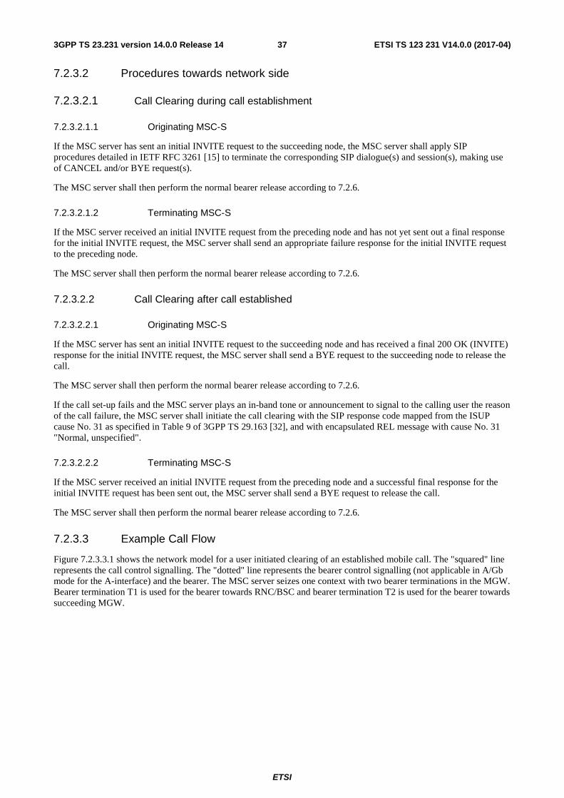
ETSI
ETSI TS 123 231 V14.0.0 (2017-04)373GPP TS 23.231 version 14.0.0 Release 14
7.2.3.2 Procedures towards network side
7.2.3.2.1 Call Clearing during call establishment
7.2.3.2.1.1 Originating MSC-S
If the MSC server has sent an initial INVITE request to the succeeding node, the MSC server shall apply SIP procedures detailed in IETF RFC 3261 [15] to terminate the corresponding SIP dialogue(s) and session(s), making use of CANCEL and/or BYE request(s).
The MSC server shall then perform the normal bearer release according to 7.2.6.
7.2.3.2.1.2 Terminating MSC-S
If the MSC server received an initial INVITE request from the preceding node and has not yet sent out a final response for the initial INVITE request, the MSC server shall send an appropriate failure response for the initial INVITE request to the preceding node.
The MSC server shall then perform the normal bearer release according to 7.2.6.
7.2.3.2.2 Call Clearing after call established
7.2.3.2.2.1 Originating MSC-S
If the MSC server has sent an initial INVITE request to the succeeding node and has received a final 200 OK (INVITE) response for the initial INVITE request, the MSC server shall send a BYE request to the succeeding node to release the call.
The MSC server shall then perform the normal bearer release according to 7.2.6.
If the call set-up fails and the MSC server plays an in-band tone or announcement to signal to the calling user the reason of the call failure, the MSC server shall initiate the call clearing with the SIP response code mapped from the ISUP cause No. 31 as specified in Table 9 of 3GPP TS 29.163 [32], and with encapsulated REL message with cause No. 31 "Normal, unspecified".
7.2.3.2.2.2 Terminating MSC-S
If the MSC server received an initial INVITE request from the preceding node and a successful final response for the initial INVITE request has been sent out, the MSC server shall send a BYE request to release the call.
The MSC server shall then perform the normal bearer release according to 7.2.6.
7.2.3.3 Example Call Flow
Figure 7.2.3.3.1 shows the network model for a user initiated clearing of an established mobile call. The "squared" line represents the call control signalling. The "dotted" line represents the bearer control signalling (not applicable in A/Gb mode for the A-interface) and the bearer. The MSC server seizes one context with two bearer terminations in the MGW. Bearer termination T1 is used for the bearer towards RNC/BSC and bearer termination T2 is used for the bearer towards succeeding MGW.
ETSI
ETSI TS 123 231 V14.0.0 (2017-04)383GPP TS 23.231 version 14.0.0 Release 14
Figure 7.2.3.3.1: User Initiated Call Clearing (Network model)
Figure 7.2.3.3.2 shows the message sequence example for the user initiated clearing of an established mobile call. In the example the UE initiates call clearing towards the MSC server and the MSC server requests release of the radio resource. After the response of the radio resource release is received the MSC server requests the release of the access side bearer termination. The MSC server initiates call clearing towards the preceding/succeeding node. Once the preceding/succeeding node has indicated that call clearing has been completed, the MSC server releases the network side bearer termination.
200 OK (BYE)
GSM:
UMTS:
CLEAR COMPLETE
CLEAR COMMAND
Context(C1) SUB.reply (T1)
Context (C1) SUB.request (T1)
2
Release Termination
IU RELEASE COMPLETE
IU RELEASE CMD
SUB.reply (T1)
Context (C1) SUB.request (T1)
1
REL
RLC
DISCONNECT
SUB.reply (T2)
SUB.request (T2)
BYE
UE RNC/BSC MSC-S MGW
3
Bearer Release
Context (C1)
Release Termination
Release Termination
Figure 7.2.3.3.2: User Initiated Call Clearing (message sequence chart)
MGW
MSC-S
CTX1T1 T2
RNC/BSC

ETSI
ETSI TS 123 231 V14.0.0 (2017-04)393GPP TS 23.231 version 14.0.0 Release 14
7.2.4 Call Clearing initiated by V-MSC Server
7.2.4.1 Call clearing towards access network
Call clearing to the UE is performed as described in clause 7.2.2.1.
7.2.4.2 Call clearing towards network side
Call clearing to the network side is performed as described in clause 7.2.3.2
7.2.4.3 Example Call Flow
Figure 7.2.4.3.1 shows the network model for a MSC server initiated clearing of an established mobile call. The "squared" line represents the call control signalling. The "dotted" line represents the bearer control signalling (not applicable in A/Gb mode for the A-interface) and the bearer. The MSC server seizes one context with two bearer terminations in the MGW. Bearer termination T1 is used for the bearer towards RNC/BSC and bearer termination T2 is used for the bearer towards succeeding MGW.
Figure 7.2.4.3.1: MSC Server Initiated Call Clearing (Network model)
Figure 7.2.4.3.2 shows the message sequence example for the MSC server initiated clearing of an established mobile call. In the example the MSC server initiates call clearing of the network side and the access side. After the call clearing towards the UE and the release of the radio resource have been completed the MSC server requests release of the access side bearer termination. Once the preceding/succeeding node has indicated that call clearing has been completed, the MSC server requests the MGW to release the network side bearer termination.
MGW
MSC-S
CTX1T1 T2
RNC/BSC

ETSI
ETSI TS 123 231 V14.0.0 (2017-04)403GPP TS 23.231 version 14.0.0 Release 14
200 OK (BYE)
GSM:
UMTS:
CLEAR COMPLETE
CLEAR COMMAND
SUB.reply (T1)
Context (C1) SUB.request (T1)
2
IU RELEASE COMPLETE
IU RELEASE CMD
SUB.reply (T1)
Context (C1) SUB.request (T1)
1
Release Termination
REL
RLC
DISCONNECT
SUB.reply (T2)
SUB.request (T2)
BYE
UE RNC/BSC MSC-S MGW
3
Bearer Release
Release Termination Context (C1)
Context (C1)
Release Termination
Figure 7.2.4.3.1: MSC Server Initiated Call Clearing (message sequence chart)
7.2.5 Call clearing received from MGW
7.2.5.1 Bearer released on the access side
After the MSC server has received the Bearer Released procedure from the MGW on the access side, the MSC server shall release the access resources as described in clause 7.2.2.1. If the call is already established towards the network side, call clearing to the network side is performed as described in clause 7.2.3.2.
7.2.5.2 Bearer released on the network side
After the MSC server has received the Bearer Released procedure from the MGW on the network side, the MSC server shall clear the call to the network side as described in clause 7.2.3.2, and clear the call to the UE as described in clause 7.2.2.1.
7.2.5.3 Example Call Flow
Figure 7.2.5.3.1 shows the network model for an MGW initiated clearing of an established mobile call. The "squared" line represents the call control signalling. The "dotted" line represents the bearer control signalling (not applicable in A/Gb mode for the A-interface) and the bearer. The MSC server seizes one context with two bearer terminations in the

ETSI
ETSI TS 123 231 V14.0.0 (2017-04)413GPP TS 23.231 version 14.0.0 Release 14
MGW. Bearer termination T1 is used for the bearer towards RNC/BSC and bearer termination T2 is used for the bearer towards succeeding MGW.
Figure 7.2.5.3.1: MGW Initiated Call Clearing (Network model)
Figure 7.2.5.3.2 shows the message sequence example for the MGW initiated clearing of an established mobile call. After the MSC server is notified that the MGW has released the network side bearer, the MSC server initiates call clearing of the network side and the access side. After the call clearing towards the UE and the radio resource release have been completed the MSC server requests release of the access side bearer termination. Once the preceding/succeeding node has indicated that call clearing has been completed, the MSC server requests the release of the network side bearer termination.
MGW
MSC-S
CTX1T1 T2
RNC/BSC

ETSI
ETSI TS 123 231 V14.0.0 (2017-04)423GPP TS 23.231 version 14.0.0 Release 14
200 OK (BYE)
GSM:
UMTS:
CLEAR COMPLETE
CLEAR COMMAND
SUB.reply (T1)
Context (C1) SUB.request (T1)
3
IU RELEASE COMPLETE
IU RELEASE CMD
SUB.reply (T1)
Context (C1) SUB.request (T1)
2
Release Termination
REL
RLC
DISCONNECT
SUB.reply (T2)
SUB.request (T2)
BYE
UE RNC/BSC MSC-S MGW
4
Bearer Release
Release Termination Context (C1)
Context (C1)
Release Termination
NOTIFY.reply (T2)
Bearer Released
NOTIFY.request (T2) Context (C1)
Context (C1)
1
Figure 7.2.5.3.2: MGW Initiated Call Clearing (message sequence chart)
7.2.6 Call Clearing procedures towards MGW
The MSC server shall release any network side MGW allocated resources reserved for the call. If any resources were seized in the MGW the MSC server shall use the Release Termination procedure to indicate to the MGW to remove the bearer termination.
7.2.7 Call Clearing for Iu Interface on IP
Procedures for Call Clearing where the Iu Interface is on IP are as described in clauses through 7.2.2 to 7.2.6.
For Iu Interface on IP, the Release Termination procedure for IP is used to clear the Access side bearer termination.
7.3 Gateway MSC Server Procedures
7.3.1 Call Clearing received from peer SIP-I node
If a release indication (CANCEL, BYE, final error response (4xx, 5xx or 6xx) for the initial INVITE request) is received from the preceding or succeeding node, and the GMSC server decides to release the call, the GMSC server shall:

ETSI
ETSI TS 123 231 V14.0.0 (2017-04)433GPP TS 23.231 version 14.0.0 Release 14
a. process those request according to SIP procedures for a user agent towards the preceding or succeeding side as specified in IETF RFC 3261 [15], and initiate a call release towards the succeeding or preceding node acting as user agent as specified in IETF RFC 3261 [15], or
b. perform the following procedures:
1. If the GMSC receives a CANCEL request from the preceding node, the GMSC shall send a 200 OK (CANCEL) response for the CANCEL request to the preceding node. If the GMSC did not yet receive a final response for the initial INVITE request from the succeeding node, the GMSC shall then initiate a CANCEL request to the succeeding node.
2. If the GMSC server receives a BYE request from the preceding/succeeding node, the GMSC shall perform the procedure described in Clause 7.3.4 to release seized MGW resources, and forward the BYE request to the succeeding/preceding node. The GMSC server will then receive a 200 OK(BYE) response from the succeeding/preceding node and shall forward this 200 OK(BYE) response to the preceding/succeeding node.
3. If the GMSC server receives a final error response (4xx, 5xx or 6xx) for the initial INVITE request from the succeeding node, the GMSC server shall perform the procedure described in Clause 7.3.4 to release seized MGW resources, and then forward a final error response (either the received response or an error reponse resulting from internal mapping procedures) to the preceding node.
Note: The procedures under bullet b.are similar to SIP proxy procedures, as specified in IETF RFC 3261 [15] , with the exception that the GMSC server sets SIP headers (e.g. contact, via) in forwarded SIP messages consistent with earlier settings during the dialogue.
The GMSC shall also perform the procedure described in Clause 7.3.4 to release seized MGW resources
7.3.2 Call Clearing initiated by G-MSC Server
7.3.2.1 Call clearing to the destination side
If the call is already established or under establishment towards the destination, call clearing to the destination side from the GMSC server is performed as described for the originating MSC server in clause 7.2.3.2.
7.3.2.2 Call clearing to the originating side
Call clearing to the originating side from the GMSC server is performed as described for the terminating MSC server in clause 7.2.3.2.
7.3.3 Call Clearing received from MGW
7.3.3.1 Bearer released on the destination side
After the GMSC server received the Bearer Released procedure from the MGW on the destination side, call clearing to the destination side and the originating side from the GMSC server is performed as described for the originating MSC server and for the terminating MSC server in clause 7.2.3.2 respectively.
7.3.3.2 Bearer released on the originating side
After the GMSC server received the Bearer Released procedure from the MGW on the originating side, call clearing to the originating side from the GMSC server is performed as described for the terminating MSC server in clause 7.2.3.2. If the call is already established or under establishment towards the destination side, call clearing to the destination side is performed as described for the originating MSC server in clause 7.2.3.2.

ETSI
ETSI TS 123 231 V14.0.0 (2017-04)443GPP TS 23.231 version 14.0.0 Release 14
7.3.4 Call Clearing procedures towards MGW
The (G)MSC server shall release any MGW allocated resources reserved for the call. If any resources were seized in the MGW the MSC server shall use the Release Termination procedure to indicate to the MGW to remove the bearer termination.
8 Handover/Relocation NOTE: All message sequence charts in this clause are examples. All valid handover/relocation message
sequences can be derived from the example message sequences and associated message pre-conditions.
8.1 UMTS to UMTS In the context of the following clauses, the terms RNS or RNC refer also to a GERAN BSS or BSC (respectively) when serving an UE in Iu mode.
8.1.1 Intra-MSC SRNS/SBSS Relocation
The procedures specified in 3GPP TS 23.009 [13] for "Intra-3G_MSC SRNS Relocation" shall be followed. The following clauses describe the additional requirements for the SIP-I based CS core network.
8.1.1.1 Intra-MGW Relocation
The handling of Intra-MSC Intra-MGW SRNS/SBSS Relocation shall be performed in accordance with clause 8.1.1 of 3GPP TS 23.205 [7].
8.1.1.2 Inter-MGW Relocation
Procedures used for the Intra-MSC Inter-MGW SRNS/SBSS Relocation are equivalent to those specified in accordance with 3GPP TS 23.205 [7], with the exception that the procedures for establishing the bearer between the MGW will be in accordance with normal procedures as defined within clause 15.2.
8.1.2 Basic Inter-MSC SRNS/SBSS Relocation
Procedures used for the basic Inter-MSC SRNS/SBSS Relocation are equivalent to those specified in accordance to clause 8.1.2 of 3GPP TS 23.205 [7], with the exception that the call and bearer establishment procedures between the MSCs and MGWs will be in accordance with normal procedures as defined within clause 15.2.
8.1.3 Subsequent Inter-MSC SRNS/SBSS Relocation back to the Anchor MSC
Procedures used for the subsequent Inter-MSC SRNS/SBSS Relocation back to the anchor MSC are equivalent to those specified in accordance to clause 8.1.3 of 3GPP TS 23.205 [7], with the exception that the call clearing and bearer release procedures between the MSCs and MGWs will be in accordance with normal procedures as defined within clause 15.2.
8.1.4 Subsequent Inter-MSC SRNS/SBSS Relocation to a third MSC
Procedures used for the subsequent Inter-MSC SRNS/SBSS Relocation to a third MSC are equivalent to those specified in accordance to clause 8.1.4 of 3GPP TS 23.205 [7], with the exception that the call establishment, call clearing, bearer establishment and bearer release procedures between the MSCs and MGWs will be in accordance with normal procedures as defined within clause 15.2.

ETSI
ETSI TS 123 231 V14.0.0 (2017-04)453GPP TS 23.231 version 14.0.0 Release 14
8.1.5 SRNS/SBSS Relocation with Iu on IP
If IuCS on IP is supported by the MSC server, the Core Network side procedures described in clauses through 8.1.1 to 8.1.4 shall apply, and the Access Network side procedures described in clause 8.1.5 of 3GPP TS 23.205 [2] shall apply.
8.2 UMTS to GSM In the context of the following clauses, the terms RNS or RNC refer also to a GERAN BSS or BSC (respectively) when serving an UE in Iu mode.
8.2.1 Intra-MSC UMTS to GSM Handover
The procedures specified in 3GPP TS 23.009 [13] for "Intra-3G_MSC Handover from UMTS to GSM" shall be followed. The following clauses describe the additional requirements for the SIP-I based CS core network.
8.2.1.1 Intra-MGW Relocation
The handling of Intra-MSC Intra-MGW UMTS to GSM Handover shall be performed in accordance with clause 8.2.1 of 3GPP TS 23.205 [7].
8.2.1.2 Inter-MGW Relocation
Procedures used for the Intra-MSC Inter-MGW UMTS to GSM Handover are equivalent to those specified in accordance with 3GPP TS 23.205 [7], with the exception that the procedures for establishing the bearer between the MGW will be in accordance with normal procedures as defined within clause 15.2.
8.2.1.3 Intra-MSC UMTS to GSM Handover for A interface over IP
The handling of Intra-MSC UMTS to GSM Handover for A interface over IP shall be performed in accordance with clause 8.2.1.10 of 3GPP TS 23.205 [7].
8.2.2 Basic Inter-MSC UMTS to GSM Handover
Procedures used for the basic Inter-MSC UMTS to GSM Handover are equivalent to those specified in accordance to clause 8.2.2 of 3GPP TS 23.205 [7], with the exception that the call and bearer establishment procedures between the MSCs and MGWs will be in accordance with normal procedures as defined within clause 15.2.
8.2.2.1 Basic Inter-MSC UMTS to GSM Handover for A Interface over IP
The handling of Basic MSC UMTS to GSM Handover for A interface over IP shall be performed in accordance with clause 8.2.2.3 of 3GPP TS 23.205 [7].
8.2.3 Subsequent Inter-MSC UMTS to GSM Handover back to the Anchor MSC
Procedures used for the subsequent Inter-MSC UMTS to GSM Handover back to the anchor MSC are equivalent to those specified in accordance to clause 8.2.3 of 3GPP TS 23.205 [7], with the exception that the call clearing and bearer release procedures between the MSCs and MGWs will be in accordance with normal procedures as defined within clause 15.2.
8.2.3.1 Subsequent Inter-MSC UMTS to GSM Handover back to the anchor MSC for A Interface over IP
The handling of Subsequent Inter-MSC UMTS to GSM Handover back to the anchor MSC for A Interface over IP shall be performed in accordance with clause 8.2.3.3 of 3GPP TS 23.205 [7].

ETSI
ETSI TS 123 231 V14.0.0 (2017-04)463GPP TS 23.231 version 14.0.0 Release 14
8.2.4 Subsequent Inter-MSC UMTS to GSM Handover to a third MSC
Procedures used for the subsequent Inter-MSC UMTS to GSM Handover to a third MSC are equivalent to those specified in accordance to clause 8.2.4 of 3GPP TS 23.205 [7], with the exception that the call establishment, call clearing, bearer establishment and bearer release procedures between the MSCs and MGWs will be in accordance with normal procedures as defined within clause 15.2.
8.3 GSM to UMTS
8.3.1 Intra-MSC GSM to UMTS Handover
The procedures specified in 3GPP TS 23.009 [13] for "Intra-3G_MSC GSM to UMTS Handover" shall be followed. The following clauses describe the additional requirements for the SIP-I based CS core network.
8.3.1.1 Intra-MGW Relocation
The handling of Intra-MSC Intra-MGW GSM to UMTS Handover shall be performed in accordance with clause 8.2.1 of 3GPP TS 23.205 [7].
8.3.1.2 Inter-MGW Relocation
Procedures used for the Intra-MSC Inter-MGW GSM to UMTS Handover are equivalent to those specified in accordance with 3GPP TS 23.205 [7], with the exception that the procedures for establishing the bearer between the MGW will be in accordance with normal procedures as defined within clause 15.2.
8.3.2 Basic Inter-MSC GSM to UMTS Handover
Procedures used for the basic Inter-MSC GSM to UMTS Handover are equivalent to those specified in accordance to clause 8.3.2 of 3GPP TS 23.205 [7], with the exception that the call and bearer establishment procedures between the MSCs and MGWs will be in accordance with normal procedures as defined within clause 15.2.
8.3.3 Subsequent Inter-MSC GSM to UMTS Handover back to the Anchor MSC
Procedures used for the subsequent Inter-MSC GSM to UMTS Handover back to the anchor MSC are equivalent to those specified in accordance to clause 8.3.3 of 3GPP TS 23.205 [7], with the exception that the call clearing and bearer release procedures between the MSCs and MGWs will be in accordance with normal procedures as defined within clause 15.2.
8.3.4 Subsequent Inter-MSC GSM to UMTS Handover to a third MSC
Procedures used for the subsequent Inter-MSC GSM to UMTS Handover to a third MSC are equivalent to those specified in accordance to clause 8.3.4 of 3GPP TS 23.205 [7], with the exception that the call establishment, call clearing, bearer establishment and bearer release procedures between the MSCs and MGWs will be in accordance with normal procedures as defined within clause 15.2.
8.3.5 GSM to UMTS Handover with Iu on IP
If IuCS on IP is supported by the MSC server, the Core Network side procedures described in clauses through 8.3.1 to 8.3.4 shall apply, and the Access Network side procedures described in clause 8.3.5 of 3GPP TS 23.205 [2] shall apply.

ETSI
ETSI TS 123 231 V14.0.0 (2017-04)473GPP TS 23.231 version 14.0.0 Release 14
8.4 GSM to GSM
8.4.1 Intra-MSC Inter-BSS GSM to GSM Handover
The procedures specified in 3GPP TS 23.009 [13] for "Intra-MSC Handover" shall be followed. The following clauses describe the additional requirements for the SIP-I based CS core network.
8.4.1.1 Intra-MGW Relocation
The handling of Intra-MSC Intra-MGW GSM to GSM Handover shall be performed in accordance with clause 8.4.1 of 3GPP TS 23.205 [7].
8.4.1.2 Inter-MGW Relocation
Procedures used for the Intra-MSC Inter-MGW GSM to GSM Handover are equivalent to those specified in accordance with 3GPP TS 23.205 [7], with the exception that the procedures for establishing the bearer between the MGW will be in accordance with normal procedures as defined within clause 15.2.
8.4.1.3 Intra-MSC GSM to GSM Handover for A interface over IP
The handling of Intra-MSC GSM to GSM Handover for A interface over IP shall be performed in accordance with clause 8.4.1.9 of 3GPP TS 23.205 [7].
8.4.2 Basic Inter-MSC GSM to GSM Handover
Procedures used for the basic Inter-MSC GSM to GSM Handover are equivalent to those specified in accordance to clause 8.4.2 of 3GPP TS 23.205 [7], with the exception that the call and bearer establishment procedures between the MSCs and MGWs will be in accordance with normal procedures as defined within clause 15.2.
8.4.2.1 Basic Inter-MSC GSM to GSM Handover for A Interface over IP
The handling of Basic Inter-MSC GSM to GSM Handover for A Interface over IP shall be performed in accordance with clause 8.4.2.3 of 3GPP TS 23.205 [7].
8.4.3 Subsequent Inter-MSC GSM to GSM Handover back to the Anchor MSC
Procedures used for the subsequent Inter-MSC GSM to GSM Handover back to the anchor MSC are equivalent to those specified in accordance to clause 8.4.3 of 3GPP TS 23.205 [7], with the exception that the call clearing and bearer release procedures between the MSCs and MGWs will be in accordance with normal procedures as defined within clause 15.2.
8.4.3.1 Subsequent Inter-MSC GSM to GSM Handover back to the anchor MSC for A Interface over IP
The handling of Subsequent Inter-MSC GSM to GSM Handover back to the anchor MSC for A Interface over IP shall be performed in accordance with clause 8.4.3.3 of 3GPP TS 23.205 [7].
8.4.4 Subsequent GSM to GSM Handover to a third MSC
Procedures used for the subsequent Inter-MSC GSM to GSM Handover to a third MSC are equivalent to those specified in accordance to clause 8.4.4 of 3GPP TS 23.205 [7], with the exception that the call establishment, call clearing, bearer establishment and bearer release procedures between the MSCs and MGWs will be in accordance with normal procedures as defined within clause 15.2.

ETSI
ETSI TS 123 231 V14.0.0 (2017-04)483GPP TS 23.231 version 14.0.0 Release 14
8.4.5 BSS Internal Handover
The handling of Intra-MSC BSS Internal Handover shall be performed in accordance with clause 8.4.5 of 3GPP TS 23.205 [7].
9 Compatibility Issues
9.1 Compatibility Issues for Nc Interface A Release 8 (or later) (G)MSC-S implementing a SIP-I based Nc interface, according to 3GPP TS 23.231, is backward compatible with a Release 7 (or earlier) (G)MSC-S or (G)MSC by implementing the interworking procedures defined in 3GPP TS 29.235 [21].
9.2 Compatibility Issues for Mc Interface A Release 8 (or later) (G)MSC-S implementing a SIP-I based Nc interface, according to 3GPP TS 23.231, shall be deployed with a Release 8 (or later) MGW implementing at least Version 4 of the 3GPP Mc Profile Name "Threegbicsn" defined in 3GPP TS 29.232 [8].
10 General (G)MSC server-MGW Procedures
10.1 MGW Unavailable See Clause 10.1 of 3GPP TS 23.205 [7].
10.2 MGW Available See Clause 10.2 of 3GPP TS 23.205 [7].
10.3 MGW Recovery See Clause 10.3 of 3GPP TS 23.205 [7].
10.4 (G)MSC server Recovery See Clause 10.4 of 3GPP TS 23.205 [7].
10.5 MGW Re-register See Clause 10.5 of 3GPP TS 23.205 [7].
10.6 MGW Re-registration Ordered by (G)MSC server See Clause 10.6 of 3GPP TS 23.205 [7].
10.7 Removal from Service of a Physical Termination See Clause 10.7 of 3GPP TS 23.205 [7].

ETSI
ETSI TS 123 231 V14.0.0 (2017-04)493GPP TS 23.231 version 14.0.0 Release 14
10.8 Restoration to Service of a Physical Termination See Clause 10.8 of 3GPP TS 23.205 [7]..
10.9 Audit of MGW See Clause 10.9 of 3GPP TS 23.205 [7].
10.10 MGW Capability Change See Clause 10.10 of 3GPP TS 23.205 [7].
10.11 (G)MSC Server Out of service See Clause 10.12 of 3GPP TS 23.205 [7].
10.12 MGW Resource Congestion Handling - Activate See Clause 10.13 of 3GPP TS 23.205 [7].
10.13 MGW Resource Congestion Handling -Indication See Clause 10.14 of 3GPP TS 23.205 [7].
10.14 Control association monitoring See Clause 10.15 of 3GPP TS 23.205 [7].
10.15 Hanging termination detection See Clause 10.16 of 3GPP TS 23.205 [7].
11 Identities
11.1 Telephone numbering schemes (G)MSC-Servers shall support the receipt of Tel-URI and SIP URI (user=phone) and the sending of Tel-URI. The sending of SIP URI (user=phone) may be supported as an option. Both global and local telephone numbering formats shall be supported as per IETF RFC 3966 [10].
11.2 (G)MSC Server Identity Editor's Note: The (G)MSC Server Identity is FFS.
11.3 Sub-addressing When using a Tel URI or a SIP-URI, the "isub" parameter defined within IETF RFC 3966 [10] may be used to include the ISDN sub-address as may be required within the MSISDN. See 3GPP TS 23.003 [28]. When the "isub" parameter is present, the "isub-encoding" parameter defined within IETF RFC 4715 [29] shall be used to define the ISDN subaddress encoding type.

ETSI
ETSI TS 123 231 V14.0.0 (2017-04)503GPP TS 23.231 version 14.0.0 Release 14
The procedures specified within ITU-T Q.1912.5 [9] Annex B.5 for profile C shall be applied for Sub-addressing.
12 Operational Aspects
12.1 Charging No impacts.
12.2 SIP session continuity
12.2.1 Use of SIP session timer
The basic SIP as defined by IETF RFC 3261 [15] does not include a "keep alive" mechanism. As such, it is possible that one end of a session may fail and be unable to signal the release of the session. One possible scenario where this may occur is in the cases where an internal fault on a remote node results in the call instance being lost on the remote node. This would result in no further signalling from the remote node associated with that call instance. The local node would have no indication from the remote node should that party release the call.
(G)MSC Servers may support the SIP Session Timer as specified in IETF RFC 4028 [16] as a means to determine whether a SIP session is still active by attempting to perform a session refresh, and therefore as a means to know when resources may be released if one end of the session fails.
The procedure negotiates the rate at which the session refresh occurs. The procedure is compatible and still operational should the far end or other SIP entity not support the Session Timer procedure.
12.2.2 Example call flow
Figure 12.2.2.1 shows a message sequence example for the optional use of the SIP Session Timer procedures. During call origination each MSC Server may negotiate the use of the SIP Session Timer. This is accomplished through the exchange of the Session-Expires and Min-SE SIP header in the INVITE request and 2xx response. Support of the session timer extension procedure is indicated by placing the "timer" tag in the Supported header in the INVITE request. The use of session continuity and the session expiration timer value may be negotiated independently between each MSC Server pair. The session refresh request may be either an INVITE request or UPDATE request. The use of the UPDATE request does not require the exchange of SDP and is recommended by RFC 4028 [16].
When a failure of the session continuity is detected, the call will be cleared by the MSC servers independently on either side of the failure point according to the normal call clearing procedures (see sub-clause 7).
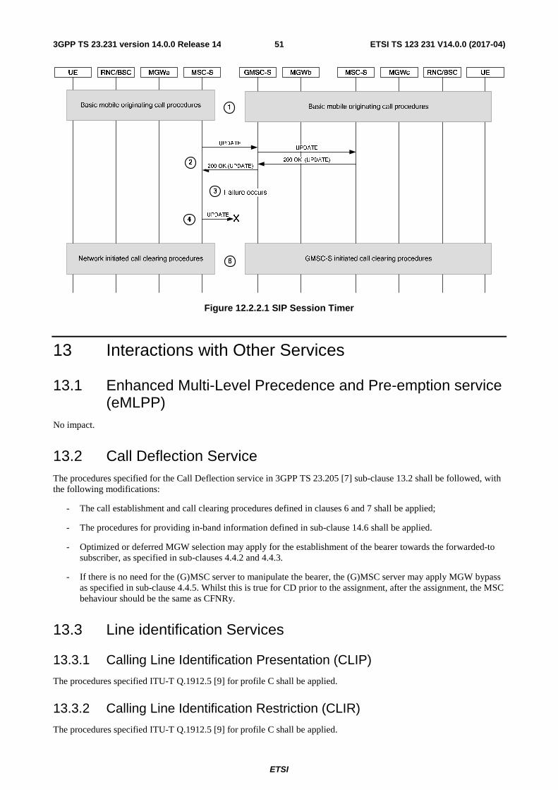
ETSI
ETSI TS 123 231 V14.0.0 (2017-04)513GPP TS 23.231 version 14.0.0 Release 14
Figure 12.2.2.1 SIP Session Timer
13 Interactions with Other Services
13.1 Enhanced Multi-Level Precedence and Pre-emption service (eMLPP)
No impact.
13.2 Call Deflection Service The procedures specified for the Call Deflection service in 3GPP TS 23.205 [7] sub-clause 13.2 shall be followed, with the following modifications:
- The call establishment and call clearing procedures defined in clauses 6 and 7 shall be applied;
- The procedures for providing in-band information defined in sub-clause 14.6 shall be applied.
- Optimized or deferred MGW selection may apply for the establishment of the bearer towards the forwarded-to subscriber, as specified in sub-clauses 4.4.2 and 4.4.3.
- If there is no need for the (G)MSC server to manipulate the bearer, the (G)MSC server may apply MGW bypass as specified in sub-clause 4.4.5. Whilst this is true for CD prior to the assignment, after the assignment, the MSC behaviour should be the same as CFNRy.
13.3 Line identification Services
13.3.1 Calling Line Identification Presentation (CLIP)
The procedures specified ITU-T Q.1912.5 [9] for profile C shall be applied.
13.3.2 Calling Line Identification Restriction (CLIR)
The procedures specified ITU-T Q.1912.5 [9] for profile C shall be applied.
ETSI
ETSI TS 123 231 V14.0.0 (2017-04)523GPP TS 23.231 version 14.0.0 Release 14
13.3.3 Connected Line Identification Presentation (COLP)
No impact.
13.3.4 Connected Line Identification Restriction (COLR)
No impact.
13.4 Call Forwarding Services
13.4.0 Principles
The procedures specified for Call Forwarding services in 3GPP TS 23.205 [7] sub-clause 13.4 shall be followed, with the following modifications:
- The call establishment and call clearing procedures defined in clauses 6 and 7 shall be applied;
- The procedures for providing in-band information defined in sub-clause 14.6 shall be applied.
- Failure handling in GMSC and MSC Server shall be supported as specified for basic mobile originating and terminating calls.
- Optimized or Deferred MGW selection may apply for the incoming side bearer establishment and for the establishment of the bearer towards the forwarded-to subscriber, as specified in sub-clauses 4.4.2 and 4.4.3.
- MGW bypass may apply if there is no need for the (G)MSC server to manipulate the bearer or insert inband information and if the call forwarding condition is detected before the incoming side bearer is established.
- The modifications specified in the following sub-clauses shall be applied.
The network model and message sequence specified in 3GPP TS 23.205 [7] sub-clause 13.4 also apply with the exception that the ISUP ACM/CPG messages are encapsulated within a SIP 183 Session Progress response.
13.4.1 Call Forwarding Unconditional (CFU)
See 3GPP TS 23.205 [7] sub-clause 13.4.1.
13.4.2 Call Forwarding on mobile subscriber Busy (CFB)
13.4.2.1 Network Determined User Busy (NDUB)
13.4.2.1.1 Initial INVITE
The MSC server shall indicate that preconditions have not been met if either of the following conditions is satisfied before sending the INVITE:
- the incoming INVITE indicated that the remote preconditions had not been met and no new SDP indicating otherwise had since been received, or
- MGW selection is required for this call and the incoming side RTP connection point has not been yet successfully reserved and configured in the MGW.
13.4.2.1.2 Confirmation of bearer establishment
If the outgoing INVITE indicated that preconditions are yet to be met, the new SDP indicating that the pre-conditions have now been satisfied will be sent when both following conditions are satisfied:
1. Either:

ETSI
ETSI TS 123 231 V14.0.0 (2017-04)533GPP TS 23.231 version 14.0.0 Release 14
a. The incoming INVITE indicated that the remote preconditions were yet to be satisfied, and new SDP indicating that these preconditions have been met has been received, or
b. The incoming INVITE did not include any preconditions information or indicated that remote preconditions had been met
and
2. Either
a. The incoming side RTP connection point has been successfully reserved and configured in the MGW.
b. MGW selection is not required for this call.
13.4.2.2 User Determined User Busy (UDUB)
See 3GPP TS 23.205 [7] sub-clause 13.4.2.2.
13.4.2.2.1 Initial INVITE
The MSC server shall indicate that preconditions have not been met if either of the following conditions is satisfied before sending the INVITE:
- the incoming INVITE indicated that the remote preconditions had not been met and no new SDP message indicating otherwise had since been received, or
- MGW selection is required for this call and the incoming side RTP connection point has not been yet successfully reserved and configured in the MGW.
NOTE: MGW selection may not be required for the call only if the UE is able to send the User Determined User Busy indication to the MSC Server before the subscriber is alerted.
13.4.2.2.2 Confirmation of bearer establishment
If the outgoing INVITE indicated that preconditions are yet to be met, the new SDP indicating that the pre-conditions have now been satisfied will be sent when both following conditions are satisfied:
1. Either:
a. The incoming INVITE indicated that the remote preconditions were yet to be satisfied, and new SDP indicating that these preconditions have been met has been received, or
b. The incoming INVITE did not include any preconditions information or indicated that remote preconditions had been met
and
2. Either
a. The incoming side RTP connection point has been successfully reserved and configured in the MGW.
b. MGW selection is not required for this call.
13.4.3 Call Forwarding on No Reply (CFNRy)
13.4.3.1 Initial INVITE
Following the possible generation of in-band information, the MSC server shall not include any preconditions in the INVITE message because the incoming side bearer has already been established.

ETSI
ETSI TS 123 231 V14.0.0 (2017-04)543GPP TS 23.231 version 14.0.0 Release 14
13.4.4 Call Forwarding on mobile subscriber Not Reachable (CFNRc)
13.4.4.1 Initial INVITE
The MSC server shall indicate that preconditions have not been met if either of the following conditions is satisfied before sending the INVITE:
- the incoming INVITE indicated that the remote preconditions had not been met and no new SDP message indicating otherwise had since been received, or
- MGW selection is required for this call and the incoming side RTP connection point has not been yet successfully reserved and configured in the MGW.
13.4.4.2 Confirmation of bearer establishment
If the outgoing INVITE indicated that preconditions are yet to be met, and new SDP indicating that the pre-conditions have now been satisfied will be sent when both following conditions are satisfied:
1. Either:
a. The incoming INVITE indicated that the remote preconditions were yet to be satisfied, and new SDP indicating that these preconditions have been met has been received, or
b. The incoming INVITE did not include any preconditions information or indicated that remote preconditions had been met
and
2. Either
a. The incoming side RTP connection point has been successfully reserved and configured in the MGW.
b. MGW selection is not required for this call.
13.5 Call Waiting (CW) The procedures specified for Call Waiting services in 3GPP TS 23.205 [7] sub-clause 13.5 shall be followed with the modifications:
- The procedures of "Hold request" for the Call Hold service in clause 13.6 applies for Existing call on hold.
- The call establishment and call clearing procedures defined in clauses 6 and 7 shall be applied.
13.6 Call Hold (CH)
13.6.1 Principles
The procedures specified for the Call Hold supplementary service in 3GPP TS 23.205 [7] sub-clause 13.6 shall be followed, with the following modifications:
- The call establishment and call clearing procedures defined in clauses 6 and 7 shall be applied;
- If an announcement is to be applied to the held party the procedures defined in sub-clause 14.6 shall be applied.
- The Call Hold service shall be supported through ISUP encapsulation and generation of SDP offer as specified by ITU-T Q.1912.5 [9] for profile C.
13.6.2 Hold Request
The SDP offer and encapsulated ISUP CPG message shall be sent within:

ETSI
ETSI TS 123 231 V14.0.0 (2017-04)553GPP TS 23.231 version 14.0.0 Release 14
- UPDATE message if Hold request occurred before answer (200 OK final response with encapsulated ANM);
- re-INVITE message if Hold request occurred after answer (200 OK final response with encapsulated ANM or CON).
The hold procedure shall be performed by changing the SDP attribute:
- "a=sendonly", if the stream was previously a sendrecv media stream;
- "a=inactive", if the stream was previously a recvonly media stream.
13.6.3 Retrieval Request
The SDP offer and encapsulated ISUP CPG message shall be sent within:
- UPDATE message if Retrieval request occurred before answer (200 OK final response with encapsulated ANM);
- re-INVITE message if Retrieval request occurred after answer (200 OK final response with encapsulated ANM or CON).
The retrieval procedure shall be performed by changing the SDP attribute:
- "a=sendrecv", if the stream was previously a sendonly media stream, or the attribute can be omitted, since sendrecv is the default;
- "a=recvonly", if the stream was previously an inactive media stream.
13.7 Multiparty (MPTY)
13.7.1 Introduction
The procedures specified for the Multi Party supplementary service in 3GPP TS 23.205 [7] sub-clause 13.7 shall be followed, with the following modifications:
- If the MGW only supports SIP-I associated Nb, the procedures for establishing the internal Nb bearer between the peripheral context and the Multiparty bridge context shall be in accordance with the standard SIP-I based Nc external bearer setup procedures. The Establish Bearer, Prepare Bearer, Tunnel Information Up and Tunnel Information Down procedures shall be replaced by the Reserve RTP Connection Point, Reserve and Configure RTP Connection Point, Configure RTP connection point.
- If the MGW supports combinations of SIP-I and BICC associated Nb, the MSC-S may establish the internal Nb bearer between the peripheral context and the Multiparty bridge following the standard SIP-I nased Nc or BICC based Nc external bearer setup procedures.
- The MSC-S knows whether the MGW supports SIP-I and/or BICC associated Nb through local configuration data.
- The hold and retrieval of users shall be encoded as described in Clause 13.6, with further clarifications in Clause 13.7.2.
NOTE1: If the MGW only supports BICC associated Nb, the procedures for establishing the internal Nb bearer between the peripheral context and the Multiparty bridge context are defined in 3GPP TS 23.205 [7].
NOTE2: Sub-clause 13.7.5 of 3GPP TS 23.205 [7] gives an example where the procedures for establishing the internal Nb bearer between the peripheral context and the Multiparty bridge context are in accordance with the standard external bearer setup procedures specified in BICC based Nc.
13.7.2 Beginning the Multi Party call
See 3GPP TS 23.205 [7] sub-clause 13.7.1.

ETSI
ETSI TS 123 231 V14.0.0 (2017-04)563GPP TS 23.231 version 14.0.0 Release 14
The CPG to inform an active user of the conference establishment shall be encoded in a SIP INFO.
For a user on hold, the following applies:
- A CPG to inform the user on hold of the conference establishment shall be sent.
- A CPG to retrieve the user on hold may be sent. The retrieval of the user on hold may also be combined with the conference call establishement in a single CPG.
- a re-INVITE to activate the held media shall be sent.
- If only a CPG to inform the user on hold of the conference establishment is sent, the re-INVITE shall encapsulate this CPG.
- If only a single CPG to inform the user on hold of the conference establishment and to retrieve the user on hold is sent, the re-INVITE shall encapsulate this CPG.
- If seperate CPGs to inform the user on hold of the conference establishment and to retrieve the user on hold are sent, the re-INVITE shall encapsulate the CPG to retrieve the user on hold. The CPG to inform the user on hold of the conference establishment shall be encapsulated in a SIP INFO.
13.7.3 Managing an active Multi Party call
See 3GPP TS 23.205 [7] sub-clause 13.7.2.
13.7.4 Disconnect
See 3GPP TS 23.205 [7] sub-clause 13.7.3.
13.7.5 Failure handling in MSC server
See 3GPP TS 23.205 [7] sub-clause 13.7.4.
13.7.6 Example 1
In this example, the procedures for establishing the internal Nb bearer between the peripheral context and the Multiparty bridge context are in accordance with the standard external bearer setup procedures specified for SIP-I based Nc.
Figure 13.7.6.1 shows the network model for multi party call. The "squared" line represents the call control signalling. The "dotted" line represents the bearer control signalling and the bearer. Note that for a TDM access there is no separation between the call and bearer control signalling. In the following example it is assumed that each party participating in the Multi Party conference is handled in a separate context representing the call leg between the Multi Party bridge and the Multi Party participant. The Multi Party bridge itself is handled in a separate context. This separation to several contexts is done in order to simplify interactions with other functionality, such as handover, even though other implementation options are not excluded.

ETSI
ETSI TS 123 231 V14.0.0 (2017-04)573GPP TS 23.231 version 14.0.0 Release 14
Figure 13.7.6.1: Multi Party call (Network model)
For the purposes of the information flow diagrams it is assumed that there are only two remote parties. Party A is the subscriber controlling the Multi Party service (served mobile subscriber). Party B is the held party and party C is the active party.
It is assumed that the Multi Party bridge is located in the MGW that has been selected for the served mobile subscriber.
Figure 13.7.6.2 shows the message sequence example for the beginning of multi party call. When the served mobile subscriber invokes a Multi Party service the MSC server requests the MGW to create a separate context for the Multi Party bridge. The MSC server seizes a bearer termination for each party in that context. In addition, each call leg is represented by a separate context. Therefore the parties in the active call will be split in separate contexts. The MSC server requests the MGW to create a new context and to move the bearer termination for the served mobile subscriber from the active call context to the new context. To connect the parties to the Multi Party bridge the MSC server requests the MGW to establish internal Nb connections with the PCM codec between the bearer terminations in the Multi Party bridge context and the call leg contexts, using the standard external bearer setup procedures of SIP-I based Nc. The held party is informed about the retrieval of the held call, and the both remote parties are informed about the multi party call establishment.
MSC-S
MGW
CTX MPTYTA0 TB0
TC0
RNC/BSC CTX A TA
CTX AB
TB1 TB
CTX AC TC1 TC
TA1 B-party
C party

ETSI
ETSI TS 123 231 V14.0.0 (2017-04)583GPP TS 23.231 version 14.0.0 Release 14
UE RNC/BSC MSC-S MGW
Multi Party req
Context ($) ADD.request ($) ADD.request ($) ADD.request ($)
Context (C MPTY) ADD.reply (TA0 ) ADD.reply (TB0) ADD.reply (TC0)
Context (C A) MOV.reply (TA )
Context ($) MOV.request (TA)
Context (C AB ) ADD.request ($)
Re-INVITE (a=sendrecv, CPG ConfCallEstabilished + retrieval) (to B) (Note)
Multi Party acknowledge
Context (C AB ) ADD.reply (TB1)
Context (C AC ) ADD.request ($)
Context (C AC ) ADD.reply (TC1)
INFO (CPG(ConfCallEstabilished) (to B) (Note)
Context (C A) ADD.reply (TA1)
Context (C A) ADD.request ($)
Reserve RTP Connection Point Reserve RTP Connection Point Reserve RTP Connection Point
Reserve and Configure RTP Connection Point
Reserve and Configure RTP Connection Point
Reserve and Configure RTP Connection Point
Context (CMPTY) MOD .request ( TA 0) B0 )
C0 )
MOD. request (TMOD .request ( T
Context (CMPTY) MOD.reply (TA0) MOD.reply (TB 0) . (TC0
)
Configure RTP Connection Point Configure RTP Connection Point Configure RTP Connection Point
MODreply
INFO (CPG(ConfCallEstabilished) (to C)
Note: See Clause 13.7.2. Figure 13.7.6.2: Information flow for multi party call, internal IP bearer (message sequence chart)
13.8 Closed User Group (CUG) No impact.
13.9 Advice of Charge (AoC) No impact.

ETSI
ETSI TS 123 231 V14.0.0 (2017-04)593GPP TS 23.231 version 14.0.0 Release 14
13.10 User-to-User Signalling (UUS) User to User signalling is supported through ISUP encapsulation, as specified by ITU-T Q.1912.5 [9].
13.11 Call Barring Services
13.11.1 Barring of outgoing calls
No impact.
13.11.2 Barring of incoming calls other than Anonymous Call Rejection
No impact.
13.11.3 Anonymous Call Rejection (ACR)
The call shall be handled as for other call barring procedures, with the additions as specified for the Anonymous Call Rejection service in 3GPP TS 23.205 [7] sub-clause 13.11.3 shall be followed, and with the following modifications:
- the procedures for providing in-band information defined in sub-clause 14.6 shall be applied;
- the GMSC Server shall send a 183 message with encapsulated ACM or CPG including cause no. 24 before applying the announcement;
- after the announcement has been completed, the GMSC server shall initiate the call clearing according to clause 7.
13.12 Explicit Call Transfer (ECT) The procedures specified in Clause 13.12 of 3GPP TS 23.205[7] shall be applied. The example service flow is as shown in the following sub-clause.
13.12.1 Example
Party A is the subscriber controlling the Explicit Call Transfer Call (served mobile subscriber). Party B is the first remote called party (held party). Party C is the second remote called party. MSC-A, MSC-B and MSC-C is the MSC server served for Party A, Party B and Party C respectively.
After a call between Party A with Party B has been established successfully and Party B is held, a new call between party A with Party C is established successfully. After getting the ECT request, MSC-A initiates the ECT service procedure by changing through the connection between Party B with Party C.
After receiving an ECT request from Party A UE, MSC-A shall retrieve Party B from hold by using a re-INVITE request and through-connection the bearer terminations between Party B and Party C. Additionally, MSC-A sends ECT notifications to MSC-B and MSC-C using INFO requests. Figure 13.12.1 is an example service flow diagram for the ECT service.
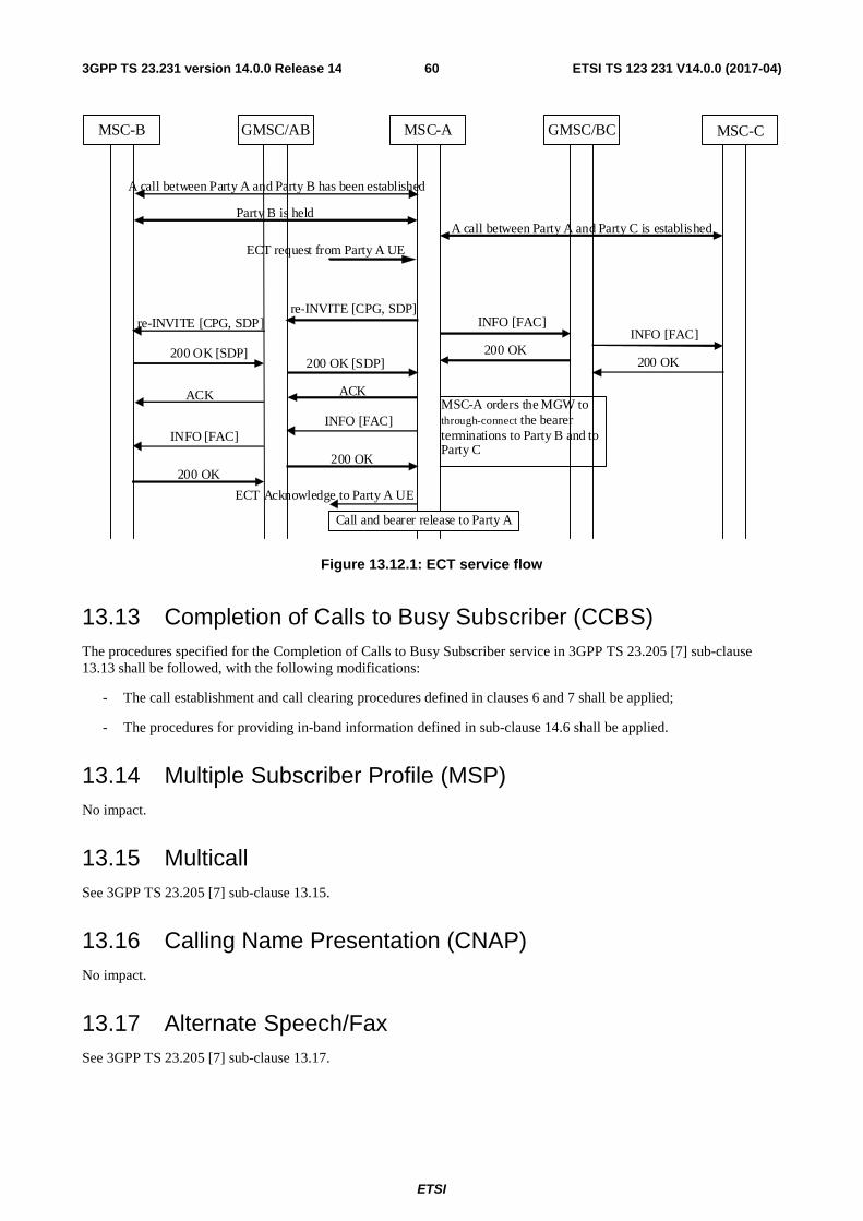
ETSI
ETSI TS 123 231 V14.0.0 (2017-04)603GPP TS 23.231 version 14.0.0 Release 14
GMSC/AB MSC-B MSC-A
ECT request from Party A UE
A call between Party A and Party C is established
ECT Acknowledge to Party A UE
re-INVITE [CPG, SDP]
GMSC/BC MSC-C
A call between Party A and Party B has been established
Party B is held
MSC-A orders the MGW to through-connect the bearer terminations to Party B and to Party C
INFO [FAC]
INFO [FAC]
200 OK [SDP]
ACK
200 OK
200 OK
INFO [FAC]
200 OK 200 OK [SDP]
ACK
INFO [FAC]
200 OK
re-INVITE [CPG, SDP]
Call and bearer release to Party A
Figure 13.12.1: ECT service flow
13.13 Completion of Calls to Busy Subscriber (CCBS) The procedures specified for the Completion of Calls to Busy Subscriber service in 3GPP TS 23.205 [7] sub-clause 13.13 shall be followed, with the following modifications:
- The call establishment and call clearing procedures defined in clauses 6 and 7 shall be applied;
- The procedures for providing in-band information defined in sub-clause 14.6 shall be applied.
13.14 Multiple Subscriber Profile (MSP) No impact.
13.15 Multicall See 3GPP TS 23.205 [7] sub-clause 13.15.
13.16 Calling Name Presentation (CNAP) No impact.
13.17 Alternate Speech/Fax See 3GPP TS 23.205 [7] sub-clause 13.17.
ETSI
ETSI TS 123 231 V14.0.0 (2017-04)613GPP TS 23.231 version 14.0.0 Release 14
13.18 Modification of the Access Bearer
13.18.1 Modification of Bearer Characteristics
See 3GPP TS 23.205 [7] sub-clause 13.18.1.
13.18.2 IWF Protocol Change
See 3GPP TS 23.205 [7] sub-clause 13.18.2.
13.19 GSM Fax See 3GPP TS 23.205 [7] sub-clause 13.19.
13.20 Voice group call service (VGCS), Voice broadcast service (VBS)
The procedures specified for the VGCS/VBS supplementary service in 3GPP TS 23.205 [7] sub-clause 13.20 shall be followed, with the following modifications:
- If the MGW only supports SIP-I associated Nb, the procedures for establishing the internal Nb bearer between the peripheral context and the VGCS Multiparty Bridge context shall be in accordance with the standard SIP-I based Nc external bearer setup procedures. The Establish Bearer and Prepare Bearer procedures shall be replaced by the Reserve RTP Connection Point, Reserve and Configure RTP Connection Point, Configure RTP connection point.
- If the MGW supports combinations of SIP-I and BICC associated Nb, the MSC-S may establish the internal Nb bearer between the peripheral context and the VGCS Multiparty Bridge context following the standard SIP-I based Nc or BICC based Nc external bearer setup procedures.
- The MSC-S knows whether the MGW supports SIP-I and/or BICC associated Nb through local configuration data.
NOTE: If the MGW only supports BICC associated Nb, the procedures for establishing the internal Nb bearer between the peripheral context and the VGCS Multiparty Bridge context are defined in 3GPP TS 23.205 [7].
14 Interactions with Other Network Features and Services
14.1 Customised Applications for Mobile network Enhanced Logic (CAMEL)
The procedures specified for Customised Applications for Mobile network Enhanced Logic (CAMEL) in 3GPP TS 23.205 [7] sub-clause 14.1 shall be followed, with the clarifications given in the following sub-clauses. The examples specified in 3GPP TS 23.205 [7] sub-clauses 14.6 also apply.
14.1.1 Play Announcement/Send Tone
The procedures specified for the Play Announcement/Send Tone in 3GPP TS 23.205 [7] sub-clause 14.1.1 shall be followed, with the following modifications:
- the procedures for providing tones or announcements and the procedures for stopping providing tones or announcements defined in sub-clause 14.6 shall be applied.

ETSI
ETSI TS 123 231 V14.0.0 (2017-04)623GPP TS 23.231 version 14.0.0 Release 14
14.1.2 User Interaction
The procedures specified for the User Interaction in 3GPP TS 23.205 [7] sub-clause 14.1.2 shall be followed, with the following modifications:
- the procedures for providing tones or announcements and the procedures for stopping providing tones or announcements defined in sub-clause 14.6 shall be applied.
- the procedures for detecting and reporting DTMF tones defined in sub-clause 14.4 shall be applied.
14.1.3 Call Party Handling (CPH)
See 3GPP TS 23.205 [7] sub-clause 14.1.3.
14.2 IST See 3GPP TS 23.205 [7] sub-clause 14.2 with the following modification:
- the (G)MSC server initiated call clearing procedures defined in clause 7 shall be applied.
14.3 Operator Determined Barring (ODB) The procedures specified for the Operator Determined Barring service in 3GPP TS 23.205 [7] sub-clause 14.3 shall be followed, with the following modifications:
- the call establishment and call clearing procedures defined in clauses 6 and 7 shall be applied;
- the procedures for providing in-band information defined in sub-clause 14.6 shall be applied.
- Optimized or deferred MGW selection may apply for the establishment of the incoming side bearer, as specified in sub-clauses 4.4.2 and 4.4.3.
14.4 DTMF
14.4.1 General
This clause only specifies the requirements to be supported for DTMF signalling on SIP-I based Nc. Interworking of DTMF between BICC and SIP-I on Nc and interworking between DTMF in external networks and SIP-I is specified in 3GPP TS 29.235 [21].
DTMF signalling via the RTP telephony-event according to IETF RFC 4733 [24] on Nb Interface shall be supported in SIP-I based Circuit Switched Core Network [y].
Inband DTMF signalling (generation, detection) shall also be supported in SIP-I based Nc to ensure open interoperability between two MSC servers from different vendors, when terminating MSC server selects PCM and does not offer RTP telephony-event in the answer.
When the negotiation for telephone events via the SDP offer-answer mechanism is complete and the needed preconditions defined in IETF RFC 3312 [26] are fulfilled, if RTP telephony-event has been successfully negotiated then telephone events can be sent in RTP payload. If a speech codec other than the default PCM codec has been selected (via the 3GPP SIP-I codec negotiation procedures, see 3GPP TS 23.153 [3]), DTMF shall be sent as an RTP Telephony Event. If the default PCM speech codec is selected, DTMF transport in the RTP telephony-event is optional. However, if the RTP telephony-event is included in the SDP answer, it shall be used to transport DTMF (rather than inband transport in the default PCM speech codec).
Interworking Procedures to external networks at the G-MSC server are specified in 3GPP TS 29.235 [21].

ETSI
ETSI TS 123 231 V14.0.0 (2017-04)633GPP TS 23.231 version 14.0.0 Release 14
14.4.2 DTMF handling in SIP-I Offer/Answer
(G)MSC Servers and MGWs shall support the reception and transmission of the RTP MIME type "telephone event" as defined in IETF RFC 4733 [24] and as per the following requirements:
- An MSC Server initiating an SDP offer shall include the MIME type "telephone events" with default events in the first SDP offer, if it offers any codecs other than the default PCM codec. An MSC Server initiating an SDP offer with only the default PCM codec as speech codec may include the MIME type "telephone events" in the first SDP offer,
- An MSC Server terminating an SDP offer shall accept the MIME type "telephone events" with default events in any SDP answer, if it selects any codec other than the default PCM codec. An MSC Server terminating an SDP offer that selects the default PCM codec as speech codec may include the MIME type "telephone events" in the SDP answer, if present in the SDP offer,
- A 3GPP SIP-I intermediate node receiving an SDP offer with the MIME type "telephone events" shall forward the MIME type "telephone-events" in the offer to the succeeding node.
14.4.3 Server to MGW Procedures
The (G)MSC Server indicates the transport mode of DTMF to the MGW as follows in the "Configure RTP Connection Point" procedure or "Reserve and Configure RTP Connection Point " procedure:
- The (G)MSC Server shall configure the RTP telephony event payload at the MGW if successfully negotiated in the SDP Offer/Answer.
- If the (G)MSC Server configures the RTP telephony event payload at the MGW for a given termination and applies the Detect DTMF procedure to request the detection of DTMF, the MGW shall detect DTMF within the RTP telephony event payload according to IETF RFC 4733 [24] and shall not detect inband DTMF within a speech codec.
- If the (G)MSC Server does not configures the RTP telephony event payload at the MGW for a given termination and applies the "Detect DTMF" procedure to request the detection of DTMF, the MGW shall detect inband DTMF within the speech codec; the (G)MSC Server shall not request "Detect DTMF" without RTP Telephony Event in combination with any codec other than the default PCM codec.
- If the (G)MSC Server configures the RTP telephony event payload at the MGW for a given termination and applies the Send DTMF procedure to request the sending of DTMF, the MGW shall send DTMF within the RTP telephony event payload according to IETF RFC 4733 [24].
- If the (G)MSC Server does not configure the RTP telephony event payload at the MGW for a given termination and applies the "Send DTMF" procedure to request the sending of DTMF, the MGW shall send inband DTMF within the speech codec; the (G)MSC Server shall not request "Send DTMF" without RTP Telephony Event in combination with any codec other than the default PCM codec.
- If the (G)MSC Server requests reporting of DTMF via "Detect DTMF" Procedure then when the MGW has reported a DTMF Digit Event the MGW shall not forward the DTMF to the succeeding interface as this could result in double detection of the same digit.
- If the (G)MSC Server has requested support of RTP Telephony Event via the "Configure RTP Connection Point" procedure or " Reserve and Configure RTP Connection Point " procedure but has not requested reporting of DTMF digits via the "Detect DTMF" procedure the MGW shall forward received RTP Telephony Events to succeeding/preceding interface for a connection that is configured to support RTP Telephony Event.
- If the (G)MSC Server does not wish to receive DTMF (has not configured "DTMF Detect") but has requested support of RTP Telephony Event via the "Configure RTP Connection Point" procedure or " Reserve and Configure RTP Connection Point " procedure at one bearer termination but not at the other bearer termination, if the other termination is default PCM MGW shall then relay DTMF (see clauses 14.4.8 and 14.4.9).

ETSI
ETSI TS 123 231 V14.0.0 (2017-04)643GPP TS 23.231 version 14.0.0 Release 14
14.4.4 RTP Telephony Event DTMF Digit Generation
14.4.4.1 General
The RTP Telephony Event DTMF digit generation shall be performed in accordance with IETF RFC 4733 [24]. The following clauses describe the additional requirements for the bearer independent CS core network.
14.4.4.2 Start DTMF
When the MSC server receives the Start DTMF message from the UE, it shall use the Send DTMF procedure to request the MGW to modify the bearer termination to transmit the requested digit.
14.4.4.3 Stop DTMF
When the MSC server receives the Stop DTMF message from the UE, it shall use the Stop DTMF procedure to request the MGW to modify the bearer termination to stop digit transmission.
Upon reception of the Stop DTMF procedure, the MGW shall ensure the minimum digit duration is kept, in accordance with 3GPP TS 23.014 [27] and then terminate the digit transmission by sending RTP Telephony Event with "End-bit" set to YES.
If implicit DTMF timing is deployed (as shown in example figure 14.4.4.3.1) and the MGW has already completed the digit transmission it shall not take any action upon the reception of the Stop DTMF procedure.
14.4.4.4 Example
When the UE sends Start DTMF and Stop DTMF messages, the MSC server uses resources in the MGW to transmit a digit by modifying the bearer termination.
Ue MSC-S MGW
Context (Cx) 1
Start DTMF (Digit) MOD. Request [RTP Tel Event, signal = Digit] (Tx)
MOD. Reply (Tx)
Send DTMF Procedure
Start DTMF AckContext (Cx)
Context (Cx) 2
Stop DTMF (Digit) MOD. Request [RTP Tel Event, stop signal] (Tx)
MOD. Reply (Tx)
Stop DTMF Procedure
Stop DTMF AckContext (Cx)
RTP Telephony Event [Digit=digit, Ebit=0]
Figure 14.4.4.4.1: DTMF Digit generation - implicit timing over RTP Telephony Event (message sequence chart)
14.4.5 DTMF Tone Generation
DTMF Tone Generation shall only occur if the RTP Telephony Event has not been negotiated and the default PCM codec is selected for the user plane. The MSC Server shall apply the "Send DTMF" procedure to the core network side termination (PCM) in accordance with 3GPP TS 23.205 [7] Clause 14.4.1.1

ETSI
ETSI TS 123 231 V14.0.0 (2017-04)653GPP TS 23.231 version 14.0.0 Release 14
14.4.6 RTP Telephony Event DTMF Digit Detection
14.4.6.1 General
The RTP Telephony Event DTMF digit detection shall be performed in accordance with IETF RFC 4733 [24]. The following clauses describe the additional requirements for the bearer independent CS core network.
14.4.6.2 Detect DTMF Digit
An MSC server uses the Detect DTMF procedure to request a MGW to report DTMF Digits. If a MGW receives the Detect DTMF procedure, it shall configure the bearer termination to receive DTMF digits. The result of the digit detection shall be reported within Notify DTMF Digit procedure.
The Detect DTMF procedure permits the MSC Server to request reporting either of Start and End of DTMF detection, or only of End of DTMF Detection. The support of "start of DTMF detection" is optional for the MGW; if not supported the MGW shall indicate the appropriate error code.
If the MSC Server does not request DTMF notification then the MGW shall relay the DTMF to the succeeding interface.
14.4.6.3 Example – DTMF Notification
MGW MSC-S MGW
Context (Cx) 1
RTP Telephony Event [(Digit), E-bit = 0, Duration = x]
MOD. Request [RTP Tel Event, Event = StartTone,
EndTone] (Tx)
MOD. Reply (Tx)
Detect DTMF Digit via RTP Tel Event, (start
DTMF and StopDTMF)Context (Cx)
Context (Cx) 2 Notify.Request [Report DTMF, start tone, Digit]
(Tx)Notify. Reply (Tx)
Report start of DTMF Digit
Context (Cx)
RTP Telephony Event [(Digit), E-bit = 1, Duration = y]
Context (Cx) 3 Notify.Request [Report DTMF, end tone, Digit]
(Tx)Notify. Reply (Tx)
Report end of DTMF Digit
Context (Cx)
Figure 14.4.6.3.1: DTMF Notification with both start and end events
ETSI
ETSI TS 123 231 V14.0.0 (2017-04)663GPP TS 23.231 version 14.0.0 Release 14
MGW MSC-S MGW
Context (Cx) 1
RTP Telephony Event [(Digit), E-bit = 0, Duration = x]
MOD. Request [RTP Tel Event, Event = EndTonel]
(Tx)
MOD. Reply (Tx)
Detect DTMF Digit via RTP Tel Event, (End
DTMF only)Context (Cx)
start of DTMF Digit received, waits for E-bit=1
RTP Telephony Event [(Digit), E-bit = 1, Duration = y]
Context (Cx) 2 Notify.Request [Report DTMF, end tone, Digit]
(Tx)Notify. Reply (Tx)
Report end of DTMF Digit
Context (Cx)
Figure 14.4.6.3.2: DTMF Notification with only end DTMF event
14.4.7 Inband DTMF Tone Detection
DTMF tone detection within the PCM speech codec as specified by Clause 14.4.2.1 of 3GPP TS 23.205 [7] shall only be required by applications making use of the DTMF information within the (G)MSC server, and only if the RTP telephony event is not negotiated with SDP offer/answer.
A server controlling a MGW requests detection of inband DTMF by applying the Detect DTMF procedure but not configuring the RTP Telephony Event payload at the corresponding termination.
14.4.8 Interworking between RTP Telephony Events and Inband DTMF Tones
A (G)MSC Server or Interworking Node may need to interwork a SIP-I associated bearer where the usage of RTP Telephony Event has been negotiated with a bearer where PCM encoded speech but no RTP Telephony Event has been negotiated. The MGW shall relay the DTMF between the terminations of a context if the following conditions apply:
- the (G)MSC Server or Interworking Node configures a MGW with SIP-I associated bearer termination to support RTP Telephony Event from/to the preceding node and;
- the (G)MSC Server has not requested DTMF detection to be reported and;
- the selected codec to the succeeding node is default PCM and;
- the succeeding SIP-I node has not selected RTP Telephony Event.
RTP Telephony events received on SIP-I associated bearer are inserted into the PCM stream (bullet 2 in Figure 14.4.8.1). Inband DTMF received from the preceding node shall be inserted as RTP Telephony events on succeeding bearer termination (bullet 3 in Figure 14.4.8.1).
When detecting inband DTMF the MGW shall ensure the minimum duration for valid DTMF validation is detected in accordance with 3GPP TS 23.014 [27] before signalling an RTP telephony Event.

ETSI
ETSI TS 123 231 V14.0.0 (2017-04)673GPP TS 23.231 version 14.0.0 Release 14
MGW MSC-S MGW
Context (Cx)
1
RTP Telephony Event [(Digit), Duration = x]
MOD. Request [RTP Tel Event payload Type] (Tx)
MOD. Reply (Tx)Context (Cx)
Insert DTMF Tone into payload
2
MGWSIP-I Nc/Nb
SIP-I node that does not support RTP Telephony
Event
MSC-S
RTP Telephony Event [(Digit), Duration = y]
Detect DTMF Tone in payload
3
Figure 14.4.8.1: DTMF Relay between RTP Telephony Event and inband DTMF
14.5 OR The procedures specified for Optimal Routeing network service in 3GPP TS 23.205 [7] sub-clause 14.5 shall be followed with the following modification:
- the procedures for call clearing defined in sub-clause 7 shall be applied.
14.6 Providing tones or announcements
14.6.1 Introduction
The procedures specified for providing tones or announcements in 3GPP TS 23.205 [7] sub-clause 14.6 shall be followed, with the clarifications given in the following sub-clauses. The examples specified in 3GPP TS 23.205 [7] sub-clauses 14.6 also apply.
14.6.2 Preconditions when providing in-band information to the calling subscriber
For a mobile terminating/forwarded call, announcements/tones may be provided to the calling subscriber only when the following conditions are satisfied:
1. Either:
a. The incoming INVITE(IAM) indicated that remote preconditions had not been met, and new SDP has been received indicating that preconditions have been met, or
b. The incoming INVITE(IAM) did not include any preconditions information or indicated that remote preconditions had been met;
and
2. The incoming side RTP connection point has been successfully reserved and configured in the MGW.

ETSI
ETSI TS 123 231 V14.0.0 (2017-04)683GPP TS 23.231 version 14.0.0 Release 14
For a mobile originating call, the traffic channel assignment shall be completed before providing the in-band information to the calling subscriber.
14.6.3 Preconditions when providing in-band information to the called subscriber
The called party is selected by the calling party, or a supplementary service (call forwarding, call deflection, CAMEL redirection etc), or a call is initiated by the gsmSCF using the Initiate Call Attempt procedure. The called party may also be in the PSTN.
Announcements/tones may be provided to the called subscriber only when the following conditions are satisfied:
1. The called party has answered and is still active in the call, and
2. The outgoing side RTP Connection point has been successfully reserved and configured in the MGW.
14.6.4 Preconditions when providing in-band information to multiple subscribers
See 3GPP TS 23.205 [7] sub-clause 14.6.3.
14.6.5 Request to play an announcement/tone
See 3GPP TS 23.205 [7] sub-clause 14.6.4.
14.6.6 Stopping an announcement/tone
See 3GPP TS 23.205 [7] sub-clause 14.6.5.
14.6.7 Announcement/tone completed
See 3GPP TS 23.205 [7] sub-clause 14.6.6.
14.7 Global Text Telephony Global Text Telephony shall be supported as described in 3GPP TS 23.205 [7] Clause 14.7 where the CTM package properties are included in the "Reserve RTP Connection Point" and "Configure RTP Connection Point" for Access side terminations and default PCM codec selected for the Core Network side terminations.
14.8 Emergency Calls Emergency Calls shall be handled as in clause 6.1 Basic Mobile Originating Call and clause 6.2 Basic Mobile Terminating Call. The Procedure Emergency Call Indication may be used for informing the MGW about the emergency call.
14.9 Subscriber and equipment trace See 3GPP TS 23.205 [7] sub-clause 14.9.
14.10 Customized Alerting Tones
14.10.1 General
See 3GPP TS 23.205 [7] sub-clause 14.10.1.

ETSI
ETSI TS 123 231 V14.0.0 (2017-04)693GPP TS 23.231 version 14.0.0 Release 14
14.10.2 Audio CAT
See 3GPP TS 23.205 [7] sub-clause 14.10.2.
14.10.3 Multimedia CAT
See 3GPP TS 23.205 [7] sub-clause 14.10.3.
15 Messages/Procedures and their contents
15.1 Messages between (G)MSC servers Table 15.1.1 lists the SIP methods that shall be supported between (G)MSC servers on Nc interface. Amendments and Endorsements to the referenced specifications are specified in 3GPP TS 29.231[4].
Table 15.1.1: Messages between (G)MSC servers
SIP method Reference INVITE RFC 3261 [15]
ACK RFC 3261 [15] BYE RFC 3261 [15]
CANCEL RFC 3261 [15] OPTIONS RFC 3261 [15]
INFO RFC 2976 [17] UPDATE RFC 3311 [18] PRACK RFC 3262 [19]
15.2 Procedures between (G)MSC server and MGW
15.2.1 Generic Mc Interface Procedures
Table 15.2.1.1 below indicates the procedures used between the (G)MSC server and the MGW in the Mc interface. These procedures are defined in Clause 16.2 of 3GPP TS 23.205 [7].

ETSI
ETSI TS 123 231 V14.0.0 (2017-04)703GPP TS 23.231 version 14.0.0 Release 14
Table 15.2.1.1: Required procedures defined in 3GPP TS 23.205 [7]

ETSI
ETSI TS 123 231 V14.0.0 (2017-04)713GPP TS 23.231 version 14.0.0 Release 14
Procedure defined in 3GPP TS 23.205 [7] Remarks Change Flow Direction NOTE 1 in that Clause is replaced by the following Note:
NOTE 1: This procedure may be combined with the "Reserve RTP Connection Point" procedure, the "Configure RTP Connection Point" procedure, the "Reserve and Configure RTP Connection Point" procedure, the "Prepare Bearer" procedure, the "Reserve Circuit" procedure, the "Join Bearer Termination" procedure, or the "Isolate Bearer Termination" procedure.
Join Bearer Termination Isolate Bearer Termination Prepare Bearer This procedure is not applicable for terminations towards a 3GPP
SIP-I based circuit-switched core network, but it is applicable for terminations toward an Iu-CS interface with ATM transport, or to seize internal terminations in a MGW, e.g. for conferencing scenarios or for VGCS. The optional "Tunnel Support" Information element is not applicable.
Reserve Circuit Change Through-Connection The NOTE in that Clause is replaced by the following Note:
NOTE: This procedure may be combined with the "Reserve RTP Connection Point" procedure, the "Configure RTP Connection Point" procedure, the "Reserve and Configure RTP Connection Point" procedure, the "Prepare Bearer" procedure, the "Reserve Circuit" procedure, the "Join Bearer Termination" procedure, or the "Isolate Bearer Termination" procedure.
Activate Interworking Function Bearer Released Release Termination Send Tone Stop Tone Play Announcement Stop Announcement Announcement Completed Tone Completed Detect DTMF The NOTE in that Clause is replaced by the following Note:
NOTE: This procedure may be combined with the "Reserve RTP Connection Point" procedure, the "Configure RTP Connection Point" procedure, the "Reserve and Configure RTP Connection Point" procedure, the "Prepare Bearer" procedure, the "Reserve Circuit" procedure.
Stop DTMF Detection Report DTMF Send DTMF Stop DTMF MGW Out-of-Service/ Maintenance locking MGW Communication Up MGW Restoration MGW Register MGW Re-register (G)MSC Server Ordered Re-register (G)MSC Server Restoration (G)MSC Server Out of Service Termination Out-of-Service Termination Restoration Audit Value Audit Capability Capability Update Command Reject Activate Voice Processing Function Modify Bearer Characteristics This procedure is not applicable for terminations towards a 3GPP
SIP-I based circuit-switched core network, but it is applicable for terminations toward an Iu-CS or A interface.
IWF Protocol Indication
ETSI
ETSI TS 123 231 V14.0.0 (2017-04)723GPP TS 23.231 version 14.0.0 Release 14
MGW Resource Congestion Handling – Activate MGW Resource Congestion Handling – Indication Bearer Modification Support This procedure is not applicable for terminations towards a 3GPP
SIP-I based circuit-switched core network, but it is applicable for terminations toward an Iu-CS interface.
CTM report Prepare IP Transport Modify IP Transport Address Emergency Call Indication Trace Activation Trace Deactivation Trace Activation result notification Continuity Check Tone Continuity Check Verify Continuity Check Response Rate Change Bearer Modified This procedure is not applicable for terminations towards a 3GPP
SIP-I based circuit-switched core network, but it is applicable for terminations toward an Iu-CS interface with ATM transport.
Bearer Modification Failed This procedure is not applicable for terminations towards a 3GPP SIP-I based circuit-switched core network, but it is applicable for terminations toward an Iu-CS interface with ATM transport.
Termination heartbeat indication Inactivity timeout activation Inactivity timeout indication Reserve RTP Connection Point Configure RTP Connection Point Reserve and Configure RTP Connection Point
15.2.2 SIP-I Specific Mc Interface Procedures
The clauses below indicate the procedures used between the (G)MSC server and the MGW in the Mc interface that are specific for a SIP-I based Nc network.
The procedures are logical, i.e. message identifiers are not part of the protocol. Several logical procedures can be combined into one H.248 command in order to perform required transactions. If several logical procedures are combined into one H.248 command, only one context/context request and only one bearer termination/bearer termination request is sent in the H.248 command.
All the procedures below describe a successful operation. If the procedure is rejected, a Command Reject is sent back to the entity that sent the command request.
Each Information Element, IE, is marked as (M) Mandatory, (C) Conditional or (O) Optional. A mandatory information element shall always be present. A conditional information shall be present if certain conditions are fulfilled; if those conditions are not fulfilled it shall be absent. An optional information element may be present or absent, at the discretion of the application at the sending entity. This categorisation is a functional classification, i.e., stage 2 information and not a stage 3 classification to be used for the protocol.
The stage 2 and stage 3 message and information element names are not necessarily identical.
16 Bearer Redirect Bearer Redirect is not supported within this 3GPP Release.
17 (G)MSC MGW Tandeming For (G)MSC MGW Tandeming, the procedures specified in the clause 18 of 3GPP TS 23.205 [7] shall apply.

ETSI
ETSI TS 123 231 V14.0.0 (2017-04)733GPP TS 23.231 version 14.0.0 Release 14
18 Timers for SIP-I based CS core network The Start_Bearer_Establishment Timer, as defined in 3GPP TS 23.205 [7], shall apply to a SIP-I based CS core network.
Timer functionality and procedures defined within ITU-T Q.1912.5 [9] Profile C shall apply to a SIP-I based CS core network.
19 Multiple IP Realms Multiple IP realms are supported as specified in 3GPP TS 23.205 [7].

ETSI
ETSI TS 123 231 V14.0.0 (2017-04)743GPP TS 23.231 version 14.0.0 Release 14
Annex A (informative): Change history
Change history Date TSG # TSG Doc. CR R
ev
Subject/Comment Old New
2008-06 CT#40 CP-080245 V2.0.0 approved in CT#40 2.0.0 8.0.0 2008-09 CT#41 CP-080464 0005 1 MGW selection procedures impacts on Call Forwarding services 8.0.0 8.1.0 0006 MGW selection procedures impacts on Call Deflection service 0007 MGW selection procedures impacts on ODB 0008 1 Global Text Telephony for SIP-I on Nc 0009 1 IP interface type indicator 0010 1 Call Hold Service 0011 1 Bearer Establishment for Multiparty Bearers 0012 CS Data and Facsimile Updates 0014 Clarifications for Multiparty service 2008-12 CT#42 CP-080697 0019 Call Clearing for A Interface on IP 8.1.0 8.2.0 CP-080697 0020 1 BSS Internal Handover procedure CP-080695 0021 1 Multimedia CAT in the CS domain CP-080697 0024 AoIP Impacts for Handover/Relocation CP-080686 0025 1 Telephone Numbering Schemes for a SIP-I based Nc Network CP-080686 0027 Usage of SIP Resource-Priority header for eMLPP service CP-080686 0028 Usage of re-INVITE without SDP for ECT Service CP-080686 0029 1 Impacts for MSP, VGCS, VBS within a SIP-I based Nc network CP-080697 0030 Usage of IP Interface Type within a SIP-I based Nc Network CP-080686 0031 Support of Bearer Redirect within a SIP-I based Nc network CP-080686 0018 3 Call Release CP-080686 0032 1 Data Calls CP-080686 0033 2 Call Clearing procedures at G-MSC 2009-03 CT#43 CP-090029 0035 1 G-MSC Procedures for Call Release- long variant 8.2.0 8.3.0 2009-06 CT#44 CP-090307 0036 Customised Alerting Tones 8.3.0 8.4.0 CP-090306 0039 1 MGW selection Context and Termination correction CP-090306 0040 1 Corrections to Deferred MGW Selection 2009-12 - - - - Update to Rel-9 version (MCC) 8.4.0 9.0.0 2011-03 CT#51 CP-110069 0041 1 Deferred MGW selection 9.0.0 10.0.0 0042 1 Introduction of LCLS 2011-09 CT#53 CP-110585 0044 1 Addition of Anonymous Call Rejection in the CS layered
architecture 10.0.0 11.0.0
2011-12 CT#53 CP-110814 0045 1 11.0.0 11.1.0 2012-11 Change history table corrected. 11.1.0 11.1.1 2013-12 CT#62 CP-130641 0046 1 GERAN Iu Mode 11.1.1 12.0.0 2015-12 CT#70 - - - Update to Rel-13 version (MCC) 12.0.0 13.0.0 2017-03 CT#75 - - - Update to Rel-14 version (MCC) 13.0.0 14.0.0

ETSI
ETSI TS 123 231 V14.0.0 (2017-04)753GPP TS 23.231 version 14.0.0 Release 14
History
Document history
V14.0.0 April 2017 Publication