ts 124 109 - v14.0.0 - universal mobile telecommunications ... · etsi 3gpp ts 24.109 version...
TRANSCRIPT

ETSI TS 124 109 V14.0.0 (2017-05)
Universal Mobile Telecommunications System (UMTS); LTE;
Bootstrapping interface (Ub) and network application function interface (Ua);
Protocol details (3GPP TS 24.109 version 14.0.0 Release 14)
TECHNICAL SPECIFICATION

ETSI
ETSI TS 124 109 V14.0.0 (2017-05)13GPP TS 24.109 version 14.0.0 Release 14
Reference RTS/TSGC-0124109ve00
Keywords LTE,UMTS
ETSI
650 Route des Lucioles F-06921 Sophia Antipolis Cedex - FRANCE
Tel.: +33 4 92 94 42 00 Fax: +33 4 93 65 47 16
Siret N° 348 623 562 00017 - NAF 742 C
Association à but non lucratif enregistrée à la Sous-Préfecture de Grasse (06) N° 7803/88
Important notice
The present document can be downloaded from: http://www.etsi.org/standards-search
The present document may be made available in electronic versions and/or in print. The content of any electronic and/or print versions of the present document shall not be modified without the prior written authorization of ETSI. In case of any
existing or perceived difference in contents between such versions and/or in print, the only prevailing document is the print of the Portable Document Format (PDF) version kept on a specific network drive within ETSI Secretariat.
Users of the present document should be aware that the document may be subject to revision or change of status. Information on the current status of this and other ETSI documents is available at
https://portal.etsi.org/TB/ETSIDeliverableStatus.aspx
If you find errors in the present document, please send your comment to one of the following services: https://portal.etsi.org/People/CommiteeSupportStaff.aspx
Copyright Notification
No part may be reproduced or utilized in any form or by any means, electronic or mechanical, including photocopying and microfilm except as authorized by written permission of ETSI.
The content of the PDF version shall not be modified without the written authorization of ETSI. The copyright and the foregoing restriction extend to reproduction in all media.
© European Telecommunications Standards Institute 2017.
All rights reserved.
DECTTM, PLUGTESTSTM, UMTSTM and the ETSI logo are Trade Marks of ETSI registered for the benefit of its Members. 3GPPTM and LTE™ are Trade Marks of ETSI registered for the benefit of its Members and
of the 3GPP Organizational Partners. oneM2M logo is protected for the benefit of its Members
GSM® and the GSM logo are Trade Marks registered and owned by the GSM Association.
ETSI
ETSI TS 124 109 V14.0.0 (2017-05)23GPP TS 24.109 version 14.0.0 Release 14
Intellectual Property Rights IPRs essential or potentially essential to the present document may have been declared to ETSI. The information pertaining to these essential IPRs, if any, is publicly available for ETSI members and non-members, and can be found in ETSI SR 000 314: "Intellectual Property Rights (IPRs); Essential, or potentially Essential, IPRs notified to ETSI in respect of ETSI standards", which is available from the ETSI Secretariat. Latest updates are available on the ETSI Web server (https://ipr.etsi.org/).
Pursuant to the ETSI IPR Policy, no investigation, including IPR searches, has been carried out by ETSI. No guarantee can be given as to the existence of other IPRs not referenced in ETSI SR 000 314 (or the updates on the ETSI Web server) which are, or may be, or may become, essential to the present document.
Foreword This Technical Specification (TS) has been produced by ETSI 3rd Generation Partnership Project (3GPP).
The present document may refer to technical specifications or reports using their 3GPP identities, UMTS identities or GSM identities. These should be interpreted as being references to the corresponding ETSI deliverables.
The cross reference between GSM, UMTS, 3GPP and ETSI identities can be found under http://webapp.etsi.org/key/queryform.asp.
Modal verbs terminology In the present document "shall", "shall not", "should", "should not", "may", "need not", "will", "will not", "can" and "cannot" are to be interpreted as described in clause 3.2 of the ETSI Drafting Rules (Verbal forms for the expression of provisions).
"must" and "must not" are NOT allowed in ETSI deliverables except when used in direct citation.
ETSI
ETSI TS 124 109 V14.0.0 (2017-05)33GPP TS 24.109 version 14.0.0 Release 14
Contents
Intellectual Property Rights ................................................................................................................................ 2
Foreword ............................................................................................................................................................. 2
Modal verbs terminology .................................................................................................................................... 2
Foreword ............................................................................................................................................................. 6
1 Scope ........................................................................................................................................................ 7
2 References ................................................................................................................................................ 7
3 Definitions and abbreviations ................................................................................................................... 8
3.1 Definitions .......................................................................................................................................................... 8
3.2 Abbreviations ..................................................................................................................................................... 9
4 Generic Bootstrapping Architecture; Ub interface ................................................................................. 10
4.1 Introduction ...................................................................................................................................................... 10
4.2 Bootstrapping procedure .................................................................................................................................. 11
4.3 User authentication failure ............................................................................................................................... 12
4.4 Network authentication failure ......................................................................................................................... 12
4.5 Synchronization failure .................................................................................................................................... 12
4A Generic Bootstrapping Achitecture Push; Upa ....................................................................................... 12
4A.1 Introduction ...................................................................................................................................................... 12
4A.2 Bootstrapping procedure .................................................................................................................................. 13
4A.3 User authentication failure ............................................................................................................................... 14
4A.4 Network authentication failure ......................................................................................................................... 14
4A.5 Synchronization failure .................................................................................................................................... 14
5 Network application function; Ua interface ........................................................................................... 14
5.1 Introduction ...................................................................................................................................................... 14
5.2 HTTP Digest authentication ............................................................................................................................. 14
5.2.1 General ........................................................................................................................................................ 14
5.2.2 Authentication procedure ............................................................................................................................ 15
5.2.2.1 General .................................................................................................................................................. 15
5.2.3 Authentication failures ................................................................................................................................ 16
5.2.4 Bootstrapping required indication ............................................................................................................... 16
5.2.5 Bootstrapping renegotiation indication ....................................................................................................... 16
5.2.6 Integrity protection ..................................................................................................................................... 16
5.3 UE and NAF authentication using HTTPS ....................................................................................................... 16
5.3.1 General ........................................................................................................................................................ 16
5.3.2 Shared key-based UE authentication with certificate-based NAF authentication ....................................... 17
5.3.2.1 Authentication procedure ...................................................................................................................... 17
5.3.2.2 Authentication failures .......................................................................................................................... 17
5.3.2.3 Bootstrapping required indication ......................................................................................................... 18
5.3.2.4 Bootstrapping renegotiation indication ................................................................................................. 18
5.3.3 Shared key-based mutual authentication between UE and NAF ................................................................ 18
5.3.3.1 Authentication procedure ...................................................................................................................... 18
5.3.3.2 Authentication failures .......................................................................................................................... 19
5.3.3.3 Bootstrapping required indication ......................................................................................................... 19
5.3.3.4 Bootstrapping renegotiation indication ................................................................................................. 19
5.3.4 Certificate based mutual authentication between UE and application server ............................................. 19
5.3.5 Integrity protection ..................................................................................................................................... 20
6 PKI portal, Ua interface.......................................................................................................................... 20
6.1 Introduction ...................................................................................................................................................... 20
6.2 Subscriber certificate enrolment ....................................................................................................................... 20
6.2.1 Enrolment procedure................................................................................................................................... 20
6.2.2 WIM specific authentication code for key generation ................................................................................ 22
6.2.3 WIM specific authentication code for proof of key origin .......................................................................... 22
6.2.4 Error situations ............................................................................................................................................ 23

ETSI
ETSI TS 124 109 V14.0.0 (2017-05)43GPP TS 24.109 version 14.0.0 Release 14
6.3 CA certificate delivery ..................................................................................................................................... 23
6.3.1 CA certificate delivery procedure ............................................................................................................... 24
6.3.2 Error situations ............................................................................................................................................ 24
7 Authentication Proxy .............................................................................................................................. 25
7.1 Introduction ...................................................................................................................................................... 25
7.2 Authentication .................................................................................................................................................. 26
7.3 Authorization .................................................................................................................................................... 26
Annex A (informative): Signalling flows of bootstrapping procedure ............................................... 27
A.1 Scope of signalling flows ....................................................................................................................... 27
A.2 Introduction ............................................................................................................................................ 27
A.2.1 General ............................................................................................................................................................. 27
A.2.2 Key required to interpret signalling flows ........................................................................................................ 27
A.3 Signalling flows demonstrating a successful bootstrapping procedure .................................................. 27
A.4 Signalling flows demonstrating a synchronization failure in the bootstrapping procedure ................... 31
Annex A1 (informative): Signalling flows of GBA Push procedure..................................................... 34
A1.1 Scope of signalling flows ....................................................................................................................... 34
A1.2 Introduction ............................................................................................................................................ 34
A1.2.1 General ............................................................................................................................................................. 34
A1.2.2 Key required to interpret signalling flows ........................................................................................................ 34
A1.3 Signalling flows demonstrating a successful GBA Push procedure ....................................................... 34
Annex B (informative): Signalling flows for HTTP Digest Authentication with bootstrapped security association ........................................................................................ 37
B.1 Scope of signalling flows ....................................................................................................................... 37
B.2 Introduction ............................................................................................................................................ 37
B.2.1 General ............................................................................................................................................................. 37
B.2.2 Key required to interpret signalling flows ........................................................................................................ 37
B.3 Signalling flows demonstrating a successful authentication procedure ................................................. 37
Annex C (normative): XML Schema Definition ................................................................................ 42
C.1 Introduction ............................................................................................................................................ 42
Annex D (informative): Signalling flows for Authentication Proxy ................................................... 43
D.1 Scope of signalling flows ....................................................................................................................... 43
D.2 Introduction ............................................................................................................................................ 43
D.2.1 Key required to interpret signalling flows ........................................................................................................ 43
D.3 Signalling flow demonstrating a successful authentication procedure ................................................... 43
Annex E (informative): Signalling flows for PKI portal ..................................................................... 49
E.1 Scope of signalling flows ....................................................................................................................... 49
E.2 Introduction ............................................................................................................................................ 49
E.2.1 General ............................................................................................................................................................. 49
E.2.2 Key required to interpret signalling flows ........................................................................................................ 49
E.3 Signalling flows demonstrating a successful subscriber certificate enrolment ...................................... 49
E.3.1 Simple subscriber certificate enrolment ........................................................................................................... 49
E.3.2 Subscriber certificate enrolment with WIM authentication codes .................................................................... 53
E.4 Signalling flows demonstrating a failure in subscriber certificate enrolment ........................................ 60
E.5 Signalling flows demonstrating a successful CA certificate delivery .................................................... 60

ETSI
ETSI TS 124 109 V14.0.0 (2017-05)53GPP TS 24.109 version 14.0.0 Release 14
E.6 Signalling flows demonstrating a failure in CA certificate delivery ...................................................... 64
Annex F (informative): Signalling flows for PSK TLS with bootstrapped security association ..... 65
F.1 Scope of signalling flows ....................................................................................................................... 65
F.2 Introduction ............................................................................................................................................ 65
F.2.1 General ............................................................................................................................................................. 65
F.2.2 Key required to interpret signalling flows ........................................................................................................ 65
F.3 Signalling flow demonstrating a successful PSK TLS authentication procedure .................................. 66
Annex G (normative): 3GPP specific extension-headers for HTTP entity-header fields .............. 69
G.1 General ............................................................................................................................................................. 69
G.2 X-3GPP-Intended-Identity extension-header ................................................................................................... 69
G.3 X-3GPP-Asserted-Identity extension-header ................................................................................................... 69
G.4 X-3GPP-Authorization-Flags extension-header ............................................................................................... 69
Annex H (normative): 2G GBA ........................................................................................................... 71
H.1 Introduction ...................................................................................................................................................... 71
H.2 2G GBA bootstrapping procedure .................................................................................................................... 71
H.3 User authentication failure ............................................................................................................................... 72
H.4 Network authentication failure ......................................................................................................................... 72
Annex I (normative): GBA_Digest .................................................................................................... 73
I.1 Introduction ...................................................................................................................................................... 73
I.2 GBA_Digest bootstrapping procedure ............................................................................................................. 73
I.3 User authentication failure ............................................................................................................................... 74
I.4 Network authentication failure ......................................................................................................................... 74
Annex J (Normative): Realization of GBA Push delivery ................................................................ 75
J.1 Introduction ............................................................................................................................................ 75
J.2 GPI delivery using WAP Push ............................................................................................................... 75
J.2.1 General ............................................................................................................................................................. 75
J.2.2 Push-NAF procedures ...................................................................................................................................... 75
J.2.3 UE procedures .................................................................................................................................................. 76
J.2.3.1 Reception of GPI in push message ............................................................................................................. 76
J.3 PDUs and parameters specific to the present document ........................................................................ 77
J.3.1 GPI envelope .................................................................................................................................................... 77
J.3.1.1 General ........................................................................................................................................................ 77
J.3.1.2 Structure ...................................................................................................................................................... 77
J.3.1.3 GPI envelope short code values .................................................................................................................. 77
J.3.1.4 IANA registration template......................................................................................................................... 77
Annex K (informative): Change history ............................................................................................... 79
History .............................................................................................................................................................. 81

ETSI
ETSI TS 124 109 V14.0.0 (2017-05)63GPP TS 24.109 version 14.0.0 Release 14
Foreword This Technical Specification has been produced by the 3rd Generation Partnership Project (3GPP).
The contents of the present document are subject to continuing work within the TSG and may change following formal TSG approval. Should the TSG modify the contents of the present document, it will be re-released by the TSG with an identifying change of release date and an increase in version number as follows:
Version x.y.z
where:
x the first digit:
1 presented to TSG for information;
2 presented to TSG for approval;
3 or greater indicates TSG approved document under change control.
y the second digit is incremented for all changes of substance, i.e. technical enhancements, corrections, updates, etc.
z the third digit is incremented when editorial only changes have been incorporated in the document.
ETSI
ETSI TS 124 109 V14.0.0 (2017-05)73GPP TS 24.109 version 14.0.0 Release 14
1 Scope The present document defines stage 3 for the HTTP Digest AKA [6] based implementation of Ub interface (UE-BSF), the Disposable-Ks model based implementation of Upa interface (NAF-UE) and the HTTP Digest [9] and the PSK TLS based implementation of bootstrapped security association usage over Ua interface (UE-NAF) in Generic Authentication Architecture (GAA) as specified in 3GPP TS 33.220 [1]. The purpose of the Ub interface is to create a security association between UE and BSF for further usage in GAA applications. The purpose of the Upa interface is to provide a push mechanism to created a bootstrapped security association between the UE and NAF for secure communication of pushed messages. The purpose of the Ua interface is to use the so created bootstrapped security association between UE and NAF for secure communication.
The present document also defines stage 3 for the Authentication Proxy usage as specified in 3GPP TS 33.222 [5].
The present document also defines stage 3 for the subscriber certificate enrolment as specified in 3GPP TS 33.221 [4] which is one realization of the Ua interface. The subscriber certificate enrolment uses the HTTP Digest based implementation of bootstrapped security association usage to enrol a subscriber certificate and the delivery of a CA certificate.
2 References The following documents contain provisions, which, through reference in this text, constitute provisions of the present document.
• References are either specific (identified by date of publication, edition number, version number, etc.) or non-specific.
• For a specific reference, subsequent revisions do not apply.
• For a non-specific reference, the latest version applies. In the case of a reference to a 3GPP document (including a GSM document), a non-specific reference implicitly refers to the latest version of that document in the same Release as the present document.
[1] 3GPP TS 33.220: "Generic Authentication Architecture (GAA); Generic bootstrapping architecture".
[2] 3GPP TR 33.919: "Generic Authentication Architecture (GAA); System description".
[3] 3GPP TS 29.109: "Generic Authentication Architecture (GAA); Zh and Zn Interfaces based on the Diameter protocol; Protocol details".
[4] 3GPP TS 33.221: "Generic Authentication Architecture (GAA); Support for Subscriber Certificates".
[5] 3GPP TS 33.222: "Generic Authentication Architecture (GAA); Access to network application functions using Hypertext Transfer Protocol over Transport Layer Security (HTTPS)".
[6] IETF RFC 3310: "Hypertext Transfer Protocol (HTTP) Digest Authentication Using Authentication and Key Agreement (AKA)".
[7] 3GPP TS 23.003: "Numbering, addressing and identification".
[8] IETF RFC 3023: "XML Media Types".
[9] IETF RFC 2617: "HTTP Authentication: Basic and Digest Access Authentication".
[10] IETF RFC 3548: "The Base16, Base32, and Base64 Data Encodings".
[11] Void.
[12] IETF RFC 2818: "HTTP over TLS".
[13] 3GPP TS 24.228 Release 5: "Signalling flows for the IP multimedia call control based on Session Initiation Protocol (SIP) and Session Description Protocol (SDP); Stage 3".
ETSI
ETSI TS 124 109 V14.0.0 (2017-05)83GPP TS 24.109 version 14.0.0 Release 14
[14] IETF RFC 2616: "Hypertext Transfer Protocol -- HTTP/1.1".
[15] Void.
[16] PKCS#10 v1.7: "Certification Request Syntax Standard".
NOTE: ftp://ftp.rsasecurity.com/pub/pkcs/pkcs-10/pkcs-10v1_7.pdf
[17] WAP Forum: "WPKI: Wireless Application Protocol; Public Key Infrastructure Definition"
NOTE: http://www1.wapforum.org/tech/documents/WAP-217-WPKI-20010424-a.pdf.
[18] Void.
[19] Open Mobile Alliance: "ECMAScript Crypto Object"
NOTE: http://www.openmobilealliance.org.
[20] Open Mobile Alliance: "WPKI"
NOTE: http://member.openmobilealliance.org/ftp/public_documents/SEC/Permanent_documents/.
[21] 3GPP TS 33.203: "3G security; Access security for IP-based services".
[22] IETF RFC 2234: "Augmented BNF for Syntax Specifications: ABNF".
[23] Void.
[24] 3GPP TS 33.223: "Generic Authentication Architecture (GAA); Generic Bootstrapping Architecture (GBA) Push function".
[25] 3GPP TS 33.310: "Network Domain Security (NDS); Authentication Framework (AF)".
[26] Open Mobile Alliance Push Enabler Release v2.2: "Push Over the Air".
NOTE: http://www.openmobilealliance.org/Technical/release_program/push_v2_2.aspx.
[27] Open Mobile Alliance Push Enabler Releasev 2.2: "Push Message Specification".
NOTE: http://www.openmobilealliance.org/Technical/release_program/push_v2_2.aspx.
[28] Open Mobile Alliance Device Management Enabler Release v1.2: "Enabler Release Definition for OMA Device Management".
NOTE: http://www.openmobilealliance.org/Technical/release_program/dm_v1_2.aspx.
[29] 3GPP TS 33.303: "Proximity-based Services (ProSe); Security aspects".
3 Definitions and abbreviations
3.1 Definitions For the purposes of the present document, the following terms and definitions apply.
Bootstrapping information: set of parameters that have been established during bootstrapping procedure The information consists of a bootstrapping transaction identifier (B-TID), key material (Ks), and a group of application specific security parameters related to the subscriber.
Bootstrapped security association: association between a UE and a BSF that is established by running bootstrapping procedure between them. The association is identified by a bootstrapping transaction identifier (B-TID) and consists of bootstrapping information.
CA certificate: The Certificate Authority public key is itself contained within a certificate, called a CA certificate. The CA sign all certificates that it issues with the private key that corresponds to the public key in the CA certificate.
ETSI
ETSI TS 124 109 V14.0.0 (2017-05)93GPP TS 24.109 version 14.0.0 Release 14
Delivery of CA certificate: procedure during which UE requests a root certificate from PKI portal, who delivers the certificate to the UE. The procedure is secured by using GBA.
PKI portal: certification authority (or registration authority) operated by a cellular operator
Reverse proxy: a reverse proxy is a gateway for servers, and enables one server (i.e., reverse proxy) to provide content from another server transparently, e.g., when UE's request for a particular information is received at a reverse proxy, the reverse proxy is configured to request the information from another server. The reverse proxy functionality is transparent to the UE, i.e., the UE does not know that the request is being forwarded to another server by the reverse proxy.
Root certificate: a certificate that an entity explicitly trusts, typically a self-signed CA certificate
Subscriber certificate: certificate issued to a subscriber It contains the subscriber's own public key and possibly other information such as the subscriber's identity in some form.
Subscriber certificate enrolment: procedure during which UE sends certification request to PKI portal and who issues a certificate to UE. The procedure is secured by using GBA.
WAP Identity Module (WIM): used in performing WTLS, TLS, and application level security functions, and especially, to store and process information needed for user identification and authentication The WPKI may use the WIM for secure storage of certificates and keys (see 3GPP TS 33.221 [4], OMA ECMAScript [19], and OMA WPKI [20] specifications).
For the purposes of the present document, the following terms and definitions given in 3GPP TS 33.220 [1] apply:
Temporary IP Multimedia Private Identity
For the purposes of the present document, the following terms and definitions given in 3GPP TS 33.223 [24] apply:
Disposable-Ks model Push-message Push-NAF
3.2 Abbreviations For the purposes of the present document, the following abbreviations apply:
AKA Authentication and Key Agreement AP Authentication Proxy AS Application Server AUTN Authentication Token AUTS Re-synchronisation Token AV Authentication Vector BSF BootStrapping Function B-TID Bootstrapping - Transaction IDentifier CA Certification Authority CK Confidentiality Key DER Distinquished Encoding Rules FQDN Fully Qualified Domain Name GAA Generic Authentication Architecture GBA Generic Bootstrapping Architecture GBA_ME ME-based GBA GBA_U GBA with UICC-based enhancements GPI GBA Push Info GUSS GBA User Security Settings HSS Home Subscriber System HTTP Hypertext Transfer Protocol HTTPS HTTP over TLS IK Integrity Key IMPI IP Multimedia Private Identity IMPU IP Multimedia PUblic identity Ks Key material
ETSI
ETSI TS 124 109 V14.0.0 (2017-05)103GPP TS 24.109 version 14.0.0 Release 14
Ks_NAF NAF specific key material MAC Message Authentication Code ME Mobile Equipment NAF Network Application Function PKCS Public-Key Cryptography Standards PKI Public Key Infrastructure PSK Pre-Shared Secret RAND RANDom challenge RES authentication Response SA Security Association SQN SeQuence Number TLS Transport Layer Security TMPI Temporary IP Multimedia Private Identity UE User Equipment UICC Universal Integrated Circuit Card URI Uniform Resource Identifier URN Uniform Resource Name USIM User Service Identity Module USS User Security Settings UTC Coordinated Universal Time WIM Wireless Identity Module WPKI Wireless PKI WTLS Wireless Transport Layer Security XRES Expected authentication response
4 Generic Bootstrapping Architecture; Ub interface
4.1 Introduction Generic Authentication Architecture (GAA) is based on shared secrets provided by generic bootstrapping architecture (GBA). The stage 2 description of GAA framework is described in 3GPP TR 33.919 [2] and the GBA procedures in 3GPP TS 33.220 [1].
The GBA related to the Ub interface is between the UE and bootstrapping server function (BSF). During the bootstrapping procedure BSF also uses the Zh interface to request authentication vectors from HSS. The Zh interface is defined in 3GPP TS 29.109 [3]. The end result of the bootstrapping procedure is that both BSF and an UE have a security association in a form of a bootstrapping transaction identifier (B-TID) and key material (Ks).
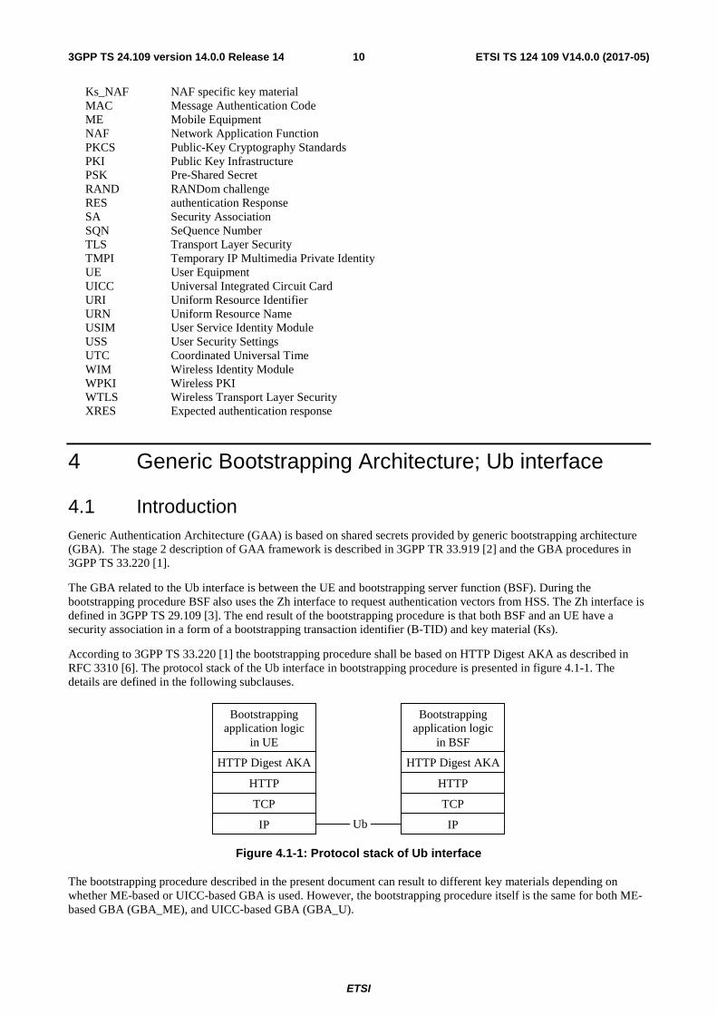
According to 3GPP TS 33.220 [1] the bootstrapping procedure shall be based on HTTP Digest AKA as described in RFC 3310 [6]. The protocol stack of the Ub interface in bootstrapping procedure is presented in figure 4.1-1. The details are defined in the following subclauses.
IP
TCP
HTTP
HTTP Digest AKA
Bootstrapping application logic
in UE
IP
TCP
HTTP
HTTP Digest AKA
Bootstrapping application logic
in BSF
Ub
Figure 4.1-1: Protocol stack of Ub interface
The bootstrapping procedure described in the present document can result to different key materials depending on whether ME-based or UICC-based GBA is used. However, the bootstrapping procedure itself is the same for both ME-based GBA (GBA_ME), and UICC-based GBA (GBA_U).

ETSI
ETSI TS 124 109 V14.0.0 (2017-05)113GPP TS 24.109 version 14.0.0 Release 14
The bootstrapping procedure can also be based on SIM, i.e., 2G GBA. The 2G GBA bootstrapping procedure is specified in Annex H.
The bootstrapping procedures can also be based on GBA_Digest. The GBA_Digest bootstrapping procedures is specified in annex I.
4.2 Bootstrapping procedure The UE shall initiate the bootstrapping procedure when:
a) the UE wants to interact with a NAF and bootstrapping is required;
b) a NAF has requested bootstrapping required indication as described in subclause 5.2.4 or bootstrapping renegotiation indication as described in subclause 5.2.5; or
c) the lifetime of the key has expired in the UE if one or more applications are using that key.
A UE and the BSF shall establish bootstrapped security association between them by running bootstrapping procedure. Bootstrapping security association consists of a bootstrapping transaction identifier (B-TID) and key material Ks. Bootstrapping session on the BSF also includes security related information about subscriber (e.g. user's private identity). Bootstrapping session is valid for a certain time period, and shall be deleted in the BSF when the session becomes invalid.
Bootstrapping procedure shall be based on HTTP Digest AKA as described in 3GPP TS 33.220 [1] and in RFC 3310 [6] with the modifications described below.
The BSF address is derived from the IMPI or IMSI according to 3GPP TS 23.003 [7].
A UE shall indicate to the BSF that it supports the use of TMPI as defined in 3GPP 33.220 [1] by including a "product" token in the "User-Agent" header field (cf. RFC 2616 [14]) that is set to a static string "3gpp-gba-tmpi" in HTTP requests sent to the BSF.
A BSF shall indicate to the UE that it supports the use of TMPI as defined in 3GPP 33.220 [1] by including a "product" token in the "Server" header field (cf. RFC 2616 [14]) that is set to a static string "3gpp-gba-tmpi" in HTTP responses sent to the UE.
In the bootstrapping procedure, Authorization, WWW-Authenticate, and Authentication-Info HTTP headers shall be used as described in RFC 3310 [6] with following exceptions:
a) the "realm" parameter shall contain the network name where the username is authenticated;
b) the quality of protection ("qop") parameter shall be "auth-int"; and
c) the "username" parameter shall contain user's private identity (IMPI).
NOTE: If the UE does not have an ISIM application with an IMPI, the IMPI will be constructed from IMSI, according to 3GPP TS 23.003 [7].
In addition to RFC 3310 [6], the following apply:
a) In the initial request from the UE to the BSF, the UE shall include Authorization header with following parameters:
- the username directive, set to
1) the value of the TMPI if one has been associated with the private user identity as described in 3GPP 33.220 [1]; or
2) the value of the private user identity;
- the realm directive, set to the BSF address derived from the IMPI or IMSI according to 3GPP TS 23.003 [7];
- the uri directive, set to either absoluteURL "http://<BSF address>/" or abs_path "/", and which one is used is specified in RFC 2617 [9];
ETSI
ETSI TS 124 109 V14.0.0 (2017-05)123GPP TS 24.109 version 14.0.0 Release 14
- the nonce directive, set to an empty value; and
- the response directive, set to an empty value;
b) In the challenge response from the BSF to the UE, the BSF shall include parameters to WWW-Authenticate header as specified in RFC 3310 [6] with following clarifications:
- the realm directive, set to the BSF address derived from the IMPI or IMSI according to 3GPP TS 23.003 [7];
c) In the message from the BSF to the UE, the BSF shall include bootstrapping transaction identifier (B-TID) and the key lifetime to an XML document in the HTTP response payload. The BSF may also include additional server specific data to the XML document. The XML schema definition of this XML document is given in Annex C.
d) When responding to a challenge from the BSF, the UE shall include an Authorization header containing a realm directive set to the value as received in the realm directive in the WWW-Authenticate header.
e) Authentication-Info header shall be included into the subsequent HTTP response after the BSF concluded that the UE has been authenticated. Authentication-Info header shall include the "rspauth" parameter.
After successful bootstrapping procedure the UE and the BSF shall contain the key material (Ks) and the B-TID. The key material shall be derived from AKA parameters as specified in 3GPP TS 33.220 [1]. In addition, BSF shall also contain a set of security specific attributes related to the UE.
An example flow of successful bootstrapping procedure can be found in clause A.3.
4.3 User authentication failure If the response returned by the UE is different than expected, the BSF may challenge the UE again with a new AKA challenge. After N consecutive incorrect responses from the UE, the BSF shall indicate a failure to the UE. The exact value of N is defined by local policy.
4.4 Network authentication failure In case the UE fails at authenticating the network, the UE shall abort the bootstrapping procedure.
4.5 Synchronization failure If the UE considers the sequence number in the challenge not to be in the correct, the UE shall send a synchronization failure indication back to the BSF as specified RFC 3310 [6].
An example flow can be found in clause A.4.
4A Generic Bootstrapping Achitecture Push; Upa
4A.1 Introduction Generic Authentication Architecture (GAA) is based on shared secrets provided by generic bootstrapping architecture (GBA). The stage 2 description of GAA framework is described in 3GPP TR 33.919 [2] and the GBA-Push procedures in 3GPP TS 33.223 [24].
The GBA-Push related to the Upa interface is between a NAF and UE. GBA-Push is a mechanism to bootstrap the security between a NAF and a UE, without forcing the UE to contact the BSF to initiate the bootstrapping. GBA-Push is closely related to and builds upon GBA as specified in 3GPP TS 33.220 [1]. GBA-Push is intended for both GBA_U and GBA_ME environments. The end result of the bootstrapping procedure is that the NAF and the UE have security associations, called NAF SAs, in the form of unique identifiers for uplink and downlink references and NAF-key material as defined in 3GPP TS 33.223 [24]. The unique identifiers take the following forms:

ETSI
ETSI TS 124 109 V14.0.0 (2017-05)133GPP TS 24.109 version 14.0.0 Release 14
RAND@'naf': Identifies NAF SA in the UE (used by NAF).
Value of P-TID: Identifies NAF SA in the NAF (used by UE).
The GBA-Push procedure shall be based on a disposable-Ks model as described in 3GPP TS 33.223 [24]. The protocol stack of the Upa interface in GBA-Push procedure is presented in figure 4A.1-1. The details are defined in the following subclauses.
Unspecified (e.g. SMS, MMS, SIP Message, etc)
GBA-Push application logic
in NAF
GBA-Push application logic
in UE
Upa
Unspecified (e.g. SMS, MMS, SIP Message, etc)
Figure 4A.1-1: Protocol stack of Upa interface
The bootstrapping procedure described in the present document can result in different key materials depending on whether ME-based or UICC-based GBA is used. However, the bootstrapping procedure over Upa interface itself is the same for both ME-based GBA (GBA_ME), and UICC-based GBA (GBA_U).
4A.2 Bootstrapping procedure The Push-NAF may initiate the bootstrapping procedure when:
a) the UE is registered for the intended service; and
b) the UE does not or can not perform a bootstrapping procedure directly with the BSF.
According to local policy, the Push-NAF may refresh the NAF SA before the expiry time of the NAF SA.
A Push-NAF and UE shall establish the NAF SA between them by running the bootstrapping procedure. The NAF SA consists of a NAF SA identifier, NAF-key material and. additional information as defined in 3GPP TS 33.223 [24]. The NAF SA is only valid for a certain time period, as determined by the NAF-key lifetime, and shall be deleted in the Push-NAF when the session expires.
The bootstrapping procedure shall be based on disposable Ks model and GBA-Push-Info (GPI) as defined in 3GPP TS 33.223 [24]. The Push-NAF pushes the GPI to the UE. The processing of GPI is defined in 3GPP TS 33.223 [24].
No specific transport method is mandated for transport of the GPI from the Push-NAF to the UE. However, when using specific transport methods, the transport address shall be determined as described in table 4A.2.1.
Table 4A.2.1: Transport addresses for Push message from Push-NAF to UE
Transport Method Transport Address SMS MSISDNMMS MSISDN SIP MESSAGE IMPU UDP IP-Address
Annex J specifies the protocol details when using WAP Push via SMS for the transport of the GPI from the Push-NAF to the UE.
After a successful bootstrapping procedure and processing of the GPI, the UE and the Push-NAF have established NAF SAs as described in 3GPP TS 33.223 [24].
An example flow of a successful bootstrapping procedure can be found in subclause A1.3.
ETSI
ETSI TS 124 109 V14.0.0 (2017-05)143GPP TS 24.109 version 14.0.0 Release 14
4A.3 User authentication failure User authentication is not applicable to GBA Push since all messages over the Upa interface are network initiated.
4A.4 Network authentication failure In case the UE fails to authenticate the network, the UE shall abort the bootstrapping procedure.
4A.5 Synchronization failure A disposable Ks model is used for GBA Push in order to avoid many synchronization problems. One situation when an out-of-synch problem will appear even with the adoption of the disposable Ks model is when the BSF may erase a valid Ks while the UE keeps it due to that the GBA Push message can not be validated at the UE. This will lead to an error situation if the UE tries to use a NAF specific key (Ks_(ext/int)_NAF) which is derived from such a Ks.
When this situation occurs, the Push-NAF will receive an error message from the BSF indicating that the Ks_(ext/int)_NAF (indicated by B-TID) is not available. The Push-NAF shall send this error message to the terminal. Upon receipt of the error message, indicating that the NAF specific key material is not available at the BSF, the UE shall perform a new bootstrap.
5 Network application function; Ua interface
5.1 Introduction The usage of bootstrapped security association i.e. B-TID and Ks_NAF (or Ks_ext_NAF or Ks_int_NAF) over Ua interface depends on the application protocol used between UE and NAF.
The Ua interface is used to supply the B-TID, generated during the bootstrapping procedure, to the network application function (NAF), and Zn interface is used by the NAF to retrieve the Ks_NAF or Ks_ext_NAF or Ks_int_NAF from BSF. The default is the use of Ks_(ext)_NAF, but the usage of Ks_int_NAF in Ua interface is possible. The Ua interface depends on type of NAF. The Zn interface is defined in 3GPP TS 29.109 [3]. This clause describes how B-TID and Ks_NAF or Ks_ext_NAF or Ks_int_NAF can be utilized, as specified in 3GPP TS 33.220 [1], and in the context of more specific Ua usage, as specified for deployment of HTTPS in 3GPP TS 33.222 [5], or for a PKI portal in 3GPP TS 33.221 [4]).
5.2 HTTP Digest authentication
5.2.1 General
The HTTP Digest authentication model as described in RFC 2617 [9] can be used with bootstrapped security association as the authentication and integrity protection method, if the application protocol used over Ua interface between UE and NAF is based on HTTP. The HTTP Digest authentication may be used for all protocols that have adopted the HTTP authentication framework to mutually authenticate the UE and the NAF, and also optionally integrity protect any payload being transferred between them.
The UE shall indicate to an application server (i.e. a NAF) that it supports 3GPP-bootstrapping based HTTP Digest authentication by including a "product" token to the "User-Agent" header (cf. RFC 2616 [14]) in outgoing HTTP requests. If the UE supports
a) AKA based authentication, then the "product" token is a static string "3gpp-gba" if the HTTP client application resides in the ME, or "3gpp-gba-uicc" if the HTTP client application resides in the UICC; or
b) GBA_Digest, then the "product" token is "3gpp-gba-digest".

ETSI
ETSI TS 124 109 V14.0.0 (2017-05)153GPP TS 24.109 version 14.0.0 Release 14
The UE may indicate multiple GBA modes by inserting multiple "product" tokens in the User-Agent header field. The User-Agent header field with GBA related "product" tokens shall be added to each outgoing HTTP request if the UE supports GBA-based authentication using HTTP Digest.
Upon receiving GBA related"product" tokens, the application server if it supports NAF functionality may decide to authenticate the UE using GBA-based shared secret by executing the authentication procedure. If multiple GBA modes have been indicated in the User-Agent header field, then the NAF selects one GBA mode and indicates the selected mode in responses to the UE in the "realm" parameter of the WWW-Authenticate header field. In the selection of the GBA mode by the UE, AKA-based modes shall take priority over GBA_Digest.
The protocol stack of the Ua interface when HTTP Digest authentication is used is presented in figure 5.2-1. The details are defined in the following subclauses.
Application logicin the UE
HTTP Digest
HTTP (Note 1)
TCP
IP
Application logicin the NAF
HTTP Digest
HTTP (Note 1)
TCP
IPUa
NOTE 1: HTTP is not the only protocol that can be used. Other protocols can also be used as long as the protocol has adopted the HTTP authentication framework. Figure 5.2-1: Protocol stack of Ua interface with HTTP Digest authentication
5.2.2 Authentication procedure
5.2.2.1 General
HTTP Digest authentication [9] shall be used with previously bootstrapped security association as follows:
1) the "username" parameter shall be the bootstrapping transaction identifier (B-TID);
2) the password used in the digest calculations shall be
a) in case of GBA_ME the NAF specific key material (Ks_NAF);
b) in case of GBA_U the NAF specific ME based key material (Ks_ext_NAF) or the NAF specific UICC-based key material (Ks_int_NAF);and
c) in case of GBA_Digest the NAF specific key material (Ks_NAF);
NOTE 1: The NAF specific key material (Ks_NAF or Ks_ext_NAF or Ks_int_NAF) is derived from the key material (Ks) using key derivation function as specified in 3GPP TS 33.220 [1].
The NAF specific key material (Ks_NAF or Ks_ext_NAF or Ks_int_NAF) is Base64 encoded as specified in RFC 3548 [10].
3 the "realm" parameter shall contain two parts delimited by "@" sign. The first part is the constant string "3GPP-bootstrapping" (in case of a ME-based application) , "3GPP-bootstrapping-uicc" (in case of a UICC-based application) or "3GPP-bootstrapping-digest " (in case of GBA_Digest), and the latter part shall be the FQDN of the NAF (e.g. "[email protected]" or "[email protected]" or "[email protected]").
In the case of GBA_U, the NAF shall indicate to the UE which NAF specific key was selected to be used by setting the first part of the realm to "3GPP-bootstrapping" (for the ME-based key i.e. Ks_ext_NAF), or to "3GPP-bootstrapping-uicc" (for the UICC-based key i.e. Ks_int_NAF).
Both the UE and the NAF shall verify upon receiving each of the HTTP responses and HTTP requests that the second part of the realm attribute is equal to the FQDN of the NAF.

ETSI
ETSI TS 124 109 V14.0.0 (2017-05)163GPP TS 24.109 version 14.0.0 Release 14
In the case of GBA_U, if the HTTPS client application resides in the ME, then the application shall use only the ME-based key i.e. Ks_ext_NAF (the UICC-based key Ks_int_NAF is not available in the ME). If the NAF indicates to the ME-based HTTPS client application that only UICC-based key shall be used, the application must terminate the communication with the NAF. If the HTTP client application resides in the UICC, then the application shall use only the UICC-based key. If the NAF indicates to the UICC-based application that only ME-based key shall be used, the application must terminate the communication with the NAF.
In the case of GBA_U, the operator may indicate the type of the key to be used in the Ua reference point in the NAF specific USS as specified in 3GPP TS 29.109 [3]. If the NAF has requested an application specific USS, and the indication is present in the USS, the NAF shall use the indicated key type. If the type of the negotiated key is different from the type indicated in the USS, the NAF shall terminate the communication with the UE.
An example flow of a successful HTTP Digest authentication procedure can be found in clause B.3.
5.2.3 Authentication failures
Authentication failures are handled as they are described in RFC 2617 [9].
5.2.4 Bootstrapping required indication
NAF shall indicate to the UE that bootstrapped security association is required by sending an HTTP response with code 401 "Unauthorized" and include the WWW-Authenticate header into the response. In particular, the "realm" attribute shall contain a prefix "3GPP-bootstrapping@" or "3GPP-bootstrapping-uicc@" or "3GPP-bootstrapping-digest", and this shall trigger UE to run bootstrapping procedure over Ub interface.
5.2.5 Bootstrapping renegotiation indication
The NAF shall indicate to the UE that the existing bootstrapped security association used in the last HTTP request sent by the UE has expired and that a new bootstrapped security association is required by sending an HTTP response described in subclause 5.2.3. When the UE receives the 401 "Unauthorized" HTTP response to the HTTP request that was protected using the existing bootstrapped security association, this shall trigger the UE to run bootstrapping procedure over Ub interface.
5.2.6 Integrity protection
Integrity protection may be provided by using HTTP Digest integrity protection, i.e. quality of protection (qop) parameter is set to "auth-int".
5.3 UE and NAF authentication using HTTPS
5.3.1 General
Prior to establishing HTTP, the UE and the NAF may perform authentication. Three different authentication mechanisms may be used for UE and NAF authentication:
a) Shared key-based UE authentication (HTTP Digest) with certificate-based NAF authentication (TLS);
b) Shared key-based mutual authentication between UE and NAF (PSK TLS), and;
c) Certificate based mutual authentication between UE and AS;
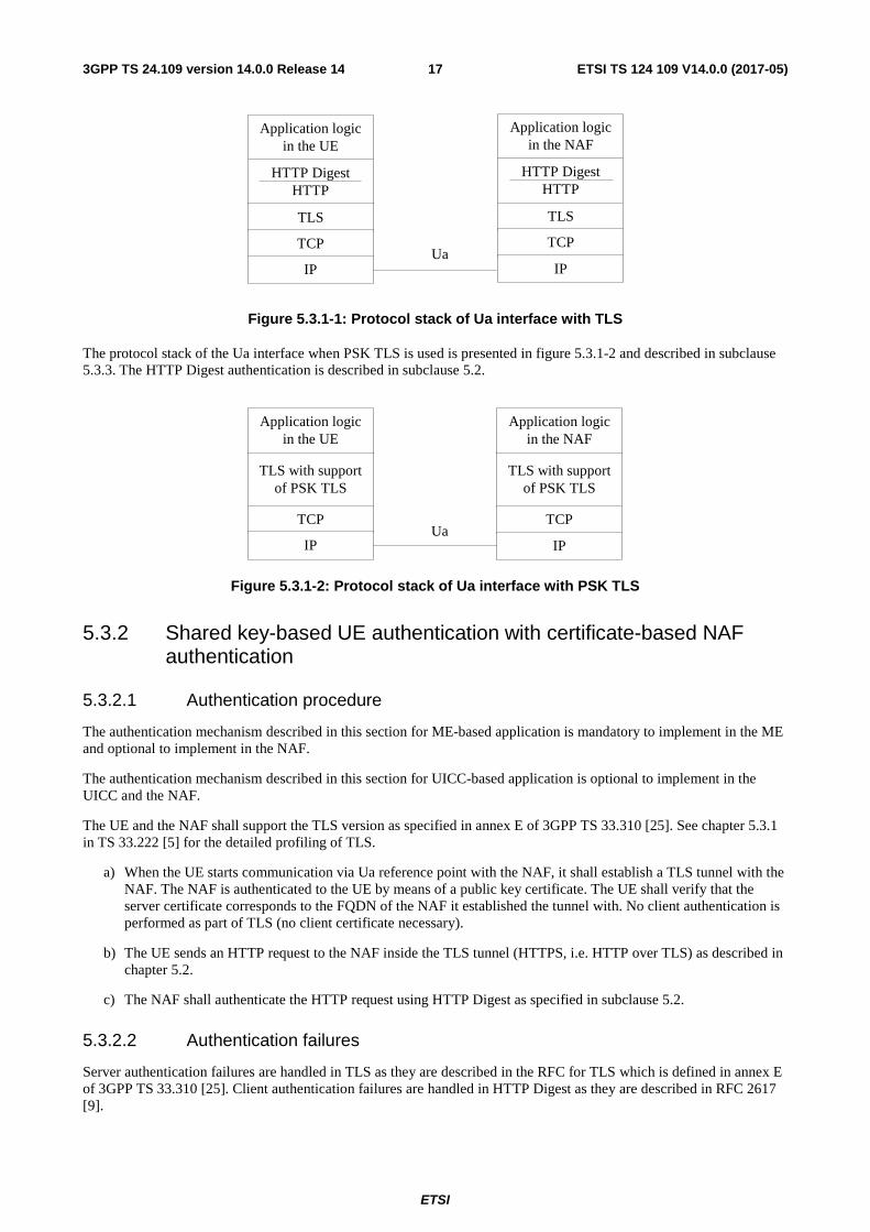
The protocol stack of the Ua interface when TLS is used is presented in figure 5.3.1-1. and described in subclause 5.3.2. The HTTP Digest authentication is described in subclause 5.2.
ETSI
ETSI TS 124 109 V14.0.0 (2017-05)173GPP TS 24.109 version 14.0.0 Release 14
HTTP DigestHTTP
TLS
TCP
IP
HTTP DigestHTTP
TLS
TCP
IPUa
Application logicin the UE
Application logicin the NAF
Figure 5.3.1-1: Protocol stack of Ua interface with TLS
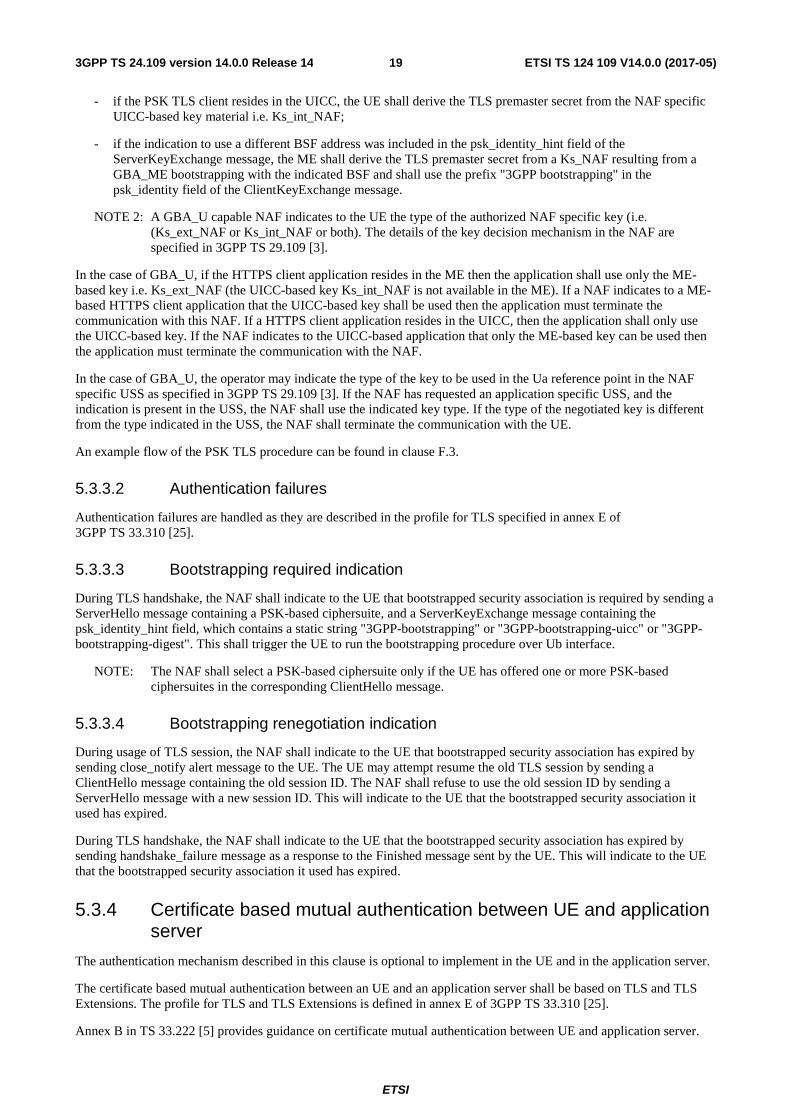
The protocol stack of the Ua interface when PSK TLS is used is presented in figure 5.3.1-2 and described in subclause 5.3.3. The HTTP Digest authentication is described in subclause 5.2.
TLS with supportof PSK TLS
TCP
IP
TLS with supportof PSK TLS
TCP
IPUa
Application logicin the UE
Application logicin the NAF
Figure 5.3.1-2: Protocol stack of Ua interface with PSK TLS
5.3.2 Shared key-based UE authentication with certificate-based NAF authentication
5.3.2.1 Authentication procedure
The authentication mechanism described in this section for ME-based application is mandatory to implement in the ME and optional to implement in the NAF.
The authentication mechanism described in this section for UICC-based application is optional to implement in the UICC and the NAF.
The UE and the NAF shall support the TLS version as specified in annex E of 3GPP TS 33.310 [25]. See chapter 5.3.1 in TS 33.222 [5] for the detailed profiling of TLS.
a) When the UE starts communication via Ua reference point with the NAF, it shall establish a TLS tunnel with the NAF. The NAF is authenticated to the UE by means of a public key certificate. The UE shall verify that the server certificate corresponds to the FQDN of the NAF it established the tunnel with. No client authentication is performed as part of TLS (no client certificate necessary).
b) The UE sends an HTTP request to the NAF inside the TLS tunnel (HTTPS, i.e. HTTP over TLS) as described in chapter 5.2.
c) The NAF shall authenticate the HTTP request using HTTP Digest as specified in subclause 5.2.
5.3.2.2 Authentication failures
Server authentication failures are handled in TLS as they are described in the RFC for TLS which is defined in annex E of 3GPP TS 33.310 [25]. Client authentication failures are handled in HTTP Digest as they are described in RFC 2617 [9].

ETSI
ETSI TS 124 109 V14.0.0 (2017-05)183GPP TS 24.109 version 14.0.0 Release 14
5.3.2.3 Bootstrapping required indication
Bootstrapping required indication is done on HTTP Digest and therefore described in subclause 5.2.4.
5.3.2.4 Bootstrapping renegotiation indication
Bootstrapping renegotiation indication is done on HTTP Digest and therefore described in subclause 5.2.5.
5.3.3 Shared key-based mutual authentication between UE and NAF
5.3.3.1 Authentication procedure
The authentication mechanism described in this section for ME-based application is optional to implement in the ME and the NAF.
The authentication mechanism described in this section for UICC-based application is optional to implement in the UICC and the NAF.
The Pre-Shared Key Ciphersuites for TLS (PSK TLS) may be used with bootstrapped security association as the authentication, confidentiality, and integrity protection method. The profile for TLS and TLS Extensions to be used together with PSK TLS is defined in annex E of 3GPP TS 33.310 [25].
The PSK TLS handshake shall be used with bootstrapped security association as follows:
- the ClientHello message shall contain one or more PSK-based ciphersuites;
- the ClientHello message shall contain the server_name TLS extension and it shall contain the hostname of the NAF;
- the ServerHello message shall contain a PSK-based ciphersuite selected by the NAF;
- the ServerKeyExchange shall be sent by the server and it shall contain the psk_identity_hint field and it shall contain the static string "3GPP-bootstrapping" or "3GPP-bootstrapping-uicc" or "3GPP-bootstrapping-digest". If several authentication methods are supported then the ServerKeyExchange message shall include the PSK-identity hints for all allowed authentication methods, separated by semi-colon ";" (e.g., "3GPP-bootstrapping;3GPP-bootstrapping-uicc").
In the case of GBA_U, the NAF shall indicate to the UE which NAF specific key can be used by setting the psk_identity_hint to "3GPP-bootstrapping" (for the ME-based key i.e. Ks_ext_NAF), or to "3GPP-bootstrapping-uicc" (for the UICC-based key i.e. Ks_int_NAF). If the NAF allows both types of keys to be used then the psk_identity_hint field shall contain both hints separated by semi-colon ";".
In addition, the NAF may include an indication to use a BSF address different from the one specified in 3GPP TS 23.003 [7] in the psk_identity_hint field of the ServerKeyExchange message. The indication to use the different BSF address shall contain a prefix "3GPP bootstrapping-BSF-address", a separator character ":" and the FQDN of the BSF. The NAF may only include this indication for an application specified to support this functionality (e.g. Proximity-based Services, see 3GPP TS 33.303 [29]) and if it is included then the static strings "3GPP bootstrapping" shall be included.
The psk_identity_hint field may contain a list of psk_identity_hints and are separated by a semi-colon character (";") (see NOTE 1);
NOTE 1: Other psk identity name spaces than "3GPP-bootstrapping" or "3GPP-bootstrapping-uicc" can be supported, however, they are out of the scope of this specification.
- the ClientKeyExchange shall contain the psk_identity field and it shall contain a prefix "3GPP-bootstrapping" or "3GPP-bootstrapping-uicc" or "3GPP-bootstrapping-digest" indicating the selected psk identity name space, a separator character ";" and the B-TID. In the selection of the GBA mode by the UE, AKA-based modes shall take priority over GBA_Digest.;
- if the PSK TLS client resides in the ME, the UE shall derive the TLS premaster secret from the NAF specific key material i.e. Ks_NAF in the case of GBA_ME. For GBA_U the UE shall derive the TLS premaster secret from the ME-based key material i.e. Ks_ext_NAF;
ETSI
ETSI TS 124 109 V14.0.0 (2017-05)193GPP TS 24.109 version 14.0.0 Release 14
- if the PSK TLS client resides in the UICC, the UE shall derive the TLS premaster secret from the NAF specific UICC-based key material i.e. Ks_int_NAF;
- if the indication to use a different BSF address was included in the psk_identity_hint field of the ServerKeyExchange message, the ME shall derive the TLS premaster secret from a Ks_NAF resulting from a GBA_ME bootstrapping with the indicated BSF and shall use the prefix "3GPP bootstrapping" in the psk_identity field of the ClientKeyExchange message.
NOTE 2: A GBA_U capable NAF indicates to the UE the type of the authorized NAF specific key (i.e. (Ks_ext_NAF or Ks_int_NAF or both). The details of the key decision mechanism in the NAF are specified in 3GPP TS 29.109 [3].
In the case of GBA_U, if the HTTPS client application resides in the ME then the application shall use only the ME-based key i.e. Ks_ext_NAF (the UICC-based key Ks_int_NAF is not available in the ME). If a NAF indicates to a ME-based HTTPS client application that the UICC-based key shall be used then the application must terminate the communication with this NAF. If a HTTPS client application resides in the UICC, then the application shall only use the UICC-based key. If the NAF indicates to the UICC-based application that only the ME-based key can be used then the application must terminate the communication with the NAF.
In the case of GBA_U, the operator may indicate the type of the key to be used in the Ua reference point in the NAF specific USS as specified in 3GPP TS 29.109 [3]. If the NAF has requested an application specific USS, and the indication is present in the USS, the NAF shall use the indicated key type. If the type of the negotiated key is different from the type indicated in the USS, the NAF shall terminate the communication with the UE.
An example flow of the PSK TLS procedure can be found in clause F.3.
5.3.3.2 Authentication failures
Authentication failures are handled as they are described in the profile for TLS specified in annex E of 3GPP TS 33.310 [25].
5.3.3.3 Bootstrapping required indication
During TLS handshake, the NAF shall indicate to the UE that bootstrapped security association is required by sending a ServerHello message containing a PSK-based ciphersuite, and a ServerKeyExchange message containing the psk_identity_hint field, which contains a static string "3GPP-bootstrapping" or "3GPP-bootstrapping-uicc" or "3GPP-bootstrapping-digest". This shall trigger the UE to run the bootstrapping procedure over Ub interface.
NOTE: The NAF shall select a PSK-based ciphersuite only if the UE has offered one or more PSK-based ciphersuites in the corresponding ClientHello message.
5.3.3.4 Bootstrapping renegotiation indication
During usage of TLS session, the NAF shall indicate to the UE that bootstrapped security association has expired by sending close_notify alert message to the UE. The UE may attempt resume the old TLS session by sending a ClientHello message containing the old session ID. The NAF shall refuse to use the old session ID by sending a ServerHello message with a new session ID. This will indicate to the UE that the bootstrapped security association it used has expired.
During TLS handshake, the NAF shall indicate to the UE that the bootstrapped security association has expired by sending handshake_failure message as a response to the Finished message sent by the UE. This will indicate to the UE that the bootstrapped security association it used has expired.
5.3.4 Certificate based mutual authentication between UE and application server
The authentication mechanism described in this clause is optional to implement in the UE and in the application server.
The certificate based mutual authentication between an UE and an application server shall be based on TLS and TLS Extensions. The profile for TLS and TLS Extensions is defined in annex E of 3GPP TS 33.310 [25].
Annex B in TS 33.222 [5] provides guidance on certificate mutual authentication between UE and application server.
ETSI
ETSI TS 124 109 V14.0.0 (2017-05)203GPP TS 24.109 version 14.0.0 Release 14
5.3.5 Integrity protection
Integrity protection is provided by using authenticated TLS tunnel as described in RFC 2818 [12].
6 PKI portal, Ua interface
6.1 Introduction 3GPP TS 33.221 [4] specifies the enrolment of subscriber certificates and the delivery of CA certificates to the UE. The TS specifies that the authentication of these procedures be based on bootstrapping procedure and more generally on the HTTP Digest authentication as described in subclause 5.2 of the present document.
6.2 Subscriber certificate enrolment The subscriber certificate enrolment procedure contains the following requests:
- an enrolment request in the form of PKCS#10 [16];
- an optional request for WIM specific authentication code for key generation [19]; and
- an optional request for WIM specific authentication code for proof of key origin [19].
Respectively, the subscriber certificate enrolment procedure contains the following responses:
- a subscriber certificate; and
- a WIM specific authentication code [19].
NOTE: The on board key generation and the generation of the proof of key origin requires a WIM specific authentication code. Whether it is, is decided by the issuer of the WIM card.
6.2.1 Enrolment procedure
The UE shall generate a PKCS#10 certification request [16] according to 3GPP TS 33.221 [4]. The UE shall send the PKCS#10 certification request to the PKI portal in the HTTP payload in a HTTP POST request. The Request-URI shall indicate the desired response type. Upon successful enrolment, PKI portal shall return the enrolled subscriber certificate in the desired format.
The UE populates the HTTP POST request as follows:
- the HTTP version shall be 1.1 which is specified in RFC 2616 [14];
- the base of the Request-URI is extracted from the full PKI portal URI (e.g. if the full PKI portal URI is "http://pki-portal.operator.com/enrol" then the Request-URI shall be "/enrol".
NOTE 1: In case a proxy is used between the UE and the PKI portal, then the full Request-URI will be used in the HTTP Post request.
- the Request-URI shall contain an URI parameter "response" that shall be set to "single", "pointer", or "chain" depending on the UE's desired response type (e.g. Request-URI may take the form of "/enrol?response=single" for certificate delivery);
NOTE 2: The PKI portal might ignore the UE's desired response type, and the UE should be capable of receiving the issued subscriber certificate in any of the response types.
- the UE may add additional URI parameters to the Request-URI;
NOTE 3: The PKI portal might ignore the additional URI parameters.
- the HTTP header Content-Type shall be "application/x-pkcs10";

ETSI
ETSI TS 124 109 V14.0.0 (2017-05)213GPP TS 24.109 version 14.0.0 Release 14
- the HTTP header Content-Length shall be the length of the Base64 encoded PKCS#10 certification request in Octets; and
- the HTTP payload shall contain the Base64 encoded PKCS#10 certification request and optionally surrounded by "----- BEGIN CERTIFICATE REQUEST -----" and "----- END CERTIFICATE REQUEST -----" tags;
- the UE may add additional HTTP headers to the HTTP POST request.
The UE sends the HTTP POST request to the PKI portal. The PKI portal checks that the HTTP request is valid, and extracts the Base64 encoded PKCS#10 certification request for further processing. The PKI portal shall verify that the subscriber is authorized to receive the particular type of certificate by checking subscriber's user security settings received from the BSF as specified 3GPP TS 33.220 [1].
Upon successful subscriber certificate creation procedure, the PKI portal shall return the subscriber certificate to the UE in the UE's desired format or in the PKI portal's desired format.
The response format type shall be one of the following:
- the subscriber certificate itself (i.e. desired response type was "single");
- a pointer to the subscriber certificate (i.e. desired response type was "pointer"); or
- a certificate chain that contains full certification chain from subscriber certificate to the root certificate (i.e. desired response type was "chain").
If response format type is "single", the PKI portal shall populate HTTP response as follows:
- the HTTP status code shall be 200;
- the HTTP header Content-Type shall be "application/x-x509-user-cert";
- the HTTP header Content-Length shall be the length of the HTTP payload in octets;
- the HTTP payload shall contain the Base64 encoded subscriber certificate and optionally surrounded by "----- BEGIN CERTIFICATE -----" and "----- END CERTIFICATE -----" tags;
- the PKI portal may add additional HTTP headers to the HTTP response.
If response format type is "pointer", the PKI portal shall populate HTTP response as follows:
- the HTTP status code shall be 200;
- the HTTP header Content-Type shall be "application/vnd.wap.cert-response";
- the HTTP header Content-Length shall be the length of the HTTP payload in octets;
- the HTTP payload shall contain the Base64 encoded CertResponse structure and optionally surrounded by "----- BEGIN CERTIFICATE RESPONSE -----" and "----- END CERTIFICATE RESPONSE -----" tags;
- the PKI portal may add additional HTTP headers to the HTTP response.
If response format type is "chain", the PKI portal shall populate HTTP response as follows:
- the HTTP status code shall be 200;
- the HTTP header Content-Type shall be "application/pkix-pkipath";
- the HTTP header Content-Length shall be the length of the HTTP payload in octets;
- the HTTP payload shall contain the Base64 encoded PkiPath structure;
- the PKI portal may add additional HTTP headers to the HTTP response.
The PKI portal shall send the HTTP response to the UE. The UE shall check that the HTTP response is valid, and extract the Base64 encoded subscriber certificate, pointer to the subscriber certificate, or certificate chain for further processing.
An example flow of a successful subscriber certificate enrolment procedure can be found in clause E.3.
ETSI
ETSI TS 124 109 V14.0.0 (2017-05)223GPP TS 24.109 version 14.0.0 Release 14
6.2.2 WIM specific authentication code for key generation
The UE may be equipped with a WIM which may require an authentication code from WIM provider in order to generate a key onboard WIM as specified in OMA ECMAScript [19] and OMA WPKI [20] specifications. In this case, the UE shall request the authentication code from PKI portal using a HTTP GET request. If the PKI portal can acquire authentication code, it is returned to the UE in the corresponding HTTP response.
The UE populates the HTTP GET request as follows:
- the HTTP version shall be 1.1 which is specified in RFC 2616 [14];
- the base of the Request-URI is extracted from the full PKI portal URI and appended with "/wim-auth-code" (e.g. if the full PKI portal URI is "http://pki-portal.operator.com/enrol" then the Request-URI shall be "/enrol/wim-auth-code");
- the Request-URI shall contain an URI parameter "request" that shall be set to the return value received from the WIM;
NOTE 1: If an authentication code is required, the WIM will return "error:AuthReq:cardSerialNumber:Challenge". The cardSerialNumber and the Challenge are in a hexadecimal format as specified in OMA ECMAScript specification [19].
- the UE may add additional URI parameters to the Request-URI;
- the UE may add additional HTTP headers to the HTTP GET request.
The UE sends the HTTP GET request to the PKI portal. The PKI portal acknowledges that this is an authentication code because the Request-URI contains the "/wim-auth-code" and the URI parameter "request". The PKI portal extracts the authentication code derivation parameters from the URI parameter "request", and derives the authentication code.
NOTE 2: The actual derivation of the authentication code is outside the scope.
Upon successful authentication code derivation, the PKI portal shall return the authentication code to the UE in a HTTP response:
- the HTTP status code shall be 200;
- the HTTP header Content-Type shall be "text/plain";
- the HTTP header Content-Length shall be the length of the HTTP payload in octets;
- the HTTP payload shall contain the authentication code in a hexadecimal format;
- the PKI portal may add additional HTTP headers to the HTTP response.
Upon receiving the authentication code from the PKI portal, the UE shall use it to authenticate the procedure of generating the key onboard the WIM.
6.2.3 WIM specific authentication code for proof of key origin
The UE may be equipped with a WIM which may require an authentication code from WIM provider in order to generate a proof of key origin onboard WIM as specified in OMA ECMAScript [19] and OMA WPKI [20] specifications. In this case, the UE shall request the authentication code from PKI portal using a HTTP GET request. If the PKI portal can acquire authentication code, it is returned to the UE in the corresponding HTTP response.
The procedure to obtain the authentication code for the generation of proof of key origin onboard WIM is the same as for the key generation, and is described in subclause D.2.1.
Upon receiving the authentication code from the PKI portal, the UE shall use it to authenticate the procedure generating the proof of key origin onboard the WIM.

ETSI
ETSI TS 124 109 V14.0.0 (2017-05)233GPP TS 24.109 version 14.0.0 Release 14
6.2.4 Error situations
Subscriber certificate enrolment may not be successful for multiple reasons. The error cases are indicated by using 4xx and 5xx HTTP Status Codes as defined in RFC 2616 [14]. The 4xx status code indicates that the UE seems to have erred, and the 5xx status code indicates that the PKI portal is aware that it has erred. Possible error situations during subscriber certificate enrolment and their mappings to HTTP Status Codes are described in table 6.2.4-1.
NOTE: On the table 6.2.4-1, the "Description" column describes the error situation in PKI portal. The "PKI portal error" column describes the typical reason for the error.
An example flow of a failure in subscriber certificate enrolment procedure can be found in clause E.4.
Table 6.2.4-1: HTTP Status Codes used for enrolment error
HTTP Status Code
HTTP Error UE should repeat the
request
Description PKI portal error
400 Bad Request No Request could not be understood
PKCS#10 request was missing, or malformed
401 Unauthorized Yes Request requires authentication (cf. subclause 5.2)
Authentication pending, cf. subclause 5.2
402 Payment Required
No Reserved for future use -
403 Forbidden No PKI portal understood the request, but is refusing to fulfil it
PKCS#10 request was valid, but subscriber is not allowed to enrol this particular type of certificates or PKCS#10 request contained unacceptable parameters
404 Not Found No PKI portal has not found anything matching the Request-URI
The Request-URI was malformed and PKI portal cannot fulfil the enrolment request
405 to 406 * No Not used by PKI portal - 407 Proxy
Authentication Required
Yes PKI portal uses Authentication Proxy and UE shall authenticate itself with the proxy
Authentication Proxy authentication pending, cf. subclause 5.2
408 to 417 * No PKI portal should not use these status codes
-
500 Internal Server Error
No PKI portal encountered an unexpected error
PKI portal is mis-configured
501 Not Implemented
No PKI portal does not support the required functionality
The server does not contain PKI portal service
502 Bad Gateway No Gateway/Proxy received an invalid response from PKI portal
PKI portal is behind a gateway/proxy and sent an invalid response to the gateway/proxy
503 Service Unavailable
Yes PKI portal service is currently unavailable
PKI portal is temporarily unavailable, UE may repeat the request after delay indicated by "Retry-After" header
504 Gateway Timeout
No Gateway/Proxy did not receive a timely response from the upstream server
PKI portal is behind a gateway/proxy and did not send a response to the gateway/proxy in time, or was not reachable by the gateway/proxy
505 HTTP Version Not Supported
No PKI portal does not support the HTTP protocol version that was used in the request line
UE should use HTTP/1.1 version with PKI portal
6.3 CA certificate delivery The root certificate delivery procedure contains the following request:
- a CA certificate delivery request;

ETSI
ETSI TS 124 109 V14.0.0 (2017-05)243GPP TS 24.109 version 14.0.0 Release 14
and the corresponding response:
- the CA certificate.
6.3.1 CA certificate delivery procedure
The UE shall populate the HTTP GET request as follows:
- the HTTP version shall be 1.1 which is specified in RFC 2616 [14];
- the base of the Request-URI is extracted from the full PKI portal URI (e.g. if the full PKI portal URI is "http://pki-portal.operator.com/getcertificate" then the Request-URI shall be "/getcertificate".
NOTE 1: In case a proxy is used between the UE and the PKI portal, then the full Request-URI will be used in the HTTP Post request.
- the Request-URI shall contain an URI parameter "in" that shall be the Base64 encoding of the DER encoded Issuer field of the X.509 certificate;
- the Request-URI may contain an URI parameter "ki" that shall be the Base64 encoding of the DER encoded the Key Identifier of the X.509 certificate;
NOTE 2: Key Identifier of the CA certificate can be obtained from the Authority Key Identifier extension of the subscriber certificate.
- the UE may add additional URI parameters to the Request-URI;
- the UE may add additional HTTP headers to the HTTP GET request.
The UE sends the HTTP GET request to the PKI portal. The PKI portal checks that the HTTP request is valid, and extracts the "in" parameter and optionally "ki" parameter from the Request-URI. If the PKI portal can verify that the Issuer field parameter is valid, and that the UE may set the CA certificate as a root certificate (i.e. trusted CA certificate), it will then send the CA certificate back to the UE in the corresponding HTTP response.
The PKI portal shall populate the HTTP response as follows:
- the HTTP status code shall be 200;
- the HTTP header Content-Type shall be "application/x-x509-ca-cert";
- the HTTP header Content-Length shall be the length of the HTTP payload in octets;
- the HTTP payload shall contain the Base64 encoded CA certificate structure and optionally surrounded by "----- BEGIN CERTIFICATE -----" and "----- END CERTIFICATE -----" tags;
- the PKI portal may add additional HTTP headers to the HTTP response.
The PKI portal shall send the HTTP response to the UE. The UE shall check that the HTTP response is valid, and extract the Base64 encoded CA certificate for further processing. UE shall validate and match the received CA certificate against the parameters supplied in the corresponding request.
An example flow of CA certificate procedure can be found in clause E.5.
6.3.2 Error situations
CA certificate delivery may not be successful for multiple reasons. The error cases are indicates by using 4xx and 5xx HTTP Status Codes as defined in RFC 2616 [14]. The 4xx status code indicates that the UE seems to have erred, and the 5xx status codes indicate that the PKI portal is aware that it has erred. Possible error situations during CA certificate delivery and their mappings to HTTP Status Codes are described in table 6.3.2-1.
NOTE: On the table 6.3.2-1, the "Description" column describes the error situation in PKI portal. The "PKI portal error" column describes the typical reason for the error.
An example flow of a failure in CA certificate delivery procedure can be found in clause E.6.

ETSI
ETSI TS 124 109 V14.0.0 (2017-05)253GPP TS 24.109 version 14.0.0 Release 14
Table 6.3.2-1: HTTP Status Codes for CA certificate delivery error
HTTP Status Code
HTTP Error UE should repeat the
request
Description PKI portal error
400 Bad Request No Request could not be understood
Request could not be understood
401 Unauthorized Yes Request requires authentication (cf. subclause 5.2)
Authentication pending, cf. subclause 5.2
402 Payment Required
No Reserved for future use -
403 Forbidden No PKI portal understood the request, but is refusing to fulfil it
CA certificate delivery request was understood but PKI portal refuses to deliver the CA certificate
404 Not Found No PKI portal has not found anything matching the Request-URI
PKI portal does not have the requested CA certificate
405 to 406 * No Not used by PKI portal - 407 Proxy
Authentication Required
Yes PKI portal uses Authentication Proxy and UE shall authenticate itself with the proxy
Authentication Proxy authentication pending, cf. subclause 5.2
408 to 417 * No PKI portal should not use these status codes
-
500 Internal Server Error
No PKI portal encountered an unexpected error
PKI portal is mis-configured
501 Not Implemented
No PKI portal does not support the required functionality
The server does not contain PKI portal service
502 Bad Gateway No Gateway/Proxy received an invalid response from PKI portal
PKI portal is behind a gateway/proxy and sent an invalid response to the gateway/proxy
503 Service Unavailable
Yes PKI portal service is currently unavailable
PKI portal is temporarily unavailable, UE may repeat the request after delay indicated by "Retry-After" header
504 Gateway Timeout
No Gateway/Proxy did not receive a timely response from the upstream server
PKI portal is behind a gateway/proxy and did not send a response to the gateway/proxy in time, or was not reachable by the gateway/proxy
505 HTTP Version Not Supported
No PKI portal does not support the HTTP protocol version that was used in the request line.
UE should use HTTP/1.1 version with PKI portal
7 Authentication Proxy
7.1 Introduction The use of authentication proxy (AP) is specified in 3GPP TS 33.222 [5]. The AP in GAA is used to separate the GAA specific authentication procedure and the Application Server (AS) specific application logic to different logical entities. The AP is configured as a HTTP reverse proxy, i.e. the FQDN of the AS is configured to the AP such a way that the IP traffic intended to the AS is directed to the AP by the network. The AP performs the GAA authentication of the UE. After the GAA authentication procedure has been successfully completed, the AP assumes the typical role of a reverse proxy, i.e. the AP forwards HTTP requests originating from the UE to the correct AS, and returns the corresponding HTTP responses from the AS to the originating UE.
ETSI
ETSI TS 124 109 V14.0.0 (2017-05)263GPP TS 24.109 version 14.0.0 Release 14
7.2 Authentication The authentication of the UE shall be based on GAA as specified in clause 5.
The AP shall remove the "Authorization" header from the HTTP requests that are forwarded from the UE to the AS. The AP shall add the "Authentication-Info" header to the HTTP responses that are forwarded to the UE from the AS.
The UE may indicate the user identity intended to be used with the AS by adding a HTTP header to the outgoing HTTP requests. The HTTP header name shall be "X-3GPP-Intended-Identity" and it shall contain the user identity surrounded by quotation marks ("). If the HTTP header has been added, the AP may verify that the user identity belongs to the subscriber. In case the AP supports this check of the user identity then it shall be performed dependant on the subscriber’s application specific or AP specific user security settings.
7.3 Authorization The AP shall be able to decide whether particular subscriber, i.e. the UE, is authorized to access a particular AS. The granularity of the authorization procedures is specified in 3GPP TS 33.222 [5].
The AP may indicate an asserted identity or a list of identities to the AS by adding a HTTP header to the HTTP requests coming from the UE and forwarded to the AS. The HTTP header name shall be "X-3GPP-Asserted-Identity" and it shall contain a list of identities separated by comma (,) and each identity is surrounded by quotation marks ("). Whether the AP supports this handling of an asserted identity or a list of identities then it shall depend on local policy in the AP. In addition the subscriber’s application specific or AP specific user security settings may be considered.
The AP may indicate an authorization flag or a list of authorization flags from the application specific user security settings (USS) to the AS by adding a HTTP header to the HTTP requests coming from the UE and forwarded to the AS. The HTTP header name shall be "X-3GPP-Authorization-Flags" and it shall contain a list of authorization flags separated by comma (,) and each authorization flag is surrounded by quotation marks ("). In case the AP supports this handling of authorization flags from USS then it shall depend on local policy in the AP.

ETSI
ETSI TS 124 109 V14.0.0 (2017-05)273GPP TS 24.109 version 14.0.0 Release 14
Annex A (informative): Signalling flows of bootstrapping procedure
A.1 Scope of signalling flows This annex gives examples of signalling flows for bootstrapping procedure.
A.2 Introduction
A.2.1 General Bootstrapping procedure is executed in order to establish bootstrapped security association, i.e. bootstrapping session between an UE and the BSF.
The bootstrapping session is used between a UE and a NAF. An example usage of it is described in annex B.
A.2.2 Key required to interpret signalling flows 3GPP TS 24.228 [13], subclause 4.1.1, specifies the key required to interpret the contents of the SIP methods. This key is used with HTTP based messages (cf. RFC 2616 [14]) as well since SIP and HTTP messages resemble each other in structure. The following key rules are used in addition to those specified in 3GPP TS 24.228 [13]:
a) The HTTP based messaging is always initiated by the client:
- HTTP request is generated by the client (i.e. UE);
- HTTP response is generated by the server as a response to the HTTP request;
- HTTP proxies may be between the client and the server.
b) There is only one single HTTP response to the HTTP request.
c) In order to differentiate between HTTP messages and other protocol messages, the HTTP messages are marked with simple arrow line, and all non-HTTP messages with block arrows.
d) The flows show the signalling exchanges between the following functional entities in addition to those specified in 3GPP TS 24.228 [13]:
- Bootstrapping Server Function (BSF);
- Network Application Function (NAF);
- PKI portal (PKI portal).
e) The "(B-TID)" sequence of characters is used to indicate that the bootstrapping transaction identifier (B-TID) needs to be filled in.
A.3 Signalling flows demonstrating a successful bootstrapping procedure
The overall bootstrapping procedure in successful case is presented in figure A.3-1. The bootstrapping Zh interface performs the retrieval of an authentication vector by BSF from the HSS. The procedure corresponds to the step 2 in figure A.3-1.

ETSI
ETSI TS 124 109 V14.0.0 (2017-05)283GPP TS 24.109 version 14.0.0 Release 14
This clause specifies in detail the format of the bootstrapping procedure that is further utilized by various applications. It contains the AKA authentication procedure with BSF, and later the bootstrapping key material generation procedure.
UE BSF HSS
5. Generation of response and session keys
7. Authentication and generation of bootstrapping key material
9. Generation of bootstrapping key material
1. initial GET
4. 401 Unauthorized
6. GET
8. 200 OK
2. Zh interface
3. Authentication vector selection
Figure A.3-1: Bootstrapping signalling
1. Initial GET request (UE to BSF) - see example in table A.3-1
The purpose of this message is to initiate bootstrapping procedure between the UE and BSF. The UE sends an HTTP request containing the private user identity towards its home BSF.
Table A.3-1: Initial GET request (UE to BSF)
GET / HTTP/1.1 Host: bsf.home1.net:80 User-Agent: Bootstrapping Client Agent; Release-6; 3gpp-gba-tmpi Date: Thu, 08 Jan 2004 10:13:17 GMT Accept: */* Authorization: Digest username="[email protected]", realm="bsf.home1.net", nonce="", uri="/", response=""
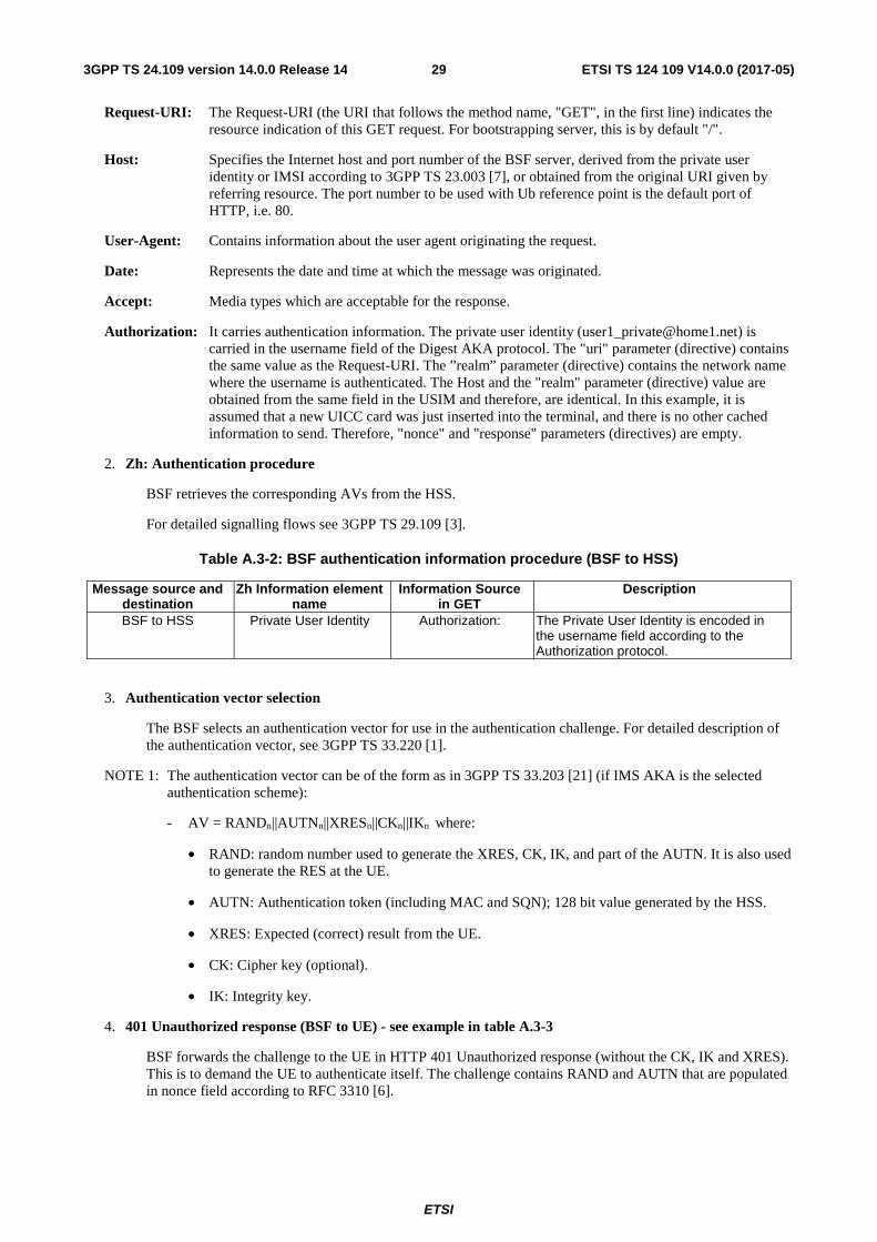
ETSI
ETSI TS 124 109 V14.0.0 (2017-05)293GPP TS 24.109 version 14.0.0 Release 14
Request-URI: The Request-URI (the URI that follows the method name, "GET", in the first line) indicates the resource indication of this GET request. For bootstrapping server, this is by default "/".
Host: Specifies the Internet host and port number of the BSF server, derived from the private user identity or IMSI according to 3GPP TS 23.003 [7], or obtained from the original URI given by referring resource. The port number to be used with Ub reference point is the default port of HTTP, i.e. 80.
User-Agent: Contains information about the user agent originating the request.
Date: Represents the date and time at which the message was originated.
Accept: Media types which are acceptable for the response.
Authorization: It carries authentication information. The private user identity ([email protected]) is carried in the username field of the Digest AKA protocol. The "uri" parameter (directive) contains the same value as the Request-URI. The ”realm” parameter (directive) contains the network name where the username is authenticated. The Host and the "realm" parameter (directive) value are obtained from the same field in the USIM and therefore, are identical. In this example, it is assumed that a new UICC card was just inserted into the terminal, and there is no other cached information to send. Therefore, "nonce" and "response" parameters (directives) are empty.
2. Zh: Authentication procedure
BSF retrieves the corresponding AVs from the HSS.
For detailed signalling flows see 3GPP TS 29.109 [3].
Table A.3-2: BSF authentication information procedure (BSF to HSS)
Message source and destination
Zh Information element name
Information Source in GET
Description
BSF to HSS Private User Identity Authorization: The Private User Identity is encoded in the username field according to the Authorization protocol.
3. Authentication vector selection
The BSF selects an authentication vector for use in the authentication challenge. For detailed description of the authentication vector, see 3GPP TS 33.220 [1].
NOTE 1: The authentication vector can be of the form as in 3GPP TS 33.203 [21] (if IMS AKA is the selected authentication scheme):
- AV = RANDn||AUTNn||XRESn||CKn||IKn where:
• RAND: random number used to generate the XRES, CK, IK, and part of the AUTN. It is also used to generate the RES at the UE.
• AUTN: Authentication token (including MAC and SQN); 128 bit value generated by the HSS.
• XRES: Expected (correct) result from the UE.
• CK: Cipher key (optional).
• IK: Integrity key.
4. 401 Unauthorized response (BSF to UE) - see example in table A.3-3
BSF forwards the challenge to the UE in HTTP 401 Unauthorized response (without the CK, IK and XRES). This is to demand the UE to authenticate itself. The challenge contains RAND and AUTN that are populated in nonce field according to RFC 3310 [6].
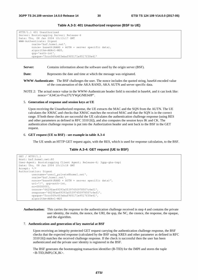
ETSI
ETSI TS 124 109 V14.0.0 (2017-05)303GPP TS 24.109 version 14.0.0 Release 14
Table A.3-3: 401 Unauthorized response (BSF to UE)
HTTP/1.1 401 Unauthorized Server: Bootstrapping Server; Release-6 Date: Thu, 08 Jan 2004 10:13:17 GMT WWW-Authenticate: Digest realm="bsf.home1.net", nonce= base64(RAND + AUTN + server specific data), algorithm=AKAv1-MD5, qop="auth-int", opaque="5ccc069c403ebaf9f0171e9517f30e41"
Server: Contains information about the software used by the origin server (BSF).
Date: Represents the date and time at which the message was originated.
WWW-Authenticate: The BSF challenges the user. The nonce includes the quoted string, base64 encoded value of the concatenation of the AKA RAND, AKA AUTN and server specific data.
NOTE 2: The actual nonce value in the WWW-Authenticate header field is encoded in base64, and it can look like: nonce="A34Cm+Fva37UYWpGNB34JP".
5. Generation of response and session keys at UE
Upon receiving the Unauthorized response, the UE extracts the MAC and the SQN from the AUTN. The UE calculates the XMAC and checks that XMAC matches the received MAC and that the SQN is in the correct range. If both these checks are successful the UE calculates the authentication challenge response (using RES and other parameters as defined in RFC 3310 [6]), and also computes the session keys IK and CK. The authentication challenge response is put into the Authorization header and sent back to the BSF in the GET request.
6. GET request (UE to BSF) - see example in table A.3-4
The UE sends an HTTP GET request again, with the RES, which is used for response calculation, to the BSF.
Table A.3-4: GET request (UE to BSF)
GET / HTTP/1.1 Host: bsf.home1.net:80 User-Agent: Bootstrapping Client Agent; Release-6; 3gpp-gba-tmpi Date: Thu, 08 Jan 2004 10:13:18 GMT Accept: */* Authorization: Digest username="[email protected]", realm="bsf.home1.net", nonce="base64(RAND + AUTN + server specific data)", uri="/", qop=auth-int, nc=00000001, cnonce="6629fae49393a05397450978507c4ef1", response="6629fae49393a05397450978507c4ef1", opaque="5ccc069c403ebaf9f0171e9517f30e41", algorithm=AKAv1-MD5
Authorization: This carries the response to the authentication challenge received in step 4 and contains the private user identity, the realm, the nonce, the URI, the qop, the NC, the cnonce, the response, the opaque, and the algorithm.
7. Authentication and generation of key material at BSF
Upon receiving an integrity protected GET request carrying the authentication challenge response, the BSF checks that the expected response (calculated by the BSF using XRES and other parameter as defined in RFC 3310 [6]) matches the received challenge response. If the check is successful then the user has been authenticated and the private user identity is registered in the BSF.
The BSF generates the bootstrapping transaction identifier (B-TID) for the IMPI and stores the tuple <B-TID,IMPI,CK,IK>.
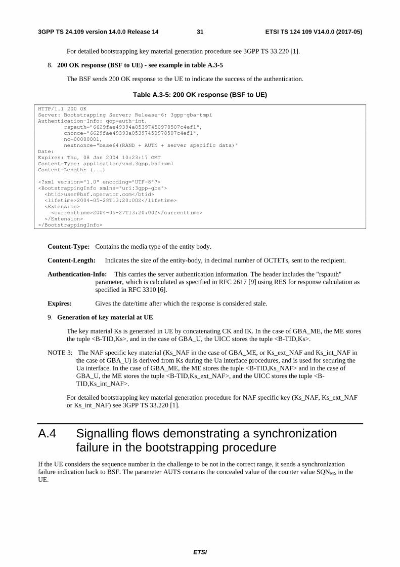
ETSI
ETSI TS 124 109 V14.0.0 (2017-05)313GPP TS 24.109 version 14.0.0 Release 14
For detailed bootstrapping key material generation procedure see 3GPP TS 33.220 [1].
8. 200 OK response (BSF to UE) - see example in table A.3-5
The BSF sends 200 OK response to the UE to indicate the success of the authentication.
Table A.3-5: 200 OK response (BSF to UE)
HTTP/1.1 200 OK Server: Bootstrapping Server; Release-6; 3gpp-gba-tmpi Authentication-Info: qop=auth-int, rspauth="6629fae49394a05397450978507c4ef1", cnonce="6629fae49393a05397450978507c4ef1", nc=00000001, nextnonce="base64(RAND + AUTN + server specific data)" Date: Expires: Thu, 08 Jan 2004 10:23:17 GMT Content-Type: application/vnd.3gpp.bsf+xml Content-Length: (...) <?xml version="1.0" encoding="UTF-8"?> <BootstrappingInfo xmlns="uri:3gpp-gba"> <btid>[email protected]</btid> <lifetime>2004-05-28T13:20:00Z</lifetime> <Extension> <currenttime>2004-05-27T13:20:00Z</currenttime> </Extension> </BootstrappingInfo>
Content-Type: Contains the media type of the entity body.
Content-Length: Indicates the size of the entity-body, in decimal number of OCTETs, sent to the recipient.
Authentication-Info: This carries the server authentication information. The header includes the "rspauth" parameter, which is calculated as specified in RFC 2617 [9] using RES for response calculation as specified in RFC 3310 [6].
Expires: Gives the date/time after which the response is considered stale.
9. Generation of key material at UE
The key material Ks is generated in UE by concatenating CK and IK. In the case of GBA_ME, the ME stores the tuple <B-TID,Ks>, and in the case of GBA_U, the UICC stores the tuple <B-TID,Ks>.
NOTE 3: The NAF specific key material (Ks_NAF in the case of GBA_ME, or Ks_ext_NAF and Ks_int_NAF in the case of GBA_U) is derived from Ks during the Ua interface procedures, and is used for securing the Ua interface. In the case of GBA_ME, the ME stores the tuple <B-TID,Ks_NAF> and in the case of GBA_U, the ME stores the tuple <B-TID,Ks_ext_NAF>, and the UICC stores the tuple <B-TID,Ks_int_NAF>.
For detailed bootstrapping key material generation procedure for NAF specific key (Ks_NAF, Ks_ext_NAF or Ks_int_NAF) see 3GPP TS 33.220 [1].
A.4 Signalling flows demonstrating a synchronization failure in the bootstrapping procedure
If the UE considers the sequence number in the challenge to be not in the correct range, it sends a synchronization failure indication back to BSF. The parameter AUTS contains the concealed value of the counter value SQNMS in the UE.

ETSI
ETSI TS 124 109 V14.0.0 (2017-05)323GPP TS 24.109 version 14.0.0 Release 14
UE BSF HSS
5. SQN invalid, generate AUTS
10. Continue with bootstrapping
1. initial GET
4. 401 Unauthorized
6. GET
9. 401 Unauthorized
2. Zh interface
3. Authentication vector selection
7. Zh interface
8. Authentication vector selection
Figure A.4-1: The bootstrapping procedure in sequence number synchronization failure case.
1-4. Initial bootstrapping steps
Steps 1 through 4 are described in the corresponding steps in clause A.3.
5. SQN invalid, generate AUTS at UE
The UE identifies the sequence number is out of synchronization. The UE generates the AUTS parameter (112 bit value). The AUTS parameter is populated in Authorization header, as specified in RFC 3310 [6].
6. GET request (UE to BSF) - see example in table A.4-1
The UE sends HTTP GET request, with the AUTS parameter to the BSF.
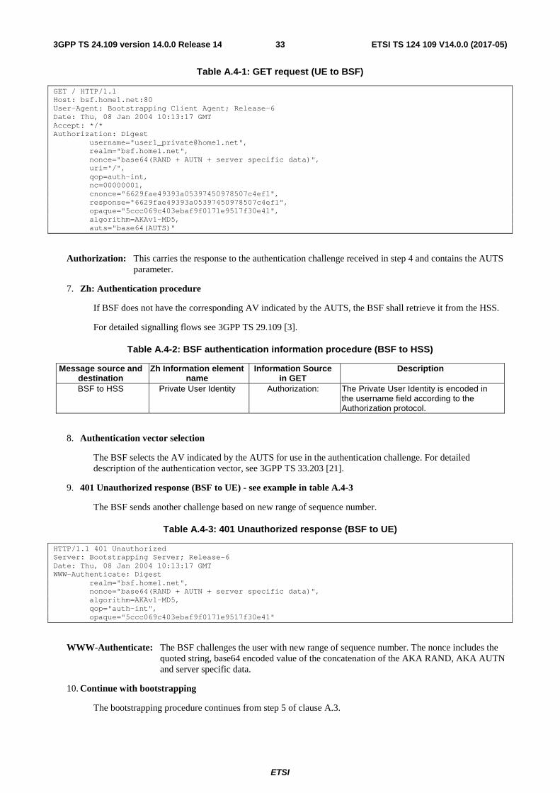
ETSI
ETSI TS 124 109 V14.0.0 (2017-05)333GPP TS 24.109 version 14.0.0 Release 14
Table A.4-1: GET request (UE to BSF)
GET / HTTP/1.1 Host: bsf.home1.net:80 User-Agent: Bootstrapping Client Agent; Release-6 Date: Thu, 08 Jan 2004 10:13:17 GMT Accept: */* Authorization: Digest username="[email protected]", realm="bsf.home1.net", nonce="base64(RAND + AUTN + server specific data)", uri="/", qop=auth-int, nc=00000001, cnonce="6629fae49393a05397450978507c4ef1", response="6629fae49393a05397450978507c4ef1", opaque="5ccc069c403ebaf9f0171e9517f30e41", algorithm=AKAv1-MD5, auts="base64(AUTS)"
Authorization: This carries the response to the authentication challenge received in step 4 and contains the AUTS parameter.
7. Zh: Authentication procedure
If BSF does not have the corresponding AV indicated by the AUTS, the BSF shall retrieve it from the HSS.
For detailed signalling flows see 3GPP TS 29.109 [3].
Table A.4-2: BSF authentication information procedure (BSF to HSS)
Message source and destination
Zh Information element name
Information Source in GET
Description
BSF to HSS Private User Identity Authorization: The Private User Identity is encoded in the username field according to the Authorization protocol.
8. Authentication vector selection
The BSF selects the AV indicated by the AUTS for use in the authentication challenge. For detailed description of the authentication vector, see 3GPP TS 33.203 [21].
9. 401 Unauthorized response (BSF to UE) - see example in table A.4-3
The BSF sends another challenge based on new range of sequence number.
Table A.4-3: 401 Unauthorized response (BSF to UE)
HTTP/1.1 401 Unauthorized Server: Bootstrapping Server; Release-6 Date: Thu, 08 Jan 2004 10:13:17 GMT WWW-Authenticate: Digest realm="bsf.home1.net", nonce="base64(RAND + AUTN + server specific data)", algorithm=AKAv1-MD5, qop="auth-int", opaque="5ccc069c403ebaf9f0171e9517f30e41"
WWW-Authenticate: The BSF challenges the user with new range of sequence number. The nonce includes the quoted string, base64 encoded value of the concatenation of the AKA RAND, AKA AUTN and server specific data.
10. Continue with bootstrapping
The bootstrapping procedure continues from step 5 of clause A.3.
ETSI
ETSI TS 124 109 V14.0.0 (2017-05)343GPP TS 24.109 version 14.0.0 Release 14
Annex A1 (informative): Signalling flows of GBA Push procedure
A1.1 Scope of signalling flows This annex gives examples of signalling flows for the GBA Push procedure.
A1.2 Introduction
A1.2.1 General The GBA Push procedure is executed in order to establish a bootstrapped security association, i.e. bootstrapping session between a Push-NAF and a UE.
A1.2.2 Key required to interpret signalling flows The detailed message contents are not shown in the flows for this subclause as they are not necessarily transported using a text based mechanism. The details for the message contents can be found in 3GPP TS 33.223 [24].
The flows show the signalling exchanges between the following functional entities:
- User Equipment (UE);
- Push-Network Application Function (P-NAF);
- Bootstrapping Server Function (BSF);
- Home Subscriber Server (HSS).
A1.3 Signalling flows demonstrating a successful GBA Push procedure
The overall GBA Push procedure in the successful case is presented in figure A1.3-1. The bootstrapping interface Zh performs the retrieval of an authentication vector by BSF from the HSS, this corresponds to steps 4 and 5 in figure A1.3-1. The bootstrapping interface Zpn performs the retrieval of the GPI by the Push-NAF from the BSF, this corresponds to steps 2 and 7 in figure A1.3-1. The bootstrapping interface Upa is used to transfer the GPI from the Push-NAF to the UE, this corresponds to step 9 in figure A1.3-1. The Zpn interface is defined in 3GPP TS 29.109 [3].

ETSI
ETSI TS 124 109 V14.0.0 (2017-05)353GPP TS 24.109 version 14.0.0 Release 14
Figure A1.3-1: GBA Push signalling
1. Generate GPI Request (Push-NAF)
A Push-NAF needs to establish a shared NAF SA with a UE which is registered for Push services. It knows the identity of the subscriber. The Push-NAF performs the processing described in 3GPP TS 33.223 [24] and generates the GPI Request.
2. Send GPI Request (Push-NAF to BSF)
The Push-NAF sends the GPI Request to the BSF.
3. Initial processing of GPI Requestion (BSF)
Upon receiving the request from the NAF, the BSF performs the processing steps described in 3GPP TS 33.223 [24].
4-5. Zh: Authentication procedure (BSF and HSS)
These steps correspond to Step 2 in figure A.3-1.
6. NAF SA generation (BSF)
The BSF generates the NAF SA as defined in 3GPP TS 33.223 [24].
7. Send GPI Response (BSF to Push-NAF)
The GPI Response generated in the previous step is sent from the BSF to the Push-NAF.
UE P-NAF BSF HSS
1 . Generate GPI Request
2 . GPI Request
3 . Init processing of GPI Request
4 . AV Request
5 . AV Response
6 . NAF SA generation
7 . GPI Response
8 . NAF SA storage
9 . GPI Push
10 . NAF SA storage
ETSI
ETSI TS 124 109 V14.0.0 (2017-05)363GPP TS 24.109 version 14.0.0 Release 14
8. NAF SA storage (Push-NAF)
The Push-NAF stores the information needed to maintain the NAF SA as described in 3GPP TS 33.223 [24].
9. GPI Push (Push-NAF to UE)
The Push-NAF sends a GPI Push to the UE. This can be send over whatever transport method that the Push-NAF wishes to use (e.g. SMS, MMS, SIP Message, etc) The GPI Push message is described in 3GPP TS 33.223 [24].
10. NAF SA Storage (UE)
The UE processes the GPI as described in 3GPP TS 33.223 [24] and stores the NAF SA. The UE does not need to contact the network to correctly generate the NAF SA.

ETSI
ETSI TS 124 109 V14.0.0 (2017-05)373GPP TS 24.109 version 14.0.0 Release 14
Annex B (informative): Signalling flows for HTTP Digest Authentication with bootstrapped security association
B.1 Scope of signalling flows This annex gives examples of signalling flows for using HTTP Digest Authentication with bootstrapped security association.
B.2 Introduction
B.2.1 General A bootstrapping session established using a bootstrapping procedure (cf. clause 4 and annex A) is used between a UE and a NAF. The BSF provides to the NAF a NAF specific key material (Ks_NAF or Ks_ext_NAF and optionally Ks_int_NAF) which is derived from the key material (Ks). The NAF uses this key to authenticate and optionally secure (i.e. integrity protect and encrypt) the communications between it and the UE. The BSF will also provide the NAF the expiration time of the bootstrapping session. When the bootstrapping session becomes invalid the NAF will stop using the session, and indicate to the UE that bootstrapping session has expired and that new session needs to be established.
An example of the signalling flows of the authentication procedure using HTTP Digest authentication [9] is given in clause B.3.
B.2.2 Key required to interpret signalling flows The key to interpret signalling flows is specified in subclause A.2.2.
B.3 Signalling flows demonstrating a successful authentication procedure
The signalling flow in figure B.3-1 describes the generic message exchange between UE and NAF using HTTP Digest Authentication. In this example, the HTTPS client application resides in the ME, i.e., either Ks_NAF or Ks_ext_NAF is used as the key. The conversation can take place inside a server-authenticated TLS (as described in the RFC for TLS defined in annex E of 3GPP TS 33.310 [25]) tunnel in which case TLS session has been established before step 1.
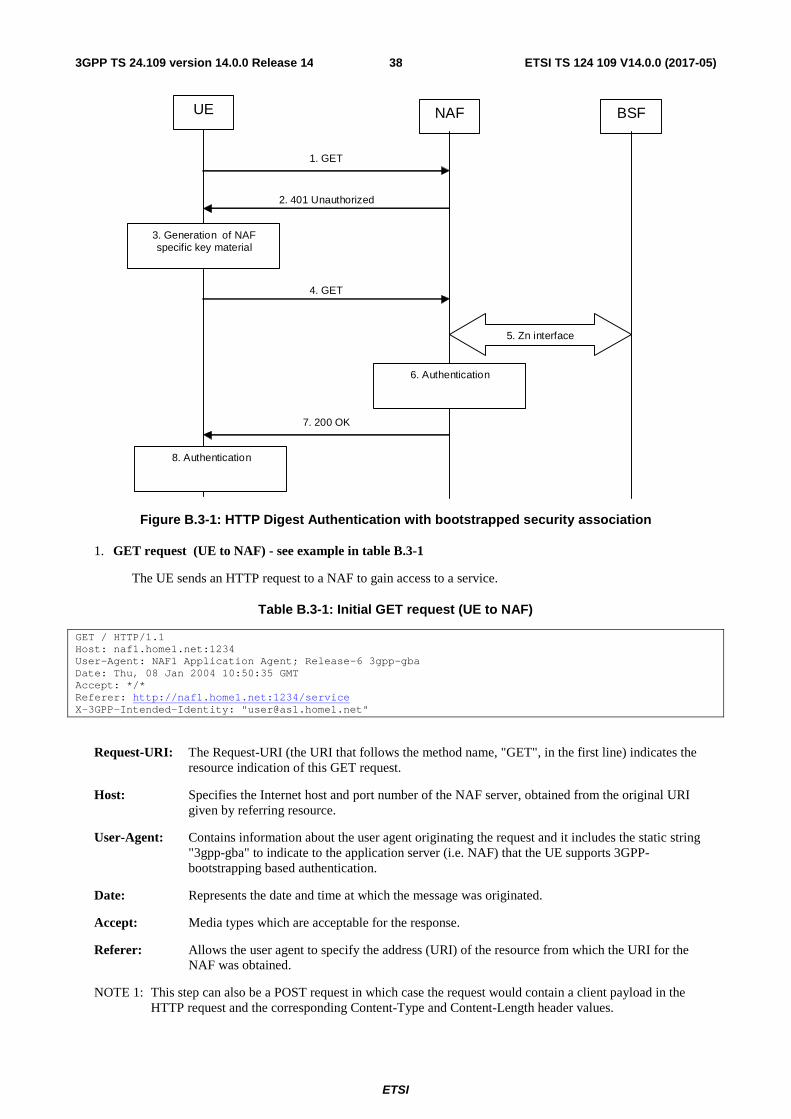
ETSI
ETSI TS 124 109 V14.0.0 (2017-05)383GPP TS 24.109 version 14.0.0 Release 14
UE NAF BSF
3. Generation of NAF specific key material
1. GET
2. 401 Unauthorized
4. GET
7. 200 OK
5. Zn interface
6. Authentication
8. Authentication
Figure B.3-1: HTTP Digest Authentication with bootstrapped security association
1. GET request (UE to NAF) - see example in table B.3-1
The UE sends an HTTP request to a NAF to gain access to a service.
Table B.3-1: Initial GET request (UE to NAF)
GET / HTTP/1.1 Host: naf1.home1.net:1234 User-Agent: NAF1 Application Agent; Release-6 3gpp-gba Date: Thu, 08 Jan 2004 10:50:35 GMT Accept: */* Referer: http://naf1.home1.net:1234/service X-3GPP-Intended-Identity: "[email protected]"
Request-URI: The Request-URI (the URI that follows the method name, "GET", in the first line) indicates the resource indication of this GET request.
Host: Specifies the Internet host and port number of the NAF server, obtained from the original URI given by referring resource.
User-Agent: Contains information about the user agent originating the request and it includes the static string "3gpp-gba" to indicate to the application server (i.e. NAF) that the UE supports 3GPP-bootstrapping based authentication.
Date: Represents the date and time at which the message was originated.
Accept: Media types which are acceptable for the response.
Referer: Allows the user agent to specify the address (URI) of the resource from which the URI for the NAF was obtained.
NOTE 1: This step can also be a POST request in which case the request would contain a client payload in the HTTP request and the corresponding Content-Type and Content-Length header values.

ETSI
ETSI TS 124 109 V14.0.0 (2017-05)393GPP TS 24.109 version 14.0.0 Release 14
2. 401 Unauthorized response (NAF to UE) - see example in table B.3-2
Upon receiving an HTTP request that contains static string "3gpp-gba" in the User-Agent header, NAF can choose to authenticate the UE using bootstrapped security association. If NAF chooses to authenticate the UE using bootstrapped security association, it responds with HTTP response code 401 "Unauthorized" which contains a WWW-Authenticate header. The header instructs the UE to use HTTP Digest Authentication with a bootstrapped security association.
Table B.3-2: 401 Unauthorized response (NAF to UE)
HTTP/1.1 401 Unauthorized Server: Apache/1.3.22 (Unix) mod_perl/1.27 Date: Thu, 08 Jan 2004 10:50:35 GMT WWW-Authenticate: Digest realm="[email protected]",
nonce="6629fae49393a05397450978507c4ef1", algorithm=MD5, qop="auth,auth-int", opaque="5ccc069c403ebaf9f0171e9517f30e41"
Server: Contains information about the software used by the origin server (NAF).
Date: Represents the date and time at which the message was originated.
WWW-Authenticate: The NAF challenges the user. The header instructs the UE to use HTTP Digest Authentication with a bootstrapped security association.
The options for the quality of protection (qop) attribute is by default "auth-int" meaning that the payload of the following HTTP requests and responses should integrity protected. If the conversation is taking place inside a server-authenticated TLS tunnel, the options for the qop attribute can also contain "auth" meaning that the payload of the following HTTP requests and responses are not protected by HTTP Digest. The integrity protection is handled on the TLS layer instead.
The realm attribute contains two parts delimited by "@" sign. The first part is a constant string "3GPP-bootstrapping" instructing the UE to use a bootstrapped security association. The second part is the FQDN of the NAF.
3. Generation of NAF specific keys at UE
UE verifies that the second part of the realm attribute does correspond to the server it is talking to. In particular, if the conversation is taking place inside a server-authenticated TLS tunnel, the UE shall verify that the server name in the server's TLS certificate matches the server name in the realm attribute of the WWW-Authenticate header.
UE derives the NAF specific key material Ks_(ext)_NAF as specified in 3GPP TS 33.220 [1].
NOTE 2: If UE does not have a bootstrapped security association available, it obtains one by running bootstrapping procedure over Ub interface
4. GET request (UE to NAF) - see example in table B.3-3
UE generates the HTTP request by calculating the Authorization header values using the bootstrapping transaction identifier B-TID it received from the BSF as the username and the NAF specific key material Ks_(ext)_NAF (base64 encoded) as the password, and sends the request to NAF.
Table B.3-3: GET request (UE to NAF)
GET / HTTP/1.1 Host: naf1.home1.net:1234 User-Agent: NAF1 Application Agent; Release-6 3gpp-gba Date: Thu, 08 Jan 2004 10:50:35 GMT Accept: */* Referer: http://naf1.home1.net:1234/service X-3GPP-Intended-Identity: "[email protected]" Authorization: Digest username="(B-TID)", realm="[email protected]",
nonce="a6332ffd2d234==", uri="/", qop=auth-int, nc=00000001, cnonce="6629fae49393a05397450978507c4ef1", response="6629fae49393a05397450978507c4ef1", opaque="5ccc069c403ebaf9f0171e9517f30e41", algorithm=MD5
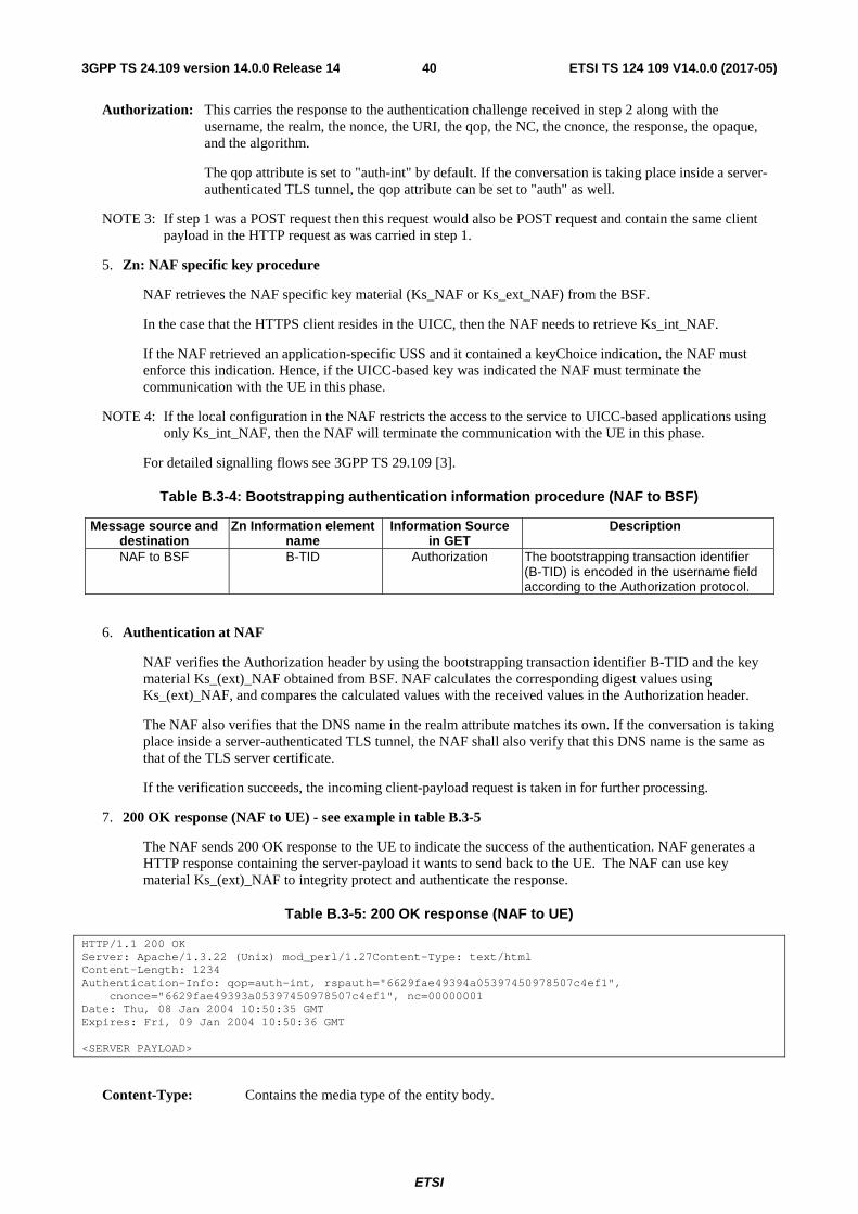
ETSI
ETSI TS 124 109 V14.0.0 (2017-05)403GPP TS 24.109 version 14.0.0 Release 14
Authorization: This carries the response to the authentication challenge received in step 2 along with the username, the realm, the nonce, the URI, the qop, the NC, the cnonce, the response, the opaque, and the algorithm.
The qop attribute is set to "auth-int" by default. If the conversation is taking place inside a server-authenticated TLS tunnel, the qop attribute can be set to "auth" as well.
NOTE 3: If step 1 was a POST request then this request would also be POST request and contain the same client payload in the HTTP request as was carried in step 1.
5. Zn: NAF specific key procedure
NAF retrieves the NAF specific key material (Ks_NAF or Ks_ext_NAF) from the BSF.
In the case that the HTTPS client resides in the UICC, then the NAF needs to retrieve Ks_int_NAF.
If the NAF retrieved an application-specific USS and it contained a keyChoice indication, the NAF must enforce this indication. Hence, if the UICC-based key was indicated the NAF must terminate the communication with the UE in this phase.
NOTE 4: If the local configuration in the NAF restricts the access to the service to UICC-based applications using only Ks_int_NAF, then the NAF will terminate the communication with the UE in this phase.
For detailed signalling flows see 3GPP TS 29.109 [3].
Table B.3-4: Bootstrapping authentication information procedure (NAF to BSF)
Message source and destination
Zn Information element name
Information Source in GET
Description
NAF to BSF B-TID Authorization The bootstrapping transaction identifier (B-TID) is encoded in the username field according to the Authorization protocol.
6. Authentication at NAF
NAF verifies the Authorization header by using the bootstrapping transaction identifier B-TID and the key material Ks_(ext)_NAF obtained from BSF. NAF calculates the corresponding digest values using Ks_(ext)_NAF, and compares the calculated values with the received values in the Authorization header.
The NAF also verifies that the DNS name in the realm attribute matches its own. If the conversation is taking place inside a server-authenticated TLS tunnel, the NAF shall also verify that this DNS name is the same as that of the TLS server certificate.
If the verification succeeds, the incoming client-payload request is taken in for further processing.
7. 200 OK response (NAF to UE) - see example in table B.3-5
The NAF sends 200 OK response to the UE to indicate the success of the authentication. NAF generates a HTTP response containing the server-payload it wants to send back to the UE. The NAF can use key material Ks_(ext)_NAF to integrity protect and authenticate the response.
Table B.3-5: 200 OK response (NAF to UE)
HTTP/1.1 200 OK Server: Apache/1.3.22 (Unix) mod_perl/1.27Content-Type: text/html Content-Length: 1234 Authentication-Info: qop=auth-int, rspauth="6629fae49394a05397450978507c4ef1",
cnonce="6629fae49393a05397450978507c4ef1", nc=00000001 Date: Thu, 08 Jan 2004 10:50:35 GMT Expires: Fri, 09 Jan 2004 10:50:36 GMT <SERVER PAYLOAD>
Content-Type: Contains the media type of the entity body.
ETSI
ETSI TS 124 109 V14.0.0 (2017-05)413GPP TS 24.109 version 14.0.0 Release 14
Content-Length: Indicates the size of the entity-body, in decimal number of OCTETs, sent to the recipient.
Authentication-Info: This carries the protection
Expires: Gives the date/time after which the response is considered stale.
8. Authentication at UE
UE receives the response and verifies the Authentication-Info header. If the verification succeeds, the UE can accept the server-payload for further processing.
NOTE 4: Additional messages can be exchanged using steps 4 through 8 as many times as is necessary. The following HTTP requests and responses are constructed according to RFC 2617 [9].
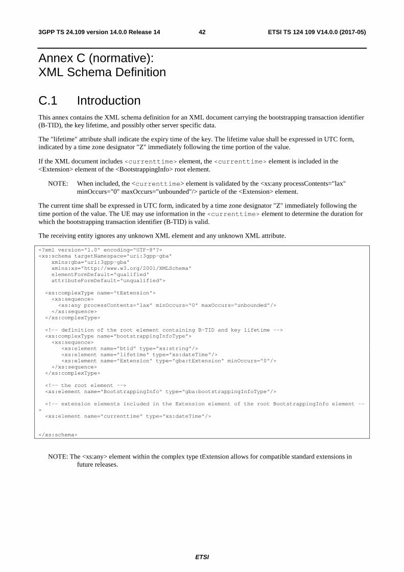
ETSI
ETSI TS 124 109 V14.0.0 (2017-05)423GPP TS 24.109 version 14.0.0 Release 14
Annex C (normative): XML Schema Definition
C.1 Introduction This annex contains the XML schema definition for an XML document carrying the bootstrapping transaction identifier (B-TID), the key lifetime, and possibly other server specific data.
The "lifetime" attribute shall indicate the expiry time of the key. The lifetime value shall be expressed in UTC form, indicated by a time zone designator "Z" immediately following the time portion of the value.
If the XML document includes <currenttime> element, the <currenttime> element is included in the <Extension> element of the <BootstrappingInfo> root element.
NOTE: When included, the <currenttime> element is validated by the <xs:any processContents="lax" minOccurs="0" maxOccurs="unbounded"/> particle of the <Extension> element.
The current time shall be expressed in UTC form, indicated by a time zone designator "Z" immediately following the time portion of the value. The UE may use information in the <currenttime> element to determine the duration for which the bootstrapping transaction identifier (B-TID) is valid.
The receiving entity ignores any unknown XML element and any unknown XML attribute.
<?xml version="1.0" encoding="UTF-8"?> <xs:schema targetNamespace="uri:3gpp-gba" xmlns:gba="uri:3gpp-gba" xmlns:xs="http://www.w3.org/2001/XMLSchema" elementFormDefault="qualified" attributeFormDefault="unqualified"> <xs:complexType name="tExtension"> <xs:sequence> <xs:any processContents="lax" minOccurs="0" maxOccurs="unbounded"/> </xs:sequence> </xs:complexType> <!-- definition of the root element containing B-TID and key lifetime --> <xs:complexType name="bootstrappingInfoType"> <xs:sequence> <xs:element name="btid" type="xs:string"/> <xs:element name="lifetime" type="xs:dateTime"/> <xs:element name="Extension" type="gba:tExtension" minOccurs="0"/> </xs:sequence> </xs:complexType> <!-- the root element --> <xs:element name="BootstrappingInfo" type="gba:bootstrappingInfoType"/> <!-- extension elements included in the Extension element of the root BootstrappingInfo element --> <xs:element name="currenttime" type="xs:dateTime"/> </xs:schema>
NOTE: The <xs:any> element within the complex type tExtension allows for compatible standard extensions in future releases.

ETSI
ETSI TS 124 109 V14.0.0 (2017-05)433GPP TS 24.109 version 14.0.0 Release 14
Annex D (informative): Signalling flows for Authentication Proxy
D.1 Scope of signalling flows This annex gives examples of signalling flows for using AP in GAA.
D.2 Introduction A bootstrapping session (established using a bootstrapping procedure, cf. clause 4 and annex A) is used between a UE and an authentication proxy (AP) that is functioning as a NAF. The BSF provides to the AP an AP specific key material (Ks_NAF or Ks_ext_NAF and optionally Ks_int_NAF), which is derived from the key material (Ks). The AP uses this key to authenticate and optionally secure (i.e. integrity protect with HTTP Digest using "auth-int" qop option, or integrity protect and encrypt with PSK TLS) the communications between it and the UE. The BSF will also provide the AP the expiration time of the bootstrapping session. When the bootstrapping session becomes invalid the AP will stop using the session, and indicate to the UE that bootstrapping session has expired and that new session needs to be established.
The AP functions as a reverse proxy. After the AP has authenticated and optionally secured the communcation between it and the UE, the AP will forward the incoming HTTP requests from the UE to the correct appliation server (AS) behind the AP. There can be multiple application servers behind the AP.
NOTE: As consequence of the fact that the UE assumes it is communicating with the AS, not the AP, the AP might need to use different NAF specific keys per UE because (i) the UE will use the hostname of the AS (i.e., NAF_ID) when deriving the NAF specific key, (ii) the AP is doing virtual name based hosting, i.e., has reverse proxy functionality, and (iii) the UE can communicate through the AP with several ASes at the same time.
An example of the signalling flows of the authentication procedure between a UE, an AP, and an AS is given in clause D.3.
D.2.1 Key required to interpret signalling flows The key to interpret signalling flows specified in subclause A.2.2.
D.3 Signalling flow demonstrating a successful authentication procedure
The signalling flow in figure D.3-1 describes the generic message exchange between a UE, a AP, and an AS using HTTP. In this example, the HTTP client application resides in the ME, i.e., either Ks_NAF or Ks_ext_NAF is used as the key. The conversation between the UE and the AP can take place inside a server-authenticated TLS (as described in the RFC for TLS defined in annex E of 3GPP TS 33.310 [25]) tunnel in which case TLS session has been established before step 1.

ETSI
ETSI TS 124 109 V14.0.0 (2017-05)443GPP TS 24.109 version 14.0.0 Release 14
UE AS
3. Generation of NAF specific key material
1. GET
2. 401 Unauthorized
4. GET (authenticated)
6. GET (with UID)
7. AS specific logic
8. 200 OK
10. 200 OK
AP
5. Validate authentication and authorize request
9. Add Authentication-Info
11. Process response
Figure D.3-1: Successful authentiation with AP and AS
1. GET request (UE to AP) - see example in table D.3-1
The UE sends an HTTP request to a AP to gain access to a service.
Table D.3-1: Initial GET request (UE toAP)
GET / HTTP/1.1 Host: as1.home1.net:1234 User-Agent: NAF1 Application Agent; Release-6 3gpp-gba Date: Thu, 08 Jan 2004 10:50:35 GMT Accept: */* Referer: http://as1.home1.net:1234/service
Request-URI: The Request-URI (the URI that follows the method name, "GET", in the first line) indicates the resource indication of this GET request.
Host: Specifies the Internet host and port number of the AS, obtained from the original URI given by referring resource.
User-Agent: Contains information about the user agent originating the request and it includes the static string "3gpp-gba" to indicate to the application server (i.e. NAF) that the UE supports 3GPP-bootstrapping based authentication.
Date: Represents the date and time at which the message was originated.
Accept: Media types which are acceptable for the response.
Referer: Allows the user agent to specify the address (URI) of the resource from which the URI for the AS was obtained.
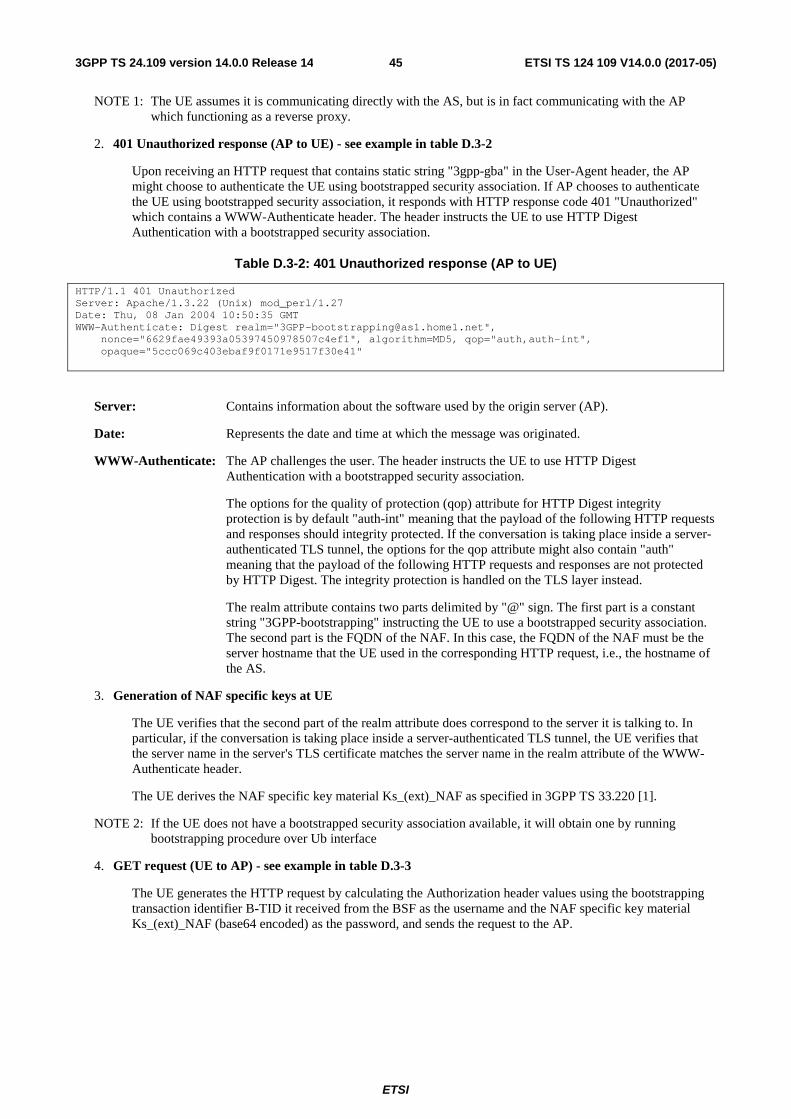
ETSI
ETSI TS 124 109 V14.0.0 (2017-05)453GPP TS 24.109 version 14.0.0 Release 14
NOTE 1: The UE assumes it is communicating directly with the AS, but is in fact communicating with the AP which functioning as a reverse proxy.
2. 401 Unauthorized response (AP to UE) - see example in table D.3-2
Upon receiving an HTTP request that contains static string "3gpp-gba" in the User-Agent header, the AP might choose to authenticate the UE using bootstrapped security association. If AP chooses to authenticate the UE using bootstrapped security association, it responds with HTTP response code 401 "Unauthorized" which contains a WWW-Authenticate header. The header instructs the UE to use HTTP Digest Authentication with a bootstrapped security association.
Table D.3-2: 401 Unauthorized response (AP to UE)
HTTP/1.1 401 Unauthorized Server: Apache/1.3.22 (Unix) mod_perl/1.27 Date: Thu, 08 Jan 2004 10:50:35 GMT WWW-Authenticate: Digest realm="[email protected]",
nonce="6629fae49393a05397450978507c4ef1", algorithm=MD5, qop="auth,auth-int", opaque="5ccc069c403ebaf9f0171e9517f30e41"
Server: Contains information about the software used by the origin server (AP).
Date: Represents the date and time at which the message was originated.
WWW-Authenticate: The AP challenges the user. The header instructs the UE to use HTTP Digest Authentication with a bootstrapped security association.
The options for the quality of protection (qop) attribute for HTTP Digest integrity protection is by default "auth-int" meaning that the payload of the following HTTP requests and responses should integrity protected. If the conversation is taking place inside a server-authenticated TLS tunnel, the options for the qop attribute might also contain "auth" meaning that the payload of the following HTTP requests and responses are not protected by HTTP Digest. The integrity protection is handled on the TLS layer instead.
The realm attribute contains two parts delimited by "@" sign. The first part is a constant string "3GPP-bootstrapping" instructing the UE to use a bootstrapped security association. The second part is the FQDN of the NAF. In this case, the FQDN of the NAF must be the server hostname that the UE used in the corresponding HTTP request, i.e., the hostname of the AS.
3. Generation of NAF specific keys at UE
The UE verifies that the second part of the realm attribute does correspond to the server it is talking to. In particular, if the conversation is taking place inside a server-authenticated TLS tunnel, the UE verifies that the server name in the server's TLS certificate matches the server name in the realm attribute of the WWW-Authenticate header.
The UE derives the NAF specific key material Ks_(ext)_NAF as specified in 3GPP TS 33.220 [1].
NOTE 2: If the UE does not have a bootstrapped security association available, it will obtain one by running bootstrapping procedure over Ub interface
4. GET request (UE to AP) - see example in table D.3-3
The UE generates the HTTP request by calculating the Authorization header values using the bootstrapping transaction identifier B-TID it received from the BSF as the username and the NAF specific key material Ks_(ext)_NAF (base64 encoded) as the password, and sends the request to the AP.
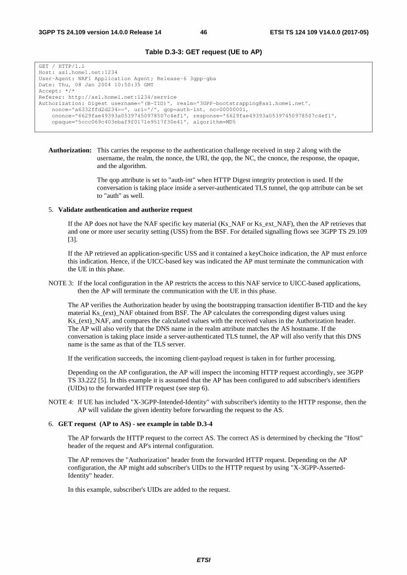
ETSI
ETSI TS 124 109 V14.0.0 (2017-05)463GPP TS 24.109 version 14.0.0 Release 14
Table D.3-3: GET request (UE to AP)
GET / HTTP/1.1 Host: as1.home1.net:1234 User-Agent: NAF1 Application Agent; Release-6 3gpp-gba Date: Thu, 08 Jan 2004 10:50:35 GMT Accept: */* Referer: http://as1.home1.net:1234/service Authorization: Digest username="(B-TID)", realm="[email protected]",
nonce="a6332ffd2d234==", uri="/", qop=auth-int, nc=00000001, cnonce="6629fae49393a05397450978507c4ef1", response="6629fae49393a05397450978507c4ef1", opaque="5ccc069c403ebaf9f0171e9517f30e41", algorithm=MD5
Authorization: This carries the response to the authentication challenge received in step 2 along with the username, the realm, the nonce, the URI, the qop, the NC, the cnonce, the response, the opaque, and the algorithm.
The qop attribute is set to "auth-int" when HTTP Digest integrity protection is used. If the conversation is taking place inside a server-authenticated TLS tunnel, the qop attribute can be set to "auth" as well.
5. Validate authentication and authorize request
If the AP does not have the NAF specific key material (Ks_NAF or Ks_ext_NAF), then the AP retrieves that and one or more user security setting (USS) from the BSF. For detailed signalling flows see 3GPP TS 29.109 [3].
If the AP retrieved an application-specific USS and it contained a keyChoice indication, the AP must enforce this indication. Hence, if the UICC-based key was indicated the AP must terminate the communication with the UE in this phase.
NOTE 3: If the local configuration in the AP restricts the access to this NAF service to UICC-based applications, then the AP will terminate the communication with the UE in this phase.
The AP verifies the Authorization header by using the bootstrapping transaction identifier B-TID and the key material Ks_(ext)_NAF obtained from BSF. The AP calculates the corresponding digest values using Ks_(ext)_NAF, and compares the calculated values with the received values in the Authorization header. The AP will also verify that the DNS name in the realm attribute matches the AS hostname. If the conversation is taking place inside a server-authenticated TLS tunnel, the AP will also verify that this DNS name is the same as that of the TLS server.
If the verification succeeds, the incoming client-payload request is taken in for further processing.
Depending on the AP configuration, the AP will inspect the incoming HTTP request accordingly, see 3GPP TS 33.222 [5]. In this example it is assumed that the AP has been configured to add subscriber's identifiers (UIDs) to the forwarded HTTP request (see step 6).
NOTE 4: If UE has included "X-3GPP-Intended-Identity" with subscriber's identity to the HTTP response, then the AP will validate the given identity before forwarding the request to the AS.
6. GET request (AP to AS) - see example in table D.3-4
The AP forwards the HTTP request to the correct AS. The correct AS is determined by checking the "Host" header of the request and AP's internal configuration.
The AP removes the "Authorization" header from the forwarded HTTP request. Depending on the AP configuration, the AP might add subscriber's UIDs to the HTTP request by using "X-3GPP-Asserted-Identity" header.
In this example, subscriber's UIDs are added to the request.

ETSI
ETSI TS 124 109 V14.0.0 (2017-05)473GPP TS 24.109 version 14.0.0 Release 14
Table D.3-4: GET request (AP to AS)
GET / HTTP/1.1 Host: as1.home1.net:1234 User-Agent: NAF1 Application Agent; Release-6 3gpp-gba Date: Thu, 08 Jan 2004 10:50:35 GMT Accept: */* Referer: http://as1.home1.net:1234/service X-3GPP-Asserted-Identity: "[email protected]", "[email protected]"
Content-Type: Contains the media type of the entity body.
Content-Length: Indicates the size of the entity-body, in decimal number of OCTETs, sent to the recipient.
Authentication-Info: This carries the protection
Expires: Gives the date/time after which the response is considered stale.
X-3GPP-Asserted-Identity: This header is added by the AP and carries the list of subscriber's identities to the AS.
7. AS specific logic at AS
The AS processes the incoming HTTP request and extracts the UIDs from the "X-3GPP-Asserted-Identity" header.
8. 200 OK response (AS to AP) - see example in table D.3-5
The AS returns a HTTP response to the AP with service specific payload.
Table D.3-5: 200 OK response (AS to AP)
HTTP/1.1 200 OK Server: Apache/1.3.22 (Unix) mod_perl/1.27 Content-Type: text/html Content-Length: (...) Date: Thu, 08 Jan 2004 10:50:35 GMT Expires: Fri, 09 Jan 2004 10:50:36 GMT <SERVER PAYLOAD>
Content-Type: Contains the media type of the entity body.
Content-Length: Indicates the size of the entity-body, in decimal number of OCTETs, sent to the recipient.
Expires: Gives the date/time after which the response is considered stale.
9. Add Authentication-Info header at AP
The AP calculates and adds the "Authentication-Info" header to the HTTP response that forwarded to the UE.
10. 200 OK response (AP to UE) - see example in table D.3-6
The AP forwards the HTTP response to the UE.

ETSI
ETSI TS 124 109 V14.0.0 (2017-05)483GPP TS 24.109 version 14.0.0 Release 14
Table D.3-6: 200 OK response (AP to UE)
HTTP/1.1 200 OK Server: Apache/1.3.22 (Unix) mod_perl/1.27 Content-Type: text/html Content-Length: 1234 Date: Thu, 08 Jan 2004 10:50:35 GMT Expires: Fri, 09 Jan 2004 10:50:36 GMT Authentication-Info: qop=auth-int, rspauth="6629fae49394a05397450978507c4ef1",
cnonce="6629fae49393a05397450978507c4ef1", nc=00000001 <SERVER PAYLOAD>
Authentication-Info: This header is inserted by the AP to the request. The values in the header are calculated by the AP.
11. Process response at UE
The UE receives the response and verifies the Authentication-Info header. If the verification succeeds, the UE can accept the server-payload for further processing.
NOTE 5: Additional messages can be exchanged using steps 4 through 11 as many times as is necessary. The HTTP Digest releated headers in the following HTTP requests and responses must be constructed according to RFC 2617 [8].

ETSI
ETSI TS 124 109 V14.0.0 (2017-05)493GPP TS 24.109 version 14.0.0 Release 14
Annex E (informative): Signalling flows for PKI portal
E.1 Scope of signalling flows This annex gives examples of signalling flows for the subscriber certificate enrolment and the CA certificate delivery.
E.2 Introduction
E.2.1 General A bootstrapping session established using a bootstrapping procedure (cf., clause 4 and annex A) is used between a UE and a PKI portal. The BSF provides to the PKI portal a NAF specific key material (Ks_NAF or Ks_ext_NAF) which is derived from the key material (Ks). The PKI portal uses this key to authenticate and optionally secure (i.e. integrity protect and encrypt) the communications between it and the UE. The BSF will also provide the PKI portal the expiration time of the bootstrapping session.
E.2.2 Key required to interpret signalling flows The key to interpret signalling flows is specified in subclause A.2.2.
E.3 Signalling flows demonstrating a successful subscriber certificate enrolment
E.3.1 Simple subscriber certificate enrolment The signalling flow in figure E.3.1-1 describes the message exchange between UE and PKI portal when UE wants to enrol a subscriber certificate. The messaging can take place inside a server-authenticated TLS (as described in the RFC for TLS defined in annex E of 3GPP TS 33.310 [25]) tunnel in which case TLS session has been established before step 1.

ETSI
ETSI TS 124 109 V14.0.0 (2017-05)503GPP TS 24.109 version 14.0.0 Release 14
UE PKI portal BSF
3. Generation of NAF specific key material
1. Initial enrolment request
2. 401 Unauthorized
4. Authenticated enrolment request
7. Delivery of subscriber certificate
5. Zn interface
6. Authentication and certificate generation
8. Authentication
Figure E.3.1-1: Successful subscriber certificate enrolment.
1. Initial enrolment request (UE to PKI portal) - see example in table E.3.1-1
The UE sends an HTTP request to the PKI portal containing a PKCS#10 certification request.
Table E.3.1-1: Initial enrolment request (UE to PKI portal)
POST /enrol?response=single HTTP/1.1 Host: pkiportal.home1.net:1234 Content-Type: application/x-pkcs10 Content-Length: (...) User-Agent: SCEnrolmentAgent; Release-6 3gpp-gba Date: Thu, 08 Jan 2004 10:50:35 GMT Accept: */* Referer: http://pkiportal.home1.net:1234/service ----- BEGIN CERTIFICATE REQUEST ----- <PKCS#10 BLOB> ----- END CERTIFICATE REQUEST -----
Request-URI: The Request-URI (the URI that follows the method name, "POST", in the first line) indicates the resource of this POST request. The Request-URI contains the parameter "response" which is set to "single" to indicate to the PKI portal the desired response type, i.e. just the subscriber certificate is requested to be delivered.
Host: Specifies the Internet host and port number of the PKI portal server, obtained from the original URI given by referring resource.
Content-Type: Contains the media type "application/x-pkcs10", i.e. the PKCS#10.
Content-Length: Indicates the size of the entity-body, in decimal number of OCTETs, sent to the recipient.
User-Agent: Contains information about the user agent originating the request and it will include the static string "3gpp-gba" to indicate to the application server (i.e., NAF) that the UE supports 3GPP-bootstrapping based authentication.
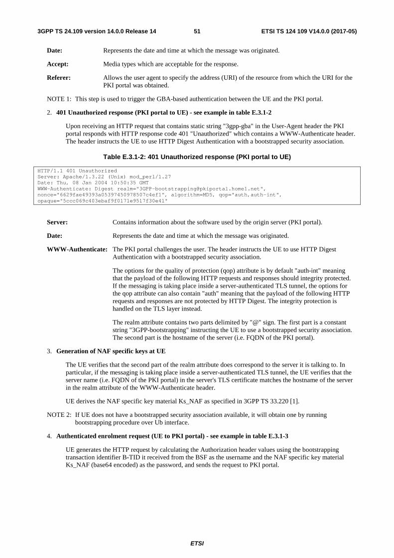
ETSI
ETSI TS 124 109 V14.0.0 (2017-05)513GPP TS 24.109 version 14.0.0 Release 14
Date: Represents the date and time at which the message was originated.
Accept: Media types which are acceptable for the response.
Referer: Allows the user agent to specify the address (URI) of the resource from which the URI for the PKI portal was obtained.
NOTE 1: This step is used to trigger the GBA-based authentication between the UE and the PKI portal.
2. 401 Unauthorized response (PKI portal to UE) - see example in table E.3.1-2
Upon receiving an HTTP request that contains static string "3gpp-gba" in the User-Agent header the PKI portal responds with HTTP response code 401 "Unauthorized" which contains a WWW-Authenticate header. The header instructs the UE to use HTTP Digest Authentication with a bootstrapped security association.
Table E.3.1-2: 401 Unauthorized response (PKI portal to UE)
HTTP/1.1 401 Unauthorized Server: Apache/1.3.22 (Unix) mod_perl/1.27 Date: Thu, 08 Jan 2004 10:50:35 GMT WWW-Authenticate: Digest realm="[email protected]", nonce="6629fae49393a05397450978507c4ef1", algorithm=MD5, qop="auth,auth-int", opaque="5ccc069c403ebaf9f0171e9517f30e41"
Server: Contains information about the software used by the origin server (PKI portal).
Date: Represents the date and time at which the message was originated.
WWW-Authenticate: The PKI portal challenges the user. The header instructs the UE to use HTTP Digest Authentication with a bootstrapped security association.
The options for the quality of protection (qop) attribute is by default "auth-int" meaning that the payload of the following HTTP requests and responses should integrity protected. If the messaging is taking place inside a server-authenticated TLS tunnel, the options for the qop attribute can also contain "auth" meaning that the payload of the following HTTP requests and responses are not protected by HTTP Digest. The integrity protection is handled on the TLS layer instead.
The realm attribute contains two parts delimited by "@" sign. The first part is a constant string "3GPP-bootstrapping" instructing the UE to use a bootstrapped security association. The second part is the hostname of the server (i.e. FQDN of the PKI portal).
3. Generation of NAF specific keys at UE
The UE verifies that the second part of the realm attribute does correspond to the server it is talking to. In particular, if the messaging is taking place inside a server-authenticated TLS tunnel, the UE verifies that the server name (i.e. FQDN of the PKI portal) in the server's TLS certificate matches the hostname of the server in the realm attribute of the WWW-Authenticate header.
UE derives the NAF specific key material Ks_NAF as specified in 3GPP TS 33.220 [1].
NOTE 2: If UE does not have a bootstrapped security association available, it will obtain one by running bootstrapping procedure over Ub interface.
4. Authenticated enrolment request (UE to PKI portal) - see example in table E.3.1-3
UE generates the HTTP request by calculating the Authorization header values using the bootstrapping transaction identifier B-TID it received from the BSF as the username and the NAF specific key material Ks_NAF (base64 encoded) as the password, and sends the request to PKI portal.

ETSI
ETSI TS 124 109 V14.0.0 (2017-05)523GPP TS 24.109 version 14.0.0 Release 14
Table E.3.1-3: Authenticated enrolment request (UE to PKI portal)
POST /enrol?response=single HTTP/1.1 Host: pkiportal.home1.net:1234 Content-Type: application/pkcs10 Content-Length: (...) User-Agent: SCEnrolmentAgent; Release-6 3gpp-gba Date: Thu, 08 Jan 2004 10:50:35 GMT Accept: */* Referer: http://pkiportal.home1.net:1234/service Authorization: Digest username="(B-TID)", realm="[email protected]",
nonce="a6332ffd2d234==", uri="/enrol?response=single", qop=auth-int, nc=00000001, cnonce="6629fae49393a05397450978507c4ef1", response="6629fae49393a05397450978507c4ef1", opaque="5ccc069c403ebaf9f0171e9517f30e41", algorithm=MD5
----- BEGIN CERTIFICATE REQUEST ----- <PKCS#10 BLOB> ----- END CERTIFICATE REQUEST -----
Authorization: This carries the response to the authentication challenge received in step 2 along with the username, the realm, the nonce, the URI, the qop, the NC, the cnonce, the response, the opaque, and the algorithm.
The qop attribute is set to "auth-int" by default. If the messaging is taking place inside a server-authenticated TLS tunnel, the qop attribute can be set to "auth" as well.
NOTE 3: If step 1 was a POST request then this request would also be POST request and contain the same client payload in the HTTP request as was carried in step 1.
5. Zn: NAF specific key procedure
PKI portal retrieves the NAF specific key material (Ks_NAF) and subscriber's user security setting from the BSF.
NOTE 4: Subscriber's user security setting for PKI portal consists of flags that indicate whether certain type certificate is authorized to be issued to the subscriber. There are two certificate types: authentication certificate and non-repudiation certificate.
For detailed signalling flows see 3GPP TS 29.109 [3].
Table E.3.1-4: Bootstrapping authentication information procedure (PKI portal to BSF)
Message source and destination
Zn Information element name
Information Source in GET
Description
NAF to BSF B-TID Authorization The bootstrapping transaction identifier (B-TID) is encoded in the username field according to the Authorization protocol.
6. Authentication and certificate generation at PKI portal
PKI portal verifies the Authorization header by using the bootstrapping transaction identifier B-TID and the key material Ks_NAF obtained from BSF. PKI portal calculates the corresponding digest values using Ks_NAF, and compares the calculated values with the received values in the Authorization header.
The PKI portal also verifies that the hostname (i.e. its FQDN) in the realm attribute matches its own. If the messaging is taking place inside a server-authenticated TLS tunnel, the PKI portal also verifies that this hostname is the same as that of the TLS server.
If the verification succeeds, the incoming client-payload request is taken in for further processing. The PKI portal continues processing of the PKCS#10 request according to its internal policies. The PKI portal verifies that the subscriber is allowed to receive the particular type of certificate indicate in the PKCS#10 request by checking subscriber's user security setting received from the BSF in step 5.
NOTE 5: The procedures for generating the subscriber certificate are outside the scope.
7. Delivery of subscriber certificate (PKI portal to UE) - see example in table E.3.1-5

ETSI
ETSI TS 124 109 V14.0.0 (2017-05)533GPP TS 24.109 version 14.0.0 Release 14
The PKI portal sends 200 OK response to the UE to indicate the success of the authentication and the subscriber certificate enrolment. The PKI portal generates a HTTP response containing the enrolled subscriber certificate. The PKI portal can use key material Ks_NAF to integrity protect and authenticate the response.
Table E.3.1-5: Delivery of subscriber certificate (PKI portal to UE)
HTTP/1.1 200 OK Server: Apache/1.3.22 (Unix) mod_perl/1.27 Content-Type: text/html Content-Type: application/x-x509-user-cert Content-Length: (...) Authentication-Info: qop=auth-int, rspauth="6629fae49394a05397450978507c4ef1", cnonce="6629fae49393a05397450978507c4ef1", nc=00000001 Date: Thu, 08 Jan 2004 10:50:35 GMT Expires: Fri, 09 Jan 2004 10:50:36 GMT ----- BEGIN CERTIFICATE ----- <Subscriber certificate BLOB> ----- END CERTIFICATE -----
Content-Type: Contains the media type "application/x-x509-user-cert", i.e. X.509 certificate.
Content-Length: Indicates the size of the entity-body, in decimal number of OCTETs, sent to the recipient.
Authentication-Info: This carries the protection
Expires: Gives the date/time after which the response is considered stale.
8. Authentication at UE
The UE receives the response and verifies the Authentication-Info header. If the verification succeeds, the UE can accept the subscriber certificate for further processing.
E.3.2 Subscriber certificate enrolment with WIM authentication codes
The signalling flow in figure E.3.2-1 describes the message exchange between UE and PKI portal when UE wants to enrol a subscriber certificate, and the UE uses a WIM that requires authentication codes both for onboard key pair generation and proof-of-origin generation. The messaging can take place inside a server-authenticated TLS (as described in the RFC for TLS defined in annex E of 3GPP TS 33.310 [25]) tunnel in which case TLS session has been established before step 1.
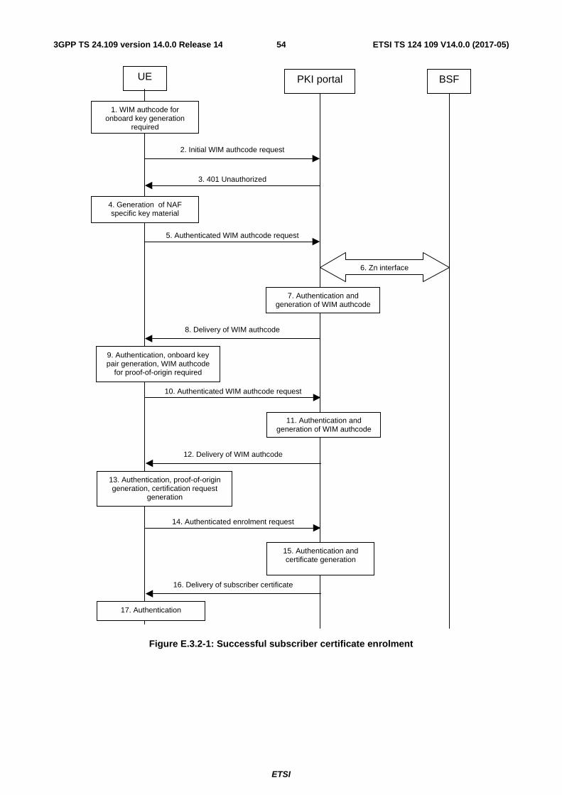
ETSI
ETSI TS 124 109 V14.0.0 (2017-05)543GPP TS 24.109 version 14.0.0 Release 14
UE PKI portal BSF
4. Generation of NAF specific key material
2. Initial WIM authcode request
3. 401 Unauthorized
5. Authenticated WIM authcode request
8. Delivery of WIM authcode
6. Zn interface
7. Authentication and generation of WIM authcode
9. Authentication, onboard key pair generation, WIM authcode
for proof-of-origin required
14. Authenticated enrolment request
16. Delivery of subscriber certificate
15. Authentication and certificate generation
17. Authentication
1. WIM authcode for onboard key generation
required
10. Authenticated WIM authcode request
12. Delivery of WIM authcode
11. Authentication and generation of WIM authcode
13. Authentication, proof-of-origin generation, certification request
generation
Figure E.3.2-1: Successful subscriber certificate enrolment
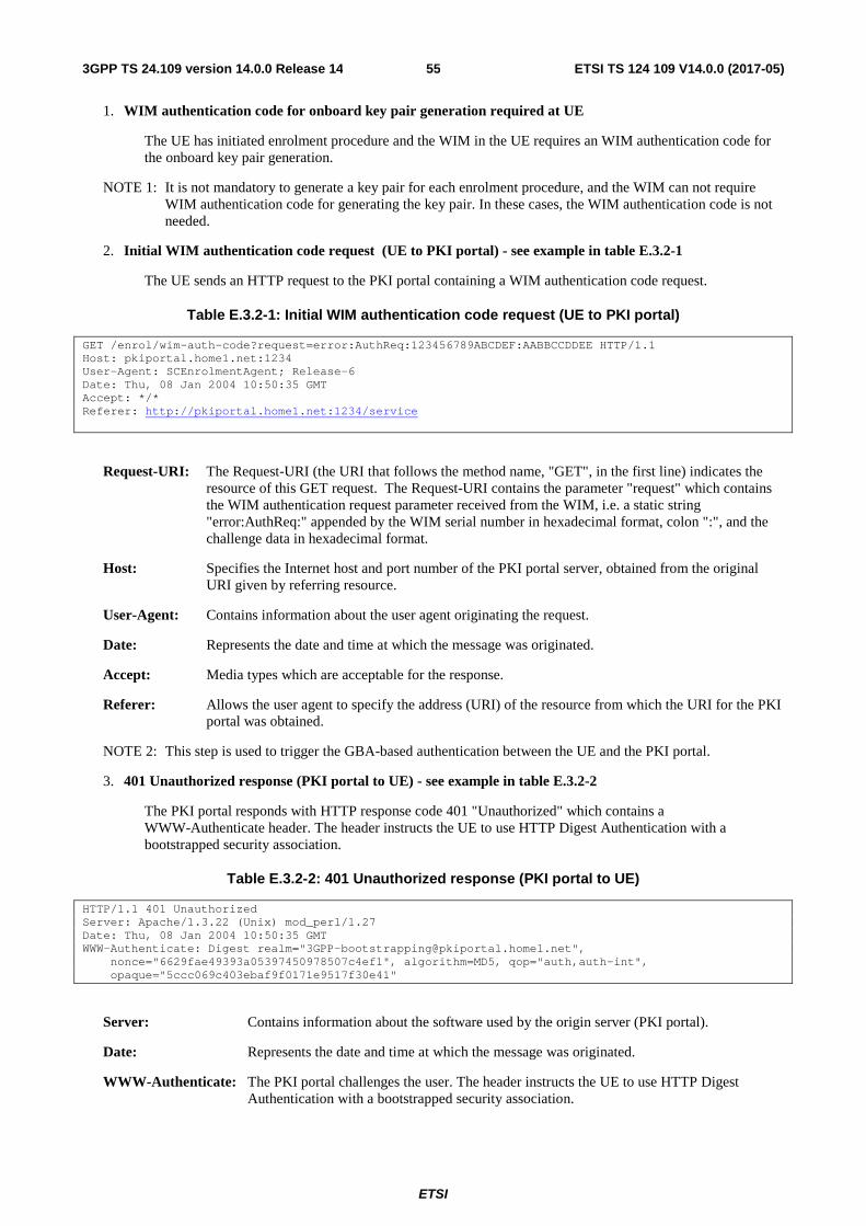
ETSI
ETSI TS 124 109 V14.0.0 (2017-05)553GPP TS 24.109 version 14.0.0 Release 14
1. WIM authentication code for onboard key pair generation required at UE
The UE has initiated enrolment procedure and the WIM in the UE requires an WIM authentication code for the onboard key pair generation.
NOTE 1: It is not mandatory to generate a key pair for each enrolment procedure, and the WIM can not require WIM authentication code for generating the key pair. In these cases, the WIM authentication code is not needed.
2. Initial WIM authentication code request (UE to PKI portal) - see example in table E.3.2-1
The UE sends an HTTP request to the PKI portal containing a WIM authentication code request.
Table E.3.2-1: Initial WIM authentication code request (UE to PKI portal)
GET /enrol/wim-auth-code?request=error:AuthReq:123456789ABCDEF:AABBCCDDEE HTTP/1.1 Host: pkiportal.home1.net:1234 User-Agent: SCEnrolmentAgent; Release-6 Date: Thu, 08 Jan 2004 10:50:35 GMT Accept: */* Referer: http://pkiportal.home1.net:1234/service
Request-URI: The Request-URI (the URI that follows the method name, "GET", in the first line) indicates the resource of this GET request. The Request-URI contains the parameter "request" which contains the WIM authentication request parameter received from the WIM, i.e. a static string "error:AuthReq:" appended by the WIM serial number in hexadecimal format, colon ":", and the challenge data in hexadecimal format.
Host: Specifies the Internet host and port number of the PKI portal server, obtained from the original URI given by referring resource.
User-Agent: Contains information about the user agent originating the request.
Date: Represents the date and time at which the message was originated.
Accept: Media types which are acceptable for the response.
Referer: Allows the user agent to specify the address (URI) of the resource from which the URI for the PKI portal was obtained.
NOTE 2: This step is used to trigger the GBA-based authentication between the UE and the PKI portal.
3. 401 Unauthorized response (PKI portal to UE) - see example in table E.3.2-2
The PKI portal responds with HTTP response code 401 "Unauthorized" which contains a WWW-Authenticate header. The header instructs the UE to use HTTP Digest Authentication with a bootstrapped security association.
Table E.3.2-2: 401 Unauthorized response (PKI portal to UE)
HTTP/1.1 401 Unauthorized Server: Apache/1.3.22 (Unix) mod_perl/1.27 Date: Thu, 08 Jan 2004 10:50:35 GMT WWW-Authenticate: Digest realm="[email protected]",
nonce="6629fae49393a05397450978507c4ef1", algorithm=MD5, qop="auth,auth-int", opaque="5ccc069c403ebaf9f0171e9517f30e41"
Server: Contains information about the software used by the origin server (PKI portal).
Date: Represents the date and time at which the message was originated.
WWW-Authenticate: The PKI portal challenges the user. The header instructs the UE to use HTTP Digest Authentication with a bootstrapped security association.
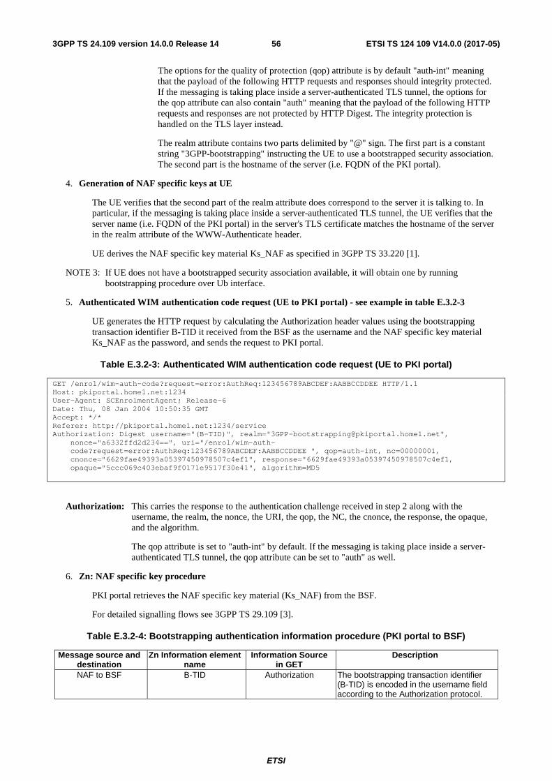
ETSI
ETSI TS 124 109 V14.0.0 (2017-05)563GPP TS 24.109 version 14.0.0 Release 14
The options for the quality of protection (qop) attribute is by default "auth-int" meaning that the payload of the following HTTP requests and responses should integrity protected. If the messaging is taking place inside a server-authenticated TLS tunnel, the options for the qop attribute can also contain "auth" meaning that the payload of the following HTTP requests and responses are not protected by HTTP Digest. The integrity protection is handled on the TLS layer instead.
The realm attribute contains two parts delimited by "@" sign. The first part is a constant string "3GPP-bootstrapping" instructing the UE to use a bootstrapped security association. The second part is the hostname of the server (i.e. FQDN of the PKI portal).
4. Generation of NAF specific keys at UE
The UE verifies that the second part of the realm attribute does correspond to the server it is talking to. In particular, if the messaging is taking place inside a server-authenticated TLS tunnel, the UE verifies that the server name (i.e. FQDN of the PKI portal) in the server's TLS certificate matches the hostname of the server in the realm attribute of the WWW-Authenticate header.
UE derives the NAF specific key material Ks_NAF as specified in 3GPP TS 33.220 [1].
NOTE 3: If UE does not have a bootstrapped security association available, it will obtain one by running bootstrapping procedure over Ub interface.
5. Authenticated WIM authentication code request (UE to PKI portal) - see example in table E.3.2-3
UE generates the HTTP request by calculating the Authorization header values using the bootstrapping transaction identifier B-TID it received from the BSF as the username and the NAF specific key material Ks_NAF as the password, and sends the request to PKI portal.
Table E.3.2-3: Authenticated WIM authentication code request (UE to PKI portal)
GET /enrol/wim-auth-code?request=error:AuthReq:123456789ABCDEF:AABBCCDDEE HTTP/1.1 Host: pkiportal.home1.net:1234 User-Agent: SCEnrolmentAgent; Release-6 Date: Thu, 08 Jan 2004 10:50:35 GMT Accept: */* Referer: http://pkiportal.home1.net:1234/service Authorization: Digest username="(B-TID)", realm="[email protected]",
nonce="a6332ffd2d234==", uri="/enrol/wim-auth-code?request=error:AuthReq:123456789ABCDEF:AABBCCDDEE ", qop=auth-int, nc=00000001, cnonce="6629fae49393a05397450978507c4ef1", response="6629fae49393a05397450978507c4ef1, opaque="5ccc069c403ebaf9f0171e9517f30e41", algorithm=MD5
Authorization: This carries the response to the authentication challenge received in step 2 along with the username, the realm, the nonce, the URI, the qop, the NC, the cnonce, the response, the opaque, and the algorithm.
The qop attribute is set to "auth-int" by default. If the messaging is taking place inside a server-authenticated TLS tunnel, the qop attribute can be set to "auth" as well.
6. Zn: NAF specific key procedure
PKI portal retrieves the NAF specific key material (Ks_NAF) from the BSF.
For detailed signalling flows see 3GPP TS 29.109 [3].
Table E.3.2-4: Bootstrapping authentication information procedure (PKI portal to BSF)
Message source and destination
Zn Information element name
Information Source in GET
Description
NAF to BSF B-TID Authorization The bootstrapping transaction identifier (B-TID) is encoded in the username field according to the Authorization protocol.

ETSI
ETSI TS 124 109 V14.0.0 (2017-05)573GPP TS 24.109 version 14.0.0 Release 14
7. Authentication and WIM authentication code generation at NAF
PKI portal verifies the Authorization header by using the bootstrapping transaction identifier B-TID and the key material Ks_NAF obtained from BSF. The PKI portal calculates the corresponding digest values using Ks_NAF, and compares the calculated values with the received values in the Authorization header.
The PKI portal also verifies that the hostname (i.e. its FQDN) in the realm attribute matches its own. If the messaging is taking place inside a server-authenticated TLS tunnel, the PKI portal also verifies that this hostname is the same as that of the TLS server.
If the verification succeeds, the WIM authentication code is taken in for further processing. The PKI portal continues processing of the WIM authentication code request according to its internal policies.
NOTE 4: The procedures for generating the WIM authentication code are outside the scope.
8. Delivery of WIM authentication code (PKI portal to UE) - see example in table E.3.2-5
The PKI portal sends 200 OK response to the UE to indicate the success of the authentication and the WIM authentication code generation. The PKI portal generates a HTTP response containing the WIM authentication code. The PKI portal can use key material Ks_NAF to integrity protect and authenticate the response.
Table E.3.2-5: Delivery of WIM authentication code (PKI portal to UE)
HTTP/1.1 200 OK Server: Apache/1.3.22 (Unix) mod_perl/1.27 Content-Type: text/plain Content-Length: (...) Authentication-Info: qop=auth-int, rspauth="6629fae49394a05397450978507c4ef1",
cnonce="6629fae49393a05397450978507c4ef1", nc=00000001 Date: Thu, 08 Jan 2004 10:50:35 GMT Expires: Fri, 09 Jan 2004 10:50:36 GMT 13579BDF2468ACE
Content-Type: Contains the media type "text/plain".
Content-Length: Indicates the size of the entity-body, in decimal number of OCTETs, sent to the recipient.
Authentication-Info: This carries the protection
Expires: Gives the date/time after which the response is considered stale.
9. Authentication, key pair generation, and WIM authentication code request for proof-of-origin generation at UE
The UE receives the response and verifies the Authentication-Info header. If the verification succeeds, the UE can use the WIM authentication code in the onboard key pair generation with the WIM.
The WIM in the UE also requires a WIM authentication code for the proof-of-origin generation.
NOTE 5: It is not mandatory to include the proof-of-origin to certificate request of the enrolment procedure, and the WIM can not require WIM authentication code for generating the proof-of-origin. In these cases, the WIM authentication code is not needed.
10. Authenticated WIM authentication code request (UE to PKI portal) - see example in table E.3.2-6
The UE generates the HTTP request by calculating the Authorization header values using the bootstrapping transaction identifier B-TID it received from the BSF as the username and the NAF specific key material Ks_NAF as the password, and sends the request to PKI portal.
Table E.3.2-6: Authenticated WIM authentication code request (UE to PKI portal)
GET /enrol/wim-auth-code?request=error:AuthReq:1122334455667788:1122334455 HTTP/1.1 Host: pkiportal.home1.net:1234 User-Agent: SCEnrolmentAgent; Release-6 Date: Thu, 08 Jan 2004 10:50:35 GMT

ETSI
ETSI TS 124 109 V14.0.0 (2017-05)583GPP TS 24.109 version 14.0.0 Release 14
Accept: */* Referer: http://pkiportal.home1.net:1234/service Authorization: Digest username="(B-TID)", realm="[email protected]",
nonce="a6332ffd2d234==", uri="/enrol/wim-auth-code?request=error:AuthReq:123456789ABCDEF:AABBCCDDEE ", qop=auth-int, nc=00000001, cnonce="6629fae49393a05397450978507c4ef1", response="6629fae49393a05397450978507c4ef1, opaque="5ccc069c403ebaf9f0171e9517f30e41", algorithm=MD5
11. Authentication and WIM authentication code generation at NAF
PKI portal verifies the Authorization header by using the bootstrapping transaction identifier B-TID and the key material Ks_NAF obtained from BSF. PKI portal calculates the corresponding digest values using Ks_NAF, and compares the calculated values with the received values in the Authorization header.
The PKI portal also verifies that the hostname (i.e. its FQDN) in the realm attribute matches its own. If the messaging is taking place inside a server-authenticated TLS tunnel, the PKI portal also verifies that this hostname is the same as that of the TLS server.
If the verification succeeds, the WIM authentication code is taken in for further processing. The PKI portal continues processing of the WIM authentication code request according to its internal policies.
NOTE 6: The procedures for generating the WIM authentication code are outside the scope.
12. Delivery of WIM authentication code (PKI portal to UE) - see example in table E.3.2-7
The PKI portal sends 200 OK response to the UE to indicate the success of the authentication and the WIM authentication code generation. The PKI portal generates a HTTP response containing the WIM authentication code. The PKI portal can use key material Ks_NAF to integrity protect and authenticate the response.
Table E.3.2-7: Delivery of WIM authentication code (PKI portal to UE)
HTTP/1.1 200 OK Server: Apache/1.3.22 (Unix) mod_perl/1.27 Content-Type: text/plain Content-Length: (...) Authentication-Info: qop=auth-int, rspauth="6629fae49394a05397450978507c4ef1",
cnonce="6629fae49393a05397450978507c4ef1", nc=00000001 Date: Thu, 08 Jan 2004 10:50:35 GMT Expires: Fri, 09 Jan 2004 10:50:36 GMT FFEEDDCCBBAA998877665544
Content-Type: Contains the media type "text/plain".
Content-Length: Indicates the size of the entity-body, in decimal number of OCTETs, sent to the recipient.
Authentication-Info: This carries the protection
Expires: Gives the date/time after which the response is considered stale.
13. Authentication, proof-key-origin key pair generation, and PKCS#10 generation at UE
The UE receives the response and verifies the Authentication-Info header. If the verification succeeds, the UE can use the WIM authentication code in the proof-of-origin generation with the WIM.
The WIM in the UE also requires a WIM authentication code for the proof-of-origin generation.
NOTE 7: It is not mandatory to include the proof-of-origin to certificate request of the enrolment procedure, and the WIM can not require WIM authentication code for generating the proof-of-origin. In these cases, the WIM authentication code is not needed.
14. Authenticated enrolment request (UE to PKI portal) - see example in table E.3.2-8

ETSI
ETSI TS 124 109 V14.0.0 (2017-05)593GPP TS 24.109 version 14.0.0 Release 14
UE generates the HTTP request by calculating the Authorization header values using the bootstrapping transaction identifier B-TID it received from the BSF as the username and the NAF specific key material Ks_NAF as the password, and sends the request to PKI portal.
Table E.3.2-8: Authenticated enrolment request (UE to PKI portal)
POST /enrol?response=single HTTP/1.1 Host: pkiportal.home1.net:1234 Content-Type: application/pkcs10 Content-Length: (...) User-Agent: SCEnrolmentAgent; Release-6 Date: Thu, 08 Jan 2004 10:50:35 GMT Accept: */* Referer: http://pkiportal.home1.net:1234/service Authorization: Digest username="(B-TID)", realm="[email protected]",
nonce="a6332ffd2d234==", uri="/enrol?response=single", qop=auth-int, nc=00000002, cnonce="6629fae49393a05397450978507c4ef1", response="6629fae49393a05397450978507c4ef1, opaque="5ccc069c403ebaf9f0171e9517f30e41", algorithm=MD5
----- BEGIN CERTIFICATE REQUEST ----- <PKCS#10 BLOB> ----- END CERTIFICATE REQUEST -----
Authorization: This carries the response to the authentication challenge received in step 2 along with the username, the realm, the nonce, the URI, the qop, the NC, the cnonce, the response, the opaque, and the algorithm.
The qop attribute is set to "auth-int" by default. If the messaging is taking place inside a server-authenticated TLS tunnel, the qop attribute can be set to "auth" as well.
15. Authentication and certificate generation at PKI portal
PKI portal verifies the Authorization header by using the bootstrapping transaction identifier B-TID and the key material Ks_NAF obtained from BSF. PKI portal calculates the corresponding digest values using Ks_NAF, and compares the calculated values with the received values in the Authorization header.
The PKI portal also verifies that the hostname (i.e. its FQDN) in the realm attribute matches its own. If the messaging is taking place inside a server-authenticated TLS tunnel, the PKI portal also verifies that this hostname is the same as that of the TLS server.
If the verification succeeds, the incoming client-payload request is taken in for further processing. The PKI portal continues processing of the PKCS#10 request according to its internal policies.
NOTE 8: The procedures for generating the subscriber certificate are outside the scope.
16. Delivery of subscriber certificate (PKI portal to UE) - see example in table E.3.2-9
The PKI portal sends 200 OK response to the UE to indicate the success of the authentication and the subscriber certificate enrolment. The PKI portal generates a HTTP response containing the enrolled subscriber certificate. The PKI portal can use key material Ks_NAF to integrity protect and authenticate the response.
Table E.3.2-9: Delivery of subscriber certificate (PKI portal to UE)
HTTP/1.1 200 OK Server: Apache/1.3.22 (Unix) mod_perl/1.27 Content-Type: text/html Content-Type: application/x-x509-user-cert Content-Length: (...) Authentication-Info: qop=auth-int, rspauth="6629fae49394a05397450978507c4ef1",
cnonce="6629fae49393a05397450978507c4ef1", nc=00000001 Date: Thu, 08 Jan 2004 10:50:35 GMT Expires: Fri, 09 Jan 2004 10:50:36 GMT ----- BEGIN CERTIFICATE ----- <Subscriber certificate BLOB> ----- END CERTIFICATE -----

ETSI
ETSI TS 124 109 V14.0.0 (2017-05)603GPP TS 24.109 version 14.0.0 Release 14
Content-Type: Contains the media type "application/x-x509-user-cert", i.e. X.509 certificate.
Content-Length: Indicates the size of the entity-body, in decimal number of OCTETs, sent to the recipient.
Authentication-Info: This carries the protection
Expires: Gives the date/time after which the response is considered stale.
17. Authentication at UE
The UE receives the response and verifies the Authentication-Info header. If the verification succeeds, the UE can accept the subscriber certificate for further processing.
E.4 Signalling flows demonstrating a failure in subscriber certificate enrolment
The signalling flow in figure E.3.1-1 describes the message exchange between UE and PKI portal using HTTP Digest Authentication. This clause describes a failure in the subscriber certificate enrolment, related to PKI procedures. Thus, it assumed that subscriber certificate enrolment procedure has proceeded to step 6 as described in subclause E.3.1.
6. Authentication and certificate generation at PKI portal
The verification procedures described in subclause E.3.1 step 6 are successfully completed.
The PKI portal encounters an error during the internal enrolment procedure. For example, the PKI portal is not allowed to issue a certificate to the subscriber due operator's internal policies, i.e. the subscriber's profile in the HSS indicates that the enrolment is not allowed.
7. Error notification (PKI portal to UE) - see example in table E.4-1
The PKI portal sends 403 Forbidden response to the UE to indicate that the subscriber certificate enrolment is allowed. The PKI portal generates a HTTP response containing the error notification. The PKI portal can use key material Ks_NAF to authenticate the response.
Table E.4-1: Error notification (PKI portal to UE)
HTTP/1.1 403 Forbidden Server: Apache/1.3.22 (Unix) mod_perl/1.27 Content-Type: text/html Authentication-Info: qop=auth-int, rspauth="6629fae49394a05397450978507c4ef1", cnonce="6629fae49393a05397450978507c4ef1", nc=00000001 Date: Thu, 08 Jan 2004 10:50:35 GMT Expires: Fri, 09 Jan 2004 10:50:36 GMT
Authentication-Info: This carries the protection
Expires: Gives the date/time after which the response is considered stale.
8. Authentication at UE
The UE receives the response and verifies the Authentication-Info header. If the verification succeeds, the UE is notified of the failure of the subscriber certificate enrolment.
E.5 Signalling flows demonstrating a successful CA certificate delivery
The signalling flow in figure E.5-1 describes the message exchange between UE and PKI portal when UE requests a CA certificate delivery. The messaging can take place inside a server-authenticated TLS (as described in the RFC for TLS defined in annex E of 3GPP TS 33.310 [25]) tunnel in which case TLS session has been established before step 1.

ETSI
ETSI TS 124 109 V14.0.0 (2017-05)613GPP TS 24.109 version 14.0.0 Release 14
UE PKI portal BSF
3. Generation of NAF specific key material
1. Initial get request
2. 401 Unauthorized
4. Authenticated get request
7. Delivery of CA certificate
5. Zn interface
6. Authentication
8. Authentication and response verification
Figure E.5-1: Successful CA certificate delivery.
1. Initial get request (UE to PKI portal) - see example in table E.5-1
The UE sends an HTTP request to the PKI portal requesting the delivery of CA certificate.
Table E.5-1: Initial get request (UE to PKI portal)
GET /getcertificate?in=aabbccdd== HTTP/1.1 Host: pkiportal.home1.net:1234 User-Agent: SCEnrolmentAgent; Release-6 Date: Thu, 08 Jan 2004 10:50:35 GMT Accept: */* Referer: http://pkiportal.home1.net:1234/service
Request-URI: The Request-URI (the URI that follows the method name, "GET", in the first line) indicates the resource indication of this GET request. The Request-URI contains the parameter "in" (i.e. issuer name) which is set to the Base64 encoding of the DER encoded Issuer field of the X.509 certificate.
Host: Specifies the Internet host and port number of the PKI portal server, obtained from the original URI given by referring resource.
User-Agent: Contains information about the user agent originating the request.
Date: Represents the date and time at which the message was originated.
Accept: Media types which are acceptable for the response.
Referer: Allows the user agent to specify the address (URI) of the resource from which the URI for the PKI portal was obtained.
NOTE 1: This step is used to trigger the GBA-based authentication between the UE and the PKI portal.

ETSI
ETSI TS 124 109 V14.0.0 (2017-05)623GPP TS 24.109 version 14.0.0 Release 14
2. 401 Unauthorized response (PKI portal to UE) - see example in table E.5-2
The PKI portal responds with HTTP response code 401 "Unauthorized" which contains a WWW-Authenticate header. The header instructs the UE to use HTTP Digest Authentication with a bootstrapped security association.
Table E.5-2: 401 Unauthorized response (PKI portal to UE)
HTTP/1.1 401 Unauthorized Server: Apache/1.3.22 (Unix) mod_perl/1.27 Date: Thu, 08 Jan 2004 10:50:35 GMT WWW-Authenticate: Digest realm="[email protected]",
nonce="6629fae49393a05397450978507c4ef1", algorithm=MD5, qop="auth,auth-int", opaque="5ccc069c403ebaf9f0171e9517f30e41"
Server: Contains information about the software used by the origin server (PKI portal).
Date: Represents the date and time at which the message was originated.
WWW-Authenticate: The PKI portal challenges the user. The header instructs the UE to use HTTP Digest Authentication with a bootstrapped security association.
The options for the quality of protection (qop) attribute is by default "auth-int" meaning that the payload of the following HTTP requests and responses should integrity protected. If the messaging is taking place inside a server-authenticated TLS tunnel, the options for the qop attribute can also contain "auth" meaning that the payload of the following HTTP requests and responses are not protected by HTTP Digest. The integrity protection is handled on the TLS layer instead.
The realm attribute contains two parts delimited by "@" sign. The first part is a constant string "3GPP-bootstrapping" instructing the UE to use a bootstrapped security association. The second part is the host of the server (i.e. the FQDN of the PKI portal).
3. Generation of NAF specific keys at UE
The UE verifies that the second part of the realm attribute does correspond to the server it is talking to. In particular, if the messaging is taking place inside a server-authenticated TLS tunnel, the UE verifies that the server name (i.e. FQDN of the PKI portal) in the server's TLS certificate matches the hostname of the server in the realm attribute of the WWW-Authenticate header.
UE derives the NAF specific key material Ks_NAF as specified in 3GPP TS 33.220 [1].
NOTE 2: If UE does not have a bootstrapped security association available, it will obtain one by running bootstrapping procedure over Ub interface.
4. Authenticated get request (UE to PKI portal) - see example in table E.5-3
UE generates the HTTP request by calculating the Authorization header values using the bootstrapping transaction identifier B-TID it received from the BSF as the username and the NAF specific key material Ks_NAF (base64 encoded) as the password, and sends the request to PKI portal.
Table E.5-3: Authenticated get request (UE to PKI portal)
GET /getcertificate?in=aabbccdd== HTTP/1.1 Host: pkiportal.home1.net:1234 User-Agent: SCEnrolmentAgent; Release-6 Date: Thu, 08 Jan 2004 10:50:35 GMT Accept: */* Referer: http://pkiportal.home1.net:1234/service Authorization: Digest username="(B-TID)", realm="[email protected]",
nonce="a6332ffd2d234==", uri="/getcertificate?in=aabbccdd==", qop=auth-int, nc=00000001, cnonce="6629fae49393a05397450978507c4ef1", response="6629fae49393a05397450978507c4ef1", opaque="5ccc069c403ebaf9f0171e9517f30e41", algorithm=MD5

ETSI
ETSI TS 124 109 V14.0.0 (2017-05)633GPP TS 24.109 version 14.0.0 Release 14
Authorization: This carries the response to the authentication challenge received in step 2 along with the username, the realm, the nonce, the URI, the qop, the NC, the cnonce, the response, the opaque, and the algorithm.
The qop attribute is set to "auth-int" by default. If the messaging is taking place inside a server-authenticated TLS tunnel, the qop attribute can be set to "auth" as well.
NOTE 3: If step 1 was a GET request then this request would also be GET request and contain the same Request-URI in the HTTP request as was carried in step 1.
5. Zn: NAF specific key procedure
PKI portal retrieves the NAF specific key material (Ks_NAF) from the BSF.
For detailed signalling flows see 3GPP TS 29.109 [3].
Table E.5-4: Bootstrapping authentication information procedure (PKI portal to BSF)
Message source and destination
Zn Information element name
Information Source in GET
Description
NAF to BSF B-TID Authorization The bootstrapping transaction identifier (B-TID) is encoded in the username field according to the Authorization protocol.
6. Authentication at PKI portal
PKI portal verifies the Authorization header by using the bootstrapping transaction identifier B-TID and the key material Ks_NAF obtained from BSF. PKI portal calculates the corresponding digest values using Ks_NAF, and compares the calculated values with the received values in the Authorization header.
The PKI portal also verifies that the hostname (i.e. its FQDN) in the realm attribute matches its own. If the HTTP messaging is taking place inside a server-authenticated TLS tunnel, the PKI portal also verifies that this hostname is the same as that of the TLS server.
If the verification succeeds, the incoming client-payload request is taken in for further processing, i.e. the PKI portal sends the requested CA certificate to the UE.
7. Delivery of CA certificate (PKI portal to UE) – see example in table E.5-5
The PKI portal sends 200 OK response to the UE to indicate the success of the authentication. The PKI portal generates a HTTP response containing the requested CA certificate. The PKI portal use the key material Ks_NAF to integrity protect and authenticate the response.
Table E.5-5: Delivery of CA certificate (PKI portal to UE)
HTTP/1.1 200 OK Server: Apache/1.3.22 (Unix) mod_perl/1.27 Content-Type: text/html Content-Type: application/x-x509-ca-cert Content-Length: (...) Authentication-Info: qop=auth-int, rspauth="6629fae49394a05397450978507c4ef1",
cnonce="6629fae49393a05397450978507c4ef1", nc=00000001 Date: Thu, 08 Jan 2004 10:50:35 GMT Expires: Fri, 09 Jan 2004 10:50:36 GMT ----- BEGIN CERTIFICATE ----- <CA certificate BLOB> ----- END CERTIFICATE -----
Content-Type: Contains the media type "application/x-x509-ca-cert", i.e. X.509 CA certificate.
Content-Length: Indicates the size of the entity-body, in decimal number of OCTETs, sent to the recipient.
Authentication-Info: This carries the protection.
Expires: Gives the date/time after which the response is considered stale.
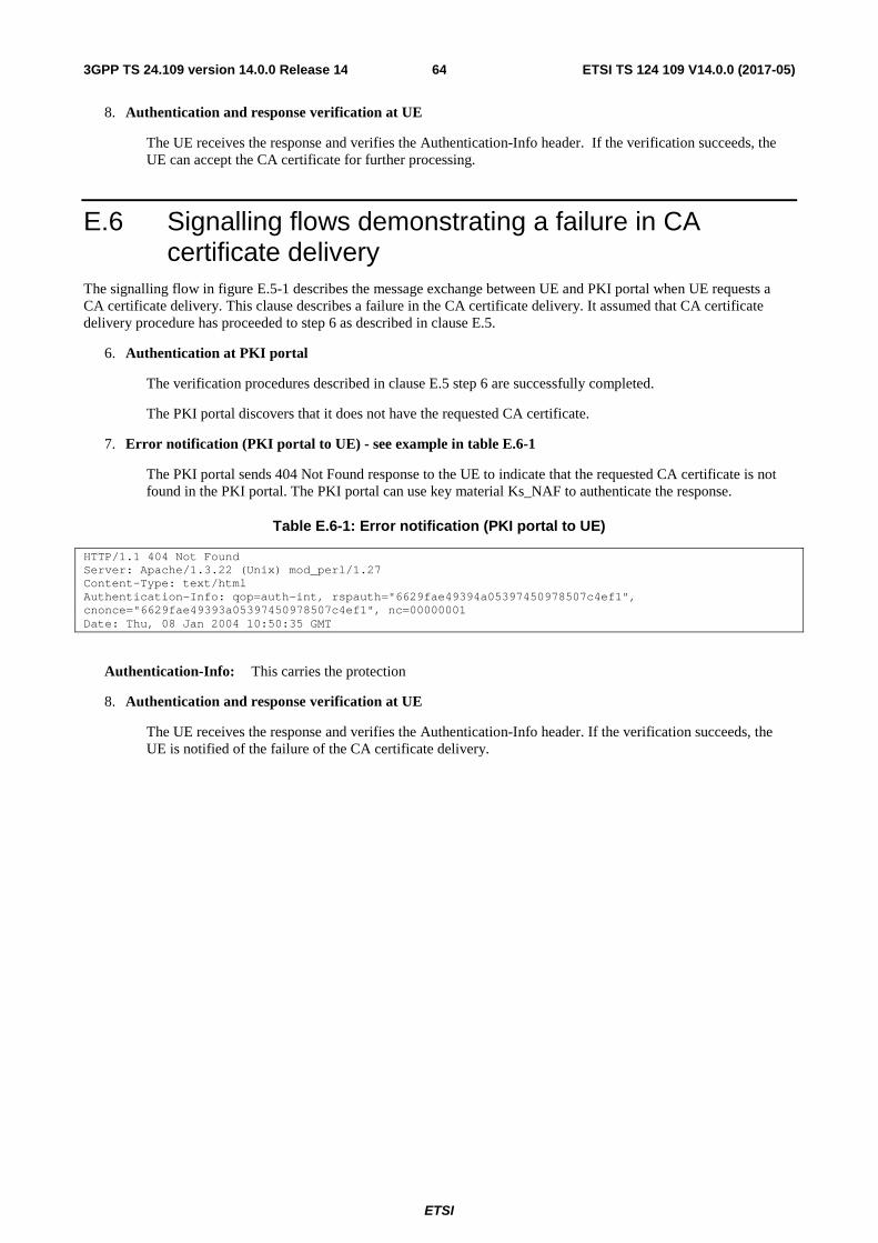
ETSI
ETSI TS 124 109 V14.0.0 (2017-05)643GPP TS 24.109 version 14.0.0 Release 14
8. Authentication and response verification at UE
The UE receives the response and verifies the Authentication-Info header. If the verification succeeds, the UE can accept the CA certificate for further processing.
E.6 Signalling flows demonstrating a failure in CA certificate delivery
The signalling flow in figure E.5-1 describes the message exchange between UE and PKI portal when UE requests a CA certificate delivery. This clause describes a failure in the CA certificate delivery. It assumed that CA certificate delivery procedure has proceeded to step 6 as described in clause E.5.
6. Authentication at PKI portal
The verification procedures described in clause E.5 step 6 are successfully completed.
The PKI portal discovers that it does not have the requested CA certificate.
7. Error notification (PKI portal to UE) - see example in table E.6-1
The PKI portal sends 404 Not Found response to the UE to indicate that the requested CA certificate is not found in the PKI portal. The PKI portal can use key material Ks_NAF to authenticate the response.
Table E.6-1: Error notification (PKI portal to UE)
HTTP/1.1 404 Not Found Server: Apache/1.3.22 (Unix) mod_perl/1.27 Content-Type: text/html Authentication-Info: qop=auth-int, rspauth="6629fae49394a05397450978507c4ef1", cnonce="6629fae49393a05397450978507c4ef1", nc=00000001 Date: Thu, 08 Jan 2004 10:50:35 GMT
Authentication-Info: This carries the protection
8. Authentication and response verification at UE
The UE receives the response and verifies the Authentication-Info header. If the verification succeeds, the UE is notified of the failure of the CA certificate delivery.
ETSI
ETSI TS 124 109 V14.0.0 (2017-05)653GPP TS 24.109 version 14.0.0 Release 14
Annex F (informative): Signalling flows for PSK TLS with bootstrapped security association
F.1 Scope of signalling flows This annex gives examples of signalling flows for using PSK TLS with bootstrapped security association.
F.2 Introduction
F.2.1 General A bootstrapping session established using a bootstrapping procedure (cf., clause 4 and annex A) is used between a UE and a NAF. The BSF provides to the NAF a NAF specific key material (Ks_NAF or Ks_ext_NAF and optionally Ks_int_NAF) which is derived from the key material (Ks). The NAF uses this key to authenticate and optionally secure (i.e. integrity protect and encrypt) the communications between it and the UE. The BSF will also provide the NAF the expiration time of the bootstrapping session. When the bootstrapping session becomes invalid the NAF will stop using the session, and indicate to the UE that bootstrapping session has expired and that new session needs to be established.
An example of the signalling flows of the authentication procedure using PSK TLS is given in clause F.3.
F.2.2 Key required to interpret signalling flows The following key (rules) have been applied to TLS handshake signalling flows to improve readability, reduce errors and increase maintainability:
a) The description of TLS messages and their fields are identified by three fields: "TLS.MESSAGE.FIELD":
- "TLS" identifies that the message is a TLS message;
- "MESSAGE" identifies the name of the TLS message (e.g. ClientHello);
- "FIELD" identifies the name of the TLS message field (e.g. client_version).
An example being "TLS.ClientHello.client_version", which identifies TLS message "ClientHello" and its data field "client_version". The possible TLS message and TLS message field names as well as their encoding to the TLS protocol are specified in IETF TLS related specifications as defined in annex E of 3GPP TS 33.310 [25].
b) If multiple TLS messages are sent in sequence from one entity to another this is described as one step.
- the figures describe the sending of multiple TLS messages in one step by listing the TLS message names in separate lines;
- the description of the step contains the explanation of the messages and their parameters as described in bullet a).
c) In order to differentiate between TLS messages and other protocol messages, the TLS messages are marked with simple arrow line, and all non-TLS messages with block arrows.
d) The flows show the signalling exchanges between the following functional entities:
- User Equipment (UE);
- Bootstrapping Server Function (BSF);
- Network Application Function (NAF).

ETSI
ETSI TS 124 109 V14.0.0 (2017-05)663GPP TS 24.109 version 14.0.0 Release 14
F.3 Signalling flow demonstrating a successful PSK TLS authentication procedure
The signalling flow in figure F.3-1 describes the generic message exchange between UE and NAF using PSK TLS. In this example, the PSK TLS client application resides in the ME, i.e., either Ks_NAF or Ks_ext_NAF is used as the key.
UE BSF
ClientHello(PSK-based ciphersuites)
ServerHello(PSK-based ciphersuite)ServerKeyExchange(PSK identity hint)
ServerHelloDone
Application Data
NAF
(5) Zn interface
(3) Bootstrapping and generation of NAF specific key material
ClientKeyExchange(PSK identity) ChangeCipherSpec Finished
ChangeCipherSpecFinished
(1)
(2)
(4)
(7)
(9)
(6) Authentication
(8) Authentication
Figure F.3-1: PSK TLS handshake with bootstrapped security association.
1. TLS handshake message: ClientHello (UE to NAF)
The UE sends ClientHello message to the NAF. In order to indicate that the UE is capable of PSK-based authentication it includes the PSK-based ciphersuites to the list of acceptable ciphersuites list. The UE also includes to the ClientHello message the server_name TLS extension containing the hostname of the NAF.
TLS.ClientHello.client_version: the version of the TLS protocol in the UE is 3.1.
TLS.ClientHello.random: a UE generated random structure.
TLS.ClientHello.session_id: the ID of the TLS session is empty, i.e. no previous TLS session is used.
TLS.ClientHello.cipher_suites: the list of ciphersuites includes one or more PSK-based ciphersuites.
TLS.ClientHello.compression_methods: a list of the compression methods is null.
TLS.ClientHello.client_hello_extension_list: list of extensions includes server_name extension that contains the hostname of the NAF.
2. TLS handshake messages: ServerHello, ServerKeyExchange, ServerHelloDone (NAF to UE)

ETSI
ETSI TS 124 109 V14.0.0 (2017-05)673GPP TS 24.109 version 14.0.0 Release 14
If the NAF wants to use PSK-based authentication, it selects one of the acceptable PSK-based ciphersuites, places the selected ciphersuite in the ServerHello message, and includes an appropriate ServerKeyExchange message. The NAF can help the UE in selecting the correct PSK identity by providing a list of hints in ServerKeyExchange message. That list includes a static string "3GPP-bootstrapping ".
TLS.ServerHello.server_version: the version of the TLS protocol in the NAF is 3.1.
TLS.ServerHello.random: a NAF generated random (must be different from ClientHello.random).
TLS.ServerHello.session_id: the identity of the TLS session generated by the NAF.
TLS.ServerHello.cipher_suite: the ciphersuite selected by the NAF is one of the PSK-based ciphersuites listed in ClientHello.cipher_suites.
TLS.ServerHello.compression_method: the compression method selected by the NAF is null.
TLS.ServerHello.server_hello_extension_list: list of extensions is empty.
TLS.ServerKeyExchange.psk_identity_hint: the PSK identity hint contains the constant string "3GPP-bootstrapping".
TLS.ServerHelloDone: this message does not have data fields.
3. Bootstrapping and generation of NAF specific key material at UE
The UE performs the bootstrapping procedure to produce B-TID and Ks_(ext)_NAF as described in clause A.3. If bootstrapping procedure has been done recently, the UE can use the B-TID and Ks_(ext)_NAF produced from that procedure.
4. TLS handshake messages: ClientKeyExchange, ChangeCipherSpec, Finished (UE to NAF)
The UE sets concatenated "3GPP-bootstrapping" string, separator character ";" and the B-TID as the PSK identity, and Ks_(ext)_NAF as the pre-shared key. The UE then sends ClientKeyExchange containing the B-TID, ChangeCipherSpec, and Finished messages to the NAF. The TLS premaster secret is derived from Ks_(ext)_NAF.
TLS.ClientKeyExchange.psk_identity: the PSK identity contains concatenated "3GPP-bootstrapping" string, separator character ";" and the B-TID.
TLS.ChangeCipherSpec.type: contains value 1 (change_cipher_spec).
TLS.Finished.verify_data: the verify data contains the hash of the handshake messages. For details, see the RFC for TLS defined in annex E of 3GPP TS 33.310 [25].
5. Zn: NAF specific key procedure
The NAF extracts the B-TID from the ClientKeyExchange message and requests the NAF specific key (Ks_NAF or Ks_ext_NAF) from BSF. The BSF returns the NAF specific key that corresponds to the B-TID.
If the NAF retrieved an application-specific USS and it contained a keyChoice indication, the NAF must enforce this indication. Hence, if the UICC-based key was indicated the NAF must terminate the communication with the UE in this phase.
NOTE: If the local configuration in the NAF restricts the access to this NAF service to UICC-based applications, then the NAF will terminate the communication with the UE in this phase.
For detailed signalling flows see 3GPP TS 29.109 [3].
Table F.3-1: Bootstrapping authentication information procedure (NAF to BSF)
Message source and destination
Zn Information element name
Information Source in TLS
Description
NAF to BSF B-TID ClientKeyExchange.psk_identity
The bootstrapping transaction identifier (B-TID) is encoded in the ClientKeyExchange.psk_identity field according to PSK TLS.

ETSI
ETSI TS 124 109 V14.0.0 (2017-05)683GPP TS 24.109 version 14.0.0 Release 14
6. Authentication at NAF
The NAF validates the Finished message sent by the UE.
7. TLS handshake messages: ChangeCipherSpec, Finished (NAF to UE)
The NAF sends ChangeCipherSpec, and Finished messages to the UE.
TLS.ChangeCipherSpec.type: contains value 1 (change_cipher_spec).
TLS.Finished.verify_data: the verify data contains the hash of the handshake messages. For details, see the RFC for TLS defined in annex E of 3GPP TS 33.310 [25].
8. Authentication at UE
The UE validates the Finished message sent by the NAF.
9. Application data transfer
The UE and the NAF initiate application data transfer in the TLS session.

ETSI
ETSI TS 124 109 V14.0.0 (2017-05)693GPP TS 24.109 version 14.0.0 Release 14
Annex G (normative): 3GPP specific extension-headers for HTTP entity-header fields
G.1 General This annex defines the syntax of 3GPP specific extension-headers introduced in this document in augmented Backus-Naur form as defined in RFC 2234 [22].
G.2 X-3GPP-Intended-Identity extension-header The "X-3GPP-Intended-Identity" header is used optionally by the UE to indicate the user identity intended to be used with the AS. It contains the user identity surrounded by quotation marks (").
Table G.2: Syntax of X-3GPP-Intended-Identity extension-header
X-3GPP-Intended-Identity = "X-3GPP-Intended-Identity" ":" DQUOTE identity DQUOTE identity = *(%x20-21 / %x23-7E)
In the syntax definition the rule 'identity' refers to the user identity and it is defined as a string of printable characters and spaces but excluding quotation marks. The exact type definition for 'identity' is done in TS 29.109 [3] as part of the User Security Setting definition (as the uid tag in the XML scheme definition).
G.3 X-3GPP-Asserted-Identity extension-header Depending on the subscriber's GBA user security settings the "X-3GPP-Asserted-Identity" header is used by the AP to indicate an asserted identity or a list of identities to the AS. It contains a list of identities separated by comma (,) and each identity is surrounded by quotation marks (").
Table G.3: Syntax of X-3GPP-Asserted-Identity extension-header
X-3GPP-Asserted-Identity = "X-3GPP-Asserted-Identity" ":" identity-list identity-list = DQUOTE identity DQUOTE *("," DQUOTE identity DQUOTE) identity = *(%x20-21 / %x23-7E)
In the syntax definition the rule 'identity' refers to the user identity and it is defined as a string of printable characters and spaces but excluding quotation marks. The exact type definition for 'identity' is done in TS 29.109 [3] as part of the User Security Setting definition (as the uid tag in the XML scheme definition).
G.4 X-3GPP-Authorization-Flags extension-header The "X-3GPP-Authorization-Flags" header is used optionally by the AP to indicate an authorization flag or a list of authorization flags from the application specific user security setting (USS) to the AS. It contains a list of authorization flags separated by comma (,) and each authorization flag is surrounded by quotation marks (").

ETSI
ETSI TS 124 109 V14.0.0 (2017-05)703GPP TS 24.109 version 14.0.0 Release 14
Table G.4: Syntax of X-3GPP-Authorization-Flags extension-header
X-3GPP-Authorization-Flags = "X-3GPP-Authorization-Flags" ":" auth-flag-list auth-flag-list = DQUOTE auth-flag DQUOTE *("," DQUOTE auth-flag DQUOTE) auth-flag = *(%x20-21 / %x23-7E)
In the syntax definition the rule 'auth-flag' refers to the authorization flag and it is defined as a string of printable characters and spaces but excluding quotation marks. The exact type definition for authorization flag is done in TS 29.109 [3] as part of the User Security Setting definition.
ETSI
ETSI TS 124 109 V14.0.0 (2017-05)713GPP TS 24.109 version 14.0.0 Release 14
Annex H (normative): 2G GBA
H.1 Introduction This annex specifies the implementation option to allow the use of SIM cards or SIMs on UICC for GBA. The procedure specified in this annex is called 2G GBA. 2G GBA allows access to applications in a more secure way that would be possible with the use of password or with GSM without enhancements. Stage 2 level details for 2G GBA has been specified in 3GPP TS 33.220 [1], Annex I.
H.2 2G GBA bootstrapping procedure A UE and the BSF shall establish a bootstrapped security association between them by running the 2G GBA bootstrapping procedure. The bootstrapping security association consists of a bootstrapping transaction identifier (B-TID) and key material Ks. Bootstrapping session on the BSF also includes security related information about subscriber (e.g. user's private identity). Bootstrapping session is valid for a certain time period, and shall be deleted in the BSF when the session becomes invalid.
It shall be possible that the BSF is configured to either allow or disallow the use of 2G GBA bootstrapping. If 2G GBA is disallowed, the BSF shall not start the TLS handshake with the UE as described below.
The 2G GBA Bootstrapping procedure as specified in 3GPP TS 33.220 [1] is further detailed as described below.
- Authorization, WWW-Authenticate, and Authentication-Info HTTP headers shall be used as described in RFC 3310 [6] with following exceptions:
a) the "realm" parameter shall contain the FQDN of the BSF. The UE shall check that the "realm" attribute contains the same FQDN of the BSF that was present in the BSF certificate.
b) the quality of protection ("qop") parameter shall be "auth-int".
c) the "username" parameter shall contain user's private identity (IMPI) which has been derived from the IMSI of the SIM application as specified in 3GPP TS 23.003 [7].
d) the "nonce" field shall be populated as specified in 3GPP TS 33.220 [1], Annex H with
- the "RAND" which is the RAND of the 2G authentication vector, and
- the "AUTN" which is a 128-bit zero number, and
- the "server specific" data is a 128-bit random number "Ks-input" generated by the BSF.
- the "RES" which is used as the password is derived as specified in 3GPP TS 33.220 [1], Annex H.
In addition to RFC 3310 [6], the following apply:
a) In the initial request from the UE to the BSF, the UE shall include Authorization header with following parameters:
- the username directive, set to the value of the private user identity IMPI derived from the IMSI of the SIM according to 3GPP TS 23.003 [7];
- the realm directive, set to the BSF address derived from the IMSI of the SIM according to 3GPP TS 23.003 [7];
- the uri directive, set to either absoluteURL "https://<BSF address>/" or abs_path "/", and which one is used is specified in RFC 2617 [9];
- the nonce directive, set to an empty value; and
- the response directive, set to an empty value;

ETSI
ETSI TS 124 109 V14.0.0 (2017-05)723GPP TS 24.109 version 14.0.0 Release 14
b) In the challenge response from the BSF to the UE, the BSF shall include parameters to WWW-Authenticate header as specified in RFC 3310 [6] with following clarifications:
- the realm directive, set to the BSF address derived from the IMSI of the SIM according to 3GPP TS 23.003 [7];
c) In the message from the BSF to the UE, the BSF shall include bootstrapping transaction identifier (B-TID) and the key lifetime to an XML document in the HTTP response payload. The BSF may also include additional server specific data to the XML document. The XML schema definition of this XML document is given in Annex C.
d) Authentication-Info header shall be included into the subsequent HTTP response after the BSF concluded that the UE has been authenticated. Authentication-Info header shall include the "rspauth" parameter.
After successful bootstrapping procedure the UE and the BSF shall contain the key material (Ks) and the B-TID. The key material shall be derived from AKA parameters as specified for 2G GBA in 3GPP TS 33.220 [1]. In addition, BSF shall also contain a set of security specific attributes (GUSS) related to the UE.
H.3 User authentication failure If the response returned by the UE is different than expected, the BSF may challenge the UE again with a new AKA challenge using a new 2G authentication vector. After N consecutive incorrect responses from the UE, the BSF shall indicate a failure to the UE. The exact value of N is defined by local policy.
H.4 Network authentication failure In case the UE fails at authenticating the network, the UE shall abort the bootstrapping procedure.
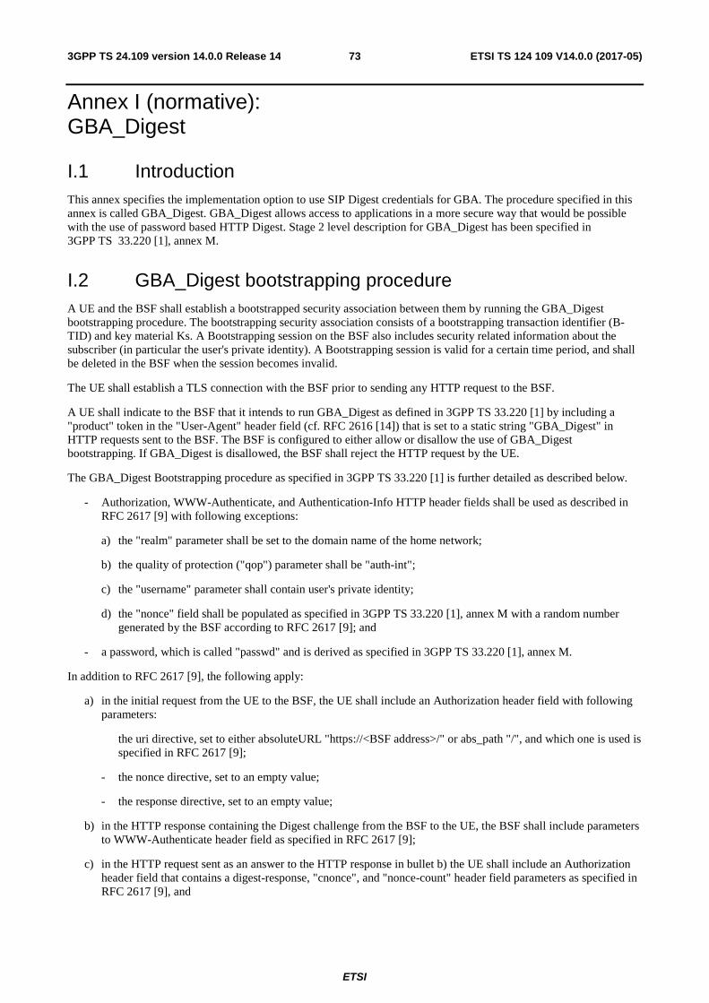
ETSI
ETSI TS 124 109 V14.0.0 (2017-05)733GPP TS 24.109 version 14.0.0 Release 14
Annex I (normative): GBA_Digest
I.1 Introduction This annex specifies the implementation option to use SIP Digest credentials for GBA. The procedure specified in this annex is called GBA_Digest. GBA_Digest allows access to applications in a more secure way that would be possible with the use of password based HTTP Digest. Stage 2 level description for GBA_Digest has been specified in 3GPP TS 33.220 [1], annex M.
I.2 GBA_Digest bootstrapping procedure A UE and the BSF shall establish a bootstrapped security association between them by running the GBA_Digest bootstrapping procedure. The bootstrapping security association consists of a bootstrapping transaction identifier (B-TID) and key material Ks. A Bootstrapping session on the BSF also includes security related information about the subscriber (in particular the user's private identity). A Bootstrapping session is valid for a certain time period, and shall be deleted in the BSF when the session becomes invalid.
The UE shall establish a TLS connection with the BSF prior to sending any HTTP request to the BSF.
A UE shall indicate to the BSF that it intends to run GBA_Digest as defined in 3GPP TS 33.220 [1] by including a "product" token in the "User-Agent" header field (cf. RFC 2616 [14]) that is set to a static string "GBA_Digest" in HTTP requests sent to the BSF. The BSF is configured to either allow or disallow the use of GBA_Digest bootstrapping. If GBA_Digest is disallowed, the BSF shall reject the HTTP request by the UE.
The GBA_Digest Bootstrapping procedure as specified in 3GPP TS 33.220 [1] is further detailed as described below.
- Authorization, WWW-Authenticate, and Authentication-Info HTTP header fields shall be used as described in RFC 2617 [9] with following exceptions:
a) the "realm" parameter shall be set to the domain name of the home network;
b) the quality of protection ("qop") parameter shall be "auth-int";
c) the "username" parameter shall contain user's private identity;
d) the "nonce" field shall be populated as specified in 3GPP TS 33.220 [1], annex M with a random number generated by the BSF according to RFC 2617 [9]; and
- a password, which is called "passwd" and is derived as specified in 3GPP TS 33.220 [1], annex M.
In addition to RFC 2617 [9], the following apply:
a) in the initial request from the UE to the BSF, the UE shall include an Authorization header field with following parameters:
the uri directive, set to either absoluteURL "https://<BSF address>/" or abs_path "/", and which one is used is specified in RFC 2617 [9];
- the nonce directive, set to an empty value;
- the response directive, set to an empty value;
b) in the HTTP response containing the Digest challenge from the BSF to the UE, the BSF shall include parameters to WWW-Authenticate header field as specified in RFC 2617 [9];
c) in the HTTP request sent as an answer to the HTTP response in bullet b) the UE shall include an Authorization header field that contains a digest-response, "cnonce", and "nonce-count" header field parameters as specified in RFC 2617 [9], and
ETSI
ETSI TS 124 109 V14.0.0 (2017-05)743GPP TS 24.109 version 14.0.0 Release 14
- the uri directive, set to either absoluteURL "https://<BSF address>/" or abs_path "/", and which one is used is specified in RFC 2617 [9];
- the nonce directive, set to an empty value; and
d) n the message from the BSF to the UE, which the BSF shall only send after the BSF concluded that the UE has been authenticated, the BSF shall include an Authentication-Info header with the "rspauth" parameter. Furthermore, the BSF shall include the bootstrapping transaction identifier (B-TID) and the key lifetime to an XML document in the HTTP response payload. The BSF may also include additional server specific data to the XML document. The XML schema definition of this XML document is given in Annex C.
After a successful bootstrapping procedure the UE and the BSF shall contain the key material (Ks) and the B-TID. The key material shall be derived from SIP Digest parameters as specified for GBA_Digest in 3GPP TS 33.220 [1]. In addition, the BSF may also contain a set of security specific attributes (GUSS) related to the UE, depending on the conditions in subclause 4.5.2 of 3GPP TS 33.220 [1].
I.3 User authentication failure If the response returned by the UE is different than expected, the BSF may challenge the UE again with a new Digest challenge using the same SIP Digest authentication vector. After N consecutive incorrect responses from the UE, the BSF shall indicate a failure to the UE. The exact value of N is defined by local policy.
I.4 Network authentication failure In case the UE fails at authenticating the network, the UE shall abort the bootstrapping procedure.

ETSI
ETSI TS 124 109 V14.0.0 (2017-05)753GPP TS 24.109 version 14.0.0 Release 14
Annex J (Normative): Realization of GBA Push delivery
J.1 Introduction The GBA Push procedure is executed in order to establish a bootstrapped security association, i.e. bootstrapping session between a Push-NAF and a UE. The GBA Push service is initiated by delivering GBA Push Information (GPI) to the UE as described in 3GPP TS 33.223 [24]. However, 3GPP TS 33.223 [24] only specifies the GBA Push architecture; this annex specifies how GPI is delivered to the UE using WAP Push without the OMA DM Notification structure.
J.2 GPI delivery using WAP Push
J.2.1 General When the GPI data object is delivered using SMS, the Push-NAF and the UE shall use the Push OTA protocol over WSP as defined in OMA's "Push Over the Air" specification [26] for connectionless non-secure push.
J.2.2 Push-NAF procedures In order to send the GPI via WSP, the Push-NAF shall construct a push message according to OMA's "Push Message Specification" [27] and shall populate the push message as follows:
- the Content-Type header shall include the MIME media type ‘application/vnd.3gpp.gba.gpi’ or the corresponding short code as defined in subclause J.3.1.3.
- the X-WAP-Application-ID header shall include the application-id associated with the specific GBA User Agent or the corresponding short code, if available for the application in question. The short code for the identifier of a specific application is defined in the corresponding specification for the application.
- the Session Identifier shall be different between different GBA Push initiated sessions for the same recipient. All messages in the associated OMA DM session shall include the Session identifier as Session ID.
- the message body shall contain the GPI envelope as described in subclause J.3.1.2 with the version field set to 1, the session identifier set by the server, as specified in sublause J.3.1.2, and GPI field set to the GPI.
NOTE 1: One SMS can carry 140 bytes of information and the GPI message fits into a single SMS when short codes are used for the Content-Type and X-WAP-Application-ID attributes, as described in subclause J.3. When short codes are not defined, or not used, the WAP Push message does not fit into a single SMS message and then concatenated SMS messages are used.
The general format of the GPI push message within one SMS message is shown as an example in table J.2-1.
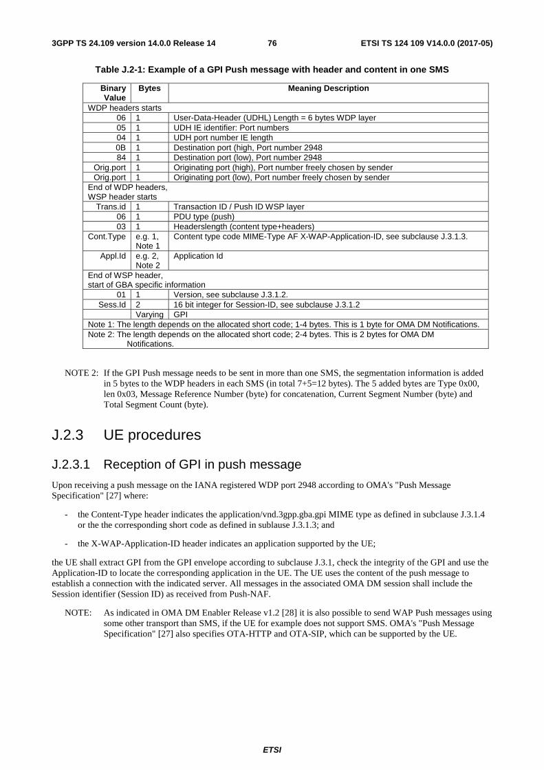
ETSI
ETSI TS 124 109 V14.0.0 (2017-05)763GPP TS 24.109 version 14.0.0 Release 14
Table J.2-1: Example of a GPI Push message with header and content in one SMS
Binary Value
Bytes Meaning Description
WDP headers starts 06 1 User-Data-Header (UDHL) Length = 6 bytes WDP layer 05 1 UDH IE identifier: Port numbers 04 1 UDH port number IE length 0B 1 Destination port (high, Port number 2948 84 1 Destination port (low), Port number 2948
Orig.port 1 Originating port (high), Port number freely chosen by sender Orig.port 1 Originating port (low), Port number freely chosen by sender
End of WDP headers, WSP header starts
Trans.id 1 Transaction ID / Push ID WSP layer 06 1 PDU type (push) 03 1 Headerslength (content type+headers)
Cont.Type e.g. 1, Note 1
Content type code MIME-Type AF X-WAP-Application-ID, see subclause J.3.1.3.
Appl.Id e.g. 2, Note 2
Application Id
End of WSP header, start of GBA specific information
01 1 Version, see subclause J.3.1.2. Sess.Id 2 16 bit integer for Session-ID, see subclause J.3.1.2
Varying GPI Note 1: The length depends on the allocated short code; 1-4 bytes. This is 1 byte for OMA DM Notifications. Note 2: The length depends on the allocated short code; 2-4 bytes. This is 2 bytes for OMA DM
Notifications.
NOTE 2: If the GPI Push message needs to be sent in more than one SMS, the segmentation information is added in 5 bytes to the WDP headers in each SMS (in total 7+5=12 bytes). The 5 added bytes are Type 0x00, len 0x03, Message Reference Number (byte) for concatenation, Current Segment Number (byte) and Total Segment Count (byte).
J.2.3 UE procedures
J.2.3.1 Reception of GPI in push message
Upon receiving a push message on the IANA registered WDP port 2948 according to OMA's "Push Message Specification" [27] where:
- the Content-Type header indicates the application/vnd.3gpp.gba.gpi MIME type as defined in subclause J.3.1.4 or the the corresponding short code as defined in sublause J.3.1.3; and
- the X-WAP-Application-ID header indicates an application supported by the UE;
the UE shall extract GPI from the GPI envelope according to subclause J.3.1, check the integrity of the GPI and use the Application-ID to locate the corresponding application in the UE. The UE uses the content of the push message to establish a connection with the indicated server. All messages in the associated OMA DM session shall include the Session identifier (Session ID) as received from Push-NAF.
NOTE: As indicated in OMA DM Enabler Release v1.2 [28] it is also possible to send WAP Push messages using some other transport than SMS, if the UE for example does not support SMS. OMA's "Push Message Specification" [27] also specifies OTA-HTTP and OTA-SIP, which can be supported by the UE.

ETSI
ETSI TS 124 109 V14.0.0 (2017-05)773GPP TS 24.109 version 14.0.0 Release 14
J.3 PDUs and parameters specific to the present document
J.3.1 GPI envelope
J.3.1.1 General
This subclause defines the GPI envelope carrying GPI as specified for the GAA bootstrap framework in 3GPP TS 33.223 [24].
J.3.1.2 Structure
The GPI envelope is coded according to figure J.3.1.2-1 and table J.3.1.2-1.
7 6 5 4 3 2 1 0
Version octet 1
Session identifier
octet 2 octet 3
GPI
octet 4 octet n
Figure J.3.1.2-1: GPI envelope
Table J.3.1.2-1: GPI envelope
The version field is in the octet 1. Version field value equal to 1 indicates that the structure is according to this document. Sending entity does not set the version field to a value not defined by this document. Receiving entity ignores any GPI envelope with version field set to unknown value. The session identifier field is in the octet 2 and the octet 3. The Session identifier field defines the identifier of the corresponding OMA DM session to be established due to the GBA Push message. The format and content definitions of the Session identifier field shall be the same as for the Session ID component in the OMA DM SYNCML header as specified in OMA Device Management Enabler Release v1.2, see [28]. The GPI field is in octets starting from octet 4 til the end of the GPI envelope.
J.3.1.3 GPI envelope short code values
The GPI envelope defined in table J.3.2-1 indicates the Content-Type in the WSP header.
Table J.3.2-1: GPI Envelope short code values
WSP header attribute Value Short code Descriptions Content-Type application/vnd.3gpp.gba.gpi To be added
The Content-Type indicates GPI envelope
Editor's note: The WSP short code for ‘application/vnd.3gpp.gba.gpi’ should be requested from Open Mobile Alliance.
J.3.1.4 IANA registration template
Editor’s note: The MIME type "application/vnd.3gpp.gba.gpi" needs to be registered in the IANA registry.
MIME media type name:
application

ETSI
ETSI TS 124 109 V14.0.0 (2017-05)783GPP TS 24.109 version 14.0.0 Release 14
MIME subtype name:
Vendor Tree – vnd.3gpp.gba.gpi
Required parameters:
None
Optional parameters:
None
Encoding considerations:
binary
Security considerations:
None
Interoperability considerations:
This content type provides a format for exchanging information in WAP push message.
Published specification:
3GPP TS 24.109
(http://www.3gpp.org/ftp/Specs/html-info/24109.htm)
Applications which use this media:
GBA Push
Intended usage:
Delivery of GBA Push information

ETSI
ETSI TS 124 109 V14.0.0 (2017-05)793GPP TS 24.109 version 14.0.0 Release 14
Annex K (informative): Change history
Change history Date TSG # TSG Doc. CR Rev Subject/Comment Old New 2004-09 CN-25 NP-040423 The draft was approved, and 3GPP TS 24.109 was then to
be issued in Rel-6 under formal change control. 2.1.2 6.0.0
2004-12 CN-25 NP-040511 001 1 Corrections and clarifications to clause 4 and example flows
6.0.0 6.1.0
2004-12 CN-25 NP-040511 002 1 Corrections and clarifications to clause 5 and example flows in annex F
6.0.0 6.1.0
2004-12 CN-25 NP-040511 003 1 Update of Authentication Proxy Procedures 6.0.0 6.1.0 2004-12 CN-25 NP-040511 005 Clarification of Ua usage 6.0.0 6.1.0 2004-12 CN-25 NP-040511 006 1 Correction of User Agent Header 6.0.0 6.1.0 2004-12 CN-25 NP-040511 007 1 B-TID transfer 6.0.0 6.1.0 2004-12 CN-25 NP-040511 008 1 AP signalling flow example 6.0.0 6.1.0 2004-12 CN-25 NP-040511 010 1 Editorials 6.0.0 6.1.0 2004-12 CN-25 NP-040512 009 1 Authorization flag transfer between AP and AS 6.0.0 6.1.0 2005-03 CN-27 NP-050082 011 1 Editorial corrections 6.1.0 6.2.0
2005-03 CN-27 NP-050130 012 2 PSK TLS updates 6.1.0 6.2.0
2005-06 CP-28 CP-050066 13 1 Format of lifetime values 6.2.0 6.3.0
2005-06 CP-28 CP-050066 15 1 User identify reference 6.2.0 6.3.0
2005-06 CP-28 CP-050066 16 Key material - Ks only 6.2.0 6.3.0
2005-06 CP-28 CP-050066 17 1 Usage of Ks_int_NAF 6.2.0 6.3.0
2005-09 CP-29 CP-050364 018 2
NAF specific key derivation 6.3.0 6.4.0
2005-09 CP-29 CP-050364 019
Missing separator character 6.3.0 6.4.0
2005-09 CP-29 CP-050369 20 1
Ks_int_NAF usage 6.4.0 7.0.0
2005-12 CP-30 CP-050539 22
Reference correction 7.0.0 7.1.0
2005-12 CP-30 CP-050551 23 1
2GGBA 7.0.0 7.1.0
2006-03 CP-31 CP-060116 025
Extension of the XML schema 7.1.0 7.2.0
2006-03 CP-31 CP-060116 027
Update of Reference PSK TLS 7.1.0 7.2.0
2006-06 CP-32 CP-060279 028
Correction of message recipient in table caption 7.2.0 7.3.0
2006-09 CP-33 CP-060454 0032 1
Realm parameter on Ub interface 7.3.0 7.4.0
2006-09 CP-33 CP-060454 0030 1
Corrections of BSF examples 7.3.0 7.4.0
2006-11 CP-34 CP-060657 0034 -
Registration of content-type "application/vnd.3gpp.bsf+xml" 7.4.0 7.5.0
2007-12 CP-38 CP-070787 0036 Interoperability problems for request on Ub reference point 7.5.0 7.6.0
2008-12 CP-42 Upgrade to Rel-8 7.6.0 8.0.0
2009-03 CP-43 CP-090160 0037 2 Introduction of GBA Push within TS 24.109 – Upa Interface 8.0.0 8.1.0
2009-06 CP-44 CP-090425 0038 Correction of key material on Upa Interface 8.1.0 8.2.0
2009-06 CP-44 CP-090424 0039 Invalid XML schema bug fix 8.1.0 8.2.0
2009-12 CP-46 Upgrade to Rel-9 8.2.0 9.0.0
2010-06 CP-18 CP-100351 0041 Privacy for Private User Identity on Ub 9.0.0 9.1.0
2011-03 CP-51 Upgrade to Rel-10 9.1.0 10.0.0
2011-09 CP-53 CP-110650 0046 Updating of references to 24.228 10.0.0 10.1.0

ETSI
ETSI TS 124 109 V14.0.0 (2017-05)803GPP TS 24.109 version 14.0.0 Release 14
Change history Date TSG # TSG Doc. CR Rev Subject/Comment Old New 2012-06 CP-56 CP-120321 0047 1 GBA_Digest procedures for 24.109 10.1.0 11.0.0
2012-06 CP-56 CP-120307 0048 1 Correct TLS version 10.1.0 11.0.0
2012-09 CP-57 CP-120598 0049 Qop for GBA_Digest 11.0.0 11.1.0
2012-09 CP-57 CP-120598 0050 1 GBA_Digest procedures for Ua interface 11.0.0 11.1.0
2012-09 CP-57 CP-120583 0051 1
Update references for TLS Extensions and PSK cyphersuites 11.0.0 11.1.0
2012-12 CP-58 CP-120794 0052 2 Realization of GBA Push delivery 11.1.0 11.2.0
2013-03 CP-59 CP-130130 0053 1 Correction of header field names in flows 11.2.0 12.0.0
2013-06 CP-60 CP-130265 0054 1
Shared key-based UE authentication with certificate-based NAF authentication - compliance 12.0.0 12.1.0
2013-06 CP-60 CP-130265 0055 Consistent usage of terminology and correction of flows 12.0.0 12.1.0
2013-06 CP-60 CP-130265 0056 Corrections of references 12.0.0 12.1.0
2013-12 CP-62 CP-130725 0062 2 GBA mode selection in NAF 12.1.0 12.2.0
2014-03 CP-63 CP-140132 0064 1 Base64 encoding of NAF specific key material 12.2.0 12.3.0
2015-03 CP-67 CP-150082 0065 2 Determination of UTC time 12.3.0 13.0.0
2016-03 CP-71 CP-160084 0067
Adding ability to signal BSF address in psk_identity_hint field for ProSe 13.0.0 13.1.0
Change history Date Meeting TDoc CR Rev Cat Subject/Comment New
version 2016-12 CP-74 CP-160752 0068 F opaque parameter 14.0.0

ETSI
ETSI TS 124 109 V14.0.0 (2017-05)813GPP TS 24.109 version 14.0.0 Release 14
History
Document history
V14.0.0 May 2017 Publication