tssr existing site-smartfren v6 15092014(enodeb+tx+sw) (6)
DESCRIPTION
Sampel TemplateTRANSCRIPT

Exhibit B.2
Huawei Technical Site Survey Report for Existing Sites
Disclaimer:
All commitments and compliances set out in each of the Exhibit of this Master Agreement have been duly clarified and confirmed, of which shall be a consecutive part of the Contract Documents, any changes from the one signed thereof will only be made upon prior written approval from PT Smart Telecom.
Vendor acknowledges and understands that the interpretation of Purchaser in respect of any matter set forth in the relevant Exhibit shall apply in any circumstance, whether or not a discrepancy may exist, and in addition to the provision of stringent requirement applies as Vendor obligations under the Contract Documents.
Notwithstanding the foregoing, Vendor warrants that the performance of Works by Vendor in respect of the specific matters in accordance with provisions set out in any Exhibit must be at all times in full compliance with, and not causing any delay to, the Required Critical Milestone Dates. Any request by Vendor of Purchaser’s review, verification and/or approval in whatsoever manner shall in no circumstances waives or reduces each and/or overall Vendor’s responsibilities with respect to the supply and delivery of each Project Item, Equipment, or Service within Network or NETWORK Platform on Turnkey Basis to meet the Network Requirements or Platform Requirements (as the case may be) under the Contract Documents.

Doc. Name: Exhibit B.2 Site Survey detailed sites-wise design [Contract No]
Exhibit B.2
Huawei Technical Site Survey Report for Existing Sites
All commitments and compliances set out in each of the Exhibit of this Master Agreement have been duly clarified and confirmed, of which shall be a consecutive part of the Contract Documents, any changes from the one signed thereof will only be made upon prior written approval from PT Smart Telecom.
Vendor acknowledges and understands that the interpretation of Purchaser in respect of any matter set forth in the relevant Exhibit shall apply in any circumstance, whether or not a discrepancy may exist, and in addition to the provision of stringent requirement applies as Vendor obligations under the Contract Documents.
Notwithstanding the foregoing, Vendor warrants that the performance of Works by Vendor in respect of the specific matters in accordance with provisions set out in any Exhibit must be at all times in full compliance with, and not causing any delay to, the Required Critical Milestone Dates. Any request by Vendor of Purchaser’s review, verification and/or approval in whatsoever manner shall in no circumstances waives or reduces each and/or overall Vendor’s responsibilities with respect to the supply and delivery of each Project Item, Equipment, or Service within Network or NETWORK Platform on Turnkey Basis to meet the Network Requirements or Platform Requirements (as the case may be) under the Contract Documents.

Technical Site Survey Report
Site ID
Vendor ID
Site Name
Site Address
SMARTFREN Contact Person
Huawei Contact Person Cisuritami
Surveyor
Survey Date

Technical Site Survey Report
Site Survey Report (CDMA Site)
All information contained herein the document is confidential! Page 5
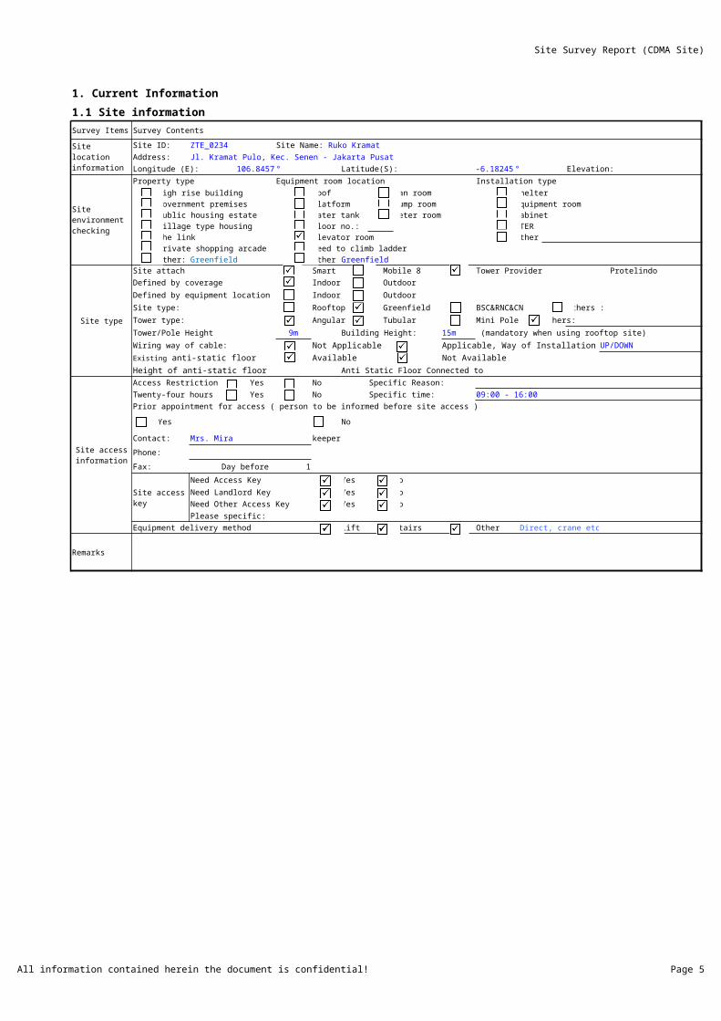
1. Current Information
1.1 Site information
Survey Items Survey Contents
Site ID: ZTE_0234
Address: Jl. Kramat Pulo, Kec. Senen - Jakarta Pusat
Longitude (E): 106.8457 ° Latitude(S): -6.18245 ° Elevation:
Property type Equipment room location Installation type
High rise building Roof Fan room ShelterGovernment premises Platform Pump room Equipment roomPublic housing estate Water tank Meter room CabinetVillage type housing Floor no.: CTERThe link Elevator room Other : Private shopping arcade Need to climb ladder Other: Greenfield Other : Greenfield
Site type
Site attach Smart Mobile 8 Tower Provider Protelindo
Defined by coverage Indoor Outdoor
Defined by equipment location Indoor Outdoor
Site type: Rooftop Greenfield BSC&RNC&CN Others :
Tower type: Angular Tubular Mini Pole Others:
Tower/Pole Height 9m Building Height: 15m (mandatory when using rooftop site)
Wiring way of cable: Not Applicable Applicable, Way of Installation :
Available Not Available
Height of anti-static floor Anti Static Floor Connected to
Access Restriction Yes No Specific Reason:
Twenty-four hours Yes No Specific time: 09:00 - 16:00
Prior appointment for access ( person to be informed before site access )
Yes No
Contact: Mrs. Mira keeper
Phone:
Fax: Day before : 1
Site access key
Need Access Key Yes No
Need Landlord Key Yes No
Need Other Access Key Yes No
Please specific:
Equipment delivery method Lift Stairs Other Direct, crane etc..
Remarks
Site location information
Site Name: Ruko Kramat
Site environment checking
Existing anti-static floor
Site access information

Site Survey Report (CDMA Site)
All information contained herein the document is confidential! Page 6
1.2 Existing Equipment information
CDMA800 CDMA1900
System CDMA800 CDMA1900 Rectifier Rack 19' Others:Rack Qty 1 1 1
Power supply
AC DC
Voltage: 220 V Voltage: 52.7 VDC
Electricity PLN : 13.2 KVA Current Load : 40.7 A
Main Breaker at KWH : 3x20 A Max Rectifier Module : qty :
Three phases Single phase Rectifier Module Equipped : qty :
Current Load Load R: 5.81 A Each Rectifier Module Capacity : 50 A
Load S: 5.46 A Max Battery Bank Qty : 2 Bank
Load T: 2.77 A Battery Bank Equopped Qty : 2 Bank
Rectifier MCB capacity at ACPDB: 3x16 A Each Battery Capacity : 150 AH
Spare Breaker Qty: 1:3Px16A,2:1Px4A,1:1Px6A LLVD 1 MCB spare (qty&spare) : 2x16A,2x32A,1x63A,2x100A
LLVD 2 MCB spare (qty&spare) : 1x16A,2x32A,2x63A
Qty of Available Breaker Slots: N/A Total output current: 170 A (including battery charging load)
Input Capacity: 13.2 Output Capacity: 3.0888 Load current: 40.7 A
Air Conditioner : 2 x 2 pk :condition: Good Total output power: 8959 W (including battery charging load)
x pk :condition: Load power : 2144.89 W
DC Fan : x set :condition:
Type: FT12-150 (12V,150AH) Brand: LEOCH Model: AGM GEL Manufacture date: 05 Jul 2013
Battery Visual Condition Check (No Leakage, No Corrosion, No Crack, No Swollen, etc.)
Battery Group Block -1 Block -2 Block -3 Block -4Bank -1 OK OK OKBank -2 OK OK OK
Bank -3 - - - -
Bank -4 - - - -
Battery Voltage Measurement :
Battery Group Block -1 Block -2 Block -3 Block -4
Bank -1 13.3 V 13.3 V 13.3 V 13.3 V
Bank -2 13.3 V 13.3 V 13.3 V 13.3 V
Bank -3
Bank -4 - - - -
Grounding
Grounding bar Qty (Outdoor): 3 Spare GND port Qty (Outdoor): 1;3;5
Grounding bar Qty (Indoor): 1 Spare GND port Qty (Indoor): 11
Grounding Resistance Measurement : (Ohm) Grounding Bar Material: Indoor Aluminum
Outdoor Aluminum
Total hole Qty: 12 Spare Qty: -
Notes:
Length Pole GPS:
Length Of GPS Cable to BTS: 35 m
GPS Antenna Height: RT. 15 + 3
Remarks
Existing equipmentconfiguration information
Feeder outlet(FEP)
Existing GPS System
Site Survey Report (CDMA Site)
All information contained herein the document is confidential! Page 7
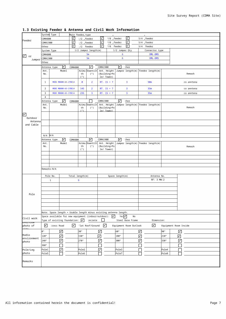
1.3 Existing Feeder & Antenna and Civil Work Information
Feeder
System Type Main feeder type
CDMA800 1/2” feeder 7/8” feeder 5/4” feeder
CDMA1900 1/2” feeder 7/8” feeder 5/4” feeder
Other 1/2” feeder 7/8” feeder 5/4” feeder
System Type 1/2 Jumper length(m) 1/2 Jumper Qty Connector type
CDMA800 5m 6 DML-DMS
CDMA1900 5m 6 DML-DMS
Other
Antenna type CDMA800 CDMA1900 Other
Model Downtilt (º) Jumper length(m) Feeder length(m)Remark
1 MOBI MB800-65-17DE14 0 2 RT. 15 + 7 3 50m co anntena
2 MOBI MB800-65-17DE14 145 2 RT. 15 + 7 3 35m co anntena
3 MOBI MB800-65-17DE14 235 3 RT. 15 + 7 3 35m co anntena
4
Antenna type CDMA800 CDMA1900 Other
Model Downtilt (º) Jumper length(m) Feeder length(m)Remark
N/A N/A
Antenna type CDMA800 CDMA1900 Other
Model Downtilt (º) Jumper length(m) Feeder length(m)
Remark
Remarks:N/A
Pole
Pole No. Total length(m) Spare length(m) Antenna No.
1 9 RF: 3 MW:2
Note: Spare length = Usable length minus existing antenna length.
Civil workSpace available for new equipment (indoor/outdoor): Yes No
Type of existing foundation: Concrete Steel Base Frame Dimension:
Access Road Flat Roof/Ground Equipment Room Outlook Equipment Room Inside
0° 30° 60° 90°
120° 150° 180° 210°
240° 270° 300° 330°
360°
Pole/Leg photoPole1 Pole2 Pole3 Pole4
Pole5 Pole6 Pole7 Pole8
Remarks
Indoor Jumper
Outdoor Antenna and
Cable
Ant. No.
Azimuth (º)
Ant. Height (Building+Pole/
Tower) (m)
Ant. No.
Azimuth (º)
Ant. Height (Building+Pole/
Tower) (m)
Ant. No.
Azimuth (º)
Ant. Height (Building+Pole/
Tower) (m)
Overview photo of site
Radio environment photo

Site Survey Report (CDMA Site)
All information contained herein the document is confidential! Page 8
1. Current Information
1.1 Site information
Survey Contents
Jl. Kramat Pulo, Kec. Senen - Jakarta Pusat
Elevation:
Installation type
Protelindo
UP/DOWN
09:00 - 16:00
Prior appointment for access ( person to be informed before site access )
Ruko Kramat
Site Survey Report (CDMA Site)
All information contained herein the document is confidential! Page 9
1.2 Existing Equipment information
6
4
2x16A,2x32A,1x63A,2x100A
1x16A,2x32A,2x63A
(including battery charging load)
(including battery charging load)
Block -4
-
-
Block -4
13.3 V
13.3 V
-
1;3;5
11
Cuprum
Cuprum

Site Survey Report (CDMA Site)
All information contained herein the document is confidential! Page 10
1.3 Existing Feeder & Antenna and Civil Work Information
Main feeder type
Remark
co anntena
co anntena
co anntena
Remark
Remark
Remarks:N/A

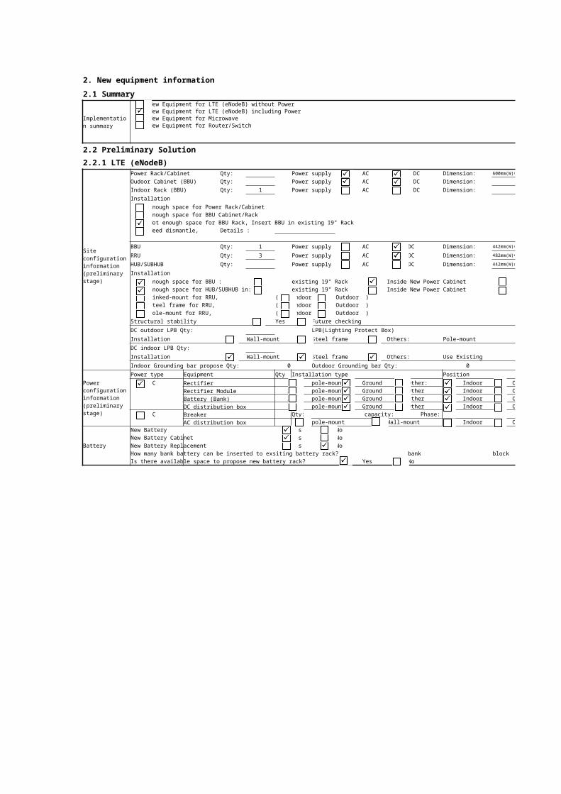
2. New equipment information
2.1 SummaryNew Equipment for LTE (eNodeB) without PowerNew Equipment for LTE (eNodeB) including PowerNew Equipment for MicrowaveNew Equipment for Router/Switch
2.2 Preliminary Solution
2.2.1 LTE (eNodeB)Power Rack/Cabinet Qty: Power supply AC DC Dimension: 600mm(W)×600mm(D)×2000mm(H)
Oudoor Cabinet (BBU) Qty: Power supply AC DC Dimension:
Indoor Rack (BBU) Qty: 1 Power supply AC DC Dimension:
Installation
Enough space for Power Rack/CabinetEnough space for BBU Cabinet/RackNot enough space for BBU Rack, Insert BBU in existing 19" RackNeed dismantle, Details :
BBU Qty: 1 Power supply AC DC Dimension: 442mm(W)×310mm(D)×86mm(H)
RRU Qty: 3 Power supply AC DC Dimension: 482mm(W)×270mm(D)×140mm(H)
HUB/SUBHUB Qty: Power supply AC DC Dimension: 442mm(W)x220mm(D)x 43.6mm(H)
Installation
Enough space for BBU : existing 19" Rack Inside New Power CabinetEnough space for HUB/SUBHUB in: existing 19" Rack Inside New Power CabinetLinked-mount for RRU, ( Indoor Outdoor )Steel frame for RRU, ( Indoor Outdoor )Pole-mount for RRU, ( Indoor Outdoor )
Structural stability Yes Future checking
DC outdoor LPB Qty: LPB(Lighting Protect Box)
Installation Wall-mount Steel frame Others: Pole-mount
DC indoor LPB Qty:
Installation Wall-mount Steel frame Others: Use Existing
Indoor Grounding bar propose Qty: 0 Outdoor Grounding bar Qty: 0
Power type Equipment Qty Installation type Position
DC Rectifier 1 pole-mount Ground Other: Indoor OutdoorRectifier Module 2 pole-mount Ground Other Indoor OutdoorBattery (Bank) 2 pole-mount Ground Other Indoor OutdoorDC distribution box 1 pole-mount Ground Other Indoor Outdoor
AC Breaker Qty: capacity: Phase:AC distribution box pole-mount Wall-mount Indoor Outdoor
Battery
New Battery Yes NoNew Battery Cabinet Yes NoNew Battery Replacement Yes NoHow many bank battery can be inserted to exsiting battery rack? bank blockIs there available space to propose new battery rack? Yes No
Implementation summary
Siteconfiguration information(preliminary stage)
Power configuration information (preliminary stage)
Cable
Power cable
eNodeB(DCDU)-Rectifier DC length: 2 m
eNodeB-MCB AC length: NA m
DC power(Rectifier) - MCB AC length: 8 m
m
power rack/cabinet GND cable length: 10 m
Cable for Indoor or outdoor coverage site?
Indoor RRU-MCB AC power cable length: NA m
RRU-Rectifier or DCDU DC power cable length: (1*60 + 2*40) m
Fiber length (BTS to RRU) : (1*60 + 2*40) m
BBU GND cable length : 10 m
Outdoor Cable type Sct1 Sct2 Sct3 Sct4 Sct5 Sct6
Feeder cable (BTS to Ant.) (Qty*Length(m))
Feeder/jumper cable (RRU to Ant.) (Qty*Length(m))4x3 4x3 4x3
DC Indoor LPB - DC outdoor LPB DC power cable (Qty*Length(m))DC outdoor LPB - RRU (Qty*Length(m))
RRU GND cable length (m) 10 10 10
Fiber cable (BTS to RRU) (Qty*Length(m))(1*60 + 2*40) m
Feeder cable trayNew vertical cable tray required: Yes No length:
New horizontal cable tray required: Yes No length:
Transmission cable type: Optical Cable Transmission cable connector: LC-FC
Transmission cable length: 10 m
RRU installation
Indoor Outdoor
1/2” Jumper length (RRU to existing feeder system)Feeder/Jumper length (RRU to Antenna)
Sct1: 3 m Feeder/Jumper type: 1/2" 7/8"
Cell1: m Qty: Sct2: 3 m Feeder/Jumper type: 1/2" 7/8"
Cell2: m Qty: Sct3: 3 m Feeder/Jumper type: 1/2" 7/8"
Cell3: m Qty: Sct4: m Feeder/Jumper type: 1/2" 7/8"
Sct5: m Feeder/Jumper type: 1/2" 7/8"
Sct6: m Feeder/Jumper type: 1/2" 7/8"
Length Pole of GPS antenna m
Length Of GPS Cable to BBU 30 m
GPS Antenna Height 3.5 m
Cable type Φ9mm 1/2" 7/8" RG-8U
Delete antenna
Ant. Model Ant. Model Ant. No. Ant. Model
1 1
2 2
3 3
4 4
Add antenna
Ant. Model Ant. height (m) Azimuth (°) Downtilt (°) Remark
N1 1 ADU451816v01 42 40 0 Az follow existingN2 2 ADU451816v01 42 40 120
N3 3 ADU451816v01 42 40 240
N4 4
N/A N/A
N/A N/A
Civil work
Propose new foundation outdoor: Yes No Dimension:
Propose new sun shield: Yes No
Propose extend shelter : Yes No
Propose new air conditioner : Yes No qty : x pk
Propose upgrade electricity : …… VA, from …. VA to : …. VA
Comments:
Equipment No Equipment name Qty Dimension
1 1
2
3
4
5
Remarks
DC Indoor LPB – rectifier length:
Proposed GPS System (if any)
Antenna suggestion (preliminary stage)
Ant. No.
PoleNo./Tower leg
Ant. No.
PoleNo.
PoleNo.
New Ant.
PoleNo./Tower leg
Pole/Towerheight(m)
Obsolete equipment list

2. New equipment information
2.1 Summary
2.2 Preliminary Solution
2.2.1 LTE (eNodeB)600mm(W)×600mm(D)×2000mm(H)
442mm(W)×310mm(D)×86mm(H)
482mm(W)×270mm(D)×140mm(H)
442mm(W)x220mm(D)x 43.6mm(H)
Inside New BBU CabinetInside New BBU Cabinet
Position
Outdoor Outdoor Outdoor Outdoor
Outdoor

5/4"
5/4"
5/4"
5/4"
5/4"
5/4"
Remark
Dimension

2.2.2 TransmissionEquipment Type: MW Optical Transceiver HDSL Direct connect to 2M wire
Transmission Medium: MW Optical Fiber HDSL 2M wire FE/RJ45
Transmission Cable Type: E1 T1 75ohm 120ohm Others: Fiber
ODF Type: FC SC DDF Type: LSA
Existing Microwave Antena Load Info(All Existing Antena)
Item Tower LegFar end site
Antenna Brand Antenna Type Azimuth Operator Configuration RemarkSite ID Site Name
1 A
2 B
3 C
4
5
6
7
8
9Existing IDU/ODU (Microwave)
Item Far end site IDU Type Capacity Config ODU Link Frequency
RemarkSite ID Site Name Type Suband Hi,Lo Tx Rx Frame Type
1
2345678910
Existing Transport
ItemFar end site
CapacityEquipment
RemarkSite ID Site Name Type Available Port
1 Mux/Router2345678910
Remarks:
Proposed New Antenna Information for Smartfren
Item Far End ID far End Site Name Antena Size Antena Height Tower Leg Azimuth Remark
1
2
3
456
New Proposed IDU/ODUItem Far end site IDU Type Capacity Config ODU
RemarkSite ID Site Name Type Hi,Lo Frame Type
1234567
New Proposed Transport
Item
Far end site
Capacity
Equipment Space Power MCB
RemarkSite ID Site Name Type Requirement Port (OK/NOK) (Watt) (Axpcs)
1234567
8
9
10
Cable length Information
Item Length (Meters/pc) Qty Remark
DC Power Cable from IDU to rectifier
If Cable layout from IDU to bottom of tower (all direction)
Ethernet cable from IDU to BBU
2M Trunk cable from IDU to DDF (If any)E1 Jumper from existing DDF to Proposed DDF (if any)IDU grounding cable to grounding pointOptical Patch cord from IDU to ODF
Distance from ODU Grounding cable to Grounding Point
MW mounting pole Information (new Proposed)
ItemFar End Site
Mounting Pole Dia.Mounting Pole height Mounting Pole Leg Mounting Pole azzimuth
Site ID Site name
1
2
3456789
Existing Outdoor Busbar on Tower(From down to top)
Amount of busbar on tower Set
Height of busbar 1 Meter
Height of busbar 2 Meter
Height of busbar 3 Meter
Remarks:
Existing Transmission
Antenna Size
Antena height
Antena frequency
ODU Frame Support
Transport Type
Proposed Transmission
New Antenna Space Available
ODU Frame Support
Transport Type Cabinet/
Subrack qty
Remark: The cable length must be measured from proposed New Installation Position (cabinet/19" subrack, IDU, rectifier, DCPDB, etc)

2.2.3 New Transport Auxiliary Information
NEW EQUIPMENT
Insert in existing 19" RackInsert in new Indoor 19" Rack/Outdoor BBU CabinetInsert in new Power RackNeed dismantle, details :
-Power Alocation : * MCB Allocation-1: _______; Capacity: _______ * MCB Allocation-2: _______; Capacity: _______- Power Cables (Blue & Black): * Blue Cable Length : _______m * Black Cable Length : _______m * Yellow Green Cable Length : _______m * Connect to : _______
- FE Cables: * Length : _______m * Connect to : _______ * Port Number : _______- Optical Cables/Patch Core: * Length : _______m * Connect to : _______ * Port Number : _______ * Peer connector type : ___FC/SC____- Optical Cables/Patch Core: * Length : _______m * Connect to : _______ * Port Number : _______ * Peer connector type : ___FC/SC____- E1 Cable : * Length : _______m * Connect to : _______ * Port Number : _______ * Peer connector type : _______
Remarks:
-Position NEW EQUIPMENT:* Position NEW EQUIPMENT:

Site Photo Check ListSN Detail Photo Taken Number of Photos
A Site Overview Photo1 Access Road
2 Existing Site Front View
3 Existing Site Gate
4 Existing Surrounding View
5 Existing Tower (overview)
6 Existing Tower (Leg A)
7 Existing Tower (Leg B)
8 Existing Tower (Leg C)
9 Existing Tower (Leg D)
10 Existing Shelter & Foundation, Stairs etc
11 Existing Oudoor Foundation
B Existing Equipment Information1 Power
a Existing KWH Meter
b Existing main MCB at KWH meter
c Existing ACPDB
d Existing AC Current Load
e Existing Air Conditioner (indoor site)
f Existing DC Fan (indoor site)
g Existing Rectifier Cabinet
h Existing DC Current Load
i Existing DCPDB internal (at rectifier rack)
j Existing DCPDB external (outside rectifier rack)
k Existing Battery System
l Others: (Specify)
2 RF
a Existing RF Antenna
b RF Component in Sector 1
c RF Component in Sector 2
d RF Component in Sector 3
3 Microwave
IDU
a IDU Rack 1 over view
b IDU Rack 2 over view
c IDU-1 Installation Label
d IDU-1 Factory Label
e IDU-2 Installation Label
f IDU-2 Factory Label
g IDU-3 Installation Label
h IDU-3 Factory Label
i IDU-4 Installation Label
j IDU-4 Factory Label
k IDU-5 Installation Label
l IDU-5 Factory LabelODU and Antenna
a Photo of MW Antenna
b Photo of MW Antenna
c Antenna-1 Total View
d Antenna-1 Factory Label
e Antenna-1 Installation Label
f Waveguide Interface to Antenna-1 (if have)
g ODU-1 Frame Label (1+0 or 1+1)-if have
h ODU-1 Factory Label
i ODU-1 Installation Label
j Others: (Specify)
k Antenna-2 Total View
l Antenna-2 Factory Label
m Antenna-2 Installation Label
n Waveguide Interface to Antenna-2 (if have)
o ODU-2 Frame Label (1+0 or 1+1)-if have
p ODU-2 Factory Label
q ODU-2 Installation Label
r Others: (Specify)
4 Indoor/Outdoor Shelter
a Existing Cable Ladder
b Existing Indoor Grounding Bar
c Existing Outdoor Grounding Bar
d Existing Inlet grounding bar
e Existing Inlet
f Existing Transmission Equipment
g Existing DDF
h Tower Busbar 1
i Tower Busbar 2
j Tower Busbar 3
k Existing NE
l Existing NE
m Existing NE
n Existing NE
o Existing NE
p Others: (Specify)
5 Existing ODF, DDF & FIBER
a Existing ODF
b Existing ODF
c Existing DDF
d Existing DDF
e Existing Fiber
f Existing Fiber
C Panoramic Surroundings Overview
1 0 degree
2 30 degree
3 60 degree
4 90 degree
5 120 degree
6 150 degree
7 180 degree
8 210 degree
9 240 degree
10 270 degree
11 300 degree
12 330 degree
D New Equipment Proposal1 Proposed New Indoor Equipment LTE
2Proposed New Vertical Cable Ladder For Cabinet
3 Proposed Cable Routing for LTE
4 Proposed New Inlet for LTE
5Proposed Reuse existing MGB for LTE (Indoor)
6Proposed Reuse Existing MGB on Tower for LTE (Outdoor)
7 Proposed new MGB on Tower for LTE
8 Proposed AC Power System
9 Proposed New RF Antenna & RRU
10 Proposed Jumper from Antenna to RRU
11 Proposed New GPS Antenna for LTE
12 Proposed New Outdoor cabinet
13 Proposed Rectifier System
14 Proposed New Battery
15 Proposed New Cable Ladder
16 Proposed Transmission Equipment (IDU)
17 Proposed Transmission Equipment (ODU)
18Proposed MW Antenna Position, and Direction to far end
19 Proposed Router Equipment
20 Proposed Switch Equipment
21 Proposed ODF/OTB Equipment
22Others: (Specify : new rack, cable route, new DCPDB, etc)
Comment:

3. Site PhotoA Site Overview Photo
Access Road Existing Site Front View
Existing Site Gate Existing Surrounding View
Existing Tower (overview) Existing Tower (Leg A)
Existing Tower (Leg B) Existing Tower (Leg C)

Existing Tower (Leg D) Existing Shelter & Foundation, Stairs etc
Existing Oudoor Foundation
B Existing Equipmet Information1 POWER
Existing KWH Meter Existing main MCB at KWH Meter
Existing ACPDB Existing AC Current Load

Existing Air Conditioner (indoor site) Existing DC Fan (indoor site)
Existing Rectifier Cabinet Existing DC Current Load
Existing DCPDB internal (at rectifier rack) Existing DCPDB external (outside rectifier rack)
Existing Battery System Others: (Specify)

2 RF
Existing RF Antenna RF Component in Sector 1
RF Component in Sector 2 RF Component in Sector 3
3 MICROWAVE
IDU Rack 1 Over View IDU Rack 2 Over View
IDU-1 Installation Label IDU-1 Factory Label
IDU-2 Installation Label IDU-2 Factory Label
IDU-3 Installation Label IDU-3 Factory Label
IDU-4 Installation Label IDU-4 Factory Label
IDU-5 Installation Label IDU-5 Factory Label
ODU`
Photo of MW Antenna Photo of MW Antenna
Antenna-1 Total View Antenna-1 Factory Label
Antenna-1 Installation Label Waveguide Interface to Antenna-1 (if have)
ODU-1 Frame Label (1+0 or 1+1)-if have ODU-1 Factory Label

`
ODU-1 Installation Label Others: (Specify)
Antenna-2 Total View Antenna-2Factory Label
Antenna-2 Installation Label Waveguide Interface to Antenna-2 (if have)
ODU-2 Frame Label (1+0 or 1+1)-if have ODU-2Factory Label

`
ODU-2 Installation Label Others: (Specify)
4 INDOOR/OUTDOOR SHELTER/CORE ROOM`
Existing Cable Ladder Existing Indoor Grounding Bar
`
Existing Outdoor Grounding Bar Existing Inlet grounding bar
Existing Inlet Existing Transmission Equipment
`
Existing DDF Tower Busbar 1
`
Tower Busbar 2 Tower Busbar 3
`
Existing NE Existing NE
Existing NE Existing NE

Existing NE Others(Spesify)
5 EXISTING ODF,DDF & FIBER
Existing ODF Existing ODF
Existing DDF Existing DDF
Existing Fiber Existing Fiber
C Panoramic Surroundings Overview
EN 0° EN 30°
EN 60° EN 90°
EN 120° EN 150°
EN 180° EN 210°

EN 240° EN 270°
EN 300° EN 330°
D New Equipment Proposal
Proposed New Indoor Equipment LTE Proposed New Vertical Cable Ladder For Cabinet
Proposed Cable Routing for LTE Proposed New Inlet for LTE

Proposed Reuse existing MGB for LTE (Indoor) Proposed Reuse Existing MGB on Tower for LTE (Outdoor)
Proposed new MGB on Tower for LTE Proposed AC Power System
Proposed New RF Antenna & RRU Proposed Jumper from Antenna to RRU
Proposed New GPS Antenna for LTE Proposed New Outdoor cabinet

Proposed Rectifier System Proposed New Battery
Proposed New Cable Ladder Proposed Transmission Equipment (IDU)
Proposed Transmission Equipment (ODU) Proposed MW Antenna Position, and Direction to far end
Proposed Router Equipment Proposed Switch Equipment

Proposed ODF/OTB Equipment Others: (Specify : new rack, cable route, new DCPDB, etc)

`4.1 Current RAN system configuration from SMART
SHELTER EXISTING TANPA TRAY
4.2 Preliminary stage RAN system configuration
SHELTER LAYOUT DENGAN PROPOSED TANPA TRAY

4.3 Commecial stage RAN system configuration
TOWER LAYOUT
4.4 Existing Equipment room layout
SHELTER LAYOUT DENGAN PROPOSED DENGAN TRAY

4.5 Equipment room cable routing
SHELTER LAYOUT DENGAN PROPOSED DENGAN TRAY DENGAN KABEL ROUTE (DITAMBAH ROUTE UNTUK KABEL TRANSMISI)
4.6 Rooftop site layout and cable routing
site LAYOUT/ ROOF TOP LAYOUT

SHELTER EXISTING TANPA TRAY
SHELTER LAYOUT DENGAN PROPOSED TANPA TRAY

TOWER LAYOUT
SHELTER LAYOUT DENGAN PROPOSED DENGAN TRAY

SHELTER LAYOUT DENGAN PROPOSED DENGAN TRAY DENGAN KABEL ROUTE (DITAMBAH ROUTE UNTUK KABEL TRANSMISI)
site LAYOUT/ ROOF TOP LAYOUT

Site Survey Report (GSM and UMTS Site)
5.Survey Memorandum
Signature of SMARTFREN representative:
Date:
Signature of HUAWEI’s representative:
Date:
Note: This survey report provides the basic data for equipment commissioning, and shall not be modified once confirmed by both parties. If the user needs to modify the data due to special reasons, contact the local office of HUAWEI in time. HUAWEI shall not be responsible for the delay in project implementation due to the modification of the survey results required by the user.
SMARTFREN comments
HUAWEI’s comments

Site Survey Report (GSM and UMTS Site)
Note: This survey report provides the basic data for equipment commissioning, and shall not be modified once confirmed by both parties. If the user needs to modify the data due to special reasons, contact the local office of HUAWEI in time. HUAWEI shall not be responsible for the delay in project implementation due to the