tt castironws brochure dk3 replaceable out · 6. opcional: en mezclas secas o más húmedas un peso...
TRANSCRIPT

ADA DETECTABLE WARNING PRODUCTS
R
R
Wet-SetADA COMPLIANT • DURABLE • REPLACEABLE
www.TufTile.com
TufTile’s 165,000 sq. ft. manufacturing and distribution facility is located in Lake Zurich, IL.
PolymerRadius

HIGH-IMPACT POLYMER TILES WET-SET (REPLACEABLE)
Wet-Set (Replaceable) TilesTufTile® WS is a UV stabilized, high-impact polymer engineered for superior impact-resistance, slip-resistance,wear-resistance, and long-term durability for new construction installations.
TufTile’s unique umbrella designed anchors lock the tile securely into the concrete without displacing aggregate or trapping air beneath the tile’s surface.
Concrete Keepers™ integrate with concrete “slurry” holding tile fast when concrete cures.
TufTile’s exclusive design incorporates slip-resistant truncated domes molded to exact ADA specifi cation for detectable warning systems. Homogenous materials, uniformly distributed throughout the thickness of the tile provides for superior strength and color stability.
TufTile’s low profi le coupled with beveled perimeter edges provides for an easy, safe transition from surrounding surfaces. This unique (replaceable) design is lightweight, strong and fl exible so installations are effi cient and easy.
TufTile® ADA Tiles have a 5-Year Limited Warranty – see website or contact customer service.
TUFTILE® TACTILE IS ADAAG / PROWAG / CA TITLE 24 COMPLIANT
PAT. NO. US D691,743 S
ADA DETECTABLE WARNING PRODUCTS
1-888-960-8897TufTile.comM A D E I N
U S A
Tiles shipped with anchors installed
Protective sheeting ensures installation
cleanliness

ADA DETECTABLE WARNING PRODUCTS
M A D E I N
U S A
ADA DETECTABLE WARNING PRODUCTS
#TAC-PWSCB01141200 Flex Court Lake Zurich, IL 60047
1-888-960-8897TufTile.com
Molded manufacture identifi cation
Stainless tamper-resistant 1-1/2” screw
Self-threading corrosion-resistant composite anchors
Tamper-resistant stainless fasteners provide
security and effi cient tile replacement if required
Concrete Keepers™ (located on underside of TufTile) integrate with concrete “slurry” holding tile fast when concrete cures
Beveled edges provide excellent transition egress
In-Line truncated domes comply with all ADA Specifi cations
ADA Compliant wet and dry slip-resistant surfaces
2.35”
2.35”
TUFTILE WET-SET (REPLACEABLE) TILES
English and Spanish installation
instructions are attached to each tile
BRICK REDFED 22144
COLOR I.D. BRD
YELLOWFED 33538
COLOR I.D. YEL
COLONIAL REDFED 20109
COLOR I.D. CRD
SIZES Tiles/Carton Cartons/Pallet COLORS2’ X 1’ 10 122’ X 2’ 10 122’ X 3’ 6 122’ X 4’ 5 122’ X 5’ 4 12
Tiles shipped with anchors installed
Fastener locations
Simplify Wet-Set installation by connecting panels.
Wedges are sized per the radius of the arc. All fi eld tiles are 2’ x 2’.
25 foot radius line
COLORSRadius 15 Foot20 Foot Colors to match corresponding
Polymer tiles25 Foot30 Foot
POLYMER RADIUS TILES
Fastener locations
Made in USA
Molded in TufTile identifi cation
TT-CONNECTOR
DARK GRAYFED 36118
COLOR I.D. GRY
BLACKFED 17038
COLOR I.D. BLKCOLOR I.D. BLK
SAFETY REDFED 31350COLOR I.D. SRD

TufTile Wet-Set Packaging Design
Location of 24” Lid SupportsPanel Corner Packaging Protection
Location of Carton Product Labels Carton Product Label
Panel Size 2’ x 1’ 2’ x 2’ 2’ x 3’ 2’ x 4’ 2’ x 5’Units/Carton 10 10 6 5 4Cartons/Pallet 12 12 12 12 12
Units/Pallet 120 120 72 60 48Weight 380 721 lbs 666 lbs 735 lbs 716 lbsDimensions 48”x48”x52” 48"x48"x82" 54"x40"x85" 52"x52"x72" 52"x62"x56"
Panel Sizes, Quantities and Packaging Dimensions
TT-PKG-WS
ADA DETECTABLE WARNING PRODUCTS


2’ X 1’ WET-SET(REPLACEABLE)
ADA DETECTABLE WARNING PRODUCTS
TACTILE TILE2.350 DOME SPACING
TEL 888-960-8897 FAX 847-550-8004 www.tuftile.com

2’ X 2’ WET-SET(REPLACEABLE)
ADA DETECTABLE WARNING PRODUCTS
TEL 888-960-8897 FAX 847-550-8004 www.tuftile.com
TACTILE TILE2.350 DOME SPACING

2’ X 3’ WET-SET(REPLACEABLE) TEL 888-960-8897 FAX 847-550-8004 www.tuftile.com
TACTILE TILE2.350 DOME SPACING
ADA DETECTABLE WARNING PRODUCTS

2’ X 4’ WET-SET(REPLACEABLE) TEL 888-960-8897 FAX 847-550-8004 www.tuftile.com
TACTILE TILE2.350 DOME SPACING
ADA DETECTABLE WARNING PRODUCTS

2’ X 5’ WET-SET(REPLACEABLE) TEL 888-960-8897 FAX 847-550-8004 www.tuftile.com
TACTILE TILE2.350 DOME SPACING
ADA DETECTABLE WARNING PRODUCTS

POLYMER DETECTABLE WARNING RADIUS—WEDGE TILE
15R WET SET
(REPLACEABLE) TEL 888-960-8897 FAX 847-550-8004 www.tuftile.com

POLYMER DETECTABLE WARNING RADIUS—WEDGE TILE
20R WET SET
(REPLACEABLE) TEL 888-960-8897 FAX 847-550-8004 www.tuftile.com

POLYMER DETECTABLE WARNING RADIUS—WEDGE TILE
25R WET SET
(REPLACEABLE) TEL 888-960-8897 FAX 847-550-8004 www.tuftile.com
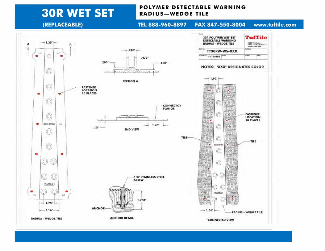
POLYMER DETECTABLE WARNING RADIUS—WEDGE TILE
30R WET SET
(REPLACEABLE) TEL 888-960-8897 FAX 847-550-8004 www.tuftile.com

TufTile® INSTALLATION INSTRUCTIONSWET-SET (REPLACEABLE)
1. Read these instructions thoroughly before you begin. Consult the Access-Board,PROWAG guidelines R208 & R305 for tile placement location before beginning.Go to www.TufTile.com for Federal compliance documents.
The proper slump range will ensure TufTiles maintain a solid connection with the cured concrete.
3. For Radius or Connected Tiles, see below. For normal tile install, do not removeprotective plastic covering from TufTile until it’s installed and concrete isfully cured.
4. Slowly press the TufTile into the wet concrete until the base of the truncated(Figure 1) Do not stand on the tile during
installation. (TufTile polymer products are not recommended for asphaltinstallations)
5. To ensure proper integration between TufTile WS anchors, *Concrete Keeers™,and the concrete it is important to tap the entire TufTile surface with a rubbermallet. (Figure 2) *Concrete Keepers™ are a feature of TufTile polymerproducts only.
6. OPTIONAL: In drier or wetter concrete mixes a weight like a sand bag or blockmay be laid on top of the installed tile to hold the tile at the desired depth
(Figure 3)
7. IMPORTANT! WHILE THE CONCRETE IS WORKABLE, AN 1/8” DEEP TROW- ELED EDGE MUST BE INSTALLED AROUND THE TILE PERIMETER. (Fig. 4)
TufTile until the concrete is fully cured.
9. Remove protective plastic sheeting after all post-installation treatments are complete and the concrete has cured. TufTile'sunder the tile and can be fully removed. Your TufTile installation is nowcomplete.
Additional installation information including an installation tutorial is available at www.TufTile.com
If you have any additional questions please contact TufTile®
Thank you for your business!1-888-960-8897
www.TufTile.com
Radius or Connected TufTile® InstallationInstead of Step 3 above, do the following:
3. Peel back the protective coating on the tile edges.
3a. Remove anchors from edges that join.
3b. Insert Radius or Connector part between the tiles.
3c. Re-install anchors through tile and Radius or Connector.
3d. Locate the complete surface in position over wet concrete
Resume installation at Step 4 above
Concrete
1/8” Deep Troweled Edge
Concrete
R a d i u s
C o n n e c t o r
T I L E
Connected Radius Example

Concreto
1/8” del borde profundo llana
Concreto
R a d i u s
C o n n e c t o r
T I L E
Ejemplo radio Conectado
TufTile® INSTRUCCIONES DE APLICACIÓNHÚMEDO-SET (REEMPLAZABLE)
1. Lea estas instrucciones antes de comenzar. Consulte la tabla de acceso, PROWAGdirectrices R208 y R305 para la ubicación de colocación de baldosas antes de empezar. Visita www.TufTile.com para documentos federales de cumplimiento.
2. Las propiedades físicas del concreto deben cumplir con las especificaciones delproyec to. El rango de asentamiento adecuado asegurará TufTiles mantener unasólida conexión con el concreto curado.
3. Para radio o azulejos conectados ,ver abajo. Para baldosas de instalación normal , noretire la cubierta plástica protectora de TufTile hasta que esté instalado y el hormigónesté completamente curado.
4. Con cuidado presione el TufTile en el concreto húmedo hasta que la base de lascúpulas truncadas quede al nivel con el concreto adyacente. (Figura 1) No se paresobre la baldosa durante la instalación.
5. Para asegurar una adecuada integración entre anclajes TufTile WS,*Concrete Keepers™, y lo concreto es importante pulsar toda la superficie TufTile con un mazo degoma.(Figura 2) *Concrete Keepers™ son una característica de sólo productos delalmidon de TufTile.
6. Opcional: En mezclas secas o más húmedas un peso como una bolsa de arena o bloque puede colocarse en la parte superior de la baldosa instalada para mantener a laprofundidad deseada y prevención flotante que forman mientras que el cemento se endurece y se cura. (Figura 3)
7. IMPORTANTE! MIENTRAS EL CONCRETO SE PUEDA TRABAJAR, DEBERA UTILIZAR Y DESLIZAR UNA HERRAMIENTA LLANA DE 1/8 “ PARA HACER UN BORDEALREDEDOR DEL PERÍMETRO DEL BALDOSA. (Figura 4)
8. Termine el concreto como se requiere en las especificaciones. No se pare ni caminesobre el TufTile hasta que el concreto esté completamente curado.
9. La cubierta de plástico protectora se puede retirar después de todos los tratamientos deconcreto instalación este completa y el este curado. La lámina protectora del TufTileno se ajusta bajo la baldosas y se puede quitar totalmente. Su instalación se hacompletado.
Información adicional de instalación que incluye un tutoral de instalación está disponible en www.TufTile.com
Si usted tiene alguna pregunta adicional, por favor, póngase en contacto con TufTile®.
Gracias por su preferencia!1-888-960-8897
www.TufTile.com
Instalación de radio o conectados TufTile®
En lugar de paso 3 , haga lo siguiente:
3. Remueva la capa protectora en los bordes de los azulejos.
3a. Retire los anclajes de los bordes que se unen.
3b. Asemble el conector o al radio entre los TufTiles.
3c. Volver a instalar los anclajes a través de baldosas y Radio o Conector.
3d. Localice la superficie montaje completa en posición sobre el hormigón húmedo.
Reanudar la instalación en el paso 4 anterior

MATERIAL SAFETY DATA SHEET (MSDS)
SECTION I: MATERIAL IDENTIFICATION PRODUCT NAME: Thermoplastic Polymer CHEMICAL FAMILY: Polyolefin MANUFACTURER & CONTACT ADDRESS: TufTile™ 1200 Flex Court, Lake Zurich, IL 60047
SECTION II: COMPOSITION/INFORMATION ON INGRIEDIENTS
Hazardous Components: None Composition: Proprietary Polyolefin Melting Temperature 293 Degrees Fahrenheit
SECTION III: PHYSICAL CHRARACTERISTICS
Emergency Overview: This material is NOT HAZARDOUS by OSHA Hazard Appearance and Odor: Solid Mass, No Odor Specific Gravity: 1.1-1.25 Freezing Point: N/A Solubility in Water: N/A % Volatile by Volume N/A Boiling Point: N/A pH N/A
SECTION IV: FIRE AND EXPLOSION INFORMATION
Flammability: Class A Rating Means of Extinction: Water or Chemical Fire Extinguisher Special Procedures: None Explosion Data: None Known Sensitivity of Mechanical impact: None Hazardous Combustion: None Known Auto ignition Temp: 410 Degrees Celsius Sensitivity to Static: N/A
SECTION V: HEALTH HAZARD DATA
Permissible Exposure: N/A for product (See Section II above)
SECTION VI: REACTIVITY DATA
Chemical Stability: Yes Reactivity: N/A
SECTION VII: SPILL OR LEAK PROCEDURES
Spill: None (Solid Mass Product) Waste Disposal: Recycle or deposit in landfill in accordance to local, state and federal regulations
SECTION VIII: PROTECTIVE EQUIPMENT TO BE USED:
Protective Gloves Wear resistant gloves Eye Protection: Wear safety glasses when cutting panels
SECTION IX: LEGAL DISCLAIMER
The above information is based on the data of which we are aware and is believed to be correct as of the date hereof. Since this information may be applied under conditions beyond our control and with which may be unfamiliar and since data made available subsequent to the date hereof may suggest modifications of the information, we do not assume any responsibility for the results of its use. This information is furnished upon condition that the person receiving it shall make his own determination of the suitability of the material for his particular purpose. ™

PHYSICAL CHARACTERISTICS - POLYMER DOME GEOMETRY
ADA (R305.1.1) specifies truncated domes shall have a base diameter of 0.9” minimum, a top diameter of 50% of the base diameter minimum, and a height of 0.2”.
DOME SPACING
ADA (R305.1.2) specifies truncated domes shall have a center-center of 1.6” to 2.4”
POLYMER WET-SET (REPLACEABLE) / SURFACE APPLIED (REPLACEABLE) Material – Proprietary Thermoplastic Polyolefin
ASTM C 501 Abrasion Resistance 124 (lower number = better wear properties)
ASTM C 1028 Slip Resistance Dry-1.28, Wet-1.23 ASTM D 570 Water Absorption 0.04% ASTM D 1308 Chemical Stain Effects
-70Hrs/70° C No Effect -Motor Oil No Effect -Antifreeze No Effect -Coffee No Effect
ASTM B 117 Salt Spray (200 Hrs) No Change ASTM D 790 Flexural Strength 3901 psi ASTM D 638 Tensile Strength 2885 psi ASTM D 695 Compressive Properties 11,100 psi RCRA-C Non-Hazardous Classification Non-Hazardous ASTM D 1709 (modified) (Dart Drop Impact Test: 48 lb steel
dart with spherical head and 1.8” diameter radius dropped from 2 feet equaling 100ft/lbs of force)
Nubs flattened on tile, tile did not crack

WARRANTY
TufTile, Inc. 5-Year Limited Warranty. TufTile, Inc. values your business, and the TufTile, Inc. tactile tile (the “product”) you purchased comes with a limited warranty that the product will be free from defects for a period of five years from date of installation subject to ordinary wear and tear. Failure to comply with recommended applications and installation of the product voids this warranty. Customer misuse including negligence, physical abuse and defects resulting from improper installation or resulting from outside forces (including, but not limited to, snow plows causing damage) are not covered by this warranty. Local building codes may require minimum tactile tile performance specifications and TufTile, Inc. does not warrant product installations that violate building codes. While within the limited warranty period, if the product is not in good working order for its intended purposes, a replacement product shall be made available to the purchaser of the product. Purchaser’s remedy is limited to replacement of the product and no consequential or incidental damages and costs (including, but not limited to, lost profits, labor or transportation costs in connection with the removal, replacement and installation of the product) are recoverable or within the coverage of this limited warranty. Any representations made in connection with the sale of this product that differs from the terms of this limited warranty are not covered and should be brought to the attention of TufTile, Inc. immediately. No claim for replacement of a defective product will be honored without TufTile, Inc.’s reservation of its right to inspect the product for the claimed defect and its determination that the replacement of the product is covered by this warranty. The term of this limited warranty shall commence on the date of installation. Proof of purchase shall be required to be eligible for this warranty and to establish the commencement date of this limited warranty. No warranty replacement of the product is provided unless the purchaser’s written replacement claim is submitted to TufTile, Inc. before the expiration of five years from the date of installation of the product.
TO THE MAXIMUM EXTENT APPLICABLE AND ALLOWABLE UNDER LAW, THERE ARE NO WARRANTIES WHICH EXTEND BEYOND THE FACE OF THE TUFTILE INC. LIMITED WARRANTY, AND TUFTILE INC. DISCLAIMS ALL OTHER WARRANTIES, EXPRESS OR IMPLIED, REGARDING THE PRODUCT, INCLUDING ANY IMPLIED WARRANTIES OF MERCHANTABILITY, FITNESS FOR A PARTICULAR PURPOSE OR NON-INFRINGEMENT. TO THE MAXIMUM EXTENT ALLOWABLE BY FEDERAL AND STATE LAW, THIS WARRANTY SUPPLEMENTS OR SUPERSEDES FEDERAL AND STATE CONSUMER GOODS WARRANTY PROTECTION.

The Law and Detectable Warning Surfaces FEDERAL
The Americans with Disabilities Act (ADA) (42 U.S.C. 12101 et seq.) is a federal civil rights law that prohibits discrimination against individuals with disabilities. The regulations issued by the Department of Justice include accessibility standards for the design, construction, and alteration of facilities. One of those requirements requires installation of detectable warning surfaces as described in these sections of the ADA Accessibility Guidelines (ADAAG) for Public Rights-Of-Way (July 26, 2011). To view the entire proposed guidelines document go to www.access-board.gov
R305.1.1 Dome Size. The truncated domes shall have a base diameter of 23 mm (0.9 in) minimum and 36 mm (1.4 in) maximum, a top diameter of 50 percent of the base diameter minimum and 65 percent of the base diameter maximum, and a height of 5 mm (0.2 in). R305.1.2 Dome Spacing. The truncated domes shall have a center-to-center spacing of 41 mm (1.6 in) minimum and 61 mm (2.4 in) maximum, and a base-to-base spacing of 17 mm (0.65 in) minimum, measured between the most adjacent domes. R305.1.3 Contrast. Detectable warning surfaces shall contrast visually with adjacent gutter, street or highway, or pedestrian access route surface, either light-on-dark or dark-on-light. R305.1.4 Size. Detectable warning surfaces shall extend 610 mm (2.0 ft) minimum in the direction of pedestrian travel. At curb ramps and blended transitions, detectable warning surfaces shall extend the full width of the ramp run (excluding any flared sides), blended transition, or turning space. At pedestrian at-grade rail crossings not located within a street or highway, detectable warnings shall extend the full width of the crossing. At boarding platforms for buses and rail vehicles, detectable warning surfaces shall extend the full length of the public use areas of the platform. At boarding and alighting areas at sidewalk or street level transit stops for rail vehicles, detectable warning surfaces shall extend the full length of the transit stop. R305.2 Placement. The placement of detectable warning surfaces shall comply with R305.2.

R305.2.1 Perpendicular Curb Ramps. On perpendicular curb ramps, detectable warning surfaces shall be placed as follows:
1. Where the ends of the bottom grade break are in front of the back of curb, detectable warning surfaces shallbe placed at the back of curb.
2. Where the ends of the bottom grade break are behind the back of curb and the distance from either end ofthe bottom grade brake to the back of curb is 1.5 m (5.0 ft) or less, detectable warning surfaces shall be placed on the ramp run within one dome spacing of the bottom grade break.
3. Where the ends of the bottom grade break are behind the back of curb and the distance from either end ofthe bottom grade brake to the back of curb is more than 1.5 m (5.0 ft), detectable warning surfaces shall be placed on the lower landing at the back of curb.
R305.2.2 Parallel Curb Ramps. On parallel curb ramps, detectable warning surfaces shall be placed on the turning space at the flush transition between the street and sidewalk.
R305.2.3 Blended Transitions. On blended transitions, detectable warning surfaces shall be placed at the back of curb. Where raised pedestrian street crossings, depressed corners, or other level pedestrian street crossings are provided, detectable warning surfaces shall be placed at the flush transition between the street and the sidewalk.
R305.2.4 Pedestrian Refuge Islands. At cut-through pedestrian refuge islands, detectable warning surfaces shall be placed at the edges of the pedestrian island and shall be separated by a 610 mm (2.0 ft) minimum length of surface without detectable warnings.
R305.2.5 Pedestrian At-Grade Rail Crossings. At pedestrian at-grade rail crossings not located within a street or highway, detectable warning surfaces shall be placed on each side of the rail crossing. The edge of the detectable warning surface nearest the rail crossing shall be 1.8 m (6.0 ft) minimum and 4.6 m (15.0 ft) maximum from the centerline of the nearest rail. Where pedestrian gates are provided, detectable warning surfaces shall be placed on the side of the gates opposite the rail.
R305.2.6 Boarding Platforms. At boarding platforms for buses and rail vehicles, detectable warning surfaces shall be placed at the boarding edge of the platform.
R305.2.7 Boarding and Alighting Areas. At boarding and alighting areas at sidewalk or street level transit stops for rail vehicles, detectable warning surfaces shall be placed at the side of the boarding and alighting area facing the rail vehicles.