ttf - the way to tesla...ttf – the way to tesla wolf benecke deutsches elektronen-synchrotron desy...
TRANSCRIPT
TTF – THE WAY TO TESLA
Wolf Benecke Deutsches Elektronen-Synchrotron DESY in Hamburg, Germany
1. INTRODUCTION
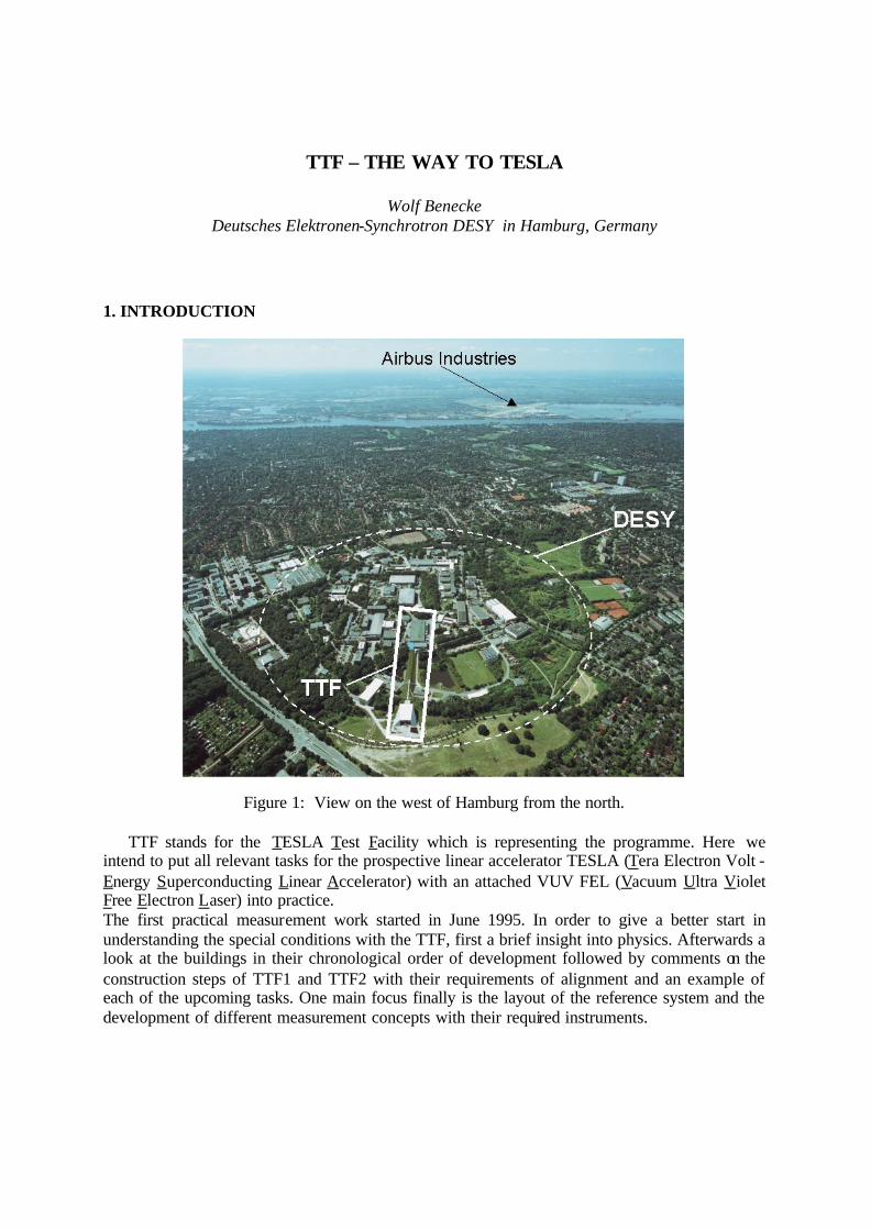
Figure 1: View on the west of Hamburg from the north.
TTF stands for the TESLA Test Facility which is representing the programme. Here we intend to put all relevant tasks for the prospective linear accelerator TESLA (Tera Electron Volt - Energy Superconducting Linear Accelerator) with an attached VUV FEL (Vacuum Ultra Violet Free Electron Laser) into practice. The first practical measurement work started in June 1995. In order to give a better start in understanding the special conditions with the TTF, first a brief insight into physics. Afterwards a look at the buildings in their chronological order of development followed by comments on the construction steps of TTF1 and TTF2 with their requirements of alignment and an example of each of the upcoming tasks. One main focus finally is the layout of the reference system and the development of different measurement concepts with their required instruments.
2. SOME PHYSICS
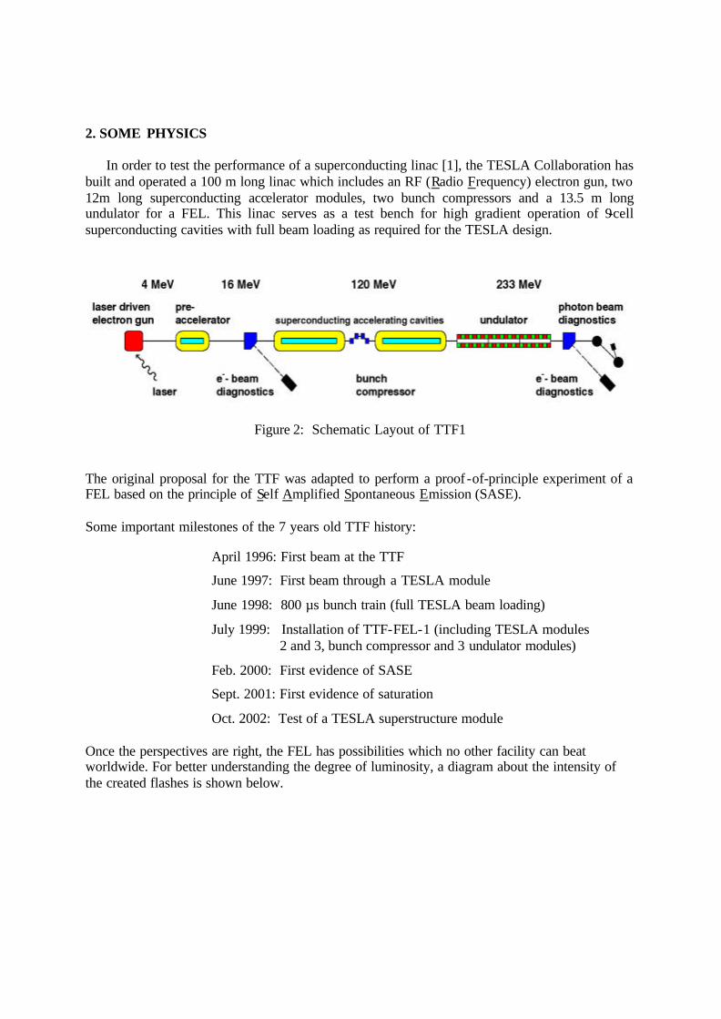
In order to test the performance of a superconducting linac [1], the TESLA Collaboration has built and operated a 100 m long linac which includes an RF (Radio Frequency) electron gun, two 12m long superconducting accelerator modules, two bunch compressors and a 13.5 m long undulator for a FEL. This linac serves as a test bench for high gradient operation of 9-cell superconducting cavities with full beam loading as required for the TESLA design.
Figure 2: Schematic Layout of TTF1 The original proposal for the TTF was adapted to perform a proof -of-principle experiment of a FEL based on the principle of Self Amplified Spontaneous Emission (SASE). Some important milestones of the 7 years old TTF history:
April 1996: First beam at the TTF
June 1997: First beam through a TESLA module
June 1998: 800 µs bunch train (full TESLA beam loading)
July 1999: Installation of TTF-FEL-1 (including TESLA modules 2 and 3, bunch compressor and 3 undulator modules)
Feb. 2000: First evidence of SASE
Sept. 2001: First evidence of saturation
Oct. 2002: Test of a TESLA superstructure module Once the perspectives are right, the FEL has possibilities which no other facility can beat worldwide. For better understanding the degree of luminosity, a diagram about the intensity of the created flashes is shown below.
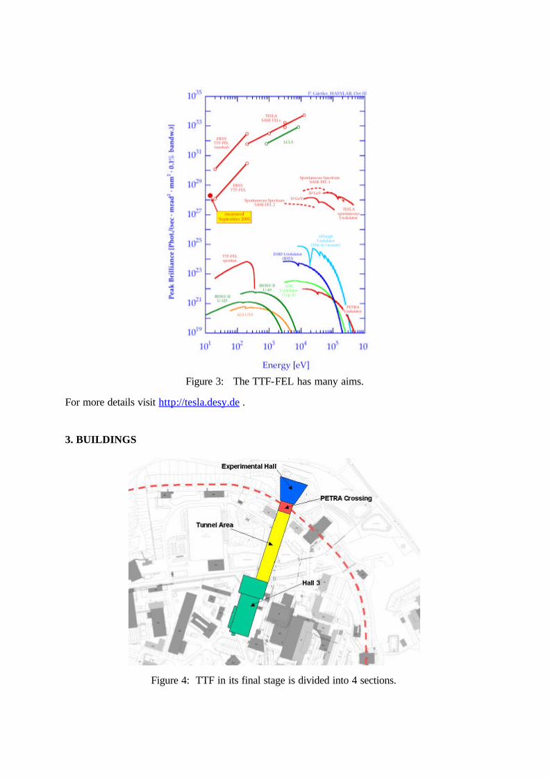
Figure 3: The TTF-FEL has many aims.
For more details visit http://tesla.desy.de . 3. BUILDINGS
Figure 4: TTF in its final stage is divided into 4 sections.
3.1 Hall 3
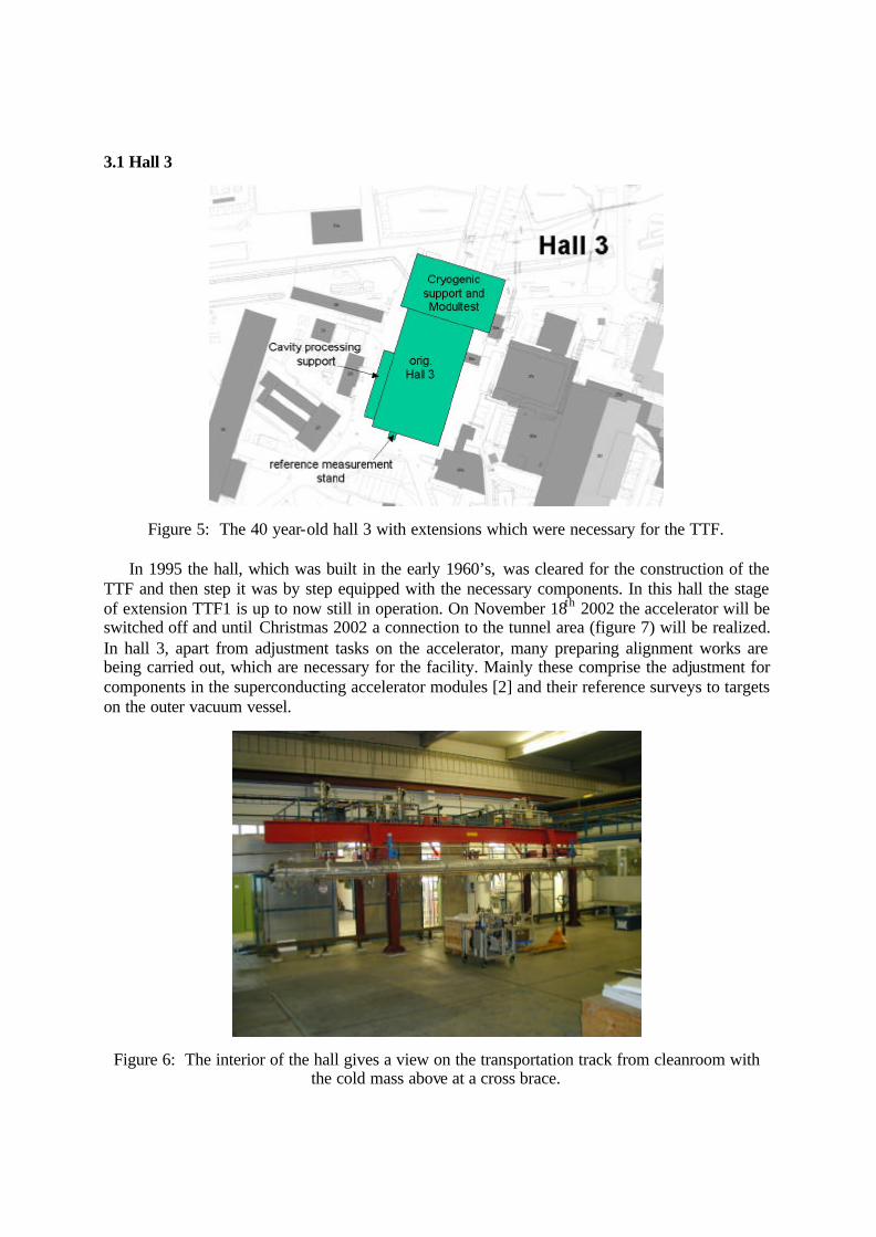
Figure 5: The 40 year-old hall 3 with extensions which were necessary for the TTF.
In 1995 the hall, which was built in the early 1960’s, was cleared for the construction of the TTF and then step it was by step equipped with the necessary components. In this hall the stage of extension TTF1 is up to now still in operation. On November 18th 2002 the accelerator will be switched off and until Christmas 2002 a connection to the tunnel area (figure 7) will be realized. In hall 3, apart from adjustment tasks on the accelerator, many preparing alignment works are being carried out, which are necessary for the facility. Mainly these comprise the adjustment for components in the superconducting accelerator modules [2] and their reference surveys to targets on the outer vacuum vessel.
Figure 6: The interior of the hall gives a view on the transportation track from cleanroom with the cold mass above at a cross brace.

3.2 Tunnel Area
Figure 7: The tunnel turns out to be the most important section.
In 1999 a tunnel in halfpipe-construction method was built about to hall 3. The tunnel is slightly longer than 150 meters and presents a 1:1 section of the future project TESLA into which as many as possible of the later -on needed components for the TESLA accelerator will be installed and will to be tested in their functionality.
Figure 8: October 2002 - In the tunnel the bases are ready for frames and components.
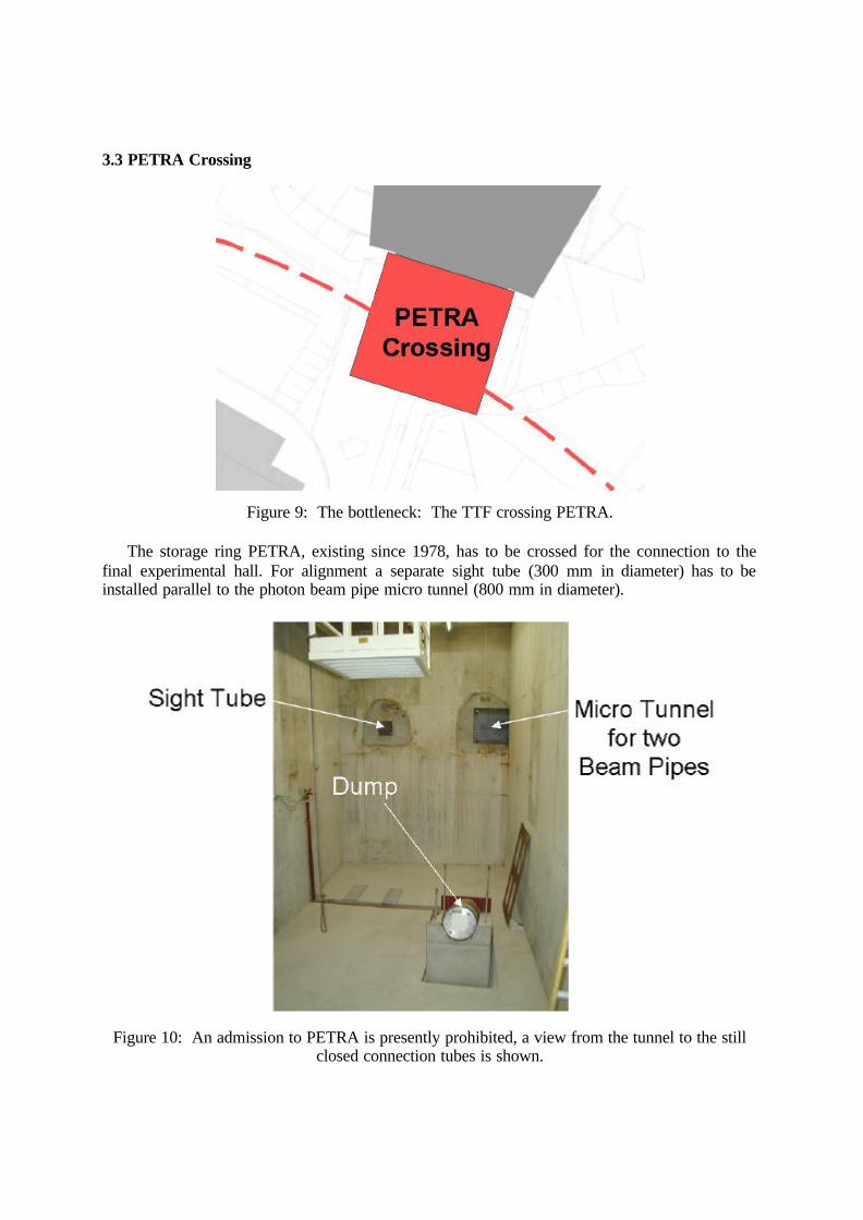
3.3 PETRA Crossing
Figure 9: The bottleneck: The TTF crossing PETRA.
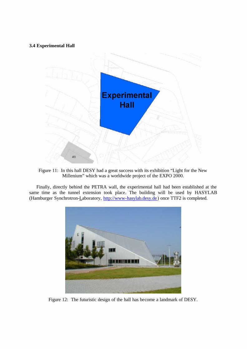
The storage ring PETRA, existing since 1978, has to be crossed for the connection to the final experimental hall. For alignment a separate sight tube (300 mm in diameter) has to be installed parallel to the photon beam pipe micro tunnel (800 mm in diameter).
Figure 10: An admission to PETRA is presently prohibited, a view from the tunnel to the still closed connection tubes is shown.
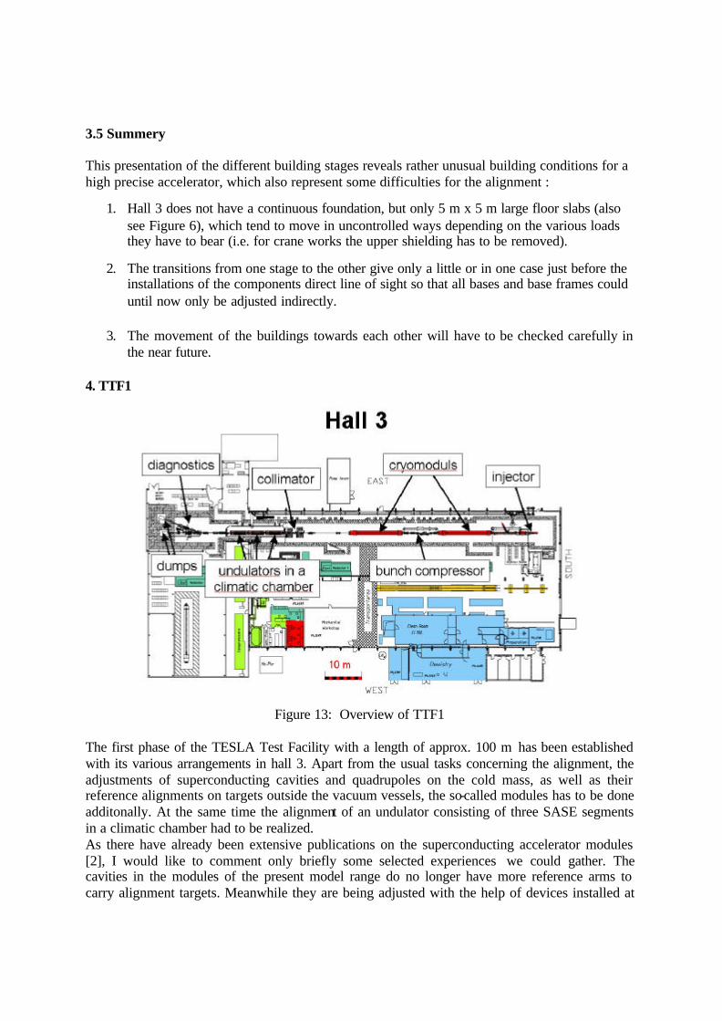
3.4 Experimental Hall
Figure 11: In this hall DESY had a great success with its exhibition “Light for the New Millenium” which was a worldwide project of the EXPO 2000.
Finally, directly behind the PETRA wall, the experimental hall had been established at the
same time as the tunnel extension took place. The building will be used by HASYLAB (Hamburger Synchrotron-Laboratory, http://www-hasylab.desy.de ) once TTF2 is completed.
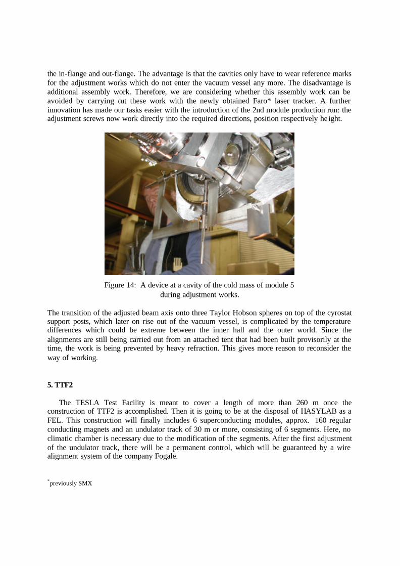
Figure 12: The futuristic design of the hall has become a landmark of DESY.
3.5 Summery This presentation of the different building stages reveals rather unusual building conditions for a high precise accelerator, which also represent some difficulties for the alignment :
1. Hall 3 does not have a continuous foundation, but only 5 m x 5 m large floor slabs (also see Figure 6), which tend to move in uncontrolled ways depending on the various loads they have to bear (i.e. for crane works the upper shielding has to be removed).
2. The transitions from one stage to the other give only a little or in one case just before the
installations of the components direct line of sight so that all bases and base frames could until now only be adjusted indirectly.
3. The movement of the buildings towards each other will have to be checked carefully in the near future.
4. TTF1
Figure 13: Overview of TTF1
The first phase of the TESLA Test Facility with a length of approx. 100 m has been established with its various arrangements in hall 3. Apart from the usual tasks concerning the alignment, the adjustments of superconducting cavities and quadrupoles on the cold mass, as well as their reference alignments on targets outside the vacuum vessels, the so-called modules has to be done additonally. At the same time the alignment of an undulator consisting of three SASE segments in a climatic chamber had to be realized. As there have already been extensive publications on the superconducting accelerator modules [2], I would like to comment only briefly some selected experiences we could gather. The cavities in the modules of the present model range do no longer have more reference arms to carry alignment targets. Meanwhile they are being adjusted with the help of devices installed at
the in-flange and out-flange. The advantage is that the cavities only have to wear reference marks for the adjustment works which do not enter the vacuum vessel any more. The disadvantage is additional assembly work. Therefore, we are considering whether this assembly work can be avoided by carrying out these work with the newly obtained Faro* laser tracker. A further innovation has made our tasks easier with the introduction of the 2nd module production run: the adjustment screws now work directly into the required directions, position respectively he ight.
Figure 14: A device at a cavity of the cold mass of module 5 during adjustment works.
The transition of the adjusted beam axis onto three Taylor Hobson spheres on top of the cyrostat support posts, which later on rise out of the vacuum vessel, is complicated by the temperature differences which could be extreme between the inner hall and the outer world. Since the alignments are still being carried out from an attached tent that had been built provisorily at the time, the work is being prevented by heavy refraction. This gives more reason to reconsider the way of working. 5. TTF2
The TESLA Test Facility is meant to cover a length of more than 260 m once the construction of TTF2 is accomplished. Then it is going to be at the disposal of HASYLAB as a FEL. This construction will finally includes 6 superconducting modules, approx. 160 regular conducting magnets and an undulator track of 30 m or more, consisting of 6 segments. Here, no climatic chamber is necessary due to the modification of the segments. After the first adjustment of the undulator track, there will be a permanent control, which will be guaranteed by a wire alignment system of the company Fogale. *previously SMX
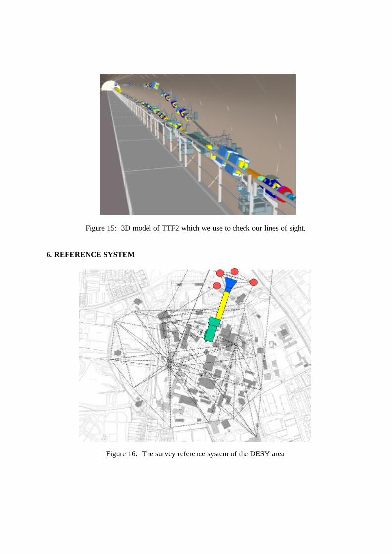
Figure 15: 3D model of TTF2 which we use to check our lines of sight. 6. REFERENCE SYSTEM
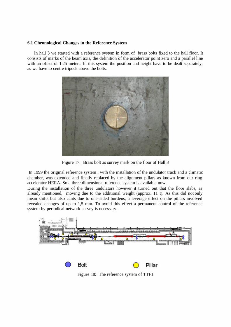
Figure 16: The survey reference system of the DESY area
6.1 Chronological Changes in the Reference System
In hall 3 we started with a reference system in form of brass bolts fixed to the hall floor. It consists of marks of the beam axis, the definition of the accelerator point zero and a parallel line with an offset of 1.25 meters. In this system the position and height have to be dealt separately, as we have to centre tripods above the bolts.
Figure 17: Brass bolt as survey mark on the floor of Hall 3
In 1999 the original reference system , with the installation of the undulator track and a climatic chamber, was extended and finally replaced by the alignment pillars as known from our ring accelerator HERA. So a three dimensional reference system is available now. During the installation of the three undulators however it turned out that the floor slabs, as already mentioned, moving due to the additional weight (approx. 11 t). As this did not only mean shifts but also cants due to one-sided burdens, a leverage effect on the pillars involved revealed changes of up to 1,5 mm. To avoid this effect a permanent control of the reference system by periodical network survey is necessary.
Figure 18: The reference system of TTF1
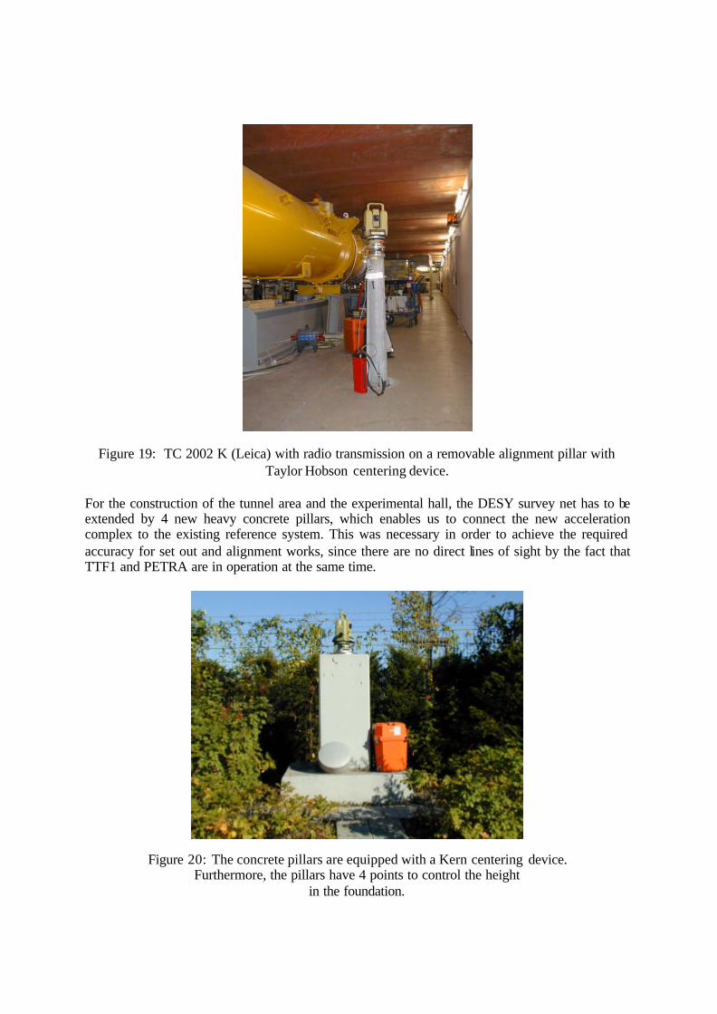
Figure 19: TC 2002 K (Leica) with radio transmission on a removable alignment pillar with Taylor Hobson centering device.
For the construction of the tunnel area and the experimental hall, the DESY survey net has to be extended by 4 new heavy concrete pillars, which enables us to connect the new acceleration complex to the existing reference system. This was necessary in order to achieve the required accuracy for set out and alignment works, since there are no direct lines of sight by the fact that TTF1 and PETRA are in operation at the same time.
Figure 20: The concrete pillars are equipped with a Kern centering device. Furthermore, the pillars have 4 points to control the height
in the foundation.
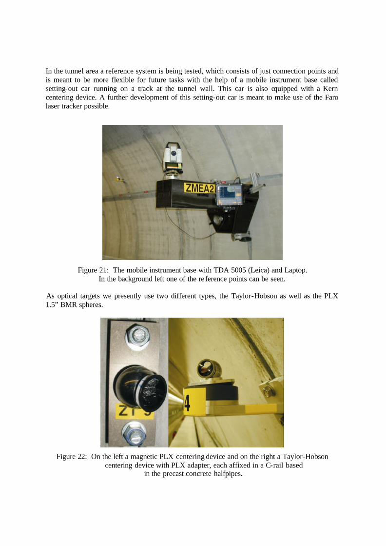
In the tunnel area a reference system is being tested, which consists of just connection points and is meant to be more flexible for future tasks with the help of a mobile instrument base called setting-out car running on a track at the tunnel wall. This car is also equipped with a Kern centering device. A further development of this setting-out car is meant to make use of the Faro laser tracker possible.
Figure 21: The mobile instrument base with TDA 5005 (Leica) and Laptop. In the background left one of the re ference points can be seen.
As optical targets we presently use two different types, the Taylor-Hobson as well as the PLX 1.5” BMR spheres.
Figure 22: On the left a magnetic PLX centering device and on the right a Taylor-Hobson centering device with PLX adapter, each affixed in a C-rail based
in the precast concrete halfpipes.
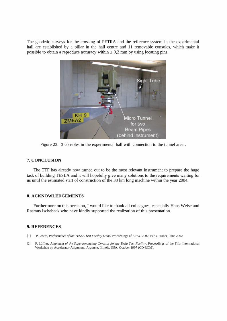
The geodetic surveys for the crossing of PETRA and the reference system in the experimental hall are established by a pillar in the hall centre and 11 removable consoles, which make it possible to obtain a reproduce accuracy within ± 0,2 mm by using locating pins.
Figure 23: 3 consoles in the experimental hall with connection to the tunnel area . 7. CONCLUSION
The TTF has already now turned out to be the most relevant instrument to prepare the huge task of building TESLA and it will hopefully give many solutions to the requirements waiting for us until the estimated start of construction of the 33 km long machine within the year 2004. 8. ACKNOWLEDGEMENTS
Furthermore on this occasion, I would like to thank all colleagues, especially Hans Weise and Rasmus Ischebeck who have kindly supported the realization of this presentation. 9. REFERENCES [1] P.Castro, Performance of the TESLA Test Facility Linac, Proceedings of EPAC 2002, Paris, France, June 2002 [2] F. Löffler, Alignment of the Superconducting Cryostat for the Tesla Test Facility, Proceedings of the Fifth International
Workshop on Accelerator Alignment, Argonne, Illinois, USA, October 1997 (CD-ROM).