ttu01/v35 ttu01/x21 ttu01/449 ttu01/530 … the 192-digit time-slots are ds0-channelized, the fs...
TRANSCRIPT

TTU01/V35 DS1/V.35 Interface TTU01/X21 DS1/X.21 Interface TTU01/449 DS1/RS449 (V.36) Interface TTU01/530 DS1/RS530 Interface
DS1 CSU/DSU Unit DS1/E1 Standalone rack mountable series


Table of Contents
i
Chapter 1. Introduction ………………………..….…. 1 1.1 Functional Description ……………………………….… 1
1.2 Typical System Application ……………………………. 3
1.3 Technical Specifications …………………………..….... 10
Chapter 2. Installation ………………..……………... 15 2.1 General ………………………………………………..... 15
2.2 Site Preparation ……………………………….……..…. 15
2.3 Mechanical Assembly ……………………..………….... 15
2.4 Electrical Installation ………………………………...…. 15
2.5 Dip Switches and Jumper Settings ….….……..………… 19
Chapter 3. Operation ………………………….….….. 21 3.1 General …………………………………………..……... 21
3.2 Controls and Indicators ………………………...………. 21
3.3 Operating Procedure …………………………..………... 24
Chapter 4. Tests And Diagnostics …………….….….. 25 4.1 General ………………………………………….……… 25
4.2 Loopback Tests ………………………………….……... 25
4.3 Bit Error Rate Tester …………………………….……... 25
4.4 Local Analog Loopback ……………………….……….. 26
4.5 Local Digital Loopback ……………………….…..……. 27
4.6 Remote Loopback ……………………………..…..……. 28

Table of Contents
ii
Appendix A. Dip Switch Setting Summary …….…… 29 A.1 All Dip Switching Functional Description ……….……. 29
A.2 Dip Sw1 Time Slot 0 To 7 Setting ……………….……. 30
A.3 Dip Sw2 Time Slot 8 To 15 Setting …………………… 31
A.4 Dip Sw3 Time Slot 16 To 23 Setting …………….……. 32
A.5 Dip Sw4 Line Build Out Setting ………………….….... 33
A.6 Dip Sw5 Parameter Group 1 Setting …………….….…. 34
A.7 Dip Sw6 Parameter Group 2 Setting …………….…….. 35
A.8 Dip Sw7 Line Impedance Setting ……………….…….. 35
A.9 Clock Mode Description ……………………….……… 36
Appendix B. Interface Specification …………...……. 37 B.1 DS1 Line Connector ……………………………..……. 37
B.2 X.21 User Data Channel Connector ……………..….…. 39
B.3 V.35 User Data Channel Connector ……………..….…. 40
B.4 RS-530 User Data Channel Connector …………..….…. 41
B.5 RS-530 To RS-449 Adapter Cable ………......….….….. 42
Appendix C. Rack Mounting Instructions …..……… 43
ii
Appendix D. ETU/TTU ET10/100 Interface Module . 45

Chapter 1. Introduction
1
1-1. Functional Description
The TTU-01 is a single port access unit for DS1, Fractional DS1 or Fractional cascade DS1 service.
The TTU-01 data channels support user-selectable transmission rates, which are integer multiples of 56 or 64kbps, up to a maximum 1.536Mbps (64K x 24), 1544Mbps for unframed, for a line attenuation of up to 36 dB on twisted pair.
The TTU-01 packs the data channels into DS1 link time slots in user-selected time slots, The unused time slots can insert IDLE code (In frame mode) or insert the receive side time slots data (In cascade mode).
The TTU-01 has three types of user-replaceable data channel modules, which provide the desired interface: V.35, X.21 or RS-530. RS-449 is supported by means of RS-530 to RS-449 adapter cable.
The TTU-01 fully meets all of the DS1 specifications including ITU G.703, G.704, G.706, G.823, and ANSI T1.403-1995.
The TTU-01 features V.54 diagnostic capabilities for performing local loopback and remote digital loopback. The operator at either end of the line may test both the TTU-01 and the line in the digital loopback mode. The loopback is controlled by either a manual switch or by the DTE interface for V.35 and RS-530.
Chapter 1. Introduction
2
A front panel switch generates an internal 511 bit pseudo random test pattern, according to CCITT, for direct end-to-end integrity testing. The Err indicator flashes for each bit error detected.
Multiple clock source selection provides maximum flexibility in connecting both the DS1 and user interface. The DS1 link may be clocked from the recovered receive clock, from user data port, or from the internal oscillator.
The TTU-01 user interface has five clocking modes:
Mode 0 (DCE 1): DCE interface. The TTU-01 provides the transmit and receive clocks (Recovered timing) to the equipment connected to the data channel.
Mode 1 (DCE 2): DCE interface. The TTU-01 provides the transmit and receive clocks (Internal oscillator timing) to the equipment connected to the data channel.
Mode 2 (DTE 1): DTE interface. The TTU-01 data channel accepts the user transmit clock and provides a receive clock (Recovered timing) to the equipment connected to the data channel.
Mode 3 (DTE 2): DTE interface. The TTU-01 data channel accepts the user transmit clock (from ETC pin) and receive clock (from ERC pin) provided by the equipment connector to the data channel.
Mode 4 (DTE 3): DTE interface. The TTU-01 data channel accepts the user transmit and receive clock (All from ETC pin) provided by the equipment connector to the data channel.

Chapter 1. Introduction
3
The TTU-01 operates from 115VAC, 230VAC or -48VDC. The unit is built in a compact case that can be placed on desk tops or shelves or installed, by means of an optional adapter, in a 19” rack.
1-2. Typical System Applications General
In a typical application (Figure 1-1), the TTU-01 is used to connect the synchronous user data channel to the serving central office over a DS1 line.
Figure 1-1 Point-to-Point Application
The fractional DS1 data service is based on the assumption that the user data rate is a fraction of the available DS1 bandwidth, in multiples of 56K or 64K.
DS1 signal structure
The DS1 line operates at a nominal rate of 1.544Mbps. The data transferred over the DS1 line is organized into frames, with each DS1 frame containing 193 bits. The 193 bits consist of 24 time slots of eight bits each, that carry the data payload, and one F-bit.
n x 56kbps HostHost n x 56kbps
TTU-01Point-to-point
T1Transmission
Facilities
TTU-01 Point-to-point
CTC CTC
Chapter 1. Introduction
4
DS1 transmission utilizes two main types of framing: Super Frame (SF)(D4) and Extended Super Frame (ESF). Framing is necessary in order for equipment receiving the DS1 signal to be able to identify and extract the individual channels.
Superframe format (SF) (D4)
A super frame consists of twelve consecutive frames. The SF format is a structure in which the F bits are used for framing only. In the SF format, the F bits are divided into two groups:
Terminal Framing (Ft) bits that are used to identify frame boundaries.
Signaling Frame (Fs) bits that are used to identify super frame boundaries. When the 192-digit time-slots are DS0-channelized, the Fs bits are also used to identify the signaling frames.
Extended superframe format (ESF)
An extended super frame consists of twenty-four frames. The ESF used the F bits for the following functions:
A 2-kbit/s frame pattern sequence (FPS): The FPS is used to identify the frame and the extended super frame boundaries. When the 192-information-digit time-slots are channelized, the FPS is used to identify the signaling frames.
A 4-kbit/s data link (DL): The ESF DL is for carrying performance information and control signals.
A 2-kbit/s cyclic redundancy check (CRC) channel: This channel carries a CRC-6 code.
Chapter 1. Introduction
5
DS1 line signal
The basic DS1 line signal is coded using the Alternate Mark Inversion (AMI) or B8ZS rule.
In the AMI format, “ones” are alternately transmitted as positive and negative pulses, whereas “zeros” are transmitted as a zero voltage level. AMI is not used in most 1.544 Mbps transmissions because of synchronization loss occurs during long strings of data zeros.
In the B8ZS format, a string of eight consecutive zeros is replaced with a substitute string of pulses containing an intentional bipolar violation. The B8ZS code substitutions provide high pulse density so that the receiving equipment is able to maintain synchronization with the received signal.
TTU-01 Capabilities DS1 link line coding
The TTU-01 supports two DS1 line codes:
AMI coding.
B8ZS coding.
DS1 framing formats
The TTU-01 supports three frame formats:
Unframed format.
SF (D4) format.
ESF format.

Chapter 1. Introduction
6
User data channel rates
The TTU-01 supports user data channel rates which are a multiple of 56 or 64kbps. For maximum flexibility, the TTU-01 supports data rates up to 1.544Mbps. The TTU-01 supports flexible time slot assignment, allowing the user to freely specify the selection of time slots.
User data channel interface The TTU-01 has three types of user data channel modules: V.35, X.21 and RS-530. The TTU-01 also supports RS-449 data channel via an interface adapter cable attached to the RS-530 channel module. The desired interface is achieved by installing the appropriate type of channel module in the TTU-01. For maximum flexibility, the TTU-01 supports data rates in multiples of 56Kbps or 64Kbps up to 1.544Mbps. The TTU-01 supports flexible time slot assignment, allowing the user to specify the selection of time slots used.
System Timing Considerations The TTU-01 has the flexibility to meet the timing requirements of various system configurations. The timing mode for the DS1 link and for the user channels are selected by the setting of DIP switches.

Chapter 1. Introduction
7
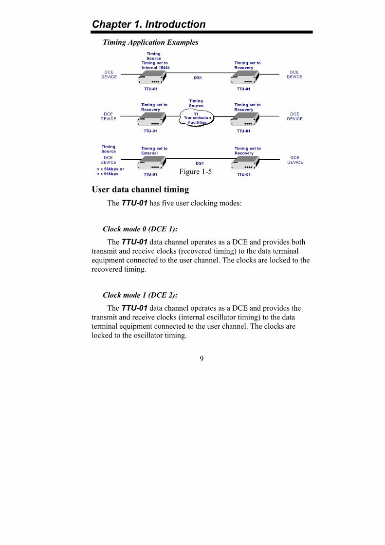
DS1 link timing The TTU-01 DS1 link receive path always operates on the receive clock. The TTU-01 recovers the receive clock from the received DS1 link data signal. The source of the TTU-01 DS1 link transmit clock can be selected by the user. The following DS1 link transmit timing modes are available, and application examples are shown in Figure 1-5:
Recovery timing:
The TTU-01 DS1 link transmit clock is locked to the recovered receive clock. This is usually the timing mode selected for network operation.
Figure 1-2 Recovery Timing
TCRC
TTU-01
PLL Rx
TxDS1
Chapter 1. Introduction
8
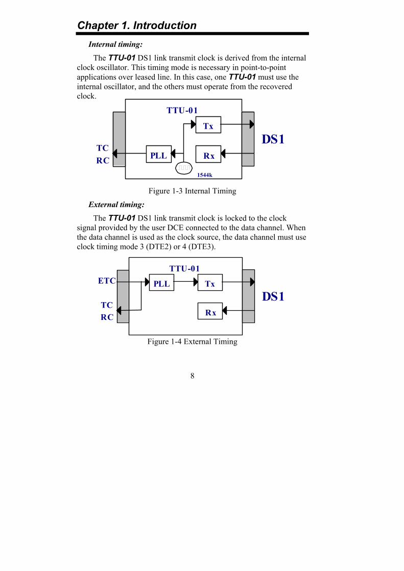
Internal timing:
The TTU-01 DS1 link transmit clock is derived from the internal clock oscillator. This timing mode is necessary in point-to-point applications over leased line. In this case, one TTU-01 must use the internal oscillator, and the others must operate from the recovered clock.
Figure 1-3 Internal Timing
External timing:
The TTU-01 DS1 link transmit clock is locked to the clock signal provided by the user DCE connected to the data channel. When the data channel is used as the clock source, the data channel must use clock timing mode 3 (DTE2) or 4 (DTE3).
Figure 1-4 External Timing
RCTC
TTU-01
PLL Rx
TxDS1
1544k
TCRC
ETCTTU-01
PLL
Rx
TxDS1
Chapter 1. Introduction
9
Timing Application Examples
Figure 1-5
User data channel timing The TTU-01 has five user clocking modes:
Clock mode 0 (DCE 1):
The TTU-01 data channel operates as a DCE and provides both transmit and receive clocks (recovered timing) to the data terminal equipment connected to the user channel. The clocks are locked to the recovered timing.
Clock mode 1 (DCE 2):
The TTU-01 data channel operates as a DCE and provides the transmit and receive clocks (internal oscillator timing) to the data terminal equipment connected to the user channel. The clocks are locked to the oscillator timing.
Timing set toInternal 1544k
DCEDEVICE
TTU-01TTU-01
CTC CTC
DCEDEVICE
Timing set toRecovery
DS1
TimingSource
Timing set toRecovery
DCEDEVICE
TimingSource
TTU-01
T1Transmission
Facilities
TTU-01
CTC CTC
DCEDEVICE
Timing set toRecovery
TimingSource
Timing set toExternal
n x 56kbps orn x 64kbps
DCEDEVICE
TTU-01TTU-01
CTC CTC
DCEDEVICE
Timing set toRecovery
DS1

Chapter 1. Introduction
10
Clock mode 2 (DTE 1):
The TTU-01 data channel supplies the receive clock to the synchronous DCE, and accepts a transmit clock from the DCE (from the ETC pin). The DCE must transmit data at the rate of the clock signal supplied by the TTU-01.
Clock mode 3 (DTE 2):
The TTU-01 data channel operates as a DTE and accepts both transmit clock (from the ETC pin) and receive clock (from the ERC pin) from the user equipment. NOTE: The X.21 data channel cannot be operated in clock timing mode 3 (DTE2).
Clock mode 4 (DTE 3):
The TTU-01 data channel operates as a DTE and accepts both transmit clock and receive clock (both from the ETC pin) from the user equipment.

Chapter 1. Introduction
11
1-3. TECHNICAL SPECIFICATIONS DS1 link
Framing -Unframed/Framed
-SF (D4) / ESF
Bit Rate 1.544 Mbps
Line Code -AMI
-B8ZS
Line Impedance -100 ohms
-Bridge (high Z)
Relative Receive Level 0 to –36dB
“Pulse” Amplitude Nominal 3.00V±20%
“Zero” Amplitude ±0.15V
Transmit Frequency Tracking
Internal Timing
Loopback Timing
External Timing
±30 ppm
±50 ppm
±100 ppm
Jitter Performance According to CCITT G.823
Complies With CCITT G.703, G.704, G.706, G.823 and ANSI T1.403
Interface Connectors -15-pin, D-type Female
-BNC
-Bantam

Chapter 1. Introduction
12
User Data Channels Interfaces Type -V.35
-X.21 -V.35 -RS-449(via adapter cable)
Interface Connectors V.35 Interface X.21 Interface RS-530 Interface RS-449 Interface
34 pin, Female 15 pin, D-type Female 25 pin, D-type Female 37 pin, D-type Male(via adapter cable)
Line Code NRZ Data Rate Unframe: 1.544 Mbps
Frame: n×56kbps or n×64kbps where n equal 1 to 24
Clock Modes Clock Mode 0 (DCE1) Receive and transmit clock (recovered) to the
synchronous DTE Clock Mode 1 (DCE2) Receive and transmit clock (internal
oscillator) to the synchronous DTE Clock Mode 2 (DTE1) Receive clock to the synchronous, and
transmit clock from the synchronous device Clock Mode 3 (DTE2) Receive and transmit clock from the
synchronous DCE (from ETC and ERC pin ) Clock Mode 4 (DTE3) Receive and transmit clock from the
synchronous DCE (all form ETC pin). Control Signals -CTS constantly ON
-DSR constantly ON, except during test loops -DCD constantly ON, except during signal loss
Time slot allocation User defined

Chapter 1. Introduction
13
Diagnostics
Test Switches/Diagnostics -Digital local loopback -Analog local loopback -Digital remote loopback -Test pattern
LED indicators
PWR Green Power TD Yellow Transmit data RD Yellow Receive data RTS Yellow Request to sent DCD Yellow Data carrier detect Tx CLK Loss
Red Transmit clock loss
Red Alarm Red DS1 link signal loss Sync Loss Red DS1 link sync loss Yel Alarm Red DS1 link yellow alarm Err Red Bit errors Test Red Loopback and pattern test
Physical
Height: 45 mm Width: 195 mm Depth: 255 mm Weight: 1.5 kg

Chapter 1. Introduction
14
Power supply
Voltage 115 or 230 VAC±10% -48VDC (-42 to -54VDC)
Frequency 47 to 63 Hz for AC power Power consumption 20 Watts Fuse 0.1A slow blow for 230 VAC
0.2A slow blow for 115 VAC 0.5A slow blow for -48 VDC
Environment
Temperature 0-50C / 32-122F Humidity 0 to 90% non-condensing

Chapter 2. Installation
15
2-1. GENERAL This chapter provides detailed instructions for mechanical installation of the TTU-01. Following the completion of installation, please refer to Chapter 3 for operating information.
2-2. SITE PREPARATION Install the TTU-01 within reach of an easily accessible grounded AC outlet. The outlet should be capable of furnishing 115 VAC or 230 VAC (depending on rated voltage of unit). Allow at least 10 cm (4 inches) clearance at the rear of the TTU-01 for signal lines and interface cables.
2-3. MECHANICAL ASSEMBLY The TTU-01 is designed for tabletop or bench installation, and is delivered completely assembled. No provisions are made for bolting the TTU-01 to the tabletop. The unit may also be mounted singularly or in pairs within an EIA 19 inch rack via an optional rack mounting kit.
2-4. ELECTRICAL INSTALLATION 2-4-1. Power connection
AC power is supplied to the TTU-01 through a standard IEC receptacle. (Refer to Figure 2-1) The TTU-01 should always be grounded through the protective earth lead of the power cable.
The line fuse is located in an integral-type fuse holder on the rear panel. Make sure that only fuses of the required rating are used for replacement. Do not use repaired fuses or short-circuit the fuse holder. Always disconnect the power cable before removing or replacing the fuse.
Chapter 2. Installation
16
2-4-2. Rear panel connectors:
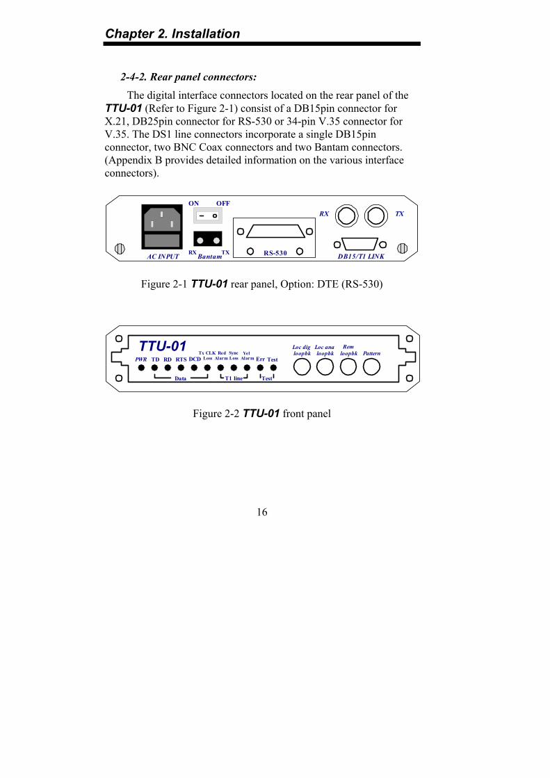
The digital interface connectors located on the rear panel of the TTU-01 (Refer to Figure 2-1) consist of a DB15pin connector for X.21, DB25pin connector for RS-530 or 34-pin V.35 connector for V.35. The DS1 line connectors incorporate a single DB15pin connector, two BNC Coax connectors and two Bantam connectors. (Appendix B provides detailed information on the various interface connectors).
Figure 2-1 TTU-01 rear panel, Option: DTE (RS-530)
Figure 2-2 TTU-01 front panel
AC INPUT DB15/T1 LINK
RX TX
Bantam
ON OFF
RS-530RX TX
TTU-01
Data T1 line Test
PWR TD RD RTS DCD LossTx CLK
AlarmRed
Alarm ErrLossSync
Testloopbk loopbk loopbkLoc dig Loc ana Rem
PatternYel

Chapter 2. Installation
17
DS1 Line side
DB-15 Connector
The pin assignments for the DB-15 connector are as follows:
Pin: Function: 1 TTIP (Transmit data out) 9 TRING (Transmit data out) 3 RTIP (Receive data in)
11 RRING (Receive data in)
BNC coax connector
Two BNC coax connectors marked RX and TX serve the same function as the DS1 line DB15 connector.
Bantam connector
Two BANTAM connectors marked RX and TX serve the same function as the DS1 line DB15 connector.
NOTE: Only one set of the above DS1 link connectors may be used at a time.
Data port side
V.35 interface connector
The V.35 connector utilizes standard pin-out. The three test pins have been chosen for loops and test. For applications using an V.35 interface, clock mode is selected DTE2, connect the ERC input clock to pins Z(A) and BB(B).
Chapter 2. Installation
18
X.21 interface connector
For applications using an X.21 interface external clock (Clock mode select DTE1 or DTE3), connect the input clock to pins 7(A) and 14(B) of the 15-pin connector.
RS-530 interface connector
The RS-530 connector utilizes standard pin-out. The three test pins have been chosen for loops and test. For applications using an RS-530 interface, clock mode is selected DTE2, connect the ERC input clock to pins 20(A) and 23(B).
RS-449 interface connector
Appendix B-5 describes the cabling connection between the RS-530 interface and the RS-449.
Cable and Termination
Use a shielded twisted pair cable between the TTU-01 and the DTE device. The receivers on the TTU-01 are 100 Ohm terminated (For X.21 and RS-530). If problems are encountered with the connection to the DTE interface, make sure that the DTE interface is terminated correctly.

Chapter 2. Installation
19
2-5. Dip Switches and Jumper Settings 2-5-1. Caution
To avoid accidental electric shock, be sure to disconnect the TTU-01 power cord before opening the cover. Access inside the equipment is only permitted only to authorized and qualified service personnel.
2-5-2. Procedure
a. Turn power OFF, Disconnect the power cord from the AC outlet.
b. Loosen the screws at the left/right of the rear panel.
c. Remove the PCB.
d. Adjust the DIP switches and jumpers as required, according to table 2-1. (Appendix A describes the DIP switch functions).
e. Carefully replace the PCB and tighten the screws.

Chapter 2. Installation
20
Table 2-1 Item Function Possible Settings Set Place Factory Setting
1 Set the active timeslot TS0 to TS23 random setting DIPSW1-1 to DIPSW3-8 TS0 to TS3
2 Set the line build out 0-155 to 533-655 feet,-7.5,-15,-22.5db DIPSW4-1 to DIPSW4-3 0-155 feet
3 Set the timing mode M0 (MODE0) to M4 (MODE4) DIPSW5-1 to DIPSW5-3 MODE0 (DCE1)
4 Set the DS1 line code B8ZS or AMI DIPSW5-4 B8ZS
5 Set the DS1 frame format SF (D4) or ESF DIPSW5-5 SF (D4)
6 Set the DS1 line idle code FF (0xFF) or 7E (0x7E) DIPSW5-7 0xFF
7 Select the N64K or N56K N64 or N56 DIPSW5-8 N64
8 Set the DS1 jitter DIS (disable) or ENA (enable) DIPSW6-1 Enable
9 Set the DS1 jitter place RX or TX side DIPSW6-2 RX side
10 Set the DS1 jitter length 32 or 128 bits DIPSW6-3 32 bits
11 Set multiplex (cascade) function DIS (disable) or ENA (enable) DIPSW6-4 Disable
12 Set in multiplex signaling passthrough MM1 (nonpass) or MM2 (passthrough) DIPSW6-5 Nonpass
13 Set data port loopback test function DIS (disable) or ENA (enable) DIPSW6-7 Disable
14 Set front panel switch function DIS (disable) or ENA (enable) DIPSW6-8 Enable
15 Set the DS1 line impedance 100 Ohm or Bridge DIPSW7-1 to DIPSW7-5 100 Ohm
16 Set main board chassis ground DIS (disconnect) or CON (Connect) JP1 Connect
17 Set extern board chassis ground DIS (disconnect) or CON (Connect) JP1(On small PCB) Connect
Note: If the DTE does not provide the test pins for loopback test, the data port loopback test function must be always set to DIS (disable).

Chapter 3. Operation
21
3-1. General This chapter describes the TTU-01’s controls and indicators, explains the operating procedures, and supplies instructions for field strapping changes. Installation procedures (in Chapter 2) must be completed and checked before attempting to operate the TTU-01.
3-2. Controls and Indicators All controls (pushbutton switches) and LED indicators are located on the TTU-01 front panel. Depress a push-button to activate (turn ON) the corresponding control. Release the push-button to deactivate (turn OFF) the control.
The function of each pushbutton and indicator is described in Table 3-1 and Table 3-2 respectively.
Figure 3-1 TTU-01 Front Panel
TTU-01
Data T1 line Test
PWR TD RD RTS DCD LossTx CLK
AlarmRed
Alarm ErrLossSync
Testloopbk loopbk loopbkLoc dig Loc ana Rem
PatternYel

Chapter 3. Operation
22
Table 3-1 Control Functions Item Control Switch Function
1 Loc dig loopbk The local digital loopback switch causes the local TTU-01 to loop received data to its transmitter.
2 Loc ana loopbk The local analog loopback switch causes the local TTU-01 to loop transmitter output back to its receiver and send all “1” signal to DS1 link during local analog loopback activated. This loopback may also be activated from the DTE when the data port loopback test function is set to ENA (enable).
3 Rem loopbk The remote loopback switch causes the remote TTU-01 to loop received data to its transmitter. This loopback may also be activated from the DTE when the data port loopback test function is set to ENA (enable).
4 Pattern The pattern switch causes the TTU-01to send and receive a 511 test pattern. If errors are encountered, the Err LED indicator lights.

Chapter 3. Operation
23
Table 3-2 LED indicators Item Indicator Color Function
1 PWR Green ON when unit power is on.
2 TD Yellow ON when SPACE is being transmitted. Flashing when data is transmitted.
3 RD Yellow ON when SPACE is being received. Flashing when data is received.
4 RTS Yellow ON when terminal activates Request To Sent.
5 DCD Yellow ON when a valid receive signal is present.
6 Tx CLK Loss Red ON when transmitted clock is lost.
7 Red Alarm Red ON when received signal is lost.
8 Sync Loss Red ON when received frame sync is lost.
9 Yel Alarm Red ON when the DS1 link receives a yellow alarm.
10 Err Red ON when the Pattern switch is activated and has bit errors.
11 Test Red ON when the TTU-01 is in any loopback mode or Pattern is depressed.

Chapter 3. Operation
24
3-3. Operating Procedure The TTU-01 requires no operator attention once installed, except for occasional monitoring of the front panel indicators. Intervention is only required when:
(1) The TTU-01 has to be adapted to a new operational requirement.
(2) Diagnostic loops are required.
The TTU-01 is turned on when its AC power cord is connected to an AC power outlet and the power switch is turned to the ON position. The PWR indicator lights, indicating that the TTU-01 is on. Verify the TTU-01 is in operation by checking that the front panel LEDs match the following indicator conditions:
PWR: ON
TD: ON, OFF or Flashing
RD: ON, OFF or Flashing
RTS: ON
DCD: ON
Tx CLK Loss: OFF
Red Alarm: OFF
Sync Loss: OFF
Yel Alarm: OFF
Err: OFF
Test: OFF

Chapter 4. Tests And Diagnostics
25
4-1. General This chapter contains procedures for performing system diagnostic tests.
4-2. Loopback Tests The loop back test buttons (Loc dig loopbk, Loc ana loopbk and Rem loopbk) and the LED indicators built into the TTU-01 allow for rapid checking of the data terminal, TTU-01 and the DS1 line. Before testing the operation of the data system equipment and their line circuits, ensure that all units are turned on and are configured correctly.
4-3. Bit Error Rate Test When depressing the Pattern push-button switch, the Bit Error Rate Test (BERT) can be activated in any diagnostics test in which the test pattern transmitted is received by another TTU-01 (see Figure 4-1). When used opposite another TTU-01, either with the Pattern push-button switch depressed or with an external BERT transmitting the same pattern (V.52 511-bit), the complete link can be tested. If errors are encountered, the Err indicator LED will blink (for intermittent errors) or remain on continuously (for continuous errors).
Figure 4-1 BERT operation, with external BERT TTU-01 TTU-01
Tester
PatternGenerator
Pattern
PatternDepressed
ExternalBERT511
RCV
XMT
DS1Link

Chapter 4. Tests And Diagnostics
26
Figure 4-2 BERT operation, without external BERT
4-4. Local Analog Loopback The local analog loop back test is activated by depressing the “Loc ana loopbk” pushbutton. This test checks the performance of the TTU-01, the local data terminal, and the connections between them. It is performed separately at the local and the remote sites (see Figure 4-3). In local analog loopback, the transmit sends an all “1” signal to DS1 line.
Figure 4-3 Local analog loop back
TTU-01 TTU-01
PatternTester
Tester
Pattern
PatternGenerator
Generator
Pattern
PatternDepressed
PatternDepressed
DS1Link
TTU-01
XMTR
RCVR
Loc ana loopbkDepressed
DATATERMINAL
CLK
DATA
DATA
CLKX
"ones"
DS1Link

Chapter 4. Tests And Diagnostics
27
4-5. Local Digital Loopback The local digital loop back test is activated by depressing the “Loc dig loopbk” pushbutton. This test consists of looping the received DS1 data to the remote TTU-01. The test checks the performance of the local TTU-01, the remote TTU-01 and the connections between them (see Figure 4-4).
Figure 4-4 Local digital loop back
TTU-01 TTU-01
Tester
PatternGenerator
Pattern
PatternDepressed
Loc DigLoopbk
Depressed
DS1Link

Chapter 4. Tests And Diagnostics
28
4-6. Remote Loopback The remote loop back test is activated by depressing the “Rem loopbk” pushbutton. This test determines the performance both of the local and the remote TTU-01 units, as well as their interconnecting lines. The remote loopback test provides a loopback at the remote TTU-01 (see Figure 4-5).
In SF (D4) frame format, the remote line loop back uses the in-band control signal. The in-band control signals for remote line loopback are as follows:
Loop up code (Loopback ON): 10000.
Loop down code (Loopback OFF): 100.
In ESF frame format, the remote line loop back is controlled by the ESF Data link messages. The control signals for remote line loopback are as follows:
Loop up code (Loopback ON): 0000111011111111.
Loop down code (Loopback OFF): 0011100011111111.
Figure 4-5 Remote loop back
TTU-01 Remote TTU-01
Tester
PatternGenerator
Pattern
PatternDepressed
Rem LoopbkDepressed
DS1Link
Appendix A. DIP SW. Setting Summary
29
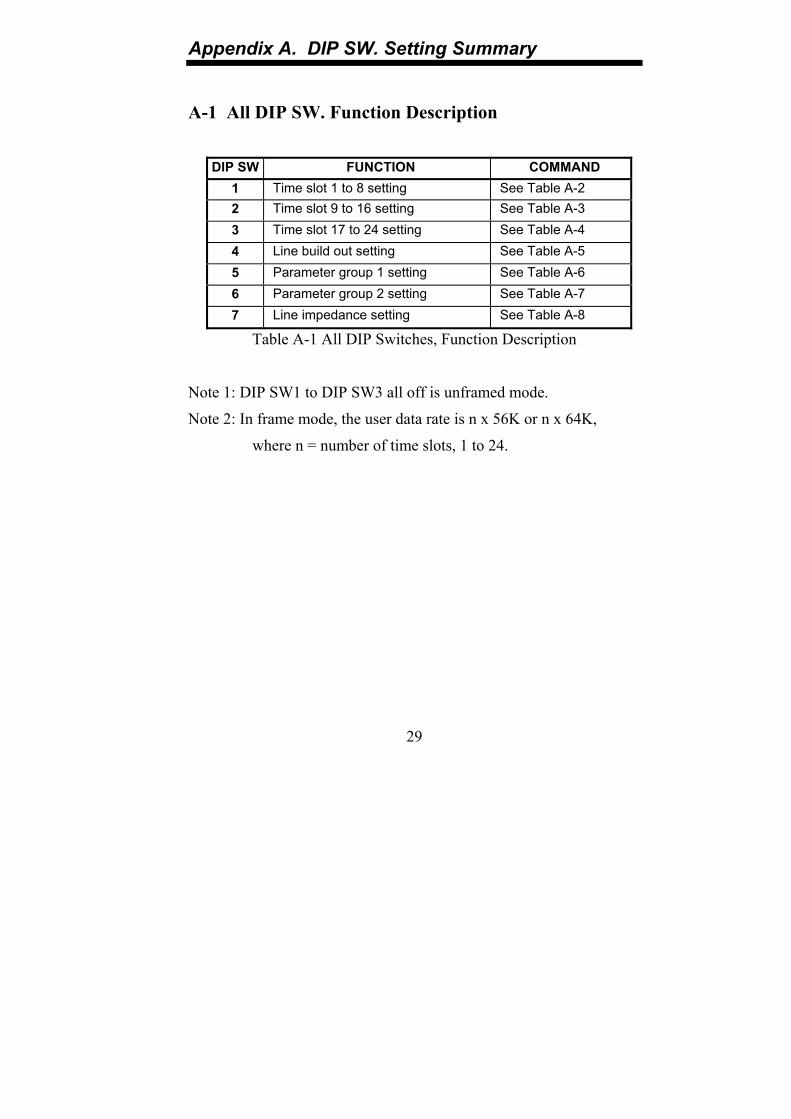
A-1 All DIP SW. Function Description
DIP SW FUNCTION COMMAND 1 Time slot 1 to 8 setting See Table A-2 2 Time slot 9 to 16 setting See Table A-3 3 Time slot 17 to 24 setting See Table A-4 4 Line build out setting See Table A-5 5 Parameter group 1 setting See Table A-6 6 Parameter group 2 setting See Table A-7 7 Line impedance setting See Table A-8
Table A-1 All DIP Switches, Function Description
Note 1: DIP SW1 to DIP SW3 all off is unframed mode.
Note 2: In frame mode, the user data rate is n x 56K or n x 64K,
where n = number of time slots, 1 to 24.

Appendix A. DIP SW. Setting Summary
30
A-2 DIP SW1 Time Slot 0 To 7 Setting
DIP SW1 STATE FUNCTION COMMAND -1 OFF Time slot 1 disable ON Time slot 1 enable
-2 OFF Time slot 2 disable ON Time slot 2 enable
-3 OFF Time slot 3 disable ON Time slot 3 enable
-4 OFF Time slot 4 disable ON Time slot 4 enable
-5 OFF Time slot 5 disable ON Time slot 5 enable
-6 OFF Time slot 6 disable ON Time slot 6 enable
-7 OFF Time slot 7 disable ON Time slot 7 enable
-8 OFF Time slot 8 disable ON Time slot 8 enable
Table A-2 DIP SW1 Time Slot 0 To 7 Setting

Appendix A. DIP SW. Setting Summary
31
A-3 DIP SW2 Time Slot 8 To 15 Setting
DIP SW2 STATE FUNCTION COMMAND -1 OFF Time slot 9 disable ON Time slot 9 enable
-2 OFF Time slot 10 disable ON Time slot 10 enable
-3 OFF Time slot 11 disable ON Time slot 11 enable
-4 OFF Time slot 12 disable ON Time slot 12 enable
-5 OFF Time slot 13 disable ON Time slot 13 enable
-6 OFF Time slot 14 disable ON Time slot 14 enable
-7 OFF Time slot 15 disable ON Time slot 15 enable
-8 OFF Time slot 16 disable ON Time slot 16 enable
Table A-3 DIP SW2 Time Slot 8 To 15 Setting

Appendix A. DIP SW. Setting Summary
32
A-4 DIP SW3 Time Slot 16 To 23 Setting
DIP SW3 STATE FUNCTION COMMAND -1 OFF Time slot 17 disable ON Time slot 17 enable Note 1
-2 OFF Time slot 18 disable ON Time slot 18 enable
-3 OFF Time slot 19 disable ON Time slot 19 enable
-4 OFF Time slot 20 disable ON Time slot 20 enable
-5 OFF Time slot 21 disable ON Time slot 21 enable
-6 OFF Time slot 22 disable ON Time slot 22 enable
-7 OFF Time slot 23 disable ON Time slot 23 enable
-8 OFF Time slot 24 disable ON Time slot 24 enable
Table A-4 DIP SW3 Time Slot 16 To 23 Setting
Note 1: In CAS mode, DIP SW3-1 must not be set to ON.
Appendix A. DIP SW. Setting Summary
33
A-5 DIP SW4 Line Build Out Setting
DIP SW4 STATE FUNCTION COMMAND -1,-2,-3 OFF OFF OFF 0 to 133 feet / 0dB
ON OFF OFF 133 to 266 feet
OFF ON OFF 266 to 399 feet
ON ON OFF 399 to 533 feet
OFF OFF ON 533 to 655 feet
ON OFF ON -7.5 dB
OFF ON ON -15 dB
ON ON ON -22.5 dB
-4 OFF Reserved ON Reserved
-5 OFF Reserved ON Reserved
-6 OFF Reserved ON Reserved
-7 OFF Reserved ON Reserved
-8 OFF Reserved ON Reserved
Table A-5 DIP SW4 Line Build Out Setting

Appendix A. DIP SW. Setting Summary
34
A-6 DIP SW5 Parameter Group 1 Setting
DIP SW5 STATE FUNCTION COMMAND -1,-2,-3 OFF OFF OFF Clock mode 0 (DCE1) See Table A-9
ON OFF OFF Clock mode 1 (DCE2)
OFF ON OFF Clock mode 2 (DTE1)
ON ON OFF Clock mode 3 (DTE2)
OFF OFF ON Clock mode 4 (DTE3)
ON OFF ON Reserved
OFF ON ON Reserved
ON ON ON Reserved
-4 OFF Line code: B8ZS
ON Line code: AMI
-5 OFF Frame mode: SF (D4)
ON Frame mode: ESF
-6 OFF Reserved
ON Reserved
-7 OFF Idle code: Mark (0xFF)
ON Idle code: Flag (0x7E)
-8 OFF Data channel rate: n×64
ON Data channel rate: n×56
Table A-6 DIP SW5 Parameter Group 1 Setting

Appendix A. DIP SW. Setting Summary
35
A-7 DIP SW6 Parameter Group 2 Setting
DIP SW6 STATE FUNCTION COMMAND -1 OFF Jitter attenuator: Disable ON Jitter attenuator: Enable
-2 OFF Jitter place in: Received side ON Jitter place in: Transmitted side
-3 OFF Jitter buffer depth: 32 bits ON Jitter buffer depth: 128 bits
-4 OFF Multiplex (cascade): Disable ON Multiplex (cascade): Enable
-5 OFF Signaling: Non pass through ON Signaling: Pass through
-6 OFF Reserved ON Reserved
-7 OFF Data port loop back: Disable ON Data port loop back: Enable
-8 OFF Front panel loop back: Disable ON Front panel loop back: Enable
Table A-7 DIP SW6 Parameter Group 2 Setting
A-8 DIP SW7 Line Impedance Setting
DIP SW7 STATE FUNCTION COMMAND ALL OFF,OFF,ON,ON,OFF 100 ohm
1,2,3,4,5 OFF,OFF,OFF,OFF,OFF Bridge
Table A-8 DIP SW7 Line Impedance Setting
Appendix A. DIP SW. Setting Summary
36
A-9 Clock Mode Description
CLOCK DIPSW 5 DS1 LINE USER DATA PORT
MODE STATE TRANSMIT RECEIVE TRANSMIT -1 -2 -3 CLOCK CLOCK CLOCK
0 (DCE1)
OFF OFF OFF RECOVERY* RECOVERY Output to RC pin
RECOVERY Output to TC pin
1 (DCE2)
ON OFF OFF INTERNAL
OSCILLATOR
INTERNAL Output to RC pin
INTERNAL Output to TC pin
2 (DTE1)
OFF ON OFF EXTERNAL Locked at ETC pin
RECOVERY Output to RC pin
EXTERNAL Input from ETC pin
3 (DTE2)
ON ON OFF EXTERNAL Locked at ETC pin
EXTERNAL Input from ERC pin
EXTERNAL Input from ETC pin
4 (DTE3)
OFF OFF ON EXTERNAL Locked at ETC pin
EXTERNAL Input from ETC pin
EXTERNAL Input from ETC pin
Table A-9 Clock Mode Description
*Recovery timing is synonymous with loopback timing.

Appendix B. Interface Specifications
37
B-1. DS1 Line Connectors B-1.1 D-15 connector:
The DS1 link D-15 connector conforms to AT&T Pub 62411. The physical interface is a 15-pin female D-type connector.
Pin Designation Direction Function
1 TTIP From TTU-01 Transmit data
2 FG ↔ Frame ground
3 RTIP To TTU-01 Receive data
4 FG ↔ Frame ground
5 -- -- --
6 -- -- --
7 -- -- --
8 -- -- --
9 TRING From TTU-01 Transmit data
10 -- -- --
11 RRING To TTU-01 Receive data
12 -- -- --
13 -- -- --
14 -- -- --
15 -- -- --
Table B-1 DS1 D-15 connector pin assignment
Appendix B. Interface Specifications
38
B-1.2 BNC connectors:
Conn. Pin Designation Direction Function
Center TTIP From TTU-01 Transmit data TX Sleeve TRING ↔ Signal return
Center RTIP To TTU-01 Receive data RX
Sleeve RRING ↔ Signal return
Table B-2 DS1 BNC connector pin assignment
B-1.3 Bantam connectors:
Conn. Pin Designation Direction Function
Tip TTIP From TTU-01 Transmit data
Ring TRING ↔ Signal return
TX
Sleeve FG ↔ Frame ground
Tip RTIP To TTU-01 Receive data
Ring RRING ↔ Signal return
RX
Sleeve FG ↔ Frame ground
Table B-3 DS1 Bantam connector pin assignment

Appendix B. Interface Specifications
39
B-2. X.21 User Data Channel Connector When the TTU-01 is ordered with an X.21 interface, the physical interface is a 15-pin female D-type connector wired in accordance with Table B-4.
SIGNAL
FUNCTION
PIN CIRCUIT DIRECTION DESCRIPTION
Protective
Ground
1 Shield ↔ Chassis ground.
May be isolated from Signal Ground.
Signal
Ground
8 G ↔ Common signal ground.
Transmitted
Data
2
9
T(A)
T(B)
To TTU-01 Serial digital data from DTE.
Received
Data
4
11
R(A)
R(B)
Fm TTU-01 Serial digital data at the output of the TTU-01 receiver.
Request to
Sent
3
10
C(A)
C(B)
To TTU-01 An ON signal to the TTU-01 when data transmission is desired.
Data Carrier
Detect
5
12
I(A)
I(B)
Fm TTU-01 Constantly ON, except when a loss of the received carrier signal is detected.
Signal
Timing
6
13
S(A)
S(B)
Fm TTU-01 A transmit data rate clock for use by an external data source.
External Transmit
clock
7
14
B(A)
B(B)
To TTU-01 A serial data rate clock input from the data source.
-- 15 -- -- --
Table B-4 X.21 user data channel connector pin assignment

Appendix B. Interface Specifications
40
B-3. V.35 User Data Channel Connector When the TTU-01 is ordered with a V.35 interface, the physical interface is a 34-pin female M-type connector wired in accordance with Table B-5.
SIGNAL FUNCTION
PIN CIRCUIT DIRECTION DESCRIPTION
Protective Ground
A Frame ↔ Chassis ground. May be isolated from signal ground.
Signal Ground
B Signal Ground
↔ Common signal ground.
Transmitted Data
P S
TD(A) TD(B)
To TTU-01 Serial digital data from DTE.
Received Data
R T
RD(A) RD(B)
From TTU-01 Serial digital data at the output of the TTU-01 receiver.
Request to Sent
C RTS
To TTU-01 A ON signal to the TTU-01 when data transmission is desired.
Clear to Sent
D CTS
From TTU-01 Constantly ON.
Data Set Ready
E DSR
From TTU-01 Constantly ON, except during test loops.
Data Terminal Ready
H DTR
To TTU-01 Not used.
Data Carrier Detect
F DCD From TTU-01 Constantly ON, except when a loss of the received carrier signal is detected.
External Transmit clock
U W
ETC(A) ETC(B)
To TTU-01 A transmitted data rate clock input from the data source.
Transmit Clock
Y AA
TC(A) TC(B)
From TTU-01 A transmitted data rate clock for use by an external data source.
Receive Clock
V X
RC(A) RC(B)
From TTU-01 A received data rate clock for use by an external data source.
External Receive clock
Z BB
ERC(A) ERC(B)
To TTU-01 A received serial data rate clock input from the DTE.
Remote Loop back
HH RL To TTU-01 When on, commands TTU-01 into remote loop back, can disable by DIPSW.
Local Loop back
JJ LL To TTU-01 When on, commands TTU-01 into local loop back, can disable by DIPSW.
Test Indicator
KK TM From TTU-01 ON during any test mode
Table B-5 V.35 user data channel connector pin assignment

Appendix B. Interface Specifications
41
B-4. RS-530 User Data Channel Connector When the TTU-01 is ordered with an RS-530 interface, the physical interface is a 25-pin female D-type connector wired in accordance with Table B-6.
SIGNAL FUNCTION
PIN CIRCUIT DIRECTION DESCRIPTION
Protective Ground
1 Frame ↔ Chassis ground. May be isolated from signal ground.
Signal Ground
7 AB ↔ Common signal ground.
Transmitted Data
214
BA(A) BA(B)
To TTU-01 Serial digital data from DTE.
Received Data
316
BB(A) BB(B)
From TTU-01 Serial digital data at the output of the TTU-01 receiver.
Request to Sent
419
CA(A) CA(B)
To TTU-01 A ON signal to the TTU-01 when data transmission is desired.
Clear to Sent
513
CB(A) CB(B)
From TTU-01 Constantly ON.
Data Set Ready
622
CC(A) CC(B)
From TTU-01 Constantly ON, Except during test loops.
Data Terminal Ready
20 23
CD(A) CD(B)
To TTU-01 DTR not used, used for a received serial data rate clock input from the DTE.
Data CarrierDetect
810
CF(A) CF(B)
From TTU-01 Constantly ON, except when a loss of the received carrier signal is detected.
External Transmit clock
24 11
DA(A) DA(B)
To TTU-01 A transmitted data rate clock input from the data source.
Transmit Clock
15 12
DB(A) DB(B)
From TTU-01 A transmitted data rate clock for use by an external data source.
Receive Clock
17 9
DD(A) DD(B)
From TTU-01 A received data rate clock for use by an external data source.
Remote Loop back
21 RL To TTU-01 When on, commands TTU-01 into remote loop back, can disable by DIPSW.
Local Loop back
18 LL To TTU-01 When on, commands TTU-01 into local loop back, can disable by DIPSW.
Test Indicator
25 TM From TTU-01 ON during any test mode
Table B-6 RS-530 user data channel connector pin assignment

Appendix B. Interface Specifications
42
B-5. RS-530 To RS-449 Adapter Cable When the TTU-01 is ordered with a RS-449 interface, the physical interface is a 37-pin male D-type connector wired in accordance with Table B-7.
SIGNAL FUNCTION
RS-530 PIN
RS-449 PIN
RS-449 CIRCUIT
DESCRIPTION
Protective Ground
1 1 Frame Chassis ground. May be isolated from signal ground.
Signal Ground
7 19,20, 37
SG,RC, SC
Common signal ground.
Transmitted Data
2 14
4 22
SD(A) SD(B)
Serial digital data from DTE.
Received Data
3 16
6 24
RD(A) RD(B)
Serial digital data at the output of the TTU-01 receiver.
Request to Sent
4 19
7 25
RS(A) RS(B)
A ON signal to the TTU-01 when data transmission is desired.
Clear to Sent
5 13
9 27
CS(A) CS(B)
Constantly ON.
Data Set Ready
6 22
11 29
DM(A) DM(B)
Constantly ON, Except during test loops.
Data Terminal Ready
20 23
12 30
TR(A) TR(B)
DTR not used, used for a received serial data rate clock input from the DTE.
Data Carrier Detect
8 10
13 31
RR(A) RR(B)
Constantly ON, except when a loss of the received carrier signal is detected.
External Transmit clock
24 11
17 35
TT(A) TT(B)
A transmitted data rate clock input from the data source.
Transmit Clock
15 12
5 23
ST(A) ST(B)
A transmitted data rate clock for use by an external data source.
Receive Clock
17 9
8 26
RT(A) RT(B)
A received data rate clock for use by an external data source.
Remote Loop back
21 14 RL When on, sets TTU-01 into remote loop back, can disable by DIPSW.
Local Loop back
18 10 LL When on, sets TTU-01 into local loop back, can disable by DIPSW.
Test Indicator 25 18 TM ON during any test mode
Table B-7 RS-530 to RS-449 pin assignment

Appendix C. Rack Mounting Instructions
43
Optional Rack Mounting Kits All rack mount series units may be placed in a stand EIA 19 inch rack occupying one unit space by means of the optional rack mounting adapter kit. Units may be mounted singularly or in pairs side-by-side.
Single unit mounting kit:
Figure C-1. Single Unit Rack Mount
Using the four (4) supplied self-tapping sheet metal screws, attach the brackets to the main unit. The unit may be mounted on the left side (as shown) or on the right side at your discretion.

Appendix C. Rack Mounting Instructions
44
Dual Unit Mounting Kit:
Figure C-2. Dual Unit Rack Mount
Attach the brackets as shown with the supplied self-tapping sheet metal screws. Refer to the drawing below for unit connection.
Figure C-3. Dual Unit Detail
Slide the units together as shown above and attach the screws. Mount the assembly in a rack as usual, using the rack supplied mounting screws.

Appendix D. Interface Module
ET10/100 10/100BASE-TX Ethernet Interface When the ETU-01 is ordered with an ET10/100 Interface, the unit is not only an access unit for E1, but also becomes a high performance WAN bridge for 10Base-T or 100Base-TX Ethernet extension. The physical interface is a RJ-45 connector, with the pin assignment as follows:
MDI MDI-X 1. Tx + 1. Rx + 2. Tx - 2. Rx - 3. Rx + 3. Tx + 6. Rx - 6. Tx -
DIP Switch Settings DIP STATE FUNCTION
ON* Enable MAC filtering 1 OFF Disable Filtering ON Enable 802.3x flow control 2
OFF* Disable 802.3x flow contol ON NO Auto-negotiation 3
OFF* Auto-negotiation ON Half Duplex1 4
OFF* Full Duplex1 ON 10BASE-T LAN speed1 5
OFF* 100BASE-TX LAN speed1 ON* Enable Auto MDIX 6 OFF MDI (1:1 to HUB)
OFF OFF Memory configuration #1 ON OFF Memory configuration #2 OFF ON Memory configuration #3
7 | 8
ON ON Reserved * factory default settings 1 no effect when sw3 is off (auto-negotiation is on) 2 Note : Some LAN card modules have the feature of “Power Manager”. The Tx Side won’t transmit data when the “Link” status is not on. Under this circumstance the switch#6 needs to be on the “ON” position then the normal function should be remained.
LED Indicators
Designation Indication Full (yel) ON=Full Duplex Link (grn) ON=LAN Link Error (red) ON=LAN Error 100M (yel) ON=Fast Ethernet Receive (yel) ON=LAN Rx data Transmit(yel) ON=LAN Tx data
Memory configuration detail #1 LAN to WAN 308 packets, WAN to LAN 32 packets #2 LAN to WAN 170 packets, WAN to LAN 170 packets #3 LAN to WAN 32 packets, WAN to LAN 308 packets

Notes:
46

Notes:
47

Notes:
48