tunable microfluidic · pdf filetunable microfluidic microlasers ... we optimized the writing...
TRANSCRIPT
AFRL-AFOSR-UK-TR-2011-0039
TUNABLE MICROFLUIDIC MICROLASERS
Francesco Simoni
Universita Politecnica delle Marche Department FIMET - Physics and Materials Engineering
Via Brecce Bianche Ancona, Italy 60131
EOARD GRANT 10-3072
September 2011
Final Report for 15 June 2010 to 15 June 2011
Air Force Research Laboratory Air Force Office of Scientific Research
European Office of Aerospace Research and Development Unit 4515 Box 14, APO AE 09421
Distribution Statement A: Approved for public release distribution is unlimited.
REPORT DOCUMENTATION PAGE Form Approved OMB No. 0704-0188
Public reporting burden for this collection of information is estimated to average 1 hour per response, including the time for reviewing instructions, searching existing data sources, gathering and maintaining the data needed, and completing and reviewing the collection of information. Send comments regarding this burden estimate or any other aspect of this collection of information, including suggestions for reducing the burden, to Department of Defense, Washington Headquarters Services, Directorate for Information Operations and Reports (0704-0188), 1215 Jefferson Davis Highway, Suite 1204, Arlington, VA 22202-4302. Respondents should be aware that notwithstanding any other provision of law, no person shall be subject to any penalty for failing to comply with a collection of information if it does not display a currently valid OMB control number. PLEASE DO NOT RETURN YOUR FORM TO THE ABOVE ADDRESS. 1. REPORT DATE (DD-MM-YYYY)
16-09-2011 2. REPORT TYPE
Final Report 3. DATES COVERED (From – To)
15 June 2010 – 15 June 2011 4. TITLE AND SUBTITLE
TUNABLE MICROFLUIDIC MICROLASERS
5a. CONTRACT NUMBER
FA8655-10-1-3072 5b. GRANT NUMBER Grant 10-3072 5c. PROGRAM ELEMENT NUMBER
6. AUTHOR(S)
Professor Francesco Simoni
5d. PROJECT NUMBER
5d. TASK NUMBER
5e. WORK UNIT NUMBER
7. PERFORMING ORGANIZATION NAME(S) AND ADDRESS(ES)Universita Politecnica delle Marche Department FIMET – Physics and Materials Engineering Via Brecce Bianche Ancona, Italy 60131
8. PERFORMING ORGANIZATION REPORT NUMBER N/A
9. SPONSORING/MONITORING AGENCY NAME(S) AND ADDRESS(ES)
EOARD Unit 4515 BOX 14 APO AE 09421
10. SPONSOR/MONITOR’S ACRONYM(S) AFRL/AFOSR/RSE (EOARD)
11. SPONSOR/MONITOR’S REPORT NUMBER(S)
AFRL-AFOSR-UK-TR-2011-0039
12. DISTRIBUTION/AVAILABILITY STATEMENT Approved for public release; distribution is unlimited. (approval given by local Public Affairs Office) 13. SUPPLEMENTARY NOTES
14. ABSTRACT According to the lines of the proposed activity we have completed the following tasks: a) recording and characterization of holographic gratings in different polymeric materials and their integration in optofluidic circuits; b) investigation of liquid crystals alignment under microfluidic conditions; c) design and test of laser geometries and demonstration of laser emission. The objective of getting laser tuning by exploiting the orientational properties of liquid crystal in microfluidic condition has not been achieved yet. Main issues which will be addressed in the continuation of the research activity with support of the University funds are: a) to improve the technology related to realization of microfluidic channels and their integration with holographic gratings in order to optimize laser action by reducing the emission threshold; b) to develop suitable dye-liquid crystal mixtures to be used as laser materials in the optofluidic lasers; c) to characterize laser emission by these lasers in order to get tuning by changing the flowing conditions; d) to modify the realized structures in order to allow application of electric field able to reorient liquid crystal for tuning purpose. In order to address the basic issue related to improve the technology for realization of microfluidic channels, during the last part of the present activity we started to implement a different approach. After spin coating the SU-8 photoresist on a glass substrate, the design of the microchannels is made using laser writing. In this procedure, the thin photoresist layer is exposed to a focused UV light beam having a spot size of few tens of microns. The sample is placed on an high resolution XY motorized support which allows to draw any geometrical pattern. The width of the written channels depends on the focal spot size, the spatial coherence of the laser source, the writing speed and the light intensity. We optimized the writing setup in order to obtain channels up to 100 �m x 7 �m. Any particular geometry can be drawn on the PC screen and reproduced on the sample. The irradiated SU-8 layer is heated at 90 °C for 40 minutes and after a slow cooling process the unpolymerized parts are washed in PMA and removed. Finally the optofluidics channels are impressed in a PDMS matrix by using the SU-8 written layer as template. In conclusion the activity related to the present project led to develop and test some basic DFB optofluidic lasers which will be optimized in the next future to be used with liquid crystals as medium suitable to get tuneable emission.
15. SUBJECT TERMS EOARD, Lasers, Liquid Crystals
16. SECURITY CLASSIFICATION OF: 17. LIMITATION OF ABSTRACT
SAR
18, NUMBER OF PAGES
21
19a. NAME OF RESPONSIBLE PERSONA. GAVRIELIDES a. REPORT
UNCLAS b. ABSTRACT
UNCLAS c. THIS PAGE
UNCLAS 19b. TELEPHONE NUMBER (Include area code) +44 (0)1895 616205
Standard Form 298 (Rev. 8/98) Prescribed by ANSI Std. Z39-18
1
EUROPEAN OFFICE
OF AEROSPACE RESEARCH AND DEVELOPMENT
Grant # FA8655-10-1-3072
Research entitled “TUNABLE MICROFLUIDIC MICROLASERS”
Principal Investigator: Prof. Francesco Simoni
Dipartimento di Fisica e Ingegneria dei Materiali e del Territorio
Università Politecnica delle Marche
Via Brecce Bianche, 60131 Ancona – Italy
FINAL REPORT
Ancona, 14 June - 2011
Distribution Statement A: Approved for public release; distribution is unlimited.

2
Table of Contents
List of figures.............................................................................................................................3
Summary....................................................................................................................................4
1. Introduction...........................................................................................................................5
2. Methods, Assumption and Procedures...............................................................................5
2.1 Gratings recording.................................................................................5
2.2 Materials.................................................................................................6
2.3 Microfluidic channel fabrication...........................................................8
2.4 Design of DFB geometries......................................................................9
3. Results and Discussion.........................................................................................................10
3.1 Investigation of liquid crystals under microfluidic conditions......................10
3.2 Optofluidic microlasers.....................................................................................13
4. Conclusion.............................................................................................................................17
References..................................................................................................................................18
List of Symbols, Abbreviations, and Acronyms....................................................................19

3
List of figures
Figure 1: Schematic representation of the recording setup for holographic gratings. Figure 2: Transmission spectrum of a grating realized by using Mixture A. Figure 3: A typical SEM image of an SU-8 grating. Figure 4: The optofluidic cell made by a PDMS channel structure crossing the SU-8
grating area (a). A close detail of the needles and silicon tubes used as fluid inlet and outlet (b).
Figure 5: Sketch of the DFB geometry with SU-8 grating. Figure 6: Sketch of the DFB geometry with grating recorded in mixture A on glass. Figure 7: A droplet of E7 nematic liquid crystal on a PDMS substrate observed under a
polarized light microscope. Figure 8: Polarization microscope image of LC at rest in a PDMS microfluidic channel. Figure 9: LC flow in microchannels observed under crossed polarizers: (a) the onset of
flow; (b) flow stabilized at 5 μl/h. The white arrows indicate the crossed polarizers orientation.
Figure 10: Image of a LC optofluidic waveguide. Figure 11: Spectrum of the radiation emitted by the bidirectional microlaser based on
holographic grating recorded in Mixture A. Figure 12: A sketch of a tested microfluidic laser. Figure 13: Signal due to laser emission vs pulse energy for the device depicted in fig.12. Figure 14: Sketch of the investigated optofluidic laser. Figure 15: Picture of the operating optofluidic laser. Figure 16: Spectrum recorded by spectrophotometer during the operation of the optofluidic
laser. Figure 17: Scheme of the apparatus for UV laser writing of microfluidic channels in SU-8.

4
Summary
The activity related to the research project “Tunable Microfluidic Microlasers” is reported
(Grant # FA8655-10-1-3072), also including the activity already presented in the interim report.
The first step was the recording and characterization of holographic gratings in different types
of polymeric materials. This task was completed during the first part of the project:
conventional holographic techniques have been exploited for recording and characterization has
been carried out by spectrophotometric methods and by Scanning Electron Microscopy. The
composition of the different materials and an example of the transmission notch of the realized
gratings is reported.
The second step was the investigation of the most suitable and reliable method to integrate
these gratings into optofluidic circuitry. This task started during the first part of the project and
continued until its end. Different geometries have been tested for optofluidic lasers and
demonstration of lasing action has been obtained. Investigation of liquid crystal behavior under
microfluidic conditions is also reported.

5
1. Introduction
The project activity has been implemented along the following main tasks:
1) recording and characterization of holographic gratings in different polymeric materials
and their integration in optofluidic circuits;
2) test of alignment conditions of liquid crystals under microfluidic conditions;
3) design and test of laser geometries and demonstration of laser emission.
The first part of the project concerned with an extended investigation on the most suitable
material for holographic recording and eventually led to two possible solutions: a) use of the
photoresist material SU-8 to get surface relief gratings; b) use of a novel polymeric composite
to get volume phase gratings; both of them have been exploited to design DFB optofluidic
lasers. The second part of the activity has been focused on grating integration in optofluidic
circuits, in order to point out advantages and drawbacks of different experimental techniques.
The alignment of liquid crystal in microfluidic channels under different flowing conditions has
also been studied.
Demonstration of laser emission is reported for dye solutions. Mixtures of dye solutions and
liquid crystals will be investigated as laser materials in the continuation of the activity.
2. Methods, Assumption and Procedures
2.1 Gratings recording (from interim report)
The basic mechanism exploited to record holographic gratings has been the process of
photopolymerization using pre-polymer mixtures. This polymerization process is induced by a
photoinitiator activated through light absorption. The degree of polymerization is dependent on
the light intensity; thus the material properties can be modulated by a spatially modulated light.
As a consequence a spatial modulation of the refractive index is obtained through the following
effects: (i) density modulation from the maximum (illuminated zones) to the minimum density
(dark zones) respectively; (ii) variations in polarizability, caused by the different degrees of
polymerization in the various zones; (iii) variations of concentration as a consequence of the
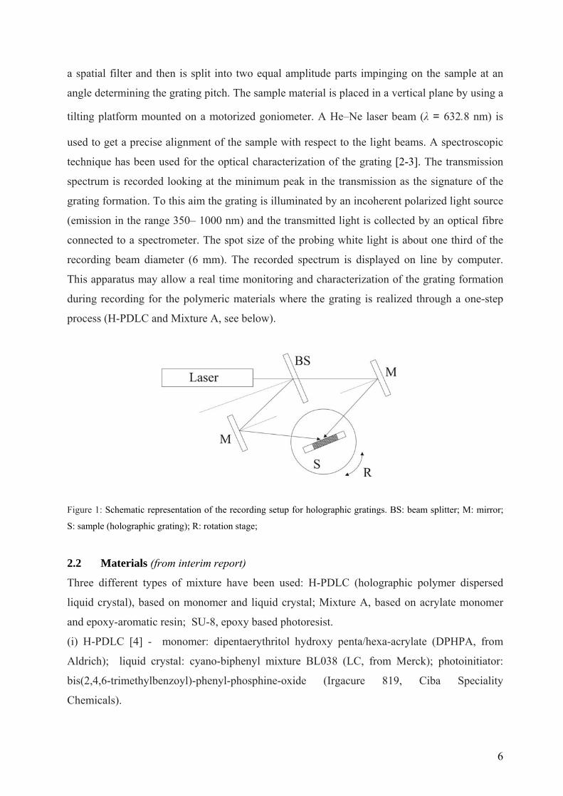
diffusion processes. The apparatus used for recording holographic gratings is the standard one
shown in figure 1 [1]. It basically consists of a laser source (a diode blue laser operating at 405
nm or a He-Cd operating at 325 nm), whose beam is spatially cleaned by a beam expander and
6
a spatial filter and then is split into two equal amplitude parts impinging on the sample at an
angle determining the grating pitch. The sample material is placed in a vertical plane by using a
tilting platform mounted on a motorized goniometer. A He–Ne laser beam (λ = 632.8 nm) is
used to get a precise alignment of the sample with respect to the light beams. A spectroscopic
technique has been used for the optical characterization of the grating [2-3]. The transmission
spectrum is recorded looking at the minimum peak in the transmission as the signature of the
grating formation. To this aim the grating is illuminated by an incoherent polarized light source
(emission in the range 350– 1000 nm) and the transmitted light is collected by an optical fibre
connected to a spectrometer. The spot size of the probing white light is about one third of the
recording beam diameter (6 mm). The recorded spectrum is displayed on line by computer.
This apparatus may allow a real time monitoring and characterization of the grating formation
during recording for the polymeric materials where the grating is realized through a one-step
process (H-PDLC and Mixture A, see below).
Figure 1: Schematic representation of the recording setup for holographic gratings. BS: beam splitter; M: mirror;
S: sample (holographic grating); R: rotation stage;
2.2 Materials (from interim report)
Three different types of mixture have been used: H-PDLC (holographic polymer dispersed
liquid crystal), based on monomer and liquid crystal; Mixture A, based on acrylate monomer
and epoxy-aromatic resin; SU-8, epoxy based photoresist.
(i) H-PDLC [4] - monomer: dipentaerythritol hydroxy penta/hexa-acrylate (DPHPA, from
Aldrich); liquid crystal: cyano-biphenyl mixture BL038 (LC, from Merck); photoinitiator:
bis(2,4,6-trimethylbenzoyl)-phenyl-phosphine-oxide (Irgacure 819, Ciba Speciality
Chemicals).

7
A typical mass ratio used between monomer (M), liquid crystal (LC) and photoinitiator (PI) is:
M:LC:PI= 55:32:13. Grating recording is realized by polymerization induced phase separation
with final morphology made by polymer rich regions alternated with liquid crystal rich regions.
(ii) Mixture A [5]: acrylate monomer :di-pentaerythritol-hydroxypenta/ hexa-acrylate, 69.5%
(DPHPA, from Aldrich); epoxy-aromatic resin: tri-phenyl-o-methane-tri-glycidil-ether, 29,5%
(TPMTGE, from Aldrich); photoinitiator: bis(2,4,6-trimethylbenzoyl)-phenyl-phosphine-oxide,
1% (Irgacure 819, Ciba Speciality Chemicals). Grating recording is realized by acrylate
polymerization with a final morphology made by acrylate polymer rich regions alternated with
resin rich regions. Figure 2 shows the reflection properties of a grating made with this mixture.
500 550 600 650 7004000
6000
8000
10000
12000
Inte
nsity
(arb
. uni
ts)
λ (nm)
Figure 2: Transmission spectrum of a grating realized by using Mixture A
(iii) SU-8 [6]: epoxy based photoresist. In this case the recording process follows two steps: to
record the grating, a solution containing a 14% by weight of SU-8 (Miller-Stephenson), a 1.4%
of photoinitiatior (a 50% solution of triarylsulfoniurn hexafluoroantirnonate in propylene
carbonate), and an 84.6% of solvent (cyclopentanone) is spin-coated at 3000 rpm on an ITO-
coated glass substrate. Afterwards the sample is heated at 90 °C to allow the solvent
evaporation and then exposed to the interference pattern generated by two He-Cd s-polarized
laser beams (I = 140 mW/cm2, exposure time t = 1.5 s, wavelength λw = 325 nm). The sample is
heated again to polymerize the irradiated parts and washed in 1-Methoxy-2-propyl acetate
(PMA) and isopropanol for few seconds to completely remove the unpolymerized parts. A
grating made by alternating stripes of SU-8 polymer and air is obtained as shown in fig. 3.
8
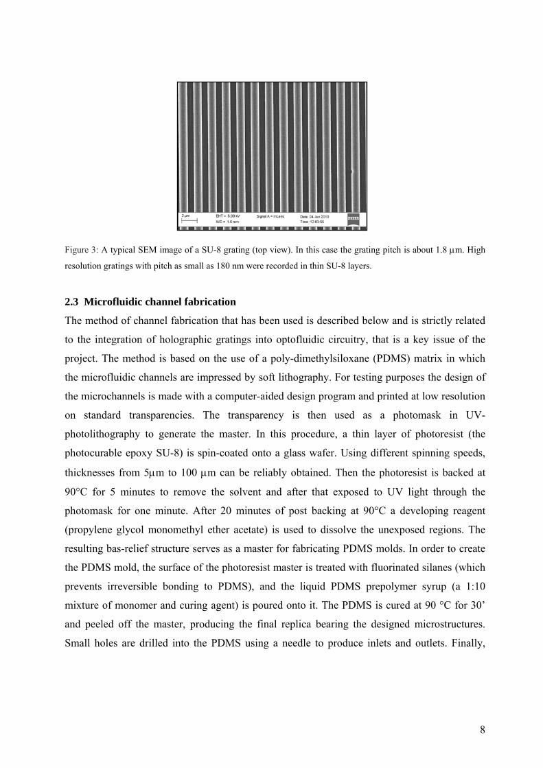
Figure 3: A typical SEM image of a SU-8 grating (top view). In this case the grating pitch is about 1.8 μm. High
resolution gratings with pitch as small as 180 nm were recorded in thin SU-8 layers.
2.3 Microfluidic channel fabrication
The method of channel fabrication that has been used is described below and is strictly related
to the integration of holographic gratings into optofluidic circuitry, that is a key issue of the
project. The method is based on the use of a poly-dimethylsiloxane (PDMS) matrix in which
the microfluidic channels are impressed by soft lithography. For testing purposes the design of
the microchannels is made with a computer-aided design program and printed at low resolution
on standard transparencies. The transparency is then used as a photomask in UV-
photolithography to generate the master. In this procedure, a thin layer of photoresist (the
photocurable epoxy SU-8) is spin-coated onto a glass wafer. Using different spinning speeds,
thicknesses from 5μm to 100 μm can be reliably obtained. Then the photoresist is backed at
90°C for 5 minutes to remove the solvent and after that exposed to UV light through the
photomask for one minute. After 20 minutes of post backing at 90°C a developing reagent
(propylene glycol monomethyl ether acetate) is used to dissolve the unexposed regions. The
resulting bas-relief structure serves as a master for fabricating PDMS molds. In order to create
the PDMS mold, the surface of the photoresist master is treated with fluorinated silanes (which
prevents irreversible bonding to PDMS), and the liquid PDMS prepolymer syrup (a 1:10
mixture of monomer and curing agent) is poured onto it. The PDMS is cured at 90 °C for 30’
and peeled off the master, producing the final replica bearing the designed microstructures.
Small holes are drilled into the PDMS using a needle to produce inlets and outlets. Finally,
9
PDMS can reversibly seal to itself or other flat surfaces by conformal contact (via Van der
Waals forces). Seals are watertight and can be formed under ambient conditions.
2.4 Design of DFB geometries
The integration of holographic gratings in microfluidics channels allows designing Distributed
Feedback (DFB) geometries for optofluidic lasers.
The basic configuration is made by the following elements:
a) microchannels in PDMS as described in section 2.3;
b) holographic grating recorded on a cover glass;
c) part a) and b) sealed together in order to have the grating structures on the
bottom of the microchannel.
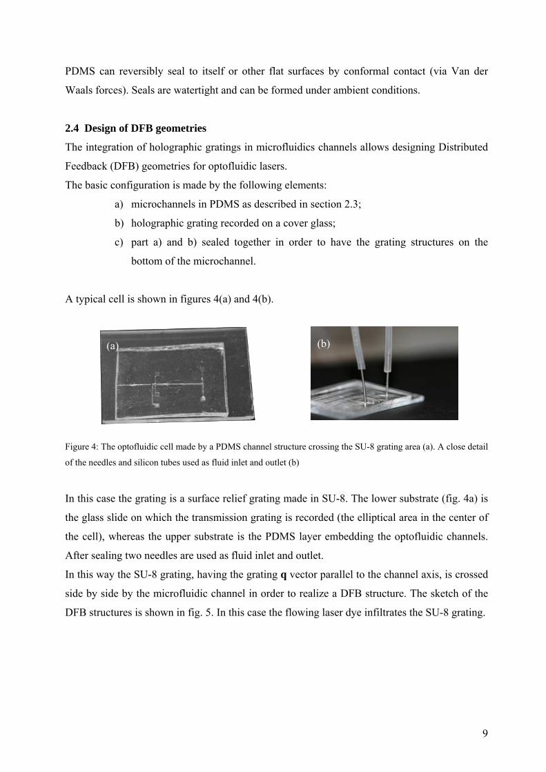
A typical cell is shown in figures 4(a) and 4(b).
Figure 4: The optofluidic cell made by a PDMS channel structure crossing the SU-8 grating area (a). A close detail
of the needles and silicon tubes used as fluid inlet and outlet (b)
In this case the grating is a surface relief grating made in SU-8. The lower substrate (fig. 4a) is
the glass slide on which the transmission grating is recorded (the elliptical area in the center of
the cell), whereas the upper substrate is the PDMS layer embedding the optofluidic channels.
After sealing two needles are used as fluid inlet and outlet.
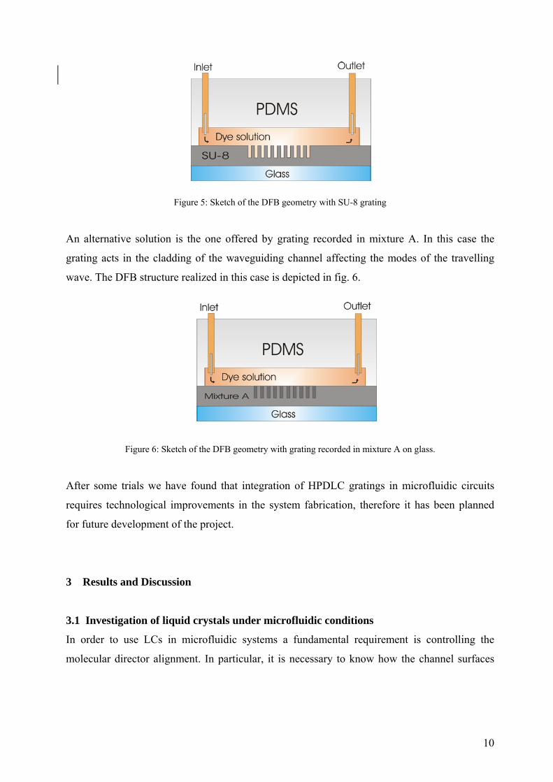
In this way the SU-8 grating, having the grating q vector parallel to the channel axis, is crossed
side by side by the microfluidic channel in order to realize a DFB structure. The sketch of the
DFB structures is shown in fig. 5. In this case the flowing laser dye infiltrates the SU-8 grating.
(a) (b)
10
Figure 5: Sketch of the DFB geometry with SU-8 grating
An alternative solution is the one offered by grating recorded in mixture A. In this case the
grating acts in the cladding of the waveguiding channel affecting the modes of the travelling
wave. The DFB structure realized in this case is depicted in fig. 6.
Figure 6: Sketch of the DFB geometry with grating recorded in mixture A on glass.
After some trials we have found that integration of HPDLC gratings in microfluidic circuits
requires technological improvements in the system fabrication, therefore it has been planned
for future development of the project.
3 Results and Discussion
3.1 Investigation of liquid crystals under microfluidic conditions
In order to use LCs in microfluidic systems a fundamental requirement is controlling the
molecular director alignment. In particular, it is necessary to know how the channel surfaces
11
and the flow parameters affect the LC orientation. A series of experiments have been carried
out for this purpose.
In standard LC devices, alignment is controlled via deposition of thin aligning layers on the cell
boundaries. In our case, we first checked the natural alignment of LC (we used the E7 nematic
mixture) on PDMS and found that LC director spontaneously aligns itself normally to the
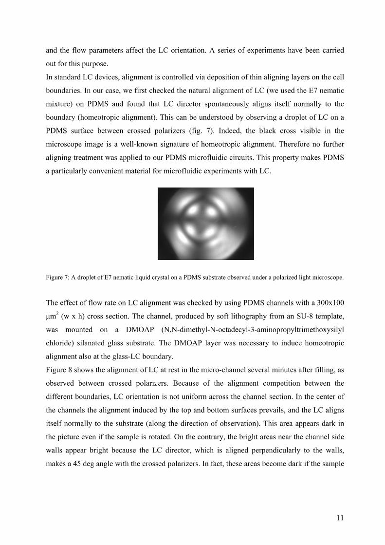
boundary (homeotropic alignment). This can be understood by observing a droplet of LC on a
PDMS surface between crossed polarizers (fig. 7). Indeed, the black cross visible in the
microscope image is a well-known signature of homeotropic alignment. Therefore no further
aligning treatment was applied to our PDMS microfluidic circuits. This property makes PDMS
a particularly convenient material for microfluidic experiments with LC.
Figure 7: A droplet of E7 nematic liquid crystal on a PDMS substrate observed under a polarized light microscope.
The effect of flow rate on LC alignment was checked by using PDMS channels with a 300x100
μm2 (w x h) cross section. The channel, produced by soft lithography from an SU-8 template,
was mounted on a DMOAP (N,N-dimethyl-N-octadecyl-3-aminopropyltrimethoxysilyl
chloride) silanated glass substrate. The DMOAP layer was necessary to induce homeotropic
alignment also at the glass-LC boundary.
Figure 8 shows the alignment of LC at rest in the micro-channel several minutes after filling, as
observed between crossed polarizers. Because of the alignment competition between the
different boundaries, LC orientation is not uniform across the channel section. In the center of
the channels the alignment induced by the top and bottom surfaces prevails, and the LC aligns
itself normally to the substrate (along the direction of observation). This area appears dark in
the picture even if the sample is rotated. On the contrary, the bright areas near the channel side
walls appear bright because the LC director, which is aligned perpendicularly to the walls,
makes a 45 deg angle with the crossed polarizers. In fact, these areas become dark if the sample
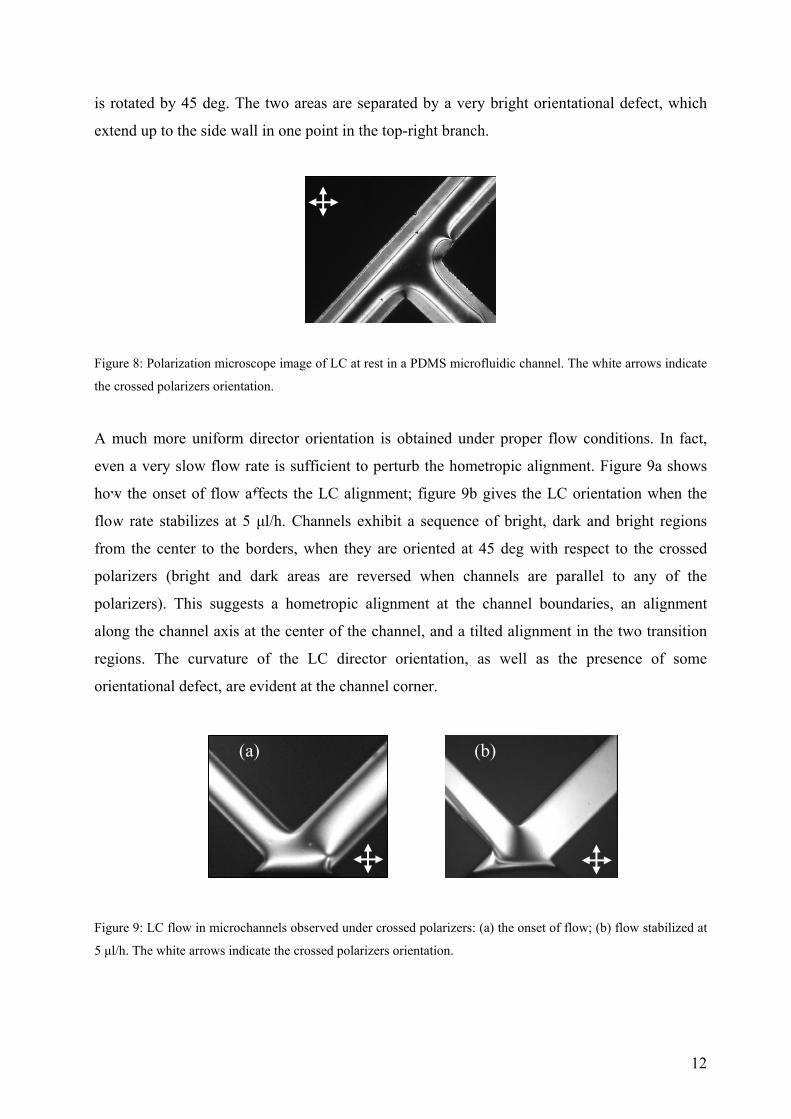
12
is rotated by 45 deg. The two areas are separated by a very bright orientational defect, which
extend up to the side wall in one point in the top-right branch.
Figure 8: Polarization microscope image of LC at rest in a PDMS microfluidic channel. The white arrows indicate
the crossed polarizers orientation.
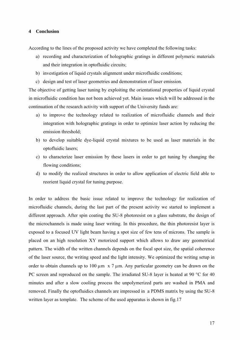
A much more uniform director orientation is obtained under proper flow conditions. In fact,
even a very slow flow rate is sufficient to perturb the hometropic alignment. Figure 9a shows
how the onset of flow affects the LC alignment; figure 9b gives the LC orientation when the
flow rate stabilizes at 5 μl/h. Channels exhibit a sequence of bright, dark and bright regions
from the center to the borders, when they are oriented at 45 deg with respect to the crossed
polarizers (bright and dark areas are reversed when channels are parallel to any of the
polarizers). This suggests a hometropic alignment at the channel boundaries, an alignment
along the channel axis at the center of the channel, and a tilted alignment in the two transition
regions. The curvature of the LC director orientation, as well as the presence of some
orientational defect, are evident at the channel corner.
Figure 9: LC flow in microchannels observed under crossed polarizers: (a) the onset of flow; (b) flow stabilized at
5 μl/h. The white arrows indicate the crossed polarizers orientation.
(b) (a)

13
Interestingly, when the flow stabilizes the central bright region broadens and almost reaches
the channel boundaries, where two thin dark layers are just visible. In fact, flow induces a
viscous torque on LC director and thus a very homogeneous LC alignment along the flow
direction is obtained in the whole channel.
Finally, at higher flow rates (over 15÷20 μl/h) an increasing number of disclination defects
appears along the whole channel length.
As both ordinary and extraordinary E7 refractive indices (no = 1.52, ne = 1.75) are larger than
PDMS refractive index (n = 1.41), the LC microchannel can be used as an optofluidic
waveguide. This was demonstrated by coupling the light from a He-Ne laser (λ = 633 nm) into
the microfluidic channel via a multimode optical fiber. The set-up in fig. 10 shows light
propagation over a distance >1 cm.
Figure 10: Image of a LC optofluidic waveguide.
3.2 Optofluidic microlasers
a) Preliminary test of DFB geometry realized with grating recorded in Mixture A (non
optofluidic) (from interim report)
A first attempt has been performed by using the configuration sketched in the inset of fig.11 In
this device the grating is recorded between the ends of two multi-mode optical fibers
(core/cladding diameter 105/125 μm; NA=0.22), aligned in the direction parallel to the grating
vector q. In order to obtain laser emission we doped the original Mixture A with Rhodamine
6G, a photo-luminescent dye, at a final concentration of 10-2 M. Lasing action is achieved by
optically pumping the structure by means of the second harmonic (λ = 532 nm) of a 4 ns pulsed
Nd:YAG laser. The pump beam is focused by a cylindrical lens just in the area of the grating
connecting the two optical fibers (see the inset of fig. 11).

14
The laser emission is collected by the two fibers and analyzed by a spectrometer. A typical
emission spectrum is reported in fig. 11. A laser peak with a FWHM bandwidth < 2 nm appears
on the side of the grating reflection band, as expected for a DFB configuration. The emission
peak is superimposed to the Rhodamine 6G emission band, whose maximum depends on the
dye concentration. By collecting data corresponding to different pumping energy densities,
namely from 230 μJ/cm2 to ~12 mJ/cm2, a lasing threshold of 2 mJ/cm2 has been determined.
Figure 11: Spectrum of the radiation emitted by the bidirectional microlaser based on holographic grating
recorded in Mixture A at pumping energy density of ~12 mJ/cm2. The narrow peak (FWHM< 2nm) of the laser
emission is superimposed to the broad dye emission band. The inset shows a sketch of the bi-directional lasing
action.
b) Test of DFB geometry designed for microfluidic conditions
A second scheme is shown in fig. 12. It is already designed for microfluidic integration even if
the channels realization must be improved to get a reliable operation under flowing condition.
In order to obtain this configuration a 100 μm thick Mylar stripe is placed between two glass
slides and the cell is filled by capillarity with Mixture A. First the grating is recorded, then the
whole structure is polymerized under a UV lamp. After polymerization the Mylar stripe is
removed and the microfluidic channel is created. The channel is filled with a solution of
Rhodamine 6G in ethanol and pumped by a frequency-doubled pulsed Nd:YAG laser working
at 532 nm. Lasing was detected through an optical fiber connected to a spectrometer. A
preliminary experimental result is reported in fig. 13 where the light power emitted by the
device is plotted vs the pump pulse energy.
600 700
800
1600
2400In
tens
ity (a
rb. u
nits
)
λ (nm)

15
Figure 12: A sketch of a tested microfluidic laser. The green arrow represents the pump pulsed light source. Lasing
is detected through an optical fiber connected to a high resolution real time spectrometer.
-1 0 1 2 3 4 5 6 7
0
1000
2000
3000
4000
Ligh
t int
ensi
ty (a
rb. u
nits
)
pumping energy (mJ)
Figure 13: Signal due to laser emission vs pulse energy for the device depicted in fig.12.
c) DFB laser based on integration of holographic gratings in microfluidic circuits
The activity has been focused on investigation of laser action using DFB geometries described
in section 2.4 (fig. 5 and fig.6). A sketch of the optofluidic laser is shown in fig. 14. A 10-4 M
solution of Rodhamine 6G in ethanol has been used. Like in the previous cases pumping is
provided by second harmonic of a Nd-YAG pulsed laser (5 ns) focused by a cylindrical lens on
the microfluidic channel. A picture of the device under pumping is shown in fig.15.
Figure 14: Sketch of the investigated optofluidic laser. The green arrow represents the pump pulsed light source.
Lasing is detected through an optical fiber connected to a high resolution real time spectrometer.

16
Figure 15: Picture of the operating optofluidic laser
The lasing action is evident in fig.16 where it is reported the signal recorded by the
spectrophotometer vs wavelength. The laser spike at ~ 570 nm over the broad emission
spectrum of Rhodamine 6G is clear . The signal due to the pumping beam at 532 nm is also
evident on the left side of the luminescence spectrum. At flow rate of 15 μl/min emission was
recorded at a pumping rate of 20 Hz, even if prolonged operation at this rate resulted in damage
of the gratings with consequent stop of the lasing action. Optimization of the system in order to
reduce the pumping energy is required in order the realize a long term working device. The
threshold for laser emission of the present device has been measured to be ~ 0.5 mJ
Figure 16: Spectrum recorded by spectrophotometer during the operation of the optofluidic laser
17
4 Conclusion
According to the lines of the proposed activity we have completed the following tasks:
a) recording and characterization of holographic gratings in different polymeric materials
and their integration in optofluidic circuits;
b) investigation of liquid crystals alignment under microfluidic conditions;
c) design and test of laser geometries and demonstration of laser emission.
The objective of getting laser tuning by exploiting the orientational properties of liquid crystal
in microfluidic condition has not been achieved yet. Main issues which will be addressed in the
continuation of the research activity with support of the University funds are:
a) to improve the technology related to realization of microfluidic channels and their
integration with holographic gratings in order to optimize laser action by reducing the
emission threshold;
b) to develop suitable dye-liquid crystal mixtures to be used as laser materials in the
optofluidic lasers;
c) to characterize laser emission by these lasers in order to get tuning by changing the
flowing conditions;
d) to modify the realized structures in order to allow application of electric field able to
reorient liquid crystal for tuning purpose.
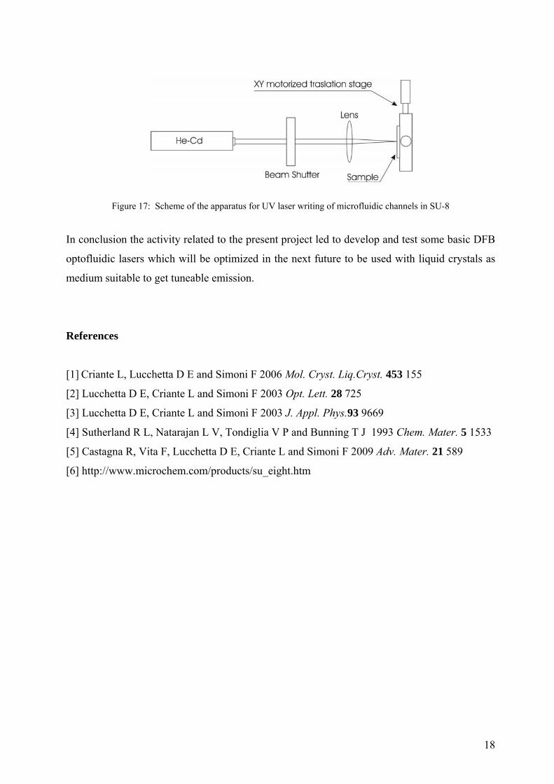
In order to address the basic issue related to improve the technology for realization of
microfluidic channels, during the last part of the present activity we started to implement a
different approach. After spin coating the SU-8 photoresist on a glass substrate, the design of
the microchannels is made using laser writing. In this procedure, the thin photoresist layer is
exposed to a focused UV light beam having a spot size of few tens of microns. The sample is
placed on an high resolution XY motorized support which allows to draw any geometrical
pattern. The width of the written channels depends on the focal spot size, the spatial coherence
of the laser source, the writing speed and the light intensity. We optimized the writing setup in
order to obtain channels up to 100 μm x 7 μm. Any particular geometry can be drawn on the
PC screen and reproduced on the sample. The irradiated SU-8 layer is heated at 90 °C for 40
minutes and after a slow cooling process the unpolymerized parts are washed in PMA and
removed. Finally the optofluidics channels are impressed in a PDMS matrix by using the SU-8
written layer as template. The scheme of the used apparatus is shown in fig.17
18
Figure 17: Scheme of the apparatus for UV laser writing of microfluidic channels in SU-8
In conclusion the activity related to the present project led to develop and test some basic DFB
optofluidic lasers which will be optimized in the next future to be used with liquid crystals as
medium suitable to get tuneable emission.
References
[1] Criante L, Lucchetta D E and Simoni F 2006 Mol. Cryst. Liq.Cryst. 453 155
[2] Lucchetta D E, Criante L and Simoni F 2003 Opt. Lett. 28 725
[3] Lucchetta D E, Criante L and Simoni F 2003 J. Appl. Phys.93 9669
[4] Sutherland R L, Natarajan L V, Tondiglia V P and Bunning T J 1993 Chem. Mater. 5 1533
[5] Castagna R, Vita F, Lucchetta D E, Criante L and Simoni F 2009 Adv. Mater. 21 589
[6] http://www.microchem.com/products/su_eight.htm
19
List of Symbols, Abbreviations, and Acronyms
DFB – Distibuted FeedBack
H-PDLC – Holographic Polymer Dispersed Liquid Crystals
LC – Liquid Crystal
SU-8 – Epoxy based negative resists
DPHPA – dipentaerythritol hydroxy penta/hexa-acrylate
BL038 – cyano-biphenyl liquid crystal mixture
Irgacure 819 – bis(2,4,6-trimethylbenzoyl)- phenyl-phosphine-oxide
TPMTGE – epoxy-aromatic resin: tri-phenyl-o-methane-tri-glycidil-ether
PDMS – poly-dimethylsiloxane
PMA – 1-Methoxy-2-propyl acetate
Prof. Francesco Simoni
(Principal Investigator)