tuners, operating experience and performance...
TRANSCRIPT

FREQUENCY TUNERS, OPERATING EXPERIENCE AND PERFORMANCE RECOVERY
Yoshiyuki Morita#, KEK, Oho 1-1, Tsukuba, Ibaraki, Japan
Abstract
Several important issues for the SRF cavity system will be discussed. One issue is a tuner system. Recent tuner systems have significantly advanced at many laboratories and a number of tuner technologies now exist for a variety of requirements. We will review those tuner systems and discuss applicability.
The second issue is stability of cavity operation. The SRF systems for the Higgs factory must have as low trip rate as possible. Maintenance work is necessary to keep the trip rate at low level. The SRF cavity design that takes into account the ease of maintenance is required. Operational experience of KEKB is an useful example for practical considerations.
The third issue is performance degradation and its recovery method. In a long-term operation, cavity performance gradually degrades. A recovery method with a low risk, low cost and in a short period of time is desirable. We have developed a horizontal high pressure rinsing that can be applied directly to the cavity in a cryomodule. Our degraded cavities successfully recovered using this method.
In this paper, we will report the tuner systems for SRF cavities for appropriate design choice, the operating experience and cavity performance recovery.
INTRODUCTION There are several important issues for designing SRF
cavities and cryomodules. In this report three main issues will be discussed. Those are frequency tuners, operating experience and performance recovery.
Frequency tuner is an important system for the cavity. Its functions are to tune the cavity to its resonant frequency, detune to compensate the beam loading, and help to stabilize its RF amplitude and phase. At an early stage of the SRF cavity development, many types of tuners were tried and applied. Now frequency tuners have advanced for a variety of requirements. One can select an
review tuner designs developed at many laboratories. Operating experience gained elsewhere provides very
useful information for designing suitable system for the machine operation. Since the Higgs factory requires high integrated luminosity, RF trip rates and down time of the SRF cavities should be as low as possible. In order to keep the low trip rate, maintenance works are essential. Cavity performance degradation in a long term operation also gives a useful information. As an example, cavity RF trip rates, maintenance work, troubles of the cavity
operation and performance degradation of the SRF cavities at KEKB are presented.
Performance recovery is needed or desired for a long-term operation. A recovery method should be low risk, low cost and in short period of time. KEK recently developed a horizontal high pressure rinsing method that can be directly applied to a cavity in a cryomodule. Two degraded KEKB cavity modules successfully recovered after the horizontal high pressure rinsing. The R&D effort, details of horizontal high pressure rinsing and application to cryomodules are presented.
FREQUENCY TUNERS
Tuners at An Early Stage
Four frequency tuner systems at an early stage of development are reviewed [1]. The TRISTAN tuner at KEK had a lever system. The lever was driven by a screw jack with a stepping motor. The jack has a piezoactuator for fine tuning. The CESRIII tuner at Cornell University had a flex hinge system with no backlash driven by a stepping motor. The CEBAF tuner system at JLab had a gear shaft system driven by a stepping motor and harmonic gear combination exterior to the cryomodule. The LEPII tuner system at CERN utilized thermal expansion and contraction of three Ni bars. He gas cools the bars for contraction while coil heater warm up the bars for expansion. Exciting coils surrounded those bars to produce magnetostrictive effect for fine tuning. There were a variety of mechanism of the main tuners. The fine sub-tuner was a piezoactuator or a magneto-strictive tuner. Table 1 summarises tuner parameters.
Table 1: Tuner Parameters
CEBAF TRISTAN
CESR III LEP II
Frequency (MHz)
1500 508 500 325
Mechanism Drive shaft
Lever arm
Flex hinge Ni bars
Driver Stepping motor
Stepping motor
Stepping motor
He cooling
and coil
heating
Sub-tuner Piezo 4kHz
Magneto-strictive ±1kHz
Sensitivity (kHz/mm)
500 80 320 40
Frequency
range (kHz)
400 800
(10 mm)
600 50 (10Hz/s)
Precision (Hz)
2 20 10 -
___________________________________________
SAT3B3 Proceedings of HF2014, Beijing, China
ISBN 978-3-95450-172-4200Co
pyrig
ht©
2015
CC-B
Y-3.
0an
dby
ther
espe
ctiv
eaut
hors
Superconducting RF
TRISTAN Tuner Development We present development of tuner systems for the
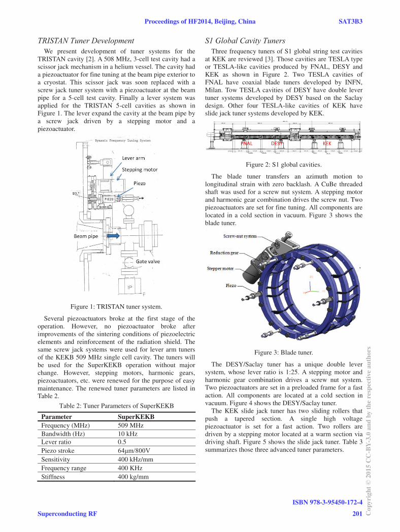
TRISTAN cavity [2]. A 508 MHz, 3-cell test cavity had a scissor jack mechanism in a helium vessel. The cavity had a piezoactuator for fine tuning at the beam pipe exterior to a cryostat. This scissor jack was soon replaced with a screw jack tuner system with a piezoactuator at the beam pipe for a 5-cell test cavity. Finally a lever system was applied for the TRISTAN 5-cell cavities as shown in Figure 1. The lever expand the cavity at the beam pipe by a screw jack driven by a stepping motor and a piezoactuator.
Figure 1: TRISTAN tuner system.
Several piezoactuators broke at the first stage of the operation. However, no piezoactuator broke after improvements of the sintering conditions of piezoelectric elements and reinforcement of the radiation shield. The same screw jack systems were used for lever arm tuners of the KEKB 509 MHz single cell cavity. The tuners will be used for the SuperKEKB operation without major change. However, stepping motors, harmonic gears, piezoactuators, etc. were renewed for the purpose of easy maintenance. The renewed tuner parameters are listed in Table 2.
Table 2: Tuner Parameters of SuperKEKB
Parameter SuperKEKB Frequency (MHz) 509 MHz Bandwidth (Hz) 10 kHz Lever ratio 0.5 Piezo stroke Sensitivity 400 kHz/mm Frequency range 400 KHz Stiffness 400 kg/mm
S1 Global Cavity Tuners Three frequency tuners of S1 global string test cavities
at KEK are reviewed [3]. Those cavities are TESLA type or TESLA-like cavities produced by FNAL, DESY and KEK as shown in Figure 2. Two TESLA cavities of FNAL have coaxial blade tuners developed by INFN, Milan. Tow TESLA cavities of DESY have double lever tuner systems developed by DESY based on the Saclay design. Other four TESLA-like cavities of KEK have slide jack tuner systems developed by KEK.
Figure 2: S1 global cavities.
The blade tuner transfers an azimuth motion to longitudinal strain with zero backlash. A CuBe threaded shaft was used for a screw nut system. A stepping motor and harmonic gear combination drives the screw nut. Two piezoactuators are set for fine tuning. All components are located in a cold section in vacuum. Figure 3 shows the blade tuner.
Figure 3: Blade tuner.
The DESY/Saclay tuner has a unique double lever system, whose lever ratio is 1:25. A stepping motor and harmonic gear combination drives a screw nut system. Two piezoactuators are set in a preloaded frame for a fast action. All components are located at a cold section in vacuum. Figure 4 shows the DESY/Saclay tuner.
The KEK slide jack tuner has two sliding rollers that push a tapered section. A single high voltage piezoactuator is set for a fast action. Two rollers are driven by a stepping motor located at a warm section via driving shaft. Figure 5 shows the slide jack tuner. Table 3 summarizes those three advanced tuner parameters.
Proceedings of HF2014, Beijing, China SAT3B3
Superconducting RFISBN 978-3-95450-172-4
201 Copy
right
©20
15CC
-BY-
3.0
and
byth
eres
pect
ivea
utho
rs
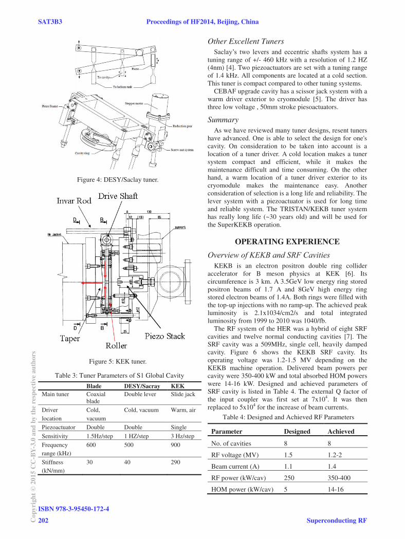
Figure 4: DESY/Saclay tuner.
Figure 5: KEK tuner.
Table 3: Tuner Parameters of S1 Global Cavity
Blade DESY/Sacray KEK Main tuner Coaxial
blade Double lever Slide jack
Driver location
Cold, vacuum
Cold, vacuum Warm, air
Piezoactuator Double Double Single
Sensitivity 1.5Hz/step 1 HZ/step 3 Hz/step
Frequency range (kHz)
600 500 900
Stiffness (kN/mm)
30 40 290
Other Excellent Tuners
tuning range of +/- 460 kHz with a resolution of 1.2 HZ (4nm) [4]. Two piezoactuators are set with a tuning range of 1.4 kHz. All components are located at a cold section. This tuner is compact compared to other tuning systems.
CEBAF upgrade cavity has a scissor jack system with a warm driver exterior to cryomodule [5]. The driver has three low voltage , 50mm stroke piesoactuators.
Summary
As we have reviewed many tuner designs, resent tuners have advanced. One is able to select the design for one's cavity. On consideration to be taken into account is a location of a tuner driver. A cold location makes a tuner system compact and efficient, while it makes the maintenance difficult and time consuming. On the other hand, a warm location of a tuner driver exterior to its cryomodule makes the maintenance easy. Another consideration of selection is a long life and reliability. The lever system with a piezoactuator is used for long time and reliable system. The TRISTAN/KEKB tuner system has really long life (~30 years old) and will be used for the SuperKEKB operation.
OPERATING EXPERIENCE
Overview of KEKB and SRF Cavities KEKB is an electron positron double ring collider
accelerator for B meson physics at KEK [6]. Its circumference is 3 km. A 3.5GeV low energy ring stored positron beams of 1.7 A and 8GeV high energy ring stored electron beams of 1.4A. Both rings were filled with the top-up injections with no ramp-up. The achieved peak luminosity is 2.1x1034/cm2/s and total integrated luminosity from 1999 to 2010 was 1040/fb.
The RF system of the HER was a hybrid of eight SRF cavities and twelve normal conducting cavities [7]. The SRF cavity was a 509MHz, single cell, heavily damped cavity. Figure 6 shows the KEKB SRF cavity. Its operating voltage was 1.2-1.5 MV depending on the KEKB machine operation. Delivered beam powers per cavity were 350-400 kW and total absorbed HOM powers were 14-16 kW. Designed and achieved parameters of SRF cavity is listed in Table 4. The external Q factor of the input coupler was first set at 7x10⁴. It was then replaced to 5x10⁴ for the increase of beam currents.
Table 4: Designed and Achieved RF Parameters
Parameter Designed Achieved
No. of cavities 8 8
RF voltage (MV) 1.5 1.2-2
Beam current (A) 1.1 1.4
RF power (kW/cav) 250 350-400
HOM power (kW/cav) 5 14-16
SAT3B3 Proceedings of HF2014, Beijing, China
ISBN 978-3-95450-172-4202Co
pyrig
ht©
2015
CC-B
Y-3.
0an
dby
ther
espe
ctiv
eaut
hors
Superconducting RF
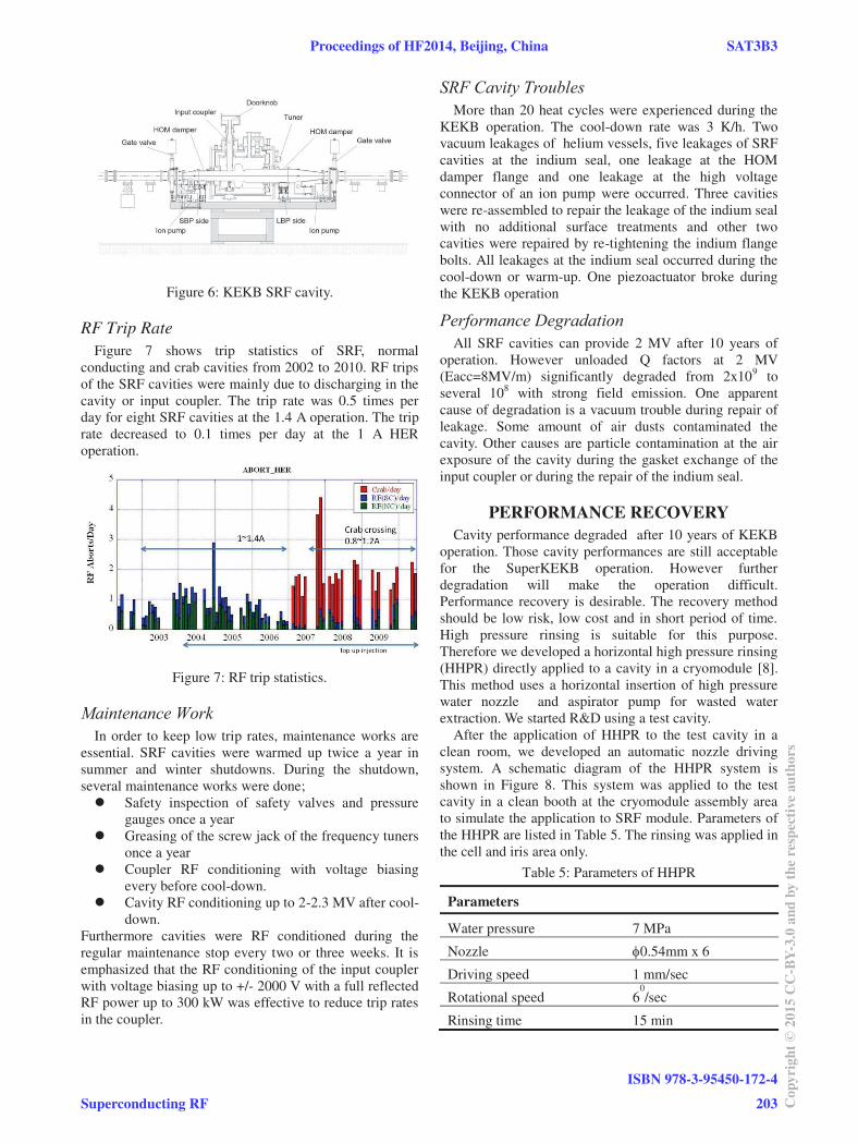
Figure 6: KEKB SRF cavity.
RF Trip Rate
Figure 7 shows trip statistics of SRF, normal conducting and crab cavities from 2002 to 2010. RF trips of the SRF cavities were mainly due to discharging in the cavity or input coupler. The trip rate was 0.5 times per day for eight SRF cavities at the 1.4 A operation. The trip rate decreased to 0.1 times per day at the 1 A HER operation.
Figure 7: RF trip statistics.
Maintenance Work In order to keep low trip rates, maintenance works are
essential. SRF cavities were warmed up twice a year in summer and winter shutdowns. During the shutdown, several maintenance works were done;
Safety inspection of safety valves and pressure gauges once a year
Greasing of the screw jack of the frequency tuners once a year
Coupler RF conditioning with voltage biasing every before cool-down.
Cavity RF conditioning up to 2-2.3 MV after cool-down.
Furthermore cavities were RF conditioned during the regular maintenance stop every two or three weeks. It is emphasized that the RF conditioning of the input coupler with voltage biasing up to +/- 2000 V with a full reflected RF power up to 300 kW was effective to reduce trip rates in the coupler.
SRF Cavity Troubles More than 20 heat cycles were experienced during the
KEKB operation. The cool-down rate was 3 K/h. Two vacuum leakages of helium vessels, five leakages of SRF cavities at the indium seal, one leakage at the HOM damper flange and one leakage at the high voltage connector of an ion pump were occurred. Three cavities were re-assembled to repair the leakage of the indium seal with no additional surface treatments and other two cavities were repaired by re-tightening the indium flange bolts. All leakages at the indium seal occurred during the cool-down or warm-up. One piezoactuator broke during the KEKB operation
Performance Degradation All SRF cavities can provide 2 MV after 10 years of
operation. However unloaded Q factors at 2 MV (Eacc=8MV/m) significantly degraded from 2x10⁹ to several 108 with strong field emission. One apparent cause of degradation is a vacuum trouble during repair of leakage. Some amount of air dusts contaminated the cavity. Other causes are particle contamination at the air exposure of the cavity during the gasket exchange of the input coupler or during the repair of the indium seal.
PERFORMANCE RECOVERY Cavity performance degraded after 10 years of KEKB
operation. Those cavity performances are still acceptable for the SuperKEKB operation. However further degradation will make the operation difficult. Performance recovery is desirable. The recovery method should be low risk, low cost and in short period of time. High pressure rinsing is suitable for this purpose. Therefore we developed a horizontal high pressure rinsing (HHPR) directly applied to a cavity in a cryomodule [8]. This method uses a horizontal insertion of high pressure water nozzle and aspirator pump for wasted water extraction. We started R&D using a test cavity.
After the application of HHPR to the test cavity in a clean room, we developed an automatic nozzle driving system. A schematic diagram of the HHPR system is shown in Figure 8. This system was applied to the test cavity in a clean booth at the cryomodule assembly area to simulate the application to SRF module. Parameters of the HHPR are listed in Table 5. The rinsing was applied in the cell and iris area only.
Table 5: Parameters of HHPR
Parameters
Water pressure 7 MPa
Nozzle 0.54mm x 6
Driving speed 1 mm/sec
Rotational speed 60/sec
Rinsing time 15 min
Proceedings of HF2014, Beijing, China SAT3B3
Superconducting RFISBN 978-3-95450-172-4
203 Copy
right
©20
15CC
-BY-
3.0
and
byth
eres
pect
ivea
utho
rs
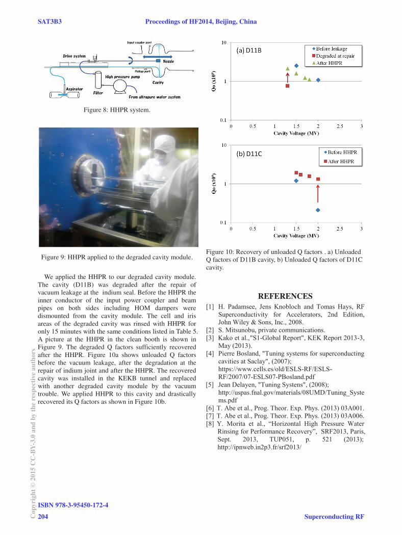
Figure 8: HHPR system.
Figure 9: HHPR applied to the degraded cavity module.
We applied the HHPR to our degraded cavity module.
The cavity (D11B) was degraded after the repair of vacuum leakage at the indium seal. Before the HHPR the inner conductor of the input power coupler and beam pipes on both sides including HOM dampers were dismounted from the cavity module. The cell and iris areas of the degraded cavity was rinsed with HHPR for only 15 minutes with the same conditions listed in Table 5. A picture at the HHPR in the clean booth is shown in Figure 9. The degraded Q factors sufficiently recovered after the HHPR. Figure 10a shows unloaded Q factors before the vacuum leakage, after the degradation at the repair of indium joint and after the HHPR. The recovered cavity was installed in the KEKB tunnel and replaced with another degraded cavity module by the vacuum trouble. We applied HHPR to this cavity and drastically recovered its Q factors as shown in Figure 10b.
Figure 10: Recovery of unloaded Q factors . a) Unloaded Q factors of D11B cavity, b) Unloaded Q factors of D11C cavity.
REFERENCES
SAT3B3 Proceedings of HF2014, Beijing, China
ISBN 978-3-95450-172-4204Co
pyrig
ht©
2015
CC-B
Y-3.
0an
dby
ther
espe
ctiv
eaut
hors
Superconducting RF