tuning the pietta cap & ball for · pdf filetuning the pietta cap & ball for...
TRANSCRIPT
1
Tuning the Pietta Cap & Ball for Competition Part 2. Fixing the Problem Areas
By Larsen E. Pettifogger
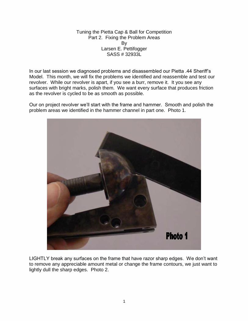
SASS # 32933L In our last session we diagnosed problems and disassembled our Pietta .44 Sheriff’s Model. This month, we will fix the problems we identified and reassemble and test our revolver. While our revolver is apart, if you see a burr, remove it. It you see any surfaces with bright marks, polish them. We want every surface that produces friction as the revolver is cycled to be as smooth as possible. Our on project revolver we’ll start with the frame and hammer. Smooth and polish the problem areas we identified in the hammer channel in part one. Photo 1.
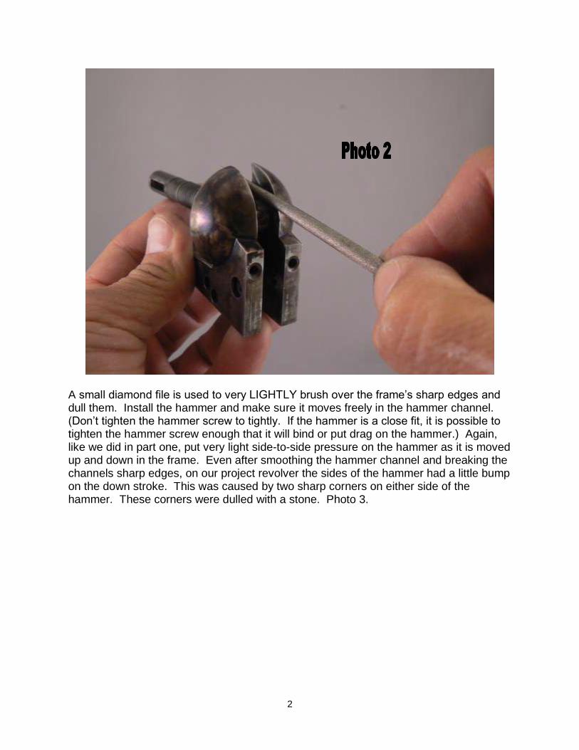
LIGHTLY break any surfaces on the frame that have razor sharp edges. We don’t want to remove any appreciable amount metal or change the frame contours, we just want to lightly dull the sharp edges. Photo 2.
2
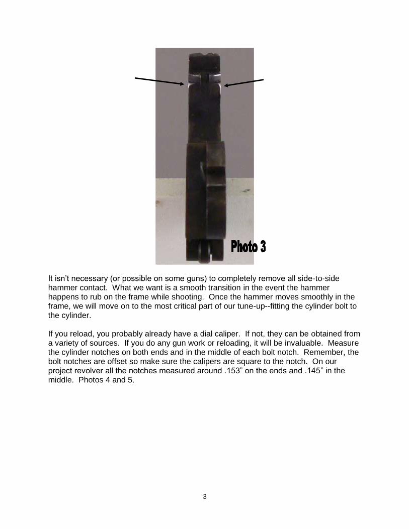
A small diamond file is used to very LIGHTLY brush over the frame’s sharp edges and dull them. Install the hammer and make sure it moves freely in the hammer channel. (Don’t tighten the hammer screw to tightly. If the hammer is a close fit, it is possible to tighten the hammer screw enough that it will bind or put drag on the hammer.) Again, like we did in part one, put very light side-to-side pressure on the hammer as it is moved up and down in the frame. Even after smoothing the hammer channel and breaking the channels sharp edges, on our project revolver the sides of the hammer had a little bump on the down stroke. This was caused by two sharp corners on either side of the hammer. These corners were dulled with a stone. Photo 3.
3
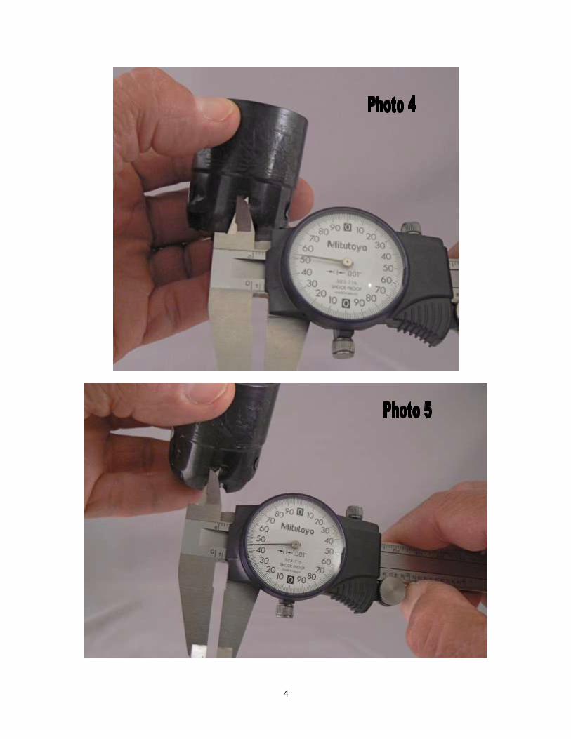
It isn’t necessary (or possible on some guns) to completely remove all side-to-side hammer contact. What we want is a smooth transition in the event the hammer happens to rub on the frame while shooting. Once the hammer moves smoothly in the frame, we will move on to the most critical part of our tune-up--fitting the cylinder bolt to the cylinder. If you reload, you probably already have a dial caliper. If not, they can be obtained from a variety of sources. If you do any gun work or reloading, it will be invaluable. Measure the cylinder notches on both ends and in the middle of each bolt notch. Remember, the bolt notches are offset so make sure the calipers are square to the notch. On our project revolver all the notches measured around .153” on the ends and .145” in the middle. Photos 4 and 5.
4
5
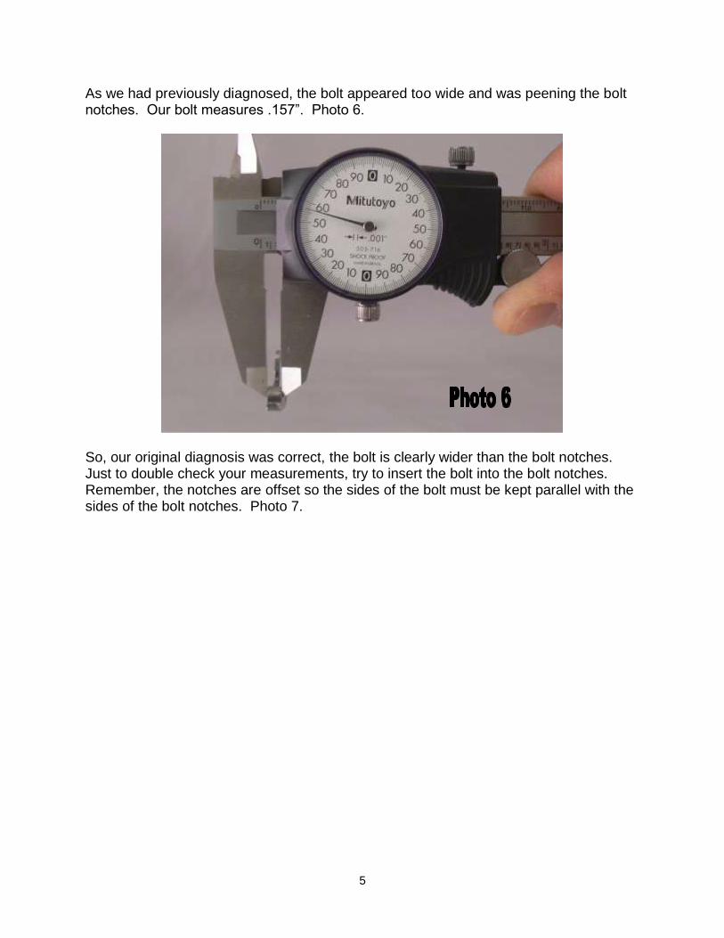
As we had previously diagnosed, the bolt appeared too wide and was peening the bolt notches. Our bolt measures .157”. Photo 6.
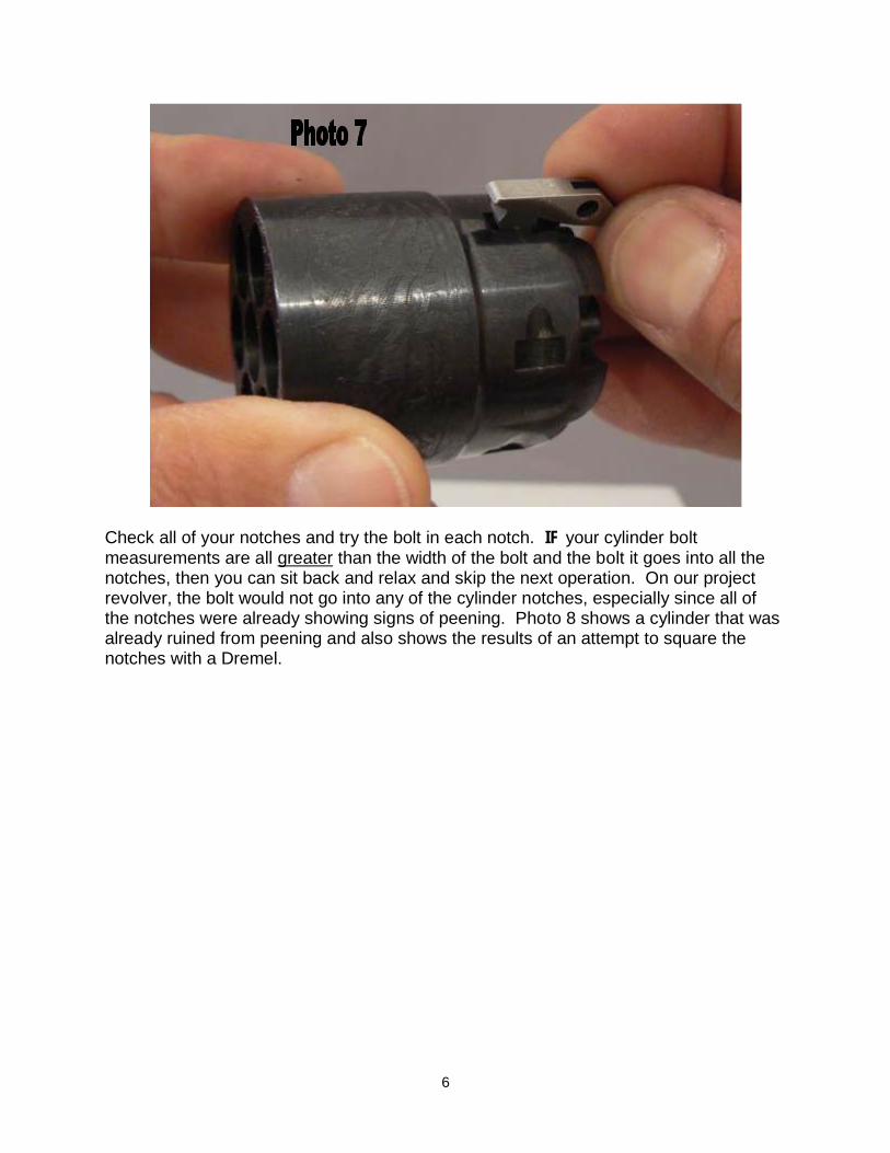
So, our original diagnosis was correct, the bolt is clearly wider than the bolt notches. Just to double check your measurements, try to insert the bolt into the bolt notches. Remember, the notches are offset so the sides of the bolt must be kept parallel with the sides of the bolt notches. Photo 7.
6
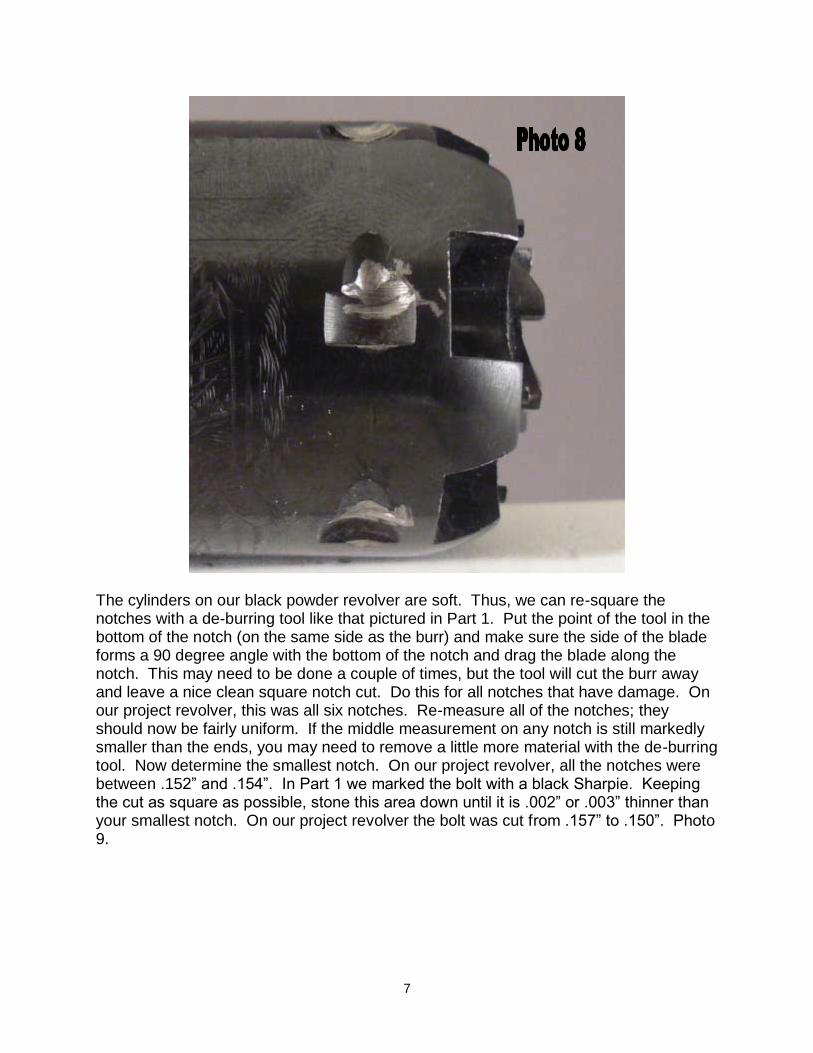
Check all of your notches and try the bolt in each notch. IF your cylinder bolt measurements are all greater than the width of the bolt and the bolt it goes into all the notches, then you can sit back and relax and skip the next operation. On our project revolver, the bolt would not go into any of the cylinder notches, especially since all of the notches were already showing signs of peening. Photo 8 shows a cylinder that was already ruined from peening and also shows the results of an attempt to square the notches with a Dremel.
7
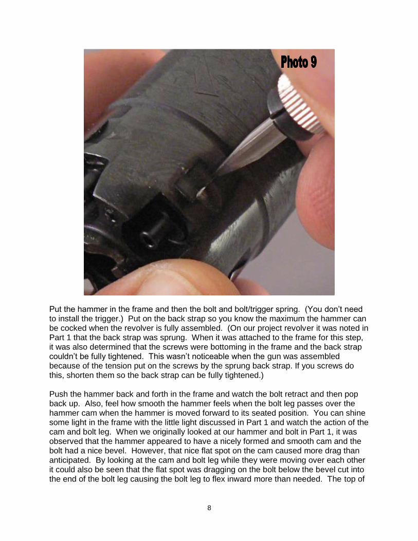
The cylinders on our black powder revolver are soft. Thus, we can re-square the notches with a de-burring tool like that pictured in Part 1. Put the point of the tool in the bottom of the notch (on the same side as the burr) and make sure the side of the blade forms a 90 degree angle with the bottom of the notch and drag the blade along the notch. This may need to be done a couple of times, but the tool will cut the burr away and leave a nice clean square notch cut. Do this for all notches that have damage. On our project revolver, this was all six notches. Re-measure all of the notches; they should now be fairly uniform. If the middle measurement on any notch is still markedly smaller than the ends, you may need to remove a little more material with the de-burring tool. Now determine the smallest notch. On our project revolver, all the notches were between .152” and .154”. In Part 1 we marked the bolt with a black Sharpie. Keeping the cut as square as possible, stone this area down until it is .002” or .003” thinner than your smallest notch. On our project revolver the bolt was cut from .157” to .150”. Photo 9.
8
Put the hammer in the frame and then the bolt and bolt/trigger spring. (You don’t need to install the trigger.) Put on the back strap so you know the maximum the hammer can be cocked when the revolver is fully assembled. (On our project revolver it was noted in Part 1 that the back strap was sprung. When it was attached to the frame for this step, it was also determined that the screws were bottoming in the frame and the back strap couldn’t be fully tightened. This wasn’t noticeable when the gun was assembled because of the tension put on the screws by the sprung back strap. If you screws do this, shorten them so the back strap can be fully tightened.) Push the hammer back and forth in the frame and watch the bolt retract and then pop back up. Also, feel how smooth the hammer feels when the bolt leg passes over the hammer cam when the hammer is moved forward to its seated position. You can shine some light in the frame with the little light discussed in Part 1 and watch the action of the cam and bolt leg. When we originally looked at our hammer and bolt in Part 1, it was observed that the hammer appeared to have a nicely formed and smooth cam and the bolt had a nice bevel. However, that nice flat spot on the cam caused more drag than anticipated. By looking at the cam and bolt leg while they were moving over each other it could also be seen that the flat spot was dragging on the bolt below the bevel cut into the end of the bolt leg causing the bolt leg to flex inward more than needed. The top of
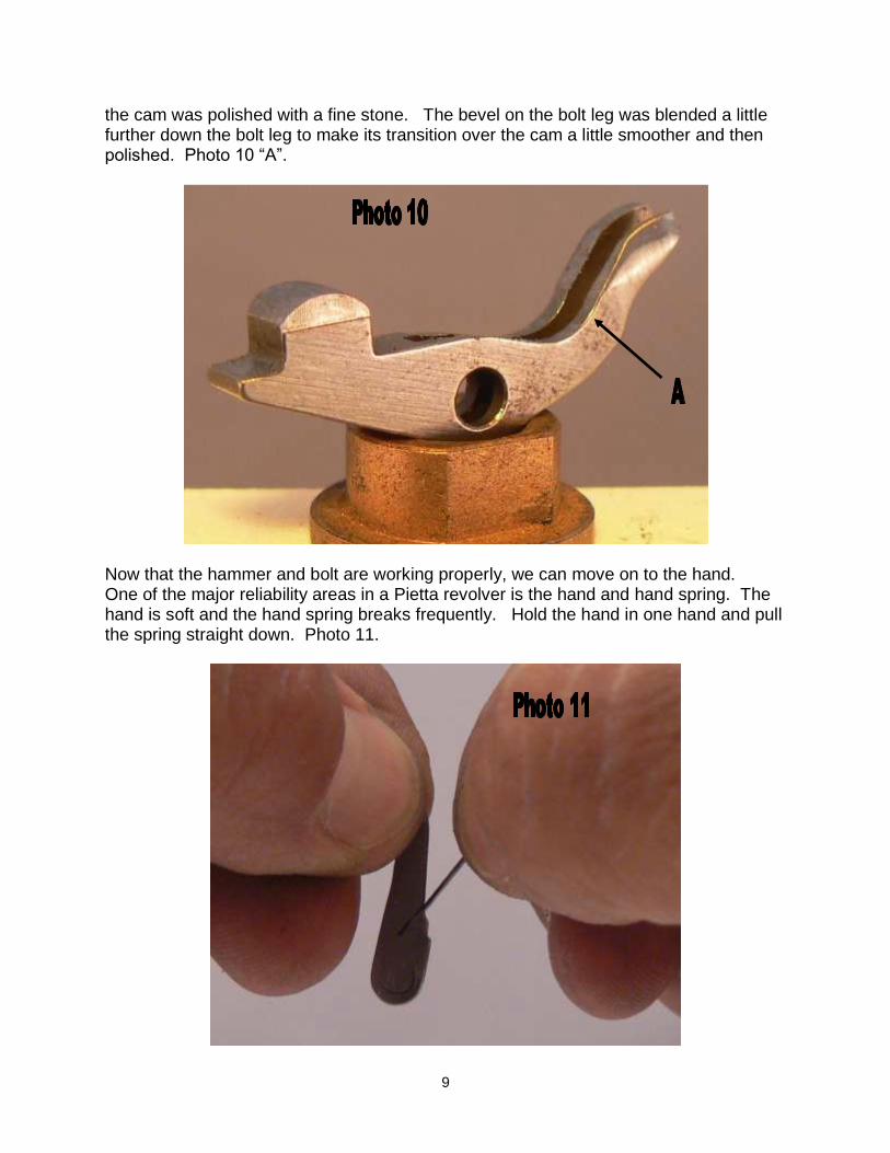
9
the cam was polished with a fine stone. The bevel on the bolt leg was blended a little further down the bolt leg to make its transition over the cam a little smoother and then polished. Photo 10 “A”.
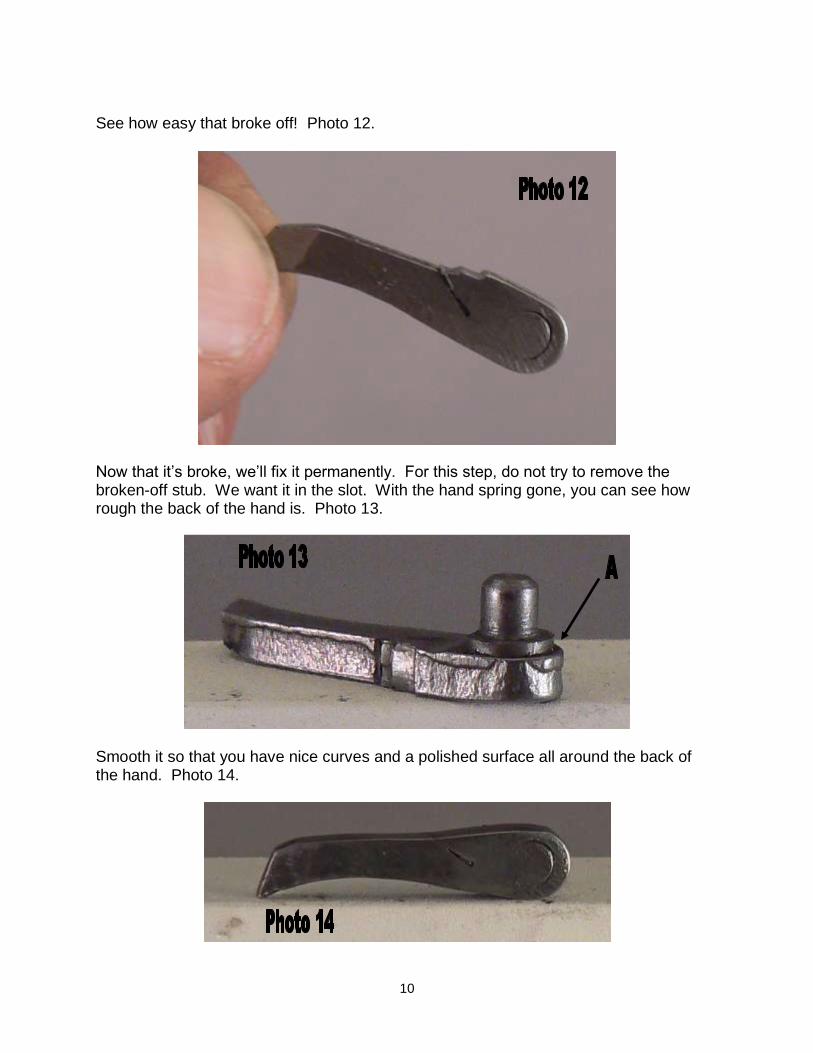
Now that the hammer and bolt are working properly, we can move on to the hand. One of the major reliability areas in a Pietta revolver is the hand and hand spring. The hand is soft and the hand spring breaks frequently. Hold the hand in one hand and pull the spring straight down. Photo 11.
10
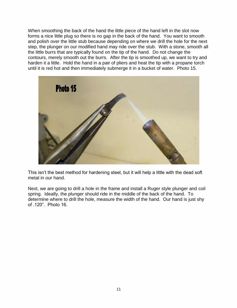
See how easy that broke off! Photo 12.
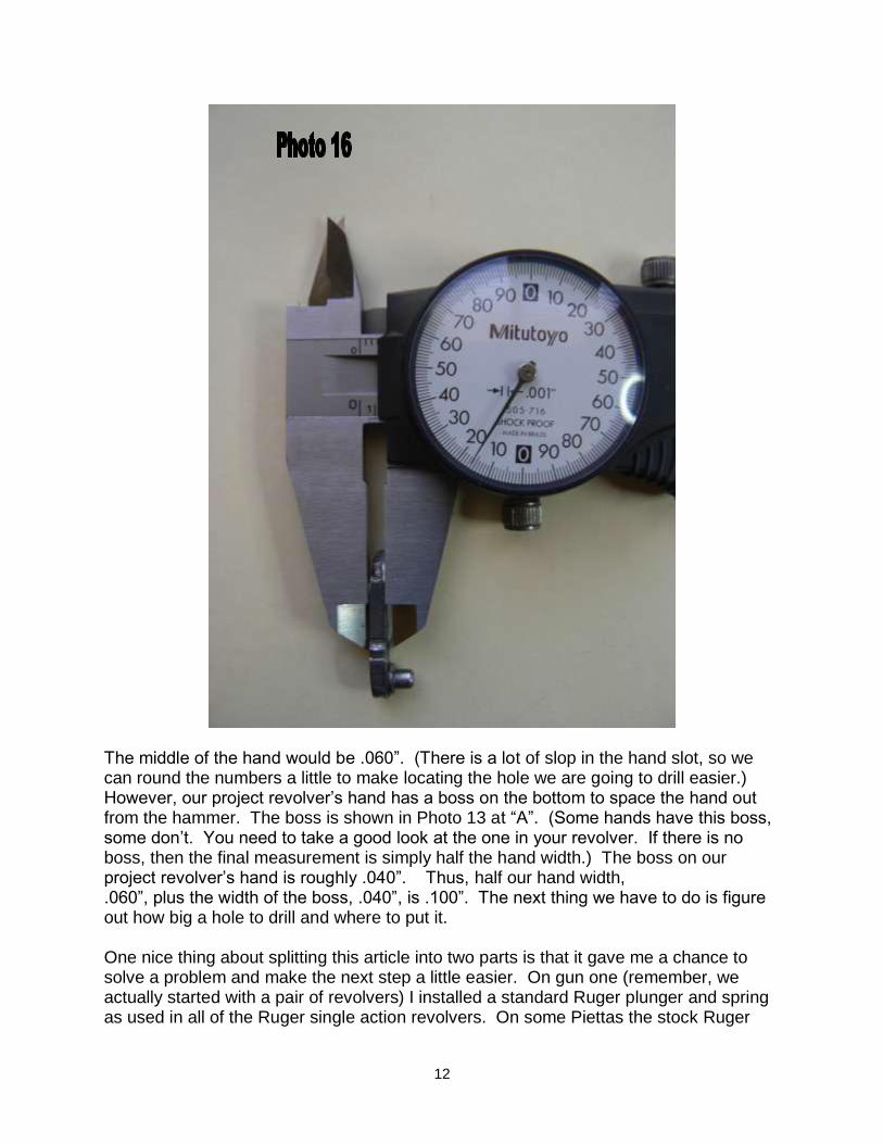
Now that it’s broke, we’ll fix it permanently. For this step, do not try to remove the broken-off stub. We want it in the slot. With the hand spring gone, you can see how rough the back of the hand is. Photo 13.
Smooth it so that you have nice curves and a polished surface all around the back of the hand. Photo 14.
11
When smoothing the back of the hand the little piece of the hand left in the slot now forms a nice little plug so there is no gap in the back of the hand. You want to smooth and polish over the little stub because depending on where we drill the hole for the next step, the plunger on our modified hand may ride over the stub. With a stone, smooth all the little burrs that are typically found on the tip of the hand. Do not change the contours, merely smooth out the burrs. After the tip is smoothed up, we want to try and harden it a little. Hold the hand in a pair of pliers and heat the tip with a propane torch until it is red hot and then immediately submerge it in a bucket of water. Photo 15.
This isn’t the best method for hardening steel, but it will help a little with the dead soft metal in our hand. Next, we are going to drill a hole in the frame and install a Ruger style plunger and coil spring. Ideally, the plunger should ride in the middle of the back of the hand. To determine where to drill the hole, measure the width of the hand. Our hand is just shy of .120”. Photo 16.
12
The middle of the hand would be .060”. (There is a lot of slop in the hand slot, so we can round the numbers a little to make locating the hole we are going to drill easier.) However, our project revolver’s hand has a boss on the bottom to space the hand out from the hammer. The boss is shown in Photo 13 at “A”. (Some hands have this boss, some don’t. You need to take a good look at the one in your revolver. If there is no boss, then the final measurement is simply half the hand width.) The boss on our project revolver’s hand is roughly .040”. Thus, half our hand width, .060”, plus the width of the boss, .040”, is .100”. The next thing we have to do is figure out how big a hole to drill and where to put it. One nice thing about splitting this article into two parts is that it gave me a chance to solve a problem and make the next step a little easier. On gun one (remember, we actually started with a pair of revolvers) I installed a standard Ruger plunger and spring as used in all of the Ruger single action revolvers. On some Piettas the stock Ruger
13
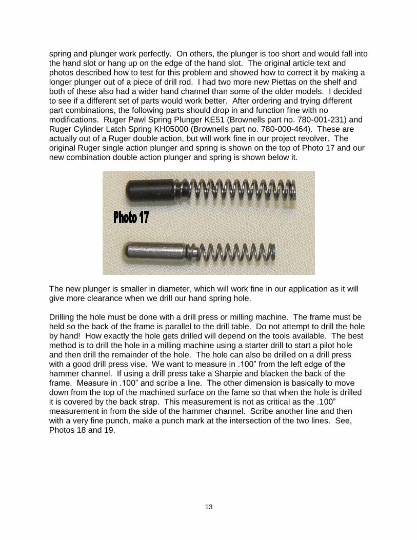
spring and plunger work perfectly. On others, the plunger is too short and would fall into the hand slot or hang up on the edge of the hand slot. The original article text and photos described how to test for this problem and showed how to correct it by making a longer plunger out of a piece of drill rod. I had two more new Piettas on the shelf and both of these also had a wider hand channel than some of the older models. I decided to see if a different set of parts would work better. After ordering and trying different part combinations, the following parts should drop in and function fine with no modifications. Ruger Pawl Spring Plunger KE51 (Brownells part no. 780-001-231) and Ruger Cylinder Latch Spring KH05000 (Brownells part no. 780-000-464). These are actually out of a Ruger double action, but will work fine in our project revolver. The original Ruger single action plunger and spring is shown on the top of Photo 17 and our new combination double action plunger and spring is shown below it.
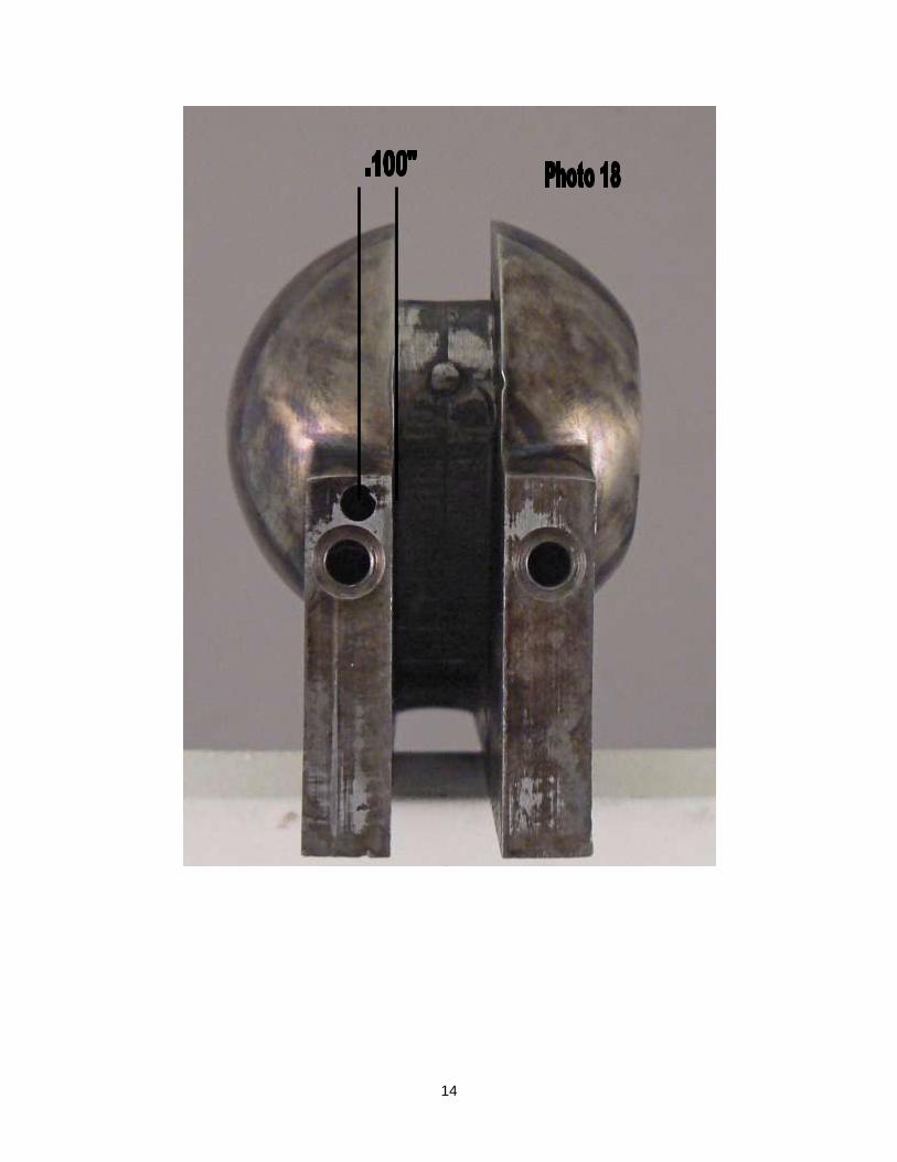
The new plunger is smaller in diameter, which will work fine in our application as it will give more clearance when we drill our hand spring hole. Drilling the hole must be done with a drill press or milling machine. The frame must be held so the back of the frame is parallel to the drill table. Do not attempt to drill the hole by hand! How exactly the hole gets drilled will depend on the tools available. The best method is to drill the hole in a milling machine using a starter drill to start a pilot hole and then drill the remainder of the hole. The hole can also be drilled on a drill press with a good drill press vise. We want to measure in .100” from the left edge of the hammer channel. If using a drill press take a Sharpie and blacken the back of the frame. Measure in .100” and scribe a line. The other dimension is basically to move down from the top of the machined surface on the fame so that when the hole is drilled it is covered by the back strap. This measurement is not as critical as the .100” measurement in from the side of the hammer channel. Scribe another line and then with a very fine punch, make a punch mark at the intersection of the two lines. See, Photos 18 and 19.
14
15
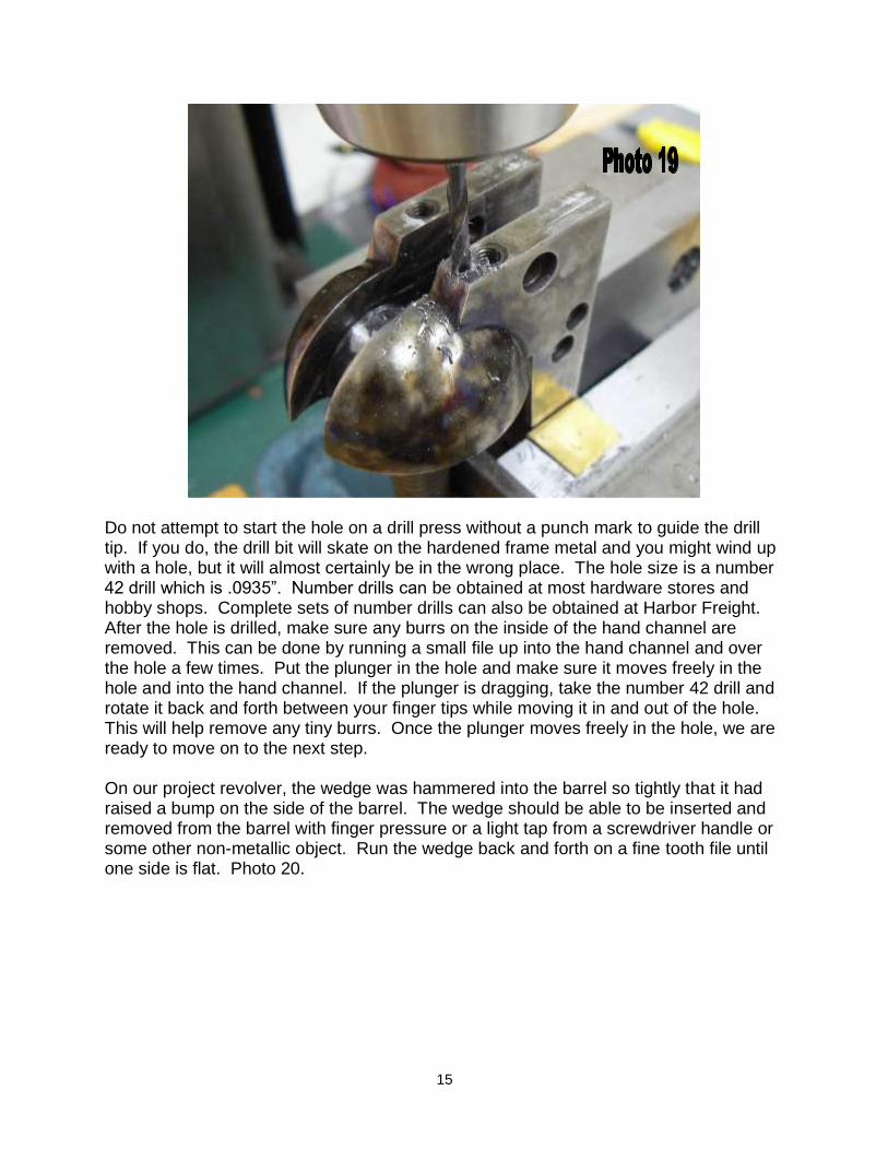
Do not attempt to start the hole on a drill press without a punch mark to guide the drill tip. If you do, the drill bit will skate on the hardened frame metal and you might wind up with a hole, but it will almost certainly be in the wrong place. The hole size is a number 42 drill which is .0935”. Number drills can be obtained at most hardware stores and hobby shops. Complete sets of number drills can also be obtained at Harbor Freight. After the hole is drilled, make sure any burrs on the inside of the hand channel are removed. This can be done by running a small file up into the hand channel and over the hole a few times. Put the plunger in the hole and make sure it moves freely in the hole and into the hand channel. If the plunger is dragging, take the number 42 drill and rotate it back and forth between your finger tips while moving it in and out of the hole. This will help remove any tiny burrs. Once the plunger moves freely in the hole, we are ready to move on to the next step. On our project revolver, the wedge was hammered into the barrel so tightly that it had raised a bump on the side of the barrel. The wedge should be able to be inserted and removed from the barrel with finger pressure or a light tap from a screwdriver handle or some other non-metallic object. Run the wedge back and forth on a fine tooth file until one side is flat. Photo 20.
16
Then put the wedge on a stone and polish that side until it is smooth. Photo 21.
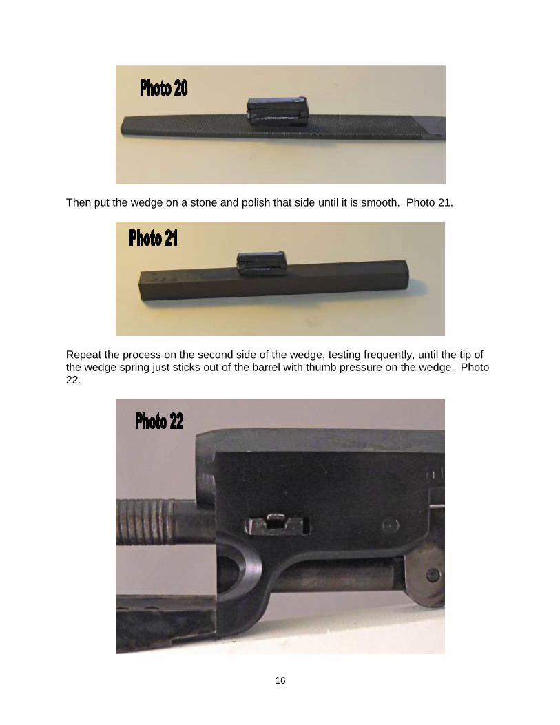
Repeat the process on the second side of the wedge, testing frequently, until the tip of the wedge spring just sticks out of the barrel with thumb pressure on the wedge. Photo 22.
17
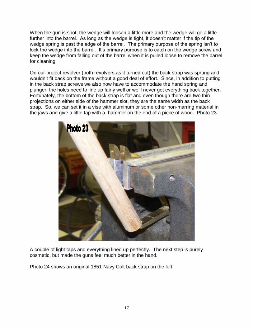
When the gun is shot, the wedge will loosen a little more and the wedge will go a little further into the barrel. As long as the wedge is tight, it doesn’t matter if the tip of the wedge spring is past the edge of the barrel. The primary purpose of the spring isn’t to lock the wedge into the barrel. It’s primary purpose is to catch on the wedge screw and keep the wedge from falling out of the barrel when it is pulled loose to remove the barrel for cleaning. On our project revolver (both revolvers as it turned out) the back strap was sprung and wouldn’t fit back on the frame without a good deal of effort. Since, in addition to putting in the back strap screws we also now have to accommodate the hand spring and plunger, the holes need to line up fairly well or we’ll never get everything back together. Fortunately, the bottom of the back strap is flat and even though there are two thin projections on either side of the hammer slot, they are the same width as the back strap. So, we can set it in a vise with aluminum or some other non-marring material in the jaws and give a little tap with a hammer on the end of a piece of wood. Photo 23.
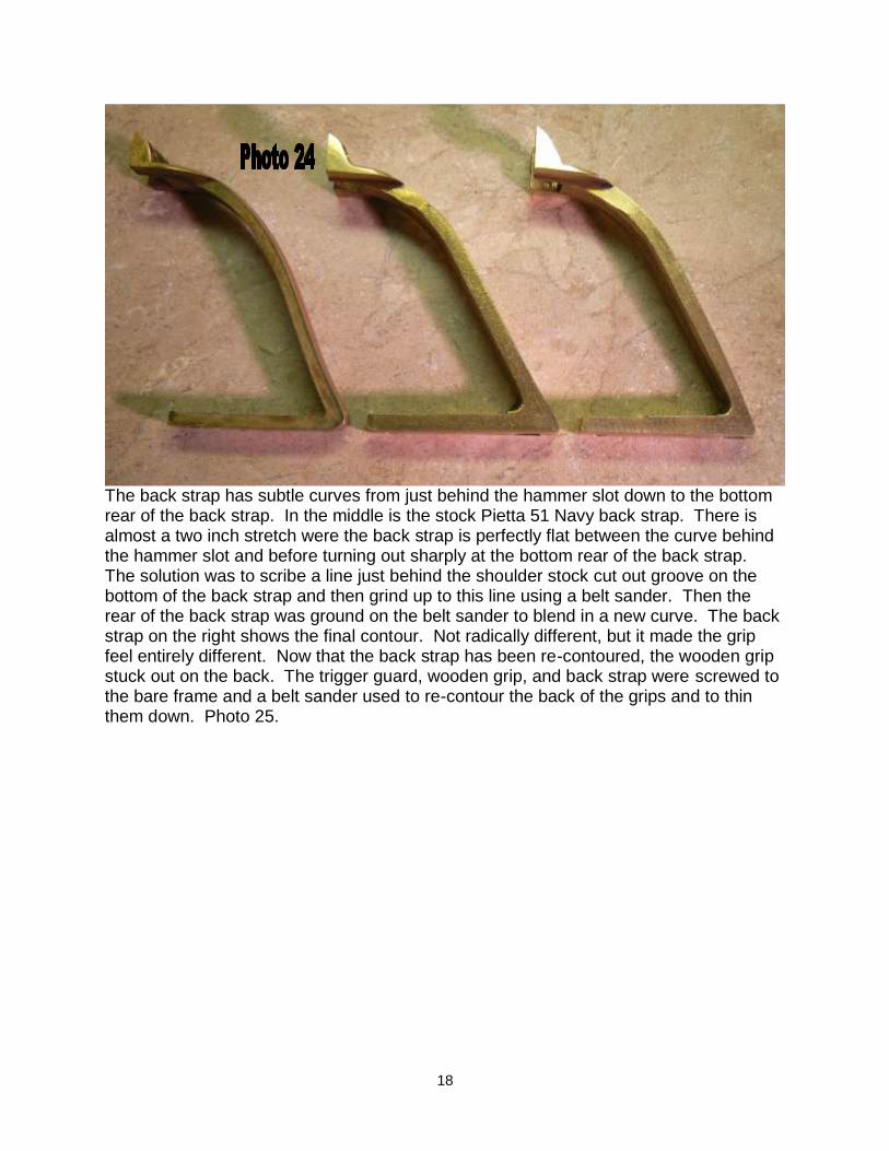
A couple of light taps and everything lined up perfectly. The next step is purely cosmetic, but made the guns feel much better in the hand. Photo 24 shows an original 1851 Navy Colt back strap on the left.
18
The back strap has subtle curves from just behind the hammer slot down to the bottom rear of the back strap. In the middle is the stock Pietta 51 Navy back strap. There is almost a two inch stretch were the back strap is perfectly flat between the curve behind the hammer slot and before turning out sharply at the bottom rear of the back strap. The solution was to scribe a line just behind the shoulder stock cut out groove on the bottom of the back strap and then grind up to this line using a belt sander. Then the rear of the back strap was ground on the belt sander to blend in a new curve. The back strap on the right shows the final contour. Not radically different, but it made the grip feel entirely different. Now that the back strap has been re-contoured, the wooden grip stuck out on the back. The trigger guard, wooden grip, and back strap were screwed to the bare frame and a belt sander used to re-contour the back of the grips and to thin them down. Photo 25.

19
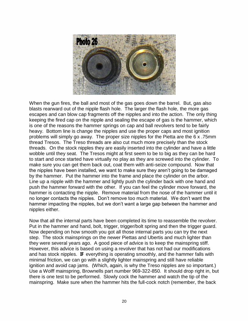
After the rough contours were cut-in a Black and Decker “Mouse” sander (a small orbital sander) was used to smooth the wood and remove the deep scratches from the back strap. Be careful not to mar the trigger guard as it is fine as is. After the grips were sanded smooth they were removed and paint remover used to remove the rest of the finish. After the wood was stripped and dried, a few coats of Birchwood Casey Tru-Oil stock finish was applied. No stain was needed, the wood looked great with just the application of the stock finish. While that was drying the back strap was polished with a small buffing wheel and compound from Sears. Shined up great. Had a few imperfections left over from the belt sanding, but after its been shot in a few matches no one will ever notice. Now comes one of the most important steps in our tune-up. More problems and frustration with cap and ball revolvers arise from misfires, caps falling off nipples, caps that are too tight to seat on the nipples, and cap fragments jamming the gun than all other issues combined. No matter how reliable the mechanicals may be and no matter how smooth the action, all of this is of no consequence if the gun will not fire reliably. There are always individuals who claim to have perfect performance from stock nipples and any brand of cap they can find at the local firearms emporium. Those circumstances, however, are few and far between. There is only one sure fire way to address ignition and cap problems--the nipples must be consistent in size and the caps must fit properly. The best combination is Treso nipples and Remington #10 caps. No other combination comes close to the reliability of this set-up. Treso nipples are uniform in diameter and have a smooth polished finish. This alone could make the difference between success and failure in shooting your cap and ball revolver. Another big factor in favor of the Tresos is that the Treso’s flash hole is much smaller than a stock Italian nipple. See, Photo 26.
20
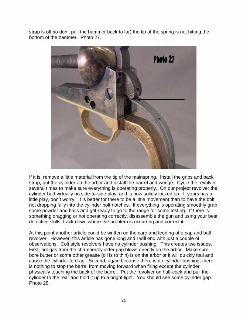
When the gun fires, the ball and most of the gas goes down the barrel. But, gas also blasts rearward out of the nipple flash hole. The larger the flash hole, the more gas escapes and can blow cap fragments off the nipples and into the action. The only thing keeping the fired cap on the nipple and sealing the escape of gas is the hammer, which is one of the reasons the hammer springs on cap and ball revolvers tend to be fairly heavy. Bottom line is change the nipples and use the proper caps and most ignition problems will simply go away. The proper size nipples for the Pietta are the 6 x .75mm thread Tresos. The Treso threads are also cut much more precisely than the stock threads. On the stock nipples they are easily inserted into the cylinder and have a little wobble until they seat. The Tresos might at first seem to be to big as they can be hard to start and once started have virtually no play as they are screwed into the cylinder. To make sure you can get them back out, coat them with anti-seize compound. Now that the nipples have been installed, we want to make sure they aren’t going to be damaged by the hammer. Put the hammer into the frame and place the cylinder on the arbor. Line up a nipple with the hammer and lightly push the cylinder back with one hand and push the hammer forward with the other. If you can feel the cylinder move forward, the hammer is contacting the nipple. Remove material from the nose of the hammer until it no longer contacts the nipples. Don’t remove too much material. We don’t want the hammer impacting the nipples, but we don’t want a large gap between the hammer and nipples either. Now that all the internal parts have been completed its time to reassemble the revolver. Put in the hammer and hand, bolt, trigger, trigger/bolt spring and then the trigger guard. Now depending on how smooth you got all those internal parts you can try the next step. The stock mainsprings on the newer Piettas and Ubertis and much lighter than they were several years ago. A good piece of advice is to keep the mainspring stiff. However, this advice is based on using a revolver that has not had our modifications and has stock nipples. IF everything is operating smoothly, and the hammer falls with minimal friction, we can go with a slightly lighter mainspring and still have reliable ignition and avoid cap jams. (Which, again, is why the Treso nipples are so important.) Use a Wolff mainspring, Brownells part number 969-322-850. It should drop right in, but there is one test to be performed. Slowly cock the hammer and watch the tip of the mainspring. Make sure when the hammer hits the full-cock notch (remember, the back
21
strap is off so don’t pull the hammer back to far) the tip of the spring is not hitting the bottom of the hammer. Photo 27.
If it is, remove a little material from the tip of the mainspring. Install the grips and back strap, put the cylinder on the arbor and install the barrel and wedge. Cycle the revolver several times to make sure everything is operating properly. On our project revolver the cylinder had virtually no side-to-side play, and is now solidly locked up. If yours has a little play, don’t worry. It is better for there to be a little movement than to have the bolt not dropping fully into the cylinder bolt notches. If everything is operating smoothly grab some powder and balls and get ready to go to the range for some testing. If there is something dragging or not operating correctly, disassemble the gun and using your best detective skills, track down where the problem is occurring and correct it. At this point another article could be written on the care and feeding of a cap and ball revolver. However, this article has gone long and I will end with just a couple of observations. Colt style revolvers have no cylinder bushing. This creates two issues. First, hot gas from the chamber/cylinder gap blows directly on the arbor. Make sure bore butter or some other grease (oil is to thin) is on the arbor or it will quickly foul and cause the cylinder to drag. Second, again because there is no cylinder bushing, there is nothing to stop the barrel from moving forward when firing except the cylinder physically touching the back of the barrel. Put the revolver on half-cock and pull the cylinder to the rear and hold it up to a bright light. You should see some cylinder gap. Photo 28.
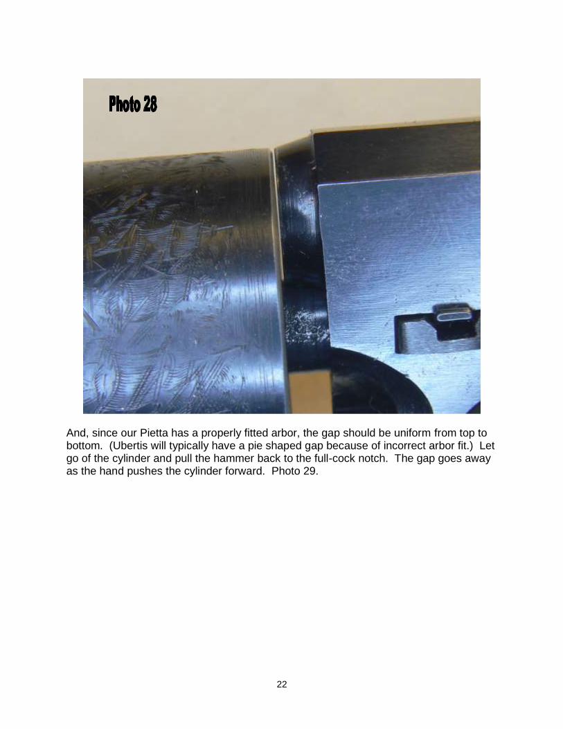
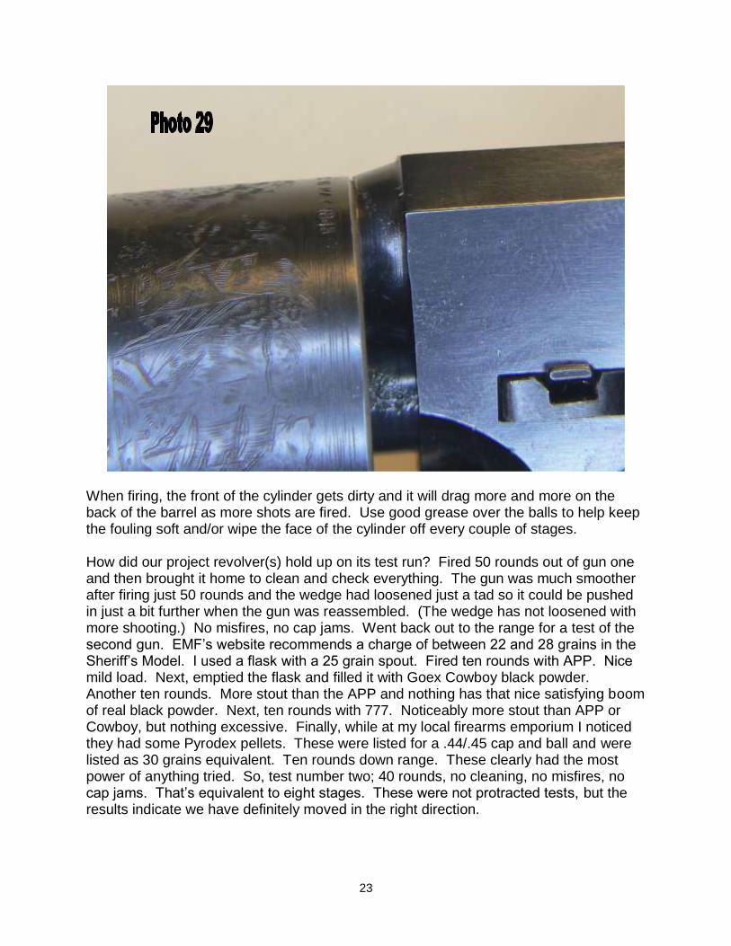
22
And, since our Pietta has a properly fitted arbor, the gap should be uniform from top to bottom. (Ubertis will typically have a pie shaped gap because of incorrect arbor fit.) Let go of the cylinder and pull the hammer back to the full-cock notch. The gap goes away as the hand pushes the cylinder forward. Photo 29.
23
When firing, the front of the cylinder gets dirty and it will drag more and more on the back of the barrel as more shots are fired. Use good grease over the balls to help keep the fouling soft and/or wipe the face of the cylinder off every couple of stages. How did our project revolver(s) hold up on its test run? Fired 50 rounds out of gun one and then brought it home to clean and check everything. The gun was much smoother after firing just 50 rounds and the wedge had loosened just a tad so it could be pushed in just a bit further when the gun was reassembled. (The wedge has not loosened with more shooting.) No misfires, no cap jams. Went back out to the range for a test of the second gun. EMF’s website recommends a charge of between 22 and 28 grains in the Sheriff’s Model. I used a flask with a 25 grain spout. Fired ten rounds with APP. Nice mild load. Next, emptied the flask and filled it with Goex Cowboy black powder. Another ten rounds. More stout than the APP and nothing has that nice satisfying boom of real black powder. Next, ten rounds with 777. Noticeably more stout than APP or Cowboy, but nothing excessive. Finally, while at my local firearms emporium I noticed they had some Pyrodex pellets. These were listed for a .44/.45 cap and ball and were listed as 30 grains equivalent. Ten rounds down range. These clearly had the most power of anything tried. So, test number two; 40 rounds, no cleaning, no misfires, no cap jams. That’s equivalent to eight stages. These were not protracted tests, but the results indicate we have definitely moved in the right direction.