240260280.com240260280.com/tech/carbs/weber/docs/hammil/power tuning webers v1 (tex… · speedpro...
TRANSCRIPT

......... ....................... ................. ........... .. ..... ........ ... ............. : .............. .. ...... ... . :
. .
J
' .. ... .. ...... ..... . . , .. .... ... . .. .. .......
Des
THE PUBliSHER

Contents
Introduction & acknowledgements 7 Weber DCOE versus Dellorto
DHLA ............................... 8 Acknowledgements ........................ 13 Essential information & using this
book ........................................... 14 Essential information ...................... 14 Using this book ............................... 14
Chapter 1. Know your carburettor: stripdown & inspection .............. 15
Know your carburettor - major components ................................ 15
Chokes and auxiliary venturis ......... 15 Idle mixture adjusting screws .......... 16 Main jet, emulsion tube & air
corrector ..................................... 16 Progression hole inspection
covers ......................................... 18 Idle jet ............................................ 18 Accelerator pump jets ..................... 19 Accelerator pump ........................... 19 Aoats ............................................. 20 Needle & seat.. ............................... 21 Stripdown - general advice ............. 22 Cleaning components ..................... 22
4
Fuel enrichment devices - special Chapter 3. Fuel management, air note ............................................ 23 filters & ram tubes ..................... 59
Stripdown procedure ...................... 23 Fuel filters ....................................... 59 Fuel enrichment device - blocking Fuel lines (pipes) & fillings .............. 59
off discharge. holes (Weber Air filters ......................................... 60 only) ........................................... 28 Ram tubes (stacks) ......................... 61
Fuel pressure .................................. 62 Chapter 2. Rebuilding ................. .41 Needle valve & seat (Dellorto) ....... .41 Chapter 4. Choosing the compo-Floats & fulcrum pin (Dellorto) ...... .41 nents for your carburettor/s .......... 64 Fulcrum pin- checking .................. .41 Components - initial selection ......... 64
oats - checking ............................ .41 Choke size versus carburettor size ... 64 Floats & pin- fitting .... ................... 42 Choke size - selecting ..................... 65 Aoat level - setting (Dellorto) .......... 42 Idle jet - selecting ............................ 6 7 Top cover (Dellorto) ...................... .43 Idle jet codes (Weber) ..................... 68 Body components (Dellorto) ........... 46 Emission controlled Needle valve & seat (Weber) .......... 48 sidedraught Weber carburettors ... 68 Aoats & fulcrum pin (Weber) ......... 48 Idle jet codes (Dellorto) ................... 68 Fulcrum pin - checking ................... 48 Idle jet & air bleed components -
oats - checking ............................. 48 selection ...................................... 69 Aoats and fulcrum pin - filling ......... 49 Idle mixture and progression holes .. 70 Aoat level- setting (Weber) ............ 49 Idle screw adjustment procedure ..... 71 Late model (mid 1980s-on) Spanish Main jet - selection .......................... 71
built Webers with plastic floats ..... 50 Emulsion tube - selection ................ 71 Top cover (Weber) ......................... 52 Air corrector - selection ................... 73 Body components (Weber) ............. 53 Auxiliary venturi - selection ............. 7 4

J
Accelerator pump jet - selection ...... 75 Accelerator pump intake/discharge
valve ........................................... 77 Needle valve - selection .................. 77
Chapter 5. Manifold preparation & carburettor fitting ...................... 79
Intake manifold - checking & preparation .................................. 79
The importance of stud alignment ... 79 Carburettor - checking fit ................ 80 Anti-vibration mountings ................ 81 Carburettor/s - fitting to manifold .... 82
Chapter 6. Testing & set-up·'······· 85 Idle speed ....................................... 85 fuel level & needle valve operation -
checking ...................................... 85 Throttle - initial adjustment and
synchronization ........................... 86 Throttle aim fit 86 Throttle - initial setting (single
carburettor) ................................. 86 Throttle - initial set-up &
synchronization (multiple carburettors) ........ .................... 86
Idle mixture initial adjustment ....... 86 Throttle (linked throttle arm type) -
final synchronization .................... 89 Throttle (bar & pushrod type) - final
synchronization ........................... 91 Full throttle check ........................... 93 Idle jet alteration (fuel component). 93
Ignition timing - general .................. 94 Idle jets/air bleeds - final selection ... 95
Weber ......................................... 96 Dellorto ....................................... 97
Idle mixture screws - final setting ..... 98 'Idle by-pass' circuitry carburettors ... 99 Adjusting idle by-pass systems ...... 101 CO readings and air'fuel ratio
readings .................................... 101 Accelerator pump jets - final
selection .................................... 102
Chapter 7. Testing & problem solving ...................................... 1 03
Rolling road ( dyno) testing procedure .................................. 104
Track testing procedure 104 Solving problems - low to mid-range
~m ........................................... 1~
Solving problems- high ~m ......... 105 Weber- fuel leakage from fuel
enrichment device ..................... 105 Weber- adapting for off-road
applications ............................... 106 Return springs ............. ................ 108 Tuning by exhaust gas CO% ......... 108 Maintenance.: ..... : ......... ............... 108
Chapter 8. Jetting/setting examples .................................. 109
BMC/Rover A-Series 1275cc engine (Weber) .................................... 109
Ford 'Pinto' 2000cc SOHC standard
engine (Weber) ......................... 110 Ford 'Pinto' 2000cc SOHC standard
engine (Dellorto) ....................... 110 Vauxhall2000cc 16v engine
(Dellorto) ................................... 110 FordRS 2000cc SOHC Escort
(Weber) .................................... 111 Ford Sierra Cosworth 2000cc
(naturally aspirated)(Weber) ...... 111 BMC B-Series 1900cc MGB engine
(Weber) .................................... 111 Toyota 4A-GE 1600cc 16-valve MR2
engine (Weber) ......................... 111 MG 1940cc alloy 8 port Magnette
engine (Weber) •........................ 111 Ford 1600cc Crossflow erigirie
(Weber) ............................. ...... 112 Jaguar XK 3.8 litre engine
(Dellorto) ................................... 112 Ford 'Pinto' 2100cc engine fitted to a
Formula 27 sports car (Dellorto) 112 Ford Sierra Cosworth 2000cc racing
engine (Dellorto) ....................... 112 Ford 1760cc Crossflow engine
(Dellorto) ...................... , ............ 112 BMC/Rover." 1275cc A-series· engine
(Dellorto) ............•...................... 113
Glossary ofterms ....................•... 123 American/English glossary of
automotive terrn$ ....................... 123
Index ........................................... 126
Visit Veloce on the Web www.veloce.co.uk 5
Introduction & acknowledgements
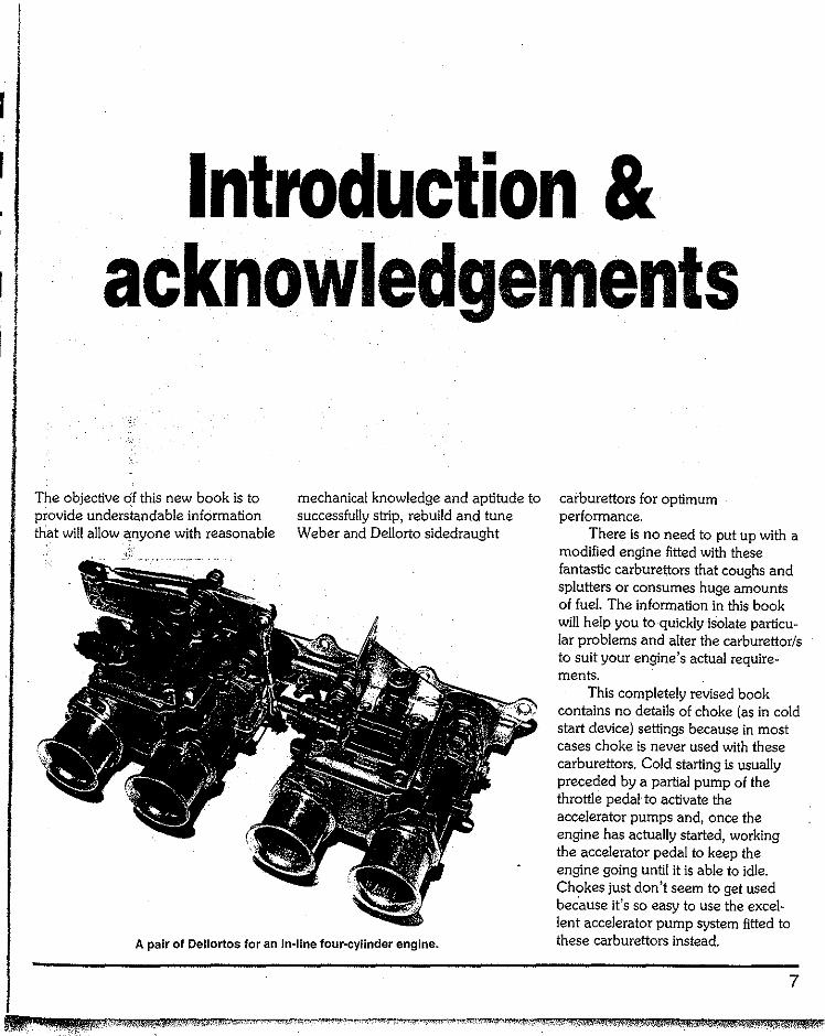
The objective of this new book is to provide understandable information that will allow anyone with reasonable
mechanical knowledge and aptitude to successfully strip, rebuild and tune Weber and Dellorto sidedraught
A pair of Dellortos for an in~line four-cylinder engine.
carburettors for optimum performance.
There is no need to put up with a modified engine fitted with these fantastic carburettors that coughs and splutters or consumes huge amounts of fuel. The information in this book will help you to quickly isolate particu-lar problems and alter the carburettor/s to suit your engine's actual require-ments.
This completely revised book contains no details of choke (as in cold start device) settings because in most cases choke is never used with these carburettors. Cold starting is usually preceded by a partial pump of the throttle pedal to activate the accelerator pumps and, once the engine has actually started, working the accelerator pedal to keep the engine going until it is able to idle. Chokes just don't seem to get used because it's so easy to use the excel-lent accelerator pump system fitted to these carburettors instead.
7
SPEEDPRO SERIES
Webers and Dellortos are truly excellent carburettors to work with. Even in this day and age of high technology there still is a place for 'simple' carburettors that give high performance while basically being bolt-on items. Webers and Dellortos meet these requirements and their future is assured. One thing is for sure, on a cost-for-cost basis, Webers and Dellortos (especially if good second-hand carburettors are purchased) can give unrivalled value for money.
There is an old adage "what looks right is right" and this certainly applies to Webers and Dellortos. They always "look the part" on an engine because they are the part and, no matter what the engine size or type, they can be made to go as well as they look.
Although it may appear that each and every iype and model of engine, and degree of modification, will require unique .carburettor settings, this is not the c<;tSe. It's very often the case that similar-engines require quite similar jetting, and very good approximations can be made by experienced mechanics without even seeing the engine. It is a fact that engines can be categorized to quite a large degree, which is why it's been possible to narrow down the Weber and Dellorto components listed in this book to those you are likely to need and use. This will save you time and money.
I hope that you find this book informative and a practical help in the quest to tune these carburettors to get the best possible performance from your car, allied to reasonable economy.
Weber DCOE versus Dellorto DHLA
Argument has raged for years about whether Weber or Dellorto carbs are better. No realistic comparison is
8
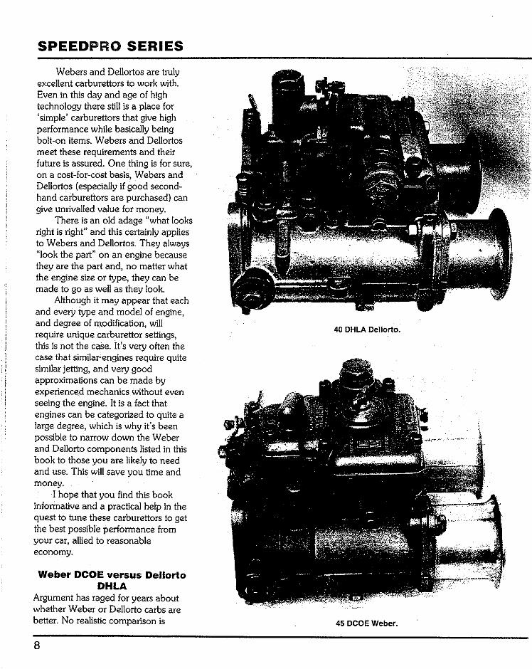
40 DHLA Dellorto.
45 DCOE Weber.
possible, however, unless all of the available adjustments have really been optimized on each carburettor type and on the same engine.
Fortunately, both carburettors are so good it doesn't really matter which manufacturer you choose. The main thing everyone needs to know is that you can buy either with absolute confidence in their performance, and that both can be tuned equally well. There are no really bad sidedraught Webers or Dellortos, but some are better than others. Both manufacturers have made emission versions of their respective carburettors, but these are not as good as the 'universal perlormance' versions, in terms of best possible all round accelerative and top end performance. When using secondhand Weber or Dellorto sidedraught carburettors you do need to know what you're buying by being able to identify exactly what is on offer. No competition engine should ever be equipped with emission type Dellorto or Weber 40mm carburettors.
Note that one of the quickest ways to establish at a glance whether a sidedraught Weber or Dellorto carburettor is suitable for high-performance use is to count the number of progression holes. Any carburettor which has two or three very small diameter (lmm/0.040inch) progression holes will have a rich progression phase, all other factors being equal. Carburettors with five quite large diameter (2mm/O. 080inch) progression holes will have a weaker progression phase, all other factors being equal.
Nothing of any consequence interchanges between the two makes of carburettor. The only thing common to both is that they will bolt on to the same intake manifold.
The design differences between the two carburettor makes show that
INTRODUCTION
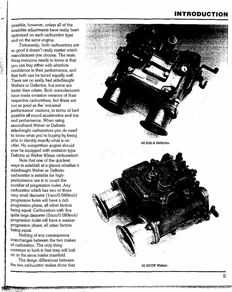
40 DHLA Dellorto.
45 DCOE Weber.
9

SPEEDPRO SERIES
Contents of a non·genu!ne aftermarket Oellorto repair kit for two carburettors.
..
The genuine Dellorto repair kit for two carburettors is more comprehensive than aftermarket ones.
their respective manufacturers have achieved the same objectives, but by different means. An example of this is the accelerator pump action. In both
10
cases the engine receives an identical amount of fuel but one carburettor has a diaphragm and the other a plunger. The Dellorto exhibits what can be
termed modern manufacturing tech-niques which modernize the original Weber carburettor concept to a small degree. !he Weber was designed and built in the days prior to reliable fuel resistant plastics and originally had brass floats, for instance.
The sidedraught Weber was undoubtedly the original in its DCO form of the early 1950s, and the overall concept and design the work of a genius (Edoardo Weber). The DCO series of sidedraught carburettors was superseded in the 1960s by the more affordable die cast sidedraught DCOE series.
Norman Seeney Ltd. (Tel: +44 (0)1527 892650, Fax: +44 (0)1527 893017) repairs and maintains the early sand cast DC03 and DCOA3 series carburettors, as fitted to Aston Martin, Ferrari, Maserati, Jaguar and Coventry Climax engines, for example. In fact, the company offers a worldwide repair and maintenance service for all early Weber racing carburettors. The most regular types of carburettor Norman Seeney services and repairs are: 38mm-40mm DC03, 42mm, 45mm, 48mm, 50mm and 58mm DC03, 58mm DCOA3 (six bolt flange), 40mm, 42mm, 45mm DCOA3 (four bolt flange). Others include the 48mm DOM, the 52mm DCO and the 36mm DOE.
There is no doubt that the racing success rate of cars equipped with these original sidedraught carburettors; and the fact that Dellorto didn't start making sidedraught carburettors until the late 1960s, contributed to Weber having the best known 'name'. Second-hand prices are generally higher for Webers even though the new price of each was similar. There are literally thousands of both types of sidedraught carburettor scattered around the world and millions of tuning parts sitting in tool boxes and
J
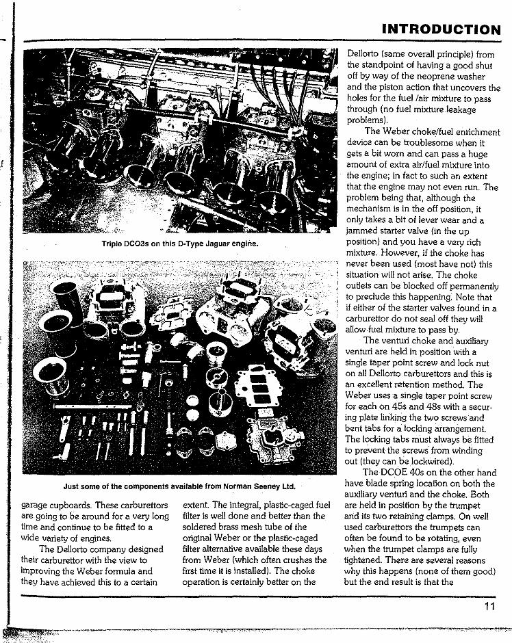
Triple DC03s on this D·Type Jaguar engirle.
Just some of the components available from Norman Seeney Ltd.
garage cupboards. These carburettors are going to be around for a very long time and continue to be fitted to a wide variety of engines.
The Dellorto company designed their carburettor with the view to improving the Weber formula and they have achieved this to a certain
extent. The integral, plastic-caged fuel filter is well done and better than the soldered brass mesh tube of the original Weber or the plastic-caged filter alternative available these days from Weber (which often crushes the first time it is installed). The choke operation is certainly better on the
INTRODUCTION
Dellorto (same overall principle) from the standpoint of having a good shut off by way of the neoprene washer and the piston action that uncovers the holes for the fuel /air mixture to pass through (no fuel mixture leakage problems).
The Weber choke/fuel enrichment device can be troublesome when it gets a bit worn and can pass a huge amount of extra air/fuel mixture into the engine; in fact to such an extent that the engine may not even run. The problem being that, although the mechanism is in the off position, it only takes a bit of lever wear and a jammed starter valve (in the up position) and you have a very rich mixture. However, if the choke has never been used (most have not) this situation will not arise. The choke outlets can be blocked off permanently to preclude this happening. Note that if either of the starter valves found in a carburettor do not seal off they will allow fuel mixture to pass by.
The venturi choke and auxiliary venturi are held in position with a single taper point screw and lock nut on all Dellorto carburettors and this is an excellent retention method. The Weber uses a single taper point screw for each on 45s and 48s with a secur-ing plate linking the two screws and bent tabs for a locking arrangement. The locking tabs must always be fitted to prevent the screws from winding out (they canbelockwired).
The DCOE 40s on the other hand have blade spring location on both the auxiliary venturi and the choke. Both are held in position by the trumpet and its two retaining clamps. On well used carburettors the trumpets can often be found to be rotating, even when the trumpet clamps are fully tightened. There are several reasons why this happens (none of them good) but the end result is that the
11
i
SPEEDPRO SERIES
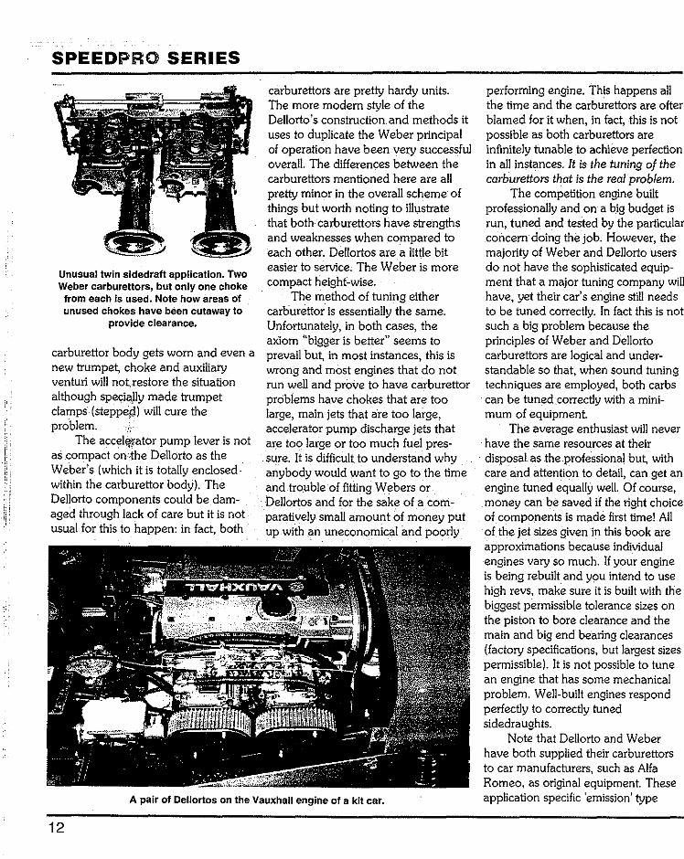
Unusual twin sidedraft application. Two Weber carburettors, but only one choke from each is used. Note how areas Of unused chokes have been cutaway to
provide clearance.
carburettor body gets worn and even a new trumpet, choke and auxiliary venturi will not.restore the situation although speci<;~lly made trumpet clamps (steppep) will cure the problem.
The accelfl!'ator pump lever is not as compact on'~he Dellorto as the Weber's (which it is totally enclosed· within the carburettor body). The Dellorto components could be dam-aged through lack of care but it is not usual for this to happen: in fact, both
carburettors are pretty hardy units. The more modern style of the Dellorto's construction. and methods it uses to duplicate the Weber principal of operation have been very successful overall. The differences between the carburettors mentioned here are all pretty minor in the overall scheme of things but worth noting to illustrate that both carburettors have strengths and weaknesses when compared to each other. Dellortos are a little bit easier to service. The Weber is more compact height-wise.
The method of tuning either carburettor is essentially the same. Unfortunately, in both cases, the axiom "bigger is better" seems to prevail but, in most instances, this is wrong and most engines that do not run well and prove to have carburettor problems have chokes that are too large, main jets that are too large, accelerator pump discharge jets that are too. large or too much fuel pres-sure. It is difficult to understand why anybody would want to go to the time and trouble of fitting Webers or Dellortos and for the sake of a com-paratively small amount of money put up with an uneconomical imd poorly
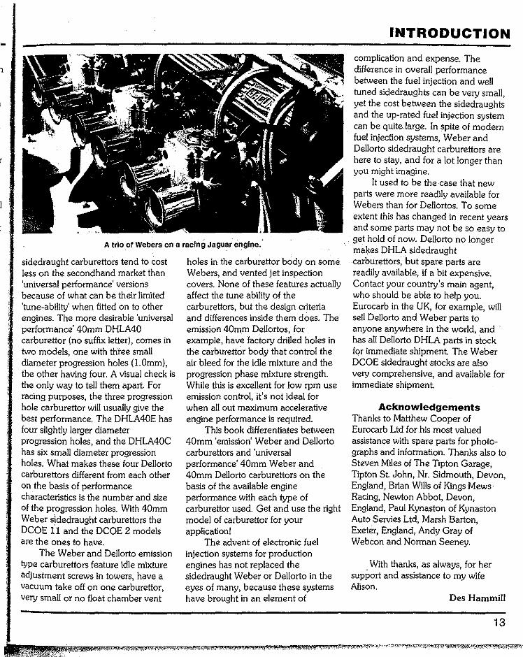
A pair of Dellortos on the Vauxhall engine of a kit car.
12
performing engine. This happens all the time and the carburettors are ofter blamed for it when, in fact, this is not possible as both carburettors are infinitely tunable to achieve perfection in all instances. It is the tuning of the carburettors that is the real problem.
The competition engine built professionally and on a big budget is run, tuned and tested by the particular concern doing the job. However, the majority of Weber and Dellorto users do not have the sophisticated equip-ment that a major tuning company will have, yet their car's engine still needs to be tuned correctly. In fact this is not such a big problem because the principles of Weber and Dellorto carburettors are logical and under-standable so that, when sound tuning techniques are employed, both carbs can be tuned correctly with a mini-mum of equipment.
The average enthusiast will never have the same resources at their disposal as the.professional but, with care and attention to detail, can get an engine tuned equally well. Of course, money can be saved if the right choice of components is made first time! All of the jet sizes given in this book are approximations because individual engines vary so much. If your engine is being rebuilt and you intend to use high revs, make sure it is built with the biggest permissible tolerance sizes on the piston to bore clearance and the main and big end bearing clearances (factory specifications, but largest sizes permissible). It is not possible to tune an engine that has some mechanical problem. Well-built engines respond perfectly to correctly tuned sidedraughts.
Note that Dellorto and Weber have both supplied their carburettors to car manufacturers, such as Alfa Romeo, as original equipment. These application specific 'emission' type
1
A trio of Webers on a racing Jaguar engine ..
sidedraught carburettors tend to cost less on the secondhand market ihan 'universal performance' versions because of what can be their limited 'tune-ability' when fitted on to other engines. The more desirable 'universal performance' 40mm DHLA40 carburettor (no suffix letter), comes in two models, one with three small diameter progression holes (l.Omm), the other having four. A visual check is the only way to tell them apart. For racing purposes, the three progression hole carburettor will usually give the best performance. The DHLA40E has four slightly larger diameter progression holes, and the DHLA40C has six small diameter progression holes. What makes these four Dellorto carburettors different from each other on the basis of performance characteristics is the number and size of the progression holes. With 40mm Weber sidedraught carburettors the DCOE ll and the DCOE 2 models are the ones to have.
The Weber and Dellorto emission type carburettors feature idle mixture adjustment screws in towers, have a vacuum take off on one carburettor, very small or no float chamber vent
holes in the carburettor body on some Webers, and vented jet inspection covers. None of these features actually affect the tune ability of the carburettors, but the design criteria and differences inside them does. The emission 40mm Dellortos, for example, have factory drilled holes in the carburettor body that control the air bleed for the idle mixture and the progression phase mixture strength. While this is excellent for low rpm use emission control, it's not ideal for when all out maximum accelerative engine performance is required.
This book differentiates between 40mm 'emission' Weber and Dellorto carburettors and 'universal performance' 40mm Weber and 40mm Dellorto carburettors on the basis of the available engine performance with each type of carburettor used. Get and use the right model of carburettor for your application!
The advent of electronic fuel injection systems for production engines has not replaced the sidedraught Weber or Dellorto in the eyes of many, because these systems have brought in an element of
INTRODUCTION
complication and expense. The difference in overall performance between the fuel injection and well tuned sidedraughts can be very small, yet the cost between the sidedraughts and the up-rated fuel injection system can be quite large. In spite of modern fuel injection systems, Weber and Dellorto sidedraught carburettors are here to stay, and for a lot longer than you might imagine.
It used to be the case that new parts were more readily available for Webers than for Dellortos. To some extent this has changed in recent years and some parts may not be so easy to get hold of now. Dellorto no longer makes DHLA sidedraught carburettors, but spare parts are readily available, if a bit expensive. Contact your country's main agent, who should be able to help you. Eurocarb in the UK, for example, will sell Dellorto and Weber parts to anyone anywhere in the world, and has all Dellorto D HLA parts in stock for immediate shipment. The Weber DCOE sidedraught stocks are also very comprehensive, and available for immediate shipment.
Acknowledgements Thanks to Matthew Cooper of Eurocarb Ltd for his most valued assistance with spare parts for photo-graphs and information. Thanks also to Steven Miles of The Tipton Garage, Tipton St. John, Nr. Sidmouth, Devon, England, Brian Wills of Kings Mews· Racing, Newton Abbot, Devon, England, Paul Kynaston of Kynaston Auto Servies Ltd, Marsh Barton, Exeter, England, Andy Gray of Webcon and Norman Seeney.
With thanks, as always, for her support and assistance to my wife Alison.
Des Hammill
13

Essential information &
using this book ESSENTIAL !~FORMATION
This book contains information on practical procedures; however, this information is intended only for those with the qualifications, experience, tools and facilities to carry out the work in safety and with appropriately high levels of skill. Although the words Warning! (personal danger) and Caution! (danger of mechanical damage) are used throughout this book, be aware that we cannot possibly foresee every possibility of danger in every circumstance. Whenever working on a car or componen~ remember that your personal safety must ALWAYS be your FIRST consideration. The publisher, author, editors and retailer ofthis book cannot accept any responsibility for personal injury or mechaniCal damage which results from using this book, even if caused by errors or omissions in the
14
information given. If this disclaimer is unacceptable to you, please return the pristine book to your retailer who will refund the purchase price.
This book applies to all Weber DCOE series and Dellorto DHLA series sidedraft carburetors.
It is possible that changing carbu-retor specification will mean that your car no longer complies with exhaust emission control or other regulations in your state or country - check before you start work.
An increase in engine power and, therefore, performance, will mean that your car's braking and suspension systems will need to be kept in perfect condition and uprated as appropriate.
As these carburetors were built to metric measurements, these take priority in the text. !tis essential that you work with metric wrenches, but we would also advise you to use metric measurements if you can.
The vital importance of cleaning a part before working on it cannot be overstressed. ·It is equally important that your tools and working area are completely clean.
Use good quality tools and make sure they are precisely the right size for every job.
USING THIS BOOK
You'll find it helpful to read the whole book before you start work or give instructions to your contractor. This is because a modification or change in specification in one area will cause the need for changes in other areas. Get the whole picture so that you can finalize specification and component requirements (as far as possible) before any work begins.
This book has been written in American English; those in any doubt over terminology will find a glossary of terms at the back of the book.
1 f,
r
(
i
a
or
f
Chapter 1 Know your carburettor: stripdown & inspection
KNOW YOUR CARBURETTOR MAJOR COMPONENTS
The overall layout is almost identical for Webers and Dellortos. The principles of operation are so close that carburettors of this type couldn't really be designed any differently.
Chokes and auxiliary venturis On all carburettors the choke is fitted into the barrel bore first and then the auxiliary venturi.
Note: it is quite possible on the 45 and 48 DCOE to put the auxiliary venturi into the carburettor body the wrong way around. The engine will run quite satisfactorily at low rpm but will run lean as the revs rise. Always check to see that the auxiliary venturi
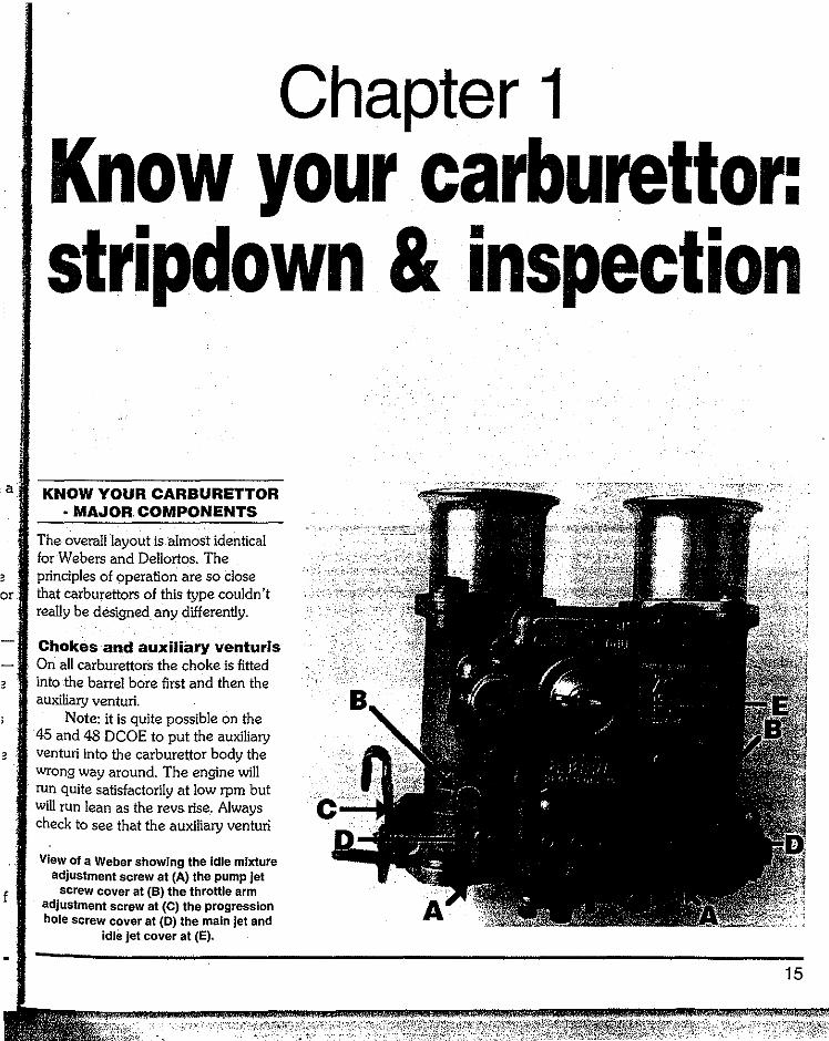
View of a Weber showing the Idle mixture adjustment screw at (A) the pump jet
screw cover at (B) the throttle arm adjustment screw at (C) the progression hole screw cover at (D) the main jet and
Idle jet cover at (E).
15
SPEEDPRO SERIES
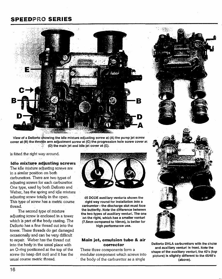
£b,owilna tl:le idle mixture adjusti.ng screw at (A) the pump jet screw arm adjustment screw at ·(C) the progression hole screw cover at (D) the main jet and idle jet cover at (E).
is fitted the right way around.
Idle mixture adjusting screws The idle mixture adjusting screws are in a similar position on both carburettors. There are two types of adjusting screws for each carburettor. One type, used by both Dellorto and Weber, has the spring and idle mixture adjusting screw totally in the open. This type of screw has a metric course thread.
The second type of mixture adjusting screw is enclosed in a tower which is part of the body casting. The Dellorto has a fine thread cut into the tower. These threads do get damaged occasionally and can be very difficult to repair. Weber has the thread cut into the body in the usual place with an 0-ring positioned at the top of the screw (to keep dirt out) and it has the usual course metric thread.
16
45 DCOE auxiliary venturis shown the right way round for installation into a
Carburetor- the discharge slot must face the butterfly. Note the difference between the two types of auxiliary venturi. The one oli the right, which has a smaller venturi (7.5mm compared to 10mm), is better for
high performance use.
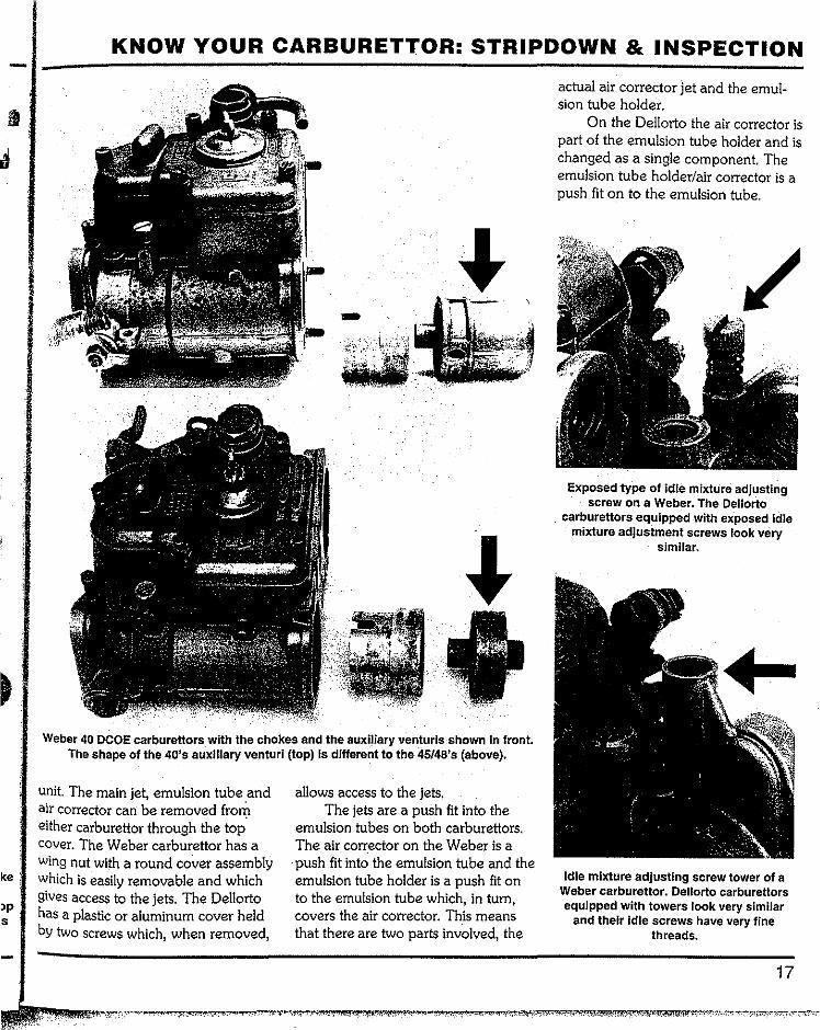
Main jet, emulsion tube & air corrector
These three components form a modular component which screws into the body of the carburettor as a single
Dellorto DHLA carburettors with the choke and auxiliary venturi in front. Note the
shape of the auxiliary venturi, the 40's (top picture) Is slightly different to the 45/4B's
(above).
ke:
s
KNOW YOUR CARBURETTOR: STRIPDOWN & INSPECTION
Weber 40 DCOE carburettors with the chokes and the auxiliary venturls shown in front. The shape of the 40's auxiliary venturi (top) is different to the 45/4B's (above).
unit The main jet, emulsion tube and air corrector can be removed from either carburettor through the top. cover. The Weber carburettor has a wing nut with a round cover assembly which is easily removable and which gives access to the jets. The Dellorto has a plastic or aluminum cover held by two screws which, when removed,
allows access to the jets. The jets are a push fit into the
emulsion tubes on both carburettors. The air corrector on the Weber is a
·push fit into the emulsion tube and the emulsion tube holder is a push fit on to the emulsion tube which, in tum, covers the air corrector. This means that there are two parts involved, the
actual air corrector jet and the emul-sion tube holder.
On the Dellorto the air corrector is part of the emulsion tube holder and is changed as a single component The emulsion tube holder/air corrector is a push fit on to the emulsion tube.
Exposed type of idle mixture adjusting screw on a Weber. The Dellorto
carburettors equipped with exposed idle mixture adjustment screws look very
similar.
Idle mixture adjusting screw tower of a Weber carburettor. Oellorto carburettors equipped with towers look very similar
and their Idle screws have very fine threads.
17
SPEEDPRO SERIES
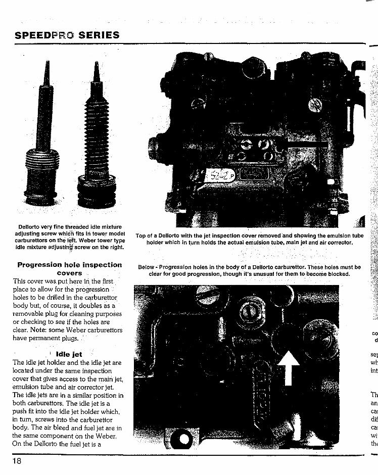
Dellorto very fine threaded idle mixture adjusting screw whiCh fits hi tower model carbUrettors on the Jeft. Weber tower type idle mixture ad justin~: screw on the right.
Progression hole inspection covers
This cover was put here in the first place to allow for the progression holes to be drilled in thecarburettor body but, of course, it doubles as a removable plug for cleaning purposes or checking to see if the holes are clear. Note: some Weber carburettors have permanent plugs ..
Idle jet The idle jet holder and the idle jet are located under the same inspection cover that gives access to the main jet, emulsion tube and air corrector jet. The idle jets are in a similar position in both carburettors. The idle jet is a push fit into the idle jet holder which, in turn, screws into the carburettor body. The air bleed and fuel jet are in the same component on the Weber. On the Dellorto the fuel jet is a
18
Top of a Oellorto with the jet inspection cover removed ·and showing the emulsion tube holder which in turn holds the actual emulsion tube, main jet and air corrector.
Below- Progression holes in the body of a Dellorto carburettor. These holes must be clear for good progression, though i_t's unusual for them to-become blocked.
-
co d
Th an
dif ca:
-
KNOW YOUR CARBURETTOR: STRIPDOWN & INSPECTION
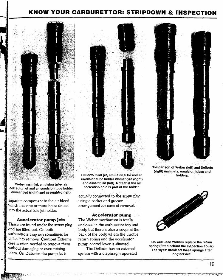
Weber main jet, emulsion tube, air corrector jet and an emulsion tube holder dismantled (rlght).and assembled (left).
separate component to the air bleed which has one or more holes drilled into the actual idle jet holder.
Accelerator pump jets These are found under the screw plug and are lifted out. On both carburettors they can sometimes be difficult to remove. Caution! Extreme care is often needed to remove them without damaging or even ruining them. On Dellortos the pump jet is
Dellorto main jet, emulsion. tube and.an emulsion tube holder dismantled (right) and assembled (left). Note that the air correction hole is part of the holder.
actually connected to the screw plug using a socket and groove arrangement for ease of removal.
Accelerator pump The Weber mechanism is totally enclosed in the carburettor top and body but there is also a cover at the back of the body where the throttle return spring and the accelerator pump control lever is situated.
The Dellorto has an external system with a diaphragm operated
Comparison of Weber (left) and Dellort0 (rlg!lt) main jets, emulsion tubes and
holders.
On well used Webers replace the return spring (fitted behind the Inspection cover).
The 'eyes' break off these springs after long service.
19

SPEEDPRO SERIES
Weber Idle jet and holder assembled (left) and separated (right).
Dellorto idle jet and holder assembled (left) and separated (right).
accelerator pump and lever system. This is all located underneath the carburettor.
20
W.eber carburettor with cover removed showing the position of the .idle jets.
Dellorto carburettor with cover removed and showing the position of the idle jets.
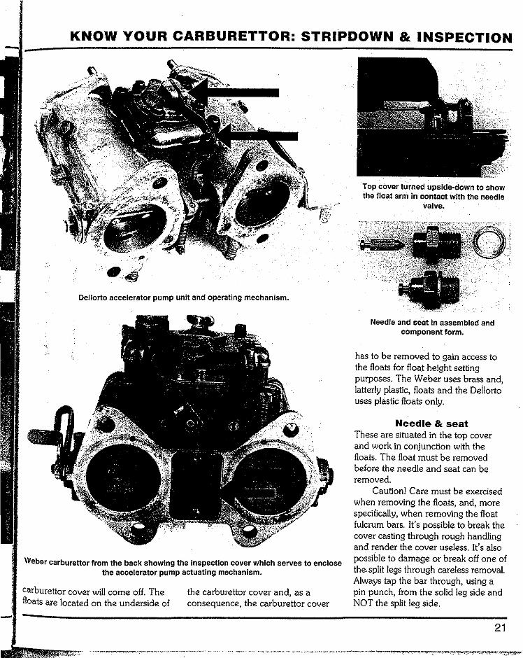
Floats The floats are located under the carburettor top cover on both
carburettors. Note: on the Weber carburettor the wing nut and round cover must be removed before the
w.
ca1 flo -
KNOW YOUR CARBURETTOR: STRIPDOWN & INSPECTION
Top cover turned upsld~down to show the float arm in contact with the needle
valve.
Dellorto accelerator pump unit and operating mechanism.
Weber carburettor from the back showing the Inspection cover which serves to enclose the accelerator pump actuating mechanism.
carburettor cover will come off. The floats are located on the underside of
the carburettor cover and, as a consequence, the carburettor cover
Needle and seat In assembled and component form.
has to be removed to gain access to the floats for float height setting purposes. The Weber uses brass and, latterly plastic, floats and the Dellorto uses plastic floats only.
Needle & seat These are situated in the top cover and work in conjunction with the floats. The float must be removed before the needle and seat can be removed.
Caution! Care must be exercised when removing the floats, and, more specifically, when removing the float fulcrum bars. It's possible to break the cover casting through rough handling and render the cover useless. It's also possible to damage or break off one of the. split legs through careless removal. Always tap the bar through, using a pin punch, from the solid leg side and NOT the split leg side.
21
SPEEDPRO SERIES
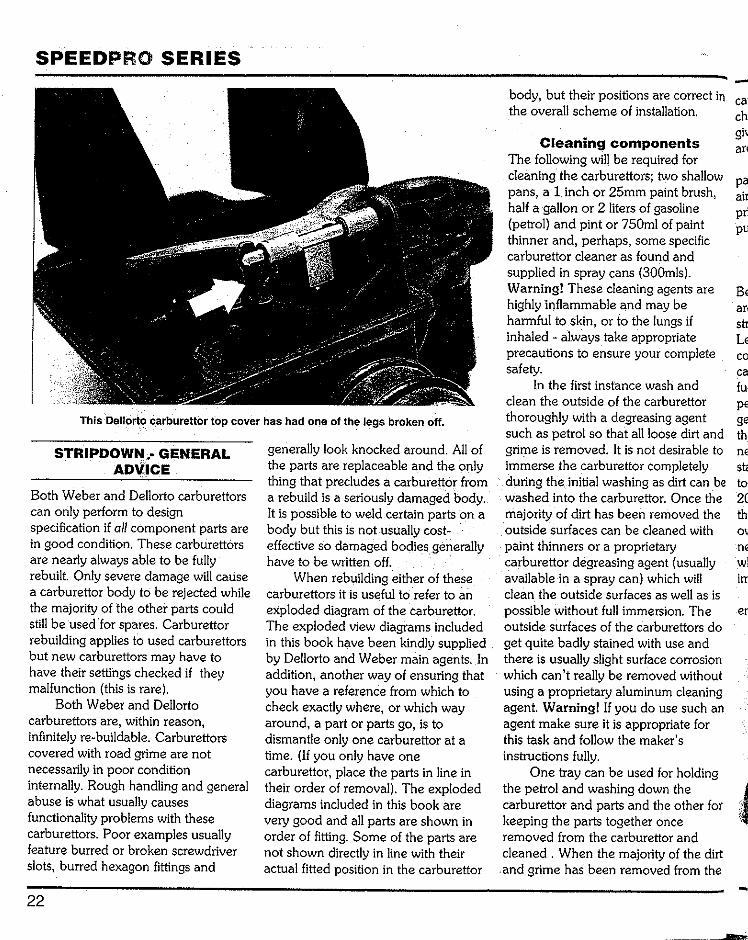
This·Dellorto Carburettor top cover has had one of the legs broken off.
STRIPDOWN GENERAL ADVICE
Both Weber and Dellorto carburettors can only perform to design specification if all component parts are in good condition. These carburettors are nearly always able to be fully rebuilt Only severe damage will cause a carburettor body to be rejected while the majority of the other parts could still be used ·for spares. Carburettor rebuilding applies to used carburettors but new carburettors may have to have their settings checked if they malfunction (this is rare).
Both Weber and Dellorto carburettors are, within reason, infinitely re-buildable. Carburettors covered with road grime are not necessarily in poor condition internally. Rough handling and general abuse is what usually causes functionality problems with these carburettors. Poor examples usually feature burred or broken screwdriver slots, burred hexagon fittings and
22
generally look knocked around. All of the parts are replaceable and the only thing that precludes a carburettor from a rebuild is a seriously damaged body. It is possible to weld certain parts on a body but this is not usually cost-effective so damaged bodies generally have to be written off.
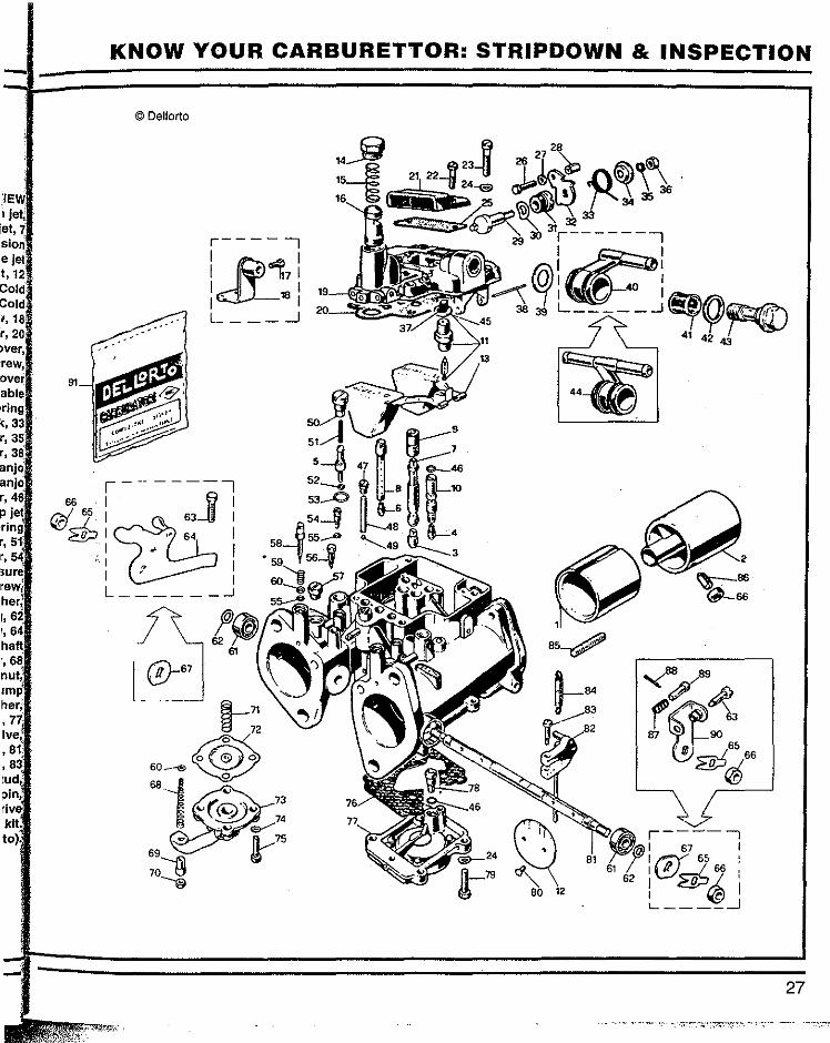
When rebuilding either of these carburettors it is useful to refer to an exploded diagram of the carburettor. The exploded view diagrams included in this book have been kindly supplied by Dellorto and Weber main agents. In addition, another way of ensuring that you have a reference from which to check exactly where, or which way around, a part or parts go, is to dismantle only one carburettor at a time. (If you only have one carburettor, place the parts in line in their order of removal). The exploded diagrams included in this book are very good and all parts are shown in order of fitting. Some of the parts are not shown directly in line with their actual fitted position in the carburettor
-body, but their positions are correct in cal the overall scheme of installation.
Cleaning components The following will be required for cleaning the carburettors; two shallow pa pans, a 1 inch or 25mm paint brush, air half a gallon or 2 liters of gasoline pri (petrol) and pint or 750ml of paint pu thinner and, perhaps, some specific carburettor cleaner as found and supplied in spray cans (300mls). Warning! These cleaning agents are Be highly inflammable and may be harmful to skin, or to the lungs if str inhaled always take appropriate Le precautions to ensure your complete co safety. ca
In the firstinstance wash and clean the outside of the carburettor pe thoroughly with a degreasing agent ge such as petrol so that all loose dirt and !hi grime is removed. lt is not desirable to ne immerse .the carburettor completely during the. initial washing as dirt can be to washed into the carburettor. Once the 2( majority of dirt has been removed the outside surfaces can be cleaned with paint thinners or a proprietary carburettor degreasing agent (usually wl available in a spray can) which will irr clean the outside surfaces as well as is possible without full immersion. The er outside surfaces of the carburettors do get quite badly stained with use and there is usually slight surface corrosion which can't really be removed without using a proprietary aluminum cleaning agent Warning! If you do use such an agent make sure it is appropriate for this task and follow the maker's instructions fully.
One tray can be used for holding the petrol and washing down the carburettor and parts and the other for keeping the parts together once removed from the carburettor and cleaned . When the majority of the dirt
.and grime has been removed from the -________
)W l,
e
:e
the he h
ly
is
do I on
ing
lirt
-
KNOW YOUR CARBURETTOR: &
carburettor and its components, change the fluid or use another tray to give all parts a final wash so that they are completely clean.
Caution! Never clean jets or passages with wire: use compressed air, nylon bristles or a piece of appro-priately thick fishing line for this purpose.
Fuel enrichment devices -special note
Because the fuel enrichment devices are never used, no details of their stripping down or assembly are given. Leave all of the fuel enrichment components installed in the carburettor. The Weber and Dellorto fuel enrichment devices work perfectly, of course, but never seem to get used. Most engines equipped with these carburettors that are well tuned need one pump (at the most) for starting and some throttle 'feathering' to keep them running for the first 10 to 20 seconds after cold start-up and then the engine will usually idle on its own account. This idle may not necessarily be up to the set idle speed while the engine is cold but will improve as the engine gets warm.
On the Weber carburettor the fuel enrichment device frequently causes
problems (excessive fuel delivery), so, rather than repair the mechanism, simply block off the outlet holes in the throttle bores. This is done by tapping the holes and screwing in a grub screw (use a locking agent and peen over the hole to prevent the grub screw unwinding and going into the engine), so that fuel cannot enter the engine via the enrichment holes. The Dellorto will only allow an over-enriched fuel supply to enter the engine if the fuel enrichment device washer fails, which it seldom does.
STRIPDOWN PROCEDURE
The carburettor can now be stripped. Remove the fuel pipe union using a six-point box end wrench (ring spanner). There is not all that much hexagon to grip onto (depth-wise) on the union bolt and it is fairly usual for the hexagon to be burred. (If the carburettors are on a manifold it is usual to loosen off the union bolt and the filter inspection bolt [on Webers] before removing a carburettor as they can often be very tight - this way there is more to hold firmly while the bolt is actually undone).
The fuel filter can now be re-moved and, in the case of the Weber,
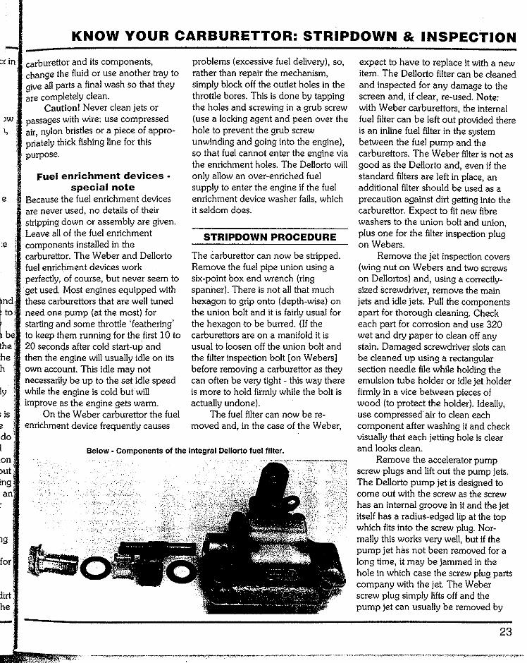
Below - Components of the integral Dellorto fuel filter.
expect to have to replace it with a new item. The Dellorto filter can be cleaned and inspected for any damage to the screen and, if clear, re-used. Note: with Weber carburettors, the internal fuel filter can be left out provided there is an inline fuel filter in the system between the fuel pump and the carburettors. The Weber filter is not as good as the Dellorto and, even if the standard filters are left in place, an additional filter should be used as a precaution against dirt getting into the carburettor. Expect to fit new fibre washers to the union bolt and union, plus one for the filter inspection plug on Webers.
Remove the jet inspection covers (wing nut on Webers and two screws on Dellortos) and, using a correctly-sized Screwdriver, remove the main jets and idle jets. Pull the components apart for thorough cleaning. Check each part for corrosion and use 320 wet and dry paper to clean off any stain. Damaged screwdriver slots can be cleaned up using a rectangular section needle file while holding the emulsion tube holder or idle jet holder firmly in a vice between pieces of wood (to protect the holder). Ideally, use compressed· air to clean each component after washing it and check visually that each jetting hole is clear and looks clean.
Remove the accelerator pump screw plugs and lift out the pump jets. The Dellorto pump jet is designed to come out with the screw as the screw has an internal groove in it and the jet itself has a radius-edged lip at the top which fits into the screw plug. Nor-mally this works very well, but if the pump jet has not been removed for a long time, it may be jammed in the hole in which case the screw plug parts company with the jet. The Weber screw plug simply lifts off and the pump jet can usually be removed by
23
SPEEDPRO SERIES
using pointed tweezers. On both carburettors, if the pump
jet is well and truly jammed in the hole a pair of long-nosed pliers can be modified (by grinding) so that the pump jet can be gripped and pulled out. The Weber pump jet has a small groove around the top edge for this very thing and the Dellorto has a radius-edged lip which can be used for the jet's extraction.
Remove the progression hole inspection screw plugs and check to see that there is no obvious dirt covering the holes. Use the correct sized screwdriver for the slot size.
Remove the idle mixture adjusting screws and check the tapered ends for any sign of damage: they should all look the same. It is .unusual to find a carburettor or a pair of carburettors with all screw end.s damaged so compare all sere\¥$ to each other.
Some Dellort,os have a tower and the idle mixture adjusting screw is located within this tower. A fine thread is cut into the tower and, because of this design, the threads are affected by dirt. collecting in the recess of the tower. The idle mixture adjusting screws can be quite tight to move, initially at least. Usually, once the carburettor body has been thoroughly washed and cleaned with compressed air, the idle mixture adjusting screws can be refitted without any problem. These threads can, unfortunately, become seriously damaged and be very difficult to repair. Note: there is something that can be done to prevent any damage occurring to the threads in the future. The idle mixture adjust-ing screws are not used often so the solution to this potential problem is to plug the holes after the engine has been tuned. The simplest way is to use silicone sealer. The plug of sealer can easily be removed when an adjust-ment needs to be made and new
24
sealer applied afterwards. The other way of doing this is to fit small plastic plugs that can be pushed in and then removed for idle mixture adjustment when necessary. Caution! If the engine is always getting dirty because of how the car is used, it is essential to seal the towers off.
If you cannot move the idle mixture screw, the screw's head has to be ground away. This is done with a high speed grinder fitted with a small ball-nosed cutter. Care must be taken so that the internal thread of the tower is not damaged any further. No attempt should be made to turn the screw out. Grind it all away and remove all traces of the screw material from the threads. Sometimes it is possible to do this and simply fit a new idle mixture adjusting screw, especially if a damaged screwdriver slot is the only reason for not being able to undo the screw. With the head removed the remaining portion of the screw is loose. Remove all metal particles.
Undo the screws from the top cover and, very c·arefully, remove it without any forcing of the floats to avoid damaging them. The Dellorto has a particularly close fit around the choke tower which necessitates that It be lifted vertically for a few millimeters. Turn the top over and, using a small pin punch, very carefully remove the fulcrum pin that holds the floats in position (Caution! - it's easy to break the split posts). Push the fulcrum pin out from the solid leg side, not the split leg side. Refit the fulcrum pin from the solid leg side too. There is a gasket between the carburettor body and the top (on both carburettors) which can only be removed and replaced while the floats are not fitted. It is always a good idea to replace this main gasket with a new one; essential if there is any sign of deterioration.
Shake the floats to make sure
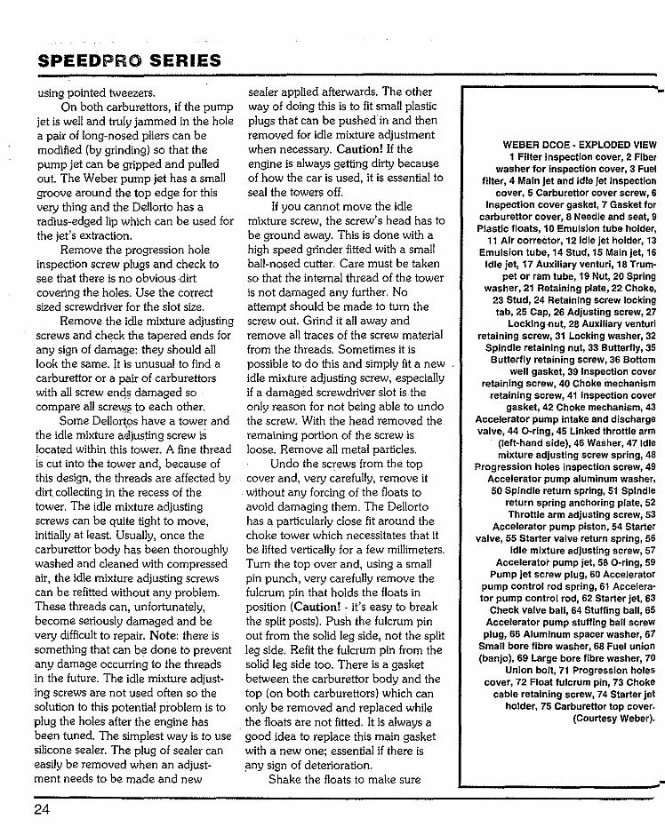
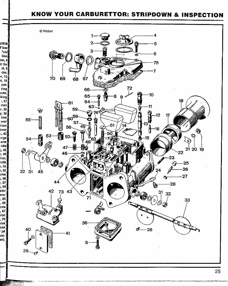
WEBER DCOE • EXPLODED VIEW 1 Filter inspection cover, 2 Fiber
washer for Inspection cover, 3 Fuel filter, 4 Main jet and idle jet inspection
cover, 5 Carburettor cover screw, 6 Inspection cover gasket, 7 Gasket for
carburettor cover, 8 Needle and seat, 9 Plastic floats, 10 Emulsion tube holder,
11 Air corrector, 121dle jet holder, 13 Emulsion tube, 14 Stud, 15 Main jet, 16
Idle jet, 17 Auxiliary venturi, 18 Trum-pet or ram tube, 19 Nut, 20 Spring
washer, 21 Retaining plate, 22 Choke, 23 Stud, 24 Retaining screw locking tab, 25 Cap, 26 Adjusting screw, 27
Locking ·nut, 28 Auxiliary venturi retaining screw, 31 Locking washer, 32
Spindle retaining nut, 33 Butterfly, 35 Butterfly retaining screw, 36 Bottom
well gasket, 39 Inspection cover retaining screw, 40 Choke mechanism
retaining screw, 41 Inspection cover gasket, 42 Choke mechanism, 43
Accelerator pump intake and discharge valve, 44 0-ring, 45 Linked throttle arm
(left-hand side), 46 Washer, 471dle mixture adjusting screw spring, 48
Progression holes inspection screw, 49 Accelerator pump aluminum washer, 50 Spindle return spring, 51 Spindle
return spring anchoring plate, 52 Throttle arm adjusting screw, 53
Accelerator pump piston, 54 Starter valve, 55 Starter valve return spring, 56
Idle mixture adjusting screw, 57 Accelerator pump jet, 58 0-ring, 59
Pump jet screw plug, 60 Accelerator pump control rod spring, 61 Accelera-tor pump control rod, 62 Starter jet, 63
Check valve ball, 64 Stuffing ball, 65 Accelerator pump stuffing ball screw
plug, 66 Aluminum spacer washer, 67 Small bore fibre washer, 68 Fuel union (banjo), 69 Large bore fibre washer, 70
Union bolt, 71 Progression holes cover, 72 Float fulcrum pin, 73 Choke
cable retaining screw, 74 Starter jet holder, 75 Carburettor top cover.
(Courtesy Weber).
M~er.,
KNOW YOUR CARBURETTOR: STRIPDOWN & INSPECTION
©Weber
21 20 19
25

SPEEDPRO SERIES
they contain no fuel and then check components usually come out easily their integrity by immersing them but the chokes can be difficult to completely in fuel and watching for air remove. If the chokes won't budge bubbles. Replace any faulty Dellorto refer to the information on choke float. Brass Weber floats can be removal given in the "Difficult Proce-repaired by soldering. Any soldered dures" section of this chapter. repair has to be reasonably small so Turn the carburettor over and that a minimum amount of weight is remove the bottom well cover. The added to the float assembly. If the main jets take their fuel out of here floats and frame look battered and and usually there is sediment and well used, replace them with new possibly some corrosion in the cover components. All Dellorto floats are and the underneath cavity of the plastic and deteriorate over time where carburettor body. The sediment and the aluminum of the frame has the corrosion must be washed and/or plastic moulded around it. The floats' carefully scraped away. main function is to maintain a constant On the Weber there are four fuel level under all conditions by screws holding the well cover on and opening and closing the needle valve. there is a gasket between the cover Worn fulcrum pins and float hinges and the body. Use a new gasket can cause fuel level to fluctuate. during the rebuild.
The needle and seat assembly On the Dellorto there are two can be unscrewed and should be parts to the bottom cover arrange-replaced with a new assembly unless men!. The accelerator pump housing you are working on a relatively new is below the well cover and has to be carburettor. The needles are prone to undone first. The accelerator pump wear on the very tip of the needle arm is part of the lower housing and, where it contacts the seat. Worn when the four screws are undone, the needles have an annular groove or housing can be moved aside while the indentation present all the way around accelerator pump arm is all still at-on the conical portion of the needle. !ached. Do not move or undo the two The wear on the seat is less apparent nuts that secure the pushrod from the as it is down the hole of the fitting. throttle spindle to the accelerator Replace the needle and seat as an pump actuating arm. The diaphragm assembly. Needles can be all metal or and spring can be removed from the rubber tipped. housing and inspected for wear or
Remove the trumpets, auxiliary damage. The well cover is secured by venturis and chokes. The Weber a further four screws and can be DCOE 40 has the choke and auxiliary undone and removed from the venturi retained by the trumpet and carburettor body. There is a gasket clamps. Some models of the 40 between the cover and the body. The DCOE have a different auxiliary accelerator pump intake valve is venturi which allows an air box to be screwed into the well cover housing. directly bolted on the carburettor This is a one-way valve only. without the usual clamps. The 45 and The Weber carburettor has the 48 DCOE Webers have a screw for accelerator pump intake and discharge each choke and auxiliary venturi and valve fitted into the bottom of the float the Dellorto has one nut and screw to chamber and this can be removed remove on the auxiliary venturi before with a large screwdriver. This valve
DELLORTO DHLA- EXPLODED VIEW 1 Choke, 2 Auxiliary venturi, 3 Main jet 4 Idle jet, 5 Pump jet, 6 Cold start jet, 7
Emulsion tube, 8 Cold start emulsion tube, 9 Air correction jet, 1 o Idle jet
housing, 11 Needle and seat, 12 Throttle butterfly, 13 Float, 14 Cold start tap screw, 15 Spring, 16 Cold start piston valve, 17 Set screw, 18
Cable clamp, 19 Float bowl cover, 20 Float bowl cover gask~t. 21 Vent cover,
22 Vent cover screw, 23 Cover screw, 24 Spring washer, 25 Vent cover
gaske~ 26 Bolt, 27 Washer, 28 Cable nut, 29 Actuator cam, 30 Spring
washer, 31 Sleeve, 32 Drive link, 33 Return spring, 34 Retaining washer, 35
Retaining clip, 36 Nut, 37 Filter, 38 Float fulcrum bar, 39 Washer, 40 Banjo (single), 41 Filter, 42 Washer, 43 Banjo bolt, 44 Banjo (double), 45 Washer, 46
O~ring; 47 Cap screw, 48 Pump jet spacer rod, 49 Pump jet metering
check ball, 50 Pump jet holder, 51 Spring, 52 0-ring, 53 Washer, 54
Bypass screw, 55 0-ring, 56 Pressure tap screw, 57 Progression tap screw,
58 Needle. valve, 59 Spring, SO Washer, 61 Throttle (butterfly) shaft bearing, 62 Spacer, 63 Throttle balance screw, 64
throttle drive arm, 65 Throttle shaft locknut, 66 Nut, 67 Thrust washer, 68
Spring, 69 Adjustment nut, 70 Locknut, 71 Diaphragm spring, 72 Pump
diaphragm, 73 Pump cover, 74 Washer, 75 Screw, 76 Pump housing gasket, 77
Pump housing, 78 Pump check valve, 79 Sprew, 80 Throttle plate screw, 81
Throttle shaft, 82 Pump drive lever, 83 Drive lever screw, 84 Spring, 85 Stud,
86 AV set screw, 87 Spring, 88 Clip pin, 89 Compression pin, 90 Throttle drive
arm, 91 Gasket and seal kit. (Courtesy Dellorto).
anything can be removed All of these can be quitet tight and difficult to26
KNOW YOUR CARBURETTOR: STRIPDOWN & INSPECTION
© Dellorto
18 L ____ _j
66 j
L ______
63 87
67 65 '
66
____ _j
27

SPEEDPRO SERIES
remove at times. The tapered-off top on this valve certainly reduces the size and strength of the screwdriver slot so it is important to use a screwdriver that fits the slot correctly in the first place. The Weber valve may have a small hole drilled in the side of it and this is part of the bleed-off for fuel during accelerator pump action. If there is a small hole in the side of the jet fuel escapes out of here back into the fuel bowl rather than being injected into the engine. This is part of the reason why Weber pump jets go up in 5s. The situation is alterable via the hole size found in the side of the jet. Valves are available that do not have a discharge hole. With the side hole blocked off or not present this accel-erator pump intake jet is a one-way valve.
The two screw plugs above the accelerator pump check balls and weights can be removed using a correct fitting screwdriver and the carburettor turnech.tpside-down so that the balls and weights fall out. (Use your large shallow tray for this pur-pose).
The Weber accelerator pump control rod is held in position by a brass retaining plate. To remove the accelerator pump control rod the retaining plate has two small indenta-tions in it that can be used for the removal of the plate. This is carried out using long-nosed pliers that have had the ends chamfered (by grinding) so that the tips of the pliers go to the bottom of each indentation in the retaining plate so that, when the pliers are used to squeeze the plate, they have the maximum amount of contact with the sides of the indentations. Caution! Do not squeeze too hard or the plate will distort. The indentations' main function is to centralize the spring found underneath the retaining plate.
28
Stripping down for cleaning, checking and, if necessary, replace-ment of the basic working parts of the carburettor/s is now complete. (The fuel enrichment mechanisms can remain installed as they are not used; the Dellorto mechanism is excellent and never causes problems).
The carburettor body can now be thoroughly washed and all scale or corrosion carefully scraped off the inside of the body and all sediment removed by washing in a shallow bath of clean gasoline (petrol). Clean out the throttle bores and remove any corrosion or surface roughness with very fine wet and dry paper. If the cleaning fluid becomes dirty and appears to be carrying particles, change it. With the body washed, and clean, dry it off using compressed air (100 psi or more).
FUEL ENRICHMENT DEVICE BLOCKING OFF DISCHARGE
HOLES (WEBER ONLY)
The Weber carburettor can have the discharge holes blocked off to eliminate air/fuel mixture leakage into the main tract during norrnal operation if the fuel enrichment mechanism proves to be faulty (often a problem with well-used Webers), or even if you just wish to prevent future problems. This is done by tapping with a 6mm by lmm pitch tap the outlet bore of each throttle bore for 12mm (0.5 inch) and installing suitable short grub screws into each one. The grub screws should be Allen-headed and must be securely fitted into the carburettor body. The tap used should be a taper tap or first tap which means that it will have a long lead in section. (This allows the thread of the grub screw to really wind into the thread cut into the body of the carburettor over a longer distance than if a plug tap was used).
A firmly wound in grub screw coated with a sealer/ locking agent will never move. Check to see that no part of the grub screw protrudes into the throttle bore.
Weber also produce competition only carburettors which do not have a fuel enrichment device/choke mechanism. These carburettors have thin pressed steel plate to neatly block off the back of the carburettor. Starter valves are omitted and there are no holes drilled for them. There are no holes drilled into the throttle bore either, so there's no possibility of fuel leakage.
INSPECTING COMPONENTS FOR WEAR AND .DAMAGE
Make the following checks as soon as the stripdown is complete so that you can order any parts which are not normally included in the basic repair kit. For each carburettor you'll need a new and full set of gaskets, 0-rings and, advisably, diaphragms, so check what is included in the basic repair kit package. A new needle valve assembly is recommended.
Weber & Dellorto Check to see if there is anything missing (see exploded view) from the carburettor/s you have dismantled. Check nuts for burring or damage. Check the fuel filter for damage. Check all screw heads for burring (clean them up or replace them). Ensure the floats are inspected for obvious damage and tested for leaks, their fulcrum pin checked for grooving or wear and the floats' hinge loops checked for looseness on the pin. Check needle and seat of the needle valve assembly for grooving around the point or tip (if grooved, replace both).
Check the throttle butterfly·
s {
(
t
s
l
(
ve
i
as ou
ir :la
ck kit
s,
'
KNOW YOUR CARBURETTOR: STRIPDOWN & INSPECTION
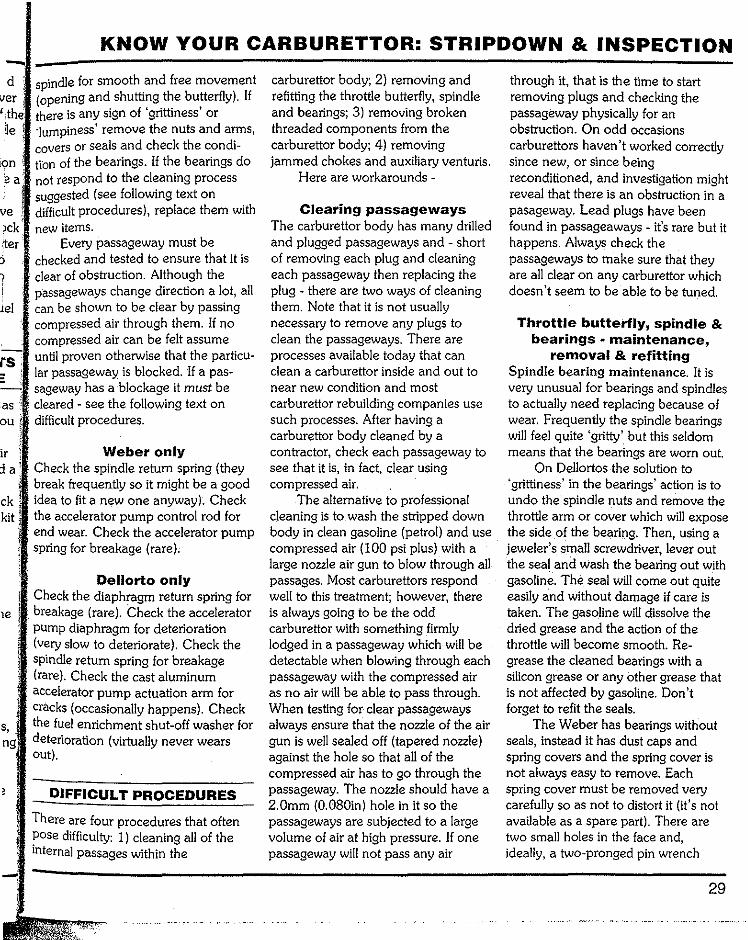
spindle for smooth and free movement (opening and shutting the butterfly). If there is any sign of 'grittiness' or 'lumpiness' remove the nuts and arms, covers or seals and check the condi-tibn of the bearings. If the bearings do not respond to the cleaning process suggested (see following text on difficult procedures), replace them with new items.
Every passageway must be checked and tested to ensure that it is clear of obstruction. Although the passageways change direction a lot, all can be shown to be clear by passing compressed air through them. If no compressed air can be felt assume until proven otherwise that the particu-lar passageway is blocked. If a pas-sageway has a blockage it must be cleared see the following text on difficult procedures.
Weber only Check the spindle return spring (they break frequently so it might be a good idea to fit a new one anyway). Check the accelerator pump control rod for end wear. Check the accelerator pump spring for breakage (rare).
Dellorto only Check the diaphragm return spring for breakage (rare). Check the accelerator pump diaphragm for deterioration (very slow to deteriorate). Check the spindle return spring for breakage (rare). Check the cast aluminum accelerator pump actuation arm for cracks (occasionally happens). Check the fuel enrichment shut-off washer for deterioration (virtually never wears out).
DIFFICULT PROCEDURES
There are four procedures that often pose difficulty: 1) cleaning all of the internal passages within the
carburettor body; 2) removing and refitting the throttle butterfly, spindle and bearings; 3) removing broken threaded components from the carburettor body; 4) removing jammed chokes and auxiliary venturis.
Here are workarounds
Clearing passageways The carburettor body has many drilled and plugged passageways and shori of removing each plug and cleaning each passageway then replacing the plug there are two ways of cleaning them. Note that it is not usually necessary to remove any plugs to clean the passageways. There are processes available today that can clean a carburettor inside and out to near new condition and most carburettor rebuilding companies use such processes. After having a carburettor body cleaned by a contractor, check each passageway to see that it is, in fact, clear using compressed air.
The alternative to professional cleaning is to wash the stripped down body in clean gasoline (petrol) and use compressed air (100 psi plus) with a large nozzle air gun to blow through all passages. Most carburettors respond well to this treatment; however, there is always going to be the odd carburettor with something firmly lodged in a passageway which will be detectable when blowing through each passageway with the compressed air as no air will be able to pass through. When testing for· clear passageways always ensure that the nozzle of the air gun is well sealed off (tapered nozzle) against the hole so that all of the compressed air has to go through the passageway. The nozzle should have a 2.0mm (0.080in) hole in it so the passageways are subjected to a large volume of air at high pressure. If one passageway will not pass any air
through it, that is the time to start removing plugs and checking the passageway physically for an obstruction. On odd occasions carburettors haven't worked correctly since new, or since being reconditioned, and investigation might reveal that there is an obstruction in a pasageway. Lead plugs have been found in passageaways - it's rare but it happens. Always check the passageways to make sure that they are all clear on any carburettor which doesn't seem to be able to be tuned.
Throttle butterfly, spindle & bearings maintenance,
removal & refitting Spindle bearing maintenance. It is very unusual for bearings and spindles to actually need replacing because of wear. Frequently the spindle bearings will feel quite 'gritty' but this seldom means that the bearings are worn out.
On Dellortos the solution to 'grittiness' in the bearings' action is to undo thespindle nuts and remove the throttle arm or cover which will expose the side of the bearing. Then, using a jeweler's small screwdriver, lever out the seal and wash the bearing out with gasoline. The seal will come out quite easily and without damage if care is taken. The gasoline will dissolve the dried grease and the action of the throttle will become smooth. He-grease the cleaned bearings with a silicon grease or any other grease that is not affected by gasoline. Don't forget to refit the seals.
The Weber has bearings without seals, instead it has dust caps and spring covers and the spring cover is not always easy to remove. Each spring cover must be removed very carefully so as not to distort it (it's not available as a spare part). There are two small holes in the face and, ideally, a two-pronged pin wrench
29
SPEEDPRO SERIES
A throttle spindle dust cap being removed from a Weber using circllp pliers (after the
body has been heated).
(spanner) is used to locate in these holes to facilitate a turning action. Suitably-sized snapring (circlip) pliers can be used to locate in the two holes and, using a smalL propane torch flame, apply localized heat to the bearing boss (carburettor body). With turning force beirrg applied to the spring cover bring the torch up to the
carburettor body. Once the heat expands the aluminum of the body the spring cover becomes loose and can be lifted out as it is twisted. The heat required is not great (hot to the touch will not distort the carburettor body). The dust cover will lift out and will usually have to be replaced with a new item as they do deteriorate with time and use.
Wash the bearings out and if the 'lumpy' action disappears, re-grease the bearings and replace the dust cap and cover. Replace the bearings with new items if this cleaning process fails to improve the throttle action.
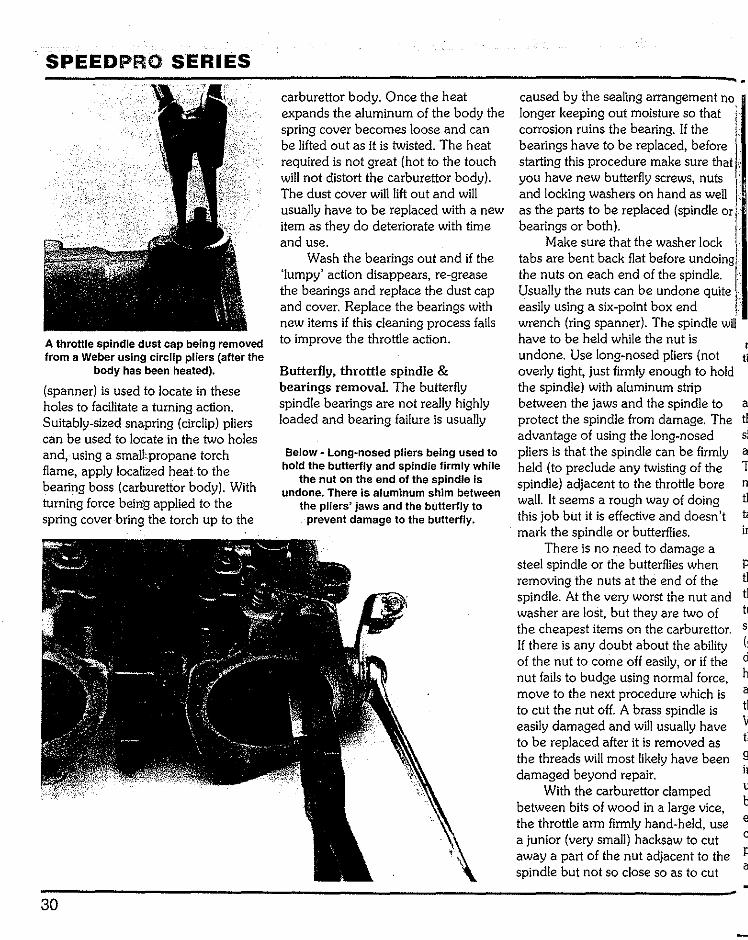
Butterfly, throttle spindle & bearings removal. The butterfly spindle bearings are not really highly loaded and bearing failure is usually
Below- Long~nosed pliers being used to hold the butterfly and spindle firmly while
the nut on the end of the spindle Is undone. There is aluminum shim between
the pliers' jaws and the butterfly to prevent damage to the butterfly.
caused by the sealing arrangement no longer keeping out moisture so that ' corrosion ruins the bearing. If the bearings have to be replaced, before starting this procedure make sure that you have new butterfly screws, nuts and locking washers on hand as well as the parts to be replaced (spindle or bearings or both).
Make sure that the washer lock tabs are bent back flat before undoing the nuts on each end of the spindle. Usually the nuts can be undone quite easily using a six-point box end wrench (ring spanner). The spindle willhave to be held while the nut is undone. Use long-nosed pliers (not overly tight, just firmly enough to hold the spindle) with aluminum strip between the jaws and the spindle to a protect the spindle from damage. The t1 advantage of using the long-nosed
r ti
si pliers is that the spindle can be firmly a held (to preclude any twisting of the T spindle) adjacent to the throttle bore wall. It seems a rough way of doing t1 this job but it is effective and doesn't mark the spindle or butterflies. ir
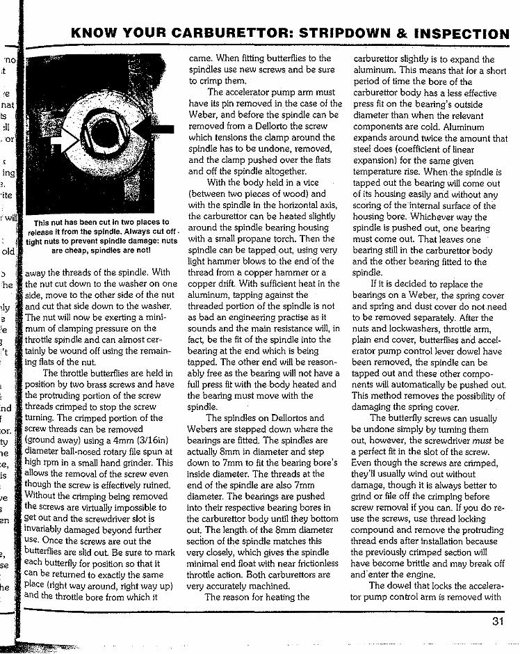
There is no need to damage a steel spindle or the butterflies when removing the nuts at the end of the spindle. At the very worst the nut and tl washer are lost, but they are two of the cheapest items on the carburettor. If there is any doubt about the ability of the nut to come off easily, or if the d nut fails to budge using normal force, h move to the next procedure which is a to cut the nut off. A brass spindle is tl easily damaged and will usually have V to be replaced after it is removed as tl the threads will most likely have been damaged beyond repair. ir
With the carburettor clamped u between bits of wood in a large vice, b the throttle arm firmly hand-held, use e a junior (very small) hacksaw to cut c away a part of the nut adjacent to the P spindle but not so close so as to cut a
old
:'t
nd f :or. ty 1e :e, is
se
he
KNOW YOUR CARBURETTOR: STRIPDOWN & INSPECTION
This nut has been cut in two places to release it from the spindle. Always cut off. tight nuts to prevent spindle damage: nuts
are cheap, spindles are notl
away the threads of the spindle, With the nut cut down to the washer on one side, move to the other side of the nut and cut that side down to the washer. The nut will now be exerting a mini-mum of clamping pressure on the thJ'ott:le spindle and can almost cer-tainly be wound off using the remain-
flats of the nut. The throttle butterflies are held in
position by two brass screws and have the protruding portion of the screw threads crimped to stop the screw turning. The crimped portion of the screw threads can be removed (ground away) using a 4rnm (3/16in) diameter ball-nosed rotary file spun at high rprn in a small hand grinder. This allows the removal of the screw even though the screw is effectively ruined. Without the crimping being removed the screws are virtually impossible to get out and the screwdriver slot is invariably damaged beyond further use. Once the screws are out the butterflies are slid out. Be sure to mark each butterfly for position so that it can be returned to exactly the same place (right way around, right way up) and the throttle bore from which it
carne. When fitting butterflies to the spindles use new screws and be sure to crimp them.
The accelerator pump arm must have its pin removed in the case of the Weber, and before the spindle can be removed from a Dellorto the screw which tensions the clamp around the spindle has to be undone, removed, and the clamp pushed over the flats and off the spindle altogether.
With the body held in a vice (between two pieces of wood) and with the spindle in the horizontal axis, the carburettor can be heated slightly around the spindle bearing housing with a small propane torch. Then the spindle can be tapped out, using very light hammer blows to the end of the thread from a copper hammer or a copper drift. With sufficient heat in the aluminum, tapping against the threaded portion of the spindle is not as bad an engineering practise as it sounds and the main resistance will, in fact, be the fit of the spindle into the bearing at the end which is being tapped. The other end will be reason-ably free as the bearing will not have a full press fit with the body heated and the bearing must move with the spindle.
The spindles on Dellortos and Webers are stepped down where the bearings are fitted. The spindles are actually Smm in diameter and step down to 7mm to fit the bearing bore's inside diameter. The threads at the end of the spindle are also 7mm diameter. The bearings are pushed into their respective bearing bores in the carburettor body until they bottom out. The length, of the Smm diameter section of the spindle matches this very closely, which gives the spindle minimal end float with near frictionless throttle action. Both carburettors are very accurately machined.
The reason for heating the
carburettor slightly is to expand the aluminum. This means that for a short period of time the bore of the carburettor body has a less effective press fit on the bearing's outside diameter than when the relevant components are cold. Aluminum expands around twice the amount that steel does (coefficient of linear expansion) for the same given temperature rise. When the spindle is tapped out the bearing will come out of its housing easily and without any scoring of the internal surface of the housing bore. Whichever way the spindle is pushed out, one bearing must come out. That leaves one bearing still in the carburettor body and the other bearing fitted to the spindle.
If it is decided to replace the bearings on a Weber, the spring cover and spring and dust cover do not need to be removed separately. After the nuts and lockwashers, throttle arm, plain end cover, butterflies and accel-erator pump control lever dowel have been removed, the spindle can be tapped out and these other compo-nents will automatically be pushed out. This method removes the possibility of damaging the spring cover.
The butterfly screws can usually be undone simply by turning them out, however, the screwdriver must be a perfect fit in the slot of the screw. Even though the screws are crimped, they'll usually wind out without damage, though it is always better to grind or file off the crimping before screw removal if you can. If you do re-use the screws, use thread locking compound and remove the protruding thread ends after installation because the previously crimped section will have become brittle and may break off and'enter the engine.
The dowel that locks the accelera-tor pump control arm is removed with
31

SPEEDPRO SERIES
Throttle spindle bearing resting on top of vice jaws and the spindle about to be
knocked out. Use a soft copper hammer or an aluminum drift to hit the end of the
spindle. Tap the spindle square on.
a pin punch that is a maximum of 1. 9mm (0. 074in) In diameter. This lever is usually reasonably loose on the spindle.
Next, the carburettor body should be heated gently to reduce the effec-tive fit of the non-aluminum compo-nents and the spindle can then be tapped out. Jhe spring cover will come out first, followed by the spring, the dust cover and then the bearing still attached to the spindle. The remaining bearing is removed with a Smm (5!16in) diameter rod with the spring cover, spring and dust cover coming out before the bearing.
The bearing fitted to the spindle can be removed by sitting the spindle loosely between vice jaws (1.5mm [1/ 16in] per side of the spindle) with the bearing sitting on top of the jaws and tapping the spindle out using a copper hammer or drift. The vice jaws must be flat across the top and a shim placed between the spindle and the jaws to protect the spindle.
To remove the last bearing polish down 8mm stock rod (or use a 5/16in diameter rod) 180mm (7in) long until
32
Outer bearing race ground away enough to allow a specially made piece of flat bar to neatly fit into the bearing and be turned
90 degrees. A long drift can be used to push against the flat bar with the knowl~ edge that it is securely locked Into the race. Heat the carburettor body before
shifting the race.
it is clearanced to fit into the spindle bore and apply localized heating to the area around the bearing. The rod can then be inserted into the carburettor body until it contacts the inner part of the ball bearing and then the bearing can be tapped out using light hammer blows to the end of the rod - don't forget to heat the carburettor body.
If the bearing does not come out of the housing in one piece, it has totally collapsed and the outer race may now be firmly stuck in the hous-ing of the carburettor body. There are a few ways that the bearing outer race can be removed. The first is to hold the carburettor body in a vice, between pieces of wood, with the offending bearing facing the ground and then, using a small propane torch flame, gently heat the bearing boss area of the carburettor body (from dead cold) and see if the bearing outer race simply falls out (aluminum expands and gravity causes the outer race to fall out).
The second way is to make a
special tool out of 3mm deep by p 10mm (0.125 by 0.375in) wide mild steel flat bar cut to a length of 16.5mm ir (0.65in). Radius the ends of the tool to p give it, in effect, a 16.5mm (0.65in) diameter (to fit the groove in the bearing housing). Then, using a small high-speed grinder, grind away the
ri v
c' edge of the bearing race in two places tl 180 degrees apart so that the strap can b be fitted into the bearing and then 1 turned thru 90 degrees to lock into tl place. It can then be used, in conjunc- d lion with a thin drift, to drive the c bearing race out (after heating the g carburettor body).
The third method of removing a a stubborn outer race is to grind two grooves into the bearing outer (in line b with the spindle axis) so that the o bearing collapses and comes out in b two halves. This requires care because o it is very easy to grind too deep and cut into the aluminum of the body. When the grooves are nearly through 1 the steel of the bearing there will be no ir strength left to hold the bearing outer n in the hole as a press fit. This is the last fl resort method of removing the bearing a outer and it will always work.
The bearings should be a light press fit in the carburettor body (size for size) but invariably the odd bearing is going to be loose in the casting. t Check to see if the new bearings are going to be a light press fit in the carburettor body. If the new bearings are loose and simply fall in, a propri-etary retaining compound can be used to correct the situation. The fit toler-ance between the bearing being a light press fit or just falling into the bearing seat in the carburettor body is only a matter of a thousandth of an inch or hundredths of a millimeter.
Spindle and bearing refitting. Assuming that all bearings have been removed from the carburettor body,

KNOW YOUR CARBURETTOR: STRIPDOWN & INSPECTION
proceedas follows. ild On the Dellorto the spindle goes
one way only. The accelerator arm slot is positioned on the
tl hand side when the carburettor is viewed from the butterfly side.
The Weber accelerator pump controlarm fits on one way only and
spindle has to pass through it now the spindle can go in either way. lever faces inwards and must be
the right way up (check the exploded diagram). If the accelerator pump control lever is new, check to see if it goes over the spindle. If it doesn't it
have to be reamed out with an a adjustable reamer until it does.
Next, the spindle is fitted with a .ine bearing (at either end). Put some oil
onthe end of the spindle and in the bore of the bearing. Place the bearing
overthe end of the spindle and you d note that a portion of the thread
protrude (about 3.3mm/0.132in). igh means that the spindle is located
into the bearing's bore. You will also note that the threaded portion has a flat on it. Using a good vice which has a level top, open the jaws up to Smm (0.20in) and place the protruding threaded end of the spindle into the gap between these jaws. With the
'bearing on the top of the vice jaws and the spindle in the vertical position tap the spindle into the bearing. The jaws are opened wider than the spindle size to allow the spindle to pass on down without interference. Tap very gently (square on to the spindle) using a copper mallet. The spindle will go in slowly and, when it can go no further, the sound of the tap will change
a (heavier sound) as the spindle bottoms out on the bearing inner race.
The spindle is reasonably strong and it is acceptable to fit the bearing on to the spindle in this manner. The bearing and spindle are, more or less,
1, self-aligned before fitting because of
Photos show a spindle being tapped into a new bearing. Use a copper hammer or an aluminum drift to tap the spindle into the bearing. The spindle Is guided to a large
degree, but do make sure the spindle is square to the bearing and that the bearing is placed flat ·on the top of the vice jaws. Lubricate the bearing bore and spindle.
A new bearing in position on the spindle (which is there to act as a guide while the bearing Is gently tapped Into the carburettor body). The spindle just goes back as the
bearing goes into the bore of the carburettor body.
the thread diameter (being 7mm) acts as a pilot.
33

SPEEDPRO SERIES
A pair of long-nosed pliers holding butterfly/spindle (with alloy shim between the pliers' jaws) while the spindle nut is tightened.
With the carburettor held in a vice between two pieces of wood, insert the spindle into the. carburettor body (the correct way aroundand push.it all the way in until the bearing contacts the side of the carburettor. Leave the spindle in this position and place the other neW. bearing to be fitted on to the threaded portion of the other end of the spindle. Run some oil around the outer diameter of the bearing. Apply heat to the bearing area of the carburettor body and, using a long socket 19mm (3/4in) in diameter and a small hammer, tap the bearing into the carburettor bore. As the bearing enters the carburettor the spindle will· move out of the other end of the carburettor.
A spindle, with the bearing already pressed on, being tapped Into the carbure-
tor body. The other bearing has already been tapped into place. To prevent that
bearing from moving, a washer Is placed between the bearing and the flat surface
of the vice top. This method requires assistance.
34
The spindle is fitted in this man-ner to act as a guide for the bearing. By being fitted to the spindle the
bearing is more or less dead in line with the spindle and bearing bore axis. There is little chance of 'picking up' the aluminum of the carburettor body. when it is fitted.
It is standard engineering practise· to use heat when fitting steel parts into· aluminum items that are supposed to be a press fit when assembled. This is: done to ease fitting and make sure than the aluminum surfaces in contact are not scored during assembly and that the size of the aluminum part is always maintained. This is not to say that the spindle and bearings cannot be installed satisfactorily with all parts cold; they can be and usually are.
An alternative way of fitting the bearing (without heating) is to oil the outer surface of the bearing and the inside of the carburettor boss and, using a squared-off piece of tube or a long socket the same diameter as the bearing outside diameter, tap the bearing into the bearing housing. Not too much force is required to do this. During this process continually check to see that the bearing is square on to the bearing housing so as to avoid misalignment and possible damage to the carburettor body.
The next operation is to press the spindle into the centre of the bearing already installed in the carburettor housing and, at the same time, the bearing already fitted on the spindle is also fitted into the carburettor housing. Oil the spindle shank to be pressed into the bearing and oil the inside of the bearing bore in the carburettor body. Oil the outer surface of the bearing already fitted to the spindle and oil the aluminum of the bearing bore of the carburettor body.
The carburettor body is held manually (get assistance) in the vertical position on top of vice jaws with a 3mm ( l/8in) thick washer 19mm (3/ 4in) diameter and a hole not less than
-7r th
pt h< th w of se a!
a di
th
re th
at
's
gl
ir
T
sl tl
e tl tl a
v il
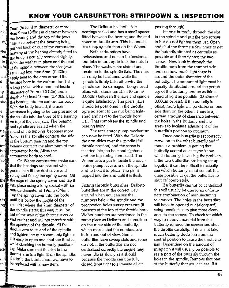
KNOW YOUR CARBURETTOR: STRIPDOWN & INSPECTION
7mm (5/16in) in diameter or more than 9mm in diameter between the bearing and the top of the jaws.
dy This is to prevent the bearing being pushed back or out of the carburettor housing as the bearing already fitted to the body is actually recessed slightly. With the washer in place and the end of the spindle between the vice jaws
nto to
.set at not less than 5mm (0.20in), . apply heat to the area around the
d bearing bore in the carburettor. Using a long socket with a nominal inside diameter of 7mm (0.312in) and a depth of at least lOmm (0.400in), tap the bearing into the carburettor body. With the body heated, the main resistance is going to be the pressing of the spindle into the bore of the bearing on top of the vice jaws. The bearing
·and spindle are seated when the
.y ot
ra
:k to:
to
the
is ing
f
ic
-
sound of the tapping becomes more 'solid' as the spindle contacts the side of the bottom bearing and the top bearing contacts the aluminum of the carburettor body. Allow the carblirettor body to cool.
On Weber carburettors make sure that the bearings are packed with grease then fit the dust cover and spring and finally the spring cover. Oil the edge of the spring cover and tap it into place using a long socket with an outside diameter of 19mm (3/4in). Tap the spring cover into the body until it is below the height of the shoulder where the 7mm diameter of the spindle siarts: this way it will be out of the way of the throttle lever or end washer and will not interfere with the opening of the throttle. Fit the throttle arm to its end of the spindle and tighten the nut reasonably tight so itis easy to open and shut the throttle while checking the butterfly position-ing. Make sure that the slot in the throttle arm is a tight fit on the spindle: if it isn't, the throttle arm will have to be replaced with a new item.
The Dellorto has both side bearings sealed and has a small spacer fitted between the bearing and the end cover or throttle arm. This is a much less fussy system than on the Weber.
Both carburettors have lockwashers and nuts to be tensioned and tabs to turn up to lock the nuts in place. The washers are slotted and locate on to the spindle flats. The nuts can only be tensioned while the spindle is firmly held otherwise the spindle can be damaged. Long-nosed pliers with aluminum shim (O.lmm/ 0.040in) between the jaws and spindle is quite satisfactory. The pliers' jaws should be positioned in the throttle bore adjacent to the nut being tight-ened and next to the throttle bore wall. That completes the spindle and bearing fitting.
The accelerator pump mechanism can now be fitted. With the Dellorto the arm slides over the spindle (full throttle position) and the screw is inserted into. the hole and tightened and the top spring connected. The Weber uses a pin to locate the accel-erator pump lever arm on the spindle and to hold it in place. The pin is tapped into the arm until it is flush.
Fitting throttle butterflies. Dellorto butterflies are in the correct way around when you can see the numbers below the spindle and the progression holes sweep recesses (if present) at the top of the throttle bore. Weber numbers are positioned in the same place as Dellorto and sometimes on the other side of the butterfly, which means that the numbers are inside and out of view. Some butterflies have sweep slots and some do not. If the butterflies are not centralized correctly the engine may never idle as slowly as it should because the throttle can't be fully closed (shut tight to eliminate all air
passing through). Fit one butterfly through the slot
in the spindle and put the two screws in but do not tighten them yet. Open and shut the throttle a few times to get the butterfly situated as centrally as possible and then tighten the two screws. Now look in through the throttle bore from the trumpet side and see how much light there is around the outer diameter of the butterfly. The amount of light must be equally distributed around the periph-ery of the butterfly and be as thin a band of light as possible (0.025mm/ O.OOlin or less). If the butterfly is offset, more light will be visible on one side than on the other. There is a certain amouni of clearance between the holes in the butterfly and the screws to facilitate adjustment of the butterfly's position to optimum.
Once one butterfly is set correctly move on to the other butterfly and if there is a problem in getting that butterfly central at least you know which butterfly is causing the problem. If the two butterflies are being set up together it can be difficult to actually see which butterfly is not central. It is quite possible to get the butterflies to shut off completely.
If a butterfly cannot be centralized this will usually be due to an unfortu-nate combination of manufacturing tolerances. The holes in the butterflies will have to opened out (elongated) using needle files to give more clear-ance to the screws. To check for which way to remove material from the butterfly remove the screws and shut the. throttle carefully. It does not take much butterfly deviation from the central position to cause the throttle to jam. Depending on the amount of mismatch it will usually be possible to see a part of the butterfly through the holes in the spindle. Remove that part of the butterfly that you can see. If it
35
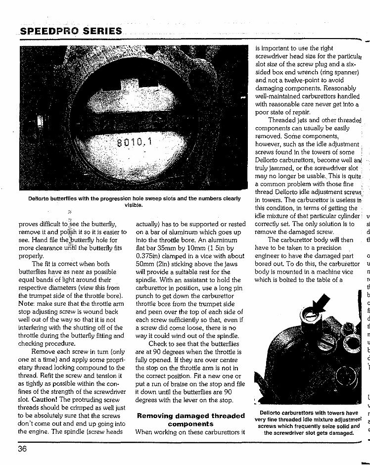
SPEEDPRO SERIES
Dellorto butterflies with the progression hole sweep slots and the numbers clearly visible.
proves difficult to see the butterfly, remove it and polishit so it is easier to see. Hand file the~butterfly hole for more clearance until the butterfly fits properly.
The fit is correct when both butterflies have as near as possible equal bands of light around their respective diameters (view this from the trumpet side of the throttle bore). Note: make sure that the throttle arm stop adjusting screw is wound back well out of the way so that it is not interfering with the shutting off of the throttle during the butterfly fitting and checking procedure.
Remove each screw in turn (only one at a time) and apply some propri-etary thread locking compound to the thread. Refit the screw and tension it as tightly as possible within the con-fines of the strength of the screwdriver slot. Caution! The protruding screw threads should be crimped as well just to be absolutely sure that the screws don't come out and end up going into the engine. The spindle (screw heads
36
actually) has to be supported or rested on a bar of aluminum which goes up into the throttle bore. An aluminum flat bar 3Smm by 1 Omm ( 1 Sin by 0.37Sin) clamped in a vice with about SOmm (2in) sticking above the jaws will provide a suitable rest for the spindle. With an assistant to hold the caiburettor in position, use a long pin punch to get down the carburettor throttle bore from the trumpet side and peen over the top of each side of each screw sufficiently so that, even if a screw did come loose, there is no way it could wind out of the spindle.
Check to see that the butterflies are at 90 degrees when the throttle is fully opened. If they are over centre the stop on the throttle arm is not in the correct position. Fit a new one or put a run of braise on the stop and file it down until the butterflies are 90 degrees with the lever on the stop.
Removing damaged threaded components
When working on these carburettors it
is important to use the right screwdriver head size for the particular slot size of the screw plug and a six-sided box end wrench (ring spanner) and not a twelve-point to avoid damaging components. Reasonably well-maintained carburettors handled with reasonable care never get into a poor state of repair.
Threaded jets and other threaded components can usually be easily removed. Some components, however, such as the idle adjustment . screws found in the towers of some Dellorto carburettors, become well and truly jammed, or the screwdriver slot may no longer be usable .. This is quite a common problem with those fine thread Dellorto idle adjustment screws· in towers. The carburettor is useless in this condition, in terms of getting the idle mixture of that particular cylinder correctly set. The only solution is to si remove the damaged screw. d
The carburettor body will then have to be taken to a precision engineer to have the damaged part o bored out. To do this, the carburettor u body is mounted in a machine vice rr which is bolted to the table of a
b
fi d tl n u b d '!
l
Dellorto carburettors with towers have n very fine threaded Idle mixture adjustment a
screws which frequentlyseize solid and e the screwdriver slot gets damaged.
-
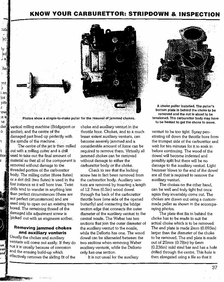
t
KNOW YOUR CARBURETTOR: STRIPDOWN & INSPECTION
Photos show a simple~to-make puller for the ~emoval of 'jammed choke·s.
vertical milling machine (Bridgeport or similar), and the centre of the damaged part lined up p'erfectly with the spindle of the machine.
The centre of the jetis then milled out with a milling cutter and a drill used to take out the final amount of material so that all of the component is removed without damage to the threaded portion of the carburettor body. The milling cutter (three flutes) or a slot drill (two flutes) is used in the first instance as it will bore true. Twist drills tend to wander in anything less than perfect circumstances (these are not perfect circumstances) and are used only to open out an existing true bored. The remaining thread of the damaged idle adjustment screw is 'picked' out with an engineers scriber.
Removing jammed chokes and auxiliary venturis
Usually the chokes and auxiliary venturis will come out easily. If they do not it is usually because of corrosion and the ensuing build-up which effectively removes the sliding fit of the
choke and auxiliary venturi in the throttle bore. Chokes, and to a much lesser extent auxiliary venturis, can become severely jammed and a considerable amountof forcecan be required to remove them. Virtually all jammed chokes can be removed without damage to either the carburettor body or the choke.
Check to see that the locking screw has in fact been removed from the carburettor body. Auxiliary ven-turis are removed by inserting a length of 12. 7mm (0.5in) wood dowel through the back of the carburettor throttle bore (one side of the opened butterfly) and contacting the bridge section edge that connects the outer diameter of the auxiliary venturi to the central nozzle. The Weber has two sections that join the outer diameter of the auxiliary venturi to the nozzle, while the Dellorto has one. The wood dowel can be alternated between the two sections when removing Weber auxiliary venturis, while the Dellorto only has one section.
It is not usual for the auxiliary
A choke puller installed. The puller's bottom plate is behind the 'choke to be
removed and the nut Is about to be tensioned. The carburettor body may have
to be heated to get the choke to move.
venturi to be too tight. Spray pen-etrating oil down the throttle bore from the trumpet side of the carburettor and wait for ten minutes for itto soak in before continuing. The wood of the dowel will become indented and possibly split but there will be no damage to the auxiliary venturi. Light hammer blows to the end of the dowel are all that is required to remove the auxiliary venturi.
The chokes on the other hand, can be well and truly tight but once again they invariably come out. The chokes are drawn out using a custom-made puller as shown in the accompa-nying photos.
The plate that fits in behind the choke has to be made to suit the actual choke which is to be removed. The end plate is made 2mm (0.093in) larger than the diameter of the choke to be removed. The end plate is made out of 20mm (0. 78in) by 6mm (0.236in) mild steel bar and has a hole drilled through the centre. This hole is then elongated using a file so that it
37

SPEEDPRO SERIES
becomes llmm (0.437in) long. The reason for the elongated hole or slot is to allow the end plate to be angled so that it can be inserted in through the choke. The outer edges of the end plate are chamfered to suit the taper of the choke so that both tapers fit each other as closely as possible. As a precaution against marking the inside of the choke with the bottom plate, place some. thin cardboard between the end plate and the choke's surfaces before the bottom plate is pulled up to contact the bore of the choke.
The main puller rod is 8mm(0.312in) diameter threaded bar stock and is cut to 110mm(4.25in) long. One end of the puller has a Nylock nut (a half nut or a cut down standard Nylock) and the other is just a plain hexagon nut.
The other parts of the puller are the same no matter what carburettor type or size is having a choke re-moved. The outer endplate is made of 20mm (0. 78in) wide by Smm (0.314in) thick mild steel flat bar and will have to be 55mm (2.16in) long and have a hole drilled through the middle with clearance on it to suit the diameter of the main puller rod.
The puller is inserted into the carburettor's throttle bore with the plate angled (as shown in the photo) and through the actual choke. The angled position of the plate allows the bottom plate to pass through the choke diameter and, when straight-ened, lock into the taper of the choke.
The top nut is wound down firmly on to the top plate (by hand) and then tensioned with a wrench (spanner), which will ultimately remove the choke. If the choke still refuses to move even with considerable tension on the nut, keep the tension on and heat the carburettor body (approxi-mately where the choke is) with a small propane gas torch. The body of
38
This emission controlled 40mm Weber carburettor has the idle mixture adjustment screw housed in a tower (A), an 'idle by-pass' screw plug -(B), recessed 'idle by-pass'
adjustment screw (C), accelerator pump top (d),and the progression holes' permanently pressed in brass plug (E).
the carburettor will absorb the heat and expand and, in so doing, momen-tarily become larger than the choke's outer diameter before the heat is transferred to the choke. Minor hot-to-the-touch heat only is applied to the carburettor body (excessive heat may distort it).
With the choke removed, clean the throttle bore using 280 or 320 grit wet and dry paper and kerosene (paraffin) until the surface inside is as near to polished as possible. The surface will not usually take a polish because it will be too stained. Clean the choke's and the auxiliary venturis'
outside diameter with wet and dry abrasive paper and the choke and auxiliary venturi will then be an easy fil into the throttle bores (the sliding fit or tolerance is approximately O.lmm/ 0.004in).
Recognising 40mm emission controlled sidedraught Weber
and Dellorto carburettors It's only the 40mm sidedraught Weber and Dellorto carburettors that have been subjected to the emission control modifications. It's quite vital that you can recognise these Weber and Dellorto carburettors because, while -
-
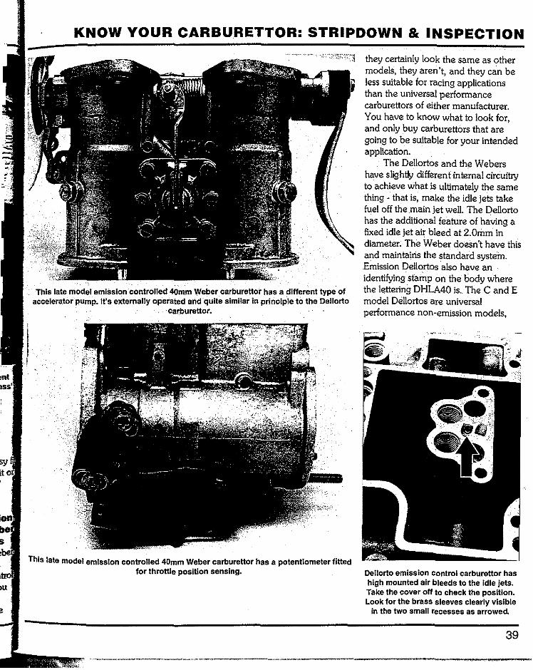
sy
KNOW YOUR CARBURETTOR: STRIPDOWN & INSPECTION
This late model emiSsion ·controlled 40mm Weber carburettor has a different type of accelerator· pump. It's externally operated and ·quite similar in principle to the Dellorto
carburettor.
This late model emission controlled 40mm Weber carburettor has a potentiometer fitted for throttle position sensing.
they certainly look the same as other models, they aren't, and they can be less suitable for racing applications than the universal performance carburettors of either manufacturer. You have to know what to look for, and only buy carburettors that are going to be suitable for your intended application.
The Dellortos and the Webers have slightly different internal circuitry to achieve what is ultimately the same thing - that is, make the idle jets take fuel off the main jet well. The Dellorto has the additional feature of having a fixed idle jet air bleed at 2.0mm in diameter. The Weber doesn't have this and maintains the standard system. Emission Dellortos also have an identifyingstamp on the body where the lettering DHLA40 is The C and E model Dellortos are universal performance non-emission models,
Oellorto emission control carburettor has high mounted air bleeds to the Idle jets. Take the cover off to check the position. Look for the brass sleeves clearly visible
in the two small recesses as arrowed
39
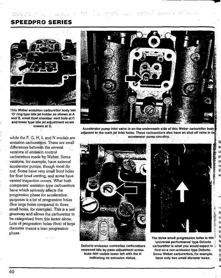
SPEEDPRO SERIES
This Weber emission carburettor body has '0' ring type Idle jet holder as .shown at A and 8, small float chamber vent hole at C and tower type Idle jet adjus_tment screw
towers at D.
while the F, G, H, L and N models are emission carburett6rs. There are small differences betweenthe several versions of emission control carburettors made by Weber. Some versions,ffor example,. have external accelerator pumps, though most do not Some have very small front holes for float bowl venting, and some have vented inspection covers. What both companies' emission type carburettors have which seriously affects the progression phase for acceleration purposes is a lot of progression holes (five large holes compared to three small holes, for example). This is a real giveaway and allows the carburettor to be categorised from this factor alone. Lots of progression holes (five) of large diameter means a lean progression phase.
40
Dellorto emission controlled carburettors recessed Idle by .. pass adjustment screw.
Note 40H visible lower leftwith the H indicating its emission status . .
w e<
Y< re th w
in The three small progression holes In this (t
'universal performance' type Dellorto carburettor is what you would expect to
find on a non-emlsslon type Dellorto. Some Weber carburettors, for example,
have only two small diameterholes.

·chapter 2 Rebuilding
all parts spotlessly clean and an equallyclean working area,the rebuild .
begin. Check the position of all against the exploded view of particular carburettor/s. The.
rebuild procedure that follows also lists the parts that need to be checked for
and possible replacement.
. Assemblystarts with the fittings of the and seat body into the ·
carburettor top.Put the aluminum washer overthe seat body and screw it
Using a six-sided box end wrench (ring spanner) tighten using reasonable tension. There is no need to go too tight as the thread is not large. Place the gasket on to the carburettor top as this must be in position before the floats are installed.
Dellorto needle and seat on the left (note the small filter.on the top of the seat), Weber needle and seat on the right.
FLOATS & FULCRUM PIN (DELLORTO)
Fulcrum pin checking Check the floats' fulcrum pin for wear grooves and, if there is any wear, replace it The pin, after some use, will have rub marks on its surface but this does not mean it is actually worn.
Unacceptable wear can be measured with a .vernier calliper ormicrometer. The pin first goes into the hole in the post without a slit as this is a clearance hole for the pin. The post with the slit is the one that applies tension to the pin by lightly clamping it when the pin is pressed into position. The post is able to expand slightly when the pin is pressed in because the slit allows movement
Floats checking If the carburettor is known to have done a lot of work, replace the floats. If they appear to be in serviceable condition place the pin in through the eyes and check to see how much .. movement there is between the pinand the eyes. Shake the float and listen for the sound of fuel sloshing around Inside it as this indicates a leak. Place the float in a bowl of fuel to check that it floats. Immerse the float in the fuel and check for air bubbles.
41
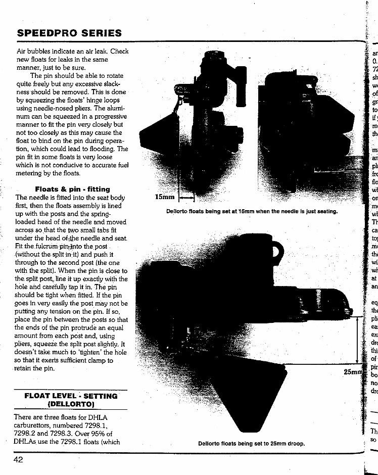
SPEEDPRO SERIES
Air bubbles indicate an air leak. Check new floats for leaks in the same manner, just to be sure.
The pin should be able to rotate quite freely but any excessive slack-ness should be removed. This is done by squeezing the floats' hinge loops using needle-nosed pliers. The alumi-num can be squeezed in a progressive manner to fit the pin very closely but not too closely as this may cause the float to bind on the pin during opera-tion, which could lead to flooding. The pin fit in some floats is very loose which is not conducive to accurate fuel metering by the floats.
Floats & pin fitting The needle is fitted into the seat body first, then the floats assembly is lined up with the posts and the spring-loaded head of the needle and moved across so .that the two small tabs fit under the head of theneedle and seat. Fit the fulcrum pin intothe post (without the split in it)and push it through to the second post (the one with the split). When the pin is close to the split post, line it up exactly with the hole and carefully tap it in. The pin should be tight when fitted. lfthe pin goes in very easily the post may not be putting any tension on the pin. If so, place the pin between the posts so that the ends of the pin protrude an equal amount from each post and, using pliers, squeeze the split post slightly. It doesn't take much to 'tighten' the hole so that it exerts sufficient clamp to retain the pin.
FLOAT LEVEL~ SETTING (DELLORTO)
There are three floats for DHLA carburettors, numbered 7298.1, 7298.2 and 7298.3. Over 95% of DHLAs use the 7298.1 floats (which
42
Dellorto floats being set at15mm when the needle Is justseating.
Dellorto floats being set to 25mm droop.
-sh
to
Th ca1
wil
at·
dr(
dr(
--
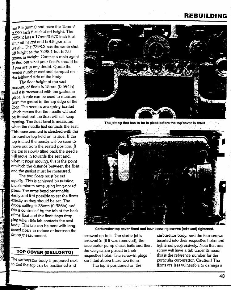
are 8.5 grams) and have the 15mm/ 0.590 inch fuel shut off height. The 7298.2 has a 17mm/0.670 inch fuel shut off height and is 8.5 grams in weight. The 7298.3 has the same shut off height as the 7298.1 but is 7. 0 grams in weight. Contact a main agent to find out what your float/s should be if you are in any doubt. Quote the model number cast and stamped on the lefthand side of the body.
The float height of the vast majority of floats is 15mm (0.594in) and it is measured with the gasket in place. A rule can be used to measure from the gasket to the top edge of the
The needles are spring-loaded which means that the needle will seal on its seat but the float will still keep noving The float level is measured
the needle just contacts the seat. This measurement is checked with the carburettor top held on its side. If the top is tilted the needle will be seen to move out from the seated position. If the top is slowly tilted back the needle will :move in towards the seat and, when it stops moving, this is the point at which the distance between· the float and the gasket must be measured.
The two floats must be set equally. This is achieved by twisting the aluminum arms using long-nosed pliers. The arms bend reasonably easily and it is possible to set the floats exactly as they should be set. The droop setting is 25mm (0. 985in) and this is controlled by the tab at the back of the float and the float stops drop-ping when this tab contacts the seat body. This tab can be bent with long-nosed pliers to reduce or increase the droop measurement.
TOP COVER (DELLORTO)
The carburettor body is prepared next so that the top can be positioned and
REBUILDING
The jetting that has to be In place before the top coverts fitted.
Carburettor top cover fitted and four securing screws (arrowed)tightened.
screwed on to it The starter jet is screwed in (if it was removed), the accelerator pump check balls and then the weights are placed in their respective holes. The screw-in plugs are fitted above these two items.
The top is positioned on the
carburettor body, and the four screws inserted into their respective holes and tightened progressively. Note that one screw will have a tab under its head; this.is the reference number for the particular carburettor. Caution! The floats are less vulnerable to damage if
43

SPEEDPRO SERIES
the cover carrying them is installed as soon as possible after setting the float height.
Caution! Make sure that all of the
44
screws used to secure the carburettor parts to the body have washers fitted between their heads and the body. This will prevent any damage to the
Dellortocarburettor top with the Inspection cover off showing the emulsion
tube holders and the Idle jet holders. i
Choke and auxiliary venturi positioned In front of a Oellorto carburettor. Fit the choke first, then the auxiliary venturi.
DellortO externally mounted idle mixtureadjustrtient.screw components (above)
and correctly assembled (below).
f
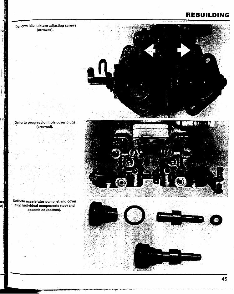
i.
oellorto Idle mixture adjusting screws (arrowed).
Dellorto progression hole cover plugs (arrowed).
Deliorto accelerator pump jet and cover plug Individual components (top) and
assembled (bottom).
REBUILDING
45

SPEEDPRO SERIES
Dellorto accelerator pump cover plugs (arrowed).
dellorto integ_ral f~el filter and fuel union components..
Choke location varies on some models Of Dellorto carburettors. This 48mm DHLA
uses screw location. Check to see that the hole In the choke is correctly lined up
before winding the screw In as, otherwise, the choke can get damaged!
aluminum of the castings.
BODY COMPONENTS
The main jet, emulsion tube and air corrector holder combination are assembled and inserted into their respective holes and tightened.
The idle jet and idle jet holder
Dellorto with plain throttle spindle cover (arrowed) correctly fitted. Note how tab
lockWasher Is turned up to lock the nut.
Dellorto. It's very Important that the throttle arm is a tight fit on the throttle spindle.
46
-
-

Oellorto throttle arm in position on the throttle spindle. Note raised tab to lock
nut.
Oellorto accelerator pump bottom well . Cf:?Ver fitted to actuating rod.
Dellorto accelerator pump bottom well cover fitted to carburet tor.
assembled and inserted into their respective holes, tightened and then the cover is placed over them and its two screws tightened.
The chokes first and then the auxiliary venturis are now inserted into the carburettofbody and the retaining screw turned in until it firmly contacts the auxiliary venturi. The nut is wound down till it contacts the carburettor body and tensioned using a six-point box end wrench (ringspanner). Reasonable·tension is applied to the nut while the screw is held with a screwdriver. This method of screw and nut locking only comes loose if the nut
REBUILDING is not secured correctly.
Screw in the idle mixture adjust-ing screws. Make sure that the spring, washer and the small rubber 0-rings are positioned in this order before screwing them in.
Screw in the progression hole plugs.
The accelerator pump jets are pressed into the screw plug and then inserted into their respective holes a~d tightened. Make sure that the small rubber 0-ring is fitted to the pump jet and that the fibre washer is fitted under the screw-in plug.
The fu~l union is fitted next. If the
47
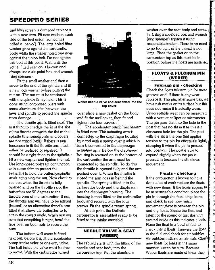
SPEEDPRO SERIES
fuel filter screen is damaged replace it with a new item. Fit new washers each side of the fuel union (sometimes caned a 'banjo'). The large holed fibre washer goes against the carburettor body while the· smaner holed one goes against the union bolt. Do not tighten this bolt at this point. Wait until the actual fitted position is known and always use a six-point box end wrench (ring spanner).
Fit the sman washer and then a cover to the end of the spindle and fit a new lock washer before putting the nut on. The nut must be tensioned with the spindle firmly held. This is done using long-nosed pliers with some aluminum shim between the jaws and spindle to protect the spindle from damage.
The throttle armis fitted next. The first thing to check isthe fit of the slot of the throttle arm,with the flat of the spindle (the round plainend covers are not critical here). If there is any looseness in fit the throttle arm must either be replaced or repaired. It should be a tight fit on to the spindle. Fit a new washer and tighten.the nut. Use long-nosed pliers (in conjunction with some shim to protect the butterfly) to hold the butterfly/spindle while tightening the nut. Now check to see that when the throttle is funy opened and on the throttle stop, the butterflies are 90 degrees to the throttle. bore of the. carburettor. If not, the throttle arm will have to be altered (brazed) or an alternative throttle arm fitted that allows the butterflies to to attain the correct angle. When you are sure that everything is right, bend the tabs over on both nuts to secure the nuts.
The bottom wen cover is fitted next but, before it is, fit the accelerator pump intake valve or one-way valve. The ban inside the valve must be free to move. With the carburettor turned
48
Weber needle valve and seat fitted Into the top cover.
over place a new gasket on the body and fit the wen cover, then fit and tighten the four screws.
The accelerator pump mechanism is fitted next. The actuating arm is connected to the diaphragm housing by a rod with a spring over it which in tum is connected to the diaphragm actuating arm. Before the diaphragm housing is screwed on to the bottom of the carburettor the arm must be connected to the spindle. To do this the throttle is opened funy and the arm pushed over it. When the throttle is closed the arm goes in behind the spindle. The spring is fitted into the carburettor body and the diaphragm into the diaphragm housing. The housing is then fitted to the carburettor body and secured with the four screws. Fit the spindle retuin spring.
At this point the Denorto carburettor is assembled ready to be fitted to the intake manifold.
NEEDLE VALVE & SEAT (WEBER)
The rebuild starts with the fitting of the needle and seat body into the carburettor top. Pui the aluminum
washer over the seat body and screw in. Using a six-sided box end wrench (ring spanner) tighten it using reasonable tension. There is no need to go too tight as the thread is not large. Place the gasket on to the carburettor top as this must be in position before the floats are instaned.
(
s
r
FLOATS & FULCRUM PIN (WEBER)·
Fulcrum pin • checking Check the floats fulcrum pin for wear grooves and, if there is any wear, replace it. The pin, after some use, will have rub marks on its surface but this does not mean it is actuany worn. Unacceptable wear can be measured with a vernier calliper or micrometer. The pin goes first into the hole in the post that has no slit in it as this is a clearance hole for the pin. The post with the slit is the one that applies tension.to the pin by effectively lightly clamping it when the pin is pressed into position. The post is able to expand slightly when the pin is pressed in because the slit anows movement
Floats checking If the carburettor is known to have done a lot of work replace the floats with new items. If the floats appear to be in serviceable condition place the pin in through the float hinge loops and check to see how much movement .there is between the pin and the floats. Shake the float and listen for the sound of fuel sloshing around inside as this indicates a leak. Place the float in a bowl of fuel to check that it floats. Immerse the float in the fuel and check for air bubbles. Air bubbles indicate an air leak. Check new floats for leaks in the same manner, just to be sure. Because Weber floats are made of brass they
1 b
c
h
s
v c
a p
c s
1 c n
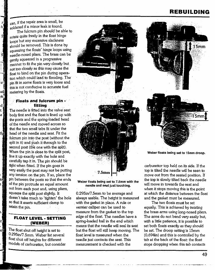
r. e
<.
can, if the repair area is small, be soldered if a minor leak is found.
The fulcrum pin should be able to rotate quite freely in the float hinge loops but any excessive slackness should be removed. This is done by squeezing the floats' hinge loops using needle-nosed pliers. The brass can be gently squeezed in a progressive manner to fit the pin very closely but not too closely as this may cause the float to bind on the pin during opera-tion which could lead to flooding. The pin fit in some floats is very loose and this is not conducive to accurate fuel metering by the floats.
Floats and fulcrum pin • fitting
The needle is fitted into the valve seat body first and the float is lined up with the posts and the spring-loaded head of the needle and moved across so that the two small tabs fit under the head of the needle and seat. Fit the fulcrum pin into the post (without the split in it) and push itthrough to the second post (the one with the split). When the pin is close to the split post, line it up exactly with the hole and carefully tap it in. The pin should be
. tight when fitted. If the pin goes in very easily the post may not be putting any tension on the pin. If so, place the pin between the posts so that the ends of the pin protrude an equal amount out from each post and, using pliers, squeeze the split post slightly. It doesn't take much to 'tighten' the hole so that it exerts sufficient clamp to retain the pin.
FLOAT LEVEL. SETTING (WEBER)
The float shut off height is set to 0.295in/7.5mm. Weber list several float shut off heights for different models of carburettor, but consider
Weber floats being set to 7.5mm with the needle and seat jusi touching.
0.295in/7.5mm to be average and always usable. The height is measured
. with the gasket in place. A rule or vernier calliper can be used to measure from the gasket to the top edge of the float The needles have a spring-loaded ball in the end which means that the needle will seal its seat but the float will still keep moving. The float level is measured when the needle just contacts the seat. This measurement is checked with the
REBUILDING
Weber floats being set to 15mm droop.
carburettor top held on its side. If the top is tilted the needle will be seen to move out from the seated position. If the top is slowly tilted back the needle will move in towards the·seat and when it stops moving this is the point at which the distance between the float and the gasket must be measured.
The two floats must be set equally. This is achieved by twisting the brass arms using long-nosed pliers. The arms do not bend very easily but, with a little. patience, it is possible to set both floats exactly as they should be set. The droop setting is 15mm (0.694in) and this is controlled by the tab at the back of the float: the float stops dropping when this tab contacts
49
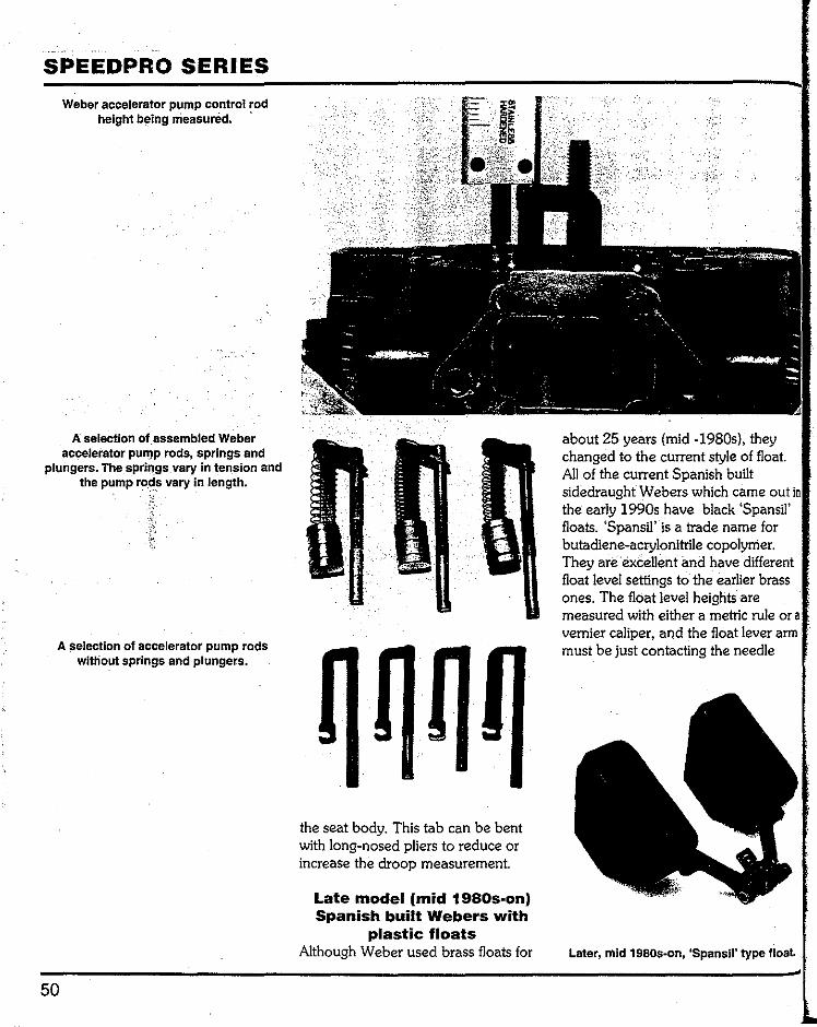
SPEEDPRO SERIES Weber ac:celerator pump control rod
height being rrieasured.
A selection of_assembled Weber accelerator pump rods, springs and
plungers. The sprin.gs _vary in tension and the pump rodsvary In length.
A selection of accelerator pump rods without springs and plungers.
50
the seat body. This tab can be bent with long-nosed pliers to reduce or increase the droop measurement.
Late model(mid 1980s-on) Spanish built Webers with
plastic floats Although Weber used brass floats for
about 25 years (mid -1980s), they changed to the current style of float. All of the current Spanish built sidedraught Webers which came out the early 1990s have black 'Spansil' floats. 'Spansil' is a trade name for butadiene-acrylonitrile copolymer. They are excellent and have different float level settings to the earlier brass ones. The float level heights are measured with either a metric rule or vernier caliper, and the float lever arm must be just contacting the needle
Later, mid 1980s-on,Spansiltype float.

Fuel shut off height (A) with the top cover gasket In place is 12.0mml0.4751nch (the
gasket Is not In place In the photo).
and seat. Weber also introduced a black
neoprene material carburettor body to top cover gasket. This material is less rigid, slightly thicker, and more able to guarantee a perfect seal.
The later Promek made Spanish built sidedraught Weber carburettors
Float 'lull droop' distance (B) Is 26mm-27mmJ1.025-1.0651nch In the position
shown with the top cover gasket In place (the gasket Is not In place In the photo).
Late type carburettor· body to top cover gasket.
(Promek took over frorri Magneti Marelli) are the only ones available today, and they are available in 40mm DCOE 151 and 45mm DCOE 152 versions with both having 'idle by-pass' circuitry and cast in towers on each side of the body to accommodate this system. They also have fuel enrichment mechanisms for cold starting purposes~ The Promek made Spanish built carburettors are also
REBUILDING
This Spanish built sidedraught SP Weber has 'Idle by-pass'circuitry. The
adjustment screw and lock nut is under the plastic cap arrowed.
available in 48mm, 50mm.and 55mm sizes as DCO/SP versions, with the SP standing for 'special' (racing purposes). None of these three DCO carburettors have 'idle by-pass' circuitry, and none of them have fuel
Spanish built 48mm DCO/SP sidedraught SP Weber with flat back.
51
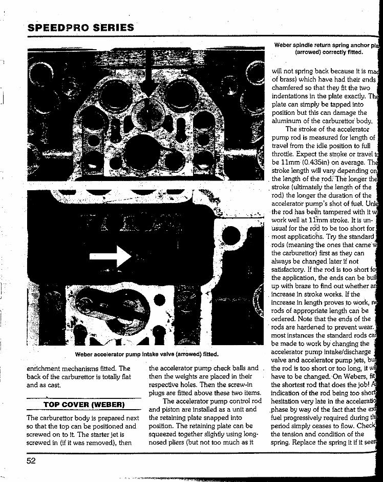
SPEEDPRO SERIES
Weber accelerator pump Intake valve (arrowed) fitted.
enrichment mechanisms fitted. The back of the carburettor is totally flat and as cast.
TOP COVER (WEBER)
The carburettor body is prepared next so that the top can be positioned and screwed on to it. The starter jet is screwed in (if it was removed), then
52
the accelerator pump check balls and then the weights are placed in their respective holes. Then the screw-in plugs are fitted above these two items.
The accelerator pump control rod and piston are installed as a unit and the retaining plate snapped into position. The retaining plate can be squeezed together slightly using long-nosed pliers (but not too much as it
Weber spindle return spring anchor (arrowed) correctly fitted.
will not spring back because it is of brass) which have had their ends chamfered so that they fit the two indentations in the plate exactly. plate can simply be tapped into position but this can damage the aluminum of the carburettor body.
The stroke of the accelerator pump rod is measured for length of travel from the idle position to full throttle. Expect the stroke or travel be llmm (0.435in) on average. stroke length will vary depending
. the length of the rod. Thelonger . stroke (ultimately the. length of the rod) the longer the duration of the accelerator pump's shot of fuel. the rod has beentampered with it work well at 1 imm stroke. It is un-usual for the rodto be too short for most applicatiohs. Try the stand<ud rods (meaning;the ones that came the carburettor) first as they can always be changed later if not satisfactory. If the rod is too short the application, the ends can be up with braze to find out whether increase in stroke works. If the increase in length proves to work, rods of appropriate length can be ordered. Note that the ends of the rods are hardened to prevent wear. most instances the standard rods be made to work by changing the accelerator pump intake/discharge valve and accelerator pump jets, the rod is too short or too long, it have to be changed. On Webers, the shortest rod that does the job! indication of the rod being too hesitation very late in the accelerati< .phase by way of the fact that the fuel progressively required during period simply ceases to flow. the tension and condition of the spring. Replace the spring it if it

Weber baffle plate (arrowed) shown fitted. All is now ready for fitting of the top
cover.
weak or is corroded. Fit the spindle return spring. The
eye of the spring is fitted to the accel-erator pump control lever first and the eye on the other end of the spring used to pull the spring up and through the hole where the anchoring plate is placed under the eye and the eye then let down into the register in the carburettor body. Care needs to be taken here when fitting the anchoring plate. The problem is one of holding the spring up high enough while fitting
anchoring plate. A small diameter shank screwdriver diameter) with a hook bent on to its end (heated up,· bent and then tem-pered back) is the solution and will prove to be fail-safe.
Fit the accelerator pump intake and discharge valve (if it has a hole drilled in the side of it) into the bottom of the fuel bowL: Do not over-tighten this valve as it can be very difficult to remove later. The slot size of the head is not very large and it is very easy to damage it.
Make sure the baffle plate fits into its recess in the carburettor body.
The top is positioned on to the carburettor body and the five screws inserted into their respective holes and tightened progressively. One screw will have a tab under its head; this is the reference number for the particular carburettor. Caution! The floats are less prone to damage if the cover Carrying them is installed as soon as Possible after setting float heights.
Caution! Make sure that all of the screws used to secure the carburettor Parts to the body have washers fitted between their heads and the body. This will prevent any marring of the aluminum of the castings.
REBUILDING
Weber top cover fitted. Arrows show securing screws.
BODY COMPONENTS (WEBER)
The main jet, emulsion tube, air corrector jet and emulsion tube holder combination are assembled and inserted into their respective holes and
tightened using a screwdriver with a head that fits the slots exactly to avoid any possibility of damage to the slots.
.The idle jet and idle jet holder are assembled and inserted into their respective holes and tightened then the jet inspection cover is placed over
53
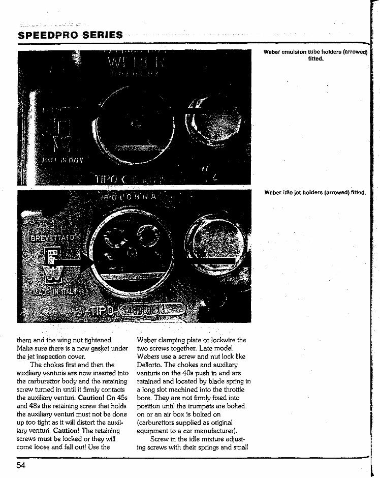
SPEEDPRO SERIES
them and the wing nut tightened. Make sure there is a new gasket under the jet inspection cover.
The chokes first and then the auxiliary venturis are now inserted into the carburettor body and the retaining screw turned in until it firmly contacts the auxiliary venturi. Caution! On 45s and 48s the retaining screw that holds the auxiliary venturi must not be done up too tight as it will distort the auxil-iary venturi. Caution! The retaining screws must be locked or they will come loose and fall out! Use the
54
Weber clamping plate or lockwire the two screws together. Late model Webers use a screw and nut lock like Dellorto. The chokes and auxiliary venturis on the 40s push in and are retained and located by blade spring in a long slot machined into the throttle bore. They are not firmly fixed into position until the trumpets are bolted on or an air box is bolted on (carburettors supplied as original equipment to a car manufacturer).
Screw in the idle mixture adjust-ing screws with their springs and small
Weber emulsion tube holders (arrowed) fitted.
Weber idle jet holders (arrowed) fitted.

Right- Weber choke and an auxiliary venturi shown positioned in front of the
carburetor before being installed.
Both 45mm and 48mm Webers use these set screws to secure their chokes and
auxiliary venturis. Lock wire each pair of set screws through the holes drilled into
them to prevent them coming out in service.
Weber idle miXture adJusting screws fitted.
washer fitted. Screw in the progression hole
plugs (new 0-ring fitted). The accelerator pump jets are
inserted into their respective holes with the small aluminum washers in place. The screw-in plug is then fitted with a new 0-ring seal fitted under the head of the plug.
The fuel union is fitted next. Fit new washers each side of the fuel union (sometimes called a 'banjo').
REBUILDING
The fibre washer with the small hole in it goes against the carburettor body while the fibre washer with the larger hole goes against the union bolt Do not tighten this bolt up at this point. Wait until the actual fitted position is known and always use a six-point box end wrench (ring spanner).
The filter inspection cover is fitted next. Fit a new filter element and a new fibre washer under the inspection plug. The fuel is under pressure and if
55
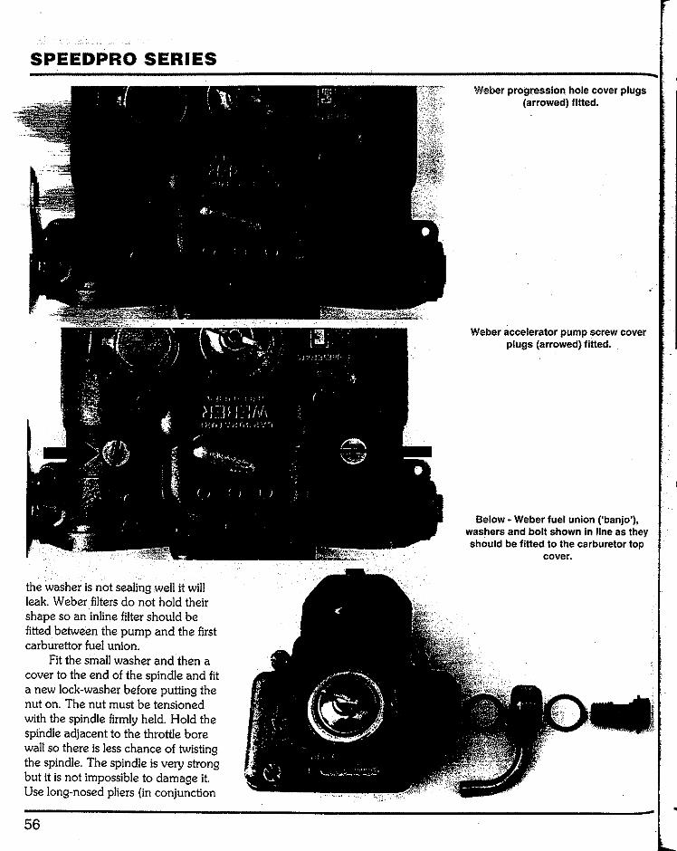
SPEEDPRO SERIES
the washeris not sealing well it will leak. Weber filters do not hold their shape so an inline filter should be fitted between the pump and the first carburettor fuel union.
Fit the small washer and then a cover to the end of the spindle and fit a new lock-washer before putting the nut on. The nut must be tensioned with the spindle firmly held. Hold the spindle adjacent to the throttie bore wall so there is less chance of twisting the spindle. The spindle is very strong but it is not impossible to damage it. Use long-nosed pliers (in conjunction
56
Weber progression hole cover plugs (arrowed) fitted.
Weber accelerator pump screw cover plugs (arrowed) fitted.
Below- Weber fuel union ('banjo'), washers and bolt shown in line as they should be fitted to the carburetor top
cover.
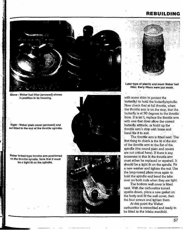
Above ·,Weber fuel filter (arrowed) shown in position in its housing.
Right· Weber plain cover (arrowed) and nut fitted to the end of the throttle spindle.
Weber linked-type throttle arm positioned on the throttle spindle. Note that it must
be a tight fit on the spindle.
REBUILDING
Later type of plastic and mesh Weber fuel filter. Early filters were just mesh.
with some shim to protect the butterfly) to hold the butterfly/spindle. Now check that at full throttle, when the throttle arm is on the stop, that the butterfly is at 90 degrees to the throttle bore. If is isn't, replace the throttle arm with one that does allow the correct butterfly attitude, or build up the throttle arm's stop with braze and hand file it to suit.
The throttle arm is fitted next· The first thing to check is the fit of the slot of the throttle arm to the flat of the spindle (the round plain end covers are not critical here). If there is any looseness in this fit the throttle arm must either be replaced or repaired. It should be a tight fit on the spindle. Fit a new washer and tighten the nut. Use the long-nosed pliers once again to hold the spindle and bend the tabs over on both nuts when they are tight.
The bottom well cover is fitted next. With the carburettor turned upside-down, place a new gasket on the body and fit the well cover, then the. four screws and tighten them.
At this point the Weber carburettor is assembled and ready to be fitted to the intake manifold.
57
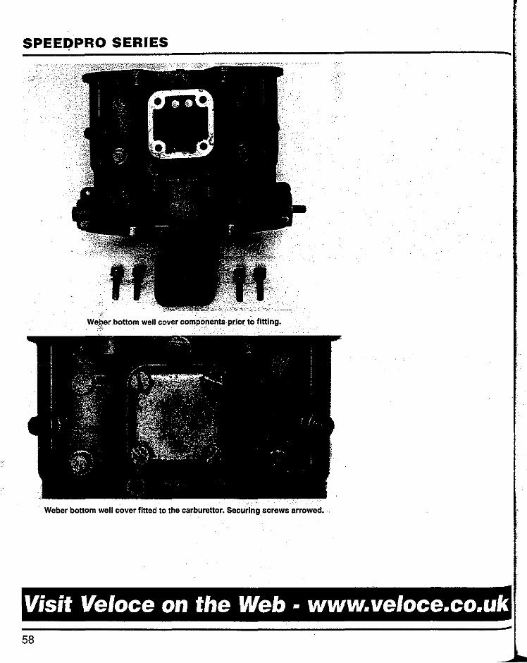
SPEEI;'PRO SERIES
We~er bottom well cover components prior to fitting •
Weber bottom well cover fitted to the carburettor. Securing. screws arrowed.
Visit Veloce on the Web· www.veloce.co.uk 58
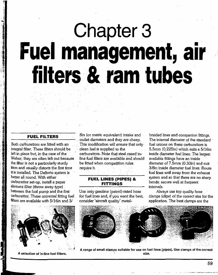
Chapter3 Fuel management, air
filters· & ram tubes
FUEL FILTERS
Both carburettors are fitted with an integral filier. These filters should be left in place but, in ihe case of the Weber, ihey are often left out because the filter is not a particularly sturdy item and usually distorts the first time it is installed. The Dellorto system is better all round. Wiih either carburettor set-up, install a paper element filter (throw away type) between the fuel pump and the first carburettor. These universal fitting fuel filters are available wiih 5/16in and 3/
A selection of In-line fuel filters.
8in(or metric equivalent) intake and outlet diameters and they are cheap. This modification will ensure that only clean fuel is supplied to the carburettors. Note ihat steel cased in-line fuel filters are available and should be fitted when competition rules require it.
FUEL LINES (PIPES) & FITTINGS
Use only gasoline (petrol)-rated hose for fuel lines and, if you want the best, consider 'aircraft quality' metal-
braided lines and companion fittings. The internal diameter of the standard fuel unions on ihese carburettors is S.Smin (0.225in) which suits a 5/16in inside diameter fuel lines. The largest available fittings have an inside diameter of 7.5mm (0.30in) and suit 3/Sin inside diameter fuel lines. Route fuel lines well away from the exhaust system and so that there are no sharp bends: secure well at frequent intervals.
Always use top quality hose clamps (clips) of the correct size for ihe application. The best clamps are the
A range of small clamps suitable for use on fuel lines (pipes). Use clamps of the correct size.
59
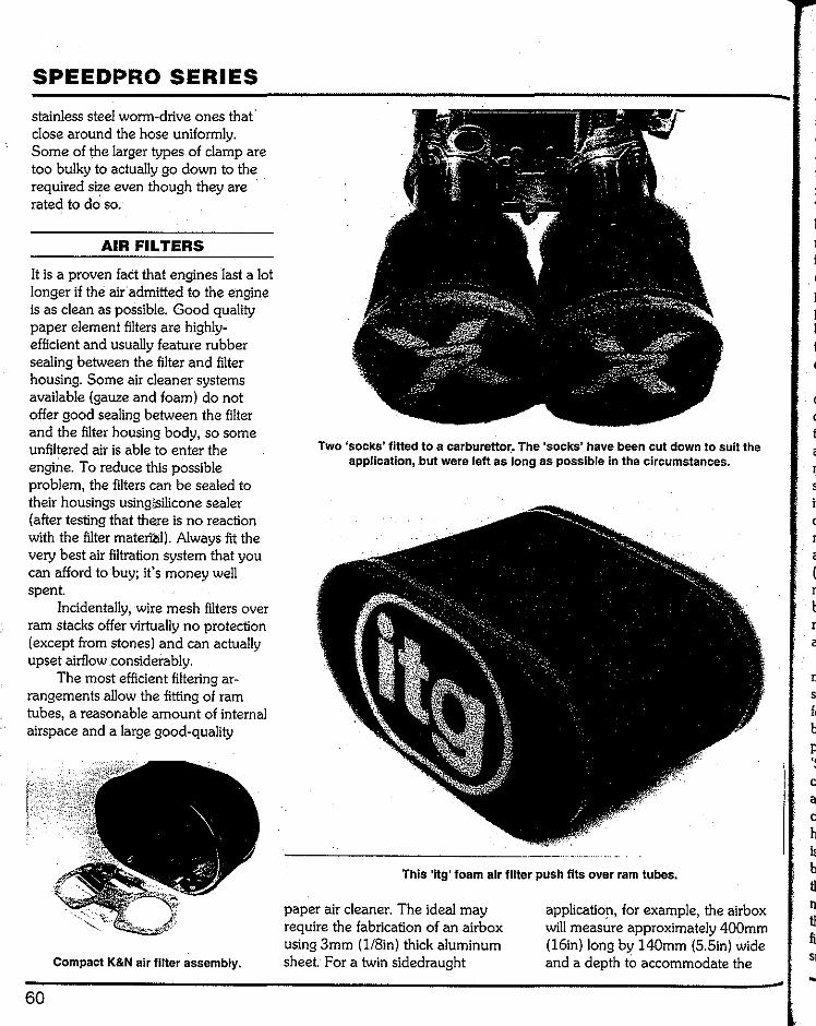
SPEEDPRO SERIES
stainless steel worm-drive ones thaf close around the hose uniformly. Some of the larger types of clamp are too bulky to actually go down to the required size even though they are rated to do so.
AIR FILTERS
It is a proven fact that engines last a lot longer if the air admitted to the engine is as clean as possible. Good quality paper element filters are highly-efficient and usually feature rubber sealing between the filter and filter housing. Some air cleaner systems available (gauze and foam) do not offer good sealing between the filter and the filter housing body, so some unfiltered air is able to enter the engine. To reduce this possible problem, the filters can be sealed to their housings using;silicone sealer (after testing that there is no reaction with the filter material). Always fit the very best air filtration system that you can afford to buy; it's money well spent.
Incidentally, wire mesh filters over ram stacks offer virtually no protection (except from stones) and can actually upset airflow considerably.
The most efficient filtering ar-rangements allow the fitting of ram tubes, a reasonable amount of internal airspace and a large good-quality
Compact K&N air filter assembly.
60
Two 'socks' fitted to a carburettor. The 'socks' have been cut down to suit the application, .but were left as long as possible in the circumstances.
This 'itg' foam air filter push fits over ram tubes.
paper air cleaner. The ideal may require the fabrication of an airbox using 3mm (1/8in)thick aluminum sheet. For a twin sidedraught
application, for example, the airbox will measure approximately 400mm (16in) long by 140mm (5.5in) wide and a depth to accommodate the
r s il (
r
a
n s f< b p '<
a c h is b tl rr tl fl 5( ..
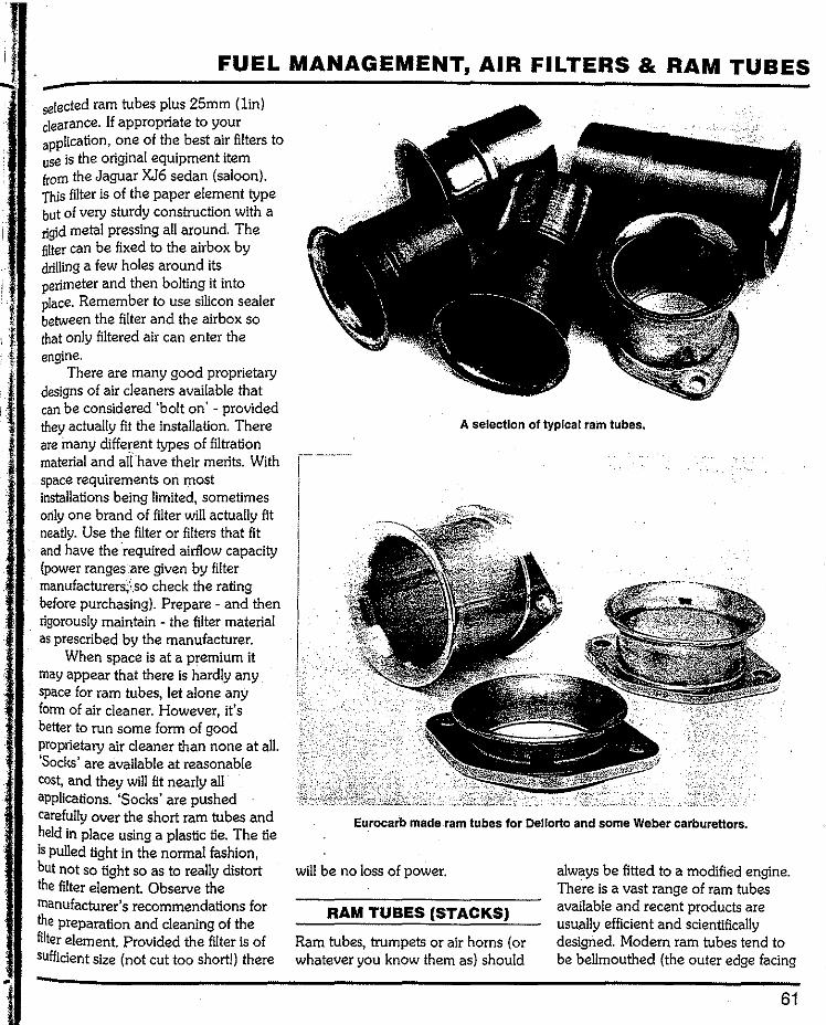
FUEL MANAGEMENT, AIR FILTERS & RAM TUBES
selected ram tubes plus 25mm (lin) clearance. If appropriate to your application, one of the best air filters to use is the original equipment item from the Jaguar XJ6 sedan (saloon). This filter is of the paper element type but of very sturdy construction with a rigid metal pressing all around. The filter can be fixed to the airbox by drilling a few holes around its perimeter and then bolting it into place. Remember to use silicon sealer between the filter and the airbox so that only filtered air can enter the engine.
There are many good proprietary designs of air cleaners available that can be considered 'bolt on' provided they actually fit the installation. There are inany different types of filtration material and a!rhave their merits. With space requirements on most installations being limited, sometimes only one brand of filter will actually fit neatly. Use the filter or filters that fit and have the ·required airflow capacity (power ranges are given by filter manufacturer~'.so check the rating before purchasing). Prepare- and then rigorously maintain the filter material as prescribed by the manufacturer.
When space is at a premium it may appear that there is hardly any space for ram tubes, let alone any form of air cleaner. However, it's better to run some form of good proprietary air cleaner than none at all. 'Socks' are available at reasonable cost, and they will fit nearly all applications. 'Socks' are pushed carefully over the short ram tubes and held in place using a plastic tie. The tie is pulled tight in the normal fashion, but not so tight so as to really distort the filter element. Observe the manufacturer's recommendations for the preparation and cleaning of the filter element. Provided the filter is of sufficient size (not cut too short!) there
A selection of typical ram tubes.
\
i.
EurOcarb made ram tubes for Dellorto and some Weber carburettors.
will be no loss of power.
RAM TUBES (STACKS)
Ram tubes, trumpets or air horns (or whatever you know them as) should
always be fitted to a modified engine. There is a vast range of ram tubes available and recent products are usually efficient and scientifically designed. Modern ram tubes tend to be bellmouthed (the outer edge facing
61
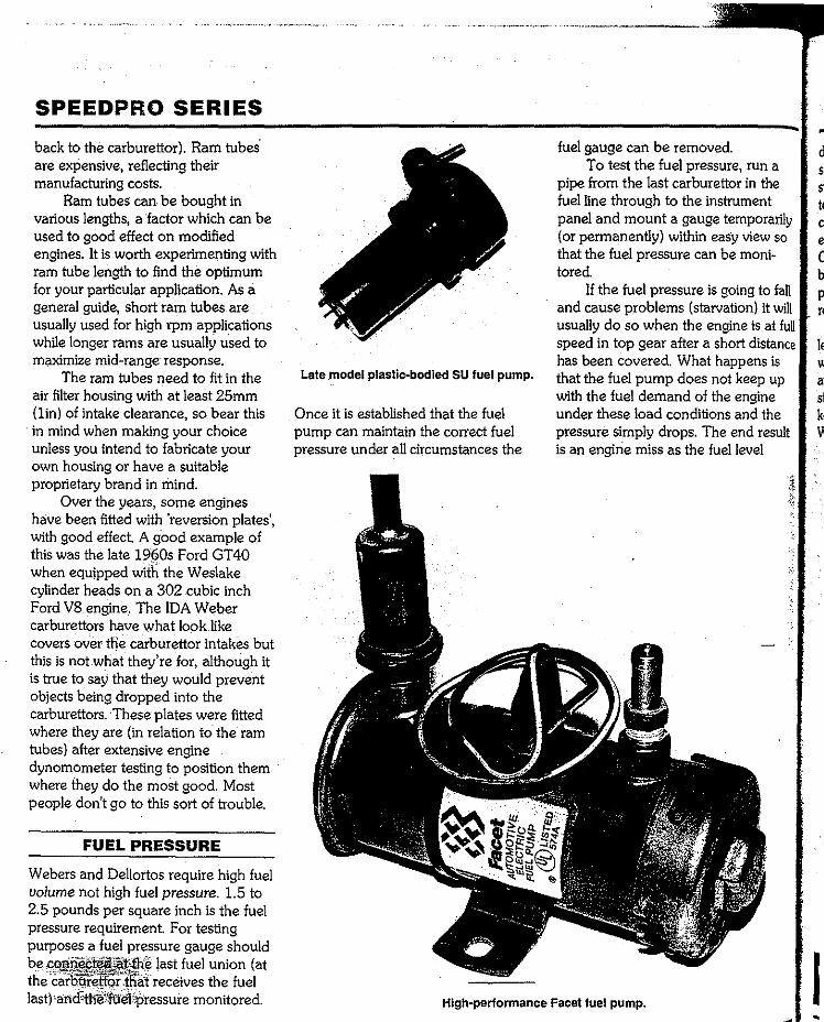
SPEEDPRO SERIES
back to the carburettor). Ram tubes' are expensive, reflecting their manufacturing costs.
Ram tubes can be bought in various lengths, a factor which can be used to good effect on modified engines. It is worth experimenting with ram tube length to find the optimum for your particular application. As a general guide, short ram tubes are usually used for high rpm applications while longer rams are usually used to maximize mid-range response.
The ram tubes need to fit in the air filter housing with at least 25mm (lin) of intake clearance, so bear this in mind when making your choice unless you intend to fabricate your own housing or have a suitable proprietary brand in mind.
Over the years, some engines have been fitted with 'reversion plates', with good effect. A goodexample of this was the late 1960sFord GT40 when equipped with the Weslake cylinder heads on a 302 cubic inch Ford V8 engine. The IDA Weber carburettors have what look like covers over the carburettor intakes but this is not what they're for, although it is true to say that they would prevent objects being dropped into the carburettors. These plates were fitted where they are (in relation to the ram tubes) after extensive engine dynamometer testing to position them where they do the most good. Most people don't go to this sort of trouble.
FUEL PRESSURE
Webers and Dellortos require high fuel volume not high fuel pressure. 1.5 to 2.5 pounds per square inch is the fuel pressure requirement. For testing purposes a fuel pressure gauge should be connected at the llast fuel union (at the barburettor thatreceives the fuel last) and the fuel pressuremonitored.
Late .model plastic-bodied SU fuel pump.
Once it is established that the fuel pump can maintain the correct fuel pressure under all circumstances the
fuel gauge can be removed. To test the fuel pressure, run a
pipe from the last carburettor in the fuel line through to the instrument panel and mount a gauge temporarily (or permanently) within easy view so that the fuel pressure can be moni-tored
If the fuel pressure is going to fall and cause problems (starvation) it will usually do so when the engine is at full speed in top gear after a short distance has been covered. What happens is that the fuel pump does not keep up with the fuel demand of the engine under these load conditions and the pressure simply drops. The end result is an engine miss as the fuel level
High-performance Facet fuel pump.
d
c b p
le
st ki
FUEL MANAGEMENT, AIR FILTERS & RAM TUBES
drops. If you have a gauge installed, as soon as the pressure goes you can stop. Do not proceed with high rpm testing until the correct fuel pressure can be maintained, otherwise the engine could be seriously damaged. Once the fuel pressure situation has been thoroughly checked out, the fuel pressure gauge and lines can be removed.
Achieving a fuel pressure of at least l.Spsi but not more than 2.5psi when the engine's fuel consumption is at its maximum is the aim. Many standard mechanical fuel pumps will keep up with the fuel requirements of Webers and Dellortos. If the fuel
delivery system is in first class order but still does not deliver enough fuel, you 'II need to consider fitting a me-chanical pump of higher capacity than the current item. It is also possible to bypass the standard mechanical pump and use instead a larger capacity electric pump to deliver the fuel.
If a single electric fuel pump is fitted as standard and a new one cannot supply sufficient fuel, consider fitting a second electric pump of the same type in parallel with the first. The second pump must have its own pick-up line (pipe) from the tank. The outlets of the two pumps can be merged into single fuel line with a
minimum inside diameter of 3/8in(or metric equivalent). The larger line can be reduced to 5/16in just before the fuel intake of the first (or only) carburettor so that the standard carburettor unions can be used.
Large capacity single electric pumps are available from several manufacturers (Holley and Facet for example) and these can pump at up to 1 Opsi and more, so they'll have to be used with a fuel pressure regulator. Too much pressure can overwhelm the needle valves and cause over-rich running.
Visit Veloce on the www.veloce.co.uk 63
Chapter 4 Choosing the
components for your carburettor/s
COMPONENTS • INITIAL SELECTION
The following tuning information is designed to assist you find a suitable start-up and run specification for your carburettor/s and your application. The set-up may not be perfect,but it will be quite sufficient to start with and can be improved upon by fine tuning.
Weber and Dellorto parts are high priced and usually quite a few of them are needed to fine tune an engine. Invariably parts are borrowed from other people to see if they work and then new or second-hand parts bought for final fitting to the engine. It can get very expensive having to buy jets just to try them out. Engine tuners usually (but not all) have the majority of parts in stock by way of a 'tuning kit'.
When tuning your own engine the cost of buying parts has to be bal-anced against the. actual cost of getting a specialist firrn to carry out this work. It is possible to spend a considerable
amount of money on jets, chokes, etc., (new or second-hand) that you will end up not using. Conversely, if the firm you are getting your engine tuned at does not have a comprehen-sive set of alternative parts the chances are they will not tune the engine correctly. They might get it going better than you think you can, but that doesn't mean that it's actually right.
CHOKE SIZE VERSUS CARBURETTOR SIZE
The information given here will allow you to sort out any sidedraught Weber or Dellorto on any suitable engine application. The first consideration before carburettors are purchased is to know what choke sizes are likely to be used. The reason for this is that carburettor bodies of a given size have a range of chokes that will fit them. The correct range of choke sizes for both Weber and Dellorto carburettors is as follows.
40mm diameter carburettors: choke range 28mm-34mm
45mm diameter carburettors: choke range 36mm to 41mm
48mm diameter carburettors: choke range 41mm to 43mm
There is some overlap of possible choke sizes on these carburettors. A 34mm choke is definitely the maxi-mum size to use in a 40 DCOE or 40 DHLA body. 36mm chokes are available from Weber and Dellorto for fitting into their 40s but the flow capacity is definitely not as good as a 36mm choke in a 45 body. The 45s can have 34mm chokes fitted which, while within the sizing tolerance of a 40 body, still work well in a 45. The 48s could have 34mm chokes fitted (in the range of 40 bodies) or 36mm, 38mm and 40mm chokes fitted (in the range of 45 bodies) and also work well.
Choke size is the major consider-ation. Very small choke sizes in large
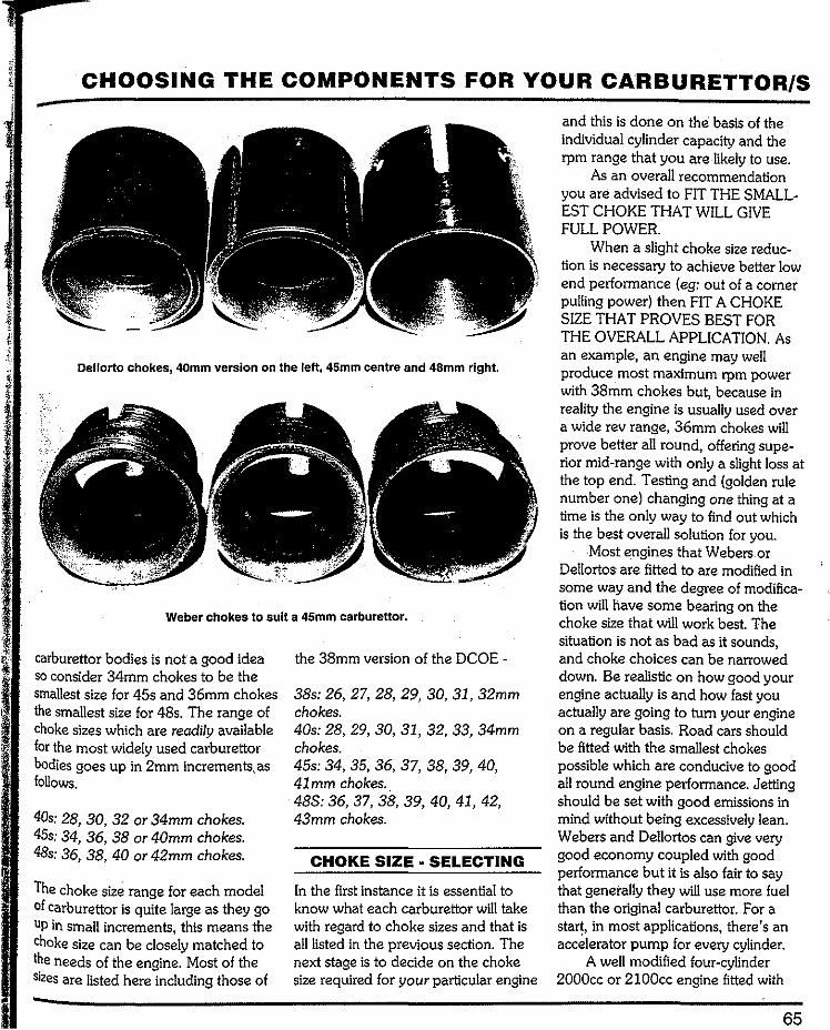
CHOOSING THE COMPONENTS FOR YOUR CARBURETTOR/S
Oellorto chokes, 40mm version on the left, 45mm centre and 48mm right.
Weber chokes to suit a 45mm carburettor.
carburettor bodies is not a good idea so consider 34mm chokes to be the smallest size for 45s and 36mm chokes the smallest size for 48s. The range of choke sizes which are readily available for the most widely used carburettor bodies goes up in 2mm increments, as follows.
40s: 28, 30, 32 or 34mm chokes. 45s: 34, 36, 38 or 40mm chokes. 48s: 36, 38, 40 or 42mm chokes.
The choke size range for each model of carburettor is quite large as they go Up in small increments, this means the choke size can be closely matched to the needs of the engine. Most of the sizes are listed here including those of
the 38mm version of the DCOE -
38s: 26, 27, 28, 29, 30, 31, 32mm chokes. 40s: 28, 29, 30, 31, 32, 33, 34mm chokes. 45s: 34, 35, 36, 37, 38, 39, 40, 41mm chokes .. 48S: 36, 37, 38, 39, 40, 41, 42, 43mm chokes.
CHOKE SIZE • SELECTING
In the first instance it is essential to know what each carburettor will take with regard to choke sizes and that is all listed in the previous section. The next stage is to decide on the choke size required for your particular engine
and this is done on the basis of the individual cylinder capacity and the rpm range that you are likely to use.
As an overall recommendation you are advised to FIT THE SMALL-EST CHOKE THAT WILL GIVE FULL POWER.
When a slight choke size reduc-tion is necessary to achieve better low end performance (eg: out of a corner pulling power) then FIT A CHOKE SIZE THAT PROVES BEST FOR THE OVERALL APPLICATION. As an example, an engine may well produce most maximum rpm power with 38mm chokes but, because in reality the engine is usually used over a wide rev range, 36mm chokes will prove better all round, offering supe-rior mid-range with only a slight loss at the top end. Testing and (golden rule number one) changing one thing at a time is the only way to find out which is the best overall solution for you.
Most engines that Webers or Dellortos are fitted to are modified in some way and the degree of modifica-tion will have some bearing on the choke size that will work best. The situation is not as bad as it sounds, and choke choices can be narrowed down. Be realistic on how good your engine actually is and how fast you actually are going to tum your engine on a regular basis. Road cars should be fitted with the smallest chokes possible which are conducive to good all round engine performance. Jetting should be set with good emissions in mind without being excessively lean. Webers and Dellortos can give very good economy coupled with good performance but it is also fair to say that generally they will use more fuel than the original carburettor. For a start, in most applications, there's an accelerator pump for every cylinder.
A well modified four-cylinder 2000cc or 2100cc engine fitted with
65

SPEEDPRO SERIES
twin sidedraughts will usually run best using 38mm chokes with 40mm chokes being too large. On the other side of the scale, if mid-range perfor-mance is preferred to absolute top end power 36mm diamete.r chokes will prove to be a better choice. The readily available range of choke sizes increases in 2mm increments and is nearly always satisfactory for achieving the 'right' size.
It is reasonably easy to establish the range of choke sizes and then know what carburettor you will require. If the engine needs 36mm or 38mm chokes then 45 carburettors are the size to buy. If the engine needs 34mm chokes then 40 carburettors are usuaJ!y the size to buy but this choke size is at the limit of the 40 carburettor body. The latter is a good example of the choice of carburettor body versus the true requirements with regard to choke size. In most instances, unless your engine reaslly isa heavily modi-fied unit, the 40s with 34mm chokes will prove to be the best choice, especially for a street car.
The following recommended choke sizes are for engines that are modified and have an effective rev range from approximately· 3000rpm to 8000rpm for the smaller engines (lOOOcc to 1750cc) and 2500rpm to 7500rpm for intermediate engines (1750cc to 2400cc) and around 2000rpm to 6500rpm for larger units.
Many engines are bored out beyond standard capacities; however, when consulting the following choke size tables, use the actual capacity of your engine.
For your convenience the follow-ing choke sizes are listed in relation to ccs per cylinder so that the sizes can be cross referenced to any engine. If your engine is an in-between capacity go to the next choke size down. Always be prepared to go to a smaller
choke size if tuning proves difficult. The common choke sizes listed below· are basic starting points.
Choke sizes(on basis of one choke per cylinder)-
28mm chokes: 250cc per cylinder. 30mm chokes: 300cc per cylinder. 32mm cho_kes: 350cc per cylinder. 34mm chokes: 400cc per cylinder. 36mm chokes: 462cc per cylinder. 38mm chokes: 525cc per cylinder. 40mm chokes: 600cc per cylinder. 43mm chokes: BOOcc per cylinder.
The even sized choke numbers (32, 34, 36 and so on) are far more common and easily obtained than the odd sized choke numbers (31, 33, 35 and so on) and, as a consequence, engines are generally fitted with the most suitable even numbered sized choke. A 1300cc engine can have 30mm choke fitted initially but the engine may prove to need 32mm (or even 31mm) chokes after testing. The chart above is close enough for initial setting and the 2mm increments in choke sizing not usually too large as steps up or down during fine tuning. There is a degree of latitude with choke sizes but one choke size will always work better than all of the others for a particular application.
In the first instance use the even numbered chokes simply because of their easy availability but be aware of the fact that in-between sizes do exist and an odd sized choke may ulti-mately prove to be the correct one for your engine.
Intermediate choke sizes (on basis of one choke per cylinder) -
29mm chokes: 278cc per cylinder. 31 mm chokes: 325cc per cylinder. 33mm chokes: 375cc per cylinder.
35mm chokes: 425cc per cylinder. 37mm chokes: 475cc per cylinder. 39mm chokes: 565cc per cylinder
The list which follows is in addi-tion to the above and for large capac-ity engines. Choke sizes for large engines (on of one choke per cylinder) -
40mm chokes in 45s or 48s: 600cc per cylinder.
41 mm chokes in 45s or 48s: 700cc per cylinder.
42mm chokes in 48s: BOOcc per cylinder.
43mm chokes in 48s: 900cc per cylinder.
There is another scenario that can be applied to all engines that are modified for occasional competition yet must be used most of the time as daily transport. That is to have two sets of chokes and jets: one set for each situation. If, for instance, a 2000cc four-cylinder engine with one choke per cylinder needs 38mm chokes with suitable jetting for compe-tition use to obtain a maximum usablerpm of 7800, there's no reason why these. chokes cannot be changed later to 34mm with suitable jetting. The low end performance of the engine will actually be improved and all you will notice at the top end is a very sudden and definite flattening off at a certain rpm, beyond which the engine simply will not go. With smaller chokes fitted the jetting can be reduced without detriment. What you will have done is governed the maximum engine speed by restricting the air supply. With 34mm chokes fitted, a good 2000cc engine will usually still go well up to 6000rpm or so.
Some engines, notably the BMC/ Rover A-series and B-series four-cylinder engines, are Siamese intake
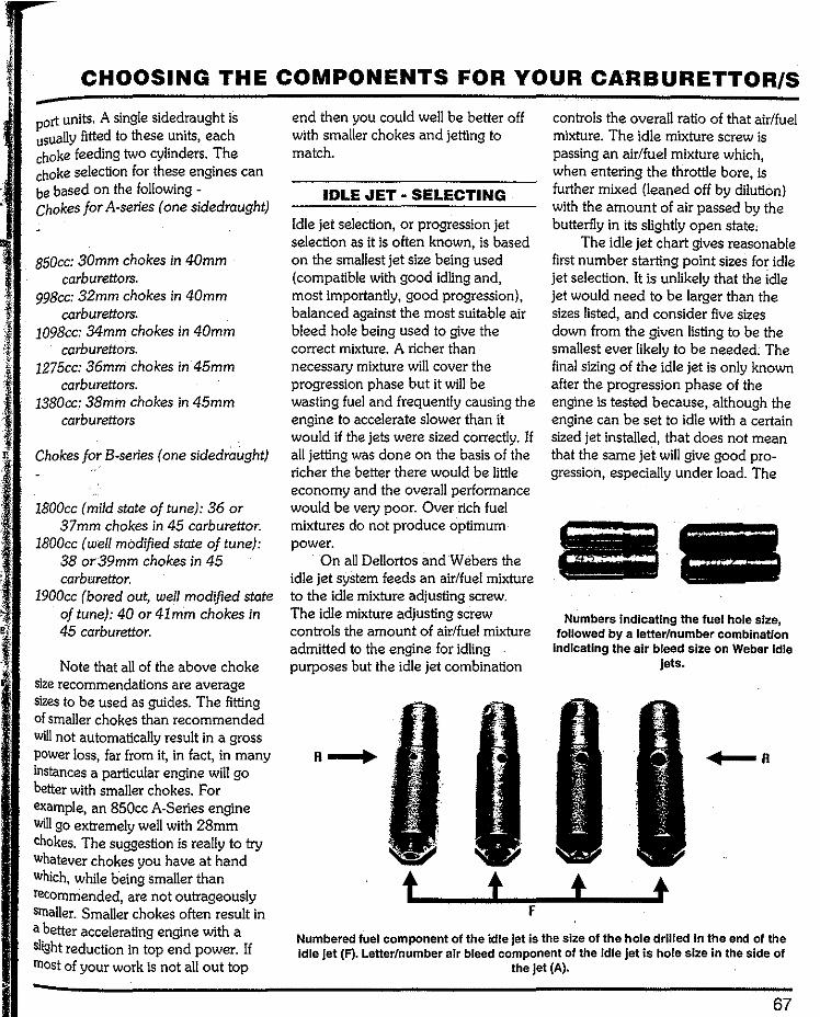
CHOOSING THE COMPONENTS FOR YOUR CARBURETTOR/S
port units. A single sidedraught is usually fitted to these units, each choke feeding two cylinders. The choke selection for these engines can be based on the following -Chokes for A-series (one sidedraught)
B50cc: 30mm chokes in 40mm carburettors.
998cc: 32mm chokes in 40mm carburettors.
1098cc: 34mm chokes in 40mm carburettors.
1275cc: 36mm chokes in 45mm carburettors.
1380oc: 38mm chokes in 45mm carburettors
Chokes forB-series (one sidedraught)
lBOOcc (mild state of tune): 36 or 37mm chokes in 45 carburettor.
lBOOcc (well modified state of tune): 38 or:39mm chokes in 45 carburettor.
1900cc (bored out, well modified state of tune): 40 or 4lmm chokes in 45 carburettor.
Note that all of the above choke size recommendations are average sizes to be used as guides. The fitting of smaller chokes than recommended will not automatically result in a gross power loss, far from it, in fact, in many instances a particular engine will go better with smaller chokes. For example, an 850cc A-Series engine Will go extremely well with 28mm chokes. The suggestion is really to try whatever chokes you have at hand Which, while being smaller than recommended, are not outrageously smaller. Smaller chokes often result in a better accelerating engine with a slight reduction in top end power. If most of your work is not all out top
end then you could well be better off with smaller chokes and jetting to match.
IDLE JET • SELECTING
Idle jet selection, or progression jet selection as it is often known, is based on the smallest jet size being used (compatible with good idling and, most importantly, good progression), balanced against the most suitable air bleed hole being used to give the correct mixture. A richer than necessary mixture will cover the progression phase but it will be wasting fuel and frequently causing the engine to accelerate slower than it would if the jets were sized correctly. If all jetting was done on the basis of the richer the better there would be little economy and the overall performance would be very poor. Over rich fuel mixtures do not produce optimum power.
On all Dellortos and Webers the idle jet system feeds an air/fuel mixture to the idle mixture adjusting screw. The idle mixture adjusting screw controls the amount of air/fuel mixture admitted to the engine for idling purposes but the idle jet combination
t t F
controls the overall ratio of that air/fuel mixture. The idle mixture screw is passing an air/fuel mixture which, when entering the throttle bore, is further mixed (leaned off by dilution) with the amount of air passed by the butterfly in its slightly open state,
The idle jet chart gives reasonable first number starting point sizes for idle jet selection. It is unlikely that the idle jet would need to be larger than the sizes listed, and consider five sizes down from the given listing to be the smallest ever likely to be needed. The final sizing of the idle jet is only known after the progression phase of the engine is tested because, although the engine can be set to idle with a certain sized jet installed, that does not mean that the same jet will give good pro-gression, especially under load. The
----- ---Numbers indicating the fuel hole size,
followed by a letter/number combination Indicating the air bleed size on Weber Idle
jets.
t Numbered fuel component of the idle jet Is the size of the hole drilled In the end of the Idle jet (F). Letter/number air bleed component of the Idle jet is hole size In the side of
the jet (A).
67
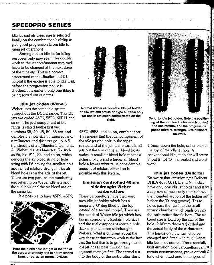
SPEEDPRO SERIES
idle jet and air bleed size is selected finally on the combination's ability to give good progression (from idle to main jet operation).
Sorting out an idle jet for idling purposes only may seem like double work as the jet combination may well have to be changed at the next stage of the tune-up. This is a correct assessment of the situation but it is helpful if the engine is able to idle well, before the progression phase is checked. It is easier if only one thing is being sorted out at a time.
Idle jet codes (Weber) Weber uses the same idle system throughout the DCOE range. The idle jets are coded 45F6, 55F2, 60Fll and so on. The fuel component of the range is stated bythe first two numbers 35, 40, 45, 50, 55 etc. and denotes the hole .size in hundredths of a millimeter and ~e sizes go up in 5 hundredths of a millimeterincrements. All Weber idle jetS have a suffix such as F6, F9, Fll, F2, and so on, which denotes the air bleed sizing or hole sizing with F6 having the smallest hole and richest mixture strength. The air bleed hole is on the side of the jet. There are two parts to the numbering and lettering on Weber idle jets and the fuel hole and the air bleed are on the same jet.
It is possible to have 45F9, 45F6,
Here the bleed hole Is right at the top of the .carburettor body and is not recessed
Smm, or so, as on normal DHLAs.
Normal Weber carburettor Idle jet holder on the left and emission type suitable only
for use In emission carburettors on the right.
45F2, 45F8, and so on, combinations. This means that the fuel component of the idle jet (the hole in the taper seated end of the jet) is the same in all jets butthe size of the air bleed holes varies. A small air bleed hole means a richer mixture and a larger air bleed hole a leaner mixture. A considerable amount of mixture alteration is possible with this system.
Emission controlled 40mm sidedraught Weber
carburettors These carburettors have their very own idle jet holder which has a neoprene '0' ring fitted at the top instead of a second thread. They use the standard Weber idle jet which has the air component (certain hole size) and the fuel component (certain hole size) as per all other sidedraught Webers. What is different about the way these carburettors work is the fact that the fuel that is to go through each idle jet has to pass through the adjacent main jet first. The thread cut into the body of the carburettor starts
Dellorto idle jet holder. Note the position. ing of the air bleed holes which control
the idle mixture and the progression phase mixture strength. Size numbers
arrowed.
7. 5mm down the hole, rather than at the top of the idle jet hole. A conventional idle jet holder will screw in but is not '0' ring sealed and won't work.
Idle jet codes (Dellorto) Be aware that emission type Dellorto DHLA 40F, G, H, L and N models have only one idle jet holder and it has a top row of holes only (that's above the threaded section of the holder and before the '0' ring groove). These holes pass the fuel into the small mixing chamber which leads on into the carburettor throttle bore. The air bleed size is fixed by the size of the hole (2.00mm diameter) drilled into the actual body of the carburettor. This leaves only the fuel jet to be changed and fitted with much larger idle jets than normal. These specially built emission type carburettors can, in certain circumstances, prove difficult to tune when fitted onto other types of
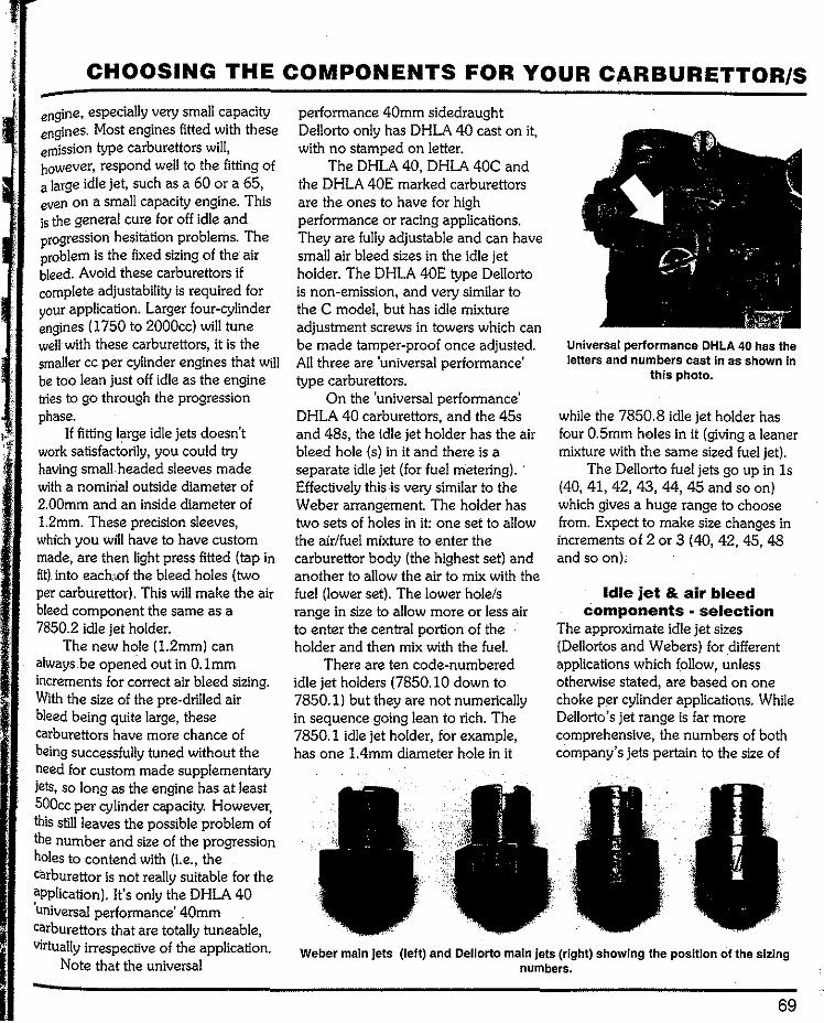
CHOOSING THE COMPONENTS FOR YOUR CARBURETTOR/S
engine, especially very small capacity engines. Most engines fitted with these emission type carburettors will, however, respond well to the fitting of a large idle jet, such as a 60 or a 65, even on a small capacity engine. This is the general cure for off idle and progression hesitation problems. The problem is the fixed sizing of the air bleed. Avoid these carburettors if complete adjustability is required for your application. Larger four-cylinder engines (1750 to 2000cc) will tune well with these carburettors, it is the smaller cc per cylinder engines that will be too lean just off idle as the engine tries to go through the progression phase.
If fitting large idle jets doesn't work satisfactorily, you could try having small.headed sleeves made with a nominal outside diameter of 2. 00mm and .an inside diameter of 1.2mm. These precision sleeves, which you wfil have to have custom made, are then light press fitted (tap in fit) into each-,of the bleed holes (two per carburettor). This will make the air bleed component the same as a 7850.2 idle jet holder.
The new hole (1.2mm) can always be opened out in 0.1mm increments for correct air bleed sizing. With the size of the pre-drilled air bleed being quite large, these carburettors have more chance of being successfully tuned without the need for custom made supplementary Jets, so long as the engine has at least SOOcc per cylinder capacity. However, this still leaves the possible problem of the number and size of the progression holes to contend with (i.e., the carburettor is not really suitable for the application). It's only the DHLA 40 'universal performance' 40mm carburettors that are totally tuneable, Virtually irrespective of the application.
Note that the universal
performance 40mm sidedraught Dellorto only has DHLA 40 cast on it, with no stamped on letter.
The DHLA 40, DHLA 40C and the DHLA 40E marked carburettors are the ones to have for high performance or racing applications. They are fully adjustable and can have small air bleed sizes in the idle jet holder. The DHLA 40E type Dellorto is non-emission, and very similar to the C model, but has idle mixture adjustment screws in towers which can be made tamper-proof once adjusted. All three are 'universal performance' type carburettors.
On the 'universal performance' DHLA 40 carburettors, and the 45s and 48s, the idle jet holder has the air bleed hole (s) in it and there is a separate idle jet (for fuel metering). Effectively this is very similar to the Weber arrangement. The holder has two sets of holes in it: one set to allow the air/fuel mixture to enter the carburettor body (the highest set) and another to allow the air to mix with the fuel (lower set). The lower hole/s range in size to allow more or less air to enter the central portion of the holder and then mix with the fuel.
There are ten code-numbered idle jet holders (7850.10 down to 7850.1) but they are not numerically in sequence going lean to rich. The 7850.1 idle jet holder, for example, has one 1.4mm diameter hole in it
Universal performance DHLA 40 has the letters and numbers cast In as shown In
this photo.
while the 7850.8 idle jet holder has four 0.5mm holes in it (giving a leaner mixture with the same sized fuel jet).
The Dellorto fuel jets go up in 1s (40, 41, 42, 43, 44, 45 and so on) which gives a huge range to choose from. Expect to make size changes in increments of 2 or 3 ( 40, 42, 45, 48 and so on),
Idle jet & air bleed components selection
The approximate idle jet sizes (Dellortos and Webers) for different applications which follow, unless otherwise stated, are based on one choke per cylinder applications. While Dellorto's jet range is far more comprehensive, the numbers of both company's jets pertain to the size of
Weber main jets (left) and Dellorto main Jets (right) showing the position of the sizing numbers.
69
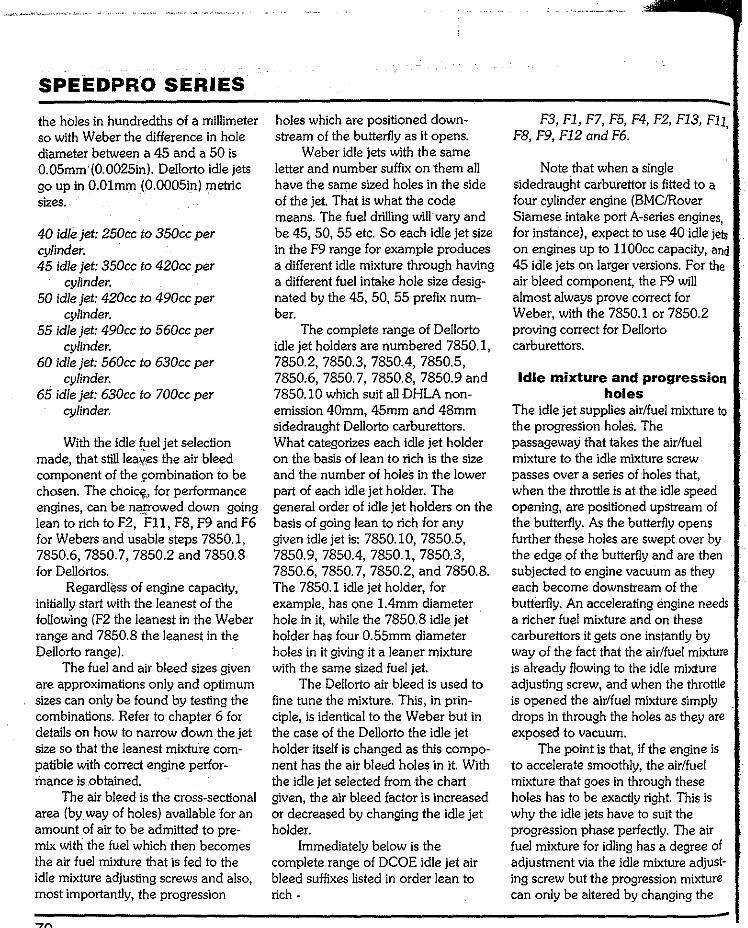
SPEEDPRO SERIES
the holes in hundredths of a millimeter so with Weber the difference in hole diameter between a 45 and a 50 is 0.05mm·(0.0025in). Dellorto idle jets go up in O.Olmm (0.0005in) metric sizes.
40 idle jet: 250cc to 350cc per cylinder. 45 idle jet: 350cc to 420cc per
cylinder. 50 idle jet: 420cc to 490cc per
cylinder. 55 idle jet: 490cc to 560cc per
cylinder. 60 idle jet: 560cc to 630cc per
cylinder. 65 idle jet: 630cc to 700cc per
cylinder.
With the idle fuel jjet selection made, that still leaves the air bleed component of the combonationto be chosen. The choice,for performance engines, can be narroweddown going lean to rich to F2, Fll, F8, F9 and F6 for Webers and usable steps 7850.1, 7850.6, 7850.7,7850.2 and 7850.8 for Dellortos.
Regardless of engine capacity, initially start with the leanest of the following (F2 the leanest in the Weber range and 7850.8 the leanest in the Dellorto range).
The fuel and air bleed sizes given are approximations only and optimum sizes can only be found by testing the combinations. Refer to chapter 6 for details on how to narrow down the jet size so that the leanest mixture com-patible with correct engine perfor-mance is .obtained.
The air bleed is the cross-sectional area (by way of holes) available for an amount of air to be admitted to pre-mix with the fuel which then becomes the air fuel mixiure that is fed to the idle mixture adjusting screws and also, most importantly, the progression
holes which are positioned down-stream of the butterfly as it opens.
Weber idle jets with the same letter and number suffix on them all have the same sized holes in the side of the jet. That is what the code means. The fuel drilling will vary and be 45, 50, 55 etc. So each idle jet size in the F9 range for example produces a different idle mixture through having a different fuel intake hole size desig-nated by the 45, 50, 55 prefix num-ber.
The complete range of Dellorto idle jet holders are numbered 7850.1, 7850.2, 7850.3, 7850.4, 7850.5, 7850,6, 7850.7, 7850.8, 7850.9 and 7850.10 which suit all DHLA non-emission 40mm, 45mm and 48mm sidedraught Dellorto carburettors. What categorizes each idle jet holder on the basis of lean to rich is the size and the number of holes in the lower part of each idle jet holder. The general order of idle jet holders on the basis of going lean to rich for any given idle jet is: 7850.10, 7850.5, 7850.9, 7850.4, 7850.1, 7850.3, 7850.6, 7850.7, 7850.2, and 7850.8. The 7850.1 idle jet holder, for example, has one 1. 4mm diameter hole in it, while the 7850.8 idlejet holder has four 0.55mm diameter holes in it giving it a leaner mixture with the same sized fuel jet.
The Dellorto air bleed is used to fine tune the mixture. This, in prin-ciple, is identical to the Weber but in the case of the Dellorto the idle jet holder itself is changed as this compo-nent has the air bleed holes in it. With the idle jet selected from the chart given, the air bleed factor is increased or decreased by changing the idle jet holder.
Immediately below is the complete range of DCOE idle jet air bleed suffixes listed in order lean to rich-
F3, Fl, F7, F5, F4, F2, F13, Fll F8, F9, F12 and F6. '
Note that when a single sidedraught carburettor is fitted to a four cylinder engine (BMC/Rover Siamese intake port A-series engines, for instance), expect to use 40 idle jets on engines up to 11 OOcc capacity, and 45 idle jets on larger versions. For the air bleed component, the F9 will almost always prove correct for Weber, with the 7850.1 or 7850.2 proving correct for Dellorto carburettors.
Idle mixture and progression holes
The idle jet supplies air/fuel mixture to the progression holes. The passageway that takes the air/fuel mixture to the idle mixture screw passes over a series of holes that, when the throttle is at the idle speed opening, are positioned upstream of the butterfly. As the butterfly opens further these holes are swept over by the edge of the butterfly and are then subjected to engine vacuum as they each become downstream of the butterfly. An accelerating engine needs a richer fuel mixture and on these carburettors it gets one instantly by way of the fact that the air/fuel mixture is already flowing to the idle mixture adjusting screw, and when the throttle is opened the air/fuel mixture simply drops in through the holes as they are exposed to vacuum.
The point is that, if the engine is to accelerate smoothly, the air/fuel mixture that goes in through these holes has to be exactly right. This is why the idle jets have to suit the progression phase perfectly. The air fuel mixture for idling has a degree of adjustment via the idle mixture adjust-ing screw but the progression mixture can only be altered by changing the
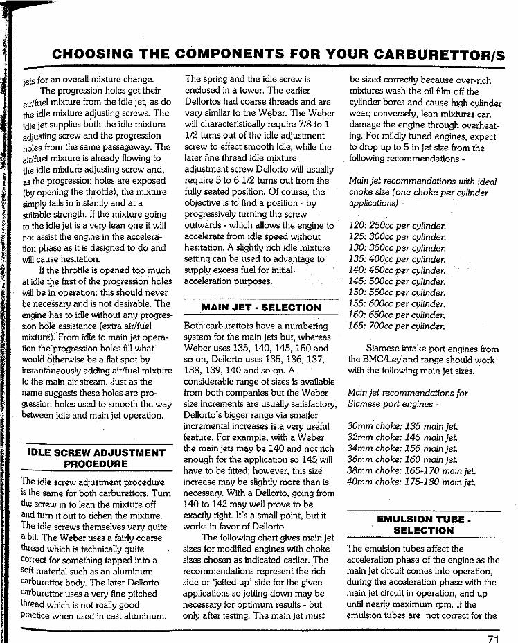
CHOOSING THE COMPONENTS FOR YOUR CARBURETTOR/S
jets for an overall mixture change. The progression holes get their
air/fuel mixture from the idle jet, as do the idle mixture adjusting screws. The idle jet supplies both the idle mixture adjusting screw and the progression holes from the same passageway. The air/fuel mixture is already flowing to the idle mixture adjusting screw and, as the progression holes are exposed (by opening the throttle), the mixture simply falls in instantly and at a suitable strength. If the mixture going to the idle jet is a very lean one it will not assist the engine in the accelera-tion phase as it is designed to do and will cause hesitation.
If the throttle is opened too much at idle the first of the progression holes will be in operation: this should never be necessary and is not desirable. The engine has to idle without any progres-sion hOie assistance (extra air/fuel mixture). From idle to main jet opera-tion th•f progression holes fill what would blherwise be a flat spot by instantaneously adding air/fuel mixture to the main air stream. Just as the name suggests these holes are pro-gression holes used to smooth the way between idle and main jet operation.
IDLE SCREW ADJUSTMENT PROCEDURE
The idle screw adjustment procedure is the same for both carburettors. Turn the screw in to lean the mixture off and turn it out to richen the mixture. The idle screws themselves vary quite a bit. The Weber uses a fairly coarse thread which is technically quite correct for something tapped into a soft material such as an aluminum carburettor body. The later Dellorto carburettor uses a very fine pitched thread which is not really good Practice when used in cast aluminum.
The spring and the idle screw is enclosed in a tower. The earlier Dellortos had coarse threads and are very similar to the Weber. The Weber will characteristically require 7/8 to 1 112 turns out of the idle adjustment screw to effect smooth idle, while the later fine thread idle mixture adjustment screw Dellorto wlll usually require 5 to 6 112 turns out from the fully seated position. Of course, the objective is to find a position - by progressively turning the screw outwards - which allows the engine to accelerate from idle speed without hesitation. A slightly rich idle mixture setting can be used to advantage to supply excess fuel for initial acceleration purposes.
MAIN JET • SELECTION
Both carburettors have a numbering system for the main jets but, whereas Weber uses 135, 140, 145, 150 and so on, Dellorto uses 135, 136, 137, 138, 139, 140 and so on. A considerable range of sizes is available from both companies butthe Weber size increments are usually satisfactory, Dellorto 's bigger range via smaller incremental increases is .a very useful feature. For example, with a Weber the main jets may be 140 and not rich enough for the application so 145 will have to be fitted; however, this size increase may be slightly more than is necessary. With a Dellorto, going from 140 to 142 may well prove to be exactly right It's a small point, but it works in favor of Dellorto.
The following chart gives main jet sizes for modified engines with choke sizes chosen as indicated earlier. The recommendations represent the rich side or 'jetted up' side for the given applications so jetting down may be necessary for optimum results - but only after testing. The main jet must
be sized correctly because over-rich mixtures wash the oil film off the cylinder bores and cause high cylinder wear; conversely, lean mixtures can damage the engine through overheat-ing. For mildly tuned engines, expect to drop up to 5 in jet size from the following recommendations -
Main jet recommendations with ideal choke size one choke per cylinder applications) -
120: 250cc per cylinder. 125: 300cc per cylinder. 130: 350cc per cylinder. 135: 400cc per cylinder. 140: 450cc per cylinder. 145: 500cc per cylinder. 150: 550cc per cylinder. 155: 600cc per cylinder. 160: 650cc per cylinder. 165: 700cc per cylinder.
Siamese intake port engines from the BMC/Leyland range should work with the following main jet sizes.
Main jet recommendations for Siamese port engines -
30mm choke: 135 main jet. 32mm choke: 145 main jet. 34mm choke: 155 main jet. 36mm choke: 160 main jet. 38mm choke: 165-170 main jet. 40mm choke: 175-180 main jet.
EMULSION TUBE SELECTION
The emulsion tubes affect the acceleration phase of the engine as the main jet circuit comes into operation, during the acceleration phase with the main jet circuit in operation, and up until nearly maximum rpm. If the emulsion tubes are not correct for the
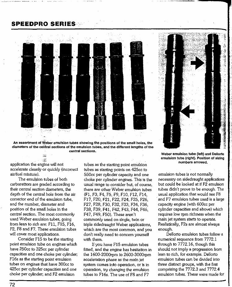
SPEEDPRO SERIES
An assortment of Weber emulsion tubes showing .the-positions of the small holes, the diameters of the centralsections of the emulsion tubes, and the different lengths of the
central sections.
application the engine will not accelerate cleanly or quickly (incorrect air/fuel mixture).
The emulsion tubes of both carburettors are graded according to their central section diameters, the depth of the central hole from the air corrector end of the emulsion tube, and the number, diameter and position of the small holes in the central section. The most commonly used Weber emulsion tubes, going from lean to rich are: Fll, f15F16, F2, F8 and F7. These emulsion tubes will cover most applications.
Consider FlS to be the starting point emulsion tube on engines which have 250cc to 325cc per cylinder capacities and one choke per cylinder; F16s as the starting point emulsion tubes on engines that have 300cc to 425cc per cylinder capacities and one choke per cylinder; and F2 emulsion
72
tubes as the starting point emulsion tubes as starting points on 425cc to 550cc per cylinder capacity and one choke per cylinder engines. This is the usual range to consider but, of course, there are other Weber emulsion tubes (F1,F3,F4,F5,F9,F10,F12,F14, F17, F20,F21,F22,F24,F25,F26, F27,F28,F30,F32,F33,F34,F36, F38,F39,F41,F42,F43,F44,F46, F47, F49, f50). These aren't commonly used on single, twin or triple sidedraught Weber applications, which are the most common, and you don't really need to concern yourself with them.
If you have F15 emulsion tubes fitted, and the engine has hesitation in the 1600-2000rpm to 2600-3000rpm acceleration phase as the main jet system comes into operation, or is in operation, try changing the emulsion tubes to F16s. The use of F8 and F7
Weber emulsion tube (left) and Dellorto emulsion tube (right). Position of sizing
numbers arrowed.
emulsion tubes is not normally necessary on sidedraught applications but could be looked at if F2 emulsion tubes didn't prove to be enough. The usual application that would see F8 and F7 emulsion tubes used is a large capacity engine (with 600cc per cylinder capacities and above) which requires low rpm richness when the main jet system starts to operate. Realistically, F2s are almost always enough.
Dellorto emulsion tubes follow a numerical sequence from 7772.1 through to 7772.16, though this should not imply a progression from lean to rich, for example. Dellorto emulsion tubes can be divided into three distinct groups, with the first comprising the 7772.3 and 7772.4 emulsion tubes. These were made for

CHOOSING THE COMPONENTS FOR YOUR CARBURETTOR/S
oHLB32/35 carburettors and, although they will fit, are not in our line up for all round DHLA use.
The next group comprises 7772.8 through to 7772.16 which were for use on emission control carburettors. The third group which overlaps slightly into the previously mentioned emission control carburettor group is that used for all general performance applications of 40mm, 45mm and 48mm Dellorto carburettors. This last group is listed here on the basis of going lean to rich for your convenience: 7772.10, 7772.8, 7772.2, 7772.1, 7772.14, 7772.5, 7772.7 and 7772.6.
7772.5 is no longer available from Dellorto, although there are literally thousands of these emulsion tubes available on the secondhand market. 7772.14 is an emission carburettor emulsion tube, but this is where it fits in the overall' scheme of things.
Consider 7772.10 or 7772.8 emulsion tubes as starting points on standard engines from 250cc up to 500ccper cylinder capacity and one choke per cylinder, and 7772.2, 7772.1 and 7772.14 emulsion tubes as the next steps on. The latter should also be considered as starting point emulsion tubes for modified small capacity per cylinder engines (250cc to 400cc per cylinder) with one choke per cylinder.
The final three emulsion tubes (7772.5, 7772.7 and 7772.6) are the most frequently used for modified and racing engines with cylinder capacities from 300cc tlhrough to 700cc. Consider the 7772.5 emulsion tube as the starting point for 300-500cc per cylinder modified engines, and 7772. 7 emulsion tubes for 400cc to 500cc per cylinder engines with one choke per cylinder. Use 7772.6 emulsion tubes on racing engines with 500cc per
lt:d
The complete range of Oellorto emulsion tubes from 1 to 16, left to right.
The 7772.4 tube Is on the left and the 7772.3 tube Is on the right.
cylinder capacities and up with one choke per cylinder. Use the leanest of these three emulsion tubes that gives your particular engine the best all round performance.
Siamesed intake port engines, as found in the BMC/Rover range, will run best with the following emulsion tubes-
F1617772. 7 for smaller engines (998cc-1098cc). Fl617772. 7 or richer F2!7772.6 for larger engines (1275cc and up).
AIR CORRECTOR SELECTION
The air corrector is used to tune top end performance but only over a very small range. Changes in air corrector size are made in increments of 10 at the very least and, more often, 20. Expect the range of air correctors to be from 150 to 230 for use with the main jets previously listed. Start with 160s and go leaner (a larger air corrector
73
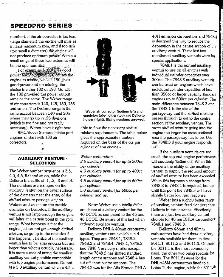
SPEEDPRO SERIES
number). If the air corrector is too lean (large diameter) the engine will miss as it nears maximum rpm, and if too rich (too small a diameter) the engine will not produce optimum pol.\leL Within a small range of these two extremes will be the optimim
engine to misfire,
good power and no missing, the choice is either 180 or 190. Go with the 180 provided the power output remains the same. The Weber range of air correctors is 140, 145, 150, 155 and so on. The Dellorto range is the same except between 140 and 205 where they go up in .25 divisions (which is too fine and not really necessary). Weber have it right here.
BMC/Rover Siamese intake port engines all start witp 180 air correctors.
AUXILIARY VENTURI • SELECTION
The Weber number sequence is 3.5, 4.0, 4.5, 5.0 and so on, while the Dellorto is a suffix of .1, .2, .3 and .4. The numbers are stamped on the auxiliary venturi on the outer surface of the diameter near the entry of the air/fuel mixture passage way on Webers and cast in on the outside diameter on Dellortos. If the auxiliary venturi is not large enough the engine will falter at a certain point in the rpm range. What happens is that the engine just cannot get enough air/fuel mixture, so go up to the next size if this happens. The size of the auxiliary venturi has to be large enough but not larger than what is actually necessary. It is more a case of fitting the smallest auxiliary venturi possible compatible with top engine performance. Do not fit a 5.0 auxiliary venturi when a 4.5 is
Weber air corrector (bottom left) and emulsion tube holder (\op) and Dellorto holder (right). Sizing numbers arrowed.
able to flow the necessary air/fuel mixture requirements. The table below gives the approximate numbers required on the basis of the ccs per cylinder of any engine -
Weber carburettors -3.5 auxiliary venturi for up to 300cc per cylinder. 4.0 auxiliary venturi for up to 400cc per cylinder. 4.5 auxiliary venturi for up to 500cc per cylinder. 5.0 auxiliary venturi for 500cc per cylinder and up.
Note: Weber use a totally differ-ent shape of auxiliary venturi for the 40 DCOE as compared to the 45 and 48 DCOE. Be aware of this fact when ordering auxiliary venturis.
Dellorto DHLA 40mm carburettor auxiliary venturis are available in 4 types. They are: 7848.1, 7848.2, 7848.3 and 7848.4. 7848.1, 7848.2 and 7848.4 are very similar except that the 7848.2 has slotted standard length centre sections and 7848.4 has cut off short centre sections. The 7848.2 was for the Alfa Romeo DHLA
40H emission carburettors and 7848.4 is designed this way to reduce the depression in the centre section of the auxiliary venturi. These last two mentioned auxiliary venturis were for special applications.
7848.1 is the normal auxiliary venturi to use on all engines with individual cylinder capacities over 300cc. The 7848.3 auxiliary venturis can be used on engines which have individual cylinder capacities of less than 350cc or larger capacity standard engines up to 500cc per cylinder. The main difference between 7848.3 and the 7848.1 is the size of the passageway that the air/fuel mixture passes through to get to the centre ·section of the auxiliary venturi. The more air/fuel mixture going into the engine the larger the cross sectional area the passageway has to be. Use the 7848.3 if your engine responds well.
If the auxiliary venturis are too small, the top end engine performance will suddenly 'flatten off. When this happens the ability of the auxiliary venturi to supply the required amount of air/fuel mixture has been exceeded. When this happens a change from 7848.3 to 7848.1 is required, but up until this point the 7848.3 will have slightly better low rpm response.
Weber has a slightly better range of auxiliary venturi feed slot sizes than Dellorto in this instance. Effectively, there are just two auxiliary venturi choices for 40mm D HLA carburettors: 7848.1 and 7848.3.
Dellorto 45mm and 48mm carburettors have had three auxiliary venturis available for them, in sizes 8011.1,8011.2 and 8011.3. Of these, the 8011.1 is the most commonly used, the other two being specials for Lotus. The 8011.2s were for the DHLA45M carburettors fitted to a Lotus Turbo engine, while the 8011.45
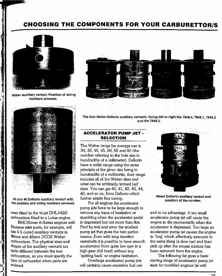
CHOOSING THE COMPONENTS FOR YOUR CARBURETTOR/S
Weber auxiliary venturi. Position of sizing numbers arrowed.
45 and 48 Dellorto auxiliary venturi with the position and sizing numbers arrowed.
were fitted to the tri-jet DHLA45D carburettors fitted to a Lotus engine.
BMC/Rover A-Series engines with Siamese inlet ports, for example, will use 4. 5 coded auxiliary venturis in 40mm and 45mm DCOE Weber carburettors. The physical sizes and shapes of the auxiliary venturis are quite different between the two carburettors, so you must specify the type of carburettor when parts are ordered.
The lour 40mm Dellorto auxiliary venturis. Going left to right the 7848.4, 7848.1,7848.2 and the 7848.3.
ACCELERATOR PUMP ,JET· SELECTION
The Weber range for average use is 30, 35, 40, 45, 50, 55 and 60 (the number referring to the hole size in hundredths of a millimeter). Dellorto have a wider range using the same principle of the given size being in hundredths of a millimeter, their range includes !Ill of the Weber sizes and what can be arbitrarily termed half sizes. You can get 40, 41, 42, 43, 44, 45, and so on, from Dellorto which further assists fine tuning.
For all engines the accelerator pump jets have to be large enough to remove any trace of hesitation or stumbling when the accelerator pedal is depressed but not more than this. Find by trial and error the smallest pump jet that gives the best perfor-mance. Even with long duration camshafts itis possible to have smooth acceleration from quite low rpm in a high gear (full load) without any 'spitting back' or engine hesitation.
Overlarge accelerator pump jets will certainly cause excessive fuel use
40mm Dellorto auxiliary venturi and position of the number.
and to no advantage. A too small accelerator pump jet will cause the engine to die momentarily when the accelerator is depressed. Too large an accelerator pump jet causes the engine to 'bog' which effectively amounts to the same thing (a slow car) and then pick up after the excess mixture has been removed from the engine.
The following list gives a basic starting range of accelerator pump jet sizes for modified engines (ie with
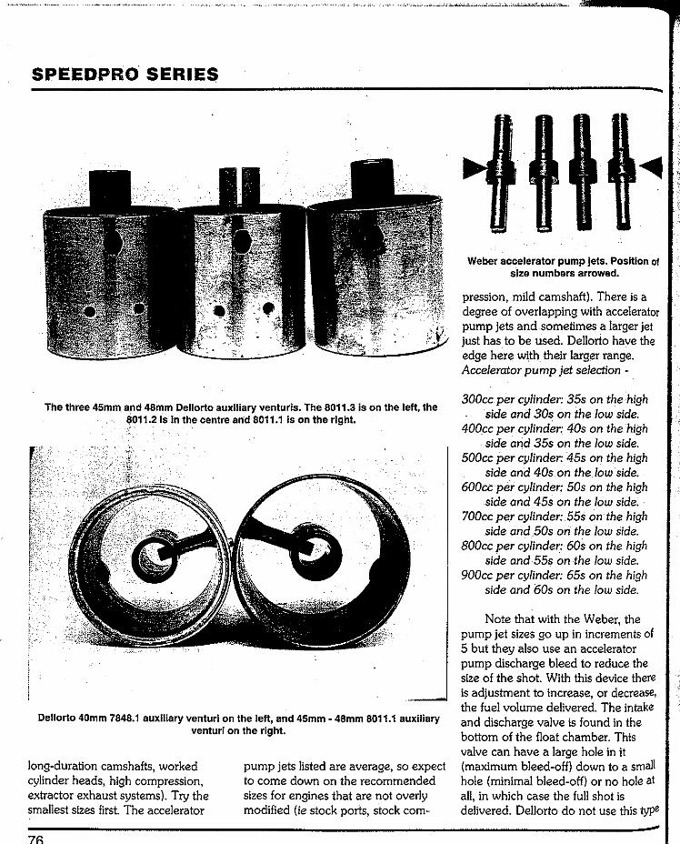
SPEEDPRO SERIES
The three 45mm and 48mm Dellorto auxiliary venturis. The 8011.31s on the left, the ~011.21s In the centre arid 8011.1 is on the right.
Dellorto 40mm 7848.1 auxiliary venturi on the left, and 45mm- 48mm 8011.1 auxiliary venturi on the right.
long-duration camshafts, worked cylinder heads, high compression, extractor exhaust systems). Try the smallest sizes first. The accelerator
pump jets listed are average, so expect to come down on the recommended sizes for engines that are not overly modified (ie stock ports, stock com-
Weber accelerator pump jets. Position of size numbers arrowed.
pression, mild camshaft). There is a degree of overlapping with accelerator pump jets and sometimes a larger jet just hasto be used. Dellorto have the edge here with their larger range. Accelerator pump jet selection -
300cc per cylinder: 35s on the high side and 30s on the low side.
400cc per cylinder: 40s on the high side and 35s on the low side.
500cc per cylinder: 45s on the high side and 40s on the low side.
600cc per cylinder: 50s on the high side and 45s on the low side.
700cc per cylinder: 55s on the high side and .50s on the low side.
800cc per cylinder: 60s on the high side and 55s on the low side.
900cc per cylinder: 65s on the high side and 60s on the low side.
Note that with the Weber, the pump jet sizes go up in increments of 5 but they also use an accelerator pump discharge bleed to reduce the size of the shot. With this device there is adjustment to increase, or decrease, the fuel volume delivered. The intake and discharge valve is found in the bottom of the float chamber. This valve can have a large hole in it (maximum bleed-off) down to a small hole (minimal bleed-off) or no hole at all, in which case the full shot is delivered. Dellorto do not use this type
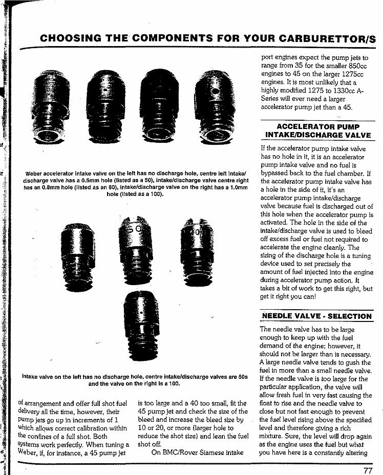
CHOOSING THE COMPONENTS FOR YOUR CARBURETTOR/S
Weber accelerator Intake valve on the left has no discharge hole, centre left intake/ discharge valve has a 0.5mm hole (listed as a 50), intake/discharge valve centre right has an 0.8mmhole (listed as an 80), intake/discharge valve on the right has a 1.0mm
hole (listed as a 1 00).
Intake valve on the left has no discharge hole, centre intake/discharge valves are 50s and the valve on the right Is a 100.
of arrangement and offer full shot fuel delivery all the time, however, their PUmp jets go up in increments of 1 Which allows correct calibration within the confi~es of a full shot. Both systems work perfectly. When tuning a Weber, if, for instance, a 45 pump jet
is too large and a 40 too small, fit the 45 pump jet and check the size of the bleed and increase the bleed size by 10 or 20, or more (larger hole to reduce the shot size) and lean the fuel shot off.
On BMC/Rover Siamese intake
port engines expect the pump jets to range from 35 for the smaller 850cc engines to 45 on the larger 1275cc engines. It is most unlikely that a highly modified 1275 to 1330cc A-Series will ever need a larger accelerator pump jet than a 45.
ACCELERATOR PUMP INTAKE/DISCHARGE VALVE
If the accelerator pump intake valve has no hole in it, it is an accelerator pump intake valve and no fuel is bypassed back to the fuel chamber. If the accelerator pump intake valve has a hole in the side of it, it's an accelerator pump intake/discharge valve because fuel is discharged out of this hole when the accelerator pump is activated. The hole in the side of the intake/discharge valve is used to bleed off excess fuel or fuel not required to accelerate the engine cleanly. The sizing of the discharge hole is a tuning device used to set precisely the amount of fuel injected into the engine during accelerator pump action. It takes a bit of work to get this right, but get it right you can!
NEEDLE VALVE· SELECTION
The needle valve has to be large enough to keep up with the fuel demand of the engine; however, it should not be larger than is necessary. A large needle valve tends to gush the fuel in more than a small needle valve. If the needle valve is too large for the P.articular application, the valve will allow fresh fuel in very fast causing the float to rise and the needle valve to close but not fast enough to prevent the fuel level rising above the specified level and therefore giving a rich mixture. Sure, the level will drop again as the engine uses the fuel but what you have here is a constantly altering
77
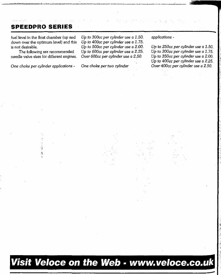
SPEEDPRO SERIES
fuel level in the float chamber (up and down over the optimum level) and this is not desirable.
The following are recommended needle valve sizes for different engines.
One choke per cylinder applications -
Up to 300cc per cylinder use a 1.50. Up to 400cc per cylinder use a 1.75. Up to 500cc per cylinder use a 2.00. Up to 600cc per cylinder use a 2.25. Over 600cc per cylinder use a 2.50.
One choke per two cylinder
applications -
Up to 250cc per cylinder use a 1.50. Up to 300cc per cylinder use a 1. 75. Up to 350cc per cylinder use a 2.00. Up to 400cc per cylinder use a 2.25. Over 400cc per cylinder use a 2.50.
Visit Veloce on the Web. www.veloce.co.uk
Chapter 5 Manifold preparation & carburettor fitting
INTAKE MANIFOLD· CHECKING & PREPARATION
Good progression, snappy mid-range performance and optimum top end power requires identical throttle opening in multiple carburettors from idle to full throttle. There is no substitute for absolute accuracy.
Intake manifold alignment is critical when linked throttle arms are USed and this aspect of carburettor tuning is vitallf maximum perfor-mance is required from engines with two or more carburettors. To take a common situation with twin Sidedraughts on an in-line four-cylinder engine, the carburettor butterflies can be set perfectly at idle and just off idle yet, at half throttle and more, one set of butterflies can start to lag behind. At full throttle the situation is not usually so bad because the throttle spindle obscures the actual butterfly through its own physical size, so a bit of incorrect butterfly angle
between the carburettors does not always affect wide open throttle performance but the mid-range power will however be down in this situation. A common fault that causes butterflies to become unsynchronized at part throttle is poor intake stud to. carburettor body alignment. This is a seriuos indictment of some manufac-turers of intake manifolds who should know how important this feature is.
The importance of stud alignment
All intake manifolds must be checked for accuracy. There are various multiple carburettor linkages available but the most common is the linked throttle adjuster arrangement. However, this system wlll only be as good as the alignment of the intake manifold. If your manifold does not prove to be accurately made return it to the manufacturer for replacement or have the offending studs repositioned.
The following simple test can be carried out anywhere using an engineer's rule or a straight edge. If the manifold does not have any studs fitted just screw in some bolts. Lay the rule edge along the studs (see photo). If the studs are out you will be able to see it at a glance. The maximum allowable error is about 0.2Smm (O.OlOin) but there should really be no per;:eptible alignment error.
If your manifold has two or three stud holes out by a reasonably small amount (lmm/0.040in) the easiest way of having a stud hole repositioned is to either 1) have the complete hole filled by TlG welding, reface the manifold surface and then re-drill and tap the hole in the correct position or 2) move the centre of the hole over by offset boring using a milling machine and fit a Helicoil which will correct the situation. Clearly the best thing to do is check the manifold properly before buying it and make sure you get a good one in the first place.

SPEEDPRO SERIES
With the linked type of joining system the carburettors must be parallel (within 0.1mm/0.004in) to the· intake manifold when O-ring gasketsare in place and the studs nuts arealltightened. They must also be perfectlyin-line when looking straight down thethrottle bores, or spindle to spindle, ininboth planes.
Another method of throttle action involves pushrods with balls and sockets at each end. This is quite common on six-cylinder in-line en-gines and comprises a sturdy, full length throttle bar with lever arms positioned directly above each carburettor' s throttle arm. Once again componentaccuracy plays a part in making sure all aoperating in unison. lever arms must all be (within O.lmm/0.004in). Otherwiseone arm has a shorter pitch, for instance, that particular carburettor will have advanced butterflyopening. The balls and sockets haveto be kept in perfect condition if settings are to be reliably maintained. Manifold stud alignment is less critical when com-pared to the direct linkage system but, ideally, all intake manifolds should have accurate stud alignment.
Carburettor checking fit It is actually better to fit the carburettors to the manifold off the engine. With the integrity of the intake manifold checked (stud alignment and face flatness) fit all studs to the manifold and use Loctite (or any other suitable retaining compound) on the threads. Torque the studs to about 7 foot pounds using locked nuts. Check that all studs are at 90 degrees to the manifold face in all planes. This is to ensure that the carburettors will fit over the studs easily. All studs must protrude from the manifold's surface a
Use a straight edge to check that the studs are In alignment.
The typical twln-sldedraught manifold. Note how some of the carburettor mounting studs are angled and how, In the second picture, the carburettors (a Weber and a
Dellorto).won't slide over the studs.

MANIFOLD PREPARATION & CARBURETTOR FITTING
minimum of 38mm (1.5in). The top ones should not be longer than 38mm but the bottom ones can be up to 40mm (1.57in) as there is plenty of clearance. Fit a carburettor to each set of studs. It must fit easily and not bind on the studs all the way down to the manifold surface.
Anti-vibration mountings Because they are susceptible to fuel frothing, Weber and Dellorto carburettors are installed with anti-vibration0-ring gaskets and related
componentry. Kits comprise the large 0-ring gasket (one per choke) and rubber grommets, metal caps and nylock nuts. In some applications "Thackery" washers (short flat wound coil springs) are used beneath the carburettor securing nuts and these washers apply tension, via the carburettor body, to the 0-rings.
Engines fitted with Webers or Dellortos as original equipment usually feature moulded rubber mounting blocks between the carburettor/s and the manifold. These blocks are excel-lent, but cannot usually be adapted to
Simply excellent Manillow made, steel inlet manifold for a single sldedraught
carburettor application for Siamese intake port engines (A-Series). it doesn't get any
better than this, and it's simple.
81
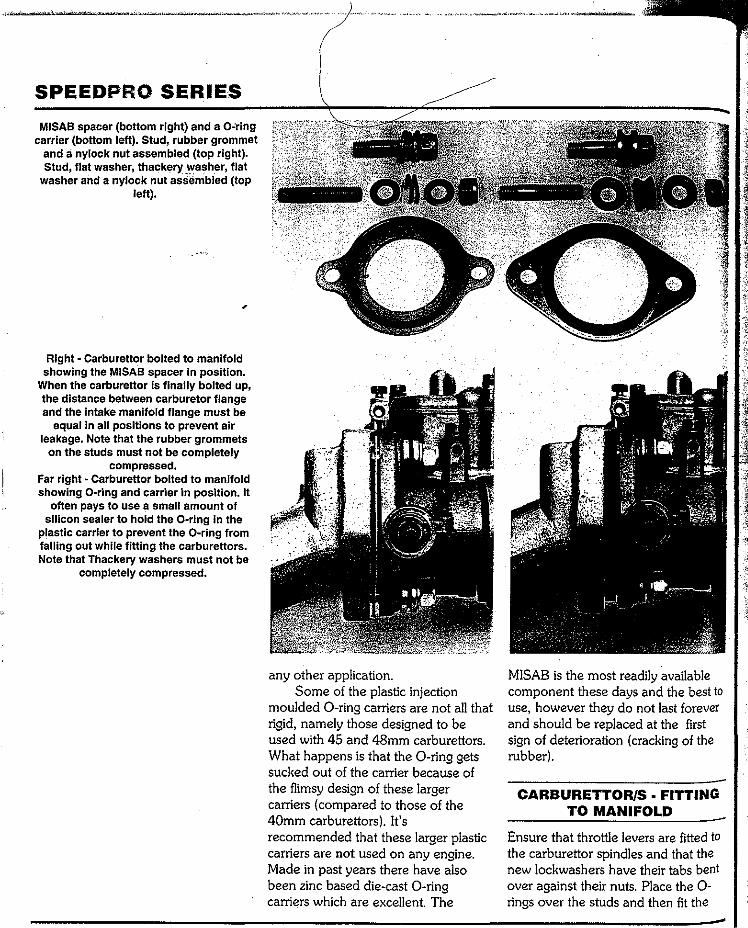
SPEEDPRO SERIES MISAB spacer (bottom right) and a O-ring
carrier (bottom left). Stud, rub.ber grommet and a nylock nut assembled (top right). Stud, flat washer, thackery washer, flat
washer and a nylock nut assembled(top left).
Right- Carburettor bolted to manifold showing the MISAB spacer In position.
When the carburettor is finally bolted up, the distance between carburetor flange and the Intake manifold flange must be
equal in all positions to prevent air leakage. Note that the rubber grommets
on the studs must not be completely compressed.
Far right- Carburettor bolted to manifold showing 0-ring and carrier in position. It
often pays to use a small amount of silicon sealer to hold the 0-ring in the
plastic carrier to prevent the 0-ring from falling out while fitting the carburettors. Note that Thackery washers must not be
completely compressed.
any other application. Some of the plastic injection
moulded 0-ring carriers are not all that rigid, namely those designed to be used with 45 and 48mm carburettors. What happens is that the 0-ring gets sucked out of the carrier because of the flimsy design of these larger carriers (compared to those of the 40mm carburettors). It's recommended that these larger plastic carriers are not used on any engine. Made in past years there have also been zinc based die-cast 0-ring carriers which are excellent. The
MISAB is the most readily available component these days and the best to use, however they do not last forever and should be replaced at the first sign of deterioration (cracking of the rubber).
CARBURETTOR/S FITTING TO MANIFOLD
Ensure that throtile levers are fitted to the carburettor spindles and that the new Jockwashers have their tabs bent over against their nuts. Place the 0-rings over the studs and then fit the
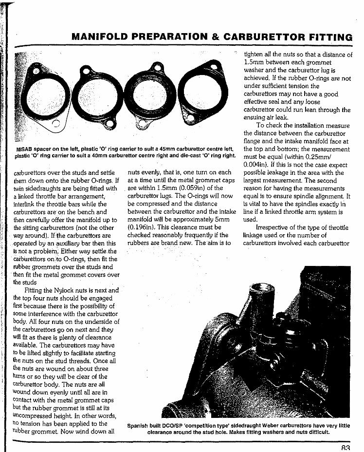
MANIFOLD PREPARATION & CARBURETTOR FITTING
MISAB spacer on the left, plastic '0' ring carrier to suit a 45mm carburettor centre left, plastic '0' ring carrier to suit a 40mm carburettor centre right and die·cast '0' ring right.
carburettors over the stuc!s and settle them down onto the rubber 0-rings. If twin sidedraughts are being fitted with a linked throttle bar arrangement, interlink the throttle bars while the carburettors are on the bench and then carefully offer the manifold up to the sitting carburettors (not the other way around). If the carburettors are operated by an auxiliary bar then this is not a problem. Either way settle.the carburettors on.:to 0-rings, then fit the rubber grommets over the studs and then fit the metal grommet covers over the studs
nuts evenly, that is, one turn on each at a time until the metal grommet caps are within 1.5mm (0.059in) of the carburettor lugs. The 0-rings will now be compressed and the distance between the carburettor and the intake manifold will be approximately 5mm (0.196in). This clearance must be checked reasonably frequently if the rubbers are brand new. The aim is to
tighten all the nuts so that a distance of 1.5mm between each grommet washer and the carburettor lug is achieved. If the rubber 0-rings are not under sufficient tension the carburettors may not have a good effective seal and any loose carburettor could run lean through the ensuing air leak.
To check the installation measure the distance between the carburettor flange and the intake manifold face at the top and bottom; the measurement must be equal (within 0.25mm/ 0.004in). If this is not the case expect possible leakage in the area with the largest measurement. The second reason for having the measurements equal is to ensure spindle alignment. It is vital to have the spindles exactly in line if a linked throttle arm system is used.
Irrespective of the type of throttle linkage used or the number of carburettors involved each carburettor
Fitting the Nylock nuts is next and the top four nuts should be engaged first because there is the possibility of some interference with the carburettor body. All four nuts on the underside of the carburettors go on next and they will fit as there is plenty of clearance available. The carburettors may have to be lifted slightly to facilitate starting the nuts on the stud threads. Once all the nuts are wound on about three turns or so they will be clear of the carburettor body. The nuts are all Wound down eyenly until all are in contact with the rnetal grommet caps but the rubber grommet is still at its Uncompressed height. In other words, no tension has been applied to the rubber grommet. Now wind down all
Spanish built DCOISP 'competition type' sldedraught Weber carburettors have very little clearance around the stud hole. Makes fitting washers and nuts difficult.
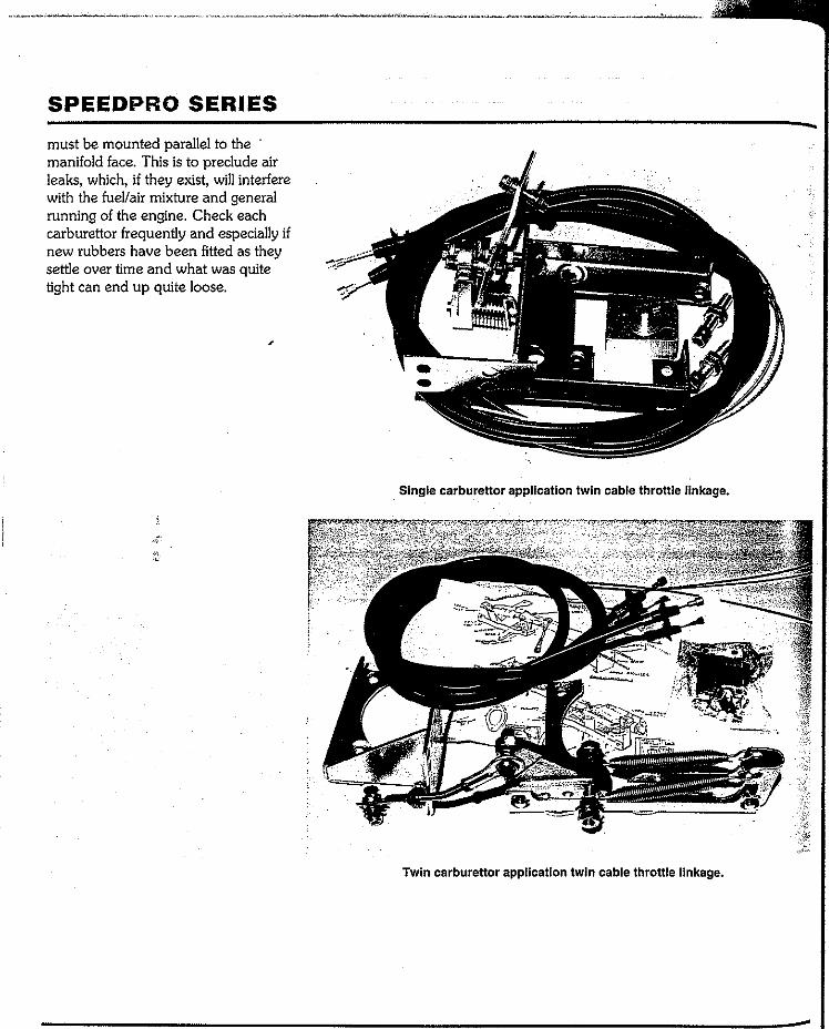
SPEEDPRO SERIES
must be mounted parallel to the manifold face. This is to preclude air leaks, which, if they exist, will interfere with the fuel/air mixture and general running of the engine. Check each carburettor frequently and especially if new rubbers have been fitted as they settle over time and what was quite tight can end up quite loose.
Single carbureltor application twin cable throttle linkage.
Twin carburettor application twin cable throttle linkage.
Chapter6 Testing & set-up
What follows is a tuning sequence that can be appliedto any Weber/Dellorto sidedraught carburettorinstallation irrespective ofhow many carburettors are involved. From this point on only tuning technique is discussed. Your carburettor/s should now be fitted with the chokes, venturis and jets chosen from the recommendations given in chapter 4 and, although alterations may well have to be made, the basic set-up should be nearly correct.
IDLE SPEED
The duration and overlap of the camshaft has a huge affect on the idling speed. The range of reasonable idling speeds for different camshaft configurations is as follows.
Standard camshaft (about 240 degrees duration, 30 degree overlap): 500rpm
Mild performance camshaft (265 to 270 degrees duration, 50 degrees
overlap): 800rpm. Medium performance camshaft
(270 to 290 degrees duration, 70 degrees overlap): 1 OOOrpm.
Racing camshaft (290 to 320 degrees duration, 90 degrees overlap): 1200 rpm.
FUEL LEVEL & NEEDLE VALVE OPERATION·
CHECKING
Make sure float levels are correctly adjusted; the float level setting procedure is given in chapter 2.
If the engine has a mechanical fuel pump it should be cranked over or, if equipped with an electric fuel pump, the ignition turned on to allow the carburettor float bowls to fill with fuel. Check to see whether the needle valves are actually shutting off. The first indication of flooding will be fuel pouring out of the fuel bowl vent. This can happen with new carburettors but
is more usual with used carburettors that have not been rebuilt correctly. Flooding can be caused by dirt or debris in the needle valve body which prevents the needle from seating. With older, or badly rebuilt, carburettors the problem is more likely to be that the needle's tapered section is worn (grooved). Conversely, if the fuel bowls do not fill up, the needle could be jammed in the off position (dirt) and not allow the fuel to go into the float chamber. It is also possible for fuel line debris to block the mouth of the valve.
In the case of multiple carburettors, the next check is to remove the carburettor tops to see if the fuel levels of each carburettor look the same. Despite the fact that the floats are set to exacting measurements the ultimate aim of the procedure is to ensure that the fuel levels of each carburettor are the same and within optimal range on multiple carburettor set-ups. If necessary, set
85

SPEEDFRO SERIES
the floats of individual carburettors to give identical fuel levels, even if it means setting the floats to slightly non-standard settings.
THROTTLE INITIAL ADJUSTMENT AND
SYNCHRONIZATION
This involves the setting of each set of butterflies so that, no matter how many carburettors are fitted, all will beflowing the same amount of air at idle and throughout their entire operating range. The engine has to be running to synchronize the carburettors so the next thing that has to be done is get the engine running so that adjustments can be made.
Throttle arm fit Note that each carburettor has a throttle arm of som'e description and this throttie arm fitson to the spindle at that point wher~1two flats have been machined on it. Tli~ throttie arm has a precision fitting slot in it that allows the throttie arm to be a tight fit on to the spindle. If the throttie arm is a used one, check the fit of the throttie arm on to the spindle. The fit must be tight. If it isn't, the carburettor could have been used with the securing nut loose. This will mean that, although the nut and washer are tight, the throttle arm and spindle are not accurately located and could move. If this happens the carburettor will go out of synchronization. Replace any throttie arm that is not a good fit on the spindle. (An alternative to replacing the throttle arm is to braise the flats of the throttle arm slot and then, using needle files, file the slot out to fit the spindle. If the spindle is also worn this is often the only way of restoring the fit unless the spindle and throttie arm is to be replaced).
Throttle initial setting (single carburettor)
On single carburettor set-ups, simply turn the throttie arm adjusting screw clockwise until you see the throttie arm just begin to move and then turn the screw a quarter turn. If you are not sure of the throttie arm's state, turn the adjusting screw anti-clockwise and note if the arm moves. If the arm moves up then the throttie was cracked open. Turn the adjusting screw until the throttle arm stops moving. Slowly turn the adjusting screw clockwise until it contacts the throttle arm and then tum the adjusting screw a further quarter turn.
Throttle • initial set-up & synchronization (multiple
carburettors) For multiple carburettors linked by individual pushrods with socketed balls, undo the linkage arms on the main throttie bar. Check that the rods from socket center to socket center are equal in length (to within O.Smm/ 0.020in). Turn each throttle arm adjusting screw anti-clockwise until there is no movement of the throttie arm and then tum each throttie arm adjusting screw clockwise until it just cont<icts the throttle arm. Now tum the throttle arm adjusting screw of each carburettor a quarter turn clockwise. Go to the main throttie arm and put light downward hand pressure on each throttle rod in turn and tighten to the securing nut. Do this to each throttie rod so that there is littie or no play in the mechanism. The throttie synchronization will not be exactly right but close enough to start the engine.
For multiple carburettors using the more common linked throttle arm joining mechanism, turn the synchro-nizing screw on the joining link anti-clockwise until the end of the screw is
clear of the central lever. Turn the adjusting screw on the throttie arm anti-clockwise until the arm does not move. Then tum the throttie arm adjusting screw clockwise until it just contacts the throttie arm. Now turn the synchronizing adjustment screw clockwise until it contacts the central lever. Go back to the throttie arm adjusting screw and tum it a quarier turn. The throttie is now sufficiently synchronized to start the engine. At this point the throttie will work and all throttie arms will have a small amount of throttie wound on to effect an idle. The idle may not be smooth but it will be an idle.
IDLE MIXTURE INITIAL ADJUSTMENT
Turn the idle mixture adjustment screws on Webers· out 1 114 turns from the lightly seated fully in position. Tum the idle mixture adjustment screws on Dellortos out 3 1/2 turns from the lightly seated fully in position. The engine will start on this setting, but it may not run all that smoothly. When the engine has been warmed up and the idle speed screw set to give 1000rpm (or whatever rpm the engine will idle at) turn all of the idle mixture adjusting screws out a further 114 turn for Webers and a further 1/2 tum for Dellortos (that's a total of 1 112 turns for the Webers and 4 turns for the Dellortos). If the idle smoothness improves and the engine speed increases reset the idle speed back to 1000rpm (or whatever the original idle speed was).
Conversely, if the idle smoothness worsens and the idle speed rpm drops, turn the idle mixture adjustment · screws back to what they were (1 1/4 for Webers and 3 1/2for Dellortos). With engine basically stabilised then
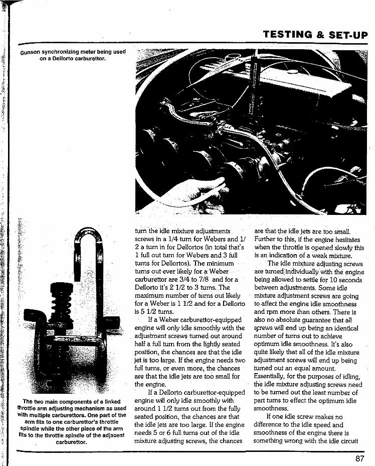
Gunson synchronizing meter being used on a Dellorto carburettor.
The two main components of a linked throttle arm adjusting mechanism as used With multiple carburettors. One part of the
arm fits to one carburettor's throttle spindle while the other piece of the arm
fils to the throttle spindle of the adjacent carburettor.
tum the idle mixture adjustments screws in a 114 turn for Webers and 1/ 2 a tum in for Dellortos (in total thats 1 full out tum for Webers and 3 full turns for Dellortos). The minimum turns out ever likely for a Weber carburettor are 3/4 to 718 and for a Dellorto it's 2 112 to 3 turns. The maximum number of turns out likely for a Weber is 1 1/2 and for a Dellorto is 5 112 turns.
If a Weber carburettor-equipped engine will only idle smoothly with the adjustment screws turned out around half a full tum from the lightly seated position, the chances are that the idle jet is too large. If the engine needs two full turns, or even more, the chances are that the idle jets are too small for the engine.
If a Dellorto carburettor-equipped engine will only idle smoothly with around 1 112 turns out from the fully seated position, the chances are that the idle jets are too large. If the engine needs 5 or 6 full turns out of the idle mixture adjusting screws, the chances
TESTING & SET·UP
are that the idle jets are too small. Further to this, if the engine hesitates when the throttle is ()pened slowly this is an indication of a weak mixture.
The idle mixtureadjusting screws are turned individually with the. engine being allowed to settle for 10 seconds between adjustments. Some idle mixture adjustment screws are going to .affect the engine idle smoothness and rpm more than others. There is also no absolute guarantee that all s.s;rews will end up being an identical number of turns out to achieve optimum idle smoothness. It's also quite likely that all of the idle mixture adjustment screws will end up being turned· out an equal amount. Essentially, for the purposes of idling, the idle mixture adjusting screws need to. be turned out the least number of part turns to effect the optimum idle smoothness.
If one idle screw makes no difference to the idle speed and smoothness of the engine there is something wrong with the idle circuit
87
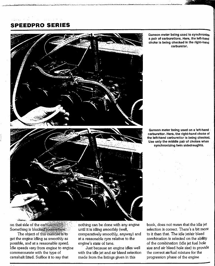
SPEEDPRO SERIES
Something is blocked somewhereThe objectof
get the engine idling as smoothly as possible, and at a reasonable speed. Idle speeds vary from engine to engine commensurate with the type of camshaft fitted. Suffice it to say that
nothing can be done with any engine until it is idling smoothly (well, comparatively smoothly, anyway) and at a reasonable rpm relative to the engine's state of tune.
Just because an engine idles well with the idle jet and air bleed selection made from the listings given in this
Gunson meter being used to synchronize a pair of carburettors. Here, the left~hana choke Is being checked In the right-hand
carburetor.
Gunson meter being used on a lett~hand · carburettor. Here, the right-hand choke of the left-hand carburettor is being checked. Use only the middle pair of chokes when
synchronizing twin sidedraughts.
book, does not mean that the idle jet selection is correct. There's a bit more to it than that. The idle jet/air bleed combination is selected on the ability of the combination (idle jet fuel hole size and air bleed hole size) to provide the correct air/fuel mixture for the progression phase of the engine

Main throttle bar (arrowed) with push rod connected. The bar must be strong and mounted in good bearings. Each oflhe
actuating arms (arrowed) must be of the same length (bar center to ball).
A typical double-socket pushrod as commonly used on throttle bar systems. It
is essential that the soCket centre-to-socket centre dimensions of all push rods
are Identical.
acceleration from idle. That is the air/ fuel requirement for smooth engine acceleration the instant that the· butterfly is moved from the idle stop, exposing the progression holes :as they become downstream of the butterfly (as the butterfly sweeps over the progression holes, they come under engine vacuum) and air/fuel mixture is passed through the progression holes and into the engine. With the engine idling reasonably well, the next stage is throttle synchronisation.
THROTTLE (LINKED THROTTLE ARM TYPE)
. FINAL SYNCHRONIZATION
The linked throttle arm system is the ·most common for· twin sidedraught installations. With the engine warmed-up and running at approximately 1200rpm, the two adjacent chokes of each carburettor pair are checked for air flow using a meter, of which there are several on the market. These meters give direct readings via a scale which is a part of the meter. This the only way to go for a consistently
TESTING & SET·UP
accurate result. On these linked throttle arm
systems there will be only one screw for adjusting the idle speed (on the basis of moving the throttle arm away from the carburettor body) and this is on the left-hand carburettor (looking at the carburettors intakes). Other carburettors are linked to this arm via the synchronizing screw mechanism. The synchronizing screw is used to equalize the airflow of the adjacent carburettor/s to the left-hand carburettor. The left-hand carburettor is the lead carburettor and the other is adjusted to match it. The adjusting screw of the right-hand carburettor can· be adjusted to cause the right-hand carburettor to receive more or less air than the adjacent carburettor and cause engine rpm to rise or fall. Turning the adjusting screw clockwise increases the airflow into the right-hand carburettor and turning the adjusting screw anti-clockwise reduces the airflow. When the linkage is synchronized correctly, the throttle arm adjusting screw on the left-hand carburettor is used to adjust the idle speed of the engine.
89
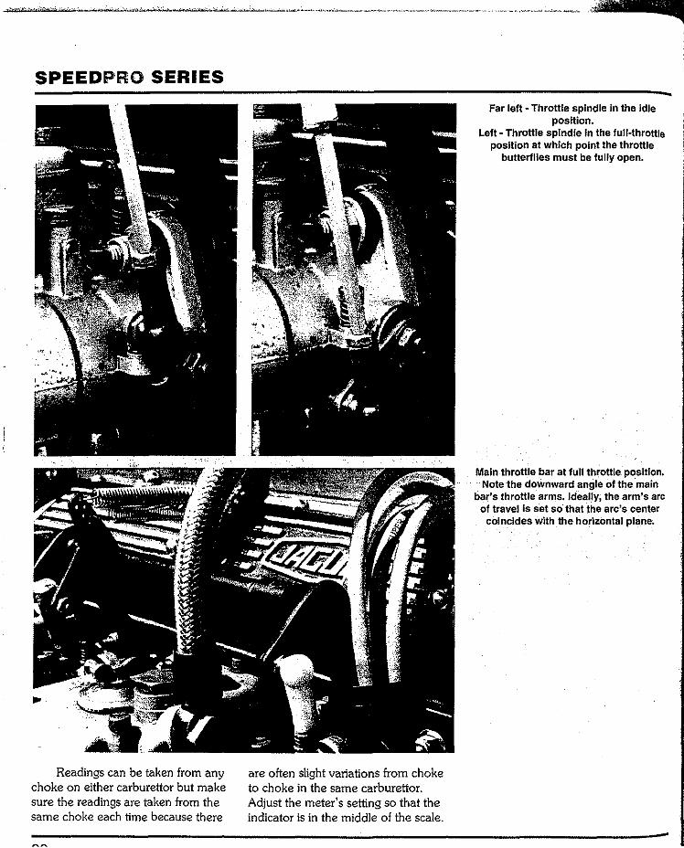
SPEEDPRO SERIES
Readings can be taken from any choke on either carburettor but make sure the readings are taken from the same choke each time because there
are often slight variations from choke to choke in the same carburettor. Adjust the meter's setting so that the indicator is in the middle of the scale.
Far left- Throttle spindle in the idle position.
Left- Throttle spindle In the full-throttle position at which point the throttle
butterflies must be tully open.
Main throttle bar at full throttle position. Note the doWnward angle of the ·main
bar's throttle arms. Ideally, the arm's arc of travel is set so· that the arc's center
coincides with the horizontal plane.

. . . ,·.:·
oo not leave the meter over the carburettor choke for more than five seconds. Check each carburettor for flow and then adjust the second carburettor to equal the airflow of the !eft-hand 'datum' carburettor. If, for instance, the meter shows that the right-hand carburettor is flowing more air, tum the synchronizing screw of the adjacent carburettor anti-clockwise a small amount and take another pair of readings with the meter. Carry on adjusting the right-hand carburettor until the readings are equal. Flow meters are quite accurate and allow virtually perfect throttle synchroniza-tion to be achieved. Note: expect to have to check and re-adjust the synchronization every six months on a road car and before every meeting on a competition car.
THROTTLE (BAR & PUSH ROD TYPE) FINAL
SYNCftRONIZATION
For multiple carburettors operated by a main throttle bar with arms and pushrods (balls and sockets at each end), the idle is set by undoing the clamps on the arms of the main throttle bar and adjusting each carburettor in tum. Each carburettor . will have its own throttle adjustment screw and arm. With the engine fully, warmed and idling, place the meter over a choke on ·each adjacent carburettor and take a reading. Tum the screw(s) of the carburettor(s) that has the lowest reading on the scale and increase the flow of that carburettor(s) by turning the adjustment screw clockwise. When all carburettors are equal in air flow check the rev counter to see what the rpm is. If the revs are too high the rpm will have to be reduced by turning out each throttle adjusting screw an equal
TESTING & SET·UP
"Motometer" beinQ used. This type of flow meter fits over the end of the trumpet. The sight reading glass is integral with the meter.
amount to cut the airflow down. Use the meter to check each carburettor so that when the engine is finally idling at the· correct speed each carburettor is flowing exactly the same amount of air. The next stage is to synchronize the carburettors' throttles off idle.
It is essential to get an equal amount of air through each carburettor right up to and including full throttle. To achieve this the pushrods must each be identical in length (socket-to-socket) as must all the actuating arms of the throttle rod and all the actuating arms of the carburettor throttle spindles (from rod/ spindle center to ball center). Throttle arms made by Weber or Dellorto will be correct.
The main throttle bar must be sturdy and mounted firmly on to the engine so that there is no twist in the bar. If the bar is not strong enough the carburettors may not all receive equal movement. On six-cylinder in-line engines throttle bar flexing can be a problem. If the readily available arms
which have a 7. 9mm (0.312in) hole in them are used, the throttle bar must be made of high tensile steel and the throttle shaft must be well supported by at least four bearings (rose joints). This specification will eliminate the usual problems associated with long throttle shafts, arms and rods. The arc of travel of the throttle bar and arms must be equally dispersed about the horizontal plane to preclude any form of strain on the mechanism. The lengths of the adjustable rods can be altered to achieve this.
The carburettors can only be fully synchronized if all of the above requirements are met. The next stage is to slacken off the tensioning screws that clamp the arms to the throttle bar and, using light hand pressure, push down on the top socket. Maintain the pressure on the socket and do up the screw on the throttle bar arm. Do this to all of the throttle arms. The reason for.this is to position the mechanism so that there is no play in it anywhere and that any movement of the accel-
91
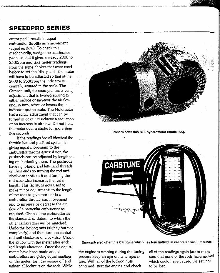
SPEEDPRO SERIES
erator pedal results in equal carburettor throttle arm movement (equal air flow). To check this mechanically, wedge the accelerator pedal so. that it gives a steady 2000 to 2500rpm and take meter readings from the same chokes that were used before to set the idle speed. The meter will have to be adjusted so that at the 2000 to 2500rpm the indicator is centrally situated in the scale. The Gunson unit, for example, has a vent adjustment that is twisted around to either reduce or increase the air flow and, in tum, raises or lowers the indicator on the scale. The Motometer has a screw adjustment that can be turned in or out to achieve a reduction or an increase in air flow. Do not hold the meter over a choke for more than five seconds.
If the readings are all identical the throttle bar and pushrod system is giving equal movement to the carburettor throttle ·arms: if not, the pushrods can be adjusted by lengthen-ing or shortening them. The pushrods have right-hand and left-hand threads on their ends so turning the rod anti-clockwise shortens it and turning the rod clockwise increases the rod's length. This facility is now used to make minor adjustments to the length of the rods to give more or less carburettor throttle arm movement and to increase or decrease the.air flow of a particular carburettor as required. Choose one carburettor as the standard, or datum, to which the other carburettors will be matched. Undo the locking nuts (slightly but not completely) and then turn the central rod anti-clockwise or clockwise. Check the airflow with the meter after each rod length alteration. Once the adjust-ments have been made and all carburettors are giving equal readings on the meter, turn the engine off and tighten all locknuts on the rods. While
Eurocarb offer this STE syncrometer (model SK).
Eurocarb also offer this Carbtune which has four individual calibrated vacuum tubes.
the engine is running during the tuning process keep an eye on its tempera-ture. With all of the locking nuts tightened, start the engine and check
all of the readings again just to make sure that none of the rods have moved which could have caused the settings to be lost.
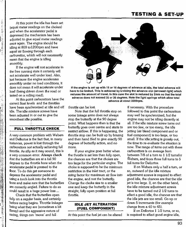
At this point the idle has been set (equal meter readings on the chokes) and when the accelerator pedal is depressed the mechanism has been adjusted to give equal meter readings once again. The engine should be idling at 800 to1200rpm and have equal air flowing through each carburettor, which will not necessarily mean that the engine is idling smoothly.
If the engine will not accelerate in the free running state it certainly will not accelerate well under load. Also, just because the engine accelerates smoothly under no load conditions, it does not mean it will accelerate under load (being driven down the road or tested on a rolling road).
At this point carburettors have the correct float levels and the throttles have been synchronized at idle and off idle. The idle mixture screws have been adjusted in or out to give the smoothest idle possible.
FULL THROTTLE CHECK
A very common problem with Webers and Dellortos is the fact that, in many instances, power is lost through the carburettors not actually achieving full throttle. As silly as it may sound, this is a very common error. Always check that the butterflies are at a full 90 degrees to the throttle bore when the accelerator pedal is pressed to the floor. To do this get someone to depress the accelerator pedal and using a torch look into the throttle bore and make sure that the butterflies are correctly angled. Failure to do so could result in a huge power loss ...
Check that the butterflies open fully on a regular basis, and certainly before racing begins. Throttle linkages being what they are (sometimes a bit flimsy) and the aggressive nature of racing, things can 'move' and full
TESTING & SET·UP
.
If the engine is set up with 15 or 16 degrees of advance at Idle, the total advance will have to be limited. This is achieved by braising the advance slot (arrowed right) which reduces the amount of travel. In this case the slot is reduced by 2mm so that the total
advance does not exceed 35 or 36 degrees. Note the light springs which allow·total advance at about 3300rpm.
throttle can be lost. Note that the full throttle stop on
some linkage arms does not always stop the butterfly at the 90 degree point. What happens then is that the butterfly goes over centre and starts to restrict airflow. If this is happening, the throttle stop can be built up by brazing and then hand filed to give exactly 90 degrees of butterfly action, and no more.
If your engine goes better when the throttle is set less than fully open, the chances are that the chokes are too large for the particular engine. The choke is supposed to be the minimum restriction in the inlet tract, or the sizing factor for maximum air flow into the engine, and not the butterfly. Change the choke size to a smaller one and keep the butterfly in the straight, fully open position at full throttle.
IDLE JET ALTERATION (FUEL COMPONENT)
At this point the fuel jet can be altered
if necessary. With the procedure followed to this point the carburettors may well be synchronised, but the engine may not be idling decently at all. If the idle mixture screw turns out are too few, or too many, the idle jetting (air bleed component and or fuel component) is too large, or too small. If the idle jetting is grossly out, the time to re-evaluate the situation is now. The range of turns out with these carburettors is on average from between 718 of a turn to 1 1/2 turnsfor Webers, and from three full turns to 5 full turns for Dellortos.
If on Webers only a half a turn, or so, outward of the idle mixture adjustment screws is required to effect good idle, the chances are that the idle jet is too large. If, on the other hand, the idle mixture adjustment screws have to be turned out 2 1/2 turns to effect a good idle, the chances are that the idle jets are too small. Go up or down 5 increments (for example change from a 40 to 45).
If on Dellortos 1 1/2 turns, or so, is required to effect good engine idle,
93
SPEEDPRO SERIES
the chances are that the idle jets are too large. If on the other hand at least 6 1/2 turns, or more, is required to effect good engine idle, the chances are that the idle jets are too small. Change the jet size up or down by 5 increments.
If an individual idle mixture adjustment screw does not respond to adjustment the chances are that there is a blockage somewhere in the passageway. If blowing through with~ compressed air fails to remove the obstacle the lead plug may have to be removed. All manner of obstructions
-- - ·have been found in carburettors (including bits of lead plugs!). Check that the idle mixture adjusting screw's taper is not bent, making adjustment near impossible.
IGNITION TIMING • GENERAL
At this point it mus~:be pointed out that your engine COJ;!ld be idling quite unevenly and be spitting back through the carburettors. This problem can be evident from all carburettor chokes consistently or at random or it may affect just one choke constantly. In the first instance, check the amount of spark advance at idling rpm with a strobe light. If the advance is 8 degrees BTDC this may well be the sole cause of the spitting back through the carburettors. The problem is, in fact, nothing to do with the carburettors or their settings, though the carburettors are often wrongly blamed for this common fault. Before any further adjustments are made to the carburettors, the ignition timing must be checked.
Modified engines nearly always need a considerable amount of initial spark advance. If the engine being tuned does not have sufficient idle speed advance it will be impossible to get good clean performance below
2700 to 3500rpm (depending on the camshaft) without resorting to very large idle jets and lots of turns out on the idle screws, after which the rich-ness of the mixture will tend to cover the lack of spark advance and reduce the spitting back but the engine will lack 'snap'. Low speed performance can be greatly improved, but the distributor advance mechanism will usually have to be altered to achieve this.
A reasonable idle speed for a modified engine is generally between 1000rpm and 1200rpm but some may require more rpm than this. If the engines rpm increases as advance is increased there is not enough advance built into the engine. At a 1200rpm idle speed the maximum amount of advance allowable would be on average about 16 degrees BTDC. Some engines like up to 18 degrees BTDC and some could stand even more, but getting the starter to turn the engine over can be a problem. Obvi-ously, the starter is the limiting factor in any given situation, but 16 degrees static advance is nearly always within the capability of the starter motor. If the engine runs best with 18 degrees static advance but the starter motor has trouble turning the engine over, retard the spark in one degree incre-ments until the starter will actually turn the engine over and start it.
If the engine performs well everywhere except at or near maxi-mum rpm (design strength maximum of the engine, that is) yet a misfire persists, check that the engine has enough spark advance. To test this, fit the carburettors with a small air corrector (160) and run the engine with two degrees more advance than before.
The following is an approximate guide to the maximum full advance degrees for a range of engines with a
various combustion chamber shapes (it is the combustion chamber shape that determines the optimum amount of total spark advance).
Bowl in piston: 3844 degrees BTDC. Hemi-head: 38-44 degrees BTDC. Bathtub head: 34-38 degrees BTDC. Pent roof (four valves per cylinder head): 30-32 degrees BTDC. Wedge head: 28-38 degrees BTDC.
The correct amount of idle advance for any given engine is found by setting the idle speed to 1000 to 1200rpm with the advance set at 12 degrees BTDC (the author has yet to see a modified engine that uses less than 12 degrees static advance). Then increase the advance by two degrees (using a strobe light) and note the engine rpm. If the engine rpm does not increase, the advance is correct. If the rpm increased with the two de-grees advance, advance the spark another two degrees to 16 degrees BTDC. Stop advancing the engine if the rpm does not increase. If the engine rpm increases to, say, 1700rpm by the time you have 16 degrees BTDC registering, reduce the idle speed back to 1200 via the carburettor idle screw.
Essentially, the final result should see the engine idling at the reasonable rate of about 1000 to 1200rpm with optimum spark advance so that it idles as smoothly as possible.
The downside of this increase in static advance is that, while the ad-vance has been increased from, say, 8 degrees static advance to 16 degrees, the total advance has also gone up. So what used to be 8 degrees static and 38 degrees total advance (via the automatic advance mechanism), for example, suddenly becomes 16 degrees static and 46 degrees total advance. This must be altered to 16
TESTING & SET-UP degrees static and 38 degrees total where it means that the engine has a amount of 'progression phase' air/fuel advance. The amount of total advance very smooth idle, a light sound to the mixture is set by the idle jetting and is required usually remains similar to exhaust (at idle) and an acceptable only adjustable by changing the jet standard even when an engine is idle speed CO reading (2.5-3% CO) sizes (air and fuel components). modified. should, in the overall scheme of The air/fuel mixture which is
This extra advance will have to be things, have very little to do with the supplied to the idle mixture adjusting removed from the distributor because, immediate off idle performance, or the screws and the progression holes is if left, it could lead to poor top end 'progression phase' as it is termed, of mixed by the idle jet and then travels performance and engine damage. The the engine. to the progression holes and on to the solution is to reduce the mechanical The immediate off idle response idle mixture adjusting screws in same advance mechanism's travel. This of an engine equipped with Webers or passageway. This is how closely these entails welding (tig welding or braising) Dellortos is controlled by the idle jets, items are linked to each other. the advance slot and remachining it. although the accelerator pumps do A noteworthy point is, of course, The slot will look the same but offer have some influence. If the engine is that the adjustment of the idle mixture less travel. Checking and testing after accelerated slowly the accelerator adjusting screws can, to a small welding is carried out using a strobe pumps have no effect,so checking the degree, be used to advantage for light. Basicaliy, the advance added to idle jets on the basis of richness/ tuning purposes on the basis of the initial timing must be remov~d leanness is based on this factor: the richening the 'progression phase' from the total timing. Note that some engine is accelerated slowly, but there mixture, but at the expense of the idle aftermarket distributors are adjustable must be no hesitation at all. One thing speed CO content and the absolute and can be altered in five minutes, an is for sure,. if the idle jets are too small, smoothness of the idle. example the being Mallory YL dual or too large, an engine will not Take, for example, an engine that point. accelerate cleanly at all. idles perfectly well when there is, say,
What happens in these 1 114 turns out of each idle mixture IDLE JETS/AIR BLEEDS • carburettors is that the idle jets feed adjustment screw (Weber carburettors
FIN,A_L SELECTION the idle mixture adjusting screws in this example) and idles well, and which, in tum, allow the engine its can be slowly accelerated cleanly
The next stage is to check the idle only source of air/fuel mixture when when not under load. All seems mixture strength requirements for the butterfly is set to a suitable idle perfect, yet, when that engine is good progression. The idle mixture speed (choke not operating, of subjected to load (as in the car being strength for idling purposes is not course). When the throttle is opened driven on the road or track), the really in question because it is the butterfly sweeps past the engine hesitates. The problem here is adjustable via the idle mixture progression holes which then become one of 'progression phase' mixture adjusting screw. The mixture strength downstream of the edge of the weaknessThe first thing to do is to for progression has to be correct over butterfly and, therefore, subject to see if the hesitation can be removed a band, whiCh means that the engine engine vacuum. In this situation air/ (without changing the idle jetting) by Will run quite acceptably anywhere fuel mixture from the idle jets is being increasing the amount of air/fuel Within this band. One side of the band admitted to the engine via the idle mixture that is constantly being will be towards the lean side and the mixture adjusting screws and the admitted to the engine via the idle other nearer the rich side. The progression holes. So, effectively, the mixture adjusting screws. This means objective of the fine tuning is to make idle jets are sized to the air/fuel increasing the idle screw turns out a sure that the mixture strength is in the requirements of the engine during the further 1/4 turn on a Weber and a 112 middle of the band because, not only progression phase and not the turn on a Dellorto. This will upset the Will the engine be as crisp as possible, requirements of the engine at idle as idle CO reading and, perhaps, the idle it will give the maximum economy the name of the jets involved might smoothness, but, often, the effect on Possible without any sacrifice in suggest. More important is the fact that these two factors is minimal and the Power. the idle mixture requirement of an 'progression phase' hesitation
The factor of turning the idle engine is adjustable via the idle disappears. What has happened in mixture adjusting screws to a position mixture adjusting screws, whereas the such cases is that little bit of extra idle
95
SPEEDPRO SERIES
mixture provided is enough to supply the engine with just enough air/fuel mixture to prevent the hesitation.
If the idle mixture CO setting goes too high then the size of the idle jetting needs to be altered, this may be as simple as reducing the size ofthe air bleed hole on a Weber or increasing the fuel jet size by 2 on a Dellorto. It frequently does not take much of an adjustment to remove 'acceleration phase' hesitation under load. A larg<> adjustment which causes a considerable increase in the air/fuel richness may well remove the 'acceleration phase' hesitation, but the 'progression phase' air/fuelmay now be very rich, which is wasteful of fuel and quite unnecessary. The air/fuel mixture needs to be rich enough, but no more. If every component of the jetting of a Weber or Dellorto is over-rich to cover problems, the result is exceedingly poor fuel economy. Whether the car is:used on the road or the race track, it might as well be adjusted correctly for best possible power and within reason, economy. On a road car equipped with Webers or Dellortos there is no joy in having to fill up with fuel at every second gas station/garage. This can become very wearing but, unless the time is taken to narrow down the range of possible adjustments, is often the result.
The use of an exhaust gas analyser which gives a direct reading can be of immense help in the sorting out of air/fuel mixture ratios. These often inexpensive machines can be hooked up to the engine's exhaust system and give you an exact reading within five minutes and remove all possible doubt as to whether the engine isrunning too rich or lean. On average, the CO reading will be between 2.5-3.5% CO. No engine should really need to be set with more than 3.5% CO; consider 2.5% CO as
96
the ideal and obtainable setting for a road going engine.
Weber In the first instance the idle mixture adjusting screws are set at the number of turns out which gives a 'good idle. ' Then, with the engine idling as smoothly as possible, very slowly increase the engine speed. The object of the exercise is to check if the mixture strength is sufficient to match the slowly opening throttie without there being any hesitation/missing/ stumble amnd without any assistance from the accelerator pump fuel delivery. If the engine stumbles/ hesitates, the mixture is too weak. If the idle mixture adjusting screws are set to, say, 1 114 turns to effect good idle, but the engine stumbles when slowly accelerated, turn the idle mixture adjusting to 1 3/4 of a turn out and try it again. If the engine still stumbles/hesitates, the jetting will have to be altered as it is unlikely that 'progression phase' acceleration is going to improve without the idle speed CO reading going well beyond 3.5%. So, if the engine stumbles/ hesitates, go to a richer combination (from, say, F2 to F11 but with the same prefix numbers - a jump richer by two). If the engine still stumbles, go to F9 and, finally, to F6. The idle mixture adjusting screws will need to be re-adjusted after any jet changing.
If none of these air bleed reduc-tions cure the problem go up in prefix numbers, for example, from 45 to 50 and start again with an F2 and work down in two stage increments (F2, F11, F9, F8, F6). If, for example, the jetting fitted to the engine was started at 45F2 and after proceeding down the range from there to 45Fll, 45F9, 45F8 and, finally, 45F6 and the stumble is still present, change the fuel jet number to 50F2 and proceed to go
through the range again 50Fll, 50F9 50F8 and 50F6. Repeat this procedur~ until a suitable combination is found.
The converse is also true that if the idle jet selected is too rich and there is no hesitation the mixture can be leaned off until the engine does hesitate. The mixture strength can then be made richer by jetting up until the hesitation ceases. An over-rich mixture does not give top perfor-mance.
The idle screws have remained untouched so far during this test. With a jet found that gives no hesitation, turn all idle mixture screws in a quarter turn and note any difference to the idle (smoother) then turn them back to where they were before and then tum them out a quarter turn and note any differences. The smoother the engine runs the better. All screws must be set to the same number of turns and part turns out. Remember to allow ten seconds once the last screw has been turned for the engine to settle and stabilize using the new mixture. Find the best position for the idle mixture adjusting screw for the smoothest idle possible (least exhaust pulsing as felt by hand at the end of the exhaust pipe).
By leaving the idle mixture screws in a set position and changing the jetting to suit, the richnessneanness factor is narrowed right down to the equivalent of about a quarter turn of the idle mixture screws; ideal for idling purposes and offering good progres-sion with the engine in the free revving state.
Under load, the setting may prove to be not quite rich enough. Just because the engine accelerates smoothly under no load conditions it does not mean it will accelerate cleanly under load (being driven down the road or tested on a rolling road). If this happens move richer again until the
hesitation stops under load conditions. The best test for a road vehicle is on an inclined section of road (not too steep) using top gear. If the engine mixture strength is too weak this sort of test will show it up. Jet up enough, but only enough, to provide for good progression. High speed is not neces-sary for this testing, rather low end pulling power.
If the idle jet (prefix number) is changed to overcome hesitation under load, the idle mixture will be richer and the idle mixture adjusting screws will have to be altered (turned in). This iS exactly what they are designed for; tum them in a half turn or whatever is necessary to restore idle smoothness or remove the 'heaviness' that a too rich mixture gives.
Dellorto Although Dellorto carburettors have a range of 10 idle jet holders, only the 7850.1, 7850.3, 7850.6, 7850.7, 7850.2 and 7850.8 (lean to rich) need to•be taken into consideration for performance applications. The 8750.1 idle jet holder is an ideal starting point.
Dellorto carburettors can be a little bit less complicated than Webers when it comes to selecting the correct idle jet. The reason for this is the reasonably widespread practice of fitting either 7850.2, 7850.6 or 7850.1 idle jet holders to all engines initially, and increasing the size of the idle jet until acceptable idle speed running and smooth progression phase performance obtained. This means that only the idle jetiirchangedto effect mixture corrections. This does not always prove to give optimum mixture strength, but frequently is very close; so close as to be acceptable. As With the Weber, what matters with idle jet selection is how well the engine accelerates from idle speed through the 'progression phase'.
What happens is that the air/fuel mixture that goes to the progression holes and the idle adjustment screw is supplied by the same jet: the idle jet and its air bleed component. The major difference in dealing with the two factors is that the idle mixture is adjustable via the idle mixture adjustment screws. The progression phase air/fuel mixture is not adjustable, other than by changing jets. Invariably, if the jetting is suitable for the progression phase of the engine, the idle mixture adjusting screws can be adjusted to suit and allow the engine to idle perfectly. If the idle jets are not correct for the acceleration phase, they may well be suitable for perfect idle. So, it's quite possible to fit jets to an engine and get it idling perfectly by adjusting the mixture screws, only to find that once the throttle is opened the engine will not go through the 'progression phase' because the jets are too lean.
If this happens, the idle jet size (fuel component) must be increased, such as going from a 45 to 50. With the Dellorto, it's possible to increase, or decrease for that matter, the jetting by 1 or 2 sizes at a time until the richness factor is correct. If the jetting is suspected to be too rich for the progression phase, reduce the jet size by 1 or 2 sizes and try again. Adjust the idle mixture adjusting screw at each jet change just to make sure that the idle mixture is actually at 2% to 2.5% CO (an acceptable air/fuel mixture).
For Dellortos the range of air bleed and fuel jet combinations is vast, and five times that of Weber. In the interests of cost and overall efficiency, however, the range can be narrowed down by using just five idle jet holders (lean to rich): 7850.1, 7850.6, 7850.7, 7850.2 and 7850.8. The 7850.3 size falls between the 7850.6
TESTING & SET-UP
and the 7850.2, and isn't really worth having over the other two.
The first step is to fit the fuel jet suggested in chapter 4 to a 7850.1, 7850.6 or 7850.2 idle jet holder and, with the idle mixture adjusting screws set to the number of turns that effects best idle, check the 'progression phase' by very slowly increasing the engine rpm (no higher than 2500rpm).
If the engine stumbles/hesitates, turn the idle mixture adjusting screws out a further 1/2 turn and try again. If the engine still stumbles/hesitates, turn the idle mixture adjusting screws out to a maximum of 5 1/2 full turns from the lightly seated position. If the engine still stumbles/hesitates, the fuel jet size will have to be increased until the hesitation disappears. A jet size change will mean resetting the idle mixture adjustment screws to give the smoothest idle. Using an exhaust gas analyser is recommended in the interests of getting the air/fuel mixture right at idle and through the 'progression phase.'
The 7850.1 idle jet holder has a 1.4mm diameter hole in the side of the idle jet holder and an axial bore diameter of 3.0mm. Any engine that has 400cc per cylinder and above will usually use this idle jet holder. The amount of air bleed from a 7850.1 is act>Ially very similar to an F2 from the Weber range and the F2 is only a middle of the range air bleed (when applied to richness and leanness capabilities with a given fuel jet).
If there is no hesitation with the recommended idle jet leave the jetting just as it is and see how the engine performs under road or track condi-tions. The fuel jet size may prove to be too large but this is not likely. The idle jets recommended tend toward leanriess so, if anything, will require increasing in jet size to overcome obvious leanness (hesitation during the
97
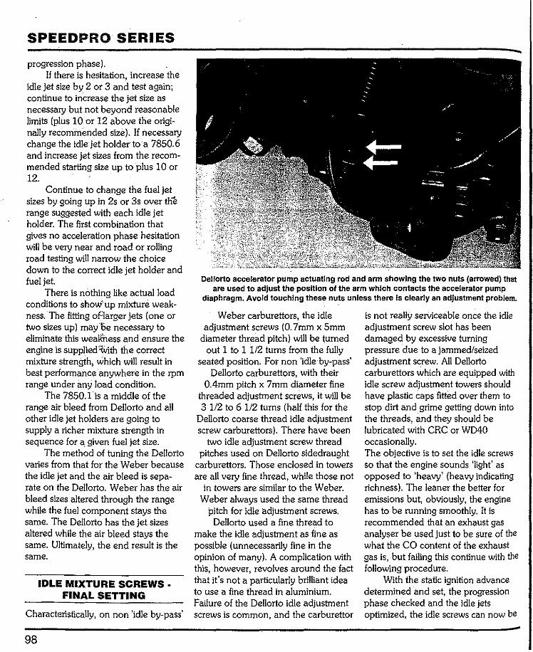
SPEEDPRO SERIES
progression phase). If there is hesitation, increase the
idle jet size by 2 or 3 and test again; continue to increase the jet size as necessary but not beyond reasonable limits (plus 10 or 12 above the origi-nally recommended size). If necessary change the idle jet holder to a 7850.6 and increase jet sizes from the recom-mended starting size up to plus 10 or 12.
Continue to change the fuel jet sizes by going up in 2s or 3s over the range suggested with each idle jet holder. The first combination that gives no acceleration phase hesitation will be very near and road or rolling road testing will narrow the choice down to the correct idle jet holder and fuel jet
There is nothing like actual load conditions to show' up mixture weak-ness. The fitting of-larger jets (one or two sizes up) mayoe necessary to eliminate this weaK'ness and ensure the engine is supplied with the correct mixture strength, which will result in best performance anywhere in the rpm range under any load condition.
The 7850.lis a middle of the range air bleed from Dellorto and all other idle jet holders are going to supply a richer mixture strength in sequence for a given fuel jet size.
The method of tuning the Dellorto varies from that for the Weber because the idle jet and the air bleed is sepa-rate on the Dellorto. Weber has the air bleed sizes altered through the range while the fuel component stays the same. The Dellorto has the jet sizes altered while the air bleed stays the same. Ultimately, the end result is the same.
IDLE MIXTURE SCREWS • FINAL SETTING
Characteristically, on non 'idle by-pass'
98
Dellorto accelerator pump actuating rod and arm showing the two nuts (arrowed) that are used to adjust the position of the arm which contacts the accelerator pump
diaphragm. Avoid touching these nuts unless there is clearly an adjustment problem.
Weber carburettors, the idle adjustment screws (0. 7mm x 5mm
diameter thread pitch) will be turned out 1 to 1 1/2 turns from the fully
seated position. For non 'idle by-pass' Dellorto carburettors, with their
0.4mm pitch x 7mm diameter fine threaded adjustment screws, it will be 3 1/2 to 6 1/2 turns (half this for the
Dellorto coarse thread idle adjustment screw carburettors). There have been
two idle adjustment screw thread pitches used on Dellorto sidedraught
carburettors. Those enclosed in towers are all very fine thread, while those not
in towers are similar to the Weber. Weber always used the same thread
pitch for iclle adjustment screws. Dellorto used a fine thread to
make the idle adjustment as fine as possible (unnecessarily fine in the opinion of many). A complication with this, however, revolves around the fact that it's not a particularly brilliant idea to use a fine thread in aluminium. Failure of the Dellorto idle adjustment screws is common, and the carburettor
is not really serviceable once the idle adjustment screw slot has been damaged by excessive turning pressure due to a jammed/seized adjustment screw. All Del!orto carburettors which are equipped with idle screw adjustment towers should have plastic caps fitted over them to stop dirt and grime getting down into the threads, and they should be lubricated with CRC or WD40 occasionally. The objective is to set the idle screws so that the engine sounds 'light' as opposed to 'heavy' (heavy indicating richness). The leaner the better for emissions but, obviously, the engine has to be running smoothly. It is recommended that an exhaust gas analyser be used just to be sure of the what the CO content of the exhaust gas is, but failing this continue with the following procedure.
With the static ignition advance determined and set, the progression phase checked and the idle jets optimized, the idle screws can now be
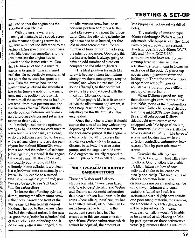
adjusted so that the engine has the smoothest possible idle.
With the engine warm and running at a suitable idle speed, screw all the mixture adjusting screws in a half turn and note the difference to the engine's idling speed and smoothness. If the idle becomes smoother and the rpm increases the engine has re-sponded to the leaner mixture. Con-tinue to turn all of the idle mixture screws in (a quarter turn at a time) until the idle perceptively roughens. At this point the mixture has gone too lean. Turn the screws back to the position that produced the smoothest idle so far (make a note of how many turns out this position represents). Now turn all the screws out (a half turn at a time) from that position until the idle becomes 'heavy.' Work out the middle position between over-weak-ness and over-richness and set all the screws to that position.
It is fairly usual for the optimum setting to be the same for each mixture screw but this is not always the case, so do the following test. Go to the end of the exhaust pipe and place the palm of your hand about 50mm/2in away from it and feel the individual exhaust pulses against your hand. If the engine has a wild camshaft, the engine may idle roughly but it should still idle uniformly. If one cylinder is a bit lean, that cylinder will miss occasionally and this will be noticeable as a missed exhaust pulse against your hand; you may also be able to see 'spit back' from the carburettor/s.
To locate the offending cylinder, start by turning the idle mixture screw of the choke nearest the front of the engine one full turn from its current Position. Then go to the exhaust pipe and feel the exhaust pulses. If the miss has gone the cylinder (or cylinders) fed by this choke is the offending one. If the exhaust pulse is unchanged, turn
the idle mixture screw back to its previous position and move to the next idle screw and repeat the proce-dure. Once the offending cylinder (or cylinders) has been located, set that idle mixture screw out a sufficient number of turns or part turns to stop the miss, but no more. Obviously this particular cylinder is always going to have an odd number of turns out compared to the other cylinders.
The ideal position for each idle screw is between when the mixture strength weakens perceptively (engine misses) and when it turns rich (idle sounds 'heavy'), or that point that gives the highest idle speed with the maximum idle smoothness.
When engine idle is at its smooth-est via the idle mixture adjustment, if necessary, reset the idle rpm by adjusting the throttle arm (slow the engine down).
Once the engine is warm it should start at the turn of the key without any depressing of the throttle to activate the accelerator pumps. If the engine is a bit reluctantto start, depress the accelerator pedal quickly to quarter distance to activate the accelerator pumps and the engine should start. Cold engines will usually respond to one full pump of the accelerator peda.
'IDLE BY·PASS' CIRCUITRY CARBURETTORS
There are Weber and Dellorto carburettors which have been fitted with 'idle by-pass' circuitry and Welier and Dellorto sidedraught carburettors that have not been fitted with it. In the cases where 'idle by-pass' circuitry has been fitted virtually all of them can be made in-operative by turning the adjustment screws fully in. The exception to this are some emission type 40mm Weber carburettors which cannot be adjusted, the amount of
TESTING & SET·UP
'idle by-pass' is factory set via drilled holes.
The majority of emission type 40mm sidedraught Webers all had adjustable 'idle by-pass' circuitry fitted (with recessed adjustment screws). The later Spanish built 40mm DCOE 151 and 45mm DCOE 152 carburettors also have idle by-pass' circuitry fitted to them, with the adjustment screws in cast in towers on each side of the body. A plastic cap covers each adjustment screw and locking nut. That's the same principle of operation for both types of adjustable carburettor but a different method of achieving it.
When Dellorto started making their sidedraught carburettors in the late 1960s, none of their carburettors were fitted with 'idle by-pass' circuitry but in the mid-1970s they changed this and all subsequent Dellorto sidedraught carburettors came equipped with 'idle by-pass' circuitry. The 'universal performance' Dellortos have external adjustment 'idle by-pass' screws and locking nuts while the emission controlled carburettors have recessed 'idle by-pass' adjustment screws.
Consider the 'idle by-pass' circuitry to be a tuning tool with a few functions. One function is to enable tlfe idle mixture air flow of each individual choke to be leaned off quickly and easily. This means that all chokes, no matter how many carburettors are on an engine, can be set to have minimum and equal emissions (equal air flow). If a carburettor has a slightly bent spindle or a poor fitting butterfly, for example, the air content for each cylinder can still be adjusted via this means, whereas normally it wouldn't be able to be adjusted at all. Having an 'idle by-pass' system on these carburettors virtually guarantees that the minimum
99
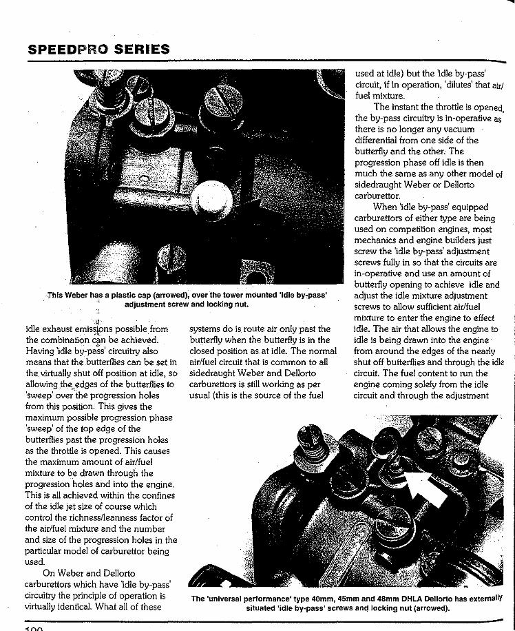
SPEEDPRO SERIES used at idle) but the 'idle by-pass' circuit, if in operation, 'dilutes' that air/ fuel mixture.
The instant the throttle is opened the by-pass circuitry is in-operative as' there is no longer any vacuum differential from one side of the butterfly and the other. The progression phase off idle is then much the same as any other model of sidedraught Weber or Dellorto carburettor.
·This Weber has a plastic cap (arrowed), over the tower mounted 'idle by-pass'
When 'idle by-pass' equipped carburettors of either type are being used on competition engines, most mechanics and engine builders just screw the 'idle by-pass' adjustment screws fully in so that the circuits are in-operative and use an amount of butterfly opening to achieve idle and adjust the idle mixture adjustment screws to allow sufficient air/fuel mixture to enter the engine to effect idle. The air that allows the engine to idle is being drawn into the engine from around the edges of the nearly shut off butterflies and through the idle circuit. The fuel content to run the engine coming solely from the idle circuit and through the adjustment
adjustment screw and locking nut.
idle exhaust emissionspossible from the combination can be achiev~d. Having 'idle by-pa~s' circuitry also means that the butterflies can be set in the. virtually shut off position at idle, so allowing Jhe.edges of the butterflies to 'sweep' ove;·the progression holes from this position. This gives the maximum possible progression phase 'sweep' of the top edge of the butterflies past the progression holes as the throttle is opened. This causes the maximum amount of air/fuel mixture to be drawn through the progression holes and into the engine. This is all achieved within the confines of the idle jet size of course which control the richness/leanness factor of the air/fuel mixture and the number and size of the progression holes in the particular model of carburettor being used.
On Weber and Dellorto carburettors which have 'idle by-pass' circuitry the principle of operation is virtually identical. What all of these
systems do is route air only past the butterfly when the butterfly is in the closed position as. at idle. The normal air/fuel circuit that is common to all sidedraught Weber and Dellorto carburettors is still working as per usual (this is the source of the fuel
The 'universal performance' type 40mm, 45mm and 48mm DHLA Dellorto has externallY situated 'idle by-pass' screws anQ locking nut (arrowed).
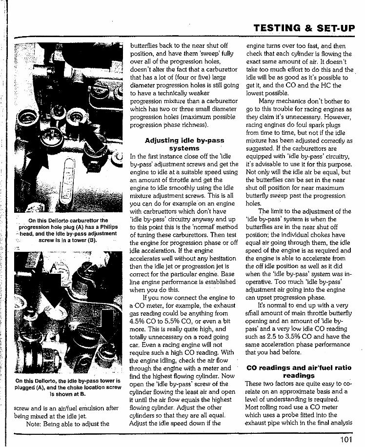
·On this Dellorto carburettor the ·progression hole plug (A) has a Philips ···head, and the Idle by-pass adjustment
screw Is in a tower (B).
On this Dellorto, the Idle by-pass tower Is plugged (A), and the choke location screw
is shown at B.
screw and is an air/fuel emulsion after being mixed at the idle jet
Note: Being able to adjust the
butterflies back to the near shut off position, and have them 'sweep' fully over all of the progression holes, doesn't alter the fact that a carburettor that has a lot of (four or five) large diameter progression holes is still going to have a technically weaker progression mixture than a carburettor which has two or three small diameter progression holes (maximum possible progression phase richness).
Adjusting idle by-pass systems
In the first instance close off the 'idle by-pass' adjustment screws and get the engine to idle at a suitable speed using an amount of throttle and get the engine to idle smoothly using the idle mixture adjustment screws. This is all you can do for example on an engine with carbruettors which don't have 'idle by-pass' circuitry anyway and up to this point this is the 'normal' method of tuning these carburettors. Then test the engine for progression phase or off idle acceleration. If the engine accelerates well without any hesitation then the idle jet or progression jet is correct for the particular engine. Base line engine performance is established when you do this.
If you now connect the engine to a CO meter, for example, the exhaust gas reading could be anything from 4.5% CO to 5.5% CO, or even a bit more. This is really quite high, and totally unnecessary on a road going car. Even a racing engine will not require such a high CO reading. With the engine idling, check the air flow through the engine with a meter and find the highest flowing cylinder. Now open the 'idle by-pass' screw of the cylinder flowing the least air and open it until the air flow equals the highest flowing cylinder. Adjust the other cylinders so that they are all equaL Adjust the idle speed down if the
TESTING & SET-UP
engine turns over too fast, and then check that each cylinder is flowing the exact same amount of air. It doesn't take too much effort to do this and the idle will be as good as it's possible to get it, and the CO and the HC the lowest possible.
Many mechanics don't bother to go to this trouble for racing engines as they claim it's unnecessary. However, racing engines do foul spark plugs from time to time, but not if the idle mixture has been adjusted correctly as suggested. If the carburettors are equipped with 'idle by-pass' circuitry, it's advisable to use it for this purpose. Not only will the idle air be equal, but the butterflies can be set in the near shut off position for near maximum butterfly sweep past the progression holes.
The limit to the adjustment of the 'idle by-pass' system is when the butterflies a.re in the near shut off position; the individual chokes have equal air going through them, the Idle speed of the engine is as required and the engine is able to accelerate from the off idle position as well as it did when the 'idle by-pass' system was in-operative. Too much 'idle by-pass' adjustment air going into the engine can upset progression phase.
It's normal to end up with a very small amount of main throttle butterfly opening and an amount of 'idle by-pass' and a very low idle CO reading such as 2.5 to 3.5% CO and have the same acceleration phase performance that you had before.
CO readings and air'fuel ratio readings
These two factors are quite easy to co-relate on an approximate basis and a level of understanding is required. Most rolling road use a CO meter which uses a probe fitted into the exhaust pipe which in the final analysis
101
SPEEDPRO SERIES
is shown a a CO percentage reading on a dial by a needle or as a digital reading. The chemically correct air/fuel mixture ratio for best possible efficient burning is approximately 14.7 to 1 (that's 14.7 parts of air to 1 part of fuel) and the CO (carbon monoxide) eqivalent reading for this is 1% CO. Cars on the market today which comply with the California Air Resource Board's requirements run at an approximate 14.7 to 1 air/fuel ratio on a constant basis. The approximate equivalent CO to air/fuel ratios are listed below.
0. 9% CO or 14.7 to 1 air/fuel ratio 1. 0% CO or 14.3 to 1 air/fuel ratio 1.5% CO or 14.0 to 1 air/fuel ratio 2.0% CO or 13.7 to 1 air/fuel ratio 2.5% CO or 13.3 to 1 air/fuel ratio 3.0% CO or 13.1 to 1 air/fuel ratio 3.5% CO or 12.8 to1 air/fuel ratio 4.0% CO or 12.5 to 1 air/fuel ratio 4.5% CO or 12.2 to1 air/fuel ratio 5.0% CO .or 12.0 to 1 air/fuel ratio 5.5% CO or 11.6 to 1 air/fuel ratio 6. 0% CO or 11.3 to 1 air/fuel ratio
Consider a 2% CO reading possible with an engine which has carburettors equipped with 'idle by-pass' circuitry, a 2.5% to 3.5% CO reading possible with an engine which does not have carburettors fitted to it with 'idle by-pass' circuitry, including racing engines which can almost always be set to idle at least 3.5% CO. A full power mixture setting is one that on average has a 5.0% CO reading as a general requirement with some engines requiring a richer 5.5% to 6. 0% CO mixture setting.
Note that the 'California Air Resource Board' has been driving the world's auto manufacturers along the path of cleaner burning engines since about 1970. While working within the realms of the technology of the day
they have never the less been relentlessly getting the various engine manufacturers to reduce emissions.
ACCELERATOR PUMP JETS· FINAL SELECTION
The fixed jetting of the carburettor cannot respond quickly when the throttle is opened rapidly. The accelerator pump supplies fuel immediately and in sufficient volume to match the amount of air available to the engine when the throttle is opened quickly. Because the fuel injected by the accelerator pumps is not emulsified, more than is strictly necessary is injected into the air stream and much of it is passed out of the engine unburnt.
Once the main circuit comes into operation and the auxiliary venturi is flowing air/fuel mixture, the accelerator pump is no longer needed. If the engine emits a lot of black smoke when the throttle is suddenly opened this is a sign that the accelerator pump jets are too large. However, the next size down in pump jets (for Weber) may well cause the engine to hesitate. On Dellortos the larger range of jet sizes allows for very fine adjustment.
Fit the accelerator pump jet that is the smallest possible compatible with the engine having good acceleration without any hesitation. Try the recom-mended pump jet and increase the jet size if it proves to be insufficient. Conversely, try the next size down from the recommended size just to see if the engine can operate with that size. If the test proves successful, change down a size.
If the engine hesitates irrespective of the pump jet size installed in the carburettor, check the timing of the fuel delivery from the accelerator pump discharge nozzles compared to the throttle movement. This action has
to be simultaneous. On Dellortos check that the arm
that operates the diaphragm is in fact in contact with the diaphragm base. These arms are factory set and usually correct but if the carburettor is second-hand they may have been altered. If during quick throttle movement no fuel is ejected, the arm may well be moving but not moving the dia-phragm. The two locking nuts will have to be re-adjusted to take out the play that exists so that the diaphragm is activated immediately the throttle arm is moved. Note that it is possible to set the accelerator pump arm too high. If the nuts are wound up too far on the available thread, the arm can jam. If there is more than 0.3in/8mm of thread showing under the nut, it's undoubtedly too much.
When Weber or Dellorto carburettors are full of fuel they will squirt fuel well over 3 feet/1 meter when the throttle is opened quickly. If there is any doubt about accelerator pump effectiveness, remove the .carburettors from the engine (making sure that no fuel is spilled from them) and set them up level on a bench. To check the pump action depress the throttle about 20 per cent very quickly. Each nozzle should squirt fuel out of the choke and onto the bench and there should be a puddle of fuel in the throttle bore. There is a limited num-ber of times that this can be done as the float.chamber will empty itself. Pump action has to be instantaneous for correct engine acceleration. The quantity of fuel is correct when one full throttle arrn depression sends two long streams of fuel out of the carburettor immediately and for a full one second duration. Warning! Take appropriate fire precautions when testing accelerator pump action and protect your eyes and skin too.

,
l Chapter?
Testing & problem
The ultimate test of any· engine is how well it goes in its particular application. Competition brings outthe best in engines and the worst in faults. That is because of the conditions and stresses and strains that the machinery is being subjected to. For example, hundreds of cars are taken to the track each weekend and they are driven around lap after lap misfiring and backfiring. The drivers invariably are mystified at the antics of the engine: after all, they drove the car to the track and all was well. Bonnets are up and, usually, the carburettors are being scrutinized even though they are probably not to blame.
The real problem is usually one of preparation. Track conditions always show how well the work on the engine has been done. Sometimes, what should be really good engines have been run for years with what is, eventually, proved to be quite minor tuning problems.
For an engine to give top perfor-
solving
mance, every component must be proved to be in a serviceable condi-tion. That goes for new parts too: never assume that because a part is new that it's good. Even top quality parts can be proved faulty by the stress of competition work but these same parts could be put into a stan-dard road-going car and operate perfectly. The conditions in competi-tion are just not the same. Problems often stem from spark plugs. Plugs used on a road-going car have no place on an engine being raced. Take a perfect set of plugs with you and fit them at the track but only when the engine is going to be subjected to high rpm (no idling and so on). Remove them from the engine when the racing is finished and pack them away until next time. Note: if a spark plug is dropped to the ground don't use it in a racing engine again.
During testing and final adjust-ments, the question of choke sizes may arise, particularly whether there
might be any power benefit derived from fitting bigger chokes. By all means increase (or decrease) the size of the chokes by lmm at a time; however, it's unlikely that deviations of over 2mm from the recommendations given in chapter 4 will prove success-ful. Note, too, that if choke size is altered, the main jet/air corrector combination and idle jet will have to be rechecked in the original sequence and may need to be altered (richness/ leanness factor). Chokes that are too large for the application will not allow the engine to accelerate as well as it would with smaller chokes, even though the maximum power output will be similar. Chokes that are too small will limit maximum rpm quite sharply. Taking the trouble to make sure that exactly the right sized chokes are fitted to any engine, that is the smallest that allow the engine to develop maximum power, pays off in no uncertain terms.
103
SPEEDPRO SERIES
ROLLING ROAD (DYNO} TESTING PROCEDURE
Rolling roads are only as good as the person operating the machine and making the adjustments to the engine. True, the machine tells the operator what is happening (power loss or power gain) but that still leaves the decision on what is to be changed and so on to obtain optimum engine performance. The advantage of the rolling road is, of course, that any vehicle can be tested in a workshop environment with scientific apparatus connected to the engine while simulating road going conditions. The testing can be done more quickly and the changes made more quickly as all parts are readily at hand.
The rolling road simulates road conditions and there is no doubt that, in the hands of a good operator, the engine can be perfectlytuned by this means. There is no.;guesswork, asin, "did it go better this wayor that way?" Readings can be taken and even if the machine is a little bit out in calibration it doesn't matter too much because the machine will b.e out by a consistent amount. The consistency of the readings is all important and the rolling road's main asset. The rolling road, as the name suggests, is as near to a normal road as is possible. When using a rolling road, use a fan in front of the radiator, keep checking the water temperature and tie the car down!
The tendency with the rolling road is to run the engine up to full revs and take a power reading. Maximum power is useful to know as a check on whether the engine has come up to specification or expectations, but there is more to it than this. The objective should be an engine which performs strongly from off idle through to maximum rpm.
The best way to test the top end
104
performance of the engine is to run it in top gear from just above the power band rpm through to maximum rpm and measure the time taken to get from, say, 3500rpm to 7000rpm. If the engine is not 'crisp" it will be heard and the time taken· to get from 3500rpm to 7000rpm will be exces-sive. The initial test times can be used as a baseline figure and all future adjustments measured against them.
Most workshops with rolling roads also have electronic tune-up equip-ment and this should be connected to the engine just to check the integrity of the electrical system. Use every scientific aid available to you in the quest to get an engine tuned correctly.
TRACK TESTING PROCEDURE
The ultimate test of any tune-up is how well the engine runs on the road or track. But what goes well on the road may not go well on the track. This is because on the race track the engine will be operating from mid-range up to maximum rpm. All sorts of things happen in a track environment that will seldom happen elsewhere. For example, insufficient fuel pressure or volume will cause the engine to miss as the fuel level in the carburettors falls. The high load and sustained high rpm of track life will show up problems that would not be encountered on the road. Another example is that pulling out of turns using full throttle can make an engine hesitate and misfire, yet before the vehicle was tried on the track it was perfect. What all this means is that carburettor set-up may have to be altered to compensate for the demands of full bore track work. Luckily Dellorto and Weber carburettors are totally adjustable for all conditions and applications. However, they can only be made to
suit one application at a time! When track testing, use top gear
to check the top end performance and this is achieved by running the car over a set distance using top gear only. If the engine has a maximum rpm of 7000 and is on the power band (camshaft working) at, say, 3300rpm check acceleration over two set points. When the first set point (flag on a stick at the side of the track) is reached the engine must be at 3500rpm and in top gear. At the set point depress the accelerator to the floor and leave it there until the second set point (an-other flag on a stick at the side of the track) is reached. At the second set point note the rpm. If at the first trial the rpm was 6600rpm this is the datum against which all future adjust-ments are measured. The second set point can be moved (if space allows) so that the engine just makes maxi-mum rpm. Also from the first set point a stop watch should be used to check the time taken to get from the first set point to the second set point. Note the rpm and the times. Make only one engine adjustment or change at a time and measure the value of each change by the rpm and the time taken over the test distance.
When testing such as this is carried out, the engine is under the highest load possible and the rpm range is more than would usually be used. If the engine is going to falter it will do so under these conditions. There are no gearchanges to make (they could interfere with the consis-tency of the results) and the flexibility of the engine is fully tested.
SOLVING PROBLEMS· LOW TO MID-RANGE RPM
If the main jet is too small the engine will not produce good power anywhere in the range. An excessively
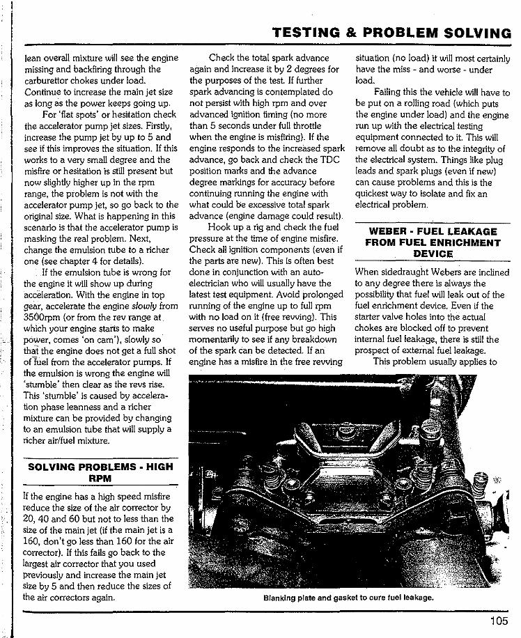
lean overall mixture wUI see the engine missing and backfiring through the carburettor chokes under load. Continue to increase the main jet size as long as the power keeps going up.
For 'flat spots' or hesitation check the accelerator pump jet sizes. Firstly, increase the pump jet by up to 5 and see if this improves the situation. If this works to a very small degree and the misfire or hesitation is still present but now slightly higher up in the rpm range, the problem is not with the accelerator pump jet, so go back to the original size. What is happening in this scenario is that the accelerator pump is masking the real problem. Next, change the emulsion tube to a richer one (see chapter 4 for details).
If the emulsion tube is wrong for the engine it will show up during acceleration. With the engine in top gear, accelerate the engine slowly from 3500rpm (or from the rev range at which your engine staris to make pOWer, comes 'on cam'), slowly so thai the engine does not get a full shot ofTuel from the accelerator pumps. If the emulsion is wrong the engine will 'stumble' then clear as the revs rise. This 'stumble' is caused by accelera-tion phase leanness and a richer mixture can be provided by changing to an emulsion tube that will supply a richer air/fuel mixture.
SOLVING PROBLEMS • HIGH RPM
If the engine has a high speed misfire reduce the size of the air corrector by 20, 40 and 60 but not to less than the size of the main jet (if the main jet is a 160, don't go less than 160 for the air corrector). If this fails go back to the largest air corrector that you used previously and increase the main jet size by 5 and then reduce the sizes of the air correctors again.
TESTING & PROBLEM SOLVING
Check the total spark advance again and increase it by 2 degrees for the purposes of the test. If further spark advancing is contemplated do not persist with high rpm and over advanced ignition timing (no more than 5 seconds under full throttle when the engine is misfiring). If the engine responds to the increased spark advance, go back and check the TDC position marks and the advance degree markings for accuracy before continuing running the engine with what could be excessive total spark advance (engine damage could result).
Hook up a rig and check the fuel pressure at the time of engine misfire. Check all ignition components (even if the paris are new). This is often best done in conjunction with an auto-electrician who will usually have the latest test equipment. Avoid prolonged running of the engine up to full rpm with no load on it (free rewing). This serves no useful purpose but go high momentarily to see if any breakdown of the spark can be detected. If an engine has a misfire in the free revving
situation (no load) it will most certainly have the miss - and worse - under load.
Failing this the vehicle will have to be put on a rolling road (which puts the engine under load) and the engine run up with the electrical testing equipment connected to it. This will remove all doubt as to the integrity of the electrical system. Things like plug leads and spark plugs (even if new) can cause problems and this is the quickest way to isolate and fix an electrical problem.
WEBER·FUELLEAKAGE FROM FUEL ENRICHMENT
DEVICE
When sidedraught Webers are inclined to any degree there is always the possibility that fuel will leak out of the fuel enrichment device. Even if the starter valve holes into the actual chokes are blocked off to prevent internal fuel leakage, there is still the prospect of external fuel leakage.
This problem usually applies to
Blanking plate and gasket to cure fuel leakage.
105
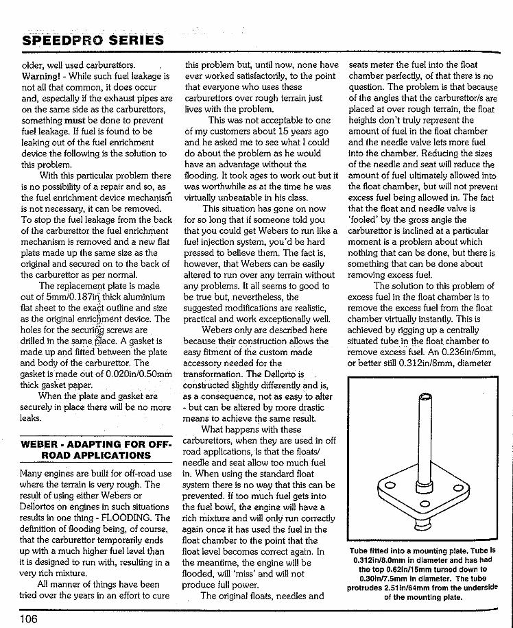
SPEEDPRO SERIES older, well used carburettors. Warning! -While such fuel leakage is not all that common, it does occur and, especially if the exhaust pipes are on the same side as the carburettors, something must be done to prevent fuel leakage. If fuel is found to be leaking out of the fuel enrichment device the following is the solution to this problem.
With this particular problem there is no possibility of a repair and so, as the fuel enrichment device mechanism is not necessary, it can be removed. To stop the fuel leakage from the back of the carburettor the fuel enrichment mechanism is removed and a new flat plate made up the same size as the original and secured on to the back of the carburettor as per normal.
The replacemel)t plate is made out of 5mmi0.187il): thick aluminium flat sheet to the exa£t outline and size as the original enrichmentdevice. The holes for the securiri:£ screws are drilled in the same place. A gasket is made up and fitted between.the plate and body of the carburettor. The gasket is made out of 0.020in/0.50mm thick gasket paper.
When the plate and gasket are securely in place there will be no more leaks.
WEBER ADAPTING. FOR OFF· ROAD APPLICATIONS
Many engines are built for off-road use where the terrain is very rough. The result of using either Webers or Dellortos on engines in such situations results in one thing- FLOODING. The definition of flooding being, of course, that the carburettor temporarily ends up with a much higher fuel level than it is designed to run with, resulting in a very rich mixture.
All manner of things have been tried over the years in an effort to cure
106
this problem but, until now, none have ever worked satisfactorily, to the point that everyone who uses these carburettors over rough terrain just lives with the problem.
This was not acceptable to one of my customers about 15 years ago and he asked me to see what I could do about the problem as he would have an advantage without the flooding. It took ages to work out but it was worthwhile as at the time he was virtually unbeatable in his class.
This situation has gone on now for so long that if someone told you that you could get Webers to run like a fuel injection system, you'd be hard pressed to believe them. The fact is, however, that Webers can be easily altered to run over any terrain without any problems. It all seems to good to be true but, nevertheless, the suggested modifications are realistic, practical and work exceptionally well.
Webers only are described here because their construction allows the easy fitment of the custom made accessory needed for the transformation. The Dellorto is constructed slightly differently and is, as a consequence, not as easy to alter - but can be altered by more drastic means to achieve the same result.
What happens with these carburettors, when they are used in off road applications, is that the floats/ needle and seat allow too much fuel in. When using the standard float system there is no way that this can be prevented. If too much fuel gets into the fuel bowl, the engine will have a rich mixture and will only run correctly again once it has used the fuel in the float chamber to the point that the float level becomes correct again. In the meantime, the engine will be flooded, will 'miss' and will not produce full power.
The original floats, needles and
seats meter the fuel into the float chamber perfectly, of that there is no question. The problem is that because of the angles that the carburettor/s are placed at over rough terrain, the float heights don't truly represent the amount of fuel in the float chamber and the needle valve lets more fuel into the chamber. Reducing the sizes of the needle and seat will reduce the amount of fuel ultimately allowed into the float chamber, but will not prevent excess fuel being allowed in. The fact that the float and needle valve is 'fooled' by the gross angle the carburettor is inclined at a particular moment is a problem about which nothing that can be done, but there is something that can be done about removing excess fuel.
The solution to this problem of excess fuel in the float chamber is to remove the excess fuel from the float chamber virtually instantly. This is achieved by rigging up a centrally situated tube in the float chamber to remove excess fuel. An 0.236in/6mm, or better still 0.312in/8mm, diameter
Tube fitted Into a mounting plate. Tube Is 0.312in/8.0mm in diameter and has had
the top 0.62in/15mm turned down to 0.30in/7.5mm In diameter. The tube
protrudes 2.511n/64mm from the underside of the mounting plate.

TESTING & PROBLEM SOLVING
Above- fuel drain installation. Below- Schematic of full s.cavenging system showing how excess fuel is pumped back to the fuel tank.
FUEL TANK
ELECTRIC FUEL PUMP
metal tube is fitted in the main jet tower of the carburettor. The top 0.62in/15mm of the tube needs to be turned down to 0.30in/7.5mm to clear internal casting shape. The top of the tube will be level with the surface level of the fuel in the float chamber when the carburettor is on level ground. This means that the top of the tube must be 2.5lin/64rnm above the mounting plate. The inside diameter of the tube needs to be a minimum of 0.187in/ Smm to a maximum of 0.236in/6mm for tube sizes suggested.
The original bottom well cover is replaced with a similar shaped piece of 0.312in/8mm thick aluminium which has the thin walled tube fitted into it. The end result is a drain positioned in the centre of the carburettor's fuel bowl. When the fuel level rises too high, the excess is immediately sucked away and returned to the fuel tank.
If the fuel tank is lower than the carburettors the fuel could self-drain out of the carburettor float chambers and back into the fuel tank, but off-road machines almost always have the fuel tank higher than the carburettors. Therefore, to scavenge the excess fuel, a small capacity Face! electric fuel pump, or similar, is used. The fuel pump can be fixed to run when the ignition is on, or set up to be switched oo when the vehicle encounters rough terrain. Whatever the height of the fuel tank, the use of a fuel pump is the best option because excess fuel will be removed faster.
Theoretically, it's possible for even a small pump to suck air from the float chamber to the extent that there is no longer sufficient atmospheric air pressure acting on the top of the fuel. The carburettor is then operatingwith less than 14.7 pounds of air pressure acting on top of the fuel. If this happens, the engine will not run properly. However, the float
107

SPEEDPRO SERIES
Return springs made specifically for use with Weber or Oellorto carburettors .
chamber air vent size of most Webers is very large and it's unlikely that any pump would be able to reduce air pressure within the float chambers to below ambient.
It will, of course, be necessary to connect the overflow tube to the fuel tank, so that scavenged fuel is ret1.lmed safely to the tank and the whole system remains sealed.
The carburettors can be returned to stock condition fn a short time if required.
RETURN SPRINGS
Both Dellortos and Webers have one return spring per carburettor, but it is never acceptable to rely solely on the carburettor's own return springs. No race organisation will allow an engine to be used in an organised event with just these return spring/s alone, and quite rightly so. Irrespective of what
application the carburettors are being used for, a minimum of two extra return springs must be used on any engine.
TUNING BY EXHAUST GAS CO%
Another way of tuning carburettors is to use an exhaust gas analyser. This sort of equipment is normally associated with idle adjustments to meet emission standards, but it can also be used to check the constant speed air/fuel mixture ratio at engine rpm other than idle. This represents a more scientific approach as the CO reading taken from the exhaust pipe can be directly related to the air/fuel ratio of the engine at a given engine speed and load. At the very least, it is a way of double checking your work and will help to remove any tendency to end up with an over-rich mixture, or too lean a mixture which, respectively; may cause excessive fuel consumption or engine damage.
For a racing engine expected to develop full power, the air/fuel ratio will be at 12.5:1 (which would give a co reading of approximately 5% to 5.5% -slight richness at 5.5%, but totally acceptable) to a maximum of 12:1 (which will give a CO reading of approximately 7%). These are not economy ratios, but rather full power
ratios appropriate for engines pulling through the gears to top revs and, when in top gear, being able to pull maximum rpm.
Economy ratios or cruising speed (partial load conditions) should be from 14.5:1 (1 o/o CO) to 14:1 (1.5% CO). At tHis setting maximum fuel economy is realised, yet the engine is running correctly and not too lean. Many cars are set to run leaner than this.
Idle mixtures can range from 14:1 (2% CO) to 13.5:1 (2.5% CO) although many engines tend to be set richer than this at idle, often showing 4.5-5% CO, which is far more than necessary. There is no need to have more fuel than is necessary going into the engine.
MAINTENANCE
Once the carburettors have been set-up to give optimum performance, you 'II still need to check them occasionally to keep them working at their best. This checking will involve throttle spindle synchronization, float level checking and possible re-setting (note that rough terrain work will upset the float levels very quickly) and idle mixture screw adjustment, ensuring the throttles open fully and changing the fuel filter at regular intervals.
Visit Veloce on the Web· www.veloce.co.uk
!
Chapter 8 Jetting/setting
examples
The following starting point jetting/ settings are for common engines/ engine sizes. Ultimately, the optimal settings -for individual applications will vary, but the range of jettings/settings listed, commensurate with the engine size and the degree of engine modification, will give a reasonable guide to what will ultimately be required.
Checking all engines using a gas analysing equipment is recommended, with 5% CO, meaning the engine has a 12:1 air/fuel ratio, being the vital figure for full power production.
Note that Eurocarb Ltd (formerly Contact Developments) in the UK have a huge listing of sidedraft Dellorto jettings/settings for all manner of engines, in all states of tune. This company will supply spare parts and jetting information to anyone, anywhere in the world. They also supply Weber parts as well as Dellorto parts. Their address is -
Eurocarb Ltd, . 256 Kentwood Hill, Tilehurst, Reading, RG31 6DR England, Telephone 0118-943-1180, Fax 0118-943-1190, www.dellorto.com, e-mail [email protected]
BMC/Rover A-Series 1275cc engine (Weber)
The following settings were those arrived at by test on a 1293cc BMC A-Series engine. This engine uses readily available high performance parts, plus many standard parts such as crankshaft, connecting rods, pistons in combination with a well ported cylinder head which had larger than standard valves. The engine has 11:1 compression, tubular exhaust system, 648 camshaft, high ratio roller rockers and a single 45mm DCOE Weber carburettor.
The carburettor settings are: 38mm choke size 4.5 auxiliary venturis F2 emulsion tubes 165 main jets 170 air correctors 45 accelerator pump jets 45 F9 idle jet 50 accelerator pump inlet 7.5mm float level shut off height 15mm full droop float setting fdle screws set at 718 of a tum out
Note that the distributor is an electronic one and that the full advance setting is 35 degrees BTDC, while the idle speed advance (at 1500rpm) is 18 degrees BTDC.
This engine has a 'lumpy' idle of 1400rpm, but above 2500rpm smooths out reasonably well and will pull exceptionally well from 3500rpm through to 7800rpm which is excellent. The engine will rev out to 8500rpm, but the real urgency is gone after about 7800rpm and maximum
109
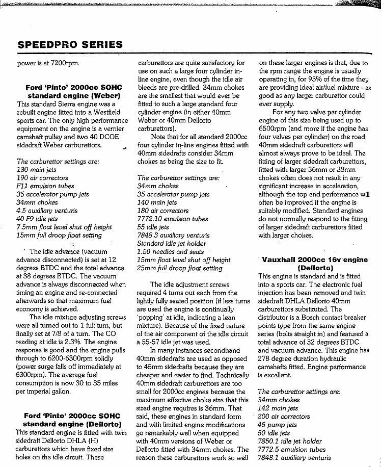
SPEEDPRO SERIES
power is at 7200rpm.
Ford 'Pinto' 2000cc SOHC standard engine (Weber)
This standard Sierra engine was a rebuilt engine fitted into a Westfield sports car. The only high performance equipment on the engine is a vernier camshaft pulley and two 40 DCOE sidedraft Weber carburettors.
The carburettor settings are: 130 main jets 190 air correctors Fll emulsion tubes 35 accelerator pump jets 34mm chokes 4.5 auxiliary venturis 40 F9 idle jets 7.5mm float level shut off height 15mm full droop float setting
' The idle advaoce (vacuum advance disconnected) is set at 12 degrees BTDC and the total advance at 38 degrees BTDC. The vacuum advance is always disconnected when timing an engine and re-connected afterwards so that maximum fuel economy is achieved.
The idle mixture adjusting screws were all turned out to 1 full turn, but finally set at 7/8 of a turn. The CO reading at idle is 2.3%. The engine response is good and the engine pulls through to 6200-6300rpm solidly (power surge falls off immediately at 6300rpm). The average fuel consumption is now 30 to 35 miles per imperial gallon.
Ford 'Pinto' 2000cc SOHC standard engine (Dellorto)
This standard engine is fitted with twin sidedraft Dellorto DHLA (H) carburettors which have fixed size holes on the idle circuit. These
carburettors are quite satisfactory for use on such a large four cylinder in-line engine, even though the idle air bleeds are pre-drilled. 34mm chokes are the smallest that would ever be fitted to such a large standard four cylinder engine (in either 40mm Weber or 40mm Dellorto carburettors).
Note that for all standard 2000cc four cylinder in-line engines fitted with 40mm sidedrafts consider 34mm chokes as being the size to fit.
The carburettor settings are: 34mm chokes 35 accelerator pump jets 140 main jets 180 air correctors 7772.10 emulsion tubes 55 idle jets 7848.3 auxiliary venturis Standard idle jet holder 1.50 needles and seats 15mm float level shut off height 25mm full droop float setting
The idle adjustment screws required 4 turns out each from the lightly fully seated position (if less turns are used the engine is continually 'popping' at idle, indicating a lean mixture). Because of the fixed nature of the air component of the idle circuit a 55-57 idle jet was used.
In many instances secondhand 40mm sidedrafts are used as opposed to 45mm sidedrafts because they are cheaper and easier to find. Technically 40mm sidedraft carburettors are too small for 2000cc engines because the maximum effective choke size that this sized engine requires is 36mm. That said, these engines in standard form and with limited engine modifications go remarkably well when equipped with 40mm versions of Weber or Dellorto fitted with 34mm chokes. The reason these carburettors work so well
on these larger engines is that, due to the rpm range the engine is usually operating in, for 95% of the time they are providing ideal air/fuel mixture as good as any larger carburettor could ever supply.
For any two valve per cylinder engine of this size being used up to 6500rpm (and more if the engine has four valves per cylinder) on the road, 40mm sidedraft carburettors will almost always prove to be ideaL The fitting of larger sidedraft carburettors, fitted with larger 36mm or 38mm chokes often does not result in any significant increase in acceleration, although the top end performance will often be improved if the engine is suitably modified. Standard engines do not normally respond to the fitting of larger sidedraft carburettors fitted with larger chokes.
Vauxhall 2000cc 16v engine (Dellorto)
This engine is standard and is fitted into a sports car. The electronic fuel injection has been removed and twin sidedraft DHLA Dellorto 40mm carburettors substituted. The distributor is a Bosch contact breaker points type from the same engine series (bolts straight in) and featured a total advance of 32 degrees BTDC and vacuum advance. This engine has 278 degree duration hydraulic camshafts fitted. Engine performance is excellent.
The carburettor settings are: 34mm chokes 142 main jets 200 air correctors 45 pump jets 50 idle jets 7850.1 idle jet holder 7772.5 ·emulsion tubes 7848.1 auxiliary venturis

15mm float level shut off height 25mm full droop float setting
The idle adjustment screws were all set to 3 1/2 turns out from the lightly seated position.
Ford RS 2000cc SOHC Escort (Weber)
The following settings were those required for good all round engine performance. This engine is bored out to 2094cc, has a Group 1 camshaft, Group 1 valves, standard replacement rockers and 10:1 compression ratio. The camshaft is timed 2 degrees retarded (110 degrees).
This engine is rewed to 7000rpm only, and is limited to that via the use of a modified -'governor rotor' as fitted to the points type Bosch distributor. The distributor does not have a vacuum advance mechanism (poor economy!). The idle speed (1200rpm) ignition timing is 18 degrees BTDC and the total advance, 'all in' at 3500rpm, is 38 degrees BTDC.
The idle adjustment screws are turned out one complete tum. This engine is very tractable.
The carburettor settings are: 38mm chokes 5.0 auxiliary uenturis F16 emulsion tubes 145 main jets 180 air correctors 40 accelerator pump jets 45F9 idle jets 50 accelerator pump inlet 7.5mm float level shut off height 15mm full droop float setting
Ford Sierra Cosworth 2000cc (naturally aspirated)(Weber)
This engine has a cylinder head which retains the standard valves, enlarged inlet and exhaust ports and L1 camshafts. The engine has 11:1
JETTING/SETTING EXAMPLES
compression and is equipped with two 45mm sidedraft Weber carburettors. The distributor is a Bosch points type with the vacuum advance retained. The idle speed advance at 1200 rpm is 20 degrees and the total advance is 32 degrees, 'all in' at 3400rpm. Maximum revs are limited to 7700rpm by means of an electronic cut-out and a mechanical governor rotor.
The carburettor settings are: F16 emulsion tubes. 38 mm chokes. 5.0 auxiliary uenturis. 40 accelerator pumps. 100 accelerator pump inlet. 45 F9 idle jets. 155 mains jets. 210 air correctors. 7.5mm float level shut off height 15.0mm full droop float setting
The idle mixture adjustment screws are set to 1 1/4turns out from the lightly seated position.
BMC B·Series 1900cc MGB engine (Weber)
Modified engine fitted with a 300 degree duration camshaft, a modified cylinder head and a single 45mm DCOE Weber carburettor.
The carburettor settings are: 36mm chokes F16 emulsion tubes 55 F9 idle jets Idle adjustment screws 2 3/4 tums out 50 accelerator pump jets 145 mains 160 air correctors 4.5 auxiliary uenturis 7.5mm float level shut off height 15mm full droop float setting
Idle advance is set at 15 degrees BTDC and total advance at 35
degrees BTDC. This amount of idle speed advance is about the limit and, occasionally, the engine will kick back on starting, especially when cold. The fact is that the engine runs better with this amount of idle speed advance, when the advance is reduced to give better starting the overall engine performance drops off.
Toyota 4A·GE 1600cc 16· valve MR2 engine (Weber)
This is an otherwise standard engine equipped with a pair of sidedraft 40mm Weber carburettors. This engine is distributor equipped, has 15 degrees of idle speed advance and 32 degrees of total advance and no vacuum advance. Engine runs very well.
The carburettor settings are: 34mm chokes 140 main jets 175 air correctors 35 pump jets 50 F11 idle jets F 16 emulsion tubes 4.5 auxiliary uenturis No hole in the accelerator pump inlet value 7.5mm fuel shut off height 15mm full droop float setting
MG 1940cc alloy 8 port Magnette engine (Weber)
This is an older engine prepared for classic racing. It uses a brand new cylinder head, as made by Alexander, and a late model BMC B-Series five main bearing cylinder block, crankshaft and connecting rods.
The carburettor settings are: 38mm chokes F 11 emulsion tubes 145 main jets
111
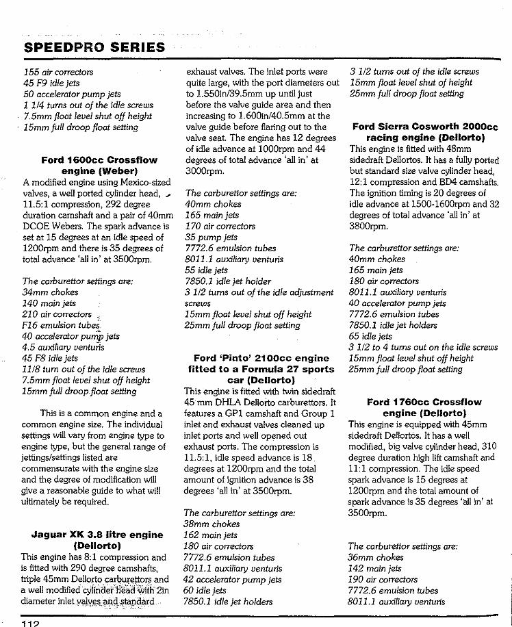
SPEEDPRO SERIES
155 air correctors 45 F9 idle jets 50 accelerator pump jets 1 114 turns out of the idle screws 7.5mm float level shut off height 15mm full droop float setting
Ford 1600cc Crossflow engine (Weber)
A modified engine using Mexico-sized valves, a well ported cylinder head, 11.5:1 compression, 292 degree duration camshaft and a pair of 40mm DCOE Webers. The spark advance is set at 15 degrees at an idle speed of 1200rpm and there is 35 degrees of total advance 'all in' at 3500rpm.
The carburettor settings are: 34mm chokes 140 main jets 210 air correctors F16 emulsion tubes40 accelerator pu,::P jets 4.5 auxiliary venturis45 F8 idle jets 1118 tum out of the idle screws 7.5mm float level shut off height 15mm full.droop float setting
This is a common engine and a common engine size. The individual settings will vary from engine type to engine type, but the general range of jettings/settings listed are commensurate with the engine size and the degree of modification will give a reasonable guide to what will ultimately be required.
Jaguar XK 3.8 litre engine (Dellorto)
This engine has 8:1 compression and is fitted with 290 degree camshafts, triple 45mm D"llorto carburettors and a well modified cylinder head with2in diameter inlet valves and standard... '-
1
exhaust valves. The inlet ports were quite large, with the port diameters out to 1.550in/39.5mm up until just before the valve guide area and then increasing to 1.600in/40.5mm at the valve guide before flaring out to the valve seat. The engine has 12 degrees of idle advance at 1000rpm and 44 degrees of total advance 'all in' at 3000rpm.
The carburettor settings are: 40mm chokes 165 main jets 170 air correctors 35 pump jets 7772.6 emulsion tubes 8011.1 auxiliary venturis 55 idle jets 7850.1 idle jet holder 3 1/2turnsout of the idle adjustment screws 15mm float level shut off height 25mm full droop float setting
Ford 'Pinto' 2100cc engine fitted to a Formula 27 sports
car (Dellorto) This engine is fitted with twin sidedraft 45 mm DHLA Dellorto carburettors. It features a GP1 camshaft and Group 1 inlet and exhaust valves cleaned up inlet ports and well opened out exhaust ports. The compression is 11.5:1, idle speed advance is 18 degrees at 1200rpm and the total amount of ignition advance is 38 degrees 'all in' at 3500rpm.
The carburettor settings are: 38mm chokes 162 main jets 180 air correctors 7772.6 emulsion tubes 8011.1 auxiliary venturis 42 accelerator pump jets 60 idle jets 7850.1 idle jet holders
3 112 turns out of the idle screws 15mm float level shut of height 25mm full droop float setting
Ford Sierra Cosworth 2000cc racing engine (Dellorto)
This engine is fitted with 48mm sidedraft Dellortos. It has a fully ported but standard size valve cylinder head, 12:1 compression and BD4 camshafts. The ignition timing is 20 degrees of idle advance at 1500-1600rpm and 32 degrees of total advance 'all in' at 3800rpm.
The carburettor settings are: 40mm chokes 165 main jets 180 air correctors 8011.1 auxiliary venturis 40 accelerator pump jets 7772.6 emulsion tubes 7850.1 idle jet holders 65 idle jets 3 112 to 4 turns out on the idle screws 15mm float level shut off height 25mm full droop float setting
Ford 1760cc Crossflow engine (Dellorto)
This engine is equipped with 45mm sidedraft Dellortos. It has a well modified, big valve cylinder head, 310 degree duration high lift camshaft and 11:1 compression. The idle speed spark advance is 15 degrees at 1200rpm and the total amount of spark advance is 35 degrees 'all in' at 3500rpm.
The carburettor settings are: 36mm chokes 142 main jets 190 air correctors 7772.6 emulsion tubes 8011.1 auxiliary venturis

58 idle jets 7580.1 idle jet holders
[ i 42 accelerator pump jets 15mm float level shut off height 25mm full drop float setting
BMC/Rover 1275cc A-series engine (Dellorto)
This well modified engine is fitted with
JETTING/SETTING EXAMPLES a 45mm Dellorto sidedraft carburettor. The ignition advance is 15 degrees at idle and 33 degrees full advance. The carburettor setting are: 36mm chokes 160 main jets 180 air correctors 7772.6 emulsion tubes 8011.1 auxiliary venturis 40 accelerator pump jets
58 idle jets 7580.1 idle jet holders 15mm float level shut off height 25mm full droop float setting
Visit Veloce on the Web www.veloce.co.uk 113

Glossary of terms
AMERICAN/ENGLISH GLOSSARY OF AUTOMOTIVE
TERMS
spanner (exhaust) Curve Corner Heat riser Hot spot
High Top gear Dashboard Facia Hood Bonnet (engine
American English Denatured alcohol Methylated spirit cover) Dome lamp Interior light Idle Tickover
A-arm Wishbone Drill gun Electric drill Intake Inlet (suspension) Driveaxle Driveshaft
Air horns Ram pipes Driveshaft Propeller shaft Jackstands Antenna Aerial /Safety stands Axle stands Axleshaft Halfshaft Fender Wing/mudguard Jumper cable Jump lead
Firewall Bulkhead Back-up Reverse Flashlight Torch Keeper Collet Barrel Choke/venturi Float bowl Float chamber Kerosene ParaffinBlock Chock/wedge Freeway, Knock pin Roll pin Box end wrench Ring spanner Bushing Bush
turnpike, etc. Motorway FreeplayFrozen Seized Lash Clearance
Clutch hub Synchro hub Gas tank Petrol tank Latch ·Catch Coast Freewheel Gas pedal Accelerator pedal Latches Locks Convertible Drop head Gasoline (gas) Petrol License plate Cotter pin Split pin Gearshift Gearchange /tag plate Number plate Counterclockwise Anti-clockwise Countershaft Layshaft (of
Generator (DC) Dynamo Light Lamp Ground Earth (electrical) Lock (for valve
. gearbox) spring retainer) Split cotter (for Crescent wrench Open-ended Header/manifold Manifold ... . yalve cap)
123

SPEEDPRO SERIES Lopes Lug nut
Metal chips or debris
Misses Muffler
Oil pan Open flame
HuntsWheel nut
Panel wagon/van VanParking light SidelightParking brake Handbrake
Piston pin or wrist pin Small (little)end
Piston pin or wrist pin
Pitman arm Power brake
booster Primary shoe
Prussian blue Pry
Pry bar Prying
Quarter window
bearing·
Gudgeon pinDrop arm
Servo unit Leading shoe (of brake) Engineer's blue Prise (force apart) Crowbar Levering
Quarter light
Recap Release cylinder Repair shop Replacement Ring gear
(of differential) Rocker panel Rod bearing Rotor/disk
Secondary shoe
Sedan Setscrew,
Allen screw Shift fork Shift lever
Shift rod Shock absorber,
shock Snap-ring Soft top Spacer Spare tire Spark plug wires Spindle arm Stablizer
or sway bar Station wagon Stumbles
Retread Slave cylinder Garage Renewal
CrownwheelSill panelBig-endbearing
' Disc (brake)
Trailing shoe(of brake)Saloon
Grub screw Selector fork Gearlever gearstick Selector rod
Damper/shocker Circlip Hood Distance piece Spare wheel HTleads Steering arm
Anti-roll bar Estate car Hesitates
Tang or lock Tab Taper pin Cotter pin Teardown Strip( down)
Throw-out bearing· dismantle Thrust bearing
Tie-rod (or connecting rod) Trackrod (of
steering) Transmission Gearbox Troubleshooting Fault finding
diagnosis Trunk Boot Tube wrench Box spanner Turn signal Indicator
Valve lifter Tappet Valve lifter or
tappet Cam follower or tappet
Valve cover Rocker cover VOM
(volt ohmmeter) Multimeter
Wheel cover Roadwheel trim Wheel well Wheelarch Whole drive line Transmission Windshield Windscreen Wrench Spanner
Visit Veloce on the Web- www.veloce.co.uk 124

Accelerator pump 19, 20 'Accelerator pump intake/discharge
valve 24, 25, 76, 77 Accelerator pump piston rods (Weber)
50 Accelerator pump jet selection 75-77 Accelerator pump jets 19 Accelerator pump jets-final selection
101, 102 Accelerator pump return springs 19 Acknowledgements 13 Adjusting idle by-pass systems 101 Air correctors 16-18 Air corrector-selection 73, 74 Air filters 60, 61 Air/fuel ratio readings 101, 102 Anti-vibration mountings 82, 83 Auxiliary venturi-selection 74-76
Body components (Dellorto) 41-48 Body components (Weber) 48-58 Butterfly removal 30-32 Butterflies (fitting) 35, 36 Butterfly securing screws 36
Camshaft timing versus idle speed 85
126
Index
Carburettor strip down (Weber and Dellorto) 22-28
Carburettor-checking fit 80-82 Carburettor/s-fitting to inlet manifold
84-84 Choke location screws 46, 101 Choke size-selecting 65-6 7 Choke size versus carburettor size 64,
65 Choke sizes- selecting 65, 67, 103 Chokes and auxiliary venturis 15, 16 Choosing the tuning components for
your carburettor 64 Cleaning components 22, 23 Clearing passageways 29 Component inspection (Weber &
Dellorto) 28, 29 Components - initial selection 64-78 CO readings 101, 102
Dellorto accelerator pump 21, 47, 48 Dellorto accelerator pump jets/plugs
45,46 Dellorto butterfly fitting 36 Dellorto exploded view diagram &
parts listing 26, 27
Dellorto floats 21, 42, 43 Dellorto fuel filter 46, 59 Dellorto idle jets and holders 20, 67-
70,97,98 Dellorto idle jet codes 68, 69 Dellorto needle and seat 21 Dellorto progression hole plugs 45 DC03 carburettors 10, 11 DCO/SP Weber carburettors 50-52 Difficult procedures 29-38
Emission controlled Weber or Dellorto carburettors 13, 38-40
Emission controlled Weber carburettors (idle jets) 68
Emulsion tubes 16, 19 Emulsion tube selection (Weber/
Dellorto) 71-73 Essential information 14
Facetfuel pump 63, 107 Fitting butterflies 35-36 Float level setting (Dellorto) 42, 43 Float level setting (brass float Weber)
49,50 Float level setting (Spansil float
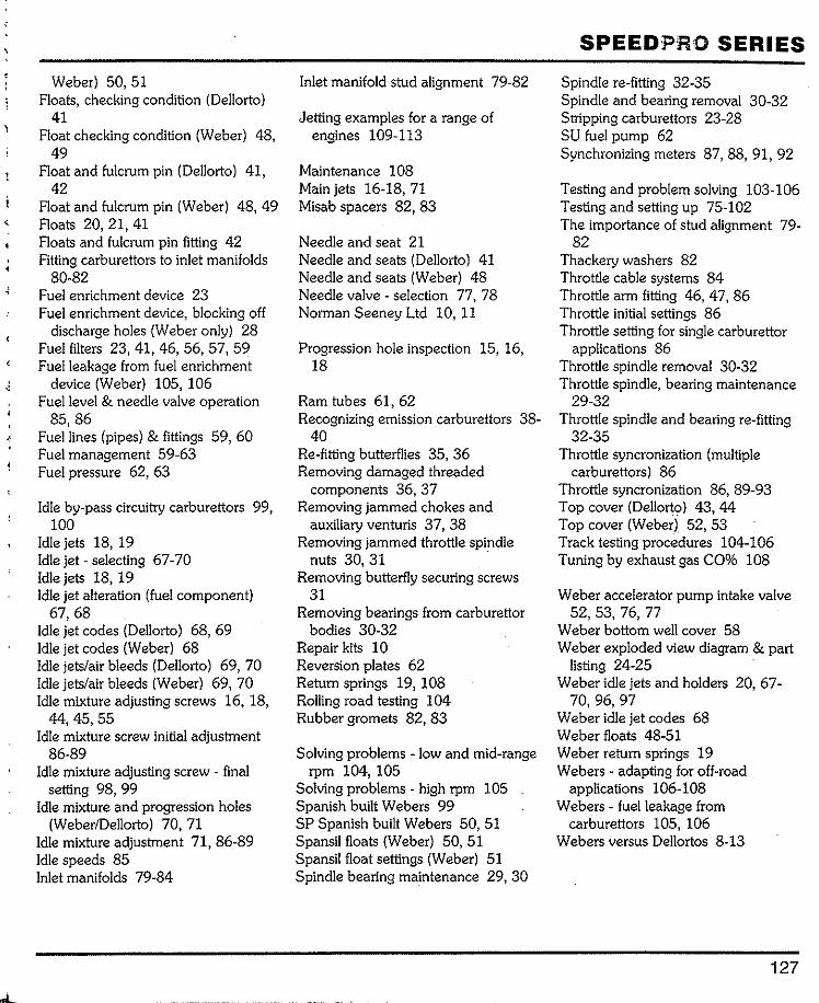
'
Weber) 50, 51 Floats, checking condition (Dellorto)
41 Float checking condition (Weber) 48,
49 Float and fulcrum pin (Dellorto) 41,
42 Float and fulcrum pin (Weber) 48, 49 Floats 20, 21, 41 Floats and fulcrum pin fitting 42 Fitting carburettors to inlet manifolds
80-82 Fuel enrichment device 23 Fuel enrichment device, blocking off
discharge holes (Weber only) 28 Fuel filters 23, 41, 46, 56, 57, 59 Fuel leakage from fuel enrichment
device (Weber) 105, 106 Fuel level & needle valve operation
85,86 Fuel lines (pipes) & fittings 59, 60 Fuel management 59-63 Fuel pressure 62, 63
Idle by-pass circuitry carburettors 99, 100
Idle jets 18, 19 Idle jet - selecting 67-70 Idle jets 18, 19 Idle jet alteration (fuel component)
67,68 Idle jet codes (Dellorto) 68, 69 Idle jet codes (Weber) 68 Idle jets/air bleeds (Dellorto) 69, 70 Idle jets/air bleeds (Weber) 69, 70 Idle mixture adjusting screws 16, 18,
44,45,55 Idle mixture screw initial adjustment
86-89 Idle mixture adjusting screw - final
setting 98, 99 Idle mixture and progression holes
(Weber/Dellorto) 70, 71 Idle mixture adjustment 71, 86-89 Idle speeds 85 Inlet manifolds 79-84
Inlet manifold stud alignment 79-82
Jetting examples for a range of engines 109-113
Maintenance 108 Main jets 16-18, 71 Misab spacers 82, 83
Needle and seat 21 Needle and seats (Dellorto) 41 Needle and seats (Weber) 48 Needle valve- selection 77, 78 Norman Seeney Ltd 10, 11
Progression hole inspection 15, 16, 18
Ram tubes 61, 62 Recognizing emission carburettors 38-
40 Re-fitting butterflies 35, 36 Removing damaged threaded
components 36, 37 Removing jammed chokes and
auxiliary venturis 37, 38 Removing jammed throttle spindle
nuts 30, 31Removing butterfly securing screws
31 Removing bearings from carburettor
bodies 30-32 Repair kits 10 Reversion plates 62 Return springs 19, 108 Rolling road testing 104 Rubber gromets 82, 83
Solving problems - low and mid-range rpm 104, 105
Solving problems - high rpm 105 Spanish built Webers 99 SP Spanish built Webers 50, 51 Spansilfloats (Weber) 50, 51 Spansil float settings (Weber) 51 Spindle bearing maintenance 29, 30
SPEEDPRO SERIES
Spindle re-fitting 32-35 Spindle and bearing removal 30-32 Stripping carburettors 23-28 SU fuel pump 62 Synchronizing meters 87, 88, 91, 92
Testing and problem solving 103-106 Testing and setting up 75-102 The importance of stud alignment 79-
82 Thackery washers 82 Throttle cable systems 84 Throttle arm fitting 46, 47, 86 Throttle initial settings 86 Throttle setting for single carburettor
applications 86 Throttle spindle removal 30-32 Throttle spindle, bearing maintenance
29-32 Throttle spindle and bearing re-fitting
32-35 Throttle syncronization (multiple
carburettors) 86 Throttle syncronization 86, 89-93 Top cover (Dellorto) 43, 44 Top cover (Weber) 52, 53 Track testing procedures 104-106 Tuning by exhaust gas CO% 108
Weber accelerator pump intake valve 52,53, 76,77
Weber bottom well cover 58 Weber exploded view diagram & part
listing 24-25 Weber idle jets and holders 20, 67-
70,96,97 Weber idle jet codes 68 Weber floats 48-51 Weber return springs 19 Webers - adapting for off-road
applications 106-108 Webers- fuel leakage from
carburettors 105, 106 Webers versus Dellortos 8-13
127