tunnels, shaft and development headings blast design 2013tac workshop... · revey associates, inc....
TRANSCRIPT
REVEY Associates, Inc. 2005 Page 1
TUNNELS, SHAFT AND
DEVELOPMENT HEADINGS BLAST DESIGN
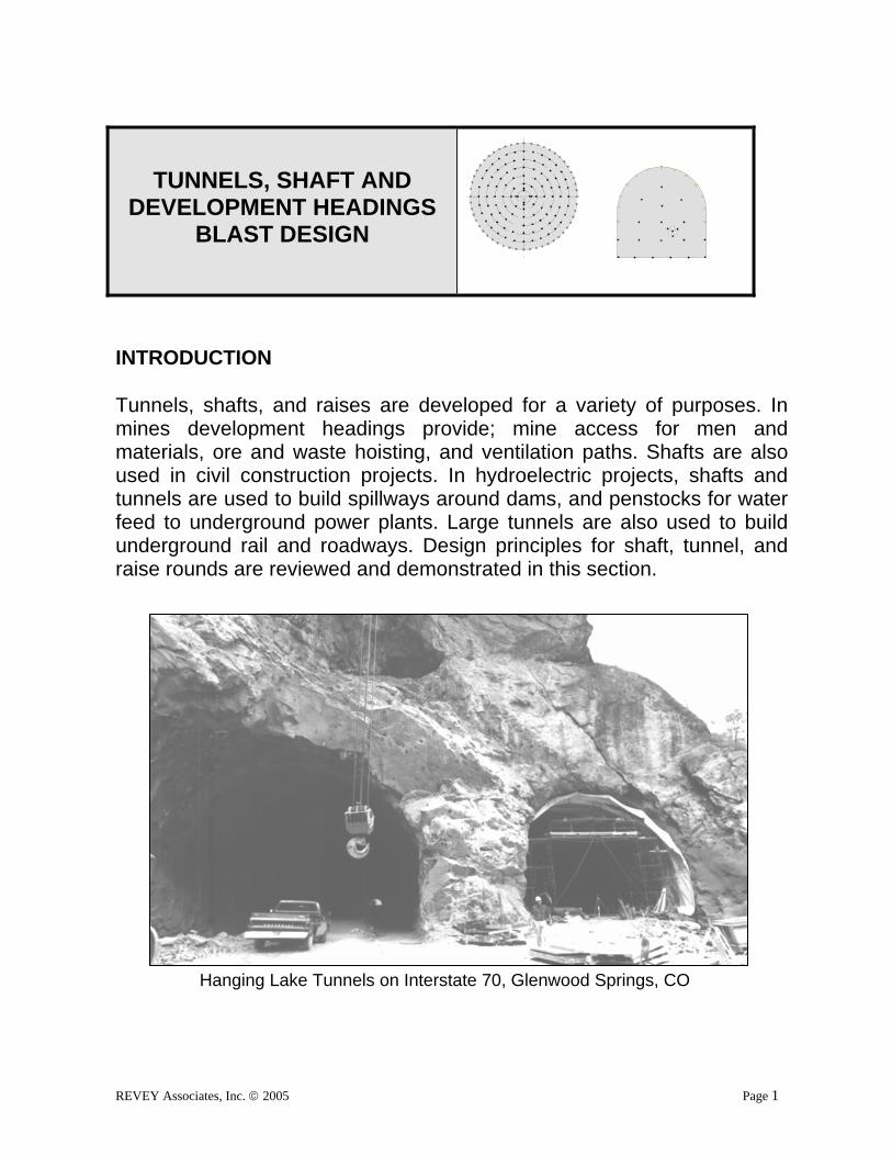
INTRODUCTION Tunnels, shafts, and raises are developed for a variety of purposes. In mines development headings provide; mine access for men and materials, ore and waste hoisting, and ventilation paths. Shafts are also used in civil construction projects. In hydroelectric projects, shafts and tunnels are used to build spillways around dams, and penstocks for water feed to underground power plants. Large tunnels are also used to build underground rail and roadways. Design principles for shaft, tunnel, and raise rounds are reviewed and demonstrated in this section.
Hanging Lake Tunnels on Interstate 70, Glenwood Springs, CO

Underground Blasting Technology ______________________________________________________________
REVEY Associates, Inc. 2010 Page 2
DEFINING REQUIREMENTS AND CONDITIONS In an ideal situation, designers would have unlimited choices regarding explosives selection, and drilling equipment. However in most situations, blast designers do not have complete control over all of the variables affecting blast design. Round dimensions are usually pre-set, and designers must often accept the limitations that come with using existing drilling equipment drilling equipment. Despite some limitations, many other design elements can be adjusted to improve round design. Drill patterns and explosive loads can be modified, and within drilling equipment limits, hole-size can be changed. Following, is a list of typical considerations that designers should define when they develop new, or attempt improvement to existing, heading rounds.
HEADING ROUND DESIGN CONSIDERATIONS
1. Heading production goals; advance rates, and schedule.
2. Ground conditions; rock strength and structure.
3. Shaft or tunnel excavation dimensions.
4. Overbreak limitations, and perimeter loading specifications.
5. Vibration and airblast limits.
6. Existing limitations; drills, bit size, environmental, etc.
7. Labor factors; experience and work rules.
8. Company safety policy and goals.
_____________________________________________Tunnels, Shaft, and Development Headings Blast Design
REVEY Associates, Inc. 2005 Page 3
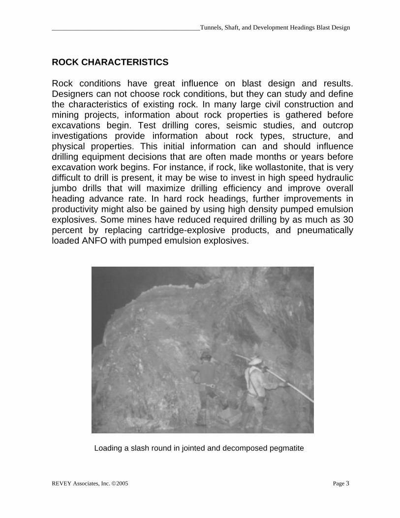
ROCK CHARACTERISTICS Rock conditions have great influence on blast design and results. Designers can not choose rock conditions, but they can study and define the characteristics of existing rock. In many large civil construction and mining projects, information about rock properties is gathered before excavations begin. Test drilling cores, seismic studies, and outcrop investigations provide information about rock types, structure, and physical properties. This initial information can and should influence drilling equipment decisions that are often made months or years before excavation work begins. For instance, if rock, like wollastonite, that is very difficult to drill is present, it may be wise to invest in high speed hydraulic jumbo drills that will maximize drilling efficiency and improve overall heading advance rate. In hard rock headings, further improvements in productivity might also be gained by using high density pumped emulsion explosives. Some mines have reduced required drilling by as much as 30 percent by replacing cartridge-explosive products, and pneumatically loaded ANFO with pumped emulsion explosives.
Loading a slash round in jointed and decomposed pegmatite
Underground Blasting Technology ______________________________________________________________
REVEY Associates, Inc. 2010 Page 4
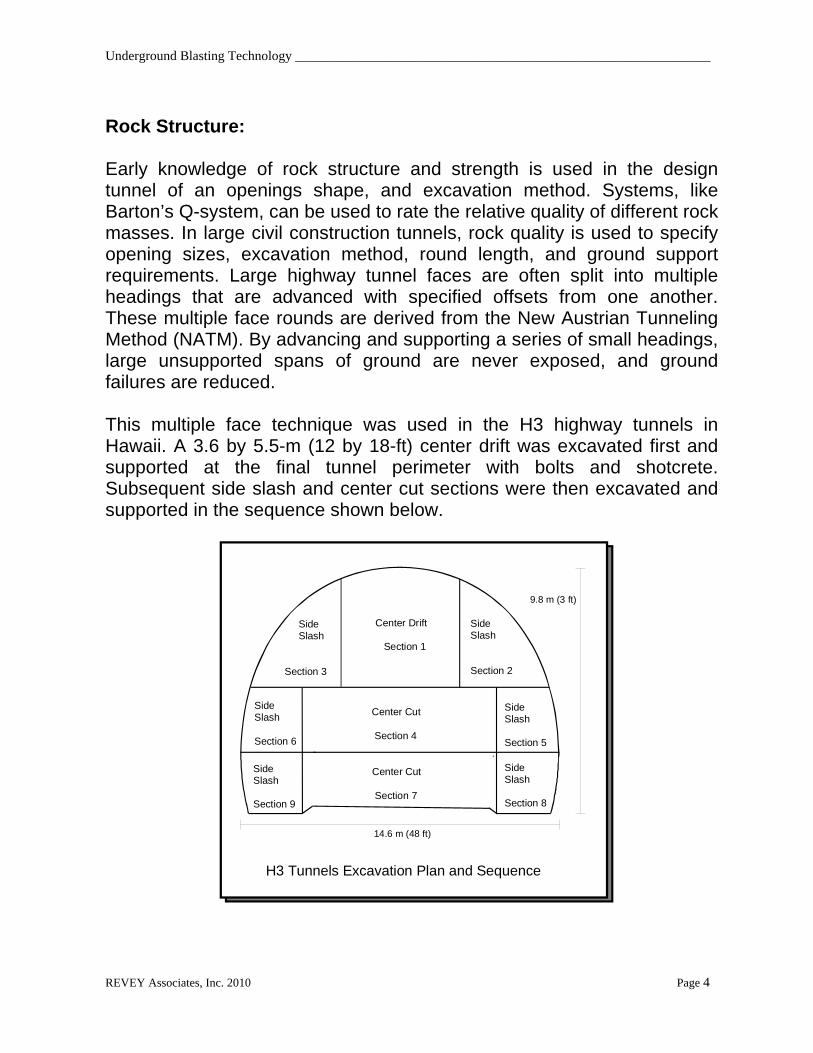
Rock Structure: Early knowledge of rock structure and strength is used in the design tunnel of an openings shape, and excavation method. Systems, like Barton’s Q-system, can be used to rate the relative quality of different rock masses. In large civil construction tunnels, rock quality is used to specify opening sizes, excavation method, round length, and ground support requirements. Large highway tunnel faces are often split into multiple headings that are advanced with specified offsets from one another. These multiple face rounds are derived from the New Austrian Tunneling Method (NATM). By advancing and supporting a series of small headings, large unsupported spans of ground are never exposed, and ground failures are reduced. This multiple face technique was used in the H3 highway tunnels in Hawaii. A 3.6 by 5.5-m (12 by 18-ft) center drift was excavated first and supported at the final tunnel perimeter with bolts and shotcrete. Subsequent side slash and center cut sections were then excavated and supported in the sequence shown below.
H3 Tunnels Excavation Plan and Sequence
Side Slash
Section 3
Center Drift
Section 1
SideSlash
Section 2
Center Cut
Section 4
SideSlash
Section 5
SideSlash
Section 6
SideSlash
Section 9
SideSlash
Section 8
Center Cut
Section 7
9.8 m (3 ft)
14.6 m (48 ft)
_____________________________________________Tunnels, Shaft, and Development Headings Blast Design
REVEY Associates, Inc. 2005 Page 5
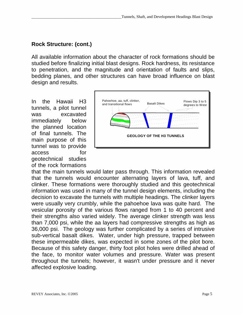
Rock Structure: (cont.) All available information about the character of rock formations should be studied before finalizing initial blast designs. Rock hardness, its resistance to penetration, and the magnitude and orientation of faults and slips, bedding planes, and other structures can have broad influence on blast design and results. In the Hawaii H3 tunnels, a pilot tunnel was excavated immediately below the planned location of final tunnels. The main purpose of this tunnel was to provide access for geotechnical studies of the rock formations that the main tunnels would later pass through. This information revealed that the tunnels would encounter alternating layers of lava, tuff, and clinker. These formations were thoroughly studied and this geotechnical information was used in many of the tunnel design elements, including the decision to excavate the tunnels with multiple headings. The clinker layers were usually very crumbly, while the pahoehoe lava was quite hard. The vesicular porosity of the various flows ranged from 1 to 40 percent and their strengths also varied widely. The average clinker strength was less than 7,000 psi, while the aa layers had compressive strengths as high as 36,000 psi. The geology was further complicated by a series of intrusive sub-vertical basalt dikes. Water, under high pressure, trapped between these impermeable dikes, was expected in some zones of the pilot bore. Because of this safety danger, thirty foot pilot holes were drilled ahead of the face, to monitor water volumes and pressure. Water was present throughout the tunnels; however, it wasn't under pressure and it never affected explosive loading.
Flows Dip 3 to 5 degrees to WestBasalt Dikes
Pahoehoe, aa, tuff, clinker,and transitional flows
GEOLOGY OF THE H3 TUNNELS

Underground Blasting Technology ______________________________________________________________
REVEY Associates, Inc. 2010 Page 6
Rock Structure: (cont.) However, the loosely cemented clinker had great influence on drilling and blasting productivity. Drilling in the crumbly clinker zones was extremely difficult. Holes were drilled relatively fast but cleaning them and keeping them open was hard to do. Drilling in the clinker areas was similar to drilling into a loosely cemented gravel pile. As soon as the drill steel was removed, rock chunks would fall in, block the hole, and subsequently more time was spent clearing holes then drilling them. The presence of open caves or large vugs can also influence blast design. In the fluorspar mines in Illinois, 1 to 2 m (3 to 6 ft) wide vugs commonly occurred in heading round faces. When the vugs extended the full depth of the round, drill pattern and timing sequence were modified to take advantage of the opening. Holes were drilled and delayed to slash rock into the open vug and the need for a burn cut was eliminated. In civil excavations, large caves are usually backfilled with concrete.
Modified Round With Large Vug in Face
Cave
1
23
4
2
4
5
6
5
7
16 17
9
8
13 1412111010111213
4
5
16 15 15 1517
Large vug used for relief and Burn cut is eliminated

_____________________________________________Tunnels, Shaft, and Development Headings Blast Design
REVEY Associates, Inc. 2005 Page 7
PRODUCTION REQUIREMENTS AND EQUIPMENT LIMITATIONS The equipment used in tunnels and other development headings has great influence on productivity. Many contractors, mining companies, and manufacturers have put much effort into the development of mechanized equipment and techniques that have improved heading advance rates. New “super” pneumatic jumbo drills have penetration rates as high as 180 m/hr (505 ft/hr). Explosive loading rates have also improved due to concurrent improvements in bulk explosives and mechanized charging equipment. These improvements have kept drilling and blasting competitive with other mechanical excavation methods. HEADING ROUND DESIGN Some reference books offer complex and scientific methods for determining the “ideal” round design. Some of the approaches that these books present are sound in principle, but they often do not work very well when they are applied to rock that is very different from the rock in which they were developed. Many general hard-rock blasting guidelines do not apply well to some of the soft and weak rock formations that are common in many of the western states of the U.S. After determining design objectives and equipment limitations, parts or all of the following guidelines can be used to establish initial heading round designs. This method is based on practical experience derived from actual blast designs done for over 100 different mines and construction projects.
Modern Shaft Sinking Equipment

Underground Blasting Technology ______________________________________________________________
REVEY Associates, Inc. 2010 Page 8
PenetrationRate Improvements, after Holdo, 1980
Bar & Armand Jack-legs
Semi-mechanized
MechanizedPneumaticDrills
300 m/hr984 ft/hr
MechanizedHudraulicDrills
1900 10 20 30 40 50 60 70 80 90 2000
20
40
60
80
100
120
140
160
280
200
220
240
260
280
300
_____________________________________________Tunnels, Shaft, and Development Headings Blast Design
REVEY Associates, Inc. 2005 Page 9
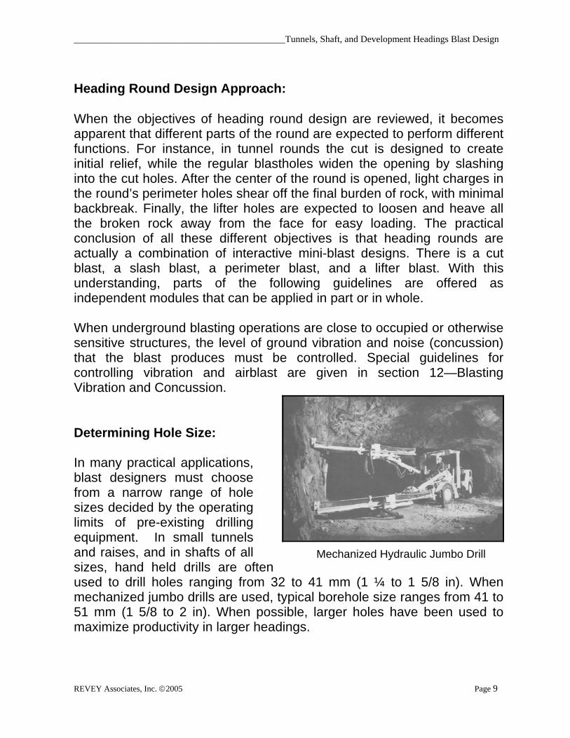
Heading Round Design Approach: When the objectives of heading round design are reviewed, it becomes apparent that different parts of the round are expected to perform different functions. For instance, in tunnel rounds the cut is designed to create initial relief, while the regular blastholes widen the opening by slashing into the cut holes. After the center of the round is opened, light charges in the round’s perimeter holes shear off the final burden of rock, with minimal backbreak. Finally, the lifter holes are expected to loosen and heave all the broken rock away from the face for easy loading. The practical conclusion of all these different objectives is that heading rounds are actually a combination of interactive mini-blast designs. There is a cut blast, a slash blast, a perimeter blast, and a lifter blast. With this understanding, parts of the following guidelines are offered as independent modules that can be applied in part or in whole. When underground blasting operations are close to occupied or otherwise sensitive structures, the level of ground vibration and noise (concussion) that the blast produces must be controlled. Special guidelines for controlling vibration and airblast are given in section 12—Blasting Vibration and Concussion. Determining Hole Size: In many practical applications, blast designers must choose from a narrow range of hole sizes decided by the operating limits of pre-existing drilling equipment. In small tunnels and raises, and in shafts of all sizes, hand held drills are often used to drill holes ranging from 32 to 41 mm (1 ¼ to 1 5/8 in). When mechanized jumbo drills are used, typical borehole size ranges from 41 to 51 mm (1 5/8 to 2 in). When possible, larger holes have been used to maximize productivity in larger headings.
Mechanized Hydraulic Jumbo Drill

Underground Blasting Technology ______________________________________________________________
REVEY Associates, Inc. 2010 Page 10
Determining Hole Orientation: In most headings it is a simple matter to decide whether horizontal or vertical or angled holes will be used the drill the round. Conventional shafts and raises are drilled with vertical holes, with some angled holes in the cut if a pyramid or swing cut is used for opening the round. Small tunnel headings generally use horizontal holes. Drill holes in slot and rock pass raises and are often drilled on angles determined by the dip and strike of ore bodies. In large tunnels with multiple faces, lower bench rounds can be excavated with either vertical or horizontal holes. Vertical holes can be used when the sides or ribs of the tunnel are vertical or near vertical. Since vertical holes break laterally to open free faces, they produce good breakage with relatively low powder factors. When the tunnel sides or invert is curved, horizontal holes can be better positioned and aligned to reduce overbreak. The jumbo drill that drills the top heading rounds can also be to drill horizontal bench holes, hence improving utilization of expensive drilling equipment.

_____________________________________________Tunnels, Shaft, and Development Headings Blast Design
REVEY Associates, Inc. 2005 Page 11

Underground Blasting Technology ______________________________________________________________
REVEY Associates, Inc. 2010 Page 12
Determining Round Length: When high heading advance-rates are desired, drilling and blasting cycles are most productive when round length is maximized. The practical length of heading rounds is limited by the type of cut used and its effectiveness. If V cuts or swing cuts are used, the advance is limited by physical width of the heading and the angle of the cut. Most operations use burn cuts, because well designed burn cuts will allow the greatest advance. Drilling accuracy also influences the depth that rounds can break. After optimizing all of these factors, most operators settle on round depths that consistently break 95% of the hole. It is inefficient to drill any deeper than this limit. Some mining contractors have fitted in-the-hole hammer drills on tunnel and shaft jumbos to enable them to drill one or several very large open cut holes. These large cut holes can be drilled much deeper than regular drilling technology allows for a group of smaller parallel holes. Using this new technology, a Canadian contractor achieved an average advance of 4.7 meters (15.4 ft) per day at a large shaft sinking job. Determining Powder Factor: Most practical blast designers do not use tables or charts to determine initial powder factors for heading rounds. Since the different parts of a round are designed for different purposes, forcing the entire design to meet a preconceived powder factor or set number of holes is difficult and often counterproductive. Powder factors vary widely, depending on rock conditions, cut design, round length, and amount of relief. In the Hanging Lake highway tunnels in Colorado, side-slash rounds produced well broken and displaced rock with a powder factor of 1.1 kg/m3 (1.9 lb/yd3). When the same rock was blasted in floor-bench-rounds the powder factor was increased to 1.5 kg/m3 (2.5 lb/yd3). For bench blasting results similar to the top side-slash rounds, extra energy was needed to compensate for the successively increased weight of the broken rock covering unbroken rock above charges in rows of holes drilled near the floor – especially the bottom row “Lifters.”
_____________________________________________Tunnels, Shaft, and Development Headings Blast Design
REVEY Associates, Inc. 2005 Page 13
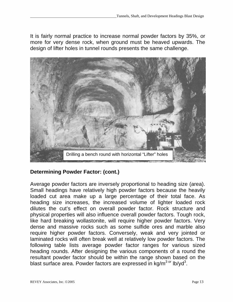
It is fairly normal practice to increase normal powder factors by 35%, or more for very dense rock, when ground must be heaved upwards. The design of lifter holes in tunnel rounds presents the same challenge.
Determining Powder Factor: (cont.) Average powder factors are inversely proportional to heading size (area). Small headings have relatively high powder factors because the heavily loaded cut area make up a large percentage of their total face. As heading size increases, the increased volume of lighter loaded rock dilutes the cut’s effect on overall powder factor. Rock structure and physical properties will also influence overall powder factors. Tough rock, like hard breaking wollastonite, will require higher powder factors. Very dense and massive rocks such as some sulfide ores and marble also require higher powder factors. Conversely, weak and very jointed or laminated rocks will often break well at relatively low powder factors. The following table lists average powder factor ranges for various sized heading rounds. After designing the various components of a round the resultant powder factor should be within the range shown based on the blast surface area. Powder factors are expressed in kg/m3 or lb/yd3.
Drilling a bench round with horizontal “Lifter” holes

Underground Blasting Technology ______________________________________________________________
REVEY Associates, Inc. 2010 Page 14
HEADING ROUND POWDER FACTOR RANGE TABLE
Face area Powder Factor Range
(m2) (ft2) (Kg/m3) (lb/yd3)low high low high
3.7 40 3.3 7.0 5.5 11.74.6 50 2.9 6.3 4.9 10.55.6 60 2.7 5.7 4.5 9.66.5 70 2.4 5.2 4.1 8.77.4 80 2.0 4.4 3.4 7.48.4 90 1.8 3.8 3.0 6.59.3 100 1.5 3.1 2.5 5.3
18.6 200 1.2 2.6 2.0 4.427.9 300 1.0 2.1 1.6 3.537.2 400 0.8 1.8 1.4 3.046.4 500 0.8 1.6 1.3 2.7
Design A Cut: The main difference between heading round blasting and bench blasting is that in tunnels and shaft blasting the round is directed towards one free face, while in bench blasting, the round is directed towards two or more free faces. In heading rounds, blast holes have no natural lateral relief. This constriction creates the need to establish and a second free face to which the rock can break to and be displaced. This second free face is produced by positioning and orienting blastholes that open up a “cut” that provides lateral break (stoping) relief for subsequent blastholes.
In development headings and tunnels, it is usually desirable to complete a cycle of drilling, blasting, and mucking in one shift. Factors such as the number and type of drills, the amount of advance, and the size of the equipment must be evaluated. The size of the opening is also a major factor in determining both the type of equipment and the depth of pull obtained, which usually is no greater than the least dimension of the drift. The two most common types of cuts employed in development drifting are burn cuts and V cuts. Many variations of each type are possible, depending on the rock conditions, drilling equipment, and other work conditions.

_____________________________________________Tunnels, Shaft, and Development Headings Blast Design
REVEY Associates, Inc. 2005 Page 15
Cut Location: In tunnels, adequate rock heave (muck loosening), balanced muck piles, and round relief are achieved when the cut is placed in the middle of the round face. When the cut is placed too low on the face, fragmentation is coarser and muck piles are tighter. With higher cuts, muck piles are generally more spread out and loose. In Canada, it is required to offset the cut from center of the round, so it can be alternated from side to side in successive faces. By offsetting the cut like this, it can always be located at least 3 feet away from its present position in the next round. This practice is intended to prevent the possibility of collaring holes in boot-legs, from the previous cut, that might contain misfired explosives.
Cut Type: There are essentially two types of cuts that are commonly used in heading round blasting; they are burn cuts and angled cuts. Angled cuts include “V” or wedge cuts, fan cuts, and drag cuts. Angled cuts are not commonly used because they generally produce less round advance than a burn cut in a similar heading. The physical application of angled cuts is also limited by heading dimensions, because only relatively wide headings have enough room to accommodate the drill head when it is set up for angled drilling. For these reasons, burn cuts are far more popular than angled cuts. Consequently, only a brief review of angled cuts is given in this section, and burn cuts are covered in detail. Angled Cuts
The “V” or wedge cut uses a set of holes forming a wedge in the middle of the face. When compared to bum rounds, V cuts use fewer holes and have lower powder factors. The fragmentation is coarser and because of the design of the round, the muckpile profile is usually lower and more spread out. The depth of pull with a V-cut is usually limited to about half the width of the heading because of the space required to set up and drill the angled holes. Rounds break better when the angle of the V-cut is at least 60 degrees. If the internal angle becomes too small (less than 60 degrees), it may be necessary to use a Baby-V or a Double-V, as shown in the following diagram.

Underground Blasting Technology ______________________________________________________________
REVEY Associates, Inc. 2010 Page 16
Typical "V" Cut Round
Space neededfor a mechanizeddrill feed
Like V-cut rounds, fan cuts and drag cuts use fewer holes and a lower powder factor than burn cut rounds. To maintain proper advance, these rounds are alternated from side to side. For each foot of hole drilled, the amount of advance per round is less than a burn cut round because the holes are drilled at an angle to the direction of advance. A pyramid cut blast design employs holes laid out in concentric cones of holes inclined so as to bottom out close to each other. The cut normally consists of five to eight evenly spaced holes angled inward at approximately 30 degrees and somewhat deeper than the rest of the holes in the round, so as to provide a sump for the next mining cycle. In massive hard rock, extra shallow "breaker" holes are often added to the center of the pyramid cut to improve rock breakage in the pyramid cut wedge area.

_____________________________________________Tunnels, Shaft, and Development Headings Blast Design
REVEY Associates, Inc. 2005 Page 17
Fan Cut Round
1 2 3 4 5
1 2 3 4 5
6
6
7
7
11 11 1212
8 7 7 8
109910
Timing Sequence

Underground Blasting Technology ______________________________________________________________
REVEY Associates, Inc. 2010 Page 18
Trim Hole Blastholes
DoublePyramid Cut
Shallow Shaft Round With Pyramid Cut(Large Civil Shaft for Access to Underground Rail Station)
SUMP
104 Blastholes 52 Trim Holes156 Total Holes

_____________________________________________Tunnels, Shaft, and Development Headings Blast Design
REVEY Associates, Inc. 2005 Page 19
Burn Cuts In recent years, almost all tunnel contractors are using burn cut rounds in place of V-cuts and swing cuts. Most contractors and miners find that round advance is maximized with burn cuts. They also learn that maximum round advance invariably lowers excavation costs. The design of burn cuts is truly a mixture of science and art. Books are full of complex charts and tables that one can use to design the perfect burn cut. However, in some applications even the most scientifically designed burn cuts do not work. Fortunately, from past experience, most experienced miners can usually develop cuts that work in varying conditions. Principal advantages of the burn cut are: 1. The depth of the round is not dependent on the working space
available for drilling holes at an angle. 2. The burn cut allows a deep pull even in tough rock formations. 3. It is relatively simple to drill, because all holes are parallel. 4. There is generally less throw with better fragmentation. 5. The resultant muckpile is higher, so it provides a better platform for
scaling and bolting work. 6. Round length may be shortened or lengthened without any difficulty. Principal disadvantages of the burn cut are: 1. The burn or relief holes are generally larger than the drill holes in the
drill holes in the round, and therefore require reaming or larger drilling equipment.
2. Drilling and explosives requirements (powder factor) are higher. 3. Drilling must be accurate or results will be unfavorable.

Underground Blasting Technology ______________________________________________________________
REVEY Associates, Inc. 2010 Page 20
Burn Cuts (cont.) The development and widespread use of water based explosives has created new burn cut design challenges. These explosives are very susceptible to pre-compression failure when they are used in tightly spaced cut holes. The following guidelines include specific recommendations for designing cuts with water based explosives, in addition to many general design considerations. Burn cuts are generally overcharged to compensate for drilling errors. However, overloading holes in the burn can cause the burn to "freeze" and fail. Excess energy can physically compact the broken rock fragments in place, instead of ejecting them from the burn. Only a limited amount of explosives energy is needed to shatter the rib of rock between the loaded holes and the empty bum holes, and eject it from the cut. In hard rock formations, the loaded cut holes should be loaded almost to the collar to ensure complete breakage. The following guidelines can be used to minimize cut "freezing": 1. Carefully align and drill all cut holes to ensure that they are parallel. 2. Provide more or large uncharged relief holes to accommodate the
"swell" of broken rock 3. Reduce the explosives energy per meter of blasthole in the cut (e.g.
use smaller diameter packaged explosives or an ANFO-polystyrene mixture in the cut holes).
4. Alter the geometry and spacing of the cut blastholes and relief holes,
to allow for changes in ground conditions. 5. In rock-types which tend to "freeze", use diamond holes that are
angled inwards at the toe, to assist ejection of rock broken by the cut. 6. Ensure that blastholes in the cut area fire in a controlled sequence,
with adequate time between successive detonations.
_____________________________________________Tunnels, Shaft, and Development Headings Blast Design
REVEY Associates, Inc. 2005 Page 21
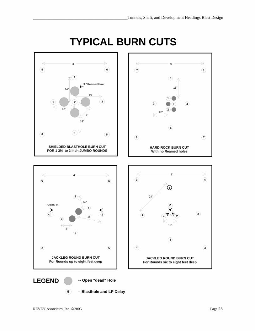
Bum Cuts (cont.) To further aid rock ejection from the burn, a small "kicker" or "booster" charge can be placed at the bottom of the normally empty void holes. These charges are delayed to fire just after the other fully loaded holes in the immediate cut have fired. Generally, long period delays are used to ensure that there is sufficient time for the rock from each hole, or group of holes, to break and be ejected from the cut, before subsequent holes fire. Some amount of boot-leg normally occurs in the burn area. When this occurs, a similar or greater length of advance is usually lost in the rest of the face area. To minimize this lost advance, when drill-steel-length allows it, the burn cut holes should be over-drilled by 15 to 30 cm (6 to 12 in). If this extra drilling for a few holes returns an equal length of advance for the whole face, it is well worth the investment in extra drilling. When NG based explosives are used in bum cuts, they usually fire as delayed or they propagate (fire instantaneously). In either case, all of the dynamite usually fires, whether it successfully pulls the cut or not. In Section 3-- Blasting Physics and Rock Properties, the subject of pre-compression failures is thoroughly covered. Water based emulsion or water-gel explosives are most susceptible to dead-pressing failure when they are used in closely spaced holes. By design, burn cuts always use closely spaced holes, and hence these failures are often found in or near the burn cut area of the face. When emulsion-cartridge explosives are used in burn cuts, open relief holes should be placed between the loaded cut holes to reduce hole to hole shock pressures. A burn cut showing this configuration is shown in the top-left example in the following Figure titled Typical Burn Cuts.

Underground Blasting Technology ______________________________________________________________
REVEY Associates, Inc. 2010 Page 22
Bum Cuts (cont.) Note: when larger blastholes are used, it is not practical to greatly increase the distance between the blastholes and uncharged relief holes. Increasing this distance is best achieved by increasing the diameter and/or the number of relief holes. Any increase in loaded cut hole spacing should be accompanied by a corresponding increase in the number and/or diameter of relief holes. In most rock types, the percentage of void space in the cut should remain above 15%. BURN CUT DESIGN CONSIDERATIONS SUMMARY 1. If the burn cut fails due to pre-compression, try spreading the loaded
holes farther apart. Adding more tightly spaced holes will aggravate the problem and unnecessarily increase costs. In soft or seamy rock adjacent loaded holes that are separately delayed, should be at least 30 cm (12 in) apart.
2. To pull rounds deeper than 8 feet, use burn cut designs with an
adequate volume of open relief holes. In rounds exceeding 8 feet, the relief-hole area should be at least 25 % of the total area in the immediate cut.
3. In weak seamy ground, the “shielded” burn cut design (top-left) in the
following examples demonstrates this practice. 4. In hard rock, faster timing between cut holes often improves cut
performance. Some operators have used intermediate or 1/4 and 1/2 delays to speed up the cut firing sequence by generating 100 millisecond - hole to hole -- delay intervals. Other operations have used short period delay detonators, with 50 millisecond intervals, to improve cut performance.
_____________________________________________Tunnels, Shaft, and Development Headings Blast Design
REVEY Associates, Inc. 2005 Page 23
Z1
2
3
4
5
56
6
3 " Reamed Hole
12"
14"
16"
18"
SHIELDED BLASTHOLE BURN CUTFOR 1 3/4 to 2 inch JUMBO ROUNDS
3'
6"
Z
1
2
3 4
5
6
7
78
8
12"
16"
3'
5
LEGEND -- Open "dead" Hole
-- Blasthole and LP Delay
HARD ROCK BURN CUTWith no Reamed holes
Z
1
2
3
44
5
5
6
6
8"
14"
18"
4'
JACKLEG ROUND BURN CUTFor Rounds up to eight feet deep
Angled In Z
Z Z
1
1
2 2
3
3
4
4
12"
24"
3'
JACKLEG ROUND BURN CUTFor Rounds six to eight feet deep
TYPICAL BURN CUTS
Underground Blasting Technology ______________________________________________________________
REVEY Associates, Inc. 2010 Page 24
Blasthole and perimeter loads: A broad range of factors will affect your loading decisions. Specifications, vibration control, hole size, and geological conditions are few examples of what you must consider when choosing explosives, initiators, collar depths, or stemming. In civil shaft projects, stemming is often used to control airblast complaints, and low energy perimeter loads are carefully chosen to minimize overbreak. Most civil shafts and tunnels are concrete lined, so concrete costs are directly proportional to overbreak. Hence the owner or contractor usually has a great desire to minimize overbreak. General explosive selection criteria, loading techniques, and priming principles are covered in Section 4-General Underground Blast Design. This section offers additional considerations that are specific to tunnel and heading rounds. This section also includes a practical step by step method for calculating charge weights. For most civil tunnel projects, the owners usually specify that only "fixed" or cartridged explosives can be used for blasting. Free flowing ANFO or pumped emulsion explosives are avoided because they might fill voids and cracks, hence causing overloading and potentially causing excessive ground damage and overbreak. Cartridged explosives are offered in a variety of sizes, lengths, and packaging styles. For many years, Nitroglycerin (NG) sensitized dynamites have been the explosive of choice for tunnel contractors and miners. Dynamites perform reliably, but they have environmental and safety drawbacks. Workers commonly suffer headaches caused by direct skin contact with nitroglycerin, or by breathing NG fumes in magazines or the workplace. When compared to newer water based explosives, NG explosives are much more sensitive to detonation by impact or friction. There have been many accidents where misfired dynamite cartridges have detonated when impacted by loading or crushing equipment. Due to these concerns, NG sensitized explosives are generally being replaced by water based explosives.

_____________________________________________Tunnels, Shaft, and Development Headings Blast Design
REVEY Associates, Inc. 2005 Page 25
Blasthole and perimeter loads: (cont.) The following table can be used to choose a proper explosive diameter when cartridged explosives are used for priming or in the main charge.
RECOMMENDED EXPLOSIVE CARTRIDGE DIAMETER
Hole Diameter Cartridge Diameter (mm) (in) (mm) (in)
38 1 1/2 29 1 1/8 41 1 5/8 29 or 32 1 1/8 or 1 1/4 44 1 3/4 32 1 1/4 48 1 7/8 38 1 1/2 51 2 38 1 1/2 57 2 1/4 44 1 3/4 64 1 1/2 51 2
Overbreak is also a major cost and safety concern in mine development headings. Overbreak increases ground support and mucking costs. Overloading perimeter and buffer holes (the holes next to the perimeter), will damage rock beyond the opening perimeter and weaken the opening's stability, which increases scaling and cycle time. Load Factors and Charge Weight Calculations: Calculate the weight of each load type using product diameter, density, and column length. Remember to increase load factors (lb/ft or kg/m) if cartridges are tamped. Estimate the "tamped diameter" of a cartridge when calculating load factors. For pumped emulsions or pneumatically loaded Ammonium Nitrate – Fuel Oil mixtures (ANFO), the product diameter equals the diameter of the hole.
Underground Blasting Technology ______________________________________________________________
REVEY Associates, Inc. 2010 Page 26
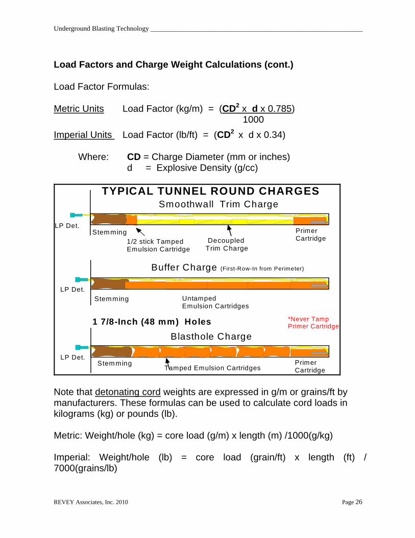
Load Factors and Charge Weight Calculations (cont.) Load Factor Formulas: Metric Units Load Factor (kg/m) = (CD2 x d x 0.785) 1000
Imperial Units Load Factor (lb/ft) = (CD2 x d x 0.34) Where: CD = Charge Diameter (mm or inches) d = Explosive Density (g/cc)
Buffer Charge (First-Row-In from Perimeter)
*Never TampPrimer Cartridge
Smoothwall Trim Charge
DecoupledTrim Charge
1/2 stick Tamped Emulsion Cartridge
LP Det.
LP Det.
Tamped Emulsion Cartridges
Blasthole Charge
LP Det.
TYPICAL TUNNEL ROUND CHARGES
1 7/8-Inch (48 mm) Holes
Stemming
Stemming
Stemming
UntampedEmulsion Cartridges
PrimerCartridge
PrimerCartridge
Note that detonating cord weights are expressed in g/m or grains/ft by manufacturers. These formulas can be used to calculate cord loads in kilograms (kg) or pounds (lb). Metric: Weight/hole (kg) = core load (g/m) x length (m) /1000(g/kg) Imperial: Weight/hole (lb) = core load (grain/ft) x length (ft) / 7000(grains/lb)

_____________________________________________Tunnels, Shaft, and Development Headings Blast Design
REVEY Associates, Inc. 2005 Page 27
TYPICAL SHAFT LOAD
Blasthole LoadSmoothwallHole Load
TampedStemming
CartridgedExplosiveLoad
Primer
Trim
Explosive
TampedStemming
Load Factors and Charge Weight Calculations (cont.) Example: Metric Given; Explosive is Pneumatically loaded ANFO density (d ) = 0.98 g/cc Charge Diameter (CD) = 40 mm -- Hole diameter Loading Factor = (402 x 0.98 x 0.785) 1000 Loading Factor = 1.23 kg/m Example: Imperial Given; Cartridged Emulsion Explosive density (d ) = 1.12 g/cc untamped Cartridge Diameter = 1.5 in. estimated Tamped Diameter = 1.7 in. = (CD) Loading Factor = (1.72 x 1.12 x 0.34) Loading Factor = 1.1 lb/ft

Underground Blasting Technology ______________________________________________________________
REVEY Associates, Inc. 2010 Page 28
Charge Weight Calculation: Charge Weight (kg or lb) = Charge Length (m or ft) x Load Factor *Use either Metric or Imperial units. Do not mix them. Example: Imperial Given; Charge length = 8 ft Loading Factor = 1.1 lb/ft Charge weight = 8 x 1.1 = 8.8 lb Example: Metric Given; Charge length = 3 m Loading Factor = 1.23 kg/m Charge Weight = 3 x 1.23 = 3.69 kg Stemming: In urban areas, stemming is usually placed in the collars of blastholes in tunnel rounds to reduce the intensity of blast-induced air-overpressure at neighboring property. Clay dummies or sand poured into tubular paper bags are tamped into hole-collars to create confining stemming. In shaft blasting, crushed stone or sand can be poured into collars to stem charges. Drilling layout for perimeter holes, lifters, and other blastholes: At this point, many factors have already influenced how many holes will be used to fill out the round. Previous design decisions have already been influenced by rock conditions, hole-size, explosive density, perimeter blasting requirements, and the type of cut used; so in effect, and as expected, they are indirectly influencing the total number of holes that will be used in the round. When the round is designed through this modular process, it becomes apparent why simple tables dictating explosive quantities based on face size are impractical.

_____________________________________________Tunnels, Shaft, and Development Headings Blast Design
REVEY Associates, Inc. 2005 Page 29
Drilling layout for perimeter holes, lifters, and other blastholes: (cont.) To facilitate the physical process of marking borehole locations on the face, it is advisable to use a systematic pattern of holes that fit into some sort of grid or concentric ring pattern. Sometimes borehole locations that are ideal from a blast sequencing perspective require modification to develop a pattern that is not too complicated to layout on the heading face.
It is important that blastholes be drilled in the right location and with right inclination (flare). Mine surveyors paint control lines and offsets on heading faces to provide references for tunnel alignment and grade. Accuracy of hole-collar placement and drilling alignment will affect hole deviation and blast results.
Perimeter Holes:
In shafts or raises, overbreak is reduced by using smoothwall blasting techniques. Perimeter holes are lightly loaded, and their spacing is tighter than regular blastholes. Typical hole-spacing for Smoothwall blasting ranges from 45 to 60cm (18 to 24 in.). In round shafts or raises the perimeter circumference = 2r or d. Where r = radius or d = diameter, and constant = 3.14. Number of holes on perimeter = circumference /smoothwall spacing Example: Metric Given; Shaft diameter (D) = 6 m Desired perimeter hole spacing = 0.5m Circumference = x D = 3.14 x 6 = 18.84 m Number of perimeter holes = 18.84 / 0.5 = 37.68 Round up to 38 holes

Underground Blasting Technology ______________________________________________________________
REVEY Associates, Inc. 2010 Page 30
CutHoles
Lifters
Buffer Holes
RibHoles
Smoothwall Arch Holes
KneeHoles
Perimeter HoleSpacing (S)
Burden (B)
SpringLine
GradeLine
LoadedCut Holes
Burn Cut Detail
Void(unloaded)Cut Holes
Perimeter Hole Look-out Angle(Just enough for drill room)
Over drillthe burncut
ExpectedBreak
Round Advance Length
Lifter CollarPipe
Cut holes
B u f fe r H o le
P e r im e te r ( b a c k ) H o le
K n e e H o le
L ifte r H o le
Room for Drill

_____________________________________________Tunnels, Shaft, and Development Headings Blast Design
REVEY Associates, Inc. 2005 Page 31
Example:
If Shaft diameter = 18 ft Desired Smoothwall Spacing = 2 ft Circumference = D (3.14 x 18) = 56.5 ft Number of Trim Holes = 56.5 / 2 28 holes
18 ft
Perimeter Hole Layout
In tunnels, smoothwall holes are not used along the tunnel floor. The smoothwall burden to spacing ratio should range from 1.5 to 2. The floor holes or "lifters" are heavily loaded and often spaced tighter than the round's regular blastholes. Rib holes above waist level may also be loaded with the normal blasthole load. Terminology for various types heading round holes is shown in the figure on page 30. To maintain the continuous cross sectional areas of tunnels and avoid tight spots, it is customary to aim perimeter holes so their toes are located some distance outside the designed perimeter. The amount of this "look-out" also depends on the physical room needed by drill head when it collars perimeter holes. Tunnel cross sectional area cannot be maintained when parallel drilling is used in perimeter holes. Lifter holes: In tunnels, the floor holes or lifters must do extra work because they usually have extra burden to break at their toes due to their downward angle. They are also covered by much of the rock that the round has already broken, greatly increasing their burden. The lifter holes are also responsible for maintaining floor grade without humps or tight spots.

Underground Blasting Technology ______________________________________________________________
REVEY Associates, Inc. 2010 Page 32
Lifter Holes: (cont.) The collar burden on lifters, measured between them and the knee holes, is often 65% to 75% of the design burden for the body of the round. It is important to recognize that the burden at the toe of lifters is generally much greater than the apparent burden at the collars, due to the hole inclination. To provide more energy for the extra work that lifters must do, an extra hole is usually drilled along the floor. To further increase the heaving output of lifter holes, they are often loaded very near to their collar. The down-looking lifter holes often contain water and their collars are often covered by rock fragments that fall off the face when other holes are drilled above them. It is a very good practice to insert short sections of PVC pipe into lifter hole collars immediately after they are drilled. These collar pipes will keep rock and other debris from entering and blocking these holes. When drilling is finished, rock and mud debris can be dug off the pipe and the intact hole can be easily loaded.
Highway Tunnel Showing scalloping effect caused by perimeter hole look-out
_____________________________________________Tunnels, Shaft, and Development Headings Blast Design
REVEY Associates, Inc. 2005 Page 33
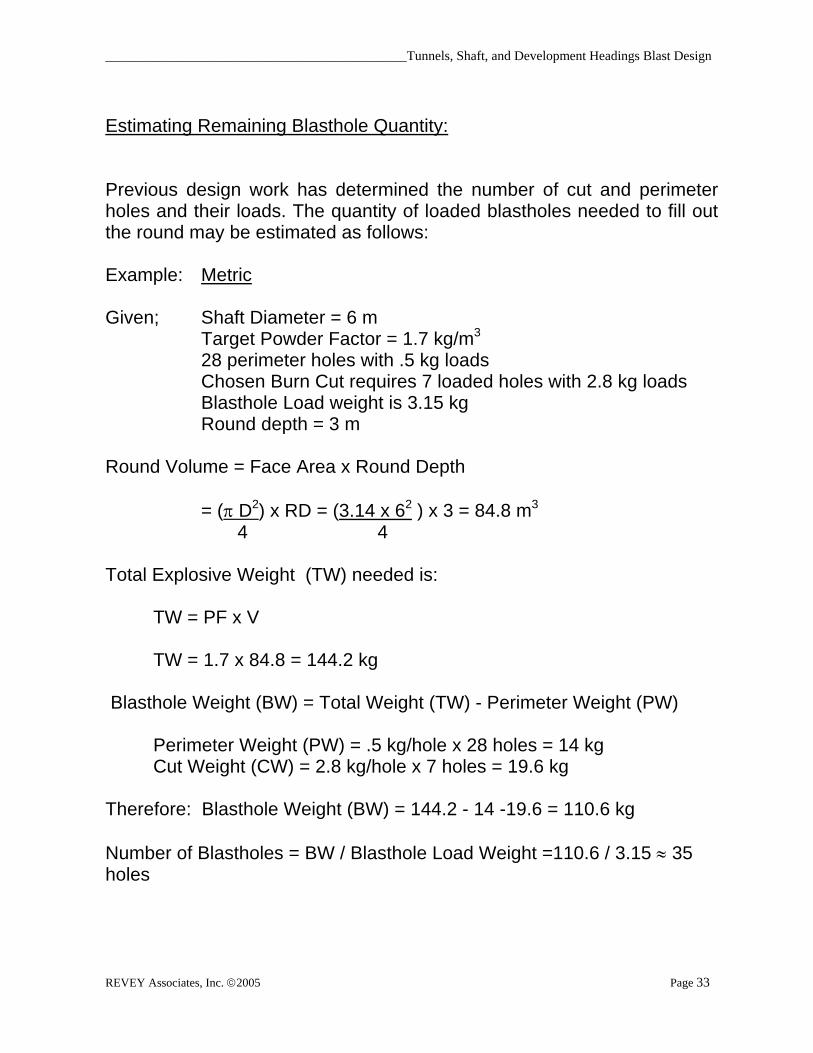
Estimating Remaining Blasthole Quantity: Previous design work has determined the number of cut and perimeter holes and their loads. The quantity of loaded blastholes needed to fill out the round may be estimated as follows: Example: Metric Given; Shaft Diameter = 6 m Target Powder Factor = 1.7 kg/m3 28 perimeter holes with .5 kg loads Chosen Burn Cut requires 7 loaded holes with 2.8 kg loads Blasthole Load weight is 3.15 kg Round depth = 3 m Round Volume = Face Area x Round Depth
= ( D2) x RD = (3.14 x 62 ) x 3 = 84.8 m3
4 4 Total Explosive Weight (TW) needed is: TW = PF x V TW = 1.7 x 84.8 = 144.2 kg Blasthole Weight (BW) = Total Weight (TW) - Perimeter Weight (PW) Perimeter Weight (PW) = .5 kg/hole x 28 holes = 14 kg Cut Weight (CW) = 2.8 kg/hole x 7 holes = 19.6 kg Therefore: Blasthole Weight (BW) = 144.2 - 14 -19.6 = 110.6 kg Number of Blastholes = BW / Blasthole Load Weight =110.6 / 3.15 35 holes
Underground Blasting Technology ______________________________________________________________
REVEY Associates, Inc. 2010 Page 34
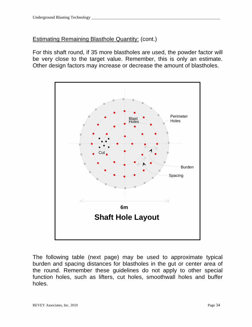
Estimating Remaining Blasthole Quantity: (cont.) For this shaft round, if 35 more blastholes are used, the powder factor will be very close to the target value. Remember, this is only an estimate. Other design factors may increase or decrease the amount of blastholes.
Shaft Hole Layout6m
Cut
PerimeterHoles
BlastHoles
Burden
Spacing
The following table (next page) may be used to approximate typical burden and spacing distances for blastholes in the gut or center area of the round. Remember these guidelines do not apply to other special function holes, such as lifters, cut holes, smoothwall holes and buffer holes.

_____________________________________________Tunnels, Shaft, and Development Headings Blast Design
REVEY Associates, Inc. 2005 Page 35
Estimating Remaining Blasthole Quantity: (cont.) These special holes should be laid out according to the requirements defined by their function. For example, lifter hole spacing is generally reduced to ensure the floor is broken cleanly and provide more gas-energy to lift and move broken rock away from the rock face. The average blasthole burdens and spacings in this table are for rocks of medium hardness. Harder or softer rocks would require smaller or greater burdens, respectively.
TYPICAL DRILL PATTERN BURDENS AND SPACINGBlasthole Diameter Maximum Burden Distance Maximum Hole Spacing
(mm) (in) (m) (ft) (m) (ft)
32 1.25 0.6 2.0 0.7 2.338 1.50 0.8 2.5 0.8 2.645 1.75 0.9 3.0 1.0 3.351 2.00 1.0 3.3 1.1 3.657 2.25 1.1 3.6 1.2 3.964 2.50 1.2 4.0 1.3 4.3
DELAY TIMING CONSIDERATIONS: Delay timing guidelines for underground rounds will vary depending on rock conditions and design restrictions. Long period delays that provide from 200 to 500 milliseconds of delay between periods are most often used in tunnel blasting. Long period detonators with inter-period delays ranging from 100 to 1,000 milliseconds are generally used in underground heading blasts. In some civil construction work, severe vibration constraints may call for the use of more than the usual number of delays, which may override the delay-timing normally used to produce good breakage. Special vibration-control round design measures are given in Section 12 - Ground Vibration and Concussion. If specific constraints do not limit delay timing options, the following general timing guidelines can be used to develop initial timing plans.

Underground Blasting Technology ______________________________________________________________
REVEY Associates, Inc. 2010 Page 36
HEADING ROUND DELAY TIMING GUIDELINES SUMMARY
1. Successive delays should be used hole-to-hole, row-to-row, and ring-to-ring wherever possible. Avoid skipping delays because the extra time will cause more prerelease failures and cut-offs. Note: special timing requirements in the bum cut, perimeter, and lifter areas of a round will supersede this general blasthole timing goal.
2. Always fire corner holes at least one delay later than all adjacent
holes. 3. In tunnel rounds, fire the lifters on or near the last delay to shear
the floor and heave the broken rock away from the face to improve digging.
Raising Excavations: Raises are developed for a variety of purposes, such as ore and waste passes, ventilation passes, and slot raises in production stopes. Conventional raise round design principles are very similar to those used for tunnels and shafts. Raises are essentially small up side down shafts. Raise design is easier in some aspects, and harder in others. Excavating raises is easier since the muck falls out, however access to raise faces is often more difficult. Of all the development headings, raise blasting is considered the most dangerous. Many serious accidents and fatalities caused by falls of ground have occurred in raise work over the years. Fortunately, raise blasting safety has been drastically improved by the development of new equipment and methods. One significant development that has improved raise access and working safety is the Alimak raise climber. It uses a rail mounted work platform to convey workers and equipment to the face. Moreover, the platform has a shield that protects miners from falls of ground.

_____________________________________________Tunnels, Shaft, and Development Headings Blast Design
REVEY Associates, Inc. 2005 Page 37
ALIMAK RAISE CLIMBER

Underground Blasting Technology ______________________________________________________________
REVEY Associates, Inc. 2010 Page 38
Drop-Raising: Several blasting technique innovations have also advanced raise blasting safety and productivity. In Canada in the early 197O's, Les Lang of CIL and INCO co-developed a mining method based on Livingston's crater theory. This method is called Vertical Crater Retreat mining (VCR) or Vertical Mining Method (VRM). An offshoot of this mining method was the development of a drop raising technique that also employed spherical crater charge technology.
VCR DROP RAISE DESIGN EXAMPLE
BurlapBag/cuttingsSeal
Wooden Block
Caristrap
4 to 5 ft.WaterStemming
1 ft.DrillCuttings
20 lbEmulsion ChubNot slitted
40 lbs.2 SlitEmulsionBags
INSIDEHOLE LOAD
PERIMETERHOLE LOAD
25 Grain Trunkline
25 Grain Downline
CastBooster
MSDetonator
1 ft.Drill Cuttings
7'
4.5'
2.5'
5.7'
3.7'
Powder Factor = 15.7 lbs/cyd with 320 lbs/round and 7 ft. advance
INITIATION HOOK-UP
1 1
2
3
4 4
3
3
3
4 4
2
Primary Iniators
25 Grain Cord
ms delay In-Hole

_____________________________________________Tunnels, Shaft, and Development Headings Blast Design
REVEY Associates, Inc. 2005 Page 39
Drop-Raising: (cont.) This and other drop raising methods have vastly improved raise blasting safety because top loading no longer requires workers to be underneath freshly blasted and dangerous ground. Miners have been refining this technique for almost 20 years and it is widely used to develop slot raises and air passes in many mines. This method is very cost effective because relatively large and few holes are required. Holes size for this application generally varies from 101 to 165 mm (4 to 6 1/2 in). This method is also very forgiving to moderate levels of hole-deviation. The disadvantages of VCR drop-raising are: 1) it generally leaves rough walls and crater charges can cause further rock damage. 2) When compared to long-hole drop-raising, VCR raises must have top loading access and they must be blasted in a series of small shots. In some mining methods, like the removal of crown pillars, the only access for developing slot raises is from the bottom. For these applications, long-hole techniques can be used to drill and shoot raises from the bottom. Long-hole raises use burn cuts to provide relief and smaller holes, ranging from 50 to 89 mm (2 to 3.5 in). Note that long-hole-raises with burn cuts can also be loaded from the top down and blasts with lengths up to 12.2 m (40 ft) have been advanced in a single blast. In bottom access drop raises, they must be completely shot in a single blast because it is unsafe to enter under them after the first blast. To a large degree, the length that these raises can be advanced depends on the accuracy of drilling, and the amount of swell room allowed in the bum cut. Improved long-hole drilling technology is continuously increasing the length that holes can be accurately drilled. Using a technique developed in Canada, several mines have successfully used a series of up to three sequentially delay decked charges to improve swell room relief and extend the length of advance. Holes in these blasts are charged with a pneumatic cartridge loader, and inert water-gel cartridges are also blown into the holes to create stemming separation between the deck loads. This technique is quite complex, and it should not be attempted without the use of electronic detonators; and expert-guided design and hole-charging practices.

Underground Blasting Technology ______________________________________________________________
REVEY Associates, Inc. 2010 Page 40
28
MS Shock tube Delays
TwoInitiators
Cordtex 25Trunkline
MS Delays Cord Clips
25 grainTrunkline
2824
24
2020
12 12
16 16
8 8
5 1
3 5
6.5'
8'
5" Open Hole
3" Blasthole
Typical Long-Hole Drop Raise Drilling and Timing Design
Long Hole Drop Raise Loading Scheme
Suspended1 3/4" Wood Dowel
Baggie and Cuttings 1.5'
MSDelays
Cast Boosters
ANFO/polystyreneCharge
7'
Collar Stick
1'Clean SandStemming
_____________________________________________Tunnels, Shaft, and Development Headings Blast Design
REVEY Associates, Inc. 2005 Page 41
Controlled Blasting Techniques: Three techniques commonly used to control overbreak in tunnels and other heading rounds are: 1. Line Drilling 2. Pre-splitting 3. Smoothwall Blasting Line Drilling: In this technique, very tightly spaced holes are drilled along a controlled break line. By introducing this void space the gases and stresses from nearby blastholes are vented and attenuated respectively. Line drilling is a very effective overbreak control method but extensive drilling requirements make it very costly. This method is used only in very critical blasting situations, such as portal entry blasts where every effort is made to minimize damage in the portal brow. that can be used to limit overbreak and final rock wall damage in excavations that use either blasting or mechanical methods for mass rock removal. The row of holes adjacent to the line drilling is carefully spaced and lightly loaded. The objective is to have it break back to the line drilled perimeter, but not beyond. Line drill holes are not normally blasted, however if necessary, light charges can be put in them to trim off tight spots left by the main blast. Pre-splitting: Rock planes can be “pre-split” by blasting lightly loaded and closely spaced holes drilled along excavation boundaries. The sheared perimeter creates an excavation break limit that minimizes overbreak and final wall damage. With this technique, very lightly loaded normally de-coupled charges, are loaded and fired instantly, or with minimum delays between groups of perimeter holes. In underground excavations, pre-splitting has been effectively used to shear vertical perimeter walls of bench rounds in room-and-pillar mining operations. However; pre-splitting methods should never be used in underground tunnel, shaft and cavern blasts because excessive overbreak and rock damage almost always occurs when excavations have corners and/or curved perimeter shapes.

Underground Blasting Technology ______________________________________________________________
REVEY Associates, Inc. 2010 Page 42
LINE DRILLING FOR OVERBREAK CONTROLHole Spacing
ControlledBreak Plane
.ightly SpacedOpen Holes
Final Excavation Line
PRE-SPLIT BLASTINGFOR OVERBREAK CONTROL
Final Excavation Line
Hole SpacingControlled
Break PlaneSub Drilling
Stemming
BottomCharge (Primer)
ContinuousDe-coupledLoad

_____________________________________________Tunnels, Shaft, and Development Headings Blast Design
REVEY Associates, Inc. 2005 Page 43
Smoothwall Blasting: This method of overbreak control is widely used because it produces good results at reasonable cost. When smoothwall blasting is done, lightly loaded perimeter holes, firing on the last or near last delay, are designed to slash off the last row of rock against the final perimeter of the round. The goal is to load these holes just heavy enough whereby they break off the last row of rock with minimal damage to the remaining ground. Much research and practical experience has shown that smoothwall blasting works best when the burden on the perimeter holes is greater than the spacing. Results are also improved when smoothwall charges are properly secured in the hole by using some type of collar plug. In most ground, blastholes should never be closer than two feet from perimeter holes and the burden/spacing ratio should be at least 1.5 or greater. In weak ground, results will improve if this ratio is 2 or higher. In weak or loosely jointed rock, reflected tension loads from heavily loaded blastholes firing near the final perimeter can cause damage rock in tunnel backs and walls. The tensile stress caused by these reflected waves can be reduced by increasing the amount of burden on the trim and buffer row holes. In other words, move them farther away from the final perimeter. Smoothwall Delay Timing: When ground is very poor, or severely jointed, the smoothwall perimeter charges should be fired together with a common delay, after all other adjacent holes have fired. This is done to minimize charge cut-offs occurring when earlier firing holes in the perimeter damage the ground holding adjacent charges. Very light charges should also be used when ground is weak. In more competent ground, results seem to improve when more delays are used. Holes are typically fired in groups of two or three, with corner holes always firing last.

Underground Blasting Technology ______________________________________________________________
REVEY Associates, Inc. 2010 Page 44
Smoothwall Holeson 18 to 24" Centers
BufferHoles
899
11
1111 11
11
12 12
1313
13 13
1332 to 36 in.
BlastHoles
GENERAL SMOOTHWALL BLASTING SCHEME FOR METRO RAIL TUNNELS
Buffer Load
Blasthole Load
Untamped Cartridges
TampLast Stick
18" 12"
Tamped 12"
Subdrill
Subdrill
Smoothwall Load
24"12"
Subdrill
200 grain Cordtaped to PrimerCartridge
1/2 sticktamped toplug hole
24"
LP Det.
14
131313
14
121212
Cartridges
LP Det.
LP Det.

_____________________________________________Tunnels, Shaft, and Development Headings Blast Design
REVEY Associates, Inc. 2005 Page 45
Smoothwall Blast Charges: High strength detonating cords or special trim blasting explosives are typically used to produce the light loads necessary for successful smoothwall blasting. Dynamite, packaged in two foot cartridges, with linear charging densities between 0.37 and 0.50 kg/m (0.25 and 0.34 lb/ft) is made for this application. Before loading, these dynamite sticks are coupled together with special plastic couplers that are shipped with the product. These narrow decoupled charges are often traced with detonating cord that is taped or half-hitched to the cartridges to ensure complete detonation. Detonating cords with 200 or 400 grains of PETN per foot are also used to create light decoupled smoothwall charges. When used, a cut length of cord is taped to the primer, and loaded as a trailing tail behind the primer stick as it is pushed to the borehole toe with a loading pole. For both load types, a regular size high explosive primer cartridge is usually placed in the toe of the hole to effectively prime the light column and minimize boot-legs at the borehole toe. Controlled Blasting Case History: Two drill-blast variations, designed to minimize overbreak, were evaluated in the Halawa side of the H3 Highway tunnels in Hawaii. The first method used blasting, followed by mechanical trimming with a road header. The second alternative was conventional Smoothwall blasting. A review of the two techniques follows. Method 1.) Conventional drilling and blasting combined with mechanical excavation Rock was drilled and blasted to within one foot of the final perimeter. The final foot of rock was then trimmed off with a backhoe mounted roadheader. Figure 3 illustrates this general design technique, specific to the center drift section. Note that the row of holes adjacent to the final perimeter used a lighter "buffer" load to reduce back-break into the roadheader trim area. This lighter charge was achieved by loading an untamped column of semi-gelatin dynamite. Only the last stick loaded was tamped to hold the charge in place.

Underground Blasting Technology ______________________________________________________________
REVEY Associates, Inc. 2010 Page 46
Method 1.) Conventional drilling and blasting combined with mechanical excavation (cont.) The untamped dynamite loaded at 1.5 kg/m (0.98 lb/ft) versus 1.7 kg/m (1.12 lb/ft) when tamped. Design-wise, it might have been preferable to use a lower strength explosive in the buffer holes; however, most tunnel workers prefer handling only one explosive type. An untamped-light load was a practical alternative. Worker preference and experience also influenced drill-blast designs that were often modified to suit changing ground conditions. These rounds provided good fragmentation and muck displacement. The break along the buffer row was fairly even with no more than 8 inches of back-break. The road-header trimmed off the final foot of rock. However, after operating for only a few days, the road header attachment failed and this method was abandoned.
Center Top Heading with Roadheader Trim
Buffer Load
Blasthole Load
Untamped TampLast Stick
18" 12"
Tamped Semi-gelatinDynamite
12"
Subdrill
Subdrill
12"
3
77
1
1 2
23
4
45
5
5
5
6
67 7
8
8 8
8
8
9
9 9
9 9
910
10
10
10
10
10
12 12
11
15 14 14 14 1514 14 14 14
11
10 10
1'
Roadheader Trim Area
LP Delays
Buffer Holes
11 1111 11
11
Semi-gelatinDynamite
Method 2) Conventional smoothwall blasting

_____________________________________________Tunnels, Shaft, and Development Headings Blast Design
REVEY Associates, Inc. 2005 Page 47
This method, applied to the same center drift round, is shown in the figure below. Trim holes, spaced 46 cm (18 in) apart, were loaded with semi-gel trim dynamite in 22 x 600 mm (7/8 in x 24 in) sticks and primed a single stick of 32 x 400 mm ( 1 ¼ x 16 in) semi-gel dynamite. In the initial smoothwall rounds, the trim row burden of 0.76 m (2.5 ft) gave a burden to spacing (B/S) ratio of 1.7 (.76/.46) or (2.5/1.5) which is higher than the more common limit of 1.5. Very poor Halawa ground conditions necessitated this variance to prevent the buffer detonations from damaging the trim charges. In later rounds, the burden was increased to 0.9 m (3 ft), which gave a B/S ratio of 2. To further minimize smoothwall charge damage, the buffer charges were lightened by loading un-tamped semi-gelatin dynamite cartridges. These smoothwall rounds provided good fragmentation and muck displacement. The Caterpillar 980--4 cubic yard loader easily handled the muck produced by the relatively large smoothwall burdens. The usually crumbly ground broke up very well when the trim charges knocked it down. The neat-line break was fairly clean with minimal overbreak. Where tights did occur, they were easily removed by the road-header. The powder factor for the center drift rounds averaged 2.5-kg/m3 (4.2 lb/yd2). The bench and slash round powder factors were much lower -- ranging from 1.07 to 1.5 kg/m3 (1.8 to 2.5 lb/yd2). CONCLUSIONS 1. Both methods used to control overbreak in the Halawa Tunnels were effective. But, as the job progressed, the contractor opted to use the smoothwall Method because schedule changes limited the time available for road-header trimming. 2. The backhoe-mounted road-header trimming of tights was more efficient, and caused less overbreak than the drill-blast method. 3. In soft ground, the Smoothwall burden to spacing (B/S) ratio should be increased above the conventional 1.5 limit generally used in hard rock. In the Halawa tunnels, smoothwall burdens ranged from 0.76 to 0.9 m (2.5 to 3 ft). Trim-hole-spacing varied from 0.5 to 0.6 (1.5 to 2 ft). The average B/S ratio in the Halawa smoothwall blasts was 1.7.

Underground Blasting Technology ______________________________________________________________
REVEY Associates, Inc. 2010 Page 48
Center Top Heading with Smoothwall Blasting
Smoothwall Holeson 46 cm(18 in) Centers
BufferHoles
3
77
1
1 2
23
4
45
5
5
5
6
67 7
8
8 8
8
8
9
99
99
910
10
10
10
10
10
11
1111 11
11
12 12
1514
14 14 13 13 1313 14
13
1414
15
75 cm(30 in)
11
16 15 15 16
11
Buffer Load
Blasthole Load
Untamped Dynamite
TampLast Stick
46 cm (18 in)
Tamped Dynamite
Smoothwall Load
61 cm (24 in)
30.5 cm(12 in)
Subdrill
1/2 Stickplug
Trim Powder & 5 g/m (25 gr)Det Cord
1 Stick Primer
61 cm (24 in)
Primeris bevertamped15 15 15 15 15