turbine design - ترجمه فاtarjomefa.com/wp-content/uploads/2016/09/5403-english.pdf · blades...
TRANSCRIPT

Turbine Design
Abstract
Big water turbines are some of the machines that produce power and we can use
computational fluid dynamics method to design and analyze them. Nowadays
considering finances and also the need of energy in industries, using the whole potential
of a source and getting the most possible energy out of it is considered something
important. After many years of experimenting and experiencing different turbines and
considering the head and fluid rate based on increasing specific speed, the turbine type
for the best performance are respectively impulse turbines, radial turbines, mixed flow
turbines, and at last axial turbines. For heads lower than 5.4 meters, turbines (very
low head)1 are used which besides their working conditions, we must consider their
environmental effects and the development plans, and also having in mind that they are
installed on rivers. In this research first we extract geometrical data regarding the head,
output power and desired efficiency and then it will be designed using Solidworks
software and then using numerical analysis in ansys cfx software, we determine the
accuracy of produced geometry. After reaching the desired geometry, cross section of
blades made of NACA standard airfoil which are two dimensional airfoils will be
created. Initial designed geometry of the head is 2 meters, the power is 190 KW and
efficiency is 90%. Also any change in geometrical parameters like Stagger angle (which
determines the blade rotation) and external diameter and their effects on turbine
performance are studied.
Keywords: VLH Turbine, Very Low Head, Design, Airfoil, Stagger Angle
Very Low Head(VLH) -1
Preface
Advances and developments of a country are critically dependant on power industry. So
paying attention to power industry as one of the infrastructure services in a country is
very important. World wide statistics show an increase in demand to use electricity.
Currently because of increasing oil price in the world and current situation of our area,
the importance of hydroelectric power as a clean energy has increased. Attention and
investment in hydroelectric power plants can help economical development, and also play a
major role in energy development too. Today about one-fifth of produced electricity in the
world is from hydroelectric turbines. This kind of turbine has the lowest pollution and a high
efficiency (up to about 95%). The most common types are Pelton, Francis and Kaplan [25].
Water potential since old times has been one of the noteworthy energy sources. Today
with the significant growth in industry, the need to this energy has increased. In
addition, all big industries use electrical power in their machinery and tools. Knowing
that electrical energy mainly is produced from fossil fuels which are irreplaceable
sources, and the environmental problems that are caused by these sources, has increased
enthusiasm in using water turbines to produce electricity. On the other hand, limited
water potential and also the cost of power plant construction and delivering the electricity
from the plant to consumers has made people turn to local power production in smaller scales.
Using small water turbines can be a solution to achieve this goal. First step in designing turbine
wheels is to determine the original dimensions which in addition to showing total geometry and
size of the turbine, will give a cost estimation of mechanical and structural devices which are
needed. Entry and exit diameters of the design and also the blade profile from hub to tip are

some of the most important dimensions of Francis turbine wheel. To determine the geometry of
the wheel first these dimensions are specified, and then total solitary shape of the wheel is
determined and the layout of the blade will be given. Next this layout will be the base to fully
design the blade profile.
Energy conversion depends on all different parts of turbine consisting of runner, fixed
and moving blades, and wheel. Yet it’s the turbine wheel which has a primary role. The
wheel blades design is important in energy conversion and it must be designed as good
as possible. Although in designing turbines, study of distributor parts is important,
knowing primary characteristics of the wheel is the most important part of the study.
Determining dimensions in old turbines were done using hydraulic calculations and trial
and error method, and then necessary corrections were made in order to optimize the
design. Today main dimensions are extracted based on experimental relations from
working turbines, and then necessary changes will be made to achieve intended results.
So because of different methods of determining the dimensions, different producers use
different sizes and forms of turbines even if they have the same application. The number
of unknown parameters in designing turbines is bigger than the number of known
parameters, and two quantities of height and flow will give many choices for the design
and each design has a primary role in efficiency and output, so we can say that design
process can not be unique. Different methods have common concepts and basically their
difference is because of the experiences that the design is based on.
Water turbines are normally big systems and they’re designed for specific conditions.
So they can’t be mass produced. If these systems are only tested after their production,
then:
- Performing many testes on prototypes would be expensive and time consuming.

- Changing dimensions and turbine size, if test results don’t match the analysis data,
would be very expensive.
- Also prototype tests, have limits like impossibility of changing the head, the need to
apply static speed to the system, possibility of unstable available load based on correct
and precise situation [21].
Because of the reasons mentioned, doing model tests is a definite necessity in order to
predict the main system behavior. These tests have relatively low costs, acceptable
accuracy and ease, and they’re widely and comprehensively achievable and their results
can be extended to the main model using dynamic similarities.
It must be considered that in some cases in which there are many dimensionless
parameters, it would be very difficult to make the system and the model completely
similar. Because it’s necessary that many dimensionless parameters become equal
simultaneously.
In this case, usually they remove some of the dimensionless parameters which have
little effect on the results and only important dimensionless parameters are analyzed.
Then they study the effects of removed parameters using theories or separate
experiments.
Not involving Reynolds effects in relations regarding the behavior and the performance of
turbo machines gives a relatively good estimation; because Reynolds number in most turbo
machines is relatively high and the flow is completely disarranged. So changes in friction
coefficient as a result of changes in Reynolds number are insignificant. Despite this, to study
turbo machines behavior more exactly and to calculate their efficiency it’s necessary to consider
changes in Reynolds number. In cases of high changes in Reynolds number (as in comparison
between model and prototype, which because of big changes in dimensions and fluid velocity,
Reynolds number can be very different), the efficiency can have relatively big changes and so
Reynolds changes must be checked. There are many relations in order to calculate efficiency
changes in turbo machines as a result of friction and we will mention some of them in next
chapters. On the other hand using numerical analysis of full geometry can significantly help us
avoid expensive and time-consuming tests.
In the past, different parts of turbines were studies separately; and there can be many reasons for
this separate analysis of different parts of a turbine. First, for some time the codes were not able
to solve two fixed and moving parts simultaneously; but now this problem is solved and we can
solve the flow of rotating and non-rotating parts simultaneously. Second, it’s because of limited
capacity of computer in solving the full geometry simultaneously; and despite science advances,
this issue still exists. There is no doubt that there is great benefit in simultaneously solving
rotor, stator and suction pipe because this will avoid applying non-exact boundary conditions on
every separately solving part [19].
Because of very small heights in lateral structure of many rivers, they can’t be used to produce
energy. So VLH turbines are used in order to produce hydroelectric energy in such places.
VLH turbine has standard impeller diameter of 3.15 - 5.0 meters. The maximum water that the
turbine can store is between 8.2 m3 to 27.1 m3.
Because of VLH turbines being submerged, they have very little noise and they have very small
effects on the environment around them. Also because of placing these turbines in rivers, the
location of their equipments would be near urban areas and these areas wouldn’t be inaccessible
[21].
It’s obvious that despite small height for falling water, if the required water flow is
achieved by a suitable structure, using water turbines to produce electricity would be
possible. But using contemporary common turbines in such conditions require
infrastructures to produce this water flow and because of high costs of construction
research, practically using common turbines is not beneficial.

So practically what’s important is to use the turbine which we don’t need significant
infrastructures for it. In recent decade fluid dynamics method has been used to design
many turbines and energy conversion systems. This method has been used in modeling
Viscous flow around blades. Every method has its own accuracy and costs. To simulate
computational fluid dynamics model we could use a software like Ansys CFX.
If turbine design data are as below, then we would have:
Considering these calculations and given steps above, full data for each
section would be as the table below:
Solidity
Mach
6Re*10
/L D
stagger
Chord
2 1 r
1.0500 0.0039 1.8372 9.75 16.96 0.329 51.2
8 58.2
4
-
32.1
6 0.399 1
1.0773 0.0035 2.0073 12.3 24.36 0.4089 45.8
5
53.1
5
-
15.6
8
0.483
3 2
1.0909 0.0033 2.2486 14.68 30.67 0.4754 41.9 49.3 -2.1 0.554
9 3
1.1045 0.0034 2.5647 16.95 35.71 0.5363 38.8
4
46.2
1 8.73
0.618
2 4
1.1182 0.0035 2.9374 19.15 39.61 0.5934 36.3
8
43.6
6
17.2
8
0.675
7 5
1.1318 0.0036 3.3530 21.29 42.63 0.6477 34.341.524.00.7286

4 1 7 6
1.1455 0.0038 3.8021 23.38 44.97 0.6999 32.6
1
39.6
6
29.5
3
0.777
9 7
1.1591 0.0040 4.2786 25.44 46.82 0.7504 31.1
2
38.0
3 34
0.824
3 8
1.1727 0.0042 4.7781 27.47 48.3 0.7997 29.8
3 36.6
37.7
1
0.868
2 9
1.1864 0.0044 5.2977 29.47 49.51 0.8479 28.6
8
35.3
2
40.8
4 0.910
1
0
1.2000 0.0046 5.8354 31.45 50.49 0.8954 27.6
5 34.1
7 43.5
1 0.950
1
1
Table 3-1 design data of turbine sections
To make it easy to create a 3D geometry and to decrease the number of
sections to be drawn, the design would be done in 4 sections as below:
Solidity
Mach
6Re*10
/L D
stagger
Chord
2 1 r
1.0500 0.0039 1.8373 9.75 16.96 0.3290 51.2
9 58.2
5 -32.16
0.399
0 1
1.1250 0.0034 2.7919 17.69
1 37.12 0.5637
37.9
6
45.3
1
11.80
6
0.637
9 2
1.1625 0.0040 4.1454 24.76 46.25 0.7388 31.6
0
38.5
5
32.60
5
0.809
2 3
1.2000 0.0046 5.8354 31.45 50.49 0.8954 27.6
5 34.1
7 43.51
0.950
0 4
Table 3-2 design data for decreased sections of turbine.
Drawing blade sections
Several standard airfoils with different numbers and widths were studied and analyzed
and at last they were chosen respectively as NACA4404, NACA4405, NACA4407 and

NACA4412 sections considering NACA width and chord length of each section. Data
for each airfoil was extracted from XFoil software, and after creating Stagger angle for
the section, it will be used in Solidworks software to create 3D geometry. Below you
see some steps of designing a 3D turbine blade:
Figure 3-9 airfoils placed with desired Stagger angle and chord length and their
position in relation to rotation axis.
Figure 3-10 creating 3D blade geometry.
Figure 3-11 complete turbine rotor with 8 blades.

Figure 3-12 entry runner blades.
Figure 3-13 runner blades and their position in relation to fixed turbine chamber.
Numerical analysis and results
Software analysis
Due to current limitations in software analysis of the designed turbine, only one turbine
blade with its flow direction is simulated and different conditions will be applied
periodically to this blade and its surrounding geometry. This geometry is shown in the
figure below:

Figure 4-1 one-blade view and periodic conditions.
Producing mesh and its related settings
After creating intended geometry, it will be analyzed in Ansys15-CFX software. In the
next sections we will see the produced mesh on the geometry and its settings:

Figure 4-2 the produced mesh and its settings.
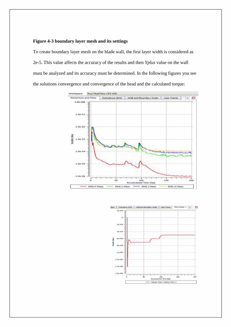
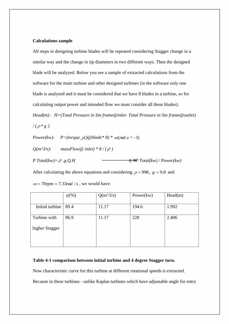
Figure 4-3 boundary layer mesh and its settings
To create boundary layer mesh on the blade wall, the first layer width is considered as
2e-5. This value affects the accuracy of the results and then Yplus value on the wall
must be analyzed and its accuracy must be determined. In the following figures you see
the solutions convergence and convergence of the head and the calculated torque:
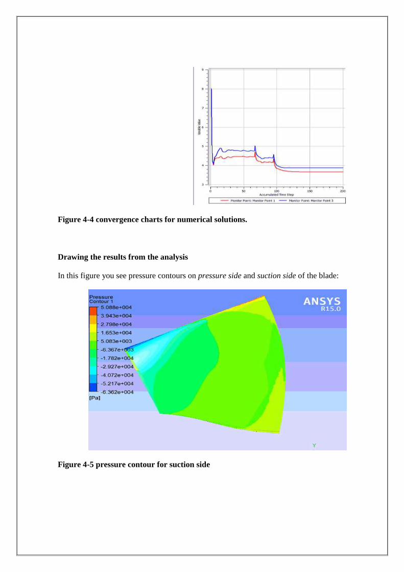
Figure 4-4 convergence charts for numerical solutions.
Drawing the results from the analysis
In this figure you see pressure contours on pressure side and suction side of the blade:
Figure 4-5 pressure contour for suction side
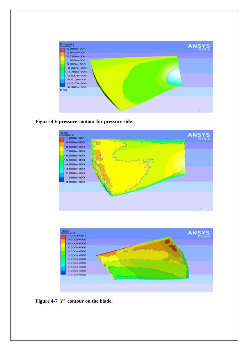
Figure 4-6 pressure contour for pressure side
Figure 4-7 contour on the blade.
Calculations sample
All steps in designing turbine blades will be repeated considering Stagger change in a
similar way and the change in tip diameters in two different ways. Then the designed
blade will be analyzed. Below you see a sample of extracted calculations from the
software for the main turbine and other designed turbines (in the software only one
blade is analyzed and it must be considered that we have 8 blades in a turbine, so for
calculating output power and intended flow we must consider all these blades):
Head(m): H=(Total Pressure in Stn frame@inlet- Total Pressure in Stn frame@outlet)
/ ( *g )
Power(kw): P=(torque_y()@blade* 8) * ( . ^ 1)rad s
Q(m^3/s): massFlow@ inlet) * 8 / ( )
P Total(kw)= .g.Q.H =P Total(kw) / Power(kw)
After calculating the above equations and considering 998 , 9.8g and
70 7.33 /rpm rad s , we would have:
Head(m) Power(kw) Q(m^3/s) (%)
1.992 194.6 11.17 89.4 Initial turbine
2.406 228 11.17
86.9 Turbine with
higher Stagger
Table 4-1 comparison between initial turbine and 4 degree Stagger turn.
Now characteristic curve for this turbine at different rotational speeds is extracted.
Because in these turbines - unlike Kaplan turbines which have adjustable angle for entry
runner blades – angle of incidence for entry runner blades is fixed, synchronous
equipments are used in these turbines in order to connect to electricity network and the
rotational speed can change. In the following sections these charts are shown:
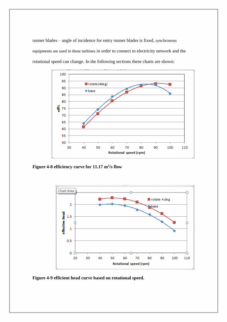
Figure 4-8 efficiency curve for 11.17 m3/s flow
Figure 4-9 efficient head curve based on rotational speed.
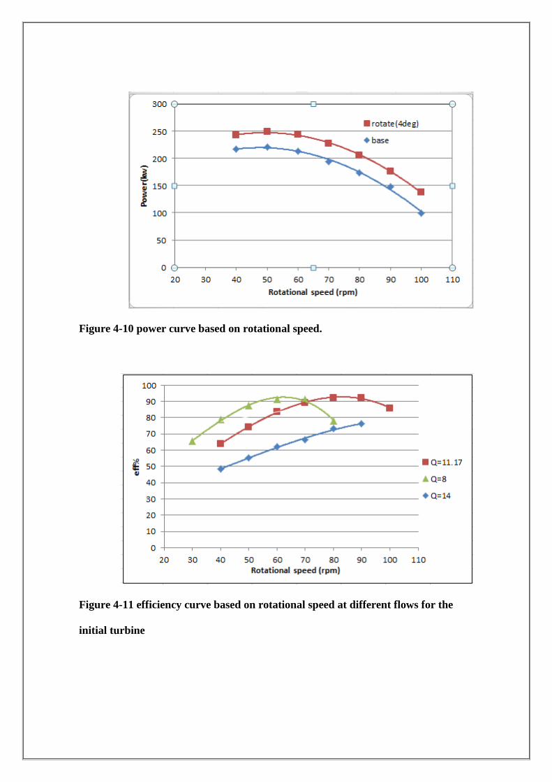
Figure 4-10 power curve based on rotational speed.
Figure 4-11 efficiency curve based on rotational speed at different flows for the
initial turbine
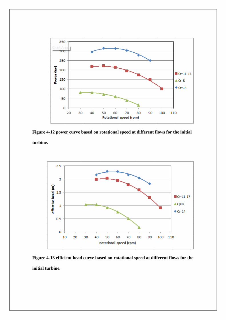
Figure 4-12 power curve based on rotational speed at different flows for the initial
turbine.
Figure 4-13 efficient head curve based on rotational speed at different flows for the
initial turbine.
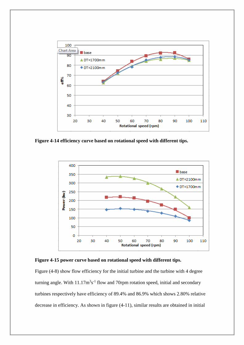
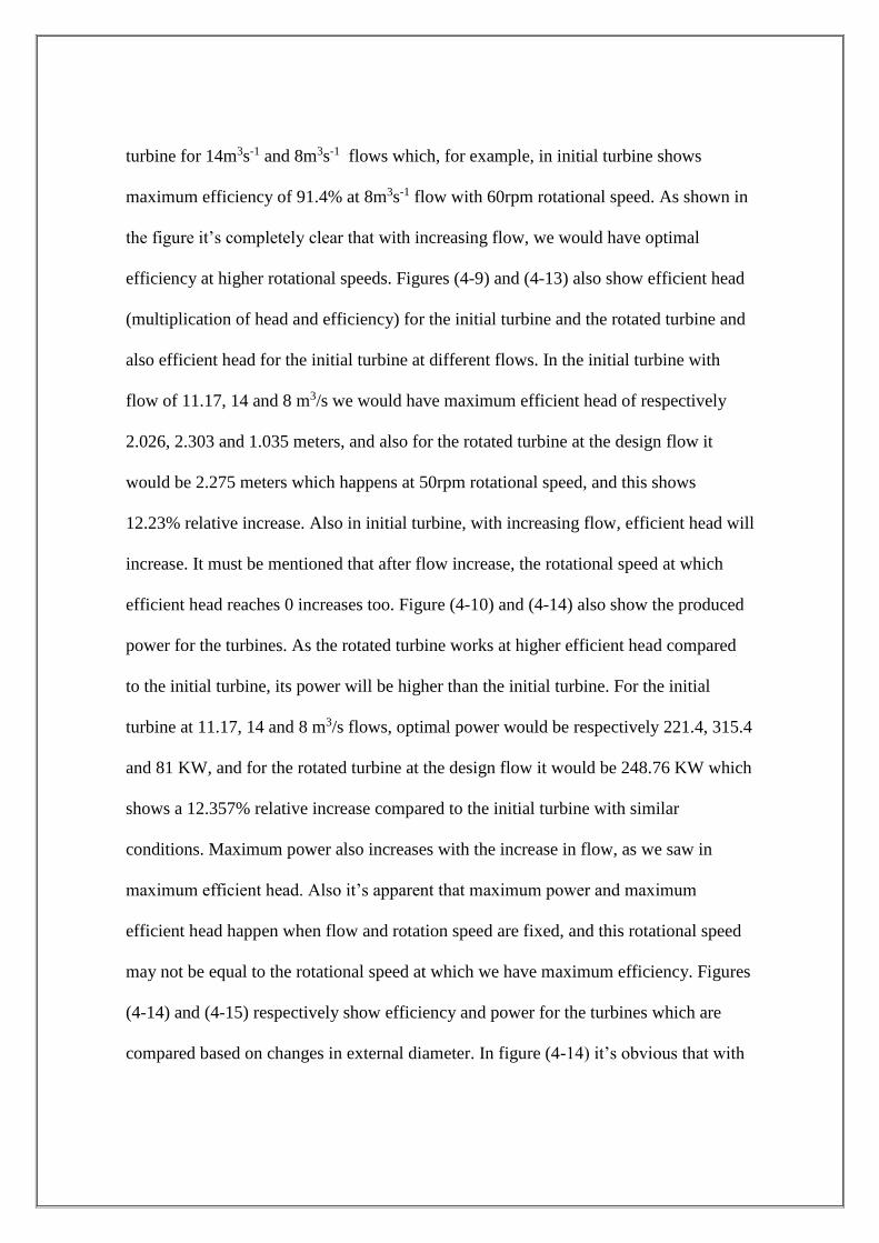
Figure 4-14 efficiency curve based on rotational speed with different tips.
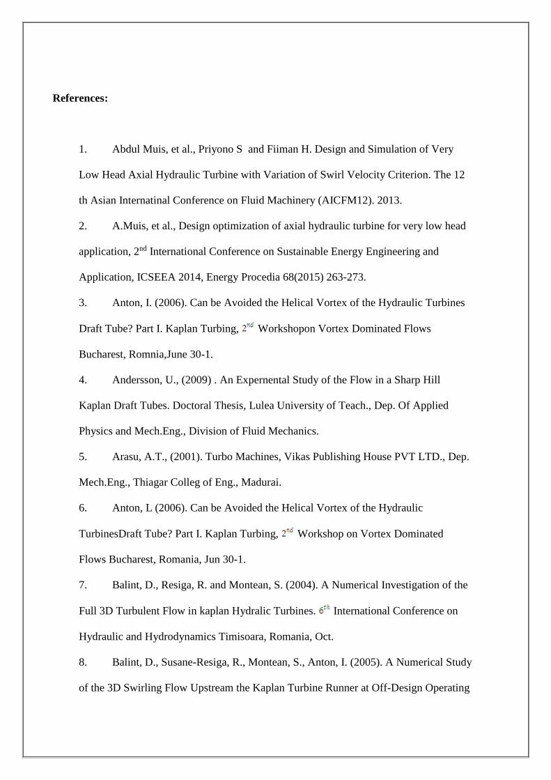
Figure 4-15 power curve based on rotational speed with different tips.
Figure (4-8) show flow efficiency for the initial turbine and the turbine with 4 degree
turning angle. With 11.17m3s-1 flow and 70rpm rotation speed, initial and secondary
turbines respectively have efficiency of 89.4% and 86.9% which shows 2.80% relative
decrease in efficiency. As shown in figure (4-11), similar results are obtained in initial
turbine for 14m3s-1 and 8m3s-1 flows which, for example, in initial turbine shows
maximum efficiency of 91.4% at 8m3s-1 flow with 60rpm rotational speed. As shown in
the figure it’s completely clear that with increasing flow, we would have optimal
efficiency at higher rotational speeds. Figures (4-9) and (4-13) also show efficient head
(multiplication of head and efficiency) for the initial turbine and the rotated turbine and
also efficient head for the initial turbine at different flows. In the initial turbine with
flow of 11.17, 14 and 8 m3/s we would have maximum efficient head of respectively
2.026, 2.303 and 1.035 meters, and also for the rotated turbine at the design flow it
would be 2.275 meters which happens at 50rpm rotational speed, and this shows
12.23% relative increase. Also in initial turbine, with increasing flow, efficient head will
increase. It must be mentioned that after flow increase, the rotational speed at which
efficient head reaches 0 increases too. Figure (4-10) and (4-14) also show the produced
power for the turbines. As the rotated turbine works at higher efficient head compared
to the initial turbine, its power will be higher than the initial turbine. For the initial
turbine at 11.17, 14 and 8 m3/s flows, optimal power would be respectively 221.4, 315.4
and 81 KW, and for the rotated turbine at the design flow it would be 248.76 KW which
shows a 12.357% relative increase compared to the initial turbine with similar
conditions. Maximum power also increases with the increase in flow, as we saw in
maximum efficient head. Also it’s apparent that maximum power and maximum
efficient head happen when flow and rotation speed are fixed, and this rotational speed
may not be equal to the rotational speed at which we have maximum efficiency. Figures
(4-14) and (4-15) respectively show efficiency and power for the turbines which are
compared based on changes in external diameter. In figure (4-14) it’s obvious that with

changes in tip, maximum efficiency decreases but considering figure (4-15) we can
show that with increasing tip, we would acquire higher power.
conclusion

Based on the extracted charts and the result, we can see that:
With an increase of Stagger angle in the design, efficient head and output power
increase;
With an increase of Stagger angle in the design, efficiency is lowered and
maximum efficiency happens at higher rotational speed;
With a decrease of flow, the maximum efficiency point will move to the left
side;
Always with a specific tip diameter, we would have the best performance and
the design must be edited to achieve this number;
With an increased change of the flow, the efficiency would be lower than the
design;
With increasing flow, the efficient head of the turbine would increase;
With increasing the tip diameter, power and efficient head increase.
References:
1. Abdul Muis, et al., Priyono S and Fiiman H. Design and Simulation of Very
Low Head Axial Hydraulic Turbine with Variation of Swirl Velocity Criterion. The 12
th Asian Internatinal Conference on Fluid Machinery (AICFM12). 2013.
2. A.Muis, et al., Design optimization of axial hydraulic turbine for very low head
application, 2nd International Conference on Sustainable Energy Engineering and
Application, ICSEEA 2014, Energy Procedia 68(2015) 263-273.
3. Anton, I. (2006). Can be Avoided the Helical Vortex of the Hydraulic Turbines
Draft Tube? Part I. Kaplan Turbing, Workshopon Vortex Dominated Flows
Bucharest, Romnia,June 30-1.
4. Andersson, U., (2009) . An Expernental Study of the Flow in a Sharp Hill
Kaplan Draft Tubes. Doctoral Thesis, Lulea University of Teach., Dep. Of Applied
Physics and Mech.Eng., Division of Fluid Mechanics.
5. Arasu, A.T., (2001). Turbo Machines, Vikas Publishing House PVT LTD., Dep.
Mech.Eng., Thiagar Colleg of Eng., Madurai.
6. Anton, L (2006). Can be Avoided the Helical Vortex of the Hydraulic
TurbinesDraft Tube? Part I. Kaplan Turbing, Workshop on Vortex Dominated
Flows Bucharest, Romania, Jun 30-1.
7. Balint, D., Resiga, R. and Montean, S. (2004). A Numerical Investigation of the
Full 3D Turbulent Flow in kaplan Hydralic Turbines. International Conference on
Hydraulic and Hydrodynamics Timisoara, Romania, Oct.
8. Balint, D., Susane-Resiga, R., Montean, S., Anton, I. (2005). A Numerical Study
of the 3D Swirling Flow Upstream the Kaplan Turbine Runner at Off-Design Operating
Conditions. Workshop on Vortex Dominated Flows-Achievements and Open Problems
Timisoara, Romania, June 10-11.
9. Bansal, R.K., (1998). A Text book of Fluid Machines and Hydraulic Machines.
LAXMI Publication (p) LTD, New Delhi.
10. Djelic, V., Kercan, V., Vujunic, V. (2000). Efficiency Scale-up in
RefurbishedLow Head Kapian Turbines, the IHAR Symposium, Charlotte, USA,
August 6-9.
11. Fay, A. (2004). The Prenciple of Neglecting Upstream Reactions. The
International Conference on Hydraulic Machinery and Hydrodynamics. Timisoara,
Romania, Oct.
12. FLUENT 6.3 Documentation.
13. Gagnon, J-M., Deschenes, C., Ciocan, G.D., Iliescu, M. (2008). Numerical
Simulation and Experimental Investigation of the Flow in an Axial Turbine. IAHR 24
TH Symposium on Hydraulic Machinery and Systems, Oct 27-31.
14. Geberkiden, B.M. (2009), Experimental and Numerical Investigation of Axial
Turbine Models. Licentiate Thesis, Lulea University of Teach., Dep. Of Applied
Physics and Mech. Eng., Division of Fluid Mechanics.
15. Gyllenram, W. (2008). Analytical and Numerical Studies of Internal Swirting
Flows. Thesis for the Doctor of Philosophy in Thermo and Dynamic, Chalmers Uni. Of
Tech, Goteborg, Sweden, 2008.
16. Hothersall R. (2004). Hyrodynamic design guide for small Francis andPropeller
Turbines. United Nation Industrial Development Org., Veena, Austria.
17. Ida, T., Kurokawa, Tanaka, H., (1996), Recent Development of Studies on Scale
Effect Hydraulic Machinery and Cavitation , Kluwer Academic Publishers, Printed in
Netherlands.
18. Isbasoiu, E., Constantinescu, M., Otomega, D., Safta, C., Neagoie, c., Ghergu,
C. (2004). Indirect Method to Calculate the Operating Flow on a Kaplan turbine.The
International Conference on Hydraulic Machinary and Hydrodynamics, Timisoara,
Romania, Oct.
19. Jost, D., lipej, A., Sirok , B. (1998). Comparision between Results of the
Components and Complete Turbine CFD Simulation, J. Hydropower
Dams.0952264277.
20. Karlsson, M., Nilsson, H. and Aidanpaa, J-O. (2008). Influnce of Inlet boundary
conditions in the prediction of rotor dynamic forces and moments for a hydraulic
turbine using CFD. The International Symposium on Transport Phenomena and
Dynamics of Rotating Machinery Honolulu, Hawaii, Feb. 17-22.
21. Lal, J. (1998). Hydraulic Machines, ed., Metropoliten Book Co., Netaji
Subhash Marg, NEW DELHI.
22. Liu, sh., Li, sh, Wu, Y. (2009). Pressure Fluctuation Prediction of a Model
Kaplan Turbine by Unsteady Turbulent Flow Simulation, J. Fluid Engineering. Vol.
131/101102-1.
23. Marjavaara, B.D., etal (2003). Automatic Shape Optimization of a Hydropower
Draft Tube, ASME _JSME Joint Fluids Engineering Conference, Honolulu, Hawaii,
USA, July 6-11.

24. Marjavaara, B.D., Lundstrom, T.S., (2005). Steady and Unsteady CFD
Simulation of the Turbine-99 Draft Tube using CFX and STREAM,
LAHRERCOFTAC Workshop on Draft tube flow, Porjus, Sweden, USA, Dec, 8-9.
25. Marjavaara, B.D., (2006). CFD Driven Optimization of Hydraulic Turbine Draft
Tubes using Surrogate Model. Doctoral Thesis, Lulea University of Teach., Dep. Of
Applied Physics and Mech Eng., Division of Fluid Mechanics.
26. Nilsson, H. and Davidson, L. (2003). Validations of finite volume CFD against
detailed velocity and pressure measure ements in water turbine runner flow, Int
J.Numer. Meth. FLUIDS, 41: 863-879.
27. Nilsson, H., Page, M. (2005). Open FOAM Simulation of the Flow in the
Holleforsen Draft Tube Model, Proceedings of the third IAHR/ERCOFTAC Workshop
on draft tube flow, Porjus, Sweden, Dec. 8-9.
28. Nilsson, H. (2006). Evaluation of Open FOAM for CFD of turbulent flow in
water turbines, 23rd LAHR Symposium- Yokohama, Oct.
29. P. Sutikno, I. K. Adam, Designg, Simulation and Experimental of the Very Low
Head Turbine with Minimum Pressure and Free Vortex criterions, International Journal
of Mechanical & Mechatronics Engineering (IJMME-IJENS), vol. 11, no. 01, pp.9-16,
2013.
30. Prasad, V., Khare, R., Chincholikar, Abbas. (2008). Numerical Simulation for
Performance of Elbow Draft Tube at different Geometric Configuration. J. Continuum
Mechanics, Fluids, Heat, ISSN: 1790-5095, ISBN: 978-960-474-158-8.
31. Roth, M. (1996). A Visualization System for Turbomachinery Flow. Technical
Report, Swiss Center for Scientific Computing, April.
32. Sayers, A.T., (1990). Hydraulic and Compressible Flow Turbomachines.
McGraw Hill Book Company.
33. Skotak, a., Obrovsky, J. (2007). Low Swirl Flow Separation in a Kaplan Turbine
Draft Tube, LAHR International Meeting of the Workgroup Caviation and Dynamic
Problems, Timisoara, Romania, Oct. 24-26.
34. S. L. Dixon, B. Eng., Fluid Mechanics and Thermodynamics of
Turbomachinery, 7th ed, Elsevier, 2014.
35. Wilcox, D.C. (1993). Turbulence Modeling for CFD. DCW Industries, Inc. La
Canada, Califomia.
36. A Water Resources Technical Publication Engineering Monograph No. 20,
(1976). Selecting Hydraulic Reaction Turbines. U.S. Government, Kluwer Academic
Publishers, Printed in Netherlands.
37. WWW. Coastalhydropower.com
38. Shirani, Ebrahim, (2008). Turbo Machines. Third Edition. Isfahan Industrial
University Publications.
39. Ziei Nejad, Mahdi, (2004). A Brief Introduction of Turbulent Flows and Modeling
Them, One of the Booklets for Fluid Dynamics, Third Edition.