turbo compressor aeroacoustics - fp7-eliquid.eu · fan noise discrete + broadband monopole rotating...
TRANSCRIPT

FlowAirS training/workshop on rotating machines, 13-15 Nov 2013, KTH
Turbo‐compressor Aeroacoustics
Mats Åbom KTH‐The Marcus Wallenberg Laboratory
for Sound and Vibration Research SE‐100 44 Stockholm
eLiQuiD – Best Engineering Training in Electric, Lightweight and Quiet Driving ) Public Technical Course 1, July 1‐2, 2014, Graz, Austria

Spring 2013 VAC Meeting
MWL Research Areas
Aero-acousticsVibration isolators
Wave-based methodsMaterial acoustics
-0.10
0.-0.2
0
0.2
-0.3
-0.2
-0.1
0
0.1
0.2
0.3
XZ
Y
Spring 2013 VAC Meeting3
Outline • Sound from moving sources – FWH equation
• Aerodynamic source strength – scaling laws
• Turbo‐compressor Aeroacoustics
• Work at KTH‐Competence Centre for Gas Exchange (KTH‐CCGEx)
Experimental & Numerical investigations of surge
New solutions for noise control

EAA- WINTER SCHOOL Merano, 15-17 March 2013Hot Topic E: Introduction to AeroacousticsCoordinator : Yves Auregan
Sound from moving sources – FWH equationFfowcs‐Williams Hawkings equation is a reformulation of Lighthills acoustic analogy for moving bodies..
Vini
The motion (body surface) is described by a function f(x,t)=0 and it is further assumed that f < 0 inside the body and f > 0 outside.
Volume displacement ~ Monopoles
Fluctuating pressures ~ Dipoles
Unsteady Reynolds stresses or transport of momentum
~ Quadrupoles •4
EAA- WINTER SCHOOL Merano, 15-17 March 2013Hot Topic E: Introduction to AeroacousticsCoordinator : Yves Auregan
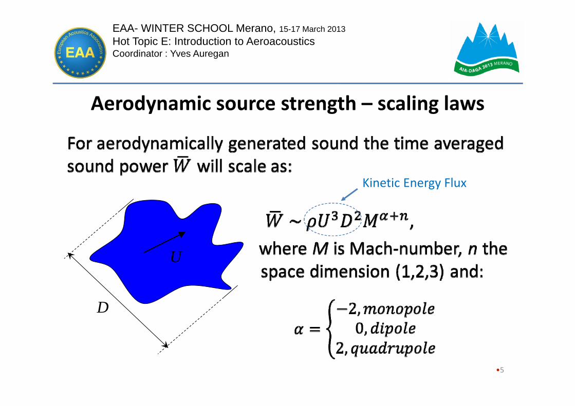
Aerodynamic source strength – scaling laws
•5
U
D
Kinetic Energy Flux

6
Relative strength fluid driven aeroacoustic sources
42 ::1:: MMWWW quadrupoledipolemonopole
- Combustion- Piston machines (in/out flow openings)- Cavitation
-Rotating machines- Flow separation - Free jets
[M=Mach-number=U/c0]

Turbocharger Aero‐Acoustics
• The passive acoustic effect– Reflection, transmission and damping of incoming engine pulses
– Presently modelled with simple 1D models
• The Active acoustic effect– Generation of high frequency sound
– The acoustic power increases with the rotational speed
7

Turbo-Compressor noise sources and transmission paths
TC
Stucture borne sounddue to bearings and unbalances
Flow generated sound in the system Airborne
sound in ducts/pipesAerodynamic sound
from the TC
Radiationfrom openings
Radiationfrom TC body
Radiation
Stucture borne sound in duct/pipe walls

Fan Noisediscrete + broadband
MonopoleRotating shock wavesdiscrete
DipoleBlade forcesdiscrete + broadband
QuadrupoleTurbulence noisebroadband
Steady rotating forces(Gutin noise) discrete
Unsteady rotating forcesdiscrete + broadband
Non-uniformstationaryinflow
discrete
Uniformstationaryinflow
discrete
Non-stationaryinflow
broadband
Tip Clearance Noise Vortex Shedding
narrow-band peak
Very small !!
Sound Generating Mechanisms (the Neise chart)
9

Tonal components of Blade Passing Frequency (BPF)
Averaged sound pressure level in the compressor inlet duct after Raitor&Neise AIAA/CEAS 2006
A compressor wheel of a passenger car turbocharger N (rpm)
BPF = B . N/60, where B is the number of main rotor blades
BPF
10
2007-01-2205
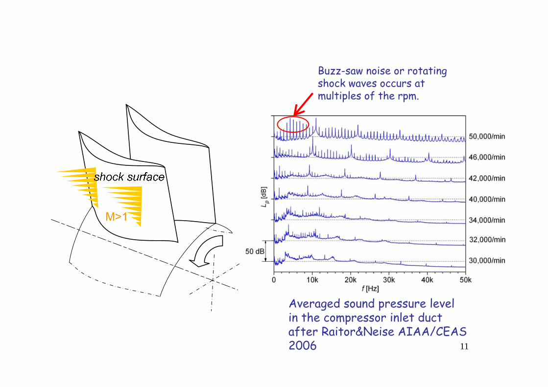
The “buzz-saw noise” starts when the tip speed becomes supersonic Buzz-saw noise or rotating
shock waves occurs at multiples of the rpm.
Averaged sound pressure level in the compressor inlet duct after Raitor&Neise AIAA/CEAS 2006 11

2007-01-2205
Tip clearance noise (TCN) and rotating stall are important at subsonic speeds
Averaged sound pressure level in the compressor inlet duct after Raitor&Neise AIAA/CEAS 2006
RS (broad band peak)
Rotating stall (RS) is normally important at low volume flows and creates a broad band peak at 0.5*rpm. 12

2007-01-2205
Monopole Shock-wave induced “buzz-
saw” noiseDipole2. Tonal noise at blade passing
frequency (BPF)3. Blade tip clearance noise
(TCN)4. Noise from the “rotating
stall” effect5. Secondary (“horse shoe”)
flow
Main noise sources in tur bo-compressors
Here 3-5 represents so called secondary flow effects i.e. related to leakage flows or separation flow at blade tips/edges or along the blade. 13
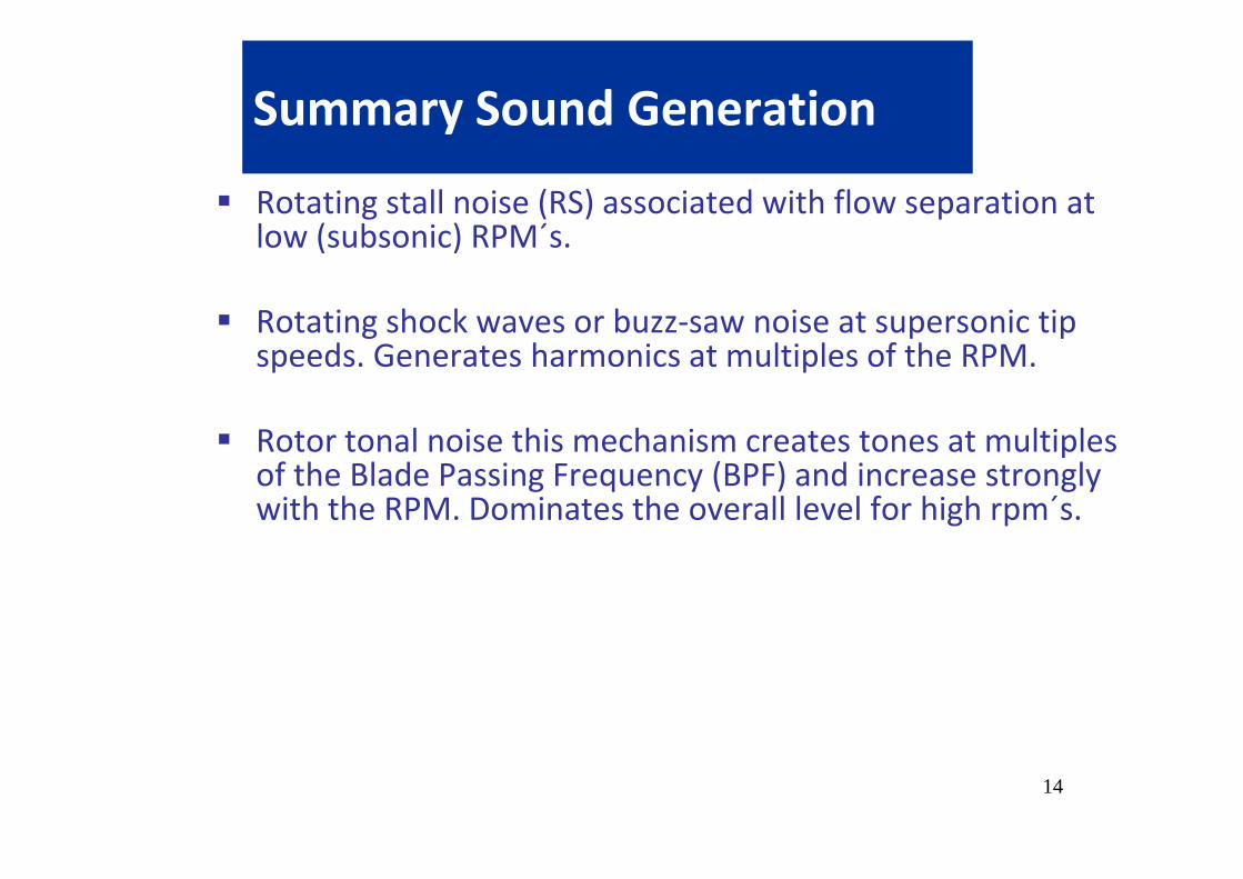
Summary Sound Generation
Rotating stall noise (RS) associated with flow separation at low (subsonic) RPM´s.
Rotating shock waves or buzz‐saw noise at supersonic tipspeeds. Generates harmonics at multiples of the RPM.
Rotor tonal noise this mechanism creates tones at multiplesof the Blade Passing Frequency (BPF) and increase stronglywith the RPM. Dominates the overall level for high rpm´s.
14

Summary Sound Generation
Rotating stall noise (RS) associated with flow separation at low (subsonic) RPM´s.
Rotating shock waves or buzz‐saw noise at supersonic tip speeds. Generates harmonics at multiples of the RPM.
Rotor tonal noise this mechanism creates tones at multiples of the Blade Passing Frequency (BPF) and increase strongly with the RPM. Dominates the overall level for high rpm´s.
The aerodynamic power increases as RPM^3 BUT the aero‐acoustic power increases as ~ RPM^6 ....
15
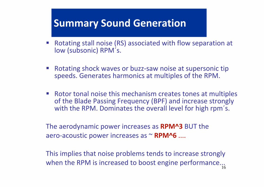
Summary Sound Generation
Rotating stall noise (RS) associated with flow separation at low (subsonic) RPM´s.
Rotating shock waves or buzz‐saw noise at supersonic tip speeds. Generates harmonics at multiples of the RPM.
Rotor tonal noise this mechanism creates tones at multiples of the Blade Passing Frequency (BPF) and increase strongly with the RPM. Dominates the overall level for high rpm´s.
The aerodynamic power increases as RPM^3 BUT the aero‐acoustic power increases as ~ RPM^6 ....
This implies that noise problems tends to increase stronglywhen the RPM is increased to boost engine performance...
16

CCGEx
Competence Center for Gas Exchange (CCGEx) www.ccgex.kth.se
Research focus is on the gas management of IC engines.
The center is a combined effort between KTH, the Swedish Energy Agency and the leading engine manufacturers in Sweden.
Main research fields are fluid mechanics and acoustics.

CCGEx
KTH-CCGEx Acoustic test rig for Turbochargers (TC) TCs are driven by
means of compressed air flow to turbine.
Operation is possible across all the compressor map.
Full acoustic Two-Port data can be determined.

Methods
• Experiments– Flow rig with microphones and loudspeakers up‐ and downstream of the compressor/turbine
• Scattering matrix• Generated sound
• Simulations– Large eddy simulations
• Scattering matrix• Generated sound• Dynamic Mode Decomposition• Correlation of flow and generated sound
19 KTH CCGEx – IAB May 2012

Acoustic measurements forcharacterizing compressor flow instabilities
Raimo Kabral
The work is also supported by the “FlowAirS” initial training network of European Commission FP7 Marie Curie Actions (www.flowairs.eu).

Acoustic 2-port formulation
• The acoustical performance of a flow duct element is determined by the full 2-port model which consists both the passive and the active parts.

The determination of passive part
• Measurement section terminations cannot be absolutely reflection free. This is NO problem for the passive 2-port data (S-matrix).

The determination of passive part• For determination of Scattering
matrix (passive properties) four unknown elements, two independent test scenarios are necessary.
• Two-Source Location method –switching external acoustic excitation location (LS A and LS B).

The determination of passive part• For determination of Scattering
matrix (passive properties) four unknown elements, two independent test scenarios are necessary.
• Two-Source Location method –switching external acoustic excitation location (LS A and LS B).
• In addition, measurement section terminations can be acoustically characterized by means of reflection coefficients.
Needed for active part only to remove rig reflections

Compressor dynamic response
• The scattering matrix also describes the dynamic linear response for the pulsating flow.
• It can be used to compute the damping i.e. transmission loss (TL)
• BUT it can also be used for investigating details of sound-flow interaction, e.g., as appearing at surge
Pre
ssur
e R
atio
Air mass flow
m

• The low frequency plateau region with a level determined by losses and increasing with mass flow extends up to He < 0.2; • This is followed by an upward slope which increases with larger inner volume in the range 0.2 < He < 0.35; • In the range He > 0.35 TL peaks starts to appear associated with resonances due to open/closed bypass gates and with cancellation associated with different sound paths through the blade sections
0.1 0.2 0.3 0.4 0.5 0.6 0.70
5
10
15
20
25
30
35
40
45
Helmholz number (ka)
Tran
smis
sion
loss
(dB
)
0.1 0.2 0.3 0.4 0.5 0.6 0.70
5
10
15
20
25
30
35
40
45
Helmholz number (ka)
Tran
smis
sion
loss
(dB
)
Low ka(losses)
Mid ka(volume)
High ka(resonances)
2 /- duct radius
k f ca
Transmission loss – general behaviourCCGEx

Aero-acoustic coupling
• All flow-acoustic interaction effects (damping & amplification) are included in the determined S-matrix.
• The acoustic power W balance over the element will give the time averaged acoustic power output for a given incident acoustic field:
• The max/min of this expression can be obtained via an eigenvalue analysis* based on S, i.e., to determine max/min
Power Amplification 1out in
in
W WW
*) Y Aurégan, R Starobinski (1999), Acta Acustica United with Acustica 85 (6), 788-792

Results: Aero-acoustic coupling The general trend shows the
high dissipation (neg. amplification) of acoustic power across the frequency range.
There is a sharp reduction of the dissipation at ~.5 of a shaft rotational frequencywhile approaching surge.
Although the reduction grows with shaft rotational frequency, the level remains the same.
80 995 RPM = 1350Hz
690Hz / 1350Hz = 0.51

The determination of active part

Source compactness
•
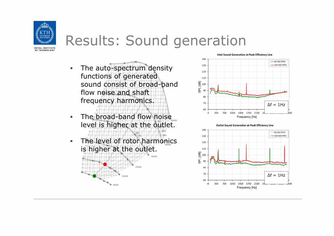
Results: Sound generation
The auto-spectrum density functions of generated sound consist of broad-band flow noise and shaft frequency harmonics.
The broad-band flow noise level is higher at the outlet.
The level of rotor harmonics is higher at the outlet.
∆f = 1Hz
∆f = 1Hz

Results: Source Compactness
The source coherence shows peaks at shaft harmonics (compact source) but otherwise low values i.e. a distribution of uncorrelated sources.

Results: Sound generation A large increase (~25dB) of
broad-band SPL at both sides of the compressor while approaching surge.
Additional contribution to the generated sound spectra more pronounced at the outlet.
∆f = 1Hz
∆f = 1Hz
additional generation
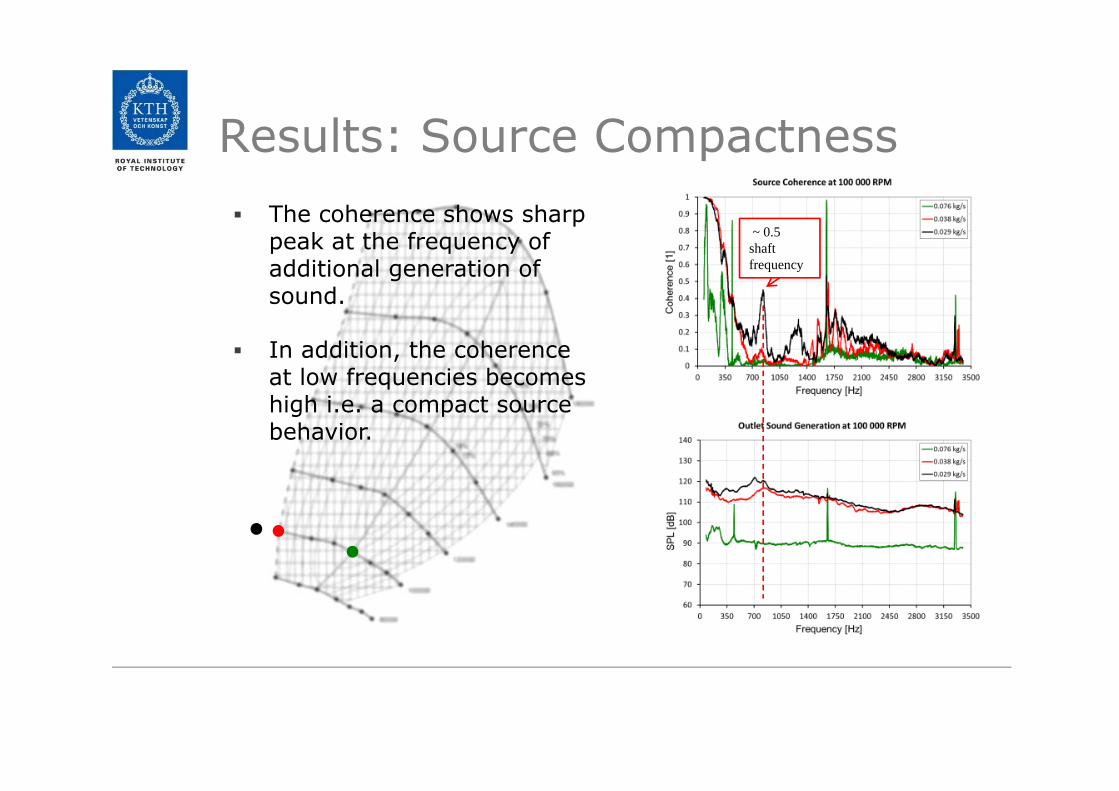
Results: Source Compactness The coherence shows sharp
peak at the frequency of additional generation of sound.
In addition, the coherence at low frequencies becomes high i.e. a compact source behavior.
~ 0.5 shaft frequency

CCGEx
Large Eddy Simulations (LES) of Flow in Turbochargers
Mihai Mihaescu PhD, DocentRoyal Institute of Technology (KTH)Department of MechanicsCompetence Center for Gas Exchange (CCGex) & Linné FLOW CentreStockholm, SwedenE-mail: [email protected]
Contributors:Elias Sundström and Bernhard Semlitsch
CCGEx
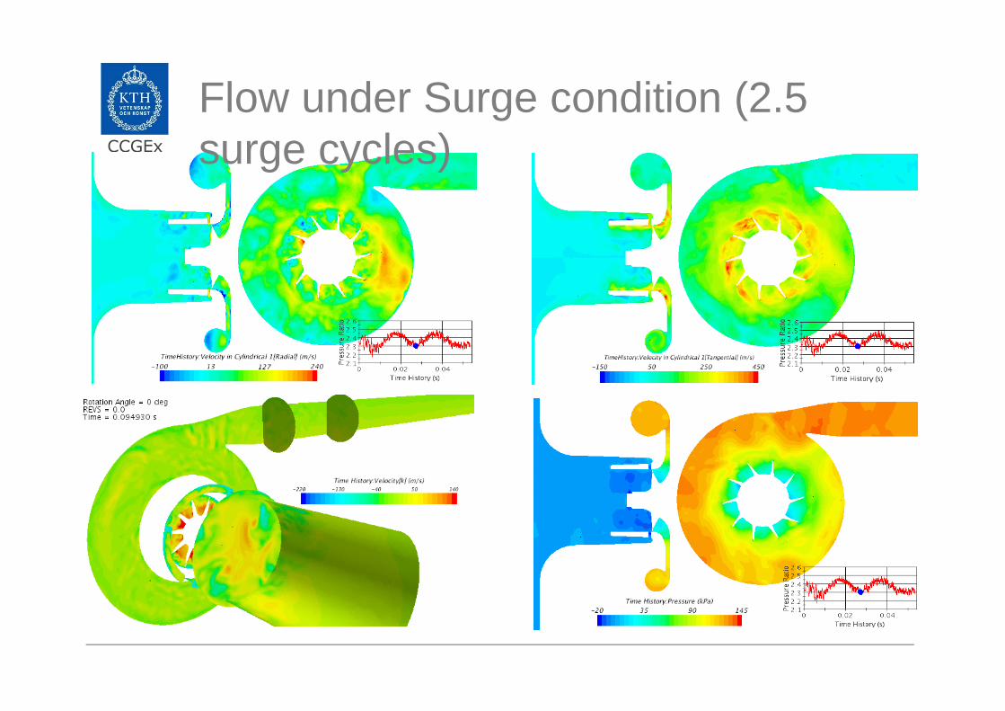
Flow under Surge condition (2.5 surge cycles)

CCGEx
Tangential Radial
3th
PO
D m
ode
POD analysis: Surge conditionM8 (0.05 kg/s)
9th
PO
D m
ode
Tangential Radial
A COMPACT SILENCER FOR THE CONTROL OF COMPRESSOR NOISE
Raimo Kabral, L. Du, M. Åbom, CCGEx KTH Royal Institute of TechnologyM. Knutsson, Volvo Car Corporation
CCGEx
The work is supported by the “FlowAirS” initial training network of European Commission FP7 Marie Curie Actions (www.flowairs.eu).
SAE INTERNATIONAL
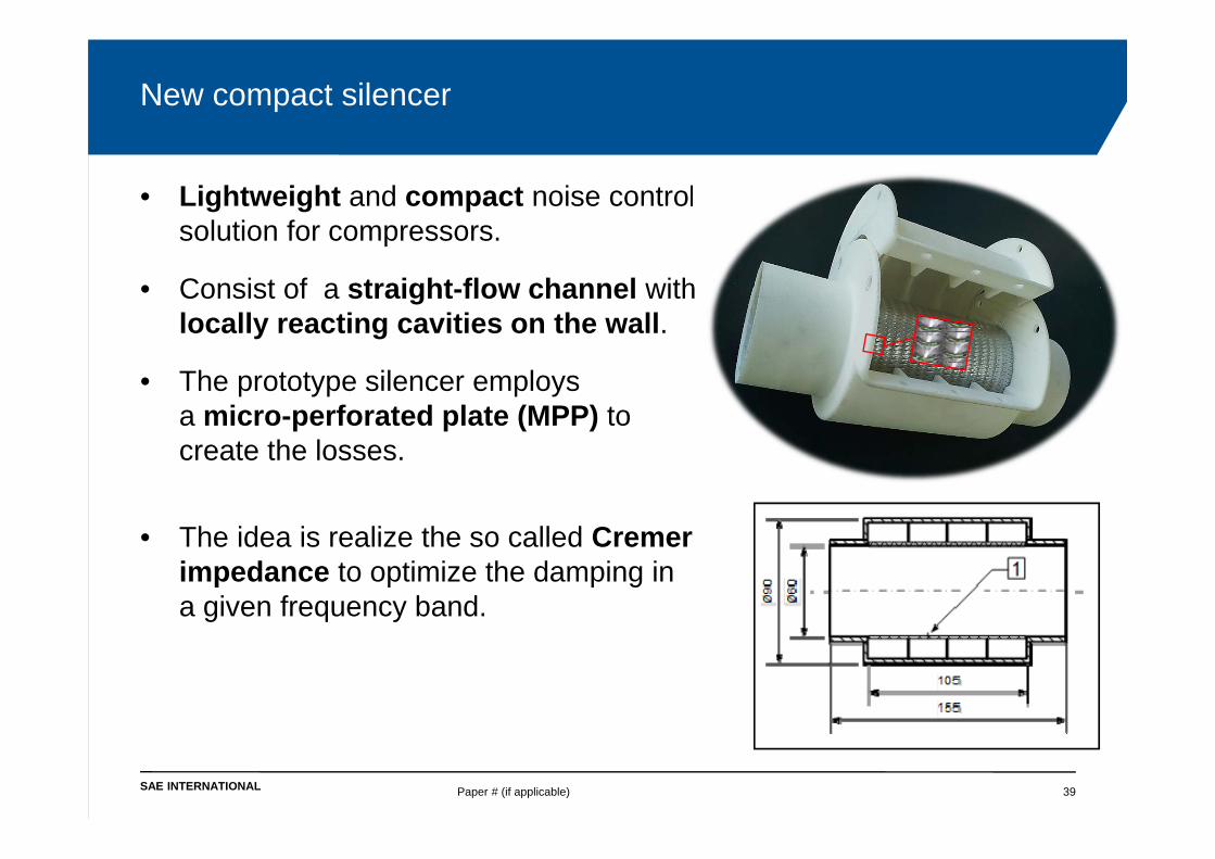
New compact silencer
Paper # (if applicable) 39
• Lightweight and compact noise control solution for compressors.
• Consist of a straight-flow channel with locally reacting cavities on the wall.
• The prototype silencer employs a micro-perforated plate (MPP) to create the losses.
• The idea is realize the so called Cremer impedance to optimize the damping in a given frequency band.

KTH‐CCGEx publications related to the presentationH. Rämmal and M. Åbom, 2007. Acoustics of Turbochargers. SAE paper 2007‐01‐2205. SAE NVH 2007 Conference.
M. Knutsson and M. Åbom, 2009. Sound propagation in narrow tubes including the effects of viscothermal and turbulent damping with application to charge air coolers. Journal of Sound and Vibration 320, pp. 289‐321.
Holmberg, A., Åbom, M. and Bodén, H. (2011). Accurate experimental two‐port analysis of flow generated sound. Journal of Sound and Vibration, DOI: 10.1016/j.jsv.2011.07.04.
Knutsson, M., Lennblad, J., Bodén, H. and Åbom, M. (2011). A Study on Acoustical Time‐Domain Two‐Ports Based on Digital Filters with Application to Automotive Air Intake Systems. SAE Int. J. of Passeng. Cars – Mech. Syst. August 2011 4:970‐982.
Karlsson, M. and Åbom, M. (2011) On the Use of Linear Acoustic Multiports to Predict Whistling in Confined Flows. Acta Acustica vol. 97.
Tiikoja, H., Rämmal, H., Åbom, M. and Boden, H. (2011). Investigations of Automotive Turbocharger Acoustics. SAE Int. J. Engines August 2011 4:2531‐2542.
Kierkegaard, A., Allam, S., Efraimsson, G and Åbom, M. (2012). Simulations of whistling and the whistling potentiality of an in‐duct orifice with linear aeroacoustics. Journal of Sound and Vibration331, 1084–1096.
Kabral, R., Rämmal, H. and Åbom, M. (2013) Acoustical Methods for Investigating Turbocharger Surge. SAE Technical paper 13NVC‐0075.
Jyothishkumar, V., Mihaescu, M., Semlitsch, B., and Fuchs, L., (2013) Numerical Flow Analysis in a Centrifugal Compressor near Surge Condition. AIAA Paper, AIAA 2013‐2730.