turbo-discharging: predicted improvements in engine … · discharging: predicted improvements in...
TRANSCRIPT
Loughborough UniversityInstitutional Repository
Turbo-discharging: predictedimprovements in engine fueleconomy and performance
This item was submitted to Loughborough University's Institutional Repositoryby the/an author.
Citation: WILLIAMS, A.W., BAKER, A.T. and GARNER, C.P., 2011. Turbo-discharging: predicted improvements in engine fuel economy and performance.IN: Proceedings of SAE 2011 World Congress & Exhibition, Detroit, USA, 12th-14th April.
Additional Information:
• This conference paper [2011 c© SAE International] was posted on this sitewith permission from SAE International. Further use and distribution ofthis paper requires permission from SAE International.
Metadata Record: https://dspace.lboro.ac.uk/2134/8710
Version: Published
Publisher: c© SAE International
Please cite the published version.

This item was submitted to Loughborough’s Institutional Repository (https://dspace.lboro.ac.uk/) by the author and is made available under the
following Creative Commons Licence conditions.
For the full text of this licence, please go to: http://creativecommons.org/licenses/by-nc-nd/2.5/

ABSTRACTThe importance of new technologies to improve theperformance and fuel economy of internal combustionengines is now widely recognized and is essential to achieveCO2 emissions targets and energy security. Increasedhybridisation, combustion improvements, friction reductionand ancillary developments are all playing an important partin achieving these goals. Turbocharging technology isestablished in the diesel engine field and will become moreprominent as gasoline engine downsizing is more widelyintroduced to achieve significant fuel economyimprovements.
The work presented here introduces, for the first time, a newtechnology that applies conventional turbomachineryhardware to depressurize the exhaust system of almost anyinternal combustion engine by novel routing of the exhaustgases. The exhaust stroke of the piston is exposed to this lowpressure leading to reduced or even reversed pumping losses,offering >5% increased engine torque and up to 5% reducedfuel consumption. This method has the distinct advantage ofproviding performance and fuel economy improvementswithout significant changes to the structure of the engine, thecombustion system or lubrication system.
The Turbo-Discharging concept is introduced and analyzed.A combination of filling/emptying models and 1-D gasdynamic simulations were used to quantify the energy flowsand identify optimum valve timings and turbomachinecharacteristics. 1-D gas dynamic simulation was then used topredict primary fuel economy benefits from Turbo-Discharging. Secondary benefits, such as extended knocklimits are then discussed.
INTRODUCTIONEngine fuel consumption has been the focus of significantresearch effort for a number of years and is encouraging theintroduction of, for example, downsized enginese.g[1],throttleless air systems[2], new combustion systems as well asnew prime movers. The need to reduce fuel consumption isdriven by concerns over environmental sustainability andenergy security. Despite developments in fuel cell andelectric vehicle technologies, it is now widely recognized thata large fraction of future vehicles will rely on internalcombustion (IC) engines and, therefore, it is important tomake maximum use of the fuel energy to minimize IC enginefuel consumption. In particular, new technologies that do notrequire significant redesign, development and calibration ofestablished engine sub-systems while delivering significantfuel economy benefits are highly valuable.
To improve the thermal efficiency of IC engines, engineerscan address the most significant parasitic losses of the fuelenergy. The most commonly quoted are the energy rejectedthrough the coolant and exhaust systems, which has spurredlarge efforts to recover this thermal energy. Thermo-electricheat recovery systems typically convert <5% of the thermalenergy flowing through them and require rejection of the heatat lower temperatures fundamentally requiring larger heatexchangers[3]. Closed cycles (e.g. Rankine cycle[4]) areapplied to exhaust systems in a research context achieving upto 20% improvements in fuel economy, although theytypically require bulky and heavy hardware. Indeed,packaging and heat rejection requirements are significantlyincreased with exhaust heat recovery methods as most of theenergy must be lost through heat exchangers rather thanexhausted with the combusted gases. This makes them lessattractive for engine manufacturers. Reduction of parasiticpower losses can offer significant improvements. For
Turbo-Discharging: Predicted Improvements inEngine Fuel Economy and Performance
2011-01-0371Published
04/12/2011
Andrew M Williams, Alan T Baker and Colin P GarnerLoughborough Univ.
Copyright © 2011 SAE International
doi:10.4271/2011-01-0371
Loughborough UniversityLicensed from : SAE Digital Library - Copyright 2011 SAE International
E-mailing, copying and internet posting are prohibitedDownloaded Tuesday, August 16, 2011 07:18:11 AM

example, electrical actuation[5] offers the engineer the abilityto use ancillaries only when they are needed and in manycases reduce the fuel consumption across much of the enginerange. Friction also receives a lot of attention and greatimprovements are being made by, for example, surfacetreatments and material developments[6].
Considering the combustion cycle, significant losses arecaused during engine breathing, particularly in throttledengines where the reduction in pumping work has resulted insome of the most significant fuel economy improvements todate, i.e. engine downsizing. However, there is still asignificant amount of energy remaining in the gas at the endof the expansion stroke as the cylinder volume at this time isoften geometrically limited to that of the compression stroke.If the gas could be expanded to that of the exhaust sinkpressure, fuel economy can be dramatically improved. Theturbine in conventional turbocharger arrangements doesrecover some of this energy and uses it to compress the intakeair system, however, much of the energy is lost, especially athigher speeds with a wastegate enabled turbocharger.
Möller et al[7] have implemented turbocharging using onlythe energy contained within the blowdown event which hasthe advantage of reducing the pumping work as the piston no-longer pushes the exhaust gases through the turbine. Thismethod utilized a divided exhaust period first described in[8].This demonstrated significant torque improvements at midand high engine speeds due to pumping work and reductionsin low speed torque due to reduced turbine mass flow. Suchan approach to isolating the blowdown energy from the mainexhaust flow offers an energy source that could be used inmore ways than simply turbocharging.
This paper presents for the first time the Turbo-Dischargingsystem which recovers the blowdown energy and uniquelyapplies this energy to depressurize the exhaust system. Byexposing the piston to this low pressure during the exhauststroke, the pumping work can be reduced or even reversedresulting in positive power out of the engine during the gasexchange. Secondary benefits such as reduced residualcontent may extend existing knock limits to give furtheradvantages.
TURBO-DISCHARGINGTo recover the blowdown energy without demanding thepiston to push the exhaust gases through the turbine thereneeds to be multiple parallel exhaust flow paths. This isachieved by connecting one exhaust valve to a high pressuremanifold (i.e. connected to the turbine inlet) and the secondto a low pressure manifold (i.e. by-passing the turbine),shown in Figure 1. This allows the blowdown energy to berecovered by the turbine while the piston speed is small,resulting in very small work done by the crankshaft
exhausting the gas. During the exhaust stroke of the piston,the low pressure valve is open and the low pressure withinthe cylinder acts to reduce the pumping losses whencompared to pushing the air through the turbine. It is clearthat a rapid valve opening is desirable and in many cases willbe limited by the valve gear. Careful consideration was alsogiven to the overlap of the valves between the high and lowpressure manifolds as this could generate recirculating flows,dissipating useful energy.
The energy can be used in a number of ways including turbo-compounding and turbocharging[5]. In the case of Turbo-Discharging the energy is used to depressurize the exhaustgases by way of a compressor downstream in the exhaustsystem. Such an arrangement is shown for a naturallyaspirated (NA) or supercharged engine in Figure 1. Byreducing the pressure downstream of the turbine (i.e.increasing the pressure ratio) there is the added advantagethat more energy can be extracted from the exhaustblowdown flow. Removing heat from the exhaust gas beforethe compressor increases the gas density and increases thepressure ratio across the compressor for the same powerinput. Since it is the pressure that gives an advantage throughthe crankshaft, the option of installing a heat exchanger tomaximize this heat loss should be considered. With potentialtechnologies such as exhaust thermal energy recovery, it islikely that in the future there will be a mechanism forremoving exhaust thermal energy and, therefore, reducedincentive for an additional heat exchanger.
Figure 1. Schematic of an example exhaust arrangementof a Turbo-Discharged naturally aspirated engine
To implement Turbo-Discharging on a turbocharged (TC)engine the blowdown energy can be recovered in the sameway with the turbocharger turbine situated after the twoexhaust manifolds recombine, shown in Figure 2. Thisensures the turbocharger receives the full engine flow to helpmaintain low speed torque and transient response. Since thelow pressure side of the TC turbine can be ≪0.5 bar
Loughborough UniversityLicensed from : SAE Digital Library - Copyright 2011 SAE International
E-mailing, copying and internet posting are prohibitedDownloaded Tuesday, August 16, 2011 07:18:11 AM
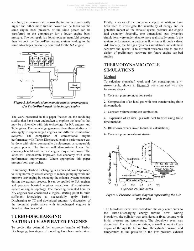
absolute, the pressure ratio across the turbine is significantlyhigher and either more turbine power can be taken for thesame engine back pressure, or the same power can betransferred to the compressor for a lower engine backpressure. The net result is a lower exhaust manifold pressurethan without the Turbo-Discharging system leading to thesame advantages previously described for the NA engine.
Figure 2. Schematic of an example exhaust arrangementof a Turbo-Discharged turbocharged engine
The work presented in this paper focuses on the modelingstudies that have been undertaken to explore the benefits thatmay be achievable with this technology for NA engines andTC engines. The knowledge generated from these studies willalso apply to supercharged engines and different combustionsystems. The comparison of conventional engineperformance with Turbo-Discharged engine performance canbe done with either comparable displacement or comparableengine power. The former will demonstrate lower fueleconomy benefit and increase engine torque and power. Thelatter will demonstrate improved fuel economy with someperformance improvement. Where appropriate this paperpresents both approaches.
In summary, Turbo-Discharging is a new and novel approachto using normally wasted energy to reduce pumping work andimprove scavenging by reducing the exhaust system pressureduring the exhaust process. It can be applied to NA enginesand pressure boosted engines regardless of combustionsystem or engine topology. The modeling presented here forNA engines was considered a logical starting point to buildsufficient knowledge to successfully apply Turbo-Discharging to TC and downsized engines. A discussion ofthe potential performance with turbocharged engines istherefore also presented.
TURBO-DISCHARGINGNATURALLY ASPIRATED ENGINESTo predict the potential fuel economy benefits of Turbo-Discharging, two stages of modeling have been undertaken.
Firstly, a series of thermodynamic cycle simulations havebeen used to investigate the availability of energy and itspotential impact on the exhaust system pressure and enginefuel economy. Secondly, one dimensional gas dynamicssimulations were undertaken to more realistically quantify thesystem performance, in particular flow losses through valves.Additionally, the 1-D gas dynamics simulations indicate howsensitive the system is to different variables and to aid thedesign of preliminary hardware for future engine test-bedstudies.
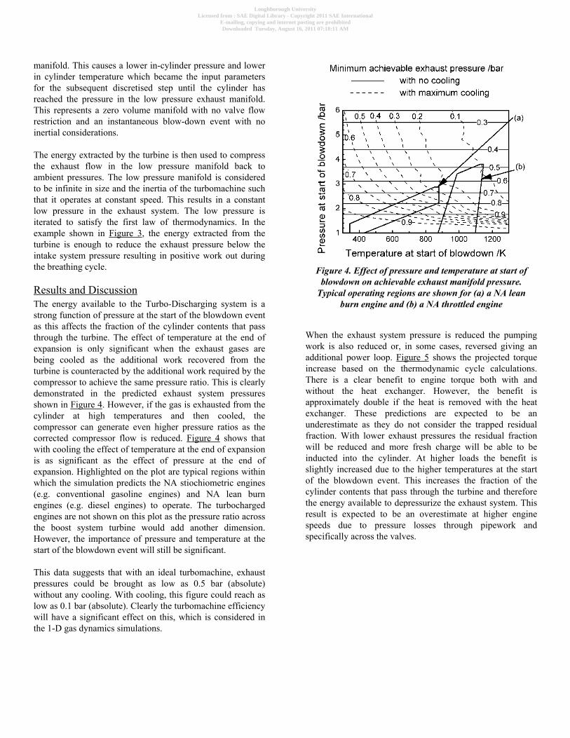
THERMODYNAMIC CYCLESIMULATIONSMethodTo calculate crankshaft work and fuel consumption, a 4-stroke cycle, shown in Figure 3 was simulated with thefollowing stages:
1. Constant pressure induction stroke
2. Compression of an ideal gas with heat transfer using finitetime methods
3. Constant volume complete combustion
4. Expansion of an ideal gas with heat transfer using finitetime methods
5. Blowdown event (linked to turbine calculations)
6. Constant pressure exhaust stroke.
Figure 3. Pressure-volume diagram representing the 0-Dcycle model
The blowdown event was considered the only contributor tothe Turbo-Discharging energy turbine flow. Duringblowdown, the cylinder was considered a fixed volume withinitial pressure and temperature. The blowdown event wasdiscretised. For each discretisation, a small amount of gasexpanded through the turbine from the cylinder pressure andtemperature to the pressure in the low pressure exhaust
Loughborough UniversityLicensed from : SAE Digital Library - Copyright 2011 SAE International
E-mailing, copying and internet posting are prohibitedDownloaded Tuesday, August 16, 2011 07:18:11 AM
manifold. This causes a lower in-cylinder pressure and lowerin cylinder temperature which became the input parametersfor the subsequent discretised step until the cylinder hasreached the pressure in the low pressure exhaust manifold.This represents a zero volume manifold with no valve flowrestriction and an instantaneous blow-down event with noinertial considerations.
The energy extracted by the turbine is then used to compressthe exhaust flow in the low pressure manifold back toambient pressures. The low pressure manifold is consideredto be infinite in size and the inertia of the turbomachine suchthat it operates at constant speed. This results in a constantlow pressure in the exhaust system. The low pressure isiterated to satisfy the first law of thermodynamics. In theexample shown in Figure 3, the energy extracted from theturbine is enough to reduce the exhaust pressure below theintake system pressure resulting in positive work out duringthe breathing cycle.
Results and DiscussionThe energy available to the Turbo-Discharging system is astrong function of pressure at the start of the blowdown eventas this affects the fraction of the cylinder contents that passthrough the turbine. The effect of temperature at the end ofexpansion is only significant when the exhaust gases arebeing cooled as the additional work recovered from theturbine is counteracted by the additional work required by thecompressor to achieve the same pressure ratio. This is clearlydemonstrated in the predicted exhaust system pressuresshown in Figure 4. However, if the gas is exhausted from thecylinder at high temperatures and then cooled, thecompressor can generate even higher pressure ratios as thecorrected compressor flow is reduced. Figure 4 shows thatwith cooling the effect of temperature at the end of expansionis as significant as the effect of pressure at the end ofexpansion. Highlighted on the plot are typical regions withinwhich the simulation predicts the NA stiochiometric engines(e.g. conventional gasoline engines) and NA lean burnengines (e.g. diesel engines) to operate. The turbochargedengines are not shown on this plot as the pressure ratio acrossthe boost system turbine would add another dimension.However, the importance of pressure and temperature at thestart of the blowdown event will still be significant.
This data suggests that with an ideal turbomachine, exhaustpressures could be brought as low as 0.5 bar (absolute)without any cooling. With cooling, this figure could reach aslow as 0.1 bar (absolute). Clearly the turbomachine efficiencywill have a significant effect on this, which is considered inthe 1-D gas dynamics simulations.
Figure 4. Effect of pressure and temperature at start ofblowdown on achievable exhaust manifold pressure.
Typical operating regions are shown for (a) a NA leanburn engine and (b) a NA throttled engine
When the exhaust system pressure is reduced the pumpingwork is also reduced or, in some cases, reversed giving anadditional power loop. Figure 5 shows the projected torqueincrease based on the thermodynamic cycle calculations.There is a clear benefit to engine torque both with andwithout the heat exchanger. However, the benefit isapproximately double if the heat is removed with the heatexchanger. These predictions are expected to be anunderestimate as they do not consider the trapped residualfraction. With lower exhaust pressures the residual fractionwill be reduced and more fresh charge will be able to beinducted into the cylinder. At higher loads the benefit isslightly increased due to the higher temperatures at the startof the blowdown event. This increases the fraction of thecylinder contents that pass through the turbine and thereforethe energy available to depressurize the exhaust system. Thisresult is expected to be an overestimate at higher enginespeeds due to pressure losses through pipework andspecifically across the valves.
Loughborough UniversityLicensed from : SAE Digital Library - Copyright 2011 SAE International
E-mailing, copying and internet posting are prohibitedDownloaded Tuesday, August 16, 2011 07:18:11 AM

Figure 5. Effect of heat exchanger on the potentialtorque increase
Figure 6 shows the projected fuel economy benefit over theengine map for the NA throttled stiochiometric engine ofcomparable displacement. The fuel economy benefit is afunction of the change in pumping mean effective pressure(PMEP) resulting from the use of Turbo-Discharging. As theenergy used to depressurize the exhaust system is increased,the exhaust system pressure asymptotically approaches anabsolute vacuum. At high loads, therefore, the relative benefitreduces. At mid loads the benefit is most significant. At lowerloads, the throttling of the engine can be such that there is nolonger a positive blowdown event (i.e. the pressure at end ofexpansion is lower than atmospheric pressure). Therefore atlow speeds and loads, within the assumptions of thecalculations, there was no energy recovered by the turbineand no benefit of the Turbo-Discharging system. Under theseconditions the valves do not offer significant restriction to theexhaust flow and, therefore, the impact of the Turbo-Discharging system on the pumping work can be negligible.Without cooling, the benefit reduced to ∼3%. Importantly,there is still potential for fuel economy improvements over aconventional engine due to the isolation of the high and lowpressure manifolds. This indicated that a heat exchangercould be sized for optimum mid-low speed mid-low loadoperation and still achieve benefits at higher speeds andloads.
The unthrottled NA stiochiometric engine results, shown inFigure 7 are based on a variable early or late intake valveclosing strategy for load control instead of the throttle. Theresults demonstrate similar trends. However, the threshold atwhich there is no longer a blowdown event is at a higher loaddue to the more efficient operation of the engine.
Figure 6. 0-D model predicted map of fuel economybenefit for a naturally aspirated throttled gasoline engine
(%)
Figure 7. 0-D model predicted fuel economy benefit mapfor a naturally aspirated stoichiometric fuelled throttle-
less engine (%)
The effect of turbomachine efficiency (including compressor,turbine and mechanical efficiency) on the exhaust systempressure is significant. This effect is shown for selectedengine speed and load points in Figure 8. The optimization ofthe turbomachine for efficient operation is, therefore,important. Trade-offs that have been made for inertial reasonson turbochargers should be reconsidered for the case of theTurbo-Discharging system.
Loughborough UniversityLicensed from : SAE Digital Library - Copyright 2011 SAE International
E-mailing, copying and internet posting are prohibitedDownloaded Tuesday, August 16, 2011 07:18:11 AM

Figure 8. Effect of turbomachine efficiency on exhaustsystem pressure at different initial blowdown conditions
ONE-DIMENSIONAL GAS DYNAMICSSIMULATIONSMethodA validated Ford Sigma 1.4 litre naturally aspirated enginemodel (using Ricardo WAVE) was used for this study ofTurbo-Discharging. The exhaust ports were isolated to give ahigh (HP) and a low pressure (LP) manifold which wereconnected to the inlet and outlet of the turbine respectively.This is shown schematically in Figure 1. The specifications ofthis engine are shown in Table 1. The generic turbomachineused for the simulation was comparable in size to a smallautomotive turbocharger.
Table 1. Naturally aspirated simulated enginecharacteristics
To ensure a valid comparison the combustion, heat transfer,exhaust sink pressure and intake valve timings wereconsistent between the models. There is, therefore, scope forfurther improvement with a recalibration of the intake valve
timings. The exhaust valve timings were altered to allowrecovery of the blow-down pulse independently of the maindisplacement pulse. The valve event was scaled within thegeometric constraints of the valve gear and within a 110%limit of the existing valve acceleration. An example of thefinal valve events without the ramp are shown in Figure 9.The amount of overlap between the intake and exhaust valvesis very small to reduce drawing fresh charge through thecylinder into the exhaust manifold. With a port fuel injectionengine this is more important than with direct injectionstrategies where the injection timing can be used to preventunburnt fuel entering the exhaust. At high loads, drawingfresh charge into the exhaust system may have advantages forthermal limits on the turbomachine and scavenging. For allcases presented in this section, fixed valve timings have beenused. Availability of variable valve actuation (VVA) systemson future engines is expected to improve the fuel economyimprovements noticeably.
Figure 9. Example Turbo-Discharging valve events(without ramp) used for 1-D simulations
Results and DiscussionFigure 10 shows the effect of Turbo-Discharging on theengine torque and fuel consumption at wide open throttle.The increase in engine torque was significant and varies fromapproximately 7% to 16% across the speed range. Theassociated increase in peak power was ∼10%. At the sametime, the specific fuel consumption of the engine at peaktorque was reduced. This was anticipated due to the relativereduction in friction work and positive benefit associated withthe reduced exhaust back pressure. However, the fuelconsumption also increased. The effect of the low exhaustpressure on engine breathing, in-cylinder residuals and theamount of fresh charge that was inducted to the cylinder wasas significant as the increased power resulting from reducedpumping work. The torque curve increase over the entireengine speed range is a very positive result. It indicates thatfor typical power densities of NA engines, the breathing
Loughborough UniversityLicensed from : SAE Digital Library - Copyright 2011 SAE International
E-mailing, copying and internet posting are prohibitedDownloaded Tuesday, August 16, 2011 07:18:11 AM

advantages resulting from a low pressure manifold overcomethe detriment resulting from reduced valve lift and openingdurations. Later in this paper the effect of increasing enginepower density is discussed.
Figure 10. Comparison of torque curve betweenconventional and Turbo-Discharged NA engines
As the engine load is reduced, the energy available in theblowdown pulse reduces and the achievable exhaust systempressure also reduces. Figure 11 shows a map of the averageexhaust port pressure as a function of engine speed and load.These are absolute pressures and are therefore typically lowerthan the exhaust sink pressure of 1.05 bar. At peak torque, theexhaust system pressure was seen to reduce to below 0.5 bar.If the piston is exposed to this pressure over its entire exhauststroke, ∼0.5 bar increase in BMEP over the baseline could beexpected. The 2 bar increase (∼ 16%) observed is, therefore,attributed to secondary effects such as reduced residuals andimproved breathing. As anticipated, the lower regions of theengine load do not show a significant reduction in exhaustsystem pressure. This is due to the reverse blowdown, whereat exhaust valve opening, exhaust gases are drawn into thecylinder and cannot be recovered by the turbine arrangementdescribed.
When comparing the translation of exhaust system pressureto fuel economy benefit, two cases were considered:comparable displacement and comparable engine power.Figure 12 shows a map of the predicted fuel economyimprovement as a function of engine speed and load for thecomparable displacement engines. There was a translation ofthe exhaust system pressure to reduced pumping work atmost engine conditions, specifically in the lower half of theengine speed range. At higher speeds, the benefit wasreduced, resulting from the flow restrictions through thevalves. Only at very high speeds and loads were significantfuel economy detriments (>1%) observed.
Figure 11. Exhaust port absolute pressure (in bar) as afunction of engine speed and load
Figure 12. Fuel economy benefit for a comparabledisplacement engine
Considering the exhaust system pressure, it was possible toestimate the ideal fuel economy improvement based on thepotential effect of exhaust pressure on PMEP and thereduction in residual content on throttling requirements. Thisconsidered the case when the low exhaust system pressure isapplied to the cylinder throughout the entire exhaust stroke,and therefore gave a quantitative term that could be comparedto the actual fuel economy benefit to evaluate how effectivelythe exhaust system pressure is translated into fuel economyimprovement. It is calculated as
Eq. (1)
Loughborough UniversityLicensed from : SAE Digital Library - Copyright 2011 SAE International
E-mailing, copying and internet posting are prohibitedDownloaded Tuesday, August 16, 2011 07:18:11 AM

where Iexpected is the expected improvement to BSFC (%), Pis pressure and r is residual fraction. Subscript ex refers toexhaust port, in refers to intake port, T to the Turbo-Discharged engine, N to the baseline engine and BMEP to thebrake mean effective pressure. Equation 1 does take intoaccount the additional throttling required to achieve the sameload as the residual content and PMEP reduces. Theeffectiveness of the chosen valve profiles and timings totranslate the exhaust system pressure into fuel economyimprovement was therefore be defined as
Eq. (2)
where Iactual is the actual fuel economy benefit and Ebreathingis the breathing effectiveness. It is worth highlighting that theeffectiveness can potentially increase beyond 100 if themanifolds are successfully tuned. Figure 13 shows thecalculated breathing effectiveness across most of the enginemap. It can be seen that the valve profiles were successful atlower speeds and struggled to achieve a lower pressuredifferential across the valves at higher engine speeds. There isscope, therefore to reduce the amount of work being used todepressurize the exhaust at higher engine speeds to allow theincrease of valve lift and duration.
Figure 13. Map of breathing effectiveness, Ebreathing (%,defined in Eq 2)
When considering an engine of comparable power, thecomparison became that shown in Figure 14. The torquecurves are shown for comparison and are not significantlydifferent. The highest fuel economy improvements are againaround the low-mid speed and mid load portions of theengine map, reaching >5% and, importantly, fuel economyimprovements were recognized at all engine speeds andloads. Of particular importance are the fuel economy benefitsachieved at very low loads due to reduced friction andpumping work. In practice, the engine designers would beable to work in a continuous spectrum between the casespresented in Figures 12 and 14, balancing the value ofimproved fuel economy with improved engine torque andpower.
Figure 14. Fuel economy improvement (%) for acomparable power engine
The change of residual fraction is of interest as it is the mostsignificant effect of Turbo-Discharging on combustion. Withreduced residual content the knock limit is expected to befurther extended allowing potentially increased power densityand potentially higher compression ratios than used in thesesimulations. Figure 15 shows that the residual content wassignificantly reduced across most of the engine range. At highloads, 50% reduction of in cylinder residuals was predicted.At low speeds, increase residuals were identified due to thechange in engine breathing. Provided stable combustion canbe maintained, this has the effect of reducing the throttlingrequired and further increasing engine efficiency. At midspeed and load, the effect would be reverse and reducedresiduals will require more throttling and increased pumpingwork. At high speeds, the residual content increases slightly,however, it is anticipated that with VVA strategies, theresidual content across the entire map could be improved.
Loughborough UniversityLicensed from : SAE Digital Library - Copyright 2011 SAE International
E-mailing, copying and internet posting are prohibitedDownloaded Tuesday, August 16, 2011 07:18:11 AM

Figure 15. Effect of Turbo-Discharging on trappedresidual fraction (% increase)
Sensitivity AnalysisThe results so far presented a single valve timing appliedacross the entire engine operating range. The followingdiscussion investigates how sensitive the system behavior isto LP exhaust valve timing, HP exhaust valve timing, theamount of heat removed (via heat exchanger size) and theturbomachine efficiency. To represent different regions of themap the following cases are presented:
1. 2000 rpm, full load
2. 5000 rpm, full load
3. 2000 rpm, 4 bar BMEP
4. 4000 rpm, 6 bar BMEP
2000 rpm, full loadFigure 16a shows the sensitivity of the exhaust port pressureto the variables previously described. Notably, the system isremarkably insensitive to these variables. The mostsignificant variable is the turbomachine efficiency which, byvarying between 30 and 42%, results in a 0.2 bar variation inexhaust system pressure. The low pressure valve timing hasalmost no effect. The high pressure valve timing is slightlymore sensitive since with high cylinder pressures, early valveopening results in higher pressures and temperatures at thestart of blowdown and therefore more energy available toreduce the exhaust system pressure. Heat exchanger size hasnegligible effect indicating that the heat exchanger isoversized for this operating condition.
The torque increase resulting from Turbo-Discharging,shown in Figure 16b, is sensitive to turbomachine efficiency.The effect of high pressure valve opening is very smalldespite the effect on exhaust system pressure as earlier valveopening also reduces the expansion work from the engine.
Later low pressure exhaust valve timings increase valveoverlap with the intake system and therefore allow improvedscavenging and increased torque.
Figure 16. Sensitivity of (a) exhaust port pressure and(b) torque increase, to valve timing, heat rejection and
turbomachine efficiency at 2000 rpm full load
5000 rpm full loadAt higher engine speeds (5000 rpm) the comparablesensitivity plots are shown in Figure 17. The importance ofturbomachine efficiency is still apparent. The effects of valvetiming were comparable to that in Figure 16. The effect of theheat exchanger is small, but more significant than at lowerspeeds. As with the previous case, the system is remarkablyinsensitive to the range of variables studied. The trade-offbetween heat exchanger size and benefit is most significant athigh powers. If the importance is placed at lower enginepower conditions, the heat exchanger size can be significantlyreduced.
Loughborough UniversityLicensed from : SAE Digital Library - Copyright 2011 SAE International
E-mailing, copying and internet posting are prohibitedDownloaded Tuesday, August 16, 2011 07:18:11 AM

Figure 17. Sensitivity of (a) exhaust port pressure and(b) torque increase, to valve timing, heat rejection and
turbomachine efficiency at 5000 rpm full load
Part load
Figure 18. Sensitivity of exhaust port pressure to valvetiming, heat rejection and turbomachine efficiency at (a)
2000 rpm 4 bar BMEP and (b) 4000 rpm 6 bar BMEP
Figure 18 (cont.). Sensitivity of exhaust port pressure tovalve timing, heat rejection and turbomachine efficiency
at (a) 2000 rpm 4 bar BMEP and (b) 4000 rpm 6 barBMEP
Figures 18a and 18b show the exhaust system pressure at2000 rpm 4 bar BMEP and 4000 rpm 6 bar BMEPrespectively. The trends support the discussion for the fullload cases where the importance of heat exchanger size onlystarts to become apparent at higher engine powers.
Summary of Sensitivity StudyIn summary, Turbo-Discharging is not sensitive to exhaustvalve timing (+/− 10 deg crank angle) or heat exchanger size(between 3 and 12 litres). This indicates that manufacturingvariations and tolerances do not need to be tightened toachieve a positive result. The turbomachine efficiency has themost significant effect. To achieve fast transient responsewith conventional turbochargers there are many designfeatures, such as scalloping of the turbine blades and smallturbine size that have resulted in ∼20% reduction inturbomachine efficiency[9]. It is important to understand theeffect of the transient response of this system on driverperceptions as the peak engine power is less dependent onTurbo-Discharging than it would be with a conventionalturbocharger system. This may allow significantly moreefficient turbomachines to be used. A thorough study oftransient response is beyond the scope of the work presentedhere.
The packaging in automotive engine bays is a significantchallenge and the heat exchanger size should be minimized.Varying heat exchanger size between 3 and 12 litres wasshown to not significantly affect the engine performance. Theeffect of heat exchanger size was investigated further. Theexhaust system pressure at 5000 rpm, full load is shown inFigure 19 for heat exchanger sizes approaching 0 litres.Significant reduction in exhaust system pressure was seen atvery small heat exchanger sizes. In addition, if priority isassigned to lower engine power operating conditions, the
Loughborough UniversityLicensed from : SAE Digital Library - Copyright 2011 SAE International
E-mailing, copying and internet posting are prohibitedDownloaded Tuesday, August 16, 2011 07:18:11 AM

thermal demand on the heat exchanger will be significantlyreduced.
Figure 19. Effect of heat exchanger size on exhaust portpressure at 5000 rpm, full load
TURBO-DISCHARGINGTURBOCHARGED ENGINESFuture fuel economy and CO2 emission targets are likely torequire downsizing of engines. This would be achieved byturbocharging which introduces a further level of complexityto the Turbo-Discharging system. Initial studies are focusedon naturally aspirated engines to understand the fundamentalsof the Turbo-Discharging system, however, it was importantto explore the impact of increasing engine power density,particularly on engine breathing capability. A schematic ofthe exhaust arrangement for the Turbo-Dischargedturbocharged engine has already been shown in Figure 2.Since the post TC turbine pressure is lower, the pressure ratioacross the TC turbine is higher and more work can be donefor the same upstream exhaust system pressure. The net resultis, to achieve the same engine boost levels, a lower backpressure will be applied to the engine. The gas will havefurther expanded and be at a lower temperature on turbineentry offering additional benefits for VGT turbochargerdurability. Calculation of the exhaust port pressures needed toachieve a specific turbine energy recovery are shown inFigure 20 for the conventional engine and a Turbo-Discharged engine to compare the effect of Turbo-Discharging (with a pressure ratio of 2 across thecompressor) on exhaust system back pressure (as seen by theengine). Higher specific turbine energies correspond to higherboost levels and, therefore, engine load. The reduction inback pressure increases with specific turbine energy recoveryat a slower rate than engine power output would. Therefore,at higher boost conditions, the fuel economy benefit will besmaller than at lower boost conditions.
Figure 20. Effect of Turbo-Discharging on exhaust portback pressure as a function of turbocharger turbine
energy demand
Figures 21 and 22 show the predicted fuel economy benefitfrom the 0-D simulations described previously, applied toturbocharged diesel and gasoline engine architecturesrespectively. The benefit is a maximum at mid loads,reducing at light loads due to the reduced blowdownintensity. At higher loads, the engine torque increases morethan the possible improvements to BMEP meaning that theoverall fuel economy benefit reduces. Although the highestbenefit was predicted at high engine speeds, breathinglimitations will limit the fuel economy benefit at theseconditions. For the case of the gasoline engine, assuming aVGT is used to minimize the engine back pressure and fuelconsumption, the maximum benefit is observed atapproximately the same BMEP as the naturally aspiratedengines. As the BMEP increases further, the improvements toPMEP are smaller in comparison to the increases in BMEPand as such, the relative benefit reduces. Due to modelingassumptions, benefits at higher power conditions are expectedto be an overestimate due to flow restrictions across valves.
To understand the potential of Turbo-Discharging on higherpower density engines, the 1-D naturally aspirated enginemodel was modified to represent a pressure charged engine(e.g. supercharged) to investigate the breathing limits on thevalve timings chosen. Combustion and in-cylinder pressurelimits were not considered so that the focus was on thebreathing limits related to the valves and manifolds. Theresults are shown in Figure 23. As the power densityincreased the peak engine torque at 5000 rpm approached thatof the same engine model without Turbo-Discharging (i.e.conventional valve timings and exhaust system). Atapproximately 130 kW litre−1 the power output at 5000 rpmwas the same between both engines. At 170 kW litre−1 thepower output of the Turbo-Discharged engine had reduced to∼0.5% less than the equivalent engine with conventionalvalving and exhaust systems. Despite this reduction in torque
Loughborough UniversityLicensed from : SAE Digital Library - Copyright 2011 SAE International
E-mailing, copying and internet posting are prohibitedDownloaded Tuesday, August 16, 2011 07:18:11 AM

at high speeds, the majority of the torque curve below 5000rpm was higher with the Turbo-Discharging system.
Figure 21. Predicted Fuel economy improvements (%)for a turbocharged diesel engine
Figure 22. Predicted fuel economy improvements (%) fora turbocharged gasoline engine
Figure 23. Effect of intake pressure boosting onbreathing limited torque benefit of Turbo-Discharging at
5000 rpm, full load
Figure 24 shows the fresh air flow into the engine as afunction of speed at ∼170 kW litre−1 engine power density.Across the entire engine speed range the engine airflow isincreased. This would normally be reflected in an increase ofengine peak power, however, the reduced exhaust valveevents under such high power densities result in higher backpressures during the exhaust stroke. Figure 25 shows the in-cylinder pressure during the exhaust stroke. Through most ofthe stroke the in-cylinder pressures are significantly higherand contribute up to 1 bar to the PMEP. However, towardsthe end of the exhaust event, the in-cylinder pressures aresignificantly lower. With no valve overlap this in itself wouldsignificantly reduce hot residuals. With valve overlap, thelower exhaust pressures promote flow from the intakethrough to the exhaust, further reducing in-cylinder trappedresiduals.
Figure 24. Engine full load fresh air flow as a functionof engine speed at ∼170 kW litre−1 engine power density,
full load
Loughborough UniversityLicensed from : SAE Digital Library - Copyright 2011 SAE International
E-mailing, copying and internet posting are prohibitedDownloaded Tuesday, August 16, 2011 07:18:11 AM
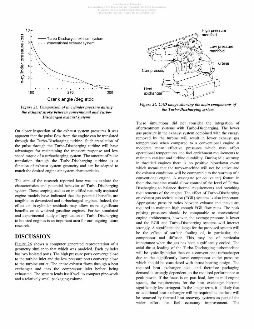
Figure 25. Comparison of in cylinder pressure duringthe exhaust stroke between conventional and Turbo-
Discharged exhaust systems
On closer inspection of the exhaust system pressures it wasapparent that the pulse flow from the engine can be translatedthrough the Turbo-Discharging turbine. Such translation ofthe pulse through the Turbo-Discharging turbine will haveadvantages for maintaining the transient response and lowspeed torque of a turbocharging system. The amount of pulsetranslation through the Turbo-Discharging turbine is afunction of exhaust system geometry and can be adapted tomatch the desired engine air system characteristics.
The aim of the research reported here was to explore thecharacteristics and potential behavior of Turbo-Dischargingsystem. These scoping studies on modified naturally aspiratedengine models have indicated that the potential benefits aretangible on downsized and turbocharged engines. Indeed, theeffect on in-cylinder residuals may allow more significantbenefits on downsized gasoline engines. Further simulatedand experimental study of application of Turbo-Dischargingto boosted engines is an important area for our ongoing futureresearch.
DISCUSSIONFigure 26 shows a computer generated representation of ageometry similar to that which was modeled. Each cylinderhas two isolated ports. The high pressure ports converge closeto the turbine inlet and the low pressure ports converge closeto the turbine outlet. The entire exhaust flows through a heatexchanger and into the compressor inlet before beingexhausted. The system lends itself well to compact pipe-workand a relatively small packaging volume.
Figure 26. CAD image showing the main components ofthe Turbo-Discharging system
These simulations did not consider the integration ofaftertreatment systems with Turbo-Discharging. The lowergas pressure in the exhaust system combined with the energyremoved by the turbine will result in lower exhaust gastemperatures when compared to a conventional engine atmoderate mean effective pressures which may affectoperational temperatures and fuel enrichment requirements tomaintain catalyst and turbine durability. During idle warmupin throttled engines there is no positive blowdown eventwhich means that the turbo-machine will not be active andthe exhaust conditions will be comparable to the warmup of aconventional engine. A wastegate (or equivalent) feature inthe turbo-machine would allow control of the level of Turbo-Discharging to balance thermal requirements and breathingrequirements of the engine. The effect of Turbo-Dischargingon exhaust gas recirculation (EGR) systems is also important.Appropriate pressure ratios between exhaust and intake arerequired to maintain high enough EGR flow rates. The peakpulsing pressures should be comparable to conventionalengine architectures, however, the average pressure is lowerand the EGR and Turbo-Discharging systems will interactstrongly. A significant challenge for the proposed system willbe the effect of surface fouling of, in particular, thecompressor and diffuser. This may be of particularimportance when the gas has been significantly cooled. Theaxial thrust loading of the Turbo-Discharging turbomachinewill be typically higher than on a conventional turbochargerdue to the significantly lower compressor outlet pressureswhich should be considered with thrust bearing design. Therequired heat exchanger size, and therefore packagingdemand is strongly dependent on the required performance atpeak power. If the focus is on part load, low to mid enginespeeds, the requirements for the heat exchanger becomesignificantly less stringent. In the longer term, it is likely thatno additional heat exchanger will be required as the heat willbe removed by thermal heat recovery systems as part of thewider effort for fuel economy improvement. The
Loughborough UniversityLicensed from : SAE Digital Library - Copyright 2011 SAE International
E-mailing, copying and internet posting are prohibitedDownloaded Tuesday, August 16, 2011 07:18:11 AM

quantification of the interactions described here are the focusof current experimental research efforts and will be reportedin future publications.
CONCLUSIONSThis paper has, for the first time, introduced the novel Turbo-Discharging system which recovers energy from theblowdown pulse of IC engines and uses it to depressurize theengine exhaust system. Turbo-Discharging can be applied toany engine topology where there is a blowdown event. Thepaper has presented the results of modeling studiesinvestigating the characteristics and behavior of the Turbo-Discharging system and explored its application to naturallyaspirated and, to a lesser extent, boosted engine architectures.This will aid future experimental programs and has led to thefollowing conclusions:
1. Turbo-Discharging can reduce or even reverse pumpinglosses from an internal combustion engine by reducing theexhaust manifold pressure. Exhaust pressures of <0.5 barabsolute were predicted for the naturally aspirated engine.This increased engine torque and improved fuel economyover a significant fraction of the engine map.
2. Fuel economy improvements of ∼5% were predictedwhen compared to a naturally aspirated engine of the samepower.
3. At all engine conditions investigated, the naturallyaspirated engine Turbo-Discharging system performance isrelatively insensitive to exhaust valve timing and heatexchanger size. Turbo-machine efficiency has a moreimportant effect.
4. The lower exhaust pressure will translate through aturbocharging system turbine to give lower pumping losseson a turbocharged engine.
5. Trapped residual content is reduced significantly for bothnaturally aspirated engines (>40% reduction) and isanticipated for highly boosted engines due to lower incylinder pressures around EVC and an intake to exhaustpressure ratio that encourages scavenging. This could offersignificant secondary benefits to combustion by extending theknock limit.
6. Preliminary investigations of boosted engine breathingindicated that breathing limited engine torque improvementswill occur below power densities of ∼140 kW litre−1.However, at all power densities included, the trapped (hot)residual fraction was significantly reduced giving scope forincreased boost or compression ratio by extending the knocklimit.
The preliminary modeling results are encouraging. Thetechnological challenges such as packaging, EGR systemintegration and exhaust gas aftertreatment integration areimportant and will form part of future experimental study ofthe performance of a Turbo-Discharging system on-engine.
REFERENCES1. Shahed, S. and Bauer, K., “Parametric Studies of theImpact of Turbocharging on Gasoline Engine Downsizing,”SAE Int. J. Engines 2(1):1347-1358, 2009, doi:10.4271/2009-01-1472.
2. Flierl, R., Paulov, M., Knecht, A., and Hannibal, W.,“Investigations with a Mechanically Fully Variable ValveTrain on a 2.01 Turbo Charged Four Cylinder Engine,” SAETechnical Paper 2008-01-1352, 2008, doi:10.4271/2008-01-1352.
3. Mori, M., Yamagami, T., Oda, N., Hattori, M. et al.,“Current Possibilities of Thermoelectric Technology Relativeto Fuel Economy,” SAE Technical Paper 2009-01-0170,2009, doi:10.4271/2009-01-0170.
4. Ringler, J., Seifert, M., Guyotot, V., and Hübner, W.,“Rankine Cycle for Waste Heat Recovery of IC Engines,”SAE Int. J. Engines 2(1):67-76, 2009, doi:10.4271/2009-01-0174.
5. Lyu, M., Doo, B., and Ku, Y., “A Study of Vehicle FuelEconomy Improvement Potential by Optimization of theCooling and Ancillary Systems of a Heavy Duty Engine,”SAE Technical Paper 2007-01-1772, 2007, doi:10.4271/2007-01-1772.
6. Improving fuel efficiency with laser surface texturedpiston rings. Etsion, I. and Sher, E.. Tribology InternationalVol 42 pp 542-547, 2009.
7. Möller, C., Johansson, P., Grandin, B., and Lindström, F.,“Divided Exhaust Period - A Gas Exchange System forTurbocharged SI Engines,” SAE Technical Paper2005-01-1150, 2005, doi:10.4271/2005-01-1150.
8. Improvements in or relating to internal combustionengines. Society Rateau. British patent no. 12,227/22, 1924
9. Fundamentals of Turbocharging. Baines, N.C.. ConceptsNREC, Vermont, USA, 2005
CONTACT INFORMATIONDr. Andy WilliamsWolfson School of Mechanical and ManufacturingEngineeringLoughborough UniversityLeicestershire LE11 [email protected]: +44 1509 227 651
ACKNOWLEDGEMENTSThe authors would like to acknowledge the support the RoyalAcademy of Engineering and that of the Engineering andPhysical Sciences Research Council (EPSRC) andTechnology Strategy Board (TSB) as part of the Low Carbon
Loughborough UniversityLicensed from : SAE Digital Library - Copyright 2011 SAE International
E-mailing, copying and internet posting are prohibitedDownloaded Tuesday, August 16, 2011 07:18:11 AM

Vehicles Integrated Delivery Programme (Grant EP/H050353/1) for supporting this research.
DEFINITIONS/ABBREVIATIONS0-D
Zero-dimensional
1-DOne-dimensional
BMEPBrake mean effective pressure
CADComputer aided design
CO2Carbon dioxide
EVCExhaust valve closing
HPHigh pressure
ICInternal combustion
LPLow pressure
NANaturally aspirated
PMEPPumping mean effective pressure
TCTurbocharged
VGTVariable geometry turbine
VVAVariable valve actuation
The Engineering Meetings Board has approved this paper for publication. It hassuccessfully completed SAE's peer review process under the supervision of the sessionorganizer. This process requires a minimum of three (3) reviews by industry experts.
All rights reserved. No part of this publication may be reproduced, stored in aretrieval system, or transmitted, in any form or by any means, electronic, mechanical,photocopying, recording, or otherwise, without the prior written permission of SAE.
ISSN 0148-7191
Positions and opinions advanced in this paper are those of the author(s) and notnecessarily those of SAE. The author is solely responsible for the content of the paper.
SAE Customer Service:Tel: 877-606-7323 (inside USA and Canada)Tel: 724-776-4970 (outside USA)Fax: 724-776-0790Email: [email protected] Web Address: http://www.sae.orgPrinted in USA
Loughborough UniversityLicensed from : SAE Digital Library - Copyright 2011 SAE International
E-mailing, copying and internet posting are prohibitedDownloaded Tuesday, August 16, 2011 07:18:11 AM