turbo-slide installation manual
TRANSCRIPT

R Y T E C
P.O. Box 403, One Cedar Parkway, Jackson, WI 53037 Phone: 262-677-9046 Fax: 262-677-2058
Rytec Website: www.rytecdoors.com, Rytec On-line store: www.rytecparts.com Rytec E-mail: [email protected], Parts E-mail: [email protected]
[Revision: March 15th, 2016, R1091003-0, ™ Rytec Corporation 2015]
Turbo Slide™
Installation Manual


TABLE OF CONTENTS
PAGE
INTRODUCTION . . . . . . . . . . . . . . . . . . . . . . . . . . . . . . . . . . . . . . . . . . . 1
DOOR IDENTIFICATION SERIAL NUMBER(S) . . . . . . . . . . . . . . . . . . . . . . 1
HOW TO USE MANUAL . . . . . . . . . . . . . . . . . . . . . . . . . . . . . . . . . . . . . . . . . 1
INSTALLATION . . . . . . . . . . . . . . . . . . . . . . . . . . . . . . . . . . . . . . . . . . . . . 2
MATERIAL, TOOLS, AND EQUIPMENT . . . . . . . . . . . . . . . . . . . . . . . . . . . . 2
ADDITIONAL REQUIREMENTS . . . . . . . . . . . . . . . . . . . . . . . . . . . . . . . . . . 2
Labor and Site Requirements. . . . . . . . . . . . . . . . . . . . . . . . . . . . . 2
Forklift Requirements . . . . . . . . . . . . . . . . . . . . . . . . . . . . . . . . . . . 2
Electrician’s Responsibilities . . . . . . . . . . . . . . . . . . . . . . . . . . . . . 2
Pullout/Bucking Recommendations . . . . . . . . . . . . . . . . . . . . . . . . 2
GENERAL ARRANGEMENT OF DOOR COMPONENTS . . . . . . . . . . . . . . . . . . . . . . 3
ANCHORING METHODS . . . . . . . . . . . . . . . . . . . . . . . . . . . . . . . . . . . . . . . . . . . . . . . 4
Concrete, Block, or Brick Walls . . . . . . . . . . . . . . . . . . . . . . . . . . . . . . . . . . . 4
Wood, Block, Brick, or Insulated Walls . . . . . . . . . . . . . . . . . . . . . . . . . . . . . 4
Insulated Wall . . . . . . . . . . . . . . . . . . . . . . . . . . . . . . . . . . . . . . . . . . . . . . . . . 4
UNCRATING . . . . . . . . . . . . . . . . . . . . . . . . . . . . . . . . . . . . . . . . . . . . . . . . . . . . . . . . . 5
DETERMINE PLUMB/SQUARE OF DOOR OPENING . . . . . . . . . . . . . . . . . . . . . . . . . 5
LOCATING CENTERLINE OF DOOR OPENING (BI-PARTING DOOR) . . . . . . . . . . . 5
BULB SEALS . . . . . . . . . . . . . . . . . . . . . . . . . . . . . . . . . . . . . . . . . . . . . . . . . . . . . . . . 6
Bulb Seal Frame . . . . . . . . . . . . . . . . . . . . . . . . . . . . . . . . . . . . . . . . . . . . . . . . 6
Bulb Seal Installation . . . . . . . . . . . . . . . . . . . . . . . . . . . . . . . . . . . . . . . . . . . . 7
HEAT TAPE . . . . . . . . . . . . . . . . . . . . . . . . . . . . . . . . . . . . . . . . . . . . . . . . . . . . . . . . . . 8
HEAD ASSEMBLY . . . . . . . . . . . . . . . . . . . . . . . . . . . . . . . . . . . . . . . . . . . . . . . . . . . . . 8
PANEL INSTALLATION . . . . . . . . . . . . . . . . . . . . . . . . . . . . . . . . . . . . . . . . . . . . . . . . . 9
STAY ROLLER INSTALLATION . . . . . . . . . . . . . . . . . . . . . . . . . . . . . . . . . . . . . 10
PHOTO EYE INSTALLATION . . . . . . . . . . . . . . . . . . . . . . . . . . . . . . . . . . . . . . . 10
ELECTRICAL SYSTEM . . . . . . . . . . . . . . . . . . . . . . . . . . . . . . . . . . . . . . . . . . . . 10
TESTING PHOTO EYES . . . . . . . . . . . . . . . . . . . . . . . . . . . . . . . . . . . . . . . . . . . . 10
PHOTO EYE TROUBLESHOOTING . . . . . . . . . . . . . . . . . . . . . . . . . . . . . . . . . . . 10
DOOR LIMIT POSITIONS . . . . . . . . . . . . . . . . . . . . . . . .. . . . . . . . . . . . . . . . . . . . 11
BI-PARTING DOOR . . . . . . . . . . . . . . . . . . . . . . . . . . . . . . . . . . . . . . . . . . 11
CLOSE LIMIT . . . . . . . . . . . . . . . . . . . . . . . . . . . . . . . . . . . . . . . . 11
OPEN LIMIT . . . . . . . . . . . . . . . . . . . . . . . . . . . . . . . . . . . . . . . . 11
ONE-WAY DOOR . . . . . . . . . . . . . . . . . . . . . . . . . . . . . . . . . . . . . . . . . . . 11
CLOSE LIMIT . . . . . . . . . . . . . . . . . . . . . . . . . . . . . . . . . . . . . . . . 11
OPEN LIMIT . . . . . . . . . . . . . . . . . . . . . . . . . . . . . . . . . . . . . . . . 11
DOOR PULLOUT/BUCKING LAYOUT . . . . . . . . . . . .. . . . . . . . . . . . . . . . . . . . 12
FINAL CHECKS. . . . . . . . . . . . . . . . . . . . . . . . . . . . . . . . . . . . . . . . . . . . 14
NOTES . . . . . . . . . . . . . . . . . . . . . . . . . . . . . . . . . . . . . . . . . . . . . . . . . . . 15
1
INTRODUCTION – DOOR SERIAL NUMBER(S) INTRODUCTION The installation of your Rytec Turbo Slide door is not difficult, providing you adhere to the procedures outlined in this manual. Any unauthorized changes to these procedures, or failure to follow the steps as outlined, will automatically void our warranty. Any changes to the working parts, assemblies, or specifications as written, not authorized by Rytec Corporation, will also cancel our warranty. The responsibility for the successful operation and performance of this door is yours.
DO NOT INSTALL, OPERATE, OR PERFORM MAINTENANCE ON THIS DOOR UNTIL YOU READ AND UNDERSTAND ALL THE INSTRUCTIONS IN THIS MANUAL.
If you have any questions, contact your Rytec representative or call the Rytec Technical Support Department at 800-628-1909. Always refer to the serial number of the door when calling your representative for Technical Support.
The wiring connections and schematics in this manual are for general information purposes only. The actual schematic for your particular door has been shipped with the door and is located inside the control panel. See the Rytec System 4 Drive & Control Installation & Owner’s Manual.
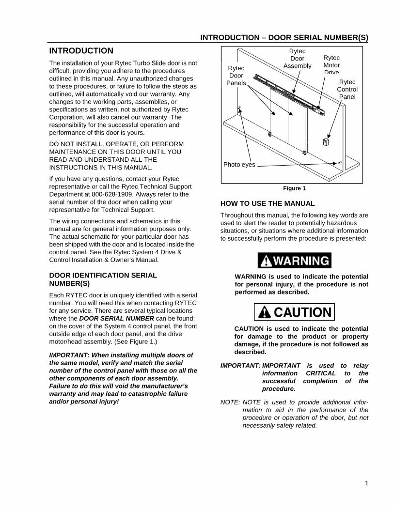
DOOR IDENTIFICATION SERIAL NUMBER(S) Each RYTEC door is uniquely identified with a serial number. You will need this when contacting RYTEC for any service. There are several typical locations where the DOOR SERIAL NUMBER can be found; on the cover of the System 4 control panel, the front outside edge of each door panel, and the drive motor/head assembly. (See Figure 1.)
IMPORTANT: When installing multiple doors of the same model, verify and match the serial number of the control panel with those on all the other components of each door assembly. Failure to do this will void the manufacturer’s warranty and may lead to catastrophic failure and/or personal injury!
Figure 1
HOW TO USE THE MANUAL Throughout this manual, the following key words are used to alert the reader to potentially hazardous situations, or situations where additional information to successfully perform the procedure is presented:
WARNING is used to indicate the potential for personal injury, if the procedure is not performed as described.
CAUTION is used to indicate the potential for damage to the product or property damage, if the procedure is not followed as described.
IMPORTANT: IMPORTANT is used to relay information CRITICAL to the successful completion of the procedure.
NOTE: NOTE is used to provide additional infor-mation to aid in the performance of the procedure or operation of the door, but not necessarily safety related.
Rytec Door
Assembly
Photo eyes
Rytec Control Panel
Rytec Door
Panels
Rytec Motor Drive

2
INSTALLATION – MATERIAL, TOOLS, AND EQUIPMENT
INSTALLATION
MATERIAL, TOOLS, AND EQUIPMENT 1. Threaded rod (Ø3/8 -in. and Ø1/2 -in. diameter)
and other various wall anchor hardware and material. Concrete anchor bolts (Ø3/8 in.-Ø1/2 -in. diameter). (See “ANCHORING METHODS” on page 4.)
2. Assorted shim stock. 3. Double-sided tape (for attaching shims to wall). 4. Carpenter’s level (4-ft. minimum length). 5. Carpenter’s square. 6. Hammer drill. 7. Drill. 8. Torque wrench. 9. Caulk gun & appropriate caulking for
application. 10. Masonry drill bits (for Ø3/8 -in. and Ø1/2 -in.
diameter anchors). 11. Hammer or mallet, and block of wood. 12. Crowbar or pry bar. 13. Assorted hand tools (pliers, tape measure, etc.). 14. Socket and wrench sets. 15. Water level, line level, or transit. 16. Two ladders (taller than height of door opening). 17. Forklift (see “Forklift Requirements” on page 2). 18. Bucking materials (see “Bucking
Requirements”).
ADDITIONAL REQUIREMENTS Labor and Site Requirements
1. Two installers at a minimum. 2. A certified electrician is required for making all
electrical connections. (See the Rytec System 4 Drive & Control Installation & Owner’s Manual.)
3. 100% accessibility to the door opening during the entire installation process. No traffic should be allowed to pass through the opening while the door is being installed.
Forklift Requirements A forklift supplied by the customer, dealer, or installer is mandatory for the safe and proper installation of this door. The forklift should have: ● 2000-pound lifting capacity ● Minimum height ability — door height, plus 12 in. ● side-shift capability (desired)
Electrician’s Responsibilities
For complete details on the responsibilities of the electrician, refer to the Rytec System 4 Drive & Control Installation & Owner’s Manual. Additionally, the heat tape connection(s) are to be done by a certified electrician if provided.
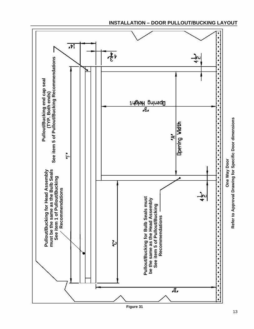
Pullout/Bucking Recommendations Door Pullout, or Bucking, requirements are specifically dependent upon the job site. It is up to the customer/installer to meet applicable code and engineering requirements and provide an appropriate mounting surface for the door. Refer to Figures 30 and 31 for additional layout and dimensional information. Recommendations to follow for door pullout/bucking, if needed, for the door mounting surface:
1. Bucking/pullout material for the door mounting surface must be flush and planar behind the Bulb Seals and Head Assembly.
2. Bucking/reinforcement on the opposite wall side of the Head Assembly is strongly Recommended for framed walls. (Refer to Installation–Anchoring Methods)
3. Bucking/pullout material should be metal clad wood or composite wood.
4. Bucking/pullout behind the Head Assembly hat channel flange faces are required for support of the upper and lower bolting flanges.
5. Seal/Cap off the bucking/pullout between the Head Assembly and mounting wall to enclose the area behind the hat channel.
IMPORTANT: It is CRITICAL to successfully create a mounting surface that is planar, plumb, square, level, and flush for the door to perform properly.

3
INSTALLATION – GENERAL ARRANGEMENT OF DOOR COMPONENTS GENERAL ARRANGEMENT OF DOOR COMPONENTS Figure 2 and Figure 3 show the location of the major components of the door and the general placement of the associated sub-assemblies for a typical installation.
These illustrations are for informational purposes only. They should not be relied upon solely during the installation of your door and its sub-assemblies.
Figure 2a, Exploded View
Figure 2b, Assembled View
IMPORTANT: The surface of the wall to which the door is to be installed must be free of any obstructions and/or perpendicularity - floor, flatness issues. Also, any existing door framing on the wall should be removed. Otherwise the Bulb Seals and/or Head Assembly will require pullout/shimming also known as “bucking”.
Figure 3
NOTE: The above illustrations show the front of the door. Left and right are determined when viewing/facing the front of the door.
IMPORTANT: The Door must be oriented correctly and match the associated official customer approval drawing. It is especially important on One Way Door model(s). This is due to the fact that the head assembly trolley tracks are designed to move the door panel up and away from the bulb seal as it opens. Therefore, proper orientation of the Head Assembly is imperative.
One Way Door
Head Assembly
Insulated Door Panel
Stay Rollers
Rytec Control Panel
Rytec Control Panel
Bulb Seals (Top & Sides
Main Door Assembly
Stay Roller
Head Assembly
Insulated Door Panels
Rytec Control Panel
Photo Eye
4
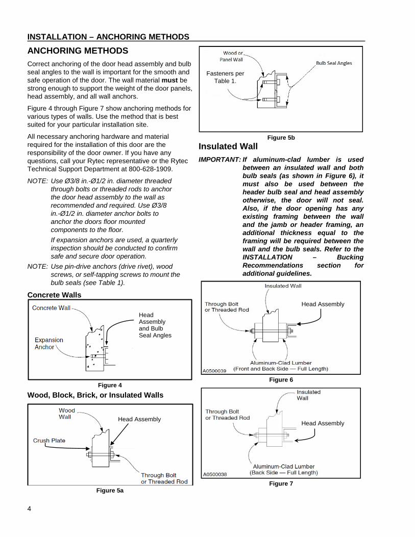
INSTALLATION – ANCHORING METHODS ANCHORING METHODS Correct anchoring of the door head assembly and bulb seal angles to the wall is important for the smooth and safe operation of the door. The wall material must be strong enough to support the weight of the door panels, head assembly, and all wall anchors.
Figure 4 through Figure 7 show anchoring methods for various types of walls. Use the method that is best suited for your particular installation site.
All necessary anchoring hardware and material required for the installation of this door are the responsibility of the door owner. If you have any questions, call your Rytec representative or the Rytec Technical Support Department at 800-628-1909.
NOTE: Use Ø3/8 in.-Ø1/2 in. diameter threaded through bolts or threaded rods to anchor the door head assembly to the wall as recommended and required. Use Ø3/8 in.-Ø1/2 in. diameter anchor bolts to anchor the doors floor mounted components to the floor. If expansion anchors are used, a quarterly inspection should be conducted to confirm safe and secure door operation.
NOTE: Use pin-drive anchors (drive rivet), wood screws, or self-tapping screws to mount the bulb seals (see Table 1).
Concrete Walls
Figure 4
Wood, Block, Brick, or Insulated Walls
Figure 5a
Figure 5b
Insulated Wall IMPORTANT: If aluminum-clad lumber is used
between an insulated wall and both bulb seals (as shown in Figure 6), it must also be used between the header bulb seal and head assembly otherwise, the door will not seal. Also, if the door opening has any existing framing between the wall and the jamb or header framing, an additional thickness equal to the framing will be required between the wall and the bulb seals. Refer to the INSTALLATION – Bucking Recommendations section for additional guidelines.
Figure 6
Figure 7
Head Assembly Head Assembly
Head Assembly
Fasteners per Table 1.
Head Assembly and Bulb Seal Angles

5
INSTALLATION – UNCRATING UNCRATING Your Rytec Door has been shipped in two individual crates. One crate contains the insulated door panels. The second crate holds the head assembly and all other supporting components and hardware necessary to install the door.
NOTE: For minimal handling of components dur-ing the installation of your door, remove the components and sub-assemblies from the crate in which they were shipped, in the order directed throughout this manual.
IMPORTANT: Do not remove the door panel(s) until they can be fully installed. To prevent damage: lay the door panel(s) flat for storage, do not crush the perimeter seals, and do not stack the door panel(s).
1. Remove the top of each crate (See Figures 10-13 & Table 1 for fastener recommendations.)
Figure 8
2. Remove the front panel and both end panels from each crate to expose the door components and other miscellaneous hardware.
LOCATING CENTERLINE OF DOOR OPENING (BI-PARTING DOOR)
NOTE: A bi-parting door requires knowing the location of the centerline of the door opening. Accurate measurements are critical for the proper installation and operation of your Rytec Door. Verify all measurements.
1. Measure the width of the door opening. Then divide the measurement in half to locate the centerline. Mark the centerline along the floor (See Figure 9). Project this location up to the top of the opening via a method that ensures the mark is plumb & square.
Figure 9
DETERMINE PLUMB/SQUARE OF DOOR OPENING 1. Measure and compare the width of door opening
at the top and bottom. Measure the diagonal dimensions of the door also. The top/bottom dimensions and the diagonal dimensions will be identical if the door is square.
2. If the door opening isn’t square adjustments may be required to center the door panel(s) over the door opening.
3. If the wall is not plumb then the head assembly and bulb seals will need to be shimmed.
NOTE: Contact Rytec Customer Support if the floor is more than 1 inch out of level.
Check wall for plumb Check door jamb
for level
Check door edges for
plumb

6
INSTALLATION –BULB SEALS BULB SEALS NOTE: If the head assembly required or will require
shims for installation the bulb seals must also be shimmed and aligned the same or the door will not seal properly.
Bulb Seal Frame 1. Locate the (6) 2” x 2” galvanized angles in the
head crate. Set angles to the side.
NOTE: The angles are not factory pre-trimmed and will need to be modified in the field.
2. Remove the (3) Bulb Seals from the head assembly crate. Bulb seals for the sides are specially cut on one end to fit tightly around the top door jamb bulb seal
3. Trim the inside angles to length to suit the door opening (See Figure 10). Mount the inside 2” x 2” bulb seal angles flush with the door opening as shown. The angle’s hemmed edge leg must be facing away from the wall and the flat edge leg mounted on the wall. Apply Silicon caulking between the galvanized angles and the wall to create an airtight seal. The caulk must be rated appropriate for the installation environment. Fasten angles to the wall every 16 inches using appropriate mounting hardware for your application. After the angles are mounted additionally seal the seams and joints between the angles and wall with a bead of caulk as well (See Figures 10-13 & Table 1 for fastener recommendations.)
Figure 10
Figure 11
Wall Material Recommended Fastener Concrete Pin-Drive Anchor (Drive Rivet)
Wood Wood Screws
Insulated Panel Self-tapping screws
Table 1
Figure 12
Figure 13
4. Fit bulb seal tightly against the inside angle and mark a line to assist positioning the outer galvanized bulb seal angles (See Figure 14).
Figure 14
5. Mount the outer galvanized bulb seal angles following the same procedure as the inside angles. Align the angle edges with the mark(s) you made in the previous step. They should look as shown in Figure 15.
NOTE: The 2 side outer angles are longer then the inside to cover the ends of the top bulb seal. The top angle on the top bulb seal will also be longer.
Inside door angles
Door wall
Outside angle offset for bulb seal width
Mark line to position outer angle
Bulb seal
Hemmed edge
Angle Flat edge
7
INSTALLATION – BULB SEALS
Figure 15
Bulb Seal Installation
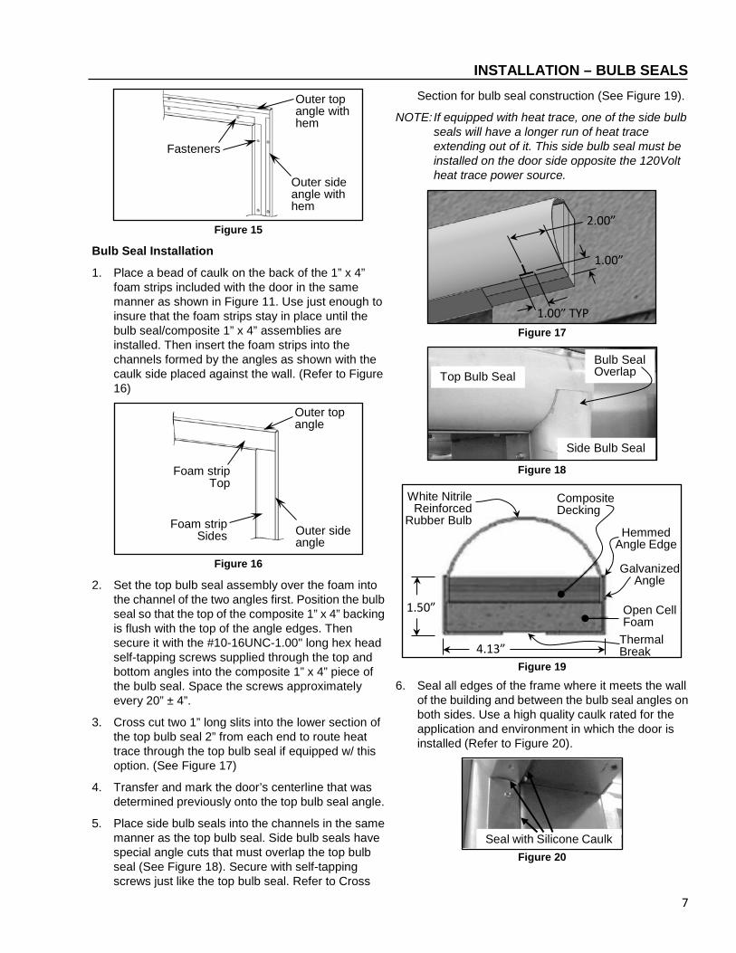
1. Place a bead of caulk on the back of the 1” x 4” foam strips included with the door in the same manner as shown in Figure 11. Use just enough to insure that the foam strips stay in place until the bulb seal/composite 1” x 4” assemblies are installed. Then insert the foam strips into the channels formed by the angles as shown with the caulk side placed against the wall. (Refer to Figure 16)
Figure 16
2. Set the top bulb seal assembly over the foam into the channel of the two angles first. Position the bulb seal so that the top of the composite 1” x 4” backing is flush with the top of the angle edges. Then secure it with the #10-16UNC-1.00" long hex head self-tapping screws supplied through the top and bottom angles into the composite 1” x 4” piece of the bulb seal. Space the screws approximately every 20” ± 4”.
3. Cross cut two 1” long slits into the lower section of the top bulb seal 2” from each end to route heat trace through the top bulb seal if equipped w/ this option. (See Figure 17)
4. Transfer and mark the door’s centerline that was determined previously onto the top bulb seal angle.
5. Place side bulb seals into the channels in the same manner as the top bulb seal. Side bulb seals have special angle cuts that must overlap the top bulb seal (See Figure 18). Secure with self-tapping screws just like the top bulb seal. Refer to Cross
Section for bulb seal construction (See Figure 19).
NOTE: If equipped with heat trace, one of the side bulb seals will have a longer run of heat trace extending out of it. This side bulb seal must be installed on the door side opposite the 120Volt heat trace power source.
Figure 17
Figure 18
Figure 19
6. Seal all edges of the frame where it meets the wall of the building and between the bulb seal angles on both sides. Use a high quality caulk rated for the application and environment in which the door is installed (Refer to Figure 20).
Figure 20
Outer top angle with hem
Outer side angle with hem
Fasteners
Seal with Silicone Caulk
Outer top angle
Outer side angle
Foam strip Sides
Foam strip Top
2.00”
1.00”
1.00” TYP
White Nitrile Reinforced
Rubber Bulb
Composite Decking
1.50”
4.13”
Galvanized Angle
Open Cell Foam
Thermal Break
Top Bulb Seal
Side Bulb Seal
Bulb Seal Overlap
Hemmed Angle Edge

8
INSTALLATION – HEAD ASSEMBLY HEAT TAPE ROUTING 1. If equipped, route the heat tape from the side bulb
seals into the top bulb seal through the slits cut previously in this installation process. Feed both the short and the long leads of heat tape through the top bulb seal so that both leads exit on the same side of the door where the 120v heat tape power supply is located. Electrical connection of the heat tape to be done by a certified electrician.
HEAD ASSEMBLY 1. Prepare to lift the head assembly by removing the
sides of the crate.
For added stability, spread the forks as wide as possible. Then carefully load the head assembly onto the forklift so that the head is in its normal, upright position. Securely fasten the head assembly to the forklift before lifting it into position. Failure to safely secure the head can result in damage to the door and cause serious personal injury.
DO NOT remove the forklift from under the head assembly until the head assembly is securely fastened to the wall.
2. With a forklift or other suitable lift, remove the head assembly from the shipping crate following all safety warnings described above. Secure the head assembly to the forklift using clamps or another suitable method. (See Figure 21 & 23) Check that the chain is properly routed around and through all the gears and guide tensioners.
Figure 21
3. Lift the head above the door opening. Horizontally position the head assembly according to Table 2 below. Orient and position the door to match the official customer approval drawing.
Figure 22
Figure 23
Door Style Header Positioning Bi-parting Align chain reverser/track center
with door opening centerline. Single Slide Align header edge flush with
outer bulb seal channel. Table 2
4. Vertically position the head assembly 3/4” to 7/8” above the top bulb seal channel (See Figure 22). Make sure it is level, plumb, and square w/ the door opening. Shim the assembly as required so it mates with the bulb seal. (See Figure 21) Insure no debris gets in the J-rails or on the drive chain and its components.
5. Fasten the head assembly to the wall. Anchor the head in all 4 corner anchor holes and then at least every other anchor hole along the top and bottom of the header flange with the appropriate fasteners. (See Table 3)
6. Clean all debris off and out of the J-rail brackets the trolleys travel in.
Wall Material Recommended Fastener Concrete Ø3/8” Diameter Stud Anchor
for Concrete Wood or Panel
Ø3/8” All-thread bolted through wall with large washer on backside. (Note: Use Silicon Caulking to create airtight seal on freezer side)
Table 3
Check for Plumb
Check for Level
Align chain reversing center with door opening centerline
Gap to be ¾” to 7/8”
Clamps

9
INSTALLATION – PANEL INSTALLATION PANEL INSTALLATION 1. Remove the door panel(s) from the crate and
position it with the Manual Release Handle facing into the wall opposite the side of the wall that the door’s System 4 controller is being installed on as shown. Stand the panel against the opening. (See Figures 24a and 24b)
Figure 24a Figure 24b
2. Attach the door panel(s) to the trolley hangers using the Ø1/2” clevis pin to mate the swivel hanger bracket (pre-mounted on the door panel) with the swivel hanger barrel nut attached to the trolley. With the door panel(s) in the closed position, loosen the 3/8” flange bolts securing the swivel hanger brackets to the door panel(s). Adjust the offset of the door(s) so it is parallel to the wall and is equally compressing the top bulb seal ¼” to ½”. On Bi-Parting doors both panels must align and form a tight center seal. Add a ᴓ1/4”-ᴓ3/8” patch of Loc-Tite™ Blue to the bolt threads prior to final installation locating the patches so they will fully engage the threads of the mating fasteners. Torque bolts to 15 FT-LBS utilizing a figure 8 pattern. (See Figures 25a and 25b)
Figure 25a
3. Level the panel(s) using the large trolley bolts. Use a 1-1/8” wrench to adjust the height of the door panel(s). Raise or lower the panel(s) so the bottom skirt is just touching the floor when closed.
4. Tighten the jamb nut on the large trolley bolt to trolley carriage. Torque jamb nut to 15FT-LBS.
Figure 25b
Figure 26a
Figure 26b
NOTE: The trolley bolt jamb nut must be tightened as specified. Failure to do so will cause damage.
5. Attach door panel(s) to the chain bracket(s) with 3/8”-16 UNC x 2” long flange head bolts included in the door panel. Align and level the chain bracket(s) so the chain is aligned with the sprockets, is level with the chain, and insure the chain bracket does not rub on the J-rail. Add a Ø1/4”-Ø3/8” patch of Loc-Tite™ Blue to the bolt threads prior to installation locating the patches so they will fully engage the threads of the mating fasteners. Torque bolts to 15 FT-LBS. (See Figure 26a & 26b)
6. Attach the door/chain release cable; each door is equipped with a safety release handle. Wrap the chain release cable around the top two bolts in a figure 8 pattern as shown. Torque the bolts to 4 FT-LBS to prevent cable from slipping while in use. Test the handle to determine if the release is working properly. Adjust as needed. (See Figure 27)
NOTE: Proper operation requires a ¼ to ½ turn of the safety release to actuate the chain release.
Figure 27
Position brackets on door so they mate correctly with bulb seal
Manual Release Handle
Door controller mounted on opposite
side of wall.
Chain release assembly bracket on drive chain
Mounting door panel to chain release assembly bracket on drive chain
Mounting door panel to swivel hanger brackets
Swivel Hanger Bracket Clevis Pin

10
INSTALLATION – STAY ROLLERS, PHOTO EYES, & TROUBLESHOOTING STAY ROLLER INSTALLATION 1. Install Stay Rollers – With the door in the closed
position, hanging free and plumb, place the stay rollers so they are just touching the panel on the outside of the door opening jamb clear of the door opening and opposite the jamb. This will create a slot for the door panel(s). (See Figure 28 and 29)
NOTE: The F0091 Stay Roller is for mounting on the leading edge of single slider doors when applicable.
2. Attach to the floor using ؽ” diameter stud anchor for concrete. Center the anchors in the bracket, if possible. To allow for future adjustment of the roller. Once the anchors are installed, slight pressure should be against the door with the roller.
3. Confirm that the bulb gasket behind the door panel is not compressed too far. Compression should be ¼” to ½” of the bulb seal.
Figure 28
Figure 29
PHOTO EYE INSTALLATION The Turbo Slide door ships with 1 set of safety photo eyes. 2 sets can be purchased as an option. One set for the front of the door and one optional for the rear. Interruption of either photo eye set will cause the door to remain open. If the door is closing and the
photo eye beam is interrupted the door will reverse and re-open. Proper alignment is indicated by the yellow light on the receiver. The transmitter will have a green light indicating the transmitter is receiving power.
NOTE: The photo eyes are not intended to be used as a door activator and will not open the door when it is closed.
1. Locate the photo eyes, mounting brackets, and cables in the small parts carton.
NOTE: Choose appropriate mounting hardware required for your installation for the photo eye brackets.
NOTE: To ensure the photo eyes are properly aligned, their mounting brackets must be directly across from each other and level.
2. Mount the safety photo eyes 18”-24” high across the door opening. Recommend placing the front and rear sets at different heights.
3. Route photo eye cables back to the System 4 control panel. Conduit should be used to route the photo eye cables back to the control. Trim excess cables to length and make electrical connections in the System 4 control panel.
NOTE: Route the cables away from any moving parts and sharp corners.
ELECTRICAL SYSTEM NOTE: Refer to the Rytec System 4 Drive & Control
Installation & Owner’s Manual for electrical system wiring.
TESTING PHOTO EYES Once power is applied, the green light indicates the photo eye transmitter module is powered up. When the yellow light on the receiver module is also lit, the transmitter and receiver modules are properly aligned.
Placing your hand in front of either photo eye breaks the path and causes the yellow light to go out on the receiver. Removing your hand causes the yellow light to go back on.
PHOTOEYE TROUBLESHOOTING If either green light is not lit, check to make sure that power is turned on and that all wiring has continuity and is installed correctly. If the green lights are on but the yellow light is off, check the alignment of the transmitter and receiver modules. Also, clean the lens of each photo eye using window cleaner and a soft, clean cloth.
Anchor base to concrete
through slots
Align stay roller with door jamb
Door Opening Wall
Stay Roller Base
Approx: 9” (R17-4” Thick Panel) 11” (R25-6” Thick Panel)
F81 Stay Roller Bracket Placement
9” (R17-4” Thick Panel) 11” (R25-6” Thick Panel)
Anchor base to concrete
through slots
Offset stay roller from door
jamb
Door Opening Wall
Stay Roller Base for Right Hand
Door F0091 Universal Cam Stay Roller Bracket Placement
Wall
Stay Roller Base for Left Hand
Door
3/8” TYP.

11
INSTALLATION – DOOR LIMIT POSITIONS DOOR LIMIT POSITIONS
Improperly adjusted open and close limits can result in damage to the drive system.
NOTE: To set the close and open limits, refer to the Rytec System 4 Drive & Control Installation & Owner’s Manual.
BI-PARTING DOOR CLOSE LIMIT
1. Turn on the power and the close the door.
2. Check the spacing between the door panels. The seals should interlock and be slightly compressed. The amount of seal compression should be the same and equal from the top to the bottom of the door panels by 1/4”-1/2”.
3. If the fully closed position requires adjustment, refer to the Rytec System 4 Drive & Control Installation & Owner’s Manual and adjust as required.
4. If there is a gap or the seal compression is not the same at the top and bottom, check the door panel alignment. Mechanically adjust as required.
OPEN LIMIT
1. Turn on the power and open the door.
2. Check the fully open position. The panels should be even with or just beyond the door opening jambs. If not, refer to the Rytec System 4 Drive & Control Installation & Owner’s Manual and adjust as required.
ONE-WAY DOOR CLOSE LIMIT
1. Turn on the power and then close the door.
2. Check the spacing between the leading edge of the door panel and bulb seal. The seal should be slightly compressed equally from the top to the bottom of the door panel by 1/4”-1/2”.
3. If the fully closed position requires adjustment, refer to the Rytec System 4 Drive & Control Installation & Owner’s Manual and adjust as required.
4. If there is a gap or the seal compression is not the same at the top and bottom, check the door panel alignment and mechanically adjust as needed.
OPEN LIMIT
1. Turn on the power and then open the door.
2. Check the spacing between the trailing edge of the door panel and the door jamb. The panel should be even or just beyond the door opening jamb.
3. If the fully open position requires adjustment, refer to the Rytec System 4 Drive & Control Installation & Owner’s Manual.

12
INSTALLATION – DOOR PULLOUT/BUCKING LAYOUT
Figure 30
Bi-Parting D
oor R
efer to Approval D
rawing for Specific D
oor dimensions
Pullout/Bucking end cap seal
(TYP. Both ends)
See item 5 of Pullout/B
ucking Recom
mendations
Pullout/Bucking for H
ead Assem
bly must be the
same as the B
ulb Seals See item
1 of Pullout/Bucking R
ecomm
endations
Pullout/Bucking for B
ulb Seals m
ust be the same as
the Head A
ssembly
See item 5 of
Pullout/Bucking
Recom
mendations
13
INSTALLATION – DOOR PULLOUT/BUCKING LAYOUT
Figure 31
Pullo
ut/B
ucki
ng fo
r Bul
b Se
als
mus
t be
the
sam
e as
the
Hea
d A
ssem
bly
See
item
5 o
f Pul
lout
/Buc
king
R
ecom
men
datio
ns
Pullo
ut/B
ucki
ng e
nd c
ap s
eal
(T
YP. B
oth
ends
) Se
e ite
m 5
of P
ullo
ut/B
ucki
ng R
ecom
men
datio
ns
One
Way
Doo
r R
efer
to A
ppro
val D
raw
ing
for S
peci
fic D
oor d
imen
sion
s
Pullo
ut/B
ucki
ng fo
r Hea
d A
ssem
bly
mus
t be
the
sam
e as
the
Bul
b Se
als
See
item
1 o
f Pul
lout
/Buc
king
R
ecom
men
datio
ns
14
INSTALLATION – FINAL CHECKS
FINAL CHECKS NOTE: Check the following door systems and
components after the door panel has been cycled at least 20 times.
Head Assembly: Check that all mounting hardware is in place and tight.
Insulated Panels: ensure that the insulated panels travel smoothly, are adjusted to seal tight against the floor and the bulb seals. Check that all hardware is in place and tightly secured.
Door Seal: The door seals between the back of the insulated panel and the bulb seals around the perimeter of the panel.
NOTE: Compression of the seal ¼” to ½” on all contact points.
Motor: Check that the door travels in the proper direction when the control button is pressed. Also check that the motor operates smoothly and quietly.
Photo Eyes: Check that the photo eyes operate as described in “PHOTO EYES” on page 10.
Timers: Automatic timers must be set to ensure that the door closes properly, as described in the Rytec System 4 Drive & Control Installation & Owner’s Manual.
Activators: Check that the activators operate as specified by the manufacturer.
Heat Tape: The self-regulating thermal heat tape will be warm to the touch when powered up.
Open and Close Limits: Check open and close limits. See “Door Open and Close Limit Positions” on page 10.
Caulk: Ensure that all edges of the jamb and angles are sealed where they meet the wall of the building. Use a high-quality caulk rated for the application/environment in which the door is installed, as required.
Door Panel Stay Rollers: The stay rollers properly align the panel to create a seal around the perimeter of the door panel. If the door has the breakaway stay rollers for impact, make sure they also provide a seal around the perimeter against the bulb seals.

15
INSTALLATION – NOTES