turbomachinery airfoil design optimization using ...€¦ · turbomachinery airfoil design...
TRANSCRIPT

_ill _" :"i
Turbomachinery Airfoil Design Optimization
Using Differential Evolution
Nateri K. Mada,'an
NASA Advanced -;upercomputing Division,NASA Ames Res_ _rch Center, Moffett Field, CA 94035-1000, USA
Abstract. An a( r(,dynamic design optimization procedure that is based on a evolu-tionary algorithm known at Differential Evolution is described. Differential Evolutionis a simple, fast, md robust evolutionary strategy that has been proven effective indetermining the gkd)al optimum for several difficult optimization problems, includinghighly nonlinear s .:stems with discontinuities and multiple local optima. The method iscombined with a %vier-Stokes solver that evaluates the various intermediate designs
and provides inp_ ts to the optimization procedure. An efficient constraint handlingmechanism is als(b incorporated. Results are presented for the inverse design of a tur-bine airfoil from ._ modern jet engine. The capability of the method to search largedesign spaces and obtain the optimal airfoils in an automatic fashion is demonstrated.Substantial redu( ions in the overall computing time requirements are achieved byusing the algoritb n in conjunction with neural networks.
1 Introduc t.ion
Remarkable prot ress has been made in recent years in the ability to design tur-
bomachinery airfoil shapes that are optimal with regard to certain desired char-
acteristics. This m)gress has been achieved by combining improved methods for
predicting the c(,mplicated flow fields in turbomachinery with efficient numerical
optimization tec!miques and by harnessing the powerful capabilities of modern
computers. Both steady and unsteady Navier-Stokes and Euler solvers have beencombined with v._rious optimization techniques (gradient-based methods [1], [2],
response surface:., _tc.) to optimize the design of turbomachinery airfoils.
More recentl>, there has been considerable interest in the development of tur-
bomachinery airtoit design optimization techniques that are based on nontradi-
tional approache _such as evolutionary algorithms and neural networks. Variousapproaches base, I on neural networks (see, for example, [3], [4], [5]), neural net-
works in conjun, tion with response surfaces [6], [7], genetic algorithms [8], [9],
and genetic alg(,cithms in conjunction with neural networks [10],[11],[12] have
been reported in the literature. These techniques offer several advantages over
traditional optin iz._tion methods.
This paper d ',als with the development of a turbomachinery airfoil design
optimization pro :edure that is based on a relatively new evolutionary algorithm
known as Differ(' lt.ial Evolution [13] developed for single-objective optimizationin continuous se_r(:h spaces. It is conceptually simple and possesses good conver-
gence properties _hat have been demonstrated in a variety of applications. Dif-
ferential Evoluti,,n (DE) is best characterized as an evolutionary strategy (ES)
https://ntrs.nasa.gov/search.jsp?R=20020073236 2020-05-02T16:28:24+00:00Z

2 NateriK Madavan
ratherthan as a _enetic algorithm (GA), although the distinction between GAs
and ESs has blm red in recent years. Perhaps the main ideological difference lies
in the relative i_t_portance given to the two main evolutionary operators, recom-
bination (crosso'er) and mutation, with GA-based approaches relying heavily
on the former at,d ES-based approaches on the latter. DE has proven to be an
effective approa_ h in determining the global optimum for several difficult opti-
mization problems in a variety of applications. Its application in aeronautics,
however, has be,,n rather limited. It has been used in the predictive control of
aircraft dynamic s 114]. DE has been used in conjunction with a potential flowsolver in the imerse design of turbomachinery airfoils [15]; the same authors
have also presem;ed a hybridized version [16] that combined DE with a localsearch method t _minimize the number of objective function evaluations using
the potential flow solver.In this paper the DE algorithm is combined with a Navier-Stokes solver
that provides inl,uls to the optimization procedure. An efficient constraint han-
dling mechanisr_ is also incorporated in the algorithm. An airfoil geometryparametrization hat uses a minimal number of variables is also used to minimize
the number of (,!_.jective function evaluations. The procedure is also combined
with neural neta, otks that are incrementally trained on the Navier-Stokes sim-ulation data an( (an then be used in the objective function evaluation. This
results in subst>ntial reductions in the overall computing time. Additionally,
the procedure h._.s been implemented on a distributed parallel computer in a
straightforward manner that relies on the simultaneous computation of multi-
pie, independent aerodynamic simulations on separate processors. The procedureis primarily scril_t-based and allows for a variable number of processors to be
used depending ,,n the size of the population used in the DE algorithm. Details
of the method aud its implementation and results for the inverse design of a
turbine airfoil to demonstrate its capabilities are described.
2 Design Optimization Method
The main ingredim_ts of the design optimization method are discussed in this sec-tion. The DE alg, ,rithm, the airfoil geometry parametrization procedure, and the
CFD flow solver _lsed for evahmting the objective function are discussed briefly.
Some details reg_ rding the implementation of the method on parallel distributed
computers are al _o provided. A hybrid version that helps reduce computational
cost by combiniHg he DE algorithm with a neural network approach is alsodescribed.
2.1 Differential Evolution
Differential Evoh lion is an ES-based approach developed for single-objective op-
timization in coJ tinuous search spaces. It is conceptually simple and possesses
good convergenc, properties that have been demonstrated in a variety of appli-
cations [18]. Details of the algorithm can be found elsewhere [13], [17]; only itsmain features arc summarized here.

TurbomachineryAirfoilDesign Optimization 3
The approach uses a population PQ that contains N K-dimensional real-
valued paramete "vectors in generation Q, where K is the number of parametersor decision varia!,l(s:
PQ = P/Q =P_k, i= 1,..,N ; k = 1,...,K (1)
The populati, _n is usually initialized in a random fashion and the population
size N is maintained constant throughout the optimization process. Differentialevolution is thu_ similar to a (# + _) ES [19] with tt and _ equal to N [20].
The method hov, _'_verdiffers from standard ES approaches in several respects as
described below.
As with all E_;-based approaches, mutation is the key ingredient of differential
evolution. The b_ sic idea is to generate new parameter vectors for the subsequent
generation by us ng weighted differences between two (or more) parameter vec-tors selected raJJdomly from the current population to provide appropriately
scaled perturbati ms that modify another parameter vector (or, comparison vec-
tor) selected fron the same population. This idea has been implemented invarious forms bu the form discussed and used here is the classical implementa-
tion where new lcial parameter vectors Pi?+1 for the next generation Q + 1 aregenerated according to the following mutation scheme:
where
j}Q+I _Q Q pQi,k = t_,,k +F'(pb,,k- _,,k) , i=I,...,N; k=l,...,K (2)
a, b, ce {1,...,N} ; aiCbi¢ciCi
The integers t.,, hi, and ci represent three random individuals of the popu-
lation that are n utually different from each other and from the running index
i. The mutation parameter F E [0, 2] is a real, constant, user-supplied param-
eter that control,; the amplification of the differential variation. Other variantsthat either use tl:e difference between more than two parameter vectors or keep
track of the best mrameter vector at each generation and use it in the mutation
scheme have als( been developed [9] and used with varying success in specific
applications. The;s, differential evolution differs from other ESs most notably inthat the mutatio _ operator is derived from the current population and not by
probability densi,y functions that are defined separately.DE is similar to other reeombinative ES approaches in that it also uses dis-
crete recombination. While various recombination strategies exist [19] the strat-
egy adopted in , igerentlal evolution is to modify the trial parameter vectorsg_)C_+ I
i as follows:
/3Q+a =/5 Q+I if ri,k <Cr or k=dk (4)i,k i,k --
and
ii_Q+l ----- PQi.k otherwise (5)i,k

4 Nateri K. Madavan
In the above,, 7" E [0,1] is a uniform random number, CT C [0,1] is the
crossover parant, t_er, and dk is a randomly chosen index in {1, ..., K} that ensures
that/5 Q+I gets a least one parameter from the mutated/5 Q+t and not all fromi,k i,k
P_k" Note also tttat the mutation and recombination operations described abovecan lead to new v(.ctors that may fall outside the boundaries of the variables.
Various repair r,lles can be used to ensure that these inadmissible vectors do
not enter the poimlation. A simple strategy, which is the one adopted here, isto delete these imLdmissible vectors and form new ones until the population is
filled.The selectiot_ s,:heme used in DE is deterministic but differs from methods
usually employec i in standard ES approaches. Selection is based on local com-
petition only, wil h the child trial vector (or, child)/SiO+l competing against one
population member P/Q (the comparison vector) and the survivor entering the
new population ,_¢!+1 . In other words, if/5/Q+1 yields a better objective func-
tion value than ,'_,_' then pQ+l is set to /SiQ+1. Otherwise, the old value PiQ is
retained. This gr.,edy selection criterion results in fast convergence; the adaptivenature of the mutation operator, in general, helps safeguard against premature
convergence and al!ows the process to extricate itself from local optima.An efficient c )nstraint handling mechanism has been incorporated into the
algorithm. Detaits are given elsewhere; briefly, it is a parameter-less penaltyfunction approa, h where infeasible solutions are penalized and help guide the
algorithm away from these regions. Physical constraints, e.g., maximum airfoil
thickness, etc., ae imposed, as well as aerodynamic constraints (wavy surfaces,
etc.). Airfoil geo,_mtries that meet the constraints but for which the CFD solver
is unable to con 'erge or "blows up" are also deemed infeasible and penalized
accordingly.
2.2 Airfoil Ch_ometry Parametrization
Geometry parametrization and prudent selection of design variables are amongthe most critical :_.sl)eets of any shape optimization procedure. The ability to rep-
resent various airfoil geometries with a common set of geometrical parameters
is essential. Vari,tions of the airfoil geometry can be obtained then by smoothly
varying these pa_ ameters. Geometrical constraints imposed for various reasons,
such as structural, aerodynamic (e.g., to eliminate flow separation), etc., shouldbe included in t}tis parametric representation as much as possible. Addition-
ally, the smallesl n71mber of parameters should be used to represent the familyof airfoils. Here, the airfoil geometry parametrization method described in [6]
that uses a total )t" 13 parameters to define the turbine airfoil geometry is used.
Figure 1 illustrai es the method for a generic airfoil. The geometric parametersused are the lea(ling edge and trailing edge airfoil metal angles (2 parameters),
eccentricity of ul [mr leading edge ellipse (1 parameter), angles defining the ex-
tent of the leadh_g edge ellipses (2 parameters), semi-minor axes values at the
leading edge (2 p.trameters), angles defining the extent of the trailing edge circle
(2 parameters), _ Moil y-coordinate values at about 50% chord on the upper and
TurbomachineryAirfoilDesignOptimization 5
lowersurfaces(2parameters),andairfoily-coordinatevaluesatabout25%and75% chord on th., _pper surface (2 parameters).
2.3 Flow Soher for Objective Function Evaluation
A two-dimensional Navier-Stokes solver is used to perform the flow simulations
(direct function ,v_luations) that serve as inputs to the optimization process.Multiple grids at,, used to discretize the flow domain; an inner "0" grid that con-
tains the airfoil ;rod an outer "H" grid that conforms to the external boundaries
as shown in Fig. :3 The flow parameters that are specified are the turbine pres-
sure ratio, inlet t_mlperature and flow angle, flow coefficient, and unit Reynoldsnumber based oi_ inlet conditions.
2.4 Parallel l:nplementation Details
In order to redm e overall design time, the procedure has been implemented on
distributed paratle[ computers. The results in this article were obtained on the
SGI Origin 3000 _md the Cray SV1 at NASA Ames Researach Center. The imple-mentation of the method is quite straightforward and relies on the simultaneous
computation of z_m]tiple, independent aerodynamic simulations on separate pro-cessors. The proc,'.dure is primarily script-based and allows for a variable number
of processors to be used depending on processor availability and the size of the
population used in the DE algorithm. The number of processors can also be
adjusted as the design proceeds. The current setup is based on a "master-slave"
arrangement, wi_ h the master handling the tasks of setting up the simulations,neural network lraining for the hybrid method, and farming out of the aero-
dynamic compul ttions to the other "slave" processors. Since the aerodynamic
computations ar, it_.dependent of each other, no communication between the pro-
cessors is requir_ 3 until the computations are completed. The slave processorsthen communicaT e 1,heir results to the master which then performs the necessary
calculations to d,'Wrmine the members of the next population.
2.5 Hybrid Difl'erential Evolution-Neural Network (DE-NN)
Approach
While the DE al,:orithm is quite efficient in terms of exploring the entire design
space in its searct for the optimum solution, there is a tendency for the algorithmto slow down aft_ r it approaches the vicinity of the optimal solution and several
function evaluati, m_ are required in order to obtain the exact optimal solution.
This can be reme, tied by a hybrid approach that combines the DE algorithm withneural networks l hat are incrementally trained on the Navier-Stokes simulation
data. The traine l neural network can then be used to evaluate the objective
function evaluati,_n with little or no computational expense instead of using the
Navier-Stokes s_l _,_r. While hybridization is always useful, it must be done with
caution. Here we r_ort to it only in the latter stages after the entire population

6 Nateri14.k_adavan
hasevolvedto _hegeneralvicinityof the optimalsolution.Thusthe neuralnetworkisused+,sa"local"responsesurfacewithvalidityonlyinasmallregionofthedesignspa,e.Thismakesit easiertotraintheneuralnetworkandimprovesits generalization+abilities.
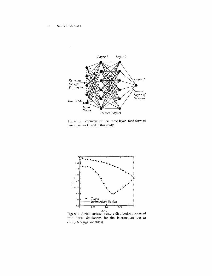
Theresultso_tainedin thisarticlewereobtainedusinga feed-forwardneu-ral networkwith twohiddenlayersasshownin Fig.3. Thefirst nodein theinputlayerisabia,,',node(inputof1.0)andtheremaininginputnodesareusedto specifythewriousdesignparameters.Forthe inversedesignoptimizationproblem,theneur_dnetworkis trainedonthesum-of-squareserrorbetweentheactualpressureamdthetargetpressureat variouspointsontheairfoil.Forthesakeofbrevity,d+_tailssuchasthenumberofneuronsineachlayer,etc.arenotincludedhere.
3 Results
The design met] od was used in the inverse design of a turbine airfoil with a
specified pressm,, distribution. The target pressure distribution was obtained
at the midspan ,,f a turbine vane from a modern jet engine and was supplied
by Pratt and WI,itney (Private Communication, F. Huber, 1997). Several flow
and geometry pa_ ameters were also supplied and used in the design process. The
design objective tunction was formulated as the equally-weighted sum-of-squareserror between th, target and actual pressure obtained during the optimization
process at 45 lo( Ltions on the airfoil.The initial dedgn space was chosen to be quite large to allow for a wide range
of airfoil shapes 1 ) be explored. In order to hold the CFD function evaluations to
a reasonable nun,her, 6 (instead of 13) design variables were used in the initial
stages of the desi 4n. The population of 50 members were then evolved using the
DE algorithm. _f!t('+DE mutation and crossover parameters were both chosen tobe 0.8 based on ,rior experience with other problems; no attempts were made
to optimize thes, _parameters. Figure 4 shows the pressure distribution for an
intermediate airfl,il that represents the best airfoil obtained after 10 generations
using the DE optimization method. The algorithm is able to approach the tar-
get distribution wi1_hin roughly 500 function evaluations (note that the actualnumber of functi+)n evaluations is much less, because many of the initial airfoil
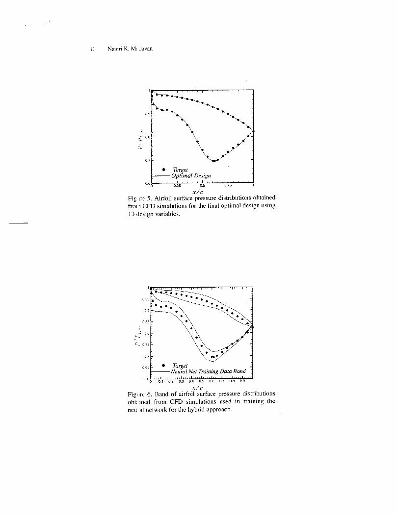
geometries that _,ere infeasible were not evaluated by the CFD solver. After 10generations, the m_mber of design variables is increased to 13 and the popu-
lation evolved fu ther. As is typical with other genetic algorithms, once in the
vicinity of the ol_timal solution, convergence of the DE algorithm slows down
considerably. Th,, tinal design shown in Fig. 5 was obtained after another 10
generations.In order to r, duce the computational cost of the CFD function evaluations
the population atl.er the first 10 generations was used to train a neural network.
Figure 6 shows lh_ band around the target pressure distribution in which allthe data used to _rain the neural network lie. Note, however, that the network
was trained dire( 1_ on the sum-square-error and not on the individual pressure
Turbomachinery Airfoil Design Optimization 7
data. The data ,and in Fig. 6 gives an idea of the local nature of the neural
network respon', '. surface in the vicinity of the optimal solution. The trained
neural network ,vas used in lieu of the CFD solver to perform the function
evaluation with negligible computational cost. The final design obtained was
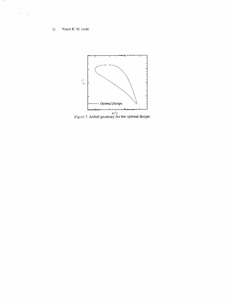
close to that shoa'n in Fig. 5. Finally, Fig. 7 shows the optimal airfoil geometry
obtained by the DE algorithm.
Attempts to ,luantify the computational costs and obtain more detailed eval-
uation of the vat i(,us parameters are currently underway.
4 Summary
An aerodynamic design optimization procedure that is based on a evolutionary
algorithm know_ al; Differential Evolution is described. The method is combined
with a Navier-S1 )kes solver that evaluates the various intermediate designs and
provides inputs 1,(_ the optimization procedure. Results are presented for the
inverse design ot a turbine airfoil from a modern jet engine. The capability of
the method to s _arch large design spaces and obtain the optimal airfoils with
a reasonable number of CFD function evaluations in an automatic fashion is
demonstrated. _1he airfoil geometry parametrization and constraint handling
procedure helps infit the number of CFD function evaluations required by dis-
allowing airfoil !;eometries that are infeasible from a physical or aerodynamic
standpoint. Sub>tantial reductions in the overall computing time requirements
are achieved by 1he hybrid DE-NN algorithm that uses a neural network trained
on the CFD dat L to evaluate the objective function in the latter stages of the
design evolution
References
1. S. Y.Lee, K. 5 . Kim: 'Design Optimization of Axial Flow Compressor Blades with
a Three-Dimensional Navier-Stokes Solver'. Proceedings of the ASME Turbo Expo
2000, Munich, Germany, May 8-11, 2000
2. J. M. Janus, J C. Newman: 'Aerodynamic and Thermal Design Optimization for
2-_rbine Airfoi s'. AIAA Paper No. 2000-08_0, Jan. 2001
3. J. M. Sanz: 'D,.vdopment of a Neural Network Design System for Advanced Turbo-
Engines'. _th t r.S. National Congress on Computational Mechanics, San Francisco,
CA, Aug. 199"
4. M. M. Raft 'A Rapid Aerodynamic Design Procedure Based on Artificial Neural
Networks'. Alia Paper No. 2001-0315, Jan. 2001
5. S. Pierret, R. \. V. Braembussche: Journal of T_rbomachinery, 121, 326 (1999)
6. M. M. Rai, N. K Madavan: AIAA Journal, 38, 173 (2000)
7. N. Papila, W. Shyy, L. Griffin, D. J. Dorney: 'Shape optimization of supersonic
turbines using response surface and neural network methods'. AIAA Paper No.
200I-i065, Ja_. 2001
8. S. Obayashi, S Takanashi: AIAA Journal, 34, 881 (1996)
9. B.H. Dennis, J N. Egorov, Z. X. Han, G. S. Dulikravich, C. Poloni: 'Multi-Objective
Optimization ( f _Purbomachinery Cascades for Minimum Loss, Maximum Loading,
and Maximum (;ap-to-Chord Ratio'. AIAA Paper No. 2000-_,876, Sept. 2000
8 Nateri K Madavan
10. D. Quagliarel a, A. D. Cioppa: 'Genetic Algorithms Applied to the Aerodynamic
Design of Tra,,s(,nic Airfoils'. AIAA Paper 94-1896-CP, 1994
11. M. Uelschen. M. Lawerenz: 'Design of Axial Compressor Airfoils with Artificial
Neural Netwo_ ks and Genetic Algorithms'. AIAA Paper No. 2000-25_6, June 2000
12. C. Poloni, A. 2iurgevich, L. Onesti, V. Pediroda: Comp. Meth. Appl. Mech. Engr.,
186, 403 (200))
13. 1_. Storn_ K. :)rice: Dr. Dobb's Journal, 22, 18 (1997)
14. K. Nho, R. I_; Agarwal: 'Fuzzy Logic Model-Based Predictive Control of Aircraft
Dynamics Usi Lg ANFIS'. AIAA Paper 2001-0316, Jan. 2001
15. T. Rogalsky. [_. W. Derksen, S. Kocabiyik: Can. Aero. Space Inst. Jour., 46, 183
(2000)
16. T. Rogalsky, R W. Derksen: 'Hybridization of Differential Evolution for Aero-
dynamic Desi _,n. Proceedings 8th Ann. Conf. Comp. Fluid Dyn. Soe. Can., pp.
729-736, Jun, ti-13, 2000
17. K. V. Price: ' Differential Evolution: A Fast and Simple Numerical Optimizer'. In:
Biennial Con./erence of the North American Fuzzy Information Processing Society,
(NAFIPS), ,l¢_rm 1996, ed. by M. Smith, M. Lee, J. Keller, J. Yen (IEEE Press,
New York 1996) pp. 524-527
18. J. Lampinen: A Bibliography of Differential Evolution Algorithm. Technical Re-
port. Lappeei, vanta University of Technology, Department of Information Technol-
ogy, Laboratoy of Information Processing, Lappeenranta, Finland (2001)
19. T. Back, U. t ammel, H.-P. Schwefel: IEEE Transactions on Evolutionary Compu-
tation, 1, 3 (1[}97)
20. M. A. Shokr, Ilahi, R. Storm 'Design of Efficient Erasure Codes with Differential
Evolution'. In ['roceedings of ISIT 2000, International Symposium on Information
Theory, Sorr_ ,_to, Italy, June 25-30, 2000

9 Nateri K. M; d_wan
.. x, Yu
x, (Q 2 I 1 I 7 I
O. 0 0.75 1.00 1.25-0.25 t 5)) 0.25 x./Sc_
Figure 1. Schen atic of a generic airfoil showing location of control points on the
airfoil surface a id the defining angles used in the parameterization of the airfoil
geometry.
_--_ i i_ !_:_:_i_,.---___Airfoil
ii-_-__- I !iiiiii=. _ _=- -- i_lll I I 1 l
()uter H-Grid __
Inner O-Grid9-Grid "_ :,,,_::,,,,,,,_ _ I--
llh"llIl', I 1 1
Fig_re 2. Representative turbine airfoil geometry and
con putational grid used in the CFD simulations.
10 Nateri K. M_davan
Layer 1 Layer 2
Relevant yer 3
De,,ign ---'_Pap ameters ;'_
] J/Output/ / Layerof
Node _ NeuronsBia ,
InputNodes
Hidden Layers
Fig_re 3. Schematic of the three-layer feed-forward
neu_ al network used in this study.
II 1 I I I ' ' I I I .... 1 _ ' '
0 96
[)9
085
• ..2 ll8,k.
::,-075
(1.7
oss • Target-- Intermediate Design
(,,_ _- .... 0i5. .... 0 |.5 ......... 0.75
x/cFigt re 4. AiHbil surthce pressure distributions obtainedfron_ CFD simulations for the intermediate design
(using 6 design variables).
11 Nateri K. M: davan
0.9
0.8
0.7
• Target-- Opttmal Design
0.6 i t i i I i i , , I , , , , I , i i J0.25 0.5 0.75
x/c
Fig Lre 5. Airfoil surface pressure distributions obtained
fro_ 1 CFD simulations for the final optimal design using
13, lesign variables.
LL95
0,9 •
C.85
.-: 0.8
E, C.75
D,7
o85 • Target• --Neural Net Training Data Band
_'6i' " '0'.,' ' _0'.2" 0'_;' _'_i'__;'._' "01_" ;'._" '0'.8";'.9"x/c
Fig,re 6. Band of airfoil surface pressure distributions
obt;_ined from CFD simulations used in training the
neu -al network for the hybrid approach.
12 NateriK,M;d_van
-- Optimal Design
I b I r l I I I , , , , I , , _ , I ,
x/c
Fig_re 7. Airfoil geometry for the optimal design.