turtle tough · connection diagram ... calibration ... all turtle tough instruments undergo a...
TRANSCRIPT

TURTLE TOUGH
TURTLE TOUGH
Safety Precautions ....................................................................................................................... 1
General ................................................................................................................................................ 1
Warnings used in this Manual ....................................................................................................... 1
Qualification and Training of Personnel ......................................................................................... 2
Important Safety Instructions ......................................................................................................... 2
Hazards due to Non-compliance ..................................................................................................... 3
Safe Operation ................................................................................................................................ 3
Safety Instructions for the Owner/Operator .................................................................................. 3
Installation, Maintenance and Inspection ...................................................................................... 3
Unauthorised Modification ............................................................................................................. 3
Impermissible Modes of Operation ................................................................................................ 3
Chemicals ........................................................................................................................................ 3
Dissolved Oxygen Sensor .................................................................................................................... 5
Health and Safety ............................................................................................................................ 5
Environmental Considerations ........................................................................................................ 5
Overview ..................................................................................................................................... 5
System Contents ........................................................................................................................ 5
Specifications ............................................................................................................................... 6
Technical Data ..................................................................................................................................... 6
Installation .................................................................................................................................. 7
Site Selection ....................................................................................................................................... 7
Unpacking ........................................................................................................................................... 7
TT-DO-M6M Mounting and Connections ........................................................................................... 7
Connection Diagram ........................................................................................................................... 8
Operation .................................................................................................................................... 8
Temperature Measurement ............................................................................................................... 8
Temperature Stabilisation Time ......................................................................................................... 8
Dissolved Oxygen Measurement ........................................................................................................ 9
Calibration ................................................................................................................................. 10
Verification Check ............................................................................................................................. 10
Calibration in Atmospheric Air .......................................................................................................... 10
Calibration to Barometric Pressure................................................................................................... 10
Sensor Maintenance .................................................................................................................. 12
Sensor Breakdown ............................................................................................................................ 12
Spare Parts List .................................................................................................................................. 13

TURTLE TOUGH
Storage of the Sensor ........................................................................................................................ 14
Refilling of Electrolyte ....................................................................................................................... 14
Replacement of the Cathode Membrane ......................................................................................... 15
Sensor Refurbishment .................................................................................................................... 15
Pressure Compensation Membrane Replacement ........................................................................... 17
Using the Membrane Positioner ....................................................................................................... 17
Using Pre-Prepared Screw Caps ........................................................................................................ 18
Warranty Statement .................................................................................................................. 19
Product Warranty ............................................................................................................................. 19
Sensor Warranty ............................................................................................................................... 19
Warranty Exclusions .......................................................................................................................... 19
Life Expectancy Guarantee ......................................................................................................... 19
Return Goods ............................................................................................................................. 20
Support ..................................................................................................................................... 20

1
TURTLE TOUGH
DANGER
Before attempting to unpack, set up, or operate this instrument, please read this entire manual.
Make certain the unit is disconnected from the power source
before attempting to service or remove any component.
Make certain the unit is disconnected from other sources of force or pressure (for example, pneumatic or hydraulic), before attempting to service or remove any component.
Failure to follow these precautions could result in personal
injury and damage to the equipment.
This manual contains basic information to be noted during installation, operation and maintenance. It is therefore essential that this manual be read by the contractor before installing and commissioning the TT-DO-M6M, as well as by the relevant operating personnel/owner of the unit. It must remain available for reference at all times. In addition to the general safety instructions under this main heading Safety Precautions, the special safety precautions outlined in other sections must also be observed.
This Manual contains vital information relating to the safety of people and the environment, the analyser and any equipment attached. These statements are identified by the following symbols:
DANGER
Refers to an imminent danger. Non-compliance can lead to death or extremely serious injury.
WARNING
Refers to a potential hazardous situation. Non-compliance can lead to death or extremely serious injury.
CAUTION
Refers to a potential hazardous situation. Non-compliance can lead to minor injury or property damage.
IMPORTANT
Appears in conjunction with safety instructions which may endanger the analyser and its operation if disregarded.
Disconnect electrical supply before working on this equipment.
Warning
Danger
Caution

2
TURTLE TOUGH
IMPORTANT
Draws attention to supplementary information to make the work easier and ensure trouble-free operation. Markings which are affixed directly to the equipment must be observed without fail, and must remain fully legible at all times.
The personnel employed for installation, operation, inspection, and maintenance, must be suitably qualified for this work. The areas of responsibility, competence and supervision of the personnel must be precisely defined by the owner. Personnel who do not have the required know-how must be trained and instructed. In addition, the owner of the system must ensure that the relevant personnel are fully familiar with and have understood the contents of this Manual.
When installing and using this electrical equipment, basic safety precautions should always be observed, including the following:
NOTICE Read and follow all instructions. Save these instructions.
WARNING To reduce the risk of injury, do not permit children to use this product.
WARNING
Risk of Electric Shock. Connect only to a suitable isolated, hard wired electrical outlet. It is recommended that the outlet is protected by an RCD (Residual Current Detector) or is in any event in compliance with all local electrical regulations. Do not bury electrical supply cable.
WARNING
To reduce the risk of electric shock, replace damaged electrical cable immediately.
WARNING
To reduce the risk of electric shock, do not use an extension cable to connect the unit to an electric supply; provide a properly located outlet.
Important
Danger
Warning
Electric Shock Hazard
Electric Shock Hazard
Electric Shock Hazard

3
TURTLE TOUGH
Failure to comply with the safety instructions may endanger not only people, but also the environment and the unit. The following hazards in particular may arise:
• Failure of major unit functions. • Failure of specified methods for maintenance and repair. • Danger to people due to electrical, mechanical and chemical effects.
The safety instructions contained in this Manual must be observed. The owner is responsible for ensuring compliance with local safety regulations.
Sa Danger due to electric current must be excluded. Refer to local electrical safety standards and regulations.
The owner must ensure that all maintenance, inspection and installation work is undertaken by authorised and duly qualified personnel who have also studied this Manual.
• The TT-DO-M6M must always by isolated before starting any work. • Please be aware that the TT-DO-M6M may be controlling chemical dosing
and as such shutting down the TT-DO-M6M without due regard to the systems it is controlling can lead to chemical release.
The device may only be modified or converted in consultation with the manufacturer. Genuine spare parts and accessories authorised by the manufacturer ensure greater safety.
Usage other than as described in this manual will lead to the immediate cancellation of the warranty and any other manufacturer’s liability.
Should the sensors attached to the TT-DO-M6M be in contact with hazardous chemicals, great care must be taken when handling the sensors.
Danger
Warning
Electric Shock Hazard
Caution

4
TURTLE TOUGH
CAUTION
When working with this equipment, the accident prevention regulations applicable on site must be observed and the specified personal protective equipment worn.
PPE: examples of protective clothing, gloves and goggles.
DANGER
Fire hazard. No parts are suitable for use in a hazardous rated area. IMPORTANT Please unpack the equipment and ordered accessories carefully in order not to miss small parts. Immediately compare the scope of delivery to the delivery note. If there are any discrepancies, contact your local distributor.
Danger
Important
5
TURTLE TOUGH
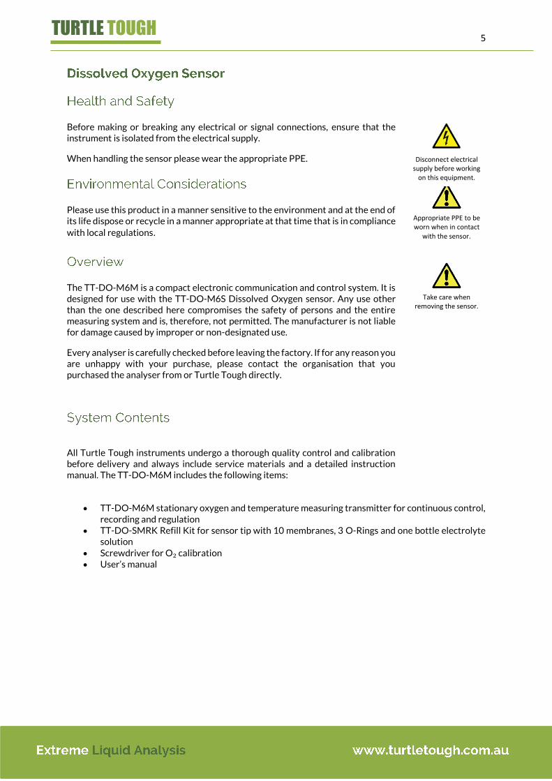
Before making or breaking any electrical or signal connections, ensure that the instrument is isolated from the electrical supply.
When handling the sensor please wear the appropriate PPE.
Please use this product in a manner sensitive to the environment and at the end of its life dispose or recycle in a manner appropriate at that time that is in compliance
with local regulations.
The TT-DO-M6M is a compact electronic communication and control system. It is designed for use with the TT-DO-M6S Dissolved Oxygen sensor. Any use other than the one described here compromises the safety of persons and the entire measuring system and is, therefore, not permitted. The manufacturer is not liable for damage caused by improper or non-designated use.
Every analyser is carefully checked before leaving the factory. If for any reason you are unhappy with your purchase, please contact the organisation that you purchased the analyser from or Turtle Tough directly.
All Turtle Tough instruments undergo a thorough quality control and calibration before delivery and always include service materials and a detailed instruction manual. The TT-DO-M6M includes the following items:
TT-DO-M6M stationary oxygen and temperature measuring transmitter for continuous control,
recording and regulation TT-DO-SMRK Refill Kit for sensor tip with 10 membranes, 3 O-Rings and one bottle electrolyte
solution Screwdriver for O₂ calibration User’s manual
Danger
Disconnect electrical supply before working
on this equipment.
Appropriate PPE to be worn when in contact
with the sensor.
Take care when removing the sensor.

6
TURTLE TOUGH
O₂-Measuring ranges: Three switchable:
0.0 – 5.0 ppm dissolved O2
0.0 – 10.0 ppm dissolved O2
0.0 – 20.0 ppm dissolved O2 O₂-Accuracy: ± 0.5 % of full-scale point °C-Measuring range: 0.0 – 50.0 °C °C-Accuracy: ± 0.1°C, automatic temperature compensation Recorder outputs: 3 switch-selectable outputs for O2, metallically isolated:
0.0 – 5.0 ppm / 4 - 20 mA 1. – 10.0 ppm / 4 - 20 mA 0.0 – 20.0 ppm / 4 - 20 mA (for °C optional: 0.0 – 50.0 °C / 4 - 20 mA)
Power supply: 230/240 V AC, 50/60 Hz, 5 VA Burden: < 800 Ω, short-circuit proof
Fuse: 0.5 A Display: 13 mm high, 3-1/2 digit LCD Sensor: TT-DO-M6S Calibration: Air calibration in the atmosphere Housing: IP 65, PVC housing with transparent door Dimensions: H x W x D: approx. 210 x 200 x 180 mm Weight: Approx. 2.0 kg Option: Recorder output for temperature, various sensor constructions e.g. with
installation pipe

7
TURTLE TOUGH
As with all instrumentation the installation and commissioning of this instrument is crucial to its safe and effective operation. This instrument must only be used for its purpose as outlined in this manual. It must be installed and commissioned in accordance with this manual and by trained, qualified personnel.
Please choose a suitable location for the installation of the electronics. The choice of installation point on any site is a compromise and is best undertaken by an experienced installation engineer. The following is a list of the factors that need to be taken into consideration. This list is not intended as a check-list neither is it implied that the list is complete.
• Ensure that the mounting allows access to all serviceable parts. • Try to mount the electronics in a position where they are not habitually
hosed down in a cleaning process. • The electronics enclosure should be mounted away from sources of heat
or direct sunlight. • Consider the length of wiring runs when mounting the instrument. • Try to keep the electronics away from substations, motors or other large
EMI emitters. • Consider whether the sample will be representative and well mixed. • Consider sample line run times. • Consider sample return points. • In a plastic run, with a low conductivity liquid sample, consider earthing the
sample. • If the instrument is controlling a dosing pump, size the pump appropriately.
Please have a copy of your order with you when you unpack your instrument. All orders are checked when they leave the factory. Please check that you have all the parts that were ordered as soon as you open the box.
If anything is missing, or damaged, please contact your sales outlet immediately. If the instrument needs to be returned for any reason please follow the return instructions given in this manual.
Please dispose of the packing in an environmentally responsible manner and in compliance with local regulations
The TT-DO-M6M electronics enclosure should be mounted away from sources of heat or direct sunlight.
The TT-DO-M6M should be mounted such that the instrument is vertical and that there is sufficient clearance above to allow the enclosure wiring compartment to be opened.
The TT-DO-M6M should be mounted away from sources of vibration and should not be hosed down.
Danger
Electric Shock Hazard
Important
Important
Danger

8
TURTLE TOUGH
Connection has to be carried out only by qualified personnel! Follow the correct main circuit connection. The instrument must NEVER be switched on without an attached sensor.
1 = Ground 2 = Hot (Active) 3 = Zero (Neutral)
4 = - Voltage output 5 = + oC / 1V (option) 6 = + O2 / 1V
7 = - Recorder output temperature 0/4 – 20 mA
(option) 8 = +
9 = - Recorder output oxygen 0/4 – 20 mA
10 = +
11 = Yellow 12 = Green 13 = Black or Grey Probe cable colours 14 = White + Brown 15 = Blue
Set the functional switch to °C. The liquid-crystal display will immediately indicate the temperature value.
If the value shown is not stable, the temperature stabilisation time has probably been too short; it will be necessary to wait until the display has become steady.
Please Note: Since most of the M6M sensor is made of plastic material, the sensor should never be used in water samples with temperatures above 60oC. This would damage the sensor body, the right to claim under warranty would be lost.

9
TURTLE TOUGH
Before carrying out measurements, the sensor must be given sufficient time to adapt to the ambient temperature. This temperature stabilisation is necessary because a change of temperature affects both the conductivity of the electrolyte inside the sensor body and the diffusion capacity of the cathode membrane.
The temperature stabilisation time can be calculated in minutes by allowing a waiting time of three-quarters of a minute for each degree Celsius temperature difference. This results in the following general formula:
Temperature stabilisation time [min] = 3
4 x (maximum ℃ value-minimum ℃ value)
For example, in the case of a temperature difference of 40 °C, which is quite likely with field instruments during summer, the temperature stabilisation time will amount to about 30 minutes.
With sensors that are constantly kept in the measuring liquid, it will not be necessary to observe a temperature stabilisation time.
The best procedure is to wait until the temperature value on the liquid-crystal display remains stable.
In order to obtain reliable measurements, the Turtle Tough sensor must be placed in a position where the natural approach flow amounts to a minimum of 30 cm/s.
If there is no natural approach flow, it will be necessary to create an artificial flow. This can be done as follows:
The first possibility to create an artificial flow is also the simplest: make a stirring movement with the sensor by hand. However, where longer distances are involved, especially when measuring at great depth, the hand-generated approach flow will no longer be adequate since the movement is impeded by the resistance of the liquid. Pull and release the cable continuously during measurement so that the sensor is constantly moving up and down. Note that this method is not suitable for exact measurement results.
Where high-accuracy measurements are required, an absolutely even and reproducible approach flow has to be created artificially. This can only be done with the aid of a flow transmitter, such as our unique and internationally utility-patented TT-O₂-FLOW, a device using an oscillating paddle for creating the necessary approach flow.
Once the proper approach flow has been established, you can proceed with the measurement of the oxygen content. Set the functional switch on O₂. The liquid-crystal display will now indicate the value of the oxygen dissolved in the liquid.

10
TURTLE TOUGH
Every instrument leaves our manufacturing facility in a calibrated condition after going through a test programme of several hours. The user should nevertheless re-check the calibration since a change may have occurred due to long transport or storage periods.
For a fast routine check it is sufficient to have the sensor in atmospheric air. The air calibration table on the front panel of your instrument shows the appropriate oxygen calibration value per degree Celsius.
For example: 20°C equals 9.7 mg/l O₂ or 21°C equals 9.5 mg/l.
If the liquid-crystal display of the instrument indicates, for example a temperature of 20.5°C, the changeover to oxygen should produce the reading 9.6 mg/l O₂. This is the arithmetic mean between the values 20 °C (9.7 mg/l O₂) and 21 °C (9.5 mg/l O₂).
If the value displayed does not correspond to the value on the table or to the calculated value, it will be necessary to recalibrate using the calibration potentiometer by means of the screwdriver included.
If the setting is correct, the device is ready for carrying out measurement.
Calibration in Atmospheric Air The 1-point calibration in atmospheric ambient air is the simplest type of calibration. The front panel of the instrument incorporates the calibration table for air calibration.
1. Put the sensor in a shaded place (avoid direct sunlight). The tip of the sensor and the membrane have to be dry - remove any humidity by dabbing the tip with tissue paper. Cover the sensor i.e. with newspaper to avoid any wind on the tip.
2. Wait for at least 15-20 minutes to be sure that the sensor has reached ambient temperature. 3. After determining the air temperature please read the associated calibration value on the air
calibration table. Switch over to O₂ and calibrate using the calibration potentiometer by means of the screwdriver included.
Please note: For high accuracy calibration of your instrument, barometric pressure should be taken into consideration.
Different air pressures result in different calibration values, so for high accuracy readings a calibration of your instrument taking barometric pressure into consideration must be performed.
If you know the pressure for your location (see table on the left side), you can correct the calibration value according to the following formula:
Corrected calibration value [ppm] = Pressure[mbar] x Table calibration value [ppm]
1013 [mbar]
11
TURTLE TOUGH
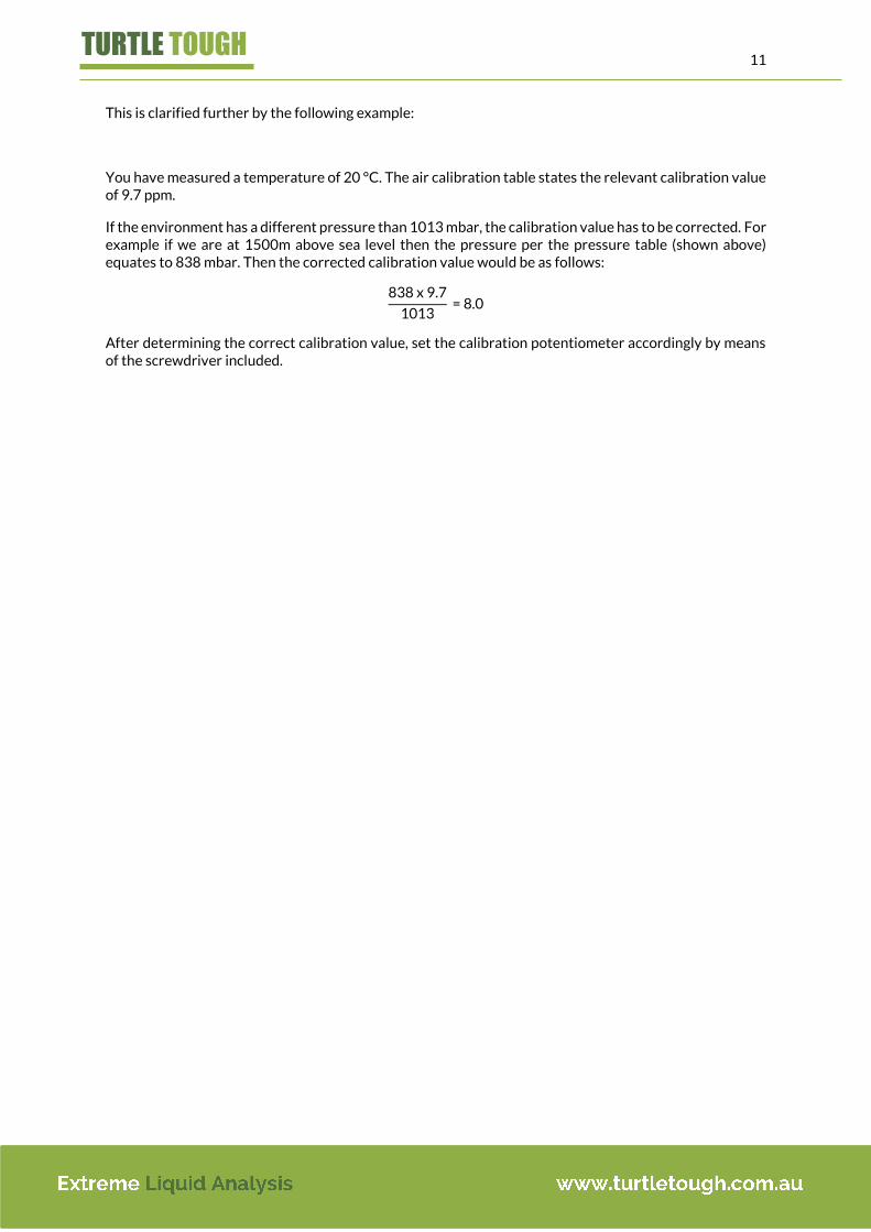
This is clarified further by the following example:
You have measured a temperature of 20 °C. The air calibration table states the relevant calibration value of 9.7 ppm.
If the environment has a different pressure than 1013 mbar, the calibration value has to be corrected. For example if we are at 1500m above sea level then the pressure per the pressure table (shown above) equates to 838 mbar. Then the corrected calibration value would be as follows:
838 x 9.7
1013 = 8.0
After determining the correct calibration value, set the calibration potentiometer accordingly by means of the screwdriver included.

12
TURTLE TOUGH
Turtle Tough TT-DO-M6M Sensors, due to their design and construction, are extremely corrosion, vibration, and knock resistant.
The sensor body (6) and most other sensor components are made of plastic material suitable for recycling. Please Note: The electrolyte fill screw (8) must consist of non-conductive material; it must never be replaced by a metal screw.
The visible cathode (3) consists of fine silver in the case of the “active” sensor and of gold in the case of the “passive” sensor.
The anode, which can only be seen through the automatic pressure compensation (7), consists of lead or, in the case of the “passive” sensor, of silver.
Directly behind the cathode (not visible!), there are two temperature sensors for supporting the display and compensation of the temperature.
The cathode membrane (2) is the most sensitive part of the sensor, although it is made of a strong Teflon material. It is held by means of two red collars (4) and one O-Ring (5). During measurements, the membrane must not come into contact with sharp objects such as stones or sharp-grained sand, which might damage the membrane surface.
The sensor tip is provided with a screw-on protection cap (1). The active sensor elements and the electrolyte tank are dimensioned
to permit application with great long-term stability. The theoretical life amounts to at least 20 years.
We offer our sensors in two different types: the “active” and the “passive” sensors. The outer design of both systems are nearly the same, the selection of the electrode materials and of the electrolyte are different:
Element Active sensor Passive sensor
Cathode Silver Gold
Anode Lead Silver
Electrolyte Liquid Liquid
Material of sensor body PVC PVC
Membrane Teflon Teflon
Pressure compensation Automatic Automatic
Temp. compensation Automatic Automatic
Max operation temp. 50oC 50oC
Calibration Single point air Single point air

13
TURTLE TOUGH
Part Number Description
TT-DO-SMRK Refill Kit for sensor tip with 10 membranes, 3 O-Rings and 1 bottle electrolyte solution
TT-DO-SMK Refill Kit, without electrolyte
TT-DO-ER Electrolyte Solution, 50 ml bottle
TT-DO-ER-500 Electrolyte Solution, 500 ml bottle
TT-DO-SPPK Refill Kit for pressure compensation part of sensor, with 10 membranes and 1 O-Ring
TT-DO-SPPT Special Tool for pressure compensation ring nut
TT-DO-SOR O-Ring for sensor tip, expansion proof
TT-DO-SPR Polythene Collar (red collar) for sensor tip (one set = 2 pcs.)
TT-DO-SFS Electrolyte Fill Screw, Special Plastic
TT-DO-SORPPM
O-Ring for pressure compensation membrane
TT-DO-SMP Membrane Positioner
TT-DO-SSCM Screw Caps (one set = 3 pcs.)

14
TURTLE TOUGH
When a sensor is not being used for a longer period of time, it is recommended to store it in water, where it should be immersed up to the beginning of the cable. This prevents evaporation of the electrolyte and guards against loss of membrane elasticity.
Note: The sensor must never be stored in a so-called zero solution! This would damage the electrode and void the warranty.
If a measuring instrument has been stored over a longer period without being kept in water, or if it is exposed to high temperatures during summer, it is possible for part of the electrolyte to evaporate. This would, to some extent, impair the functioning of the automatic pressure compensation.
The electrolyte level can be verified by holding the sensor horizontally. You should now be able to see an air bubble no larger than 4 mm in the centre of the pressure-compensation membrane.
Should refilling of the electrolyte be required, it is carried out as follows:
1. Unscrew the electrolyte filler screw with a screwdriver. (For a complete exchange, shake out the old electrolyte, taking care not to knock against anything with the sensor.)
2. Hold the sensor slightly at an angle and fill up with new electrolyte. Gently tapping against the sensor body helps to release trapped air bubbles.
3. Slowly screw in the electrolyte filler screw. Use a small cloth or tissue-paper for wiping off any electrolyte spilt during fastening of the screw.
Fastening of the electrolyte filler screw can create high pressure in the sensor body causing the membrane to become stretched. In such a case it would be necessary to replace the membrane.
Attention: The electrolyte filler screw must consist of non-conductive material; it must never be replaced by a metal screw! Please Note: If the electrolyte comes into contact with your skin, rinse the
affected part immediately under running water.

15
TURTLE TOUGH
The cathode membrane has to be replaced immediately in cases where overpressure during refilling of the electrolyte has led to a shift in the position of the membrane, or where the sensor has not been stored in water over a longer period resulting in a loss of membrane elasticity.
The steps for replacing the membrane are as follows:
1. Unscrew protective cap (or paddle holder). 2. Pull off the first red collar. 3. Pull off the O-Ring. 4. Pull off the second red collar; the membrane normally comes off at
the same time. 5. Hold the sensor vertically and check whether electrolyte is visible
in the white electrolyte channels next to the cathode. If this is not the case make “pumping movements” with your thumb on the pressure-compensation membrane until electrolyte appears in all the electrolyte channels. Please Note: Never use a needle or other sharp objects to create flow, since the white wick-like insert would otherwise be damaged! Doing this voids the warranty.
6. Wipe the cathode clean with tissue-paper, but do not polish it because the “scratched” surface helps to form a film of the electrolyte.
7. Put one drop of electrolyte onto the cathode. 8. Put on the membrane and pull slightly downwards at the comers;
there must be no wrinkles formed on the silver surface. You can use a Membrane Positioner for this if available. (See: Using the Membrane Positioner)
9. Replace the red collar (with the smoothed-off edge forward) and push it down until the groove of the O-Ring is again visible (but no further).
10. Fit the O-Ring. 11. Subsequently fit the second red collar (with the smoothed-off edge
forward). 12. Using a sharp knife carefully cut off any projecting membrane
material below the second red collar. 13. Rinse membrane with water. 14. Screw on protective cap (or paddle holder).
After membrane replacement, recheck calibration (see: “Calibration Verification”).

16
TURTLE TOUGH
Refurbishment is recommended every six months and also whenever the membrane has been damaged. The refurbishment procedure involves both electrolyte replacement and membrane replacement. This ensures that no foreign substances can get into the electrolyte in the case of a damaged membrane. The following briefly describes the steps for replacing the electrolyte and the cathode-membrane:
1. Unscrew protective cap or paddle holder. 2. Pull off the first red collar. 3. Pull off the O-Ring. 4. Pull off the second red collar, remove the old membrane. 5. Unscrew the electrolyte filler screw with a screwdriver. 6. Shake out the electrolyte, taking care not to knock against anything with
the sensor. 7. Hold the sensor slightly at an angle and fill up with new electrolyte. Gentle
tapping against the sensor body helps to release trapped air bubbles. 8. Screw in the electrolyte filler screw slowly. Use a small cloth to wipe off
any electrolyte spilt.
Please Note: If the electrolyte comes into contact with your skin, rinse the affected part immediately under running water.
9. Hold the sensor vertically and check whether electrolyte is visible in the white electrolyte channels next to the cathode.
10. If this is not the case make ”pumping movements” with your thumb on the pressure-compensation membrane until electrolyte appears in all the electrolyte channels.
Please Note: Never use a needle or other sharp objects to create flow, since the white wick-like insert would otherwise be damaged! Doing this voids the warranty.
11. Wipe the cathode clean with tissue-paper, but do not polish it because the “scratched” surface helps to form a film of the electrolyte.
12. Put one drop of electrolyte onto the cathode. 13. Put on the membrane and pull slightly downwards at the comers; there
must be no wrinkles formed on the silver surface. You can also use a Membrane Positioner TT-DO-SMP for this, if available (see: Using the Membrane Positioner) or - the easiest way - use our Screw Cap Assembly TT-DO-SSCM.
14. Replace the red collar (with the smoothed-off edge forward) and push it down until the groove of the O-Ring is again visible (but no further!).
15. Fit the O-Ring. 16. Subsequently fit the next red collar (with the smoothed-off edge forward). 17. Using a sharp knife cut off any projecting membrane material below the second red collar. 18. Rinse membrane with water. 19. Screw on protective cap or paddle holder.
Please Note: Wait at least 30 to 45 minutes before carrying out recalibration. For very accurate measurements it would be best to leave the sensor overnight to stabilise and then recalibrate the next day.

17
TURTLE TOUGH
The waiting period is necessary because the Teflon material of the membrane expands slightly during fitting, but will always shrink back to its original size.
This is also indicated by the liquid-crystal display. Immediately after sensor refurbishment the value is relatively high and then falls progressively over time.
Please read the relevant sections of this manual with regard to the special points to be observed when changing the electrolyte or the membrane.
Pressure compensation membranes have to be replaced when the sensor has been stored over a longer period without being kept in water and the membranes have lost their elasticity; or when the membranes have been damaged.
When measuring often at great depths, the pressure compensation membrane should be checked regularly.
The pressure compensation membrane can be changed as the following describes:
1. Unscrew the pressure nut carefully with the special tool TT-DO-SPPT. 2. Remove the pressure washer. 3. Remove the old pressure membrane and the O-Ring. 4. Refill with electrolyte. Please Note: If the electrolyte comes into contact with your skin, rinse the affected part immediately under running water. 5. Install the O-Ring and a new pressure compensation membrane. 6. Refit the pressure washer. 7. Finally put on the pressure nut and screw it on carefully.
Using the Membrane Positioner Use the Membrane Positioner TT-DO-SMP to easily replace the cathode membrane without any wrinkles.
Follow these steps for replacing the membrane using a Turtle Tough Membrane Positioner:
1. Pull off the frame. 2. Put the Positioner on a table. 3. Centre one membrane on the Positioner. 4. Press the frame over the Positioner - the membrane gets pre-
stretched like on a drum. 5. Hold the Turtle Tough sensor vertically, with the tip upwards. 6. Put one drop of electrolyte onto the cathode.
Please Note: If the electrolyte comes into contact with your skin, rinse the affected part immediately under running water.
7. Place the Positioner over the sensor - so that the membrane touches the cathode - and let it hang down by its own weight.

18
TURTLE TOUGH
8. Gently push down and hold the red collar in its position, then remove the Positioner by sliding it down.
9. Push the red collar down until the groove of the O-Ring is visible (but not further!). Continue with replacing the O-Ring and the second red collar as usual (see: Replacement of the cathode membrane or Sensor refurbishment).
You can also use our ready prepared screw caps (TT-DO-SSCM) with pre-stretched membrane. The screw caps are self-adjusting. In order to change the membrane you simply unscrew the old cap and replace it with a new one.
The simplest and most effective way of membrane replacement is to use our ready prepared screw caps (TT-DO-SSCM) with pre-stretched membrane.
The screw caps are self-adjusting. In order to change the membrane you simply manually unscrew the old cap and replace it with a new one.
The screw caps are used as follows:
1. Unscrew the old screw cap. (Only if you use a screw cap for the first time:
Pull off the first red collar, the O-Ring, and the second red collar. Then replace only the O-Ring, and push it down to the beginning of
the winding.) 2. Refill the electrolyte as usual (see: Refilling of electrolyte). 3. Put 5 drops of electrolyte into the screw cap. 4. Now hold the sensor vertically, with the tip downward. Screw on the screw
cap slowly so that the air can escape, but constantly forward.
Never screw back! The screw cap is prepared with a pre-stretched membrane which gets the required form and stretching while screwing on, and therefore can be screwed on only one time. A screw cap once screwed back and then on again loses this correct position!
Wait at least 30 to 45 minutes before carrying out recalibration. For very accurate measurements it would be best to leave the sensor overnight for the purpose of stabilisation and recalibrate the next day.

19
TURTLE TOUGH
Every Turtle Tough product is thoroughly inspected and tested before leaving the factory and prior to shipping. In addition to any statutory rights and remedies you may have, Turtle Tough warrants all of its products against defective workmanship and faulty materials for 12 months from the date of purchase and undertakes, at its option, to repair or replace, free of charge, each product or part thereof on condition that:
The complete product is returned to Turtle Tough or one of its authorised service agents, in person or freight pre-paid by you, and found, on examination, to be suffering from a manufacturing defect;
The product or relevant part has not been subject to misuse, neglect, or been involved in an accident; and
The repairs are not required as a result of normal wear and tear. Damage caused by wear and tear, inadequate maintenance, corrosion, or by the affects of
chemical processes is excluded from this warranty coverage
The above warranty excludes sensors. Turtle tough warrants sensors for six (6) months from the date of purchase, all other conditions apply. Please note that for sensors, cables must NOT be cut or this will void the warranty. The cable contains a unique identifier laminated to the cable end, and if this is removed we have no way of tracing the product. Sensors dying or expiring in the course of use is not covered by the product warranty. Please see sensor warranty below.
Sensors are a consumable item and as such will deteriorate proportionally to the rate of chemical and physical exposure. It is not possible to predict the rate of deterioration for a particular process, nor can we provide a guarantee on sensor life because it is impossible to predict the rate of exposure, contamination and deterioration. Damage caused by wear and tear, inadequate maintenance, corrosion, or by the effects of chemical processes is excluded from this warranty coverage.
Our agents or representatives may provide you with a life expectancy guide based on similar applications; however this in no-way constitutes a warranty of performance and is a general indicator.
The following are not covered by the warranty:
1. Damage to or deterioration of the analyser housing. 2. Any unit that has been altered or on which the serial number has been defaced, modified, or
removed. 3. Damage, deterioration or malfunction resulting from:
Accident, misuse, abuse, or neglect. Failure to follow instructions supplied with the product. Any shipment of the product (claims must be presented to the carrier). Repair or attempted repair by anyone not authorised by Turtle Tough to repair this product. Causes other than product defects, including lack of technical skill, competence or
experience of the user.

20
TURTLE TOUGH
For some applications we will offer a minimum life expectancy guarantee. Consult your local agent or representative for further information. Where a minimum life expectancy is suggested, Turtle Tough will provide a limited performance warranty based on:
Submission of a complete and accurate application questionnaire prior to purchase, approved by a Turtle Tough representative.
The sensor must be installed in accordance with our recommended guidelines. The sensor must be installed on a Turtle Tough Analyser with data logging capabilities The sensor has been regularly cleaned and calibrated in accordance with our recommended
schedule (as evidenced by the data logger). Data logging information is provided by you. Excludes blown pre-amplifiers (preamps). Preamps are electrical devices that are sensitive to
electrostatic discharge. Sensors with preamps are clearly marked and extra care must be taken when handling these sensors as human contact with the electrical connections can discharge static to the preamplifier causing it to blow. This will render the product inoperable. Sensors with preamplifiers undergo additional quality checks prior to shipment to ensure that preamplifiers are 100% operational upon delivery.
For all return goods the following information must be included in the letter accompanying the returned goods:
Model Code and Serial Number Original Purchase Order and Date Length of time in service and description of the process Description of the fault and circumstances of the failure Process/environmental conditions that may be related to the failure of the sensor Statement as to whether warranty or non-warranty service is requested Complete shipping and billing instructions for return of material, plus the name and phone
number of a contact person that can be reached for further information Clean Statement Returned goods that have been in contact with process fluids must be
decontaminated and disinfected prior to shipment. Goods should carry a certificate to this effect, for the health and safety of our employees. Material Safety Data sheets must be included for all components of the process to which the sensor(s) have been exposed.
For technical support please contact our head office 1300 781 701 or visit our website www.turtletough.com.au for information on sensor care, calibration, wiring and installation related issues.