tutorial bc bridge ssd sofiplus 2014
DESCRIPTION
Tutorial Bc Bridge Ssd Sofiplus 2014TRANSCRIPT
7/21/2019 Tutorial Bc Bridge Ssd Sofiplus 2014
http://slidepdf.com/reader/full/tutorial-bc-bridge-ssd-sofiplus-2014 1/27
SOFiSTiK AG 2014
Bridge Design
Balanced Cantilever Bridge
FEA/SSD/SOFiPLUS Version 2014
7/21/2019 Tutorial Bc Bridge Ssd Sofiplus 2014
http://slidepdf.com/reader/full/tutorial-bc-bridge-ssd-sofiplus-2014 2/27
Bridge Design Tutorial
2
This manual is protected by copyright laws. No part of it may be translated, copied or
reproduced, in any form or by any means, without written permission from SOFiSTiK AG.
SOFiSTiK reserves the right to modify or to release new editions of this manual.
The manual and the program have been thoroughly checked for errors. However, SOFiSTiK
does not claim that either one is completely error free. Errors and omissions are corrected as
soon as they are detected.
The user of the program is solely responsible for the applications. We strongly encourage the
user to test the correctness of all calculations at least by random sampling.
7/21/2019 Tutorial Bc Bridge Ssd Sofiplus 2014
http://slidepdf.com/reader/full/tutorial-bc-bridge-ssd-sofiplus-2014 3/27
Bridge Design Tutorial
Content 3
Table of Contents
1 Project Description ......................................................................................................... 4
1.1 Geometry ........................................................................................................................ 4
2 Model: ............................................................................................................................. 5
2.1
SOFiPLUS: ..................................................................................................................... 5
2.2 Cross Section ................................................................................................................. 7
2.3
Load Case Manager ..................................................................................................... 10
2.4 Cross Section - Reinforcement .................................................................................... 11
3
Pre-stressing: ............................................................................................................... 12
3.1
Tendon generation inside SOFiPLUS .......................................................................... 12
3.2 Tendon Generation with “User Task”: .......................................................................... 14
4 Construction Stage Manager: ....................................................................................... 15
4.1 Stages: ......................................................................................................................... 15
4.2
Groups: ......................................................................................................................... 16
4.3 Loads: ........................................................................................................................... 17
4.4 Control Parameters: ..................................................................................................... 17
5 Traffic loads: ................................................................................................................. 19
6
Combinations, design – CSM_DESI: ........................................................................... 24
7
Additional definitions: ................................................................................................... 27

7/21/2019 Tutorial Bc Bridge Ssd Sofiplus 2014
http://slidepdf.com/reader/full/tutorial-bc-bridge-ssd-sofiplus-2014 4/27
Bridge Design Tutorial
Balanced Cantilever Bridge 4
1 Project Descript ion
This tutorial hand out requires basic SOFiSTiK knowledge and is supposed to be used within
a training session run by a SOFiSTiK trainer.
Inside this tutorial we guide you through the following bridge project. The analytical model of
the bridge consists of quadrilateral elements QUAD’s (superstructure) and beam elements
(columns):
For a better understanding and reproducing, we split up the data files according to the differ-
ent chapters. This enables you to start in the middle of the Tutorial if necessary.
The idea of this tutorial is to guide you through a simple RC bridge project and introduce the
general workflow showing the necessary program tools and functions. All steps like model-
ling, loading, traffic, combinations etc. are simplified.
If there are any hints of new tasks that have to be modified manually (new tasksnamed “Text Editor (Teddy)”) you find further information’s directly in those tasks.Please open data files related to the chapter
1.1 Geometry
Bridge Geometry:
Spans [m]: - 10 - 30 - 60 - 30 - 10
Stations [m]: 0 10 40 100 130 140
Bridge Materials:
Concrete bridge deck: C 40/50
Concrete columns: C 40/50
Reinforcement steel: B 500
7/21/2019 Tutorial Bc Bridge Ssd Sofiplus 2014
http://slidepdf.com/reader/full/tutorial-bc-bridge-ssd-sofiplus-2014 5/27
Bridge Design Tutorial
Balanced Cantilever Bridge 5
2 Model:
Start SSD, new project, EN1992-2004, Road Bridges, 3D FEA
Check material (C40/50, B500)
Open SOFiPLUS(-X) to define:
- Cross section(s)
- System axis
- Variables
- Beam elements
- Supports
- Load actions (G_1, G_2, P, C, L, F)
- Loading cases for self weight (test), Settlement
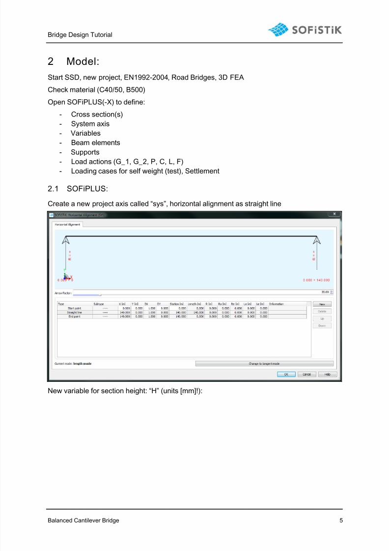
2.1 SOFiPLUS:
Create a new project axis called “sys”, horizontal alignment as straight line
New variable for section height: “H” (units [mm]!):

7/21/2019 Tutorial Bc Bridge Ssd Sofiplus 2014
http://slidepdf.com/reader/full/tutorial-bc-bridge-ssd-sofiplus-2014 6/27
Bridge Design Tutorial
Balanced Cantilever Bridge 6
Placements are so called “points of interest” along axis. Here: we use “supports” and “con-
struction joints”.
Hint: use “station offset” for quicker definitions.
Support axis @: 0, 10, 40, 100, 130, 140
Construction point/joints @: 10 - 40 incr. 3.0m40- 100 incr. 3.0m100- 140 incr. 3.0m
7/21/2019 Tutorial Bc Bridge Ssd Sofiplus 2014
http://slidepdf.com/reader/full/tutorial-bc-bridge-ssd-sofiplus-2014 7/27
Bridge Design Tutorial
Balanced Cantilever Bridge 7
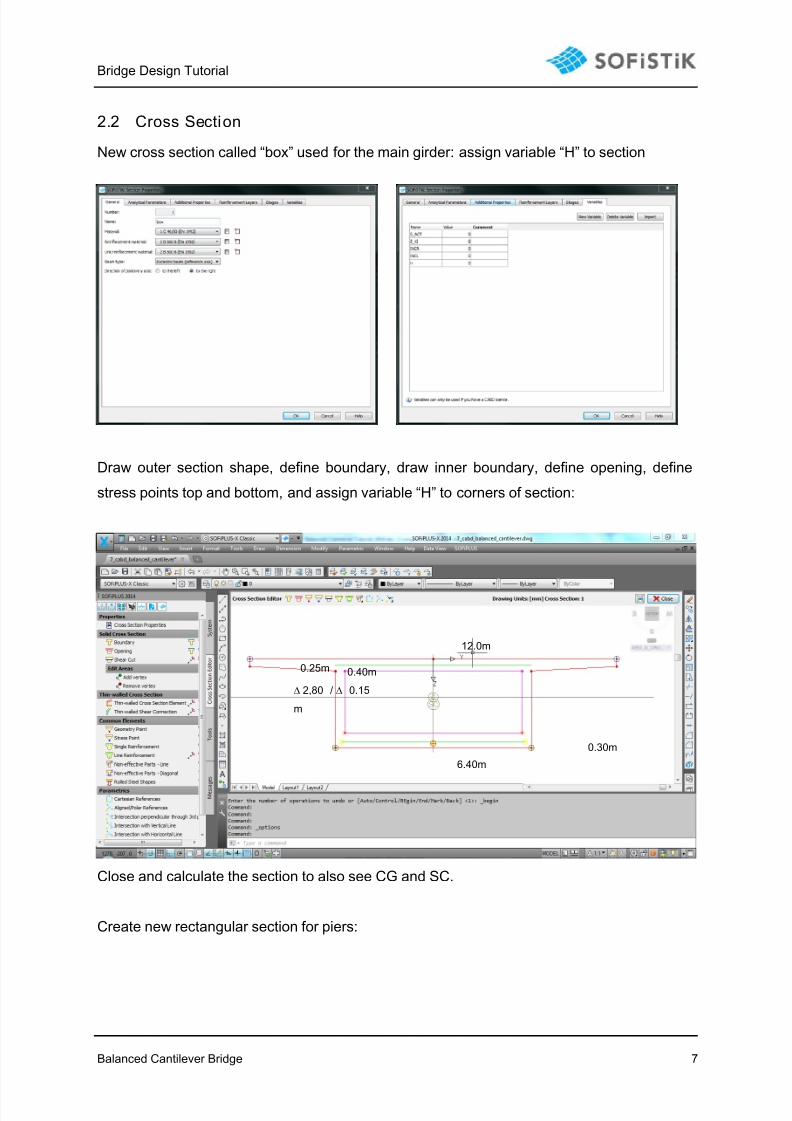
2.2 Cross Section
New cross section called “box” used for the main girder: assign variable “H” to section
Draw outer section shape, define boundary, draw inner boundary, define opening, define
stress points top and bottom, and assign variable “H” to corners of section:
Close and calculate the section to also see CG and SC.
Create new rectangular section for piers:
12.0m
0.25m 0.40m
6.40m
0.30m
2,80 / 0.15
m

7/21/2019 Tutorial Bc Bridge Ssd Sofiplus 2014
http://slidepdf.com/reader/full/tutorial-bc-bridge-ssd-sofiplus-2014 8/27
Bridge Design Tutorial
Balanced Cantilever Bridge 8
Create a new structural line and assign section to axis (segment on bridge axis – see right
mouse click menu):
Define meshing options: “mesh as one element” for balanced cantilever parts, automatic
meshing for columns and side span meshing.
The support placements are displayed as grey rectangle. Double-click on placements for
support axis to work on local section at this specific placement: bearings, columns, eccentric
connections (constraints):

7/21/2019 Tutorial Bc Bridge Ssd Sofiplus 2014
http://slidepdf.com/reader/full/tutorial-bc-bridge-ssd-sofiplus-2014 9/27
Bridge Design Tutorial
Balanced Cantilever Bridge 9
Note: group numbers for beam and spring elements must be defined correctly to match with
construction sequence:
7/21/2019 Tutorial Bc Bridge Ssd Sofiplus 2014
http://slidepdf.com/reader/full/tutorial-bc-bridge-ssd-sofiplus-2014 10/27
Bridge Design Tutorial
Balanced Cantilever Bridge 10
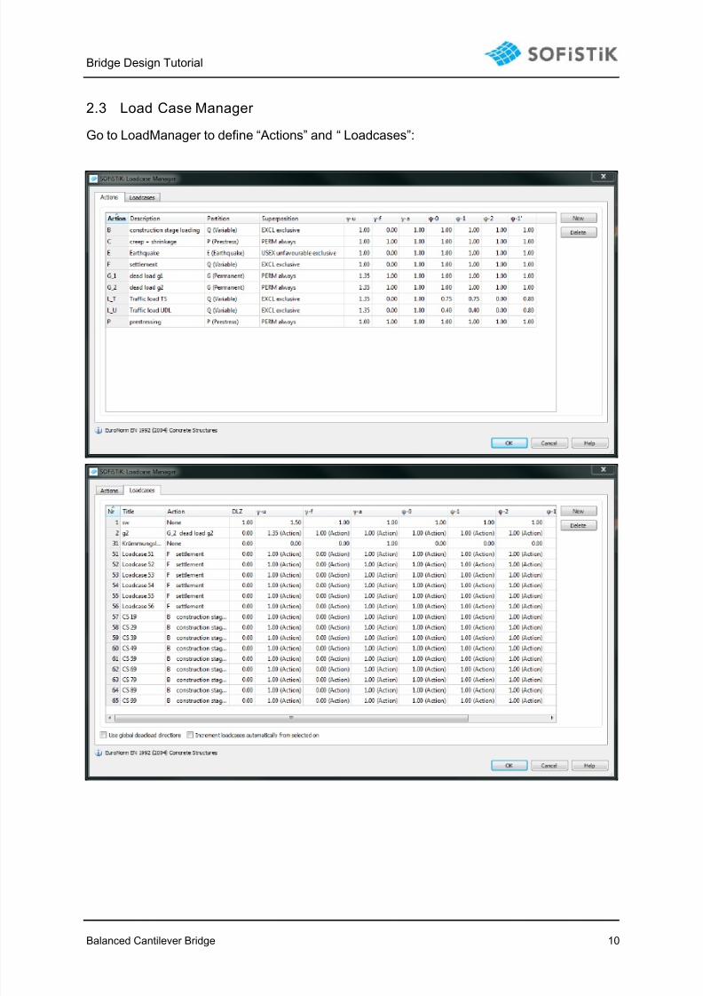
2.3 Load Case Manager
Go to LoadManager to define “Actions” and “ Loadcases”:
7/21/2019 Tutorial Bc Bridge Ssd Sofiplus 2014
http://slidepdf.com/reader/full/tutorial-bc-bridge-ssd-sofiplus-2014 11/27
Bridge Design Tutorial
Balanced Cantilever Bridge 11
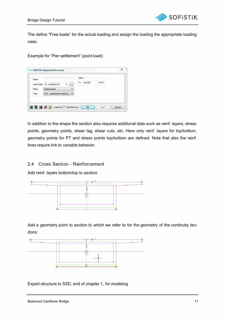
The define “Free loads“ for the actual loading and assign the loading the appropriate loading
case.
Example for “Pier settlement” (point load):
In addition to the shape the section also requires additional data such as reinf. layers, stress
points, geometry points, shear lag, shear cuts, etc. Here only reinf. layers for top/bottom,
geometry points for PT and stress points top/bottom are defined. Note that also the reinf.
lines require link to variable behavior.
2.4 Cross Section - Reinforcement
Add reinf. layers bottom/top to section:
Add a geometry point to section to which we refer to for the geometry of the continuity ten-
dons:
Export structure to SSD, end of chapter 1, for modeling

7/21/2019 Tutorial Bc Bridge Ssd Sofiplus 2014
http://slidepdf.com/reader/full/tutorial-bc-bridge-ssd-sofiplus-2014 12/27
Bridge Design Tutorial
Balanced Cantilever Bridge 12
3 Pre-stressing:
3.1 Tendon generation ins ide SOFiPLUS
Add new material: Y 1770 (EN 1992).
Add a pre-stressing system:
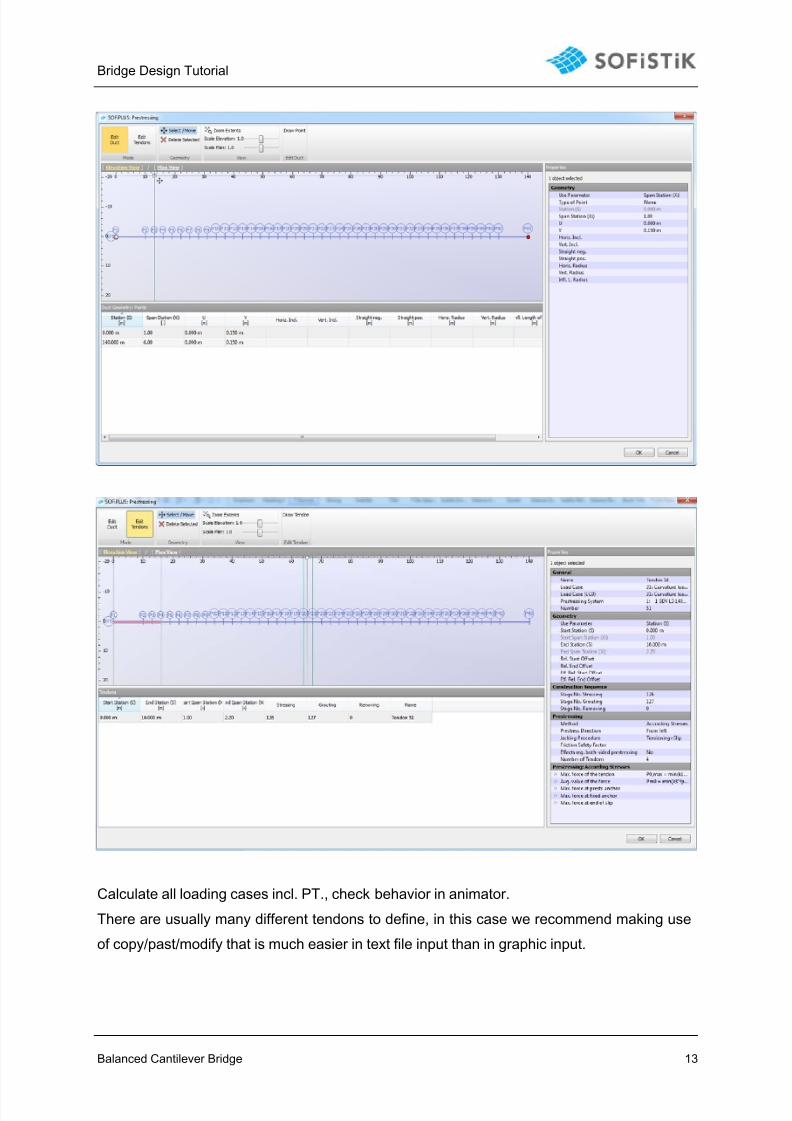
Create Tendons with PT-Editor (developed geometry) with SOFiPLUS:
7/21/2019 Tutorial Bc Bridge Ssd Sofiplus 2014
http://slidepdf.com/reader/full/tutorial-bc-bridge-ssd-sofiplus-2014 13/27
Bridge Design Tutorial
Balanced Cantilever Bridge 13
Calculate all loading cases incl. PT., check behavior in animator.
There are usually many different tendons to define, in this case we recommend making use
of copy/past/modify that is much easier in text file input than in graphic input.

7/21/2019 Tutorial Bc Bridge Ssd Sofiplus 2014
http://slidepdf.com/reader/full/tutorial-bc-bridge-ssd-sofiplus-2014 14/27
Bridge Design Tutorial
Balanced Cantilever Bridge 14
3.2 Tendon Generation with “ User Task” :
With right mouse click on the task we can view input in text format. Next step is to complete
the tendons, done via text input “TEDDY”. See input in text files. We use F1 for help as well
as we use variable definitions for having flexibility for number of tendons, geometry, etc.:
We also introduce a few variables for “number of tendons per stage”, segment lengths, dis-
tances etc. These variables will make it easier to optimize the PT.
There are three TEDDY tasks for PT in the cantilevers, PT for the continuity tendons and for
the side spans. After calculating the tendons, we can view reports, animator, and also the PT
loading cases.
the loadcases for the tendons will not be used for the construction stages. Theseare “storage cases” where the PT loading info is generated and stored for later use.
Note: important input also predetermining the stage definitions in the following chapter are
the ones for
jacking the tendon … in which stage (ICS1)?
grouting the tendon … in which stage (ICS2)?
removing the tendon … in which stage (ICS3)?
7/21/2019 Tutorial Bc Bridge Ssd Sofiplus 2014
http://slidepdf.com/reader/full/tutorial-bc-bridge-ssd-sofiplus-2014 15/27
Bridge Design Tutorial
Balanced Cantilever Bridge 15
4 Construction Stage Manager:
Before going into the stage definitions some things were added to the project:
- A traveler load (Load manager and Loadcases 19, 29, 39,….) for each stage.
- the pt geometry is extended: now we also see a horizontal offset. A new variable is
introduced as well.
Insert new task for CSM, Double click.
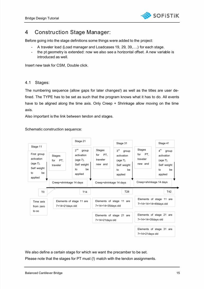
4.1 Stages:
The numbering sequence (allow gaps for later changes!) as well as the titles are user de-
fined. The TYPE has to be set as such that the program knows what it has to do. All events
have to be aligned along the time axis. Only Creep + Shrinkage allow moving on the time
axis.
Also important is the link between tendon and stages.
Schematic construction sequence:
We also define a certain stage for which we want the precamber to be set.Please note that the stages for PT must (!) match with the tendon assignments.
Elements of stage 11 are7+14=21days old
T0
First group
activation
(age 7),
Self weight
to be
applied
Time axisfrom zero
to oo
Stages
for PT,
traveler
Creep+shrinkage 14 days
T14
2nd
group
activation
(age 7),
Self weight
to be
applied
Stages
for PT,
traveler
new and
Creep+shrinkage 14 days
Stage 11
Stage 21
Elements of stage 11 are
7+14+14=35days old
T28
3
rd
groupactivation
(age 7),
Self weight
to be
applied
Stages
for PT,
traveler
new and
Creep+shrinkage 14 days
Stage 31
Elements of stage 21 are
7+14=21days old
Elements of stage 11 are
7+14+14+14=49days old
T42
4
th
groupactivation
(age 7),
Self weight
to be
applied
Stage 41
Elements of stage 21 are
7+14+14=35days old
Elements of stage 31 are
7+14=21days old

7/21/2019 Tutorial Bc Bridge Ssd Sofiplus 2014
http://slidepdf.com/reader/full/tutorial-bc-bridge-ssd-sofiplus-2014 16/27
Bridge Design Tutorial
Balanced Cantilever Bridge 16
4.2 Groups:The group definition as done in SOFiPLUS is now important. The activation of the individual
groups has to be linked to the stage definitions. Also define the age of the next segment
when activated (emod, c+s)
7/21/2019 Tutorial Bc Bridge Ssd Sofiplus 2014
http://slidepdf.com/reader/full/tutorial-bc-bridge-ssd-sofiplus-2014 17/27
Bridge Design Tutorial
Balanced Cantilever Bridge 17
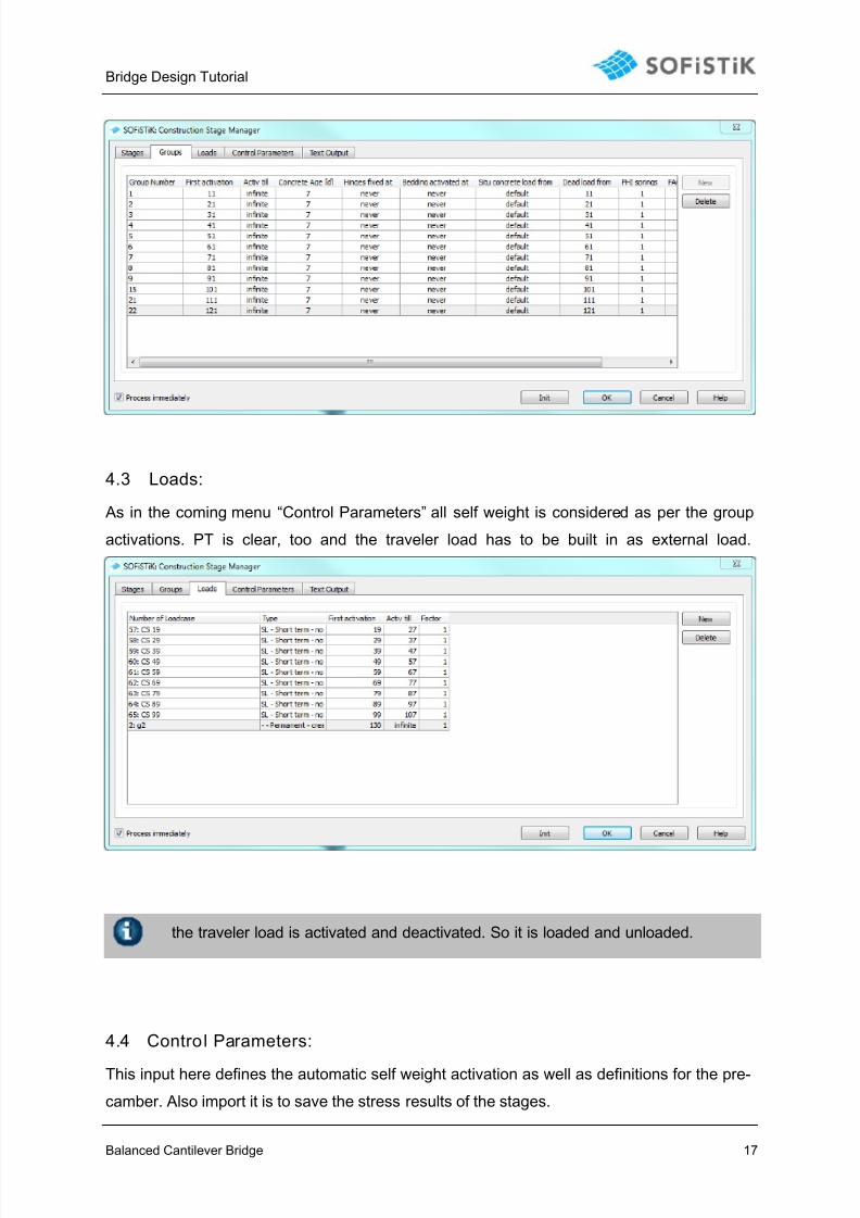
4.3 Loads:
As in the coming menu “Control Parameters” all self weight is considered as per the group
activations. PT is clear, too and the traveler load has to be built in as external load.
the traveler load is activated and deactivated. So it is loaded and unloaded.
4.4 Control Parameters:
This input here defines the automatic self weight activation as well as definitions for the pre-
camber. Also import it is to save the stress results of the stages.

7/21/2019 Tutorial Bc Bridge Ssd Sofiplus 2014
http://slidepdf.com/reader/full/tutorial-bc-bridge-ssd-sofiplus-2014 18/27
Bridge Design Tutorial
Balanced Cantilever Bridge 18
After calculation, please check animator, report with special regard to the Loading Case re-
sults 4 000+, 5 000+, 6 000+. 7 000+.
In case of more than 999 construction stages the automatic generated LC numbersare 40 000+, 50 000+, 60 000+. 70 000
7/21/2019 Tutorial Bc Bridge Ssd Sofiplus 2014
http://slidepdf.com/reader/full/tutorial-bc-bridge-ssd-sofiplus-2014 19/27
Bridge Design Tutorial
Balanced Cantilever Bridge 19
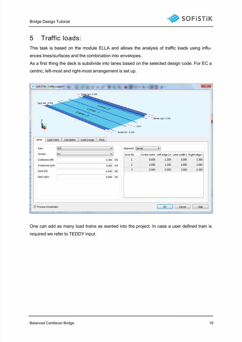
5 Traffic loads:
This task is based on the module ELLA and allows the analysis of traffic loads using influ-
ences lines/surfaces and the combination into envelopes.
As a first thing the deck is subdivide into lanes based on the selected design code. For EC a
centric, left-most and right-most arrangement is set up.
One can add as many load trains as wanted into the project. In case a user defined train is
required we refer to TEDDY input.

7/21/2019 Tutorial Bc Bridge Ssd Sofiplus 2014
http://slidepdf.com/reader/full/tutorial-bc-bridge-ssd-sofiplus-2014 20/27
Bridge Design Tutorial
Balanced Cantilever Bridge 20
As a next step we select the wanted degrees of freedom. As results we get max/minN,
max/min VY etc., each one with co-existing (associated) forces.
These envelope results are stored as “matrix” as in an XLS table (columns and lines):
The column headers are called as the degree of freedom (N, Vy,..), the lines are following a
numbering scheme that is based on a default set which can also be adjusted:
Example:
N Vy Vz Mt My Mz
Line 101 maxN co-existing (associated) forces
Line 102 minN co-existing (associated) forces
Line 103 co-ex. maxVy co-existing (associated) forcesLine 104 co-ex minVy co-existing (associated) forces
Line 105 co-ex co-ex maxVz co-existing (associated) forces
Line 106 co-ex co-ex minVz co-existing (associated) forces
Line 107 co-ex co-ex co-ex maxMt co-ex co-ex
Line 108 co-ex co-ex co-ex minMt co-ex co-ex
Line 109 co-ex co-ex co-ex co-ex maxMy co-ex
Line 110 co-ex co-ex co-ex co-ex minMy co-ex
Line 111 co-ex co-ex co-ex co-ex co-ex maxMz
Line 112 co-ex co-ex co-ex co-ex co-ex minMz
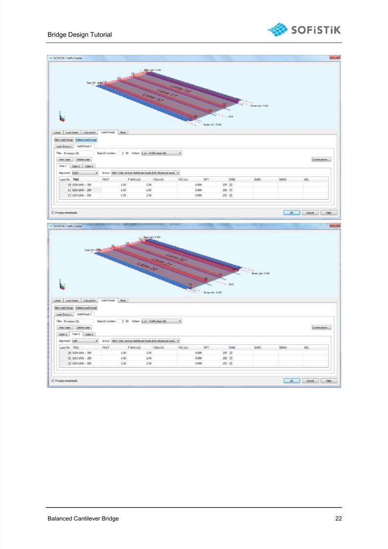
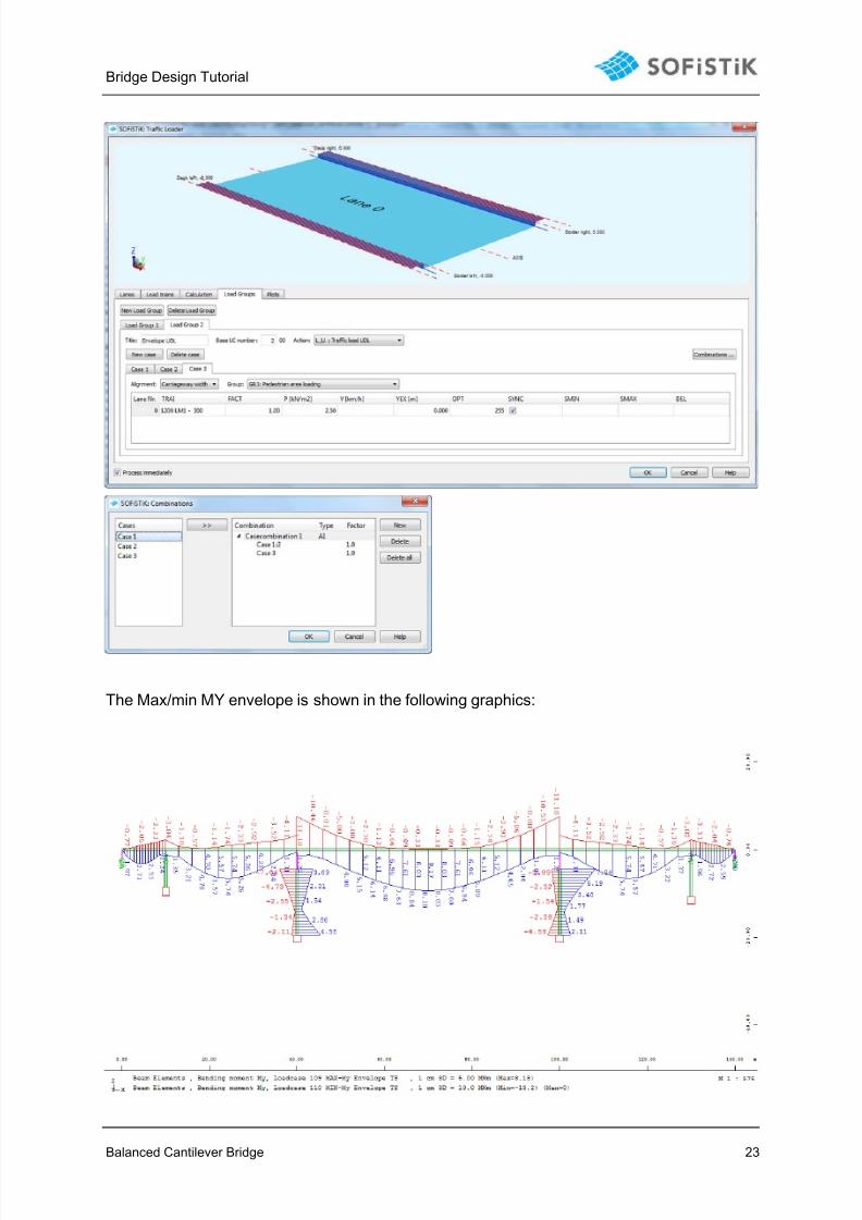
We now assign which load train is moving on which lane and set up so called “cases” each
one representing a certain loading scenario.

7/21/2019 Tutorial Bc Bridge Ssd Sofiplus 2014
http://slidepdf.com/reader/full/tutorial-bc-bridge-ssd-sofiplus-2014 21/27
Bridge Design Tutorial
Balanced Cantilever Bridge 21
Also an “action” type has to be defined so that the program knows the category of the result
envelopes.
7/21/2019 Tutorial Bc Bridge Ssd Sofiplus 2014
http://slidepdf.com/reader/full/tutorial-bc-bridge-ssd-sofiplus-2014 22/27
Bridge Design Tutorial
Balanced Cantilever Bridge 22
7/21/2019 Tutorial Bc Bridge Ssd Sofiplus 2014
http://slidepdf.com/reader/full/tutorial-bc-bridge-ssd-sofiplus-2014 23/27
Bridge Design Tutorial
Balanced Cantilever Bridge 23
The Max/min MY envelope is shown in the following graphics:

7/21/2019 Tutorial Bc Bridge Ssd Sofiplus 2014
http://slidepdf.com/reader/full/tutorial-bc-bridge-ssd-sofiplus-2014 24/27
Bridge Design Tutorial
Balanced Cantilever Bridge 24
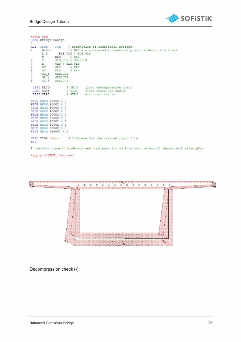
6 Combinations, design – CSM_DESI:
For this part, there is not Graphic User Interface available. The user has the possibility to set
up individual combinations for the relevant ULS and SLS combinations (using module MAX-
IMA) and to do the design manually (using modules AQB for beams and BEMESS for shell
elements).
Based on the result coming from CSM one can also extend the CSM to do the design. The
CSM results are here combined with the final combinations of say temperature, traffic, set-
tlement etc. In addition to the actions to be combined with the stage results one can also
shows elements for detailed stress checks on element level.
Similar to CSM a batch file consisting of input for MAXIMA, AQB and/or BEMESS is generat-
ed and executed.
This generated file called (project)_desi.dat can also be edited and modified.
7/21/2019 Tutorial Bc Bridge Ssd Sofiplus 2014
http://slidepdf.com/reader/full/tutorial-bc-bridge-ssd-sofiplus-2014 25/27
Bridge Design Tutorial
Balanced Cantilever Bridge 25
Decompression check (-):

7/21/2019 Tutorial Bc Bridge Ssd Sofiplus 2014
http://slidepdf.com/reader/full/tutorial-bc-bridge-ssd-sofiplus-2014 26/27
Bridge Design Tutorial
Balanced Cantilever Bridge 26
Decompression check (-):
Does not pass, varying of number of tendons as option to adjust design.
7/21/2019 Tutorial Bc Bridge Ssd Sofiplus 2014
http://slidepdf.com/reader/full/tutorial-bc-bridge-ssd-sofiplus-2014 27/27
Bridge Design Tutorial
7 Additional definitions:
The example is extended by the following details:
- The substructure is also linked to the girder, follows when changing the axis geome-
try.
- Traffic is enhanced in such way that we now have two envelopes for UDL and truck
loads: L_T and L_U. This is part of the “Load groups” definition.
- The combinations are not done using the automated CSM DESI wizard, but manually
using MAXIMA.
- Same for the ULS and SLS design: the necessary input is done manually in AQB in-
stead of using the CSM DESI definitions.
- In this part there is a warning message saying that no torsion reinforcement layer is
found, this can be extended within the cross section if wanted.
Addi tional comments:
The procedures shown here describe the general workflow for a simplified but realreinforced concrete bridge project.Real projects will require a more detailed input for most of the parts specificallywhen doing combinations.This example can be understood as getting started reference for a RC Bridge pro- ject using SOFiSTiK software.
Feedback will be much appreciated. Please send us your comments via Email [email protected] with subject “Reinforced Concrete Bridge Tutorial”.