twinningprocedure withinindustry4 - polito
TRANSCRIPT

Twinning ProcedureWithin Industry 4.0
Digital twin application on safety issue ofhuman-collaborative robot
Student: CHEN Hongyu
S244378
Supervisor: DEMICHELA MICAELA
Abstract
As the global production patterns change gradually into multiple varieties and small batchmode in industry 4.0, automatic production becomes not flexible enough to handle therequirement, therefore the advantages of collaborative robots are becoming increasinglyapparent. The safety issues of the collaborative working environment have then also emergedinto our sight. This thesis takes collaborative robot as the object of study to discuss a way ofimprove industrial safety with digital twin application. The purpose of the digital twin applicationis to achieve the prediction of the working state of the human collaborative robot. The concept ofdigital twin and the characteristics of human robot collaborative environment is studied, and iscompared with other method to specify the target of this thesis. The detailed methodology ofbuilding and applying digital twin is designed. The methodology contains the modeling, thecalculation of kinematic and dynamic states, the method of guarantee real time characteristic,and the logic design of the control. The software CATIA and Matlab is used as computer aid forthe 3D modeling, numerical modeling and calculation. The real time capability is realized bysimplification of the data processing process. The logic of control is designed to let the digitaltwin application smart enough to deal with different situations. Then a case study of DoosanCobots is conducted to verify the methodology. Each step of building the digital twin of thehuman robot collaborative environment is described in detail and the performance of detectingand predicting safety issues is simulated and analyzed to draw the final conclusion.
Key words: Digital twin, real time, collaborative robot, prediction, safety
Content
Abstract................................................................................................................................................2Content................................................................................................................................................31. Introduction.....................................................................................................................................5
1.1 Scope..................................................................................................................................... 51.2 Basic information.................................................................................................................. 5
1.2.1 Digital Twin.................................................................................................................51.2.2 Current application of digital twin.............................................................................71.2.3 Human-Robot collaboration...................................................................................... 81.2.4 Ways of improving industrial safety...........................................................................8
2. Data relative to safety and co-robot in digital twin application...................................................102.1 Data of robot....................................................................................................................... 102.2 Data relative to human....................................................................................................... 11
3. Digital twin model creating...........................................................................................................123.1 Robot modeling in digital twin............................................................................................12
3.1.1 3D modeling............................................................................................................. 123.1.2 Numerical modeling.................................................................................................13
3.2 Human modeling in digital twin..........................................................................................143.2.1 Detecting method.................................................................................................... 153.2.2 Selection of detecting point.....................................................................................163.2.3 Sensor position and function...................................................................................16
4. Standard of the robot control can be used in digital twin............................................................184.1 Existing standard of robot safety........................................................................................ 184.2 Standard could be used.......................................................................................................18
4.2.1 Brief description of the standard.............................................................................194.2.2 The Injury Index matrix............................................................................................19
5. Logic of digital twin control...........................................................................................................226. Digital twin application malfunction solution...............................................................................247. Case study......................................................................................................................................25
7.1 The performance of Doosan Cobots...................................................................................257.2 The existing issues...............................................................................................................267.3 Improvement of the safety strategy by digital twin application........................................ 26
7.3.1 Robot modeling........................................................................................................267.3.2 Operator modeling...................................................................................................337.3.3 Map of control..........................................................................................................357.3.4 Logic of control.........................................................................................................39
8. Analyze of the results....................................................................................................................419. Conclusions....................................................................................................................................42
9.1 The digital twin application in this thesis........................................................................... 429.2 Future work......................................................................................................................... 42
Acknowledgement.............................................................................................................................44Reference...........................................................................................................................................45

Annex 1..............................................................................................................................................46Annex2...............................................................................................................................................50

1. Introduction
1.1 Scope
In this thesis, I have designed a way to approve digital twin application in industrial, mainlyrelative to safety issues of human collaborative robot. Starting with the introduction of somebasic conceptions such as digital twin, collaborative robot, safety issue in industrial productionand so on. The next part will be a detailed explanation of the design of how to achieve the digitaltwin application, following with a case study based on a existing collaborative robot as the thirdpart. Then some parameters of the case study is chosen as output to generate an analysis of theapplication. The conclusion of how this digital twin works on safety insurance and what can beimproved in the future will be written in the last part.
1.2 Basic information
In this chapter, basic information relate to the topic, digital twin in industry 4.0, will beintroduced. Then according to these information, the general train of thoughts will be decided.The information contains the concept and practical usage of digital twin and the understanding ofits structure, the concept of the target of study in this thesis, which is the collaborative robot, andthe comparison between different safety insurance system in industry to better understand theadvantage and necessity of digital twin application.
1.2.1 Digital Twin
With the improvement of information technologies, many conceptions about intelligentmanufacturing have been put forward all over the world. Such as Industrial 4.0 in Germany,Industrial Internet and manufacturing system based on Cyber-Physical Systems(CPS) in USA, andMade in China 2025 and Internet Plus Manufacturing in China. All of these strategies have acommon purpose which is to achieve the interconnection and interoperable feature betweenphysical and information world of manufacturing. And to over come the communication issuebetween the two world, which is the bottle neck, a conception named digital twin is needed.
At present stage, in industrial field, the physical system and the information system isalready connected together in a certain extent. However, the connection is mainly implementedby human operation, which is lack of continuity, instantaneous and foresee-ability. For example,in regard to the production factors of the workspace, nowadays, the data of the equipment,material, supplies, goods in process, and etc are all automatically acquired to realize the onlineentry of the system data. The data of the information system is then synchronized with the datarelated to the production factors. But in the Industrial 4.0, this is not enough. There need to bean interaction, which fuse the information data and physical state of each factor together. This isalso required when it comes to the control of the production process. The use of digitalinstruments has greatly improved the detection accuracy of the workshop. The computer is used

to analyze and optimize the test data, which makes the result more scientific and accurate.Furthermore, the automated actuators improved the control accuracy on the production site.However, there exists a delay between the physical and the information space, in another word,the actual situation of the production process is different from the controlled one. There are notimely handling and response of the system. Although the real-time capability has already beenimproved as the development of IOT, further efforts are still needed to merge physical andinformation space together.
At the outset, digital twin was put forward by United States Department of Defense toensure the maintenance and support of aerospace vehicles. Digital twin is using a digital copy ofthe physical system to perform real-time optimization[1]. This copy should contain all the factorsrelate to the physical one, including processes, people, places, systems and devices that can beused for various purposes[2]. There should be sufficient sensors and detectors to update thephysical data to the virtual model, while the physical component can be also controlled byoperating the virtual data of the digital twin. The interaction between these two is also veryimportant to carry out the real-time control, optimization and even prediction of failure ofproduct and production process.
Digital twin has following characteristics[4].1. It is the integration of various types of data of the physical object, and is a faithful
mapping of it.2. It exists in the entire life cycle of the physical object, co-evolving with it by continually
accumulating relative knowledge and information.3. It has not only the capability to represent the physical object, but also the ability to
optimize the physical part based on the digital model.The shift to industrial with digital twin can be very difficult for traditional industrial
enterprises because it is a conception far from the traditional experience-based design andmanufacturing that have been used for decades. Designers may no longer need to rely on thedevelopment of the actual physical prototype to verify the design idea, neither the complicatedphysical experiment to test and verify the reliability of products. Without doing a small batch trialproduction, the production bottlenecks can be predicted. And don't even need to go to thescene , can designers discern how the customer's products operate.
This way will not only accelerate the product development process, but also improve theeffectiveness and efficiency of development and production. The understanding of the usage ofproducts will become more effective and help customers to avoid losses. Furthermore, it cantransfer feedback of the customer's actual use more accurately to the designer, implementingeffective improvement of the product. Besides, as manufacturer point of view, the cost, timeusage will be substantially reduced since there will be less test, experiment and trial production.The mass production line based on cyber-physical system will be more intelligent so that it canquickly adapt to new production requirements. The safety of operator can be guaranteed in amore flexible way. Last but not least, the routine maintenance can be replaced by failureprediction of the digital image and the digital twin which have the ability to control the physicalobject in a certain way to avoid the predicted accident and dangerous.

1.2.2 Current application of digital twin
Digital twin has already been used in some regions.Such as, typically, the Grieves combines the physical system to the equivalent virtual system
to get a methods of prediction and elimination of complex system failures, which was used in theapplication experiment in NASA related system[5]. The U.S. Air Force Structural Science Centercombines the ultra-high fidelity virtual model of aircraft with the structural deflection andtemperature calculation models together to develop the prediction of aircraft structural lifebased on digital twinning. And the technical advantages of digital twinning is highly admired[6].Siemens has put forward the concept of "digital twin", which is committed to help manufacturersto build the production system model of integrated manufacturing process in the informationspace, and enable the digitization of the whole process in the physical space from product designto manufacturing execution[7]. In response to the complex needs of interaction of product user,Dassault Systemes has established a 3D experience platform based on digital twins by using userfeedback to constantly improve the product design model of the information world, whichoptimizes the product entity of the physical world. The aircraft radar was taken as an example forverification[8].
To create digital twin of a system, it is required the data and the information of each asset,which can be read from the CPPS(Cyber-Physical Production System). The CPPS is a set ofembedded production systems which communicate and interact with each other in acommunication network. The software of the CPPS contains a lot of information about resources,product and process, as well as cycle time, load level of joining points, etc. These information isfundamental to build digital twin and implement a real-time system into the CPPS. Thecomparison of the information between the current CPPS and the digital image will lead tochanges in the production system[9]. Beyond that, the data can be also obtained by multiplesensor. The virtual representation of the physical part is then realized by combining the sensordata and CAD models together. For instance, a digital shop-floor can be rendered in the 3Denvironment exploiting the capabilities provided by Robot Operating System(ROS) Framework.The workload state and geometrical should also be represented. Furthermore, the dynamicupdate of the digital twin based on real time sensor and resource data coming from the actualshop-floor is required[10].
One of the most important and fundamental issue of making a digital twin is to guaranteethe resource of the data and information. The data can be read from the existing robot’s softwareor the PLC device and can be obtained from sensor. There is also data about newly integratedfactors due to additional mission and requirement, as well as the CAD model of the physicalobject. All of these data should be then be continuously updated to create a synthesis of them.The data model should be generic enough so that is can deal with multiple cases and can be usedby multiple components to carry out their mission. The final job is for the planners of the robotor the mass production line to generate a safe and efficient outline through the digital twin tocomplete the production missions.

1.2.3 Human-Robot collaboration
As the global production patterns change gradually into multiple varieties and small batchmode, automatic production becomes not flexible enough to handle the requirement, thereforethe advantages of collaborative robots are becoming increasingly apparent. This is a producinglayout that combines the repetitive performance of robots with the individual skills and ability ofpeople together. People have an excellent capability for solving imprecise exercises, while robotsexhibit precision, power and endurance[12]. Compared to the other production patterns, theproduction using collaborative robot is not as high-yield as automated production, and not asvarious as manual production, but still has considerable performance. Human-machinecollaboration can also bring benefit to efficiency of the production as well as high flexibility. Soeven there is no particularly outstanding aspect, but the overall utility is the highest.
In order to guarantee the safety during Human-Robot collaboration, relevant safetystandards have been established internationally. Like in ISO 10128-1, there are several standardsand steps to reduce the risk of accident. One is the safety-rated stop monitoring. In specific spotsuch as manually assemble station, the robot will stop when human operates get into the stoparea. Another one is the monitoring of speed and distance. At the same time the minimumdistance for robot stopping should be determined considering also the braking length of therobot. Furthermore, the maximum power and force should be limited during the collaboration.The relevant safety features to minimize risk of a Human-Robot Collaboration applicationcontains safe velocity monitoring, safe workspace and safeguarded zones, safe collision detection,safe force monitoring, safe tool detection, and safe switching of states. The velocity monitoringcan combine with the safe workspace so that make a stepwise reduction in velocity of robotdependent on the distance between robot and operator. For example, when the operator is 5meters away, the robot can move at full speed. While the distance is within 1 meter, the robotwill limit the speed to only 20 percent of its maximum.
1.2.4 Ways of improving industrial safety
Nowadays, as the Intelligent Plant has been carried out and improved, most of the massproduction line verges to automation or semi-automation. It is commonly considered that thesafety relative to the intelligent manufacturing already reach a sufficient high level which is also abottleneck so that it is not necessary to further consider the safety issue. However, there are stillmany accidents caused by these smart robots on the production line. In 29th June 2015, atGerman Volkswagen manufacturer, a 21 years old worker was suddenly impacted andcompressed by the robot which he was debugging and died immediately during the accident. InJuly the same year, on one assembly line of vehicle component in America, a robot accidentallyassembled one part on a worker’s head and smashed his head bone leading to his immediatedeath[3]. It is obvious that there should be a more strict safety standard and a more efficient wayto avoid the industrial accident.
One way to improve the safety level is to develop a system, which monitors the speed andseparation between persons and the robot in order to keep the stopping distance of the robotsmall enough to avoid impacts[11]. In this way, the robot can stop when human enters the
dangerous region or when a collision is about to occur. The cost of this system is also very low.However, there comes many disadvantages too. One is the big challenge to stop and then restartthe robot in a small time and distance due to the high speed and load. Another issue is that thissystem cannot tell accurately when to stop the robot or not. Obviously, if the contact area issharp or small, it will be more dangerous to a round and big touching area. And sometimes underthe situation of big area’s contact, the stop of the robot will be no longer necessary. It will causemuch extra time and power to stop and restart the robot. The safety issue will be overestimated.This characteristic is not suitable for a human-robot collaboration system because it is not preciseenough.
Another way is called torque different method. The principle is whenever there is an contactbetween the robot and the human or other objects, the torque required and the torque provideby the motor will be different. If the difference is big enough, the contact can be classified as ancollision. And the motor can be stopped. This method can also stop the robot whenever animpact occurs. The cost is also low since only need to add torque-meter to the system. However,some dangerous will be underestimated. For example, this method cannot avoid the contactbetween human and the sharp tool on the robot, since it works only after the contact reallyhappens. Besides, the speed of the robot should always be limited in order to be stopped in time.
The concept of using digital twin on safety is to simulate the whole process in a virtualenvironment which is of high imitation of the actual one. The damage can be detected and beevaluated according to standard whether it is required a stop or path changing of the robot. Thedetection is more accurate compared with the previous safety system. Meanwhile, the hugeamount of time of stopping and restarting of the robot each time human enters the stop area canbe saved. By creating digital twin, the stop of the process can even be avoided since therecontains all the data and information required to generate another safe working route. Thesolution will be very flexible and can deal with many different cases. However, if there exists lackof information in the digital twin, some danger may become non-detectable. So the safety systemis also required in some special place.
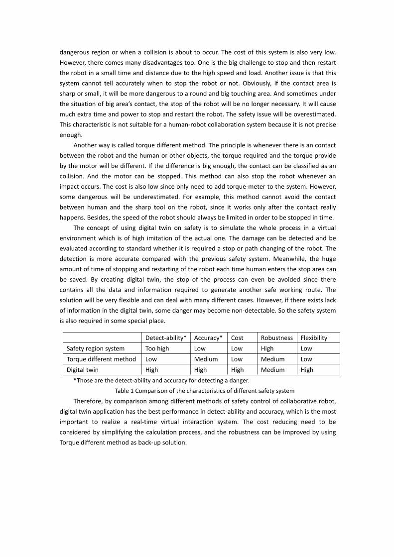
*Those are the detect-ability and accuracy for detecting a danger.Table 1 Comparison of the characteristics of different safety system
Therefore, by comparison among different methods of safety control of collaborative robot,digital twin application has the best performance in detect-ability and accuracy, which is the mostimportant to realize a real-time virtual interaction system. The cost reducing need to beconsidered by simplifying the calculation process, and the robustness can be improved by usingTorque different method as back-up solution.
Detect-ability* Accuracy* Cost Robustness FlexibilitySafety region system Too high Low Low High LowTorque different method Low Medium Low Medium LowDigital twin High High High Medium High

2. Data relative to safety and co-robot indigital twin application
During the production and manufacturing process, the most significant safety problem isrelated to the equipment failure and operation mistakes. Firstly, the temperature of the machinecan’t be too high, especially the overheating of the control system should be strictly avoided. Thelubrication of the moving parts should be maintained, therefore, the temperature again shouldbe acceptable since it will affect the viscosity of the lubricant. Secondly, the operating time,frequency and load should be set reasonable and recorded all the time to predict and avoid thefatigue of the equipment. Furthermore, the most important safety issue is to avoid the directcollision between the robot and human. So that the distance between the robot and the human,the speed should be detected. There should be sensors in different spot of the robot. Not onlybecause the speed difference of various parts, but also due to the difference of shape andmaterial distribution on the robot. For example, if the robot is programmed to stop when theoperator enters into a certain region, the region around the sharp stiff tool should be largercompared with the region near the round deform-able arm. It is obvious that after a collisionwith the same speed and force, a sharp tool will lead to a much bigger damage than a round arm.So a longer braking distance is required.
2.1 Data of robot
There are three kinds of data of a robot arm, geometrical data, kinematic data and dynamicdata.
The geometric data contains the dimension and shape of all parts of the robot, as well as thematerial characteristics. Some data such as the diameter of the robot arm can be neglected innumerical modeling in order to simplify the calculation and guarantee the real-time performanceof the digital twin application.
The kinematic data refers to all the information about the movement of the robot arm. Ineach joint of the robot arm, there is a motor which apply torque to move the arm. The degree offreedom in each joint is normally one, which is the rotation angle of the joint. The angle ofrotation, rotational speed and acceleration of each joint constitute the kinematic data. Bycalculation, the speed and acceleration of all part of the robot can be obtained, which will beused for further calculation.
The dynamic data includes the mass and moment of inertia of the robot, as well we thetorque and power applied by each motor. The dynamic data is meaning used for FEM analysiswhich only works in the background.
These data are all very important as import data to calculate in the digital twin application toavoid safety issues.

2.2 Data relative to human
Compared with the data needed of robot, the data relative to human is quite similar withsome exceptions. The dimension, mass, moment of inertial is also needed. However the humanbody is very complex to model. There will be many approximate treatment of the modelling. Atthe same time, the degree of freedom of human arm joint is much more complex than a robot.One joint such as shoulder can have three degree of freedom: rotation angle around the upperarm, inclination angle and direction of inclination. All those angle, angular speed and angularacceleration are included in the data needed of human modeling. Besides, there are someconstraints of human arm movement. Such as the angle of the elbow between the upper armand the lower arm can be only change in the range of 0 to 180 degrees. Furthermore, there aremany crucial point on human body, of which the position need to be highlighted and mapped onthe virtual body.
Another difference from the robot is that the number of joints is low. In other words, eventhough the degree of freedom of each human body joints in much more complex to model themovement, the whole arm position and movement state is more easy to be caught than therobot arm. For example, if one fix the upper arm and lower arm direction, the position of theelbow is fixed. The same thing can not be done in the robot arm, since there are several jointsbetween two arms. So compared with robot data, which is always same data in each joints, thedata concerned in human body is all data at certain joints.

3. Digital twin model creating
The model of the whole working space should be built according to the structure of digitaltwin application. The model should contains not only the robot, but also the relevant part of thehuman, as well as the connecting part between them. The workbench and the floor can link thehuman model and robot model into a same reference system. The material and the mass shouldbe assigned to each component to help decide the collision criteria. The program that controlsthe actual robot can be also used to control the digital robot. This is convenient because somespeed and force data of certain part can be directly read from the control system. Such as thespeed and route of the mechanical cutters and the maximum torque of the robot motor. However,these data are far from sufficient for a comprehensive monitoring. It is required to get the speedinformation of every part of the robot arm, as well as the exact force or pressure of the collisionarea if it is necessary. This can be achieved by making a simplified numerical modeling of therobot and the human body in the same reference system.
3.1 Robot modeling in digital twin
3D modeling and numerical modeling are both built and used for different purpose. The 3Dmodeling is built in CATIA and numerical modeling is directly calculated in Matlab. The actualcalculation process and modeling process will be done in the part case study.
3.1.1 3D modeling
Figure 1 3D modeling of the robot
The 3D modeling of the robot is build for FEM analysis when necessary. According to theuseful information includes the number of degrees of freedom, the range of each jointmovement, the maximum reach of the robot, the material and the maximum speed of the robot,which can be read from the manual of the robot, an approximate 3D model can be built. Theworkbench should also be considered, only with a simple display which indicates the position ofthe robot. The 3D modeling will then be used to FEM analysis in the background to update thedata of the control system. Therefore, the 3D modeling and the finite element setting can be asdetailed as possible.
3.1.2 Numerical modeling
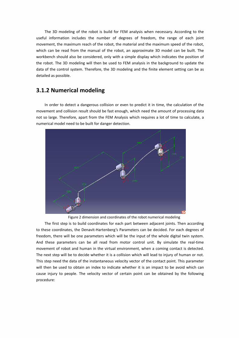
In order to detect a dangerous collision or even to predict it in time, the calculation of themovement and collision result should be fast enough, which need the amount of processing datanot so large. Therefore, apart from the FEM Analysis which requires a lot of time to calculate, anumerical model need to be built for danger detection.
Figure 2 dimension and coordinates of the robot numerical modeling
The first step is to build coordinates for each part between adjacent joints. Then accordingto these coordinates, the Denavit-Hartenberg’s Parameters can be decided. For each degrees offreedom, there will be one parameters which will be the input of the whole digital twin system.And these parameters can be all read from motor control unit. By simulate the real-timemovement of robot and human in the virtual environment, when a coming contact is detected.The next step will be to decide whether it is a collision which will lead to injury of human or not.This step need the data of the instantaneous velocity vector of the contact point. This parameterwill then be used to obtain an index to indicate whether it is an impact to be avoid which cancause injury to people. The velocity vector of certain point can be obtained by the followingprocedure:

Figure 3 parameters required to calculate the velocity vector
The angular speed of one joint can be calculated by the prior one using formula:
iiii kq )1(1i
In which the qi is the speed of degree of freedom of joint i, δ i is the joint i parameter,which is 0 when the joint is revolution and is 1 when the joint is prismatic, ki is the unit vector ofaxis zi.
The velocity of joint i origin of its coordinates relative to the reference frame attached toitself can be calculated by:
iiiiiiii kqpp )(vv 11-1-
In which the pi is the position vector of the origin Oi of the reference frame i with respect tothe fixed global frame which is frame 0.
Then for calculating any random point on each arm of robot, the velocity can be obtained byusing:
iiiRi sv v
In which the si is the position vector of the random point Ri embedded in the link i withrespect to frame i.
Other parameters such as angular acceleration, force and torque of the robot can be alsocalculated using this modeling methods. According to different type of robot, some parameterswill become relevant some will not. For example, for normally controlled robot arm, theacceleration is not necessary, since the speed state can be calculated or ready directly by thecontrolling system of the robot. However, if some machine has function of free movement suchas hammer hitting, the acceleration will be come necessary of the prediction of the impact andthe post analysis.
3.2 Human modeling in digital twin
To realize a comprehensive simulation of the working statues, the workers should also beproperly modeled. The digital mirror of the human body can be called the virtual body. It shouldcontain several functions. The virtual body theoretically should be exactly the same as thephysical body. However, as long as human body is extremely complex and many details are

irrelevant to the operations, and with a more complex virtual body, the arithmetic will also bemore complected to generate more power and cost. So in the point view of efficiency andeconomy, a minimum modeling including the head, main body part and body joints is necessary.And the virtual body should be able to do a real-time movement tracking and imitation of thehuman body. Furthermore, the virtual body can interact with the virtual environment and getinformation about the working and safety statues and show them to our people. In order tosatisfy these conditions, the virtual body should be build with enough elements and degree offreedom to guarantee the implement of different movement of human. And the movementtracking should be accurate enough, since very little tolerance can cause serious danger. Therobot may aim at the workers hand instead of the mechanical part.
Human modeling also contains 3D modeling and the numerical modeling. A significant partof the difficulty is to effectively get the movement data of human body in a very short time ofdelay. To summarize, there are three factors which need to be considered of the human modeling.One is to as precisely as possible map the human movement on the digital human model, whichneed many equipment including position sensor and angle sensor in every joint of human body.The second one is to guarantee the real-time characteristic by either using server with highcalculation speed or reducing the calculation amount of data by some simplification. Another oneis in the view of the human. It is not possible for a man to do the work with full of sensors on thebody, the number of sensors need to be reduced to as less as possible.
3.2.1 Detecting method
Generally, there are quiet large amount of ways to get human body data of virtualmodelling.
In order to distinguish human body among surrounding items, a thermopile array sensor isconsidered. However, it is obvious that there will be much disturbance since most part of therobot will also generate thermal heat. And the heat radiation from surface of human body willlead to a lower accuracy of the detection.
Another way is to use RGB and depth image cameras to get 3D information of human body.There are many drawbacks as well, such as, the color of the environment is limited to avoiddisturbance and the light change will also affect the information acquirement. So in the complexworking environment of the factory, this methods is also not suitable.
The technology of action recognition is also considered, which is more accurate andefficiency. But at the same time, this method costs too much and is not mature enough to use asa way only to get input information. The most resources of the calculation capacity should be puton the analysis of the movement of the human and robot model and to decide whether to avoidthe collision by stopping the robot or other measures.
Therefore, compared to the above methods, instead of using a camera or a sensor from adistance to detect the human movement by observing, a more reliable way is to using somesensors fixed to key points of human body. The sensors can be gravity sensors, gyroscopes,magnetic sensors, and so on. The change of the environment in light and temperature will noteasily affect the using of the sensors, and the data is easy to process so that the burden on thesystem would be less.

Figure 4 ways of detecting human body
3.2.2 Selection of detecting point
Figure 5 possible detecting point on human body
The detecting point should be selected according to human body joints. There are at least 9places that has DOF(as shown in the figure) which need to be detected by sensor, neglecting thedetection of finger movement of each hand. The feature of hand movement is that hand hassmall covered space but large number of DOF, so instead of add numbers of sensor to detecteach knuckle movement, it is more convenient and easy operated to make the hand as a wholeand modeled it according to its covered space. It is same for neglecting the movement of the jaw,change of relative position between torso center and shoulders and so on. The principle ofchoosing the detecting point is that each point corresponds to one rigid part of human body. Forexample, one can twist his waist but the upper body can be considered as a rigid part, so therecan be only one detecting point to detect the movement of the waist.
3.2.3 Sensor position and function
The sensor position can be selected considering two factors. The first one is that the positionis easy to be installed with sensor and the operation of the operator will not be affected a lot. Forexample, since normally a helmet will be required in a factory, one sensor position can be set onthe head. The second factor is to reduce as much as possible the number of the sensors. If therealready installed sensors on the head and the upper body, the rotational angle and inclinationangle of the neck can be calculated since there is only one way to connect those two part ofhuman body. At the same time, if there are already sensors on the upper body and the neck, thehead position and rotational angle can also be calculated.
After considering the two factors mentioned above, among the 9 detecting point mentionedin 3.2.2, five of them can be calculated by data coming from adjacent points. So there are at least4 points need to be detected for the whole human motion mapping in the upper part of the body.For each points, there can be three kinds of degree of freedom to be detected, which are position,

rotation and inclination. So the sensors required includes:Head: position and rotation angle sensorBody: position and rotation angle and inclination angle sensorArm: on the wrist, detecting the position and the inclination anglePosition of elbow, neck, head and shoulder can be calculated by the rotation and inclination
angle of each part based on the position of body and wrist.The detailed modeling procedure will be discussed in the case study.

4. Standard of the robot control can be used
in digital twin
To evaluate whether the human robot collaboration is safe or not, there should be astandard to refer on. There needs to be certification before putting robot into industrial usage.Standards play an important part in this process, to find out what constitutes best practice in safesystem behavior, and in design methodology[13].
4.1 Existing standard of robot safety
ISO 10218—the principal safety requirements standard for robots in industrial environmentsto work autonomously or in collaboration with humans.
The requirements of human robot collaboration in the standard contains five points.• Stopping functions (10218-1)—requirements are specified for how and when the robot
should perform protective or emergency stops when humans are in the robot’s workspace.• Speed and position control (10218-1)—requirements are specified for the maximum
allowable speeds of robot arms and end effector when humans are in the robot’s workspace.• Power and force control (10218-1)—requirements are specified for the maximum
allowable power and forces applied by robot arms and end effector when humans are in therobot’s workspace.
• Design of collaborative operation workspace (10218-2)—requirements are specified forthe layout design of workspace around the robot, including safeguarded spaces (where humansare separated from the robot and protected by safeguards) and collaborative spaces wherehumans are not separated from the robot and hence the robot shall apply the control limitsmentioned above.
• Collaborative operation modes (10218-2)—requirements are specified for the specificoperating modes that must be designed into the robot’s control function when collaborating witha human in the collaborative workspace, including teaching modes and autonomous modes.
These standard can be too restrictive for digital twin application of collaborative robot if putthem directly as the index in the controlling program, since the digital twin has a certaincapability of prediction. In this thesis, only collaborative spaces are considered, the control limitin the digital twin will be recalculated or using other replaceable criterion in order to satisfy thestandard.
4.2 Standard could be used
The injury criteria of automobile crush test can be used, such as: Head Injury criterion(HIC),Neck Injury Criterion(NIC) and so on. These two criterion all need the data of the result of thecollision which is very difficult to be calculated in a short delay.
Once the position of contact is detected, the resultant acceleration and speed of the part of

human head and spine can be calculated using FEM and then obtain the parameter Injury Index.Then this calculated Injury Index need to be compared with the pre-saved Injury Index Limit.Human body models such as THUMS can reliably be used to robustly predict injuries sustained inreal world crashes. The THUMS injury predictions are precise, but it still need time to do thesimulation. Therefore a larger DOE variation study is necessary to more fully quantify correlationsbetween the parameters and the injury predictors. Future work could simulate a wide range ofimpacts to further understand collision parameter effects, robot arm position, speed direction oninjury metrics, organ strain metrics, rib fractures, and the effectiveness of injury mitigationsystems[14]. Then the simulation results can all be put into a map of injury index matrix andsaved in the control unit of the digital twin application.
4.2.1 Brief description of the standard
The Head Injury Criterion(HIC) is shown as below:
5.2
2
112
12 )(1maxHICt
tdtta
tttt
In which:a is the resultant head accelerationt2-t1 is less than 36mst2, t1 is selected so as to maximize HIC.
The HIC limit is set choosing different time interval for different dummy sizes. For example,for a 15 ms interval, the HIC limit is 700 for a large sized male and is 390 for a 1 year old infant. Sofor large sized male, a much more severe impact can be allowed to occur without causing deathor serious injury.
The Neck Injury Criterion(NIC) is shown as below:
22.0NIC relrel vxa
where arel and vrel are the relative horizontal acceleration and velocity between the bottom(T1) and top (C1) of the cervical spine. The constant 0.2 represents the length of the pig neck inmeters and was assumed to be also representative of humans. The limit of NIC is set also byexperiment with dummy or human volunteers[16].
There are also other injury matrix to determine whether a injury will happen during impactsuch as Thoracic Trauma Index (TTI), which is calculated from the vertebral body acceleration,and so on.
4.2.2 The Injury Index matrix
The HIC, NIC and TTI are all related to the car impact test, for which the requirement is tokeep the passenger or the driver from bad injury or death. Meanwhile, what need for the digitaltwin application is to avoid any injury including high level of pain which will affect the operator’sworking condition. Therefore, these criterion is not strict enough. To solve this problem, one wayis to set the limit of these criterion to a more strict value, another way is to use pain study as the

basement to make the best standard for injury and pain avoid.According to reference[15], the pain of different area of human body is related to the strain
of the skin, which is also related to some parameters such as impact force, tensile stress, impactenergy and so on. These parameters can be tested as an index to build the standard for safetycontrol. The relationship between the pain level and the parameters can be only defined byexperiment. For example, with the same impact energy equal to 1.3 J/cm2, the pain level will betotally different when this impact is happened on the side of the lower arm or on the back of thelower arm, as shown in the figure 6.
Figure 6 pain sensitivity on different part of human body
So the parameter IED need to be further related to the pain level at different area of thehuman body. The final standard will be set according to this pain level. The pointer and thematrix in between from the dynamic and kinematic information to the final pain level will be thekey point for this application.
According to the type of the collaborative robot, the input data is better to be the one thatcan be directly measured or detected, such as the position on the robot and on the human body,the degree of freedom of the movement, the speed of the moving part and so on. The purpose isto simplify the calculation process of digital twin during daily usage of the collaborative robot.
The input data should includes position on robot, relative speed between human and therobot, position on human body, the torque of robot and so on.
The output data should be the pain level.The relationship between the input information and the output data is very complex, and
contains numerous of different cases, so they can only be decided by simulations or byexperiments. Several tests can be designed to get the map. For each map, the independentvariable is the relative velocity and the force/torque on the direction of the relative velocity. Andthe dependent value would be the Impact energy density, which is related to the pain of human.
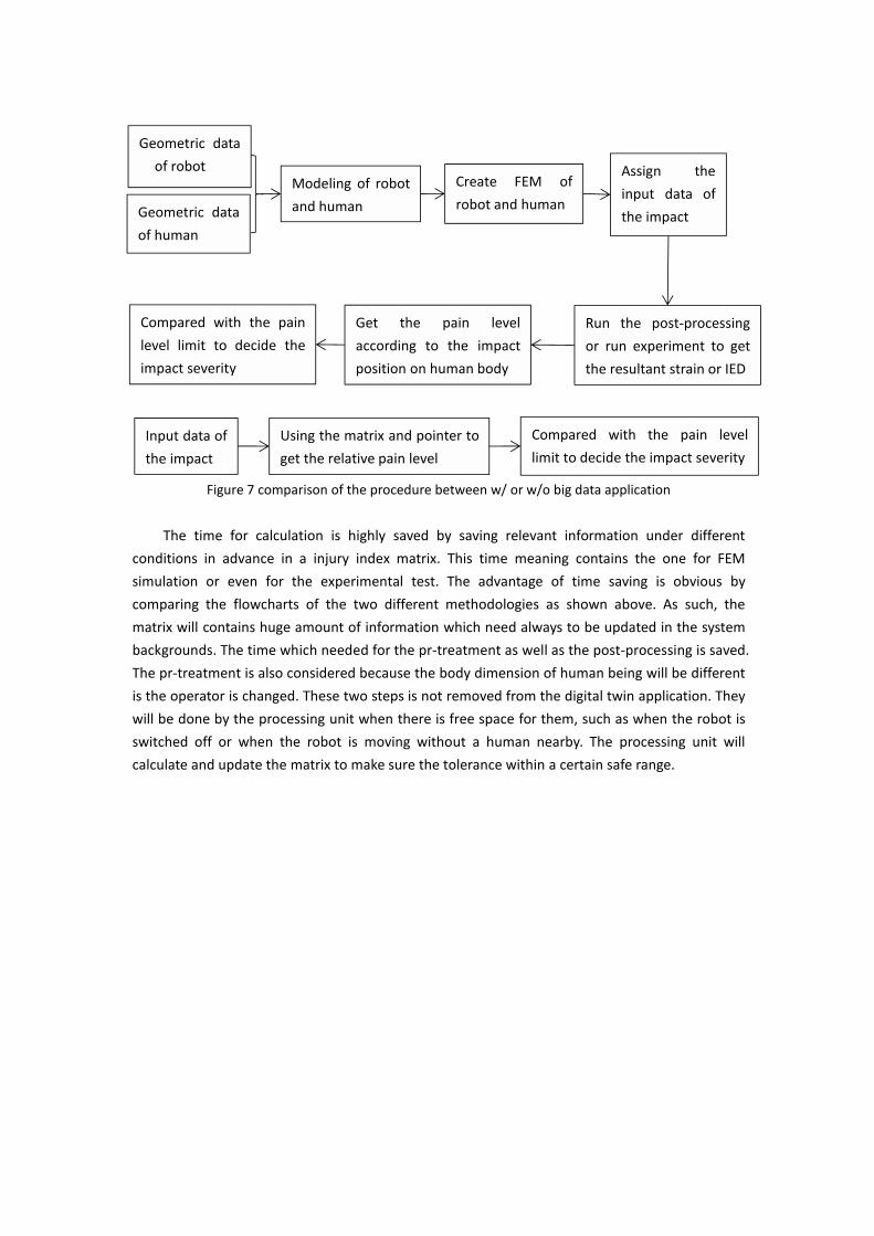
Figure 7 comparison of the procedure between w/ or w/o big data application
The time for calculation is highly saved by saving relevant information under differentconditions in advance in a injury index matrix. This time meaning contains the one for FEMsimulation or even for the experimental test. The advantage of time saving is obvious bycomparing the flowcharts of the two different methodologies as shown above. As such, thematrix will contains huge amount of information which need always to be updated in the systembackgrounds. The time which needed for the pr-treatment as well as the post-processing is saved.The pr-treatment is also considered because the body dimension of human being will be differentis the operator is changed. These two steps is not removed from the digital twin application. Theywill be done by the processing unit when there is free space for them, such as when the robot isswitched off or when the robot is moving without a human nearby. The processing unit willcalculate and update the matrix to make sure the tolerance within a certain safe range.
Modeling of robotand human
Create FEM ofrobot and human
Assign theinput data ofthe impact
Run the post-processingor run experiment to getthe resultant strain or IED
Geometric dataof robot
Geometric dataof human
Compared with the pain levellimit to decide the impact severity
Input data ofthe impact
Using the matrix and pointer toget the relative pain level
Get the pain levelaccording to the impactposition on human body
Compared with the painlevel limit to decide theimpact severity

5. Logic of digital twin control
The logic should consider the collision and the human guidance at the same time, whichmeans the robot can stop whenever a impact which will cause danger to human occurs,meanwhile, it can also allow the force given by human in order to follow the guidance or allowpushing of button on it. This logic will start whenever a contact between human and robot isdetected or predicted. In order to realize a certain predictability, the simulation need to be ran alittle further in the time domain. This time ahead should satisfy two requirements. It should belong enough so that larger than the time for the system to calculate the result plus the time forthe system to react. This also relate to the maximum speed, mass and nominal power of therobot. On the contrary, it should also be short enough, since the human movement after fewseconds can’t be predicted at all.
The next step is to derate the motor of the robot. Not only if it is a dangerous collision, butalso for a normal guidance action of human, the derating of the motor is necessary. In this case, adangerous collision becomes not dangerous after the motor derating, it will be seen as aguidance performance of human and the system will keep the Power and Torque low until thecontact end, then runs in normal state again. The matrix of injury index is used here to determinethe performance and state of each critical point of human body. Then according to the standardrelative to human safety, the collision is dangerous or not will be clear.
Following the logic mentioned above, the system will be able to tell when it is a dangerouscollision and when it is only a soft contact. But it can’t tell the difference between it is the humanguidance on purpose or an accidentally touch. Therefore, by using this logic, the robot will derateitself every time there is a contact. In order to separate the accidental touch from the humanguidance, a further step is added. There should be a certain area on the robot which isspecifically used for human guidance. When the contact detected by the system is apart from thisarea, a comparison without motor derating will be made, and if it is not dangerous, the deratingwill not be proceeded and the system is kept in normal working mode. This added logic can savetime for some unnecessary derating and re-cranking of the motor.
The logical diagram below in figure 8 is a draft layout of what is mentioned above. Duringapplication, more parameters such as the robot type, the calculation capability of the processingunit and so on should be considered. For example, if the robot arm has area on it that is used foroperators to press button to apply certain controlling command, this area should be speciallyconsidered during the design of the logic diagram.
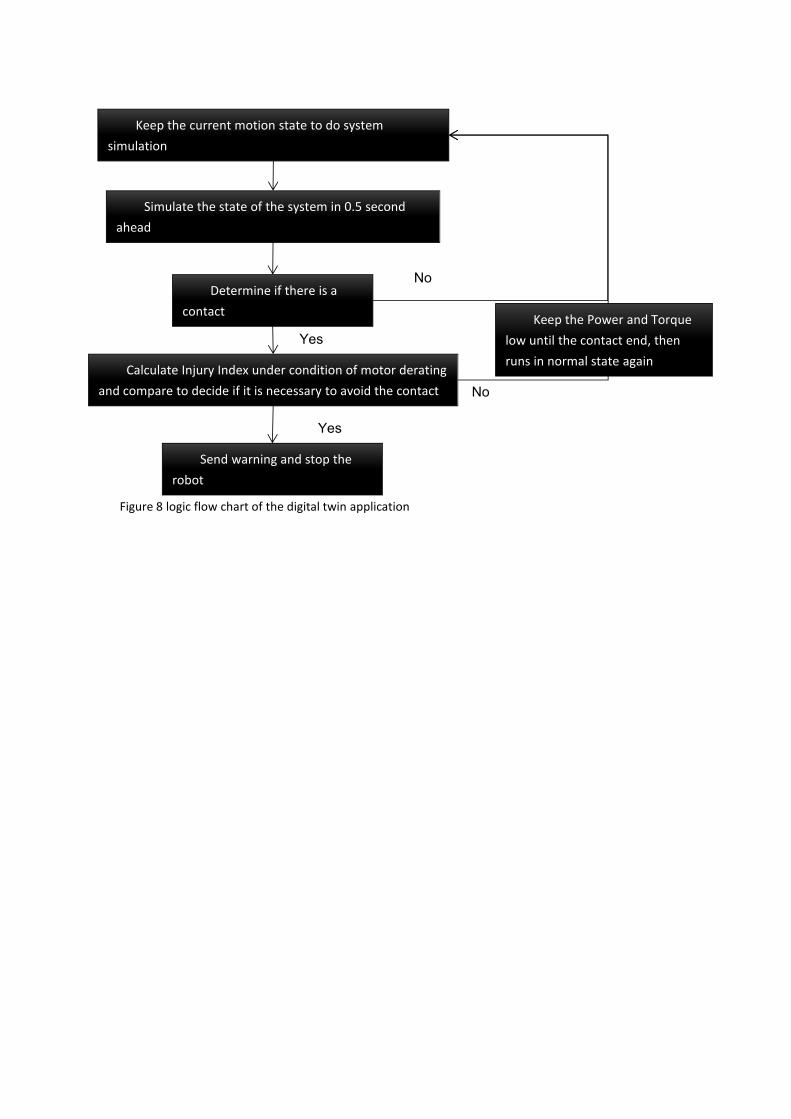
Figure 8 logic flow chart of the digital twin application
Keep the current motion state to do systemsimulation
Simulate the state of the system in 0.5 secondahead
Determine if there is acontact
Calculate Injury Index under condition of motor deratingand compare to decide if it is necessary to avoid the contact
Send warning and stop therobot
Yes
Yes
No
No
Keep the Power and Torquelow until the contact end, thenruns in normal state again

6. Digital twin application malfunction
solution
As the number of sensor has been highly reduced, the margin of error is very low. In thiscase, if some failure happens, the whole system could be not able to work normally, and thesafety can’t be guaranteed anymore.
There are two kinds of possible malfunctions.The first one is the sensor failure. Since the sensor number is already reduced. The
information coming from the failed sensor cannot be replaced by equivalent information fromother sensors. So other safety guarantee method such as the Torque different method used as aback up safety system is necessary. There are two ways of detecting a sensor failure in the system.As the sensor layout has no redundancy, if one sensor is failed with no data output from it, thedigital twin modeling can’t be built, and will be qualified as an failure. For the sensor failurewhich have output data but have high tolerance. This Torque different method can be used onthe contrary as the detector for the sensor failure. Because the sensor failure can cause theresultant acceleration and torque of the collision simulation much different with the actual one.
The second one is the strategy failure. Such as after long time of usage, the map need to beupdated, otherwise there will be high tolerance when calculating Injury Index. To avoid this, theFEM analysis should always be used to simulate and update the map in the backgrounds.However, this will take a large amount of the processing unit and increase the cost a lot,sometimes may even affect the calculation of the numerical system which is not good. In theelectric control mode of the control unit, one new mode named updating can be added. Thesystem can get into this mode once one input data is modified and after the first switch off of therobot after that. The system will then start to simulate the FEM analysis using modified inputdata.

7. Case study
In this chapter, the Doosan Collaborative Robot M0617 is taken as an example to beanalyzed and used as the base to build the digital twin application.
7.1 The performance of Doosan Cobots
The Doosan Cobots can already guarantee precise and safe work even in the presence of theoperator. There are torque sensors on each single joint, which are the key components of thesafety insurance system. The method is the torque different method which has been talked aboutin chapter 1.2.4. The torque sensors provide high sensitivity in detecting collisions and externalforces. The robot also has the ability to remove barriers with intrinsically safe construction anddesign.
According to the introduction on the website of the company, Cobots Doosan boaststate-of-the-art precision force control. The collaborative activities that can be done by cobotsare potentially infinite. The system and control unit can handle automatic calculation of processinputs, such as weight and center of gravity. It performs precision tasks quickly and safely. Furthermore, the wide range of payloads and operating radius allows flexible applications in anyworkshop.
The Cobos Doosan have a control button (5 buttons) that allows anyone, even withoutexperience, to control the robot arm. The 5 buttons help to select the best way of learning and tosave the coordinates of the points.
The following sheet lists most of the mean parameters of the robot.
Performance
Degree of freedom 6
Rated payload 6kg
Max.reach 1700mm
Tool speed 1m/s
Repeatability ±0.1 mm
Temperature 5-45 ℃
Join Movement
J1 range/speed ±360/100 °/s
J2 range/speed ±360/100 °/s
J3 range/speed ±360/150 °/s
J4 range/speed ±360/225 °/s
J5 range/speed ±360/225 °/s
J6 range/speed ±360/225 °/s
Other features
Weight 34kg
Installation position Any
Table 2 basic parameters of the DoosanCobot
7.2 The existing issues
The current system to guarantee the safety of operator is similar to the torque differentmethod which is mentioned in chapter 1.2.4. The disadvantages is that the danger is sometimesunderestimated and the speed of the robot will always be limited in order to be able to bestopped at any time. So the top speed is limited to 1m/s which is not very high and cause theproduction process slow. And the button position on the robot is at the root of the robot arm, ofwhich the speed is much slower and can the operator can easily operate with the button at thisposition. In this case, some operation need to be done far from the root of the robot will bedifficult.
7.3 Improvement of the safety strategy by digital twin
application
The already existing torque different method can be kept as an back up safety system fordealing with the malfunction of the digital twin application. The digital twin application will beadded as the main safety strategy in order to achieve the purpose of predict the danger with highflexibility and accuracy.
7.3.1 Robot modeling
According to the dimension and figure of the Doosan Cobots, a 3D model is built in CATIA,with maximum reach equals to 1700 mm. The modeling includes parts creating of arms, joints,inner shafts and housings for motor. Since this thesis is meaning about the method of usingdigital twin to achieve a way of safety, the detailed part inside the robot like motors and cablescan be neglected. Instead the equivalent mass of the robot will be evaluated including the motormoment of inertia when approach the FEM process.
The assembly is shown as below in Figure 9.

Figure 9 3D modeling of the Doosan Cobot
The 3D modeling is used for calculating the collision resultant performance for deciding themap of collision control. This need large amount of calculation as well as a lot of time, which isnot suitable for directly assigning to a real-time system. This calculation is necessary to be madein the back ground in order to update the newly input data to the system. And for guarantee thecharacteristic of real time, 3D model itself is far from enough, therefore a numerical modeling isbuilt.
The numerical model is built in Matlab. Before creating the model, the first step is tosimplify the geometry characteristics of the robot only remain the length of the arm and positionof each joints with information of the degrees of freedom.
Figure 10 parameters of numerical modeling of Doosan Cobot

Then on each arm, an appropriate choice of the coordinate position is determined. Normallyone of x and z axis will be aligned with the rotation direction vector. The Denavit-Hartenberg’sparameters are then obtained.
α a d θ
0_1 0 0 195 q1
1_2 q2 215 820 180+q3
2_3 q4 215 0 0
3_4 0 -165 690 q5
4_5 q6 165 0 0
5_e 0 0 150 0
Table 3 Denavit-Hartenberg’s parameters of robot numerical modeling
In this table, qn(n=1, 2, 3, 4, 5, 6) is the degree of freedom of each joint. The number in thefirst column is the sequences number of each coordinates. For example, 0_1 means fromcoordinate 0 to coordinate 1, which also means from the robot substrate to the first part of thearm. α i(i is the raw of the parameters)is the twist angle between axes zi-1 and zi. It is the anglerequired to rotate the axis zi-1 into alignment with the axis zi in the right-hand sense about axis xi-1.ai-1 is the offset distance between axes zi-1 and zi measured along axis xi-1. di is transnationaldistance between axes xi-1 and xi. It is the distance to translate the axis xi-1 into incidence with theaxis xi along the positive direction of axis zi. θi is joint angle between the axes xi-1 and xi. It is theangle required to rotate the axis xi-1 into alignment with the axis xi in the right-hand sense aboutaxis zi.
So as shown in the figure, from coordinates 0 to coordinates 1, the z0 and z1 is alreadyaligned together, the distance between x0 and x1 is 195 mm, and as the first joint rotates, theangle between the axis x0 and x1 will change from -360°to 360°. It is the same for determiningother D. H. Parameters. The result is shown in the Table 3.
Then according to these parameters, the numerical model can be built in Matlab. The meanscript is shown as in the Annex 1. The green line is to show the route of the end of the robotmovement when all the joint of the robot always rotate with the same angle. By setting thedegree of freedom as 0 and 360 respectively, the initial and final configuration of the robot canalso be calculated and plotted. The figure is shown as below.
Figure 11 path of the robot effector and the initial and final position of the robot arm
Then to verify the working range of the robot, the trajectory of the end of the robot by

inputting the traversal of the range of all the degree of freedom is calculated. The division valueof each joint angle is chosen as 45 degrees in order to decrease the calculation time. The script isshown in Annex 2.
If the model is correctly built, by this script, a figure of a sphere with diameter of 1700 mm,which is the maximum reach of the end of the robot, will be plotted. The result is shown in Figure12.
Figure 12 The range and covered space of the robot arm
The next step is to get the speed and acceleration using the motor speed in each joints asthe input data. Here the speed of the end of the robot relative to the workbench is calculated asan example.
For simplification, set all the motor speed the same as 30 degrees/s as the input data, whichis not exceeding the maximum angular is speed of each motor.
As what has been mentioned in chapter 3.1, the angular speed of one joint can becalculated by the prior one using formula:
iiii kq )1(1i
In which the qi is the speed of degree of freedom of joint i, δ i is the joint i parameter,which is 0 when the joint is revolution and is 1 when the joint is prismatic, ki is the unit vector ofaxis zi.
The velocity of joint i origin of its coordinates relative to the reference frame attached toitself can be calculated by:
iiiiiiii kqpp )(vv 11-1-
In which the pi is the position vector of the origin Oi of the reference frame i with respect tothe fixed global frame which is frame 0.
Then for calculating any random point on each arm of robot, the velocity can be obtained byusing:
iiiRi sv vIn which the si is the position vector of the random point Ri embedded in the link i with

respect to frame i.For frame 0 to 5 and e, the x axis of all the frame is parallel to each other, the z axis of all the
frame is point to the same direction. As the angular speed of all the joints are set to 30 degrees/s,the speed and angular speed of each joint with respect to the global fame can be calculatedaccording to the frame layout in the figure.
So)()()(
)()()(v
011122233
3444555
pppppp
ppppppEeE
0ω1 =[0 0 q1]’=[0 0 30]’;1ω2 =[q2 0 0]’=[30 0 0]’;2ω3 =[0 0 q3]’=[0 0 30]’;3ω4 =[q4 0 0]’=[30 0 0]’;4ω5 =[0 0 q5]’=[0 0 30]’;5ωE =[q6 0 0]’=[30 0 0]’;As the ω i used in the formula is the one with respect to the global frame, the
transformation matrix of each frame with respect to the global frame is required, in which the pi
can be obtained at the same time.
Figure 13 parameters of numerical modeling of Doosan Cobot
The transformation matrix is already calculated in Matlab when build the numerical modelof the robot. However, as between frame 1 and 2, there is 2 degrees of freedom which leads thecalculation of the speed to a very complicated situation, the frame is chosen again and the newDenavit-Hartenberg’s parameters is shown as below:
α a d θ
0_1 0 0 195q1
1_2 q2 215 0 0
2_3 0 0 820180+q3
①
〇
②
③④
⑤
⑥
E

3_4 q4 215 0 0
4_5 0 -165 690q5
5_e q6 165 150 0
Table 4 Denavit-Hartenberg’s parameters of robot numerical modeling
The transformation matrix of adjacent joints is:
1000)cos()cos()sin()cos()sin()sin()sin()sin()cos()cos()cos()sin(
0)sin()cos(
A
dd
a
According to the D. H. Parameters, the i-1Ai can be obtained which can transfer framereference from i to i-1 (i=1 to 6). For example:
1000100
00)1cos()1sin(0)1sin(cos(q1)
A10
dqq
aq
And if the robot is at the initial position, qi (i=1 to 6) = 0. So
1000195100
00100001
A10
This is very clear also by directly observing from the figure. From frame 0 to frame 1,without initial rotation, there is only a transverse of 195 mm at the direction of z axis. With therotation of q1, the matrix will be different.
By extracting the last raw of the transformation matrix, the position vector of each frameorigin with respect to the prior frame can be obtained. 0P1=[0 0 195 1]’.
With the same procedure, the transformation matrix of each frame with respect to theglobal frame is listed as below:
1000195100
0010215001
A 20
10001015100
0010215001
A30
10001015100
00100001
A 40
10001705100
0010165001
A50
10001855100
00100001
A E0
So the position vector of each frame with respect to the global frame is the last raw of eachof these matrix. To collect these position vector in one matrix, the matrix will be like:

1855170510151015195195000000016502152150
By formula i1-
1-i0
i0 iA , the angular speed of each frame origin can be calculated with
respect to the global frame. The velocity of the end of the robot with respect to the global frameis:
76.29037.20 E rad/s.
And the velocity of the end of robot can be also calculated:
084080V0 E mm/s.
The acceleration of the robot is not necessary for predicting the collision, because themovement at every moment is stick to the program of the robot, which can be read directly.Meanwhile the dynamic modeling which can get the information of torque need to be obtained.The reason will be discussed after.
The dynamic equation used to calculate the torque and force is shown as below:
Giii
iii
ii
ii vmgAmFAF
001
11
i
)()()(M 11
111
1i
ii
ii
ii
i
i
ii
ii
ii
ii
ii
ii
ii
ii
ii
i llblFAbFMA
And the mean parameters are shown in the figure above. In order to get the force andtorque of each point on the robot arm, the parameters ili and iA i+1 can be replaced with theparameters relative to the target point.
As the operator will also be modeled and the velocity of each part of human body can beobtained by calculation, the size and direction of the relative velocity between the impact pointon human body and the impact point on robot can be get. Then the force can be divided into twodirections, one is parallel to the relative velocity vector, the other one is perpendicular to it. Thisparallel one can then be used as input data for determine the pain level. The equation used to
calculate the parallel force is shown as below.
reletiverelative VFF
7.3.2 Operator modeling
The purpose of the numerical modeling of operator is also to predict the contact betweenoperator and the robot, so it is also required to detect the position, velocity and acceleration ofeach part of human body. For contact detecting, the position sensor is already enough, however,in order to predict the collision in advance, the speed and acceleration is necessary. And since thehuman joints are much more complex, the sensor setting should be done after the studying ofthe human joint movement. In this chapter, the detecting of these three factors will all bediscussed one by one.
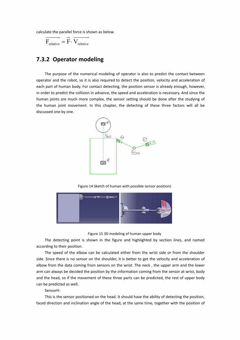
Figure 14 Sketch of human with possible sensor positions
Figure 15 3D modeling of human upper body
The detecting point is shown in the figure and highlighted by section lines, and namedaccording to their position.
The speed of the elbow can be calculated either from the wrist side or from the shoulderside. Since there is no sensor on the shoulder, it is better to get the velocity and acceleration ofelbow from the data coming from sensors on the wrist. The neck , the upper arm and the lowerarm can always be decided the position by the information coming from the sensor at wrist, bodyand the head, so if the movement of these three parts can be predicted, the rest of upper bodycan be predicted as well.
SensorH:This is the sensor positioned on the head. It should have the ability of detecting the position,
faced direction and inclination angle of the head, at the same time, together with the position of

human body, it should be able to obtain the state of the neck, such as position and rotationangle.
So for the head movement, without rotation of the neck, it can be divided into two parts.The first is to choose one direction around the head, the second part is to choose the degree ofinclination. And for the movement of the neck, it is very complex since it contained many smallbones in it. It can rotate around its axis, it can also incline to any direction with any degrees in alarge range. The good thing is that, all of these movements mentioned above can be replaced byother equivalent movement of head. Since the head can’t rotate without the rotation of the neck,the rotation of head can be detected to reflect the rotation of neck. And since when the neckincline to certain direction with certain degrees, the position of head will move in relative way,these two are exactly linear because if one fix his head, he won’t be able to move his neck.
Therefore, to cover the neck and head detecting only by sensors on the head, the functionof the sensors should include: angular sensor around neck axis, inclination direction and degreesensor, and position sensor.
SensorB:This is the sensor positioned on the body, it should be able to detect the position of the
upper body of the operator, and can determine the statues of the neck with the informationcoming from Sensor H.
The movement of the upper body is meaning controlled by waist, and with the same type ofmovement which can be done by head. So the sensors on human body should also have thefunctions of angular sensor around waist axis, inclination direction and degree sensor, andposition sensor.
SensorA:This is the sensor for the arm movement. Considering the position and movement statues
are already clear, in order to use as less as possible the sensor and to guarantee sensor positionwon’t cause big effect to operator movement, the best place is on the wrist. As shown in thefigure, knowing the position of point B and W, the length of the lower arm or the upper arm, aswell as the angle of α and β, the movement states of the whole arm can be pictured. Amongthese parameters mentioned, the position can be obtained by body sensor and the wrist sensor,the angle can also measured at the wrist, and the length of the arm can be input manually beforethe operator using this robot.
It is quiet clear that, the neck, the upper and lower arm is constrained if the position andinclination angle of wrist, body and the head is fixed. So the whole body movement can alwaysbe modeled only by information coming from the sensors at these three position. Further more,by predicting the movement of the head, the body and the wrist, the whole upper bodymovement can be predicted.
For the hand modeling, there are several solutions to choose. In one hand, there are 15knuckles in total, which allows the hand to be the most flexible part of each human. So one wayis to detect the movement of each finger joints using sensors. This method requires at least 10sensors by calculation. And the hand movements can be affected to some extent. Another way isto modeling the hand movement covered space as a whole. The advantage is that the hand won’tbe affected by the sensors, but the impact simulation and prediction will be over estimated, sincethe hand model will be more easy to impact with the robot than the real hand.
Take the calculation of position of the elbow and upper arm by wrist and body sensor as an

example. The position of the shoulder can be easily obtained by human body dimension and thestates of the waist from the sensor. At the same time the position of the wrist and the directionof the lower arm can be read also from the sensor. By calculating considering also the length ofthe lower arm, the position of the elbow is obtained, as well as the position and direction of theupper arm.
7.3.3 Map of control
The control map contains several sub matric in it. First, considering different position ofhuman body will have different pain sensitivity, and the different point on robot arm havedifferent stiffness and function, there should one matrix to decide on which position the contactpoint is of the human body and robot arm. The human body can be divided according to the mainpoint relative. The robot arm can be separated into different groups.
Bot1 Bot2 Bot3 BotnHead1 MapH1Bo1Headm
Body1BodyiArm1
Armj MapA1BonTable 5 Matrix that stores the map impact of each human and robot point
Figure 16 the contact point concerned on human body
The main point on human body can be determined following two steps. The first step is tocover the whole body with detecting points with equal space between each of them. Such as onthe upper arm, 4X3 points are set from shoulder to the elbow. On shoulder, elbow and theposition in the center of the upper arm, four points around the arm are chosen for each positiondue to different pain sensitivity on each side of the arm. The next step is to add the point on thecritical positions on human body, such as the temple on the side of the head, which is verydangerous for the operator during an impact. So the result points are listed in the table and thelayout is shown in the figure.
Head1
Headm
arm1
armj
Body1
Bodyi
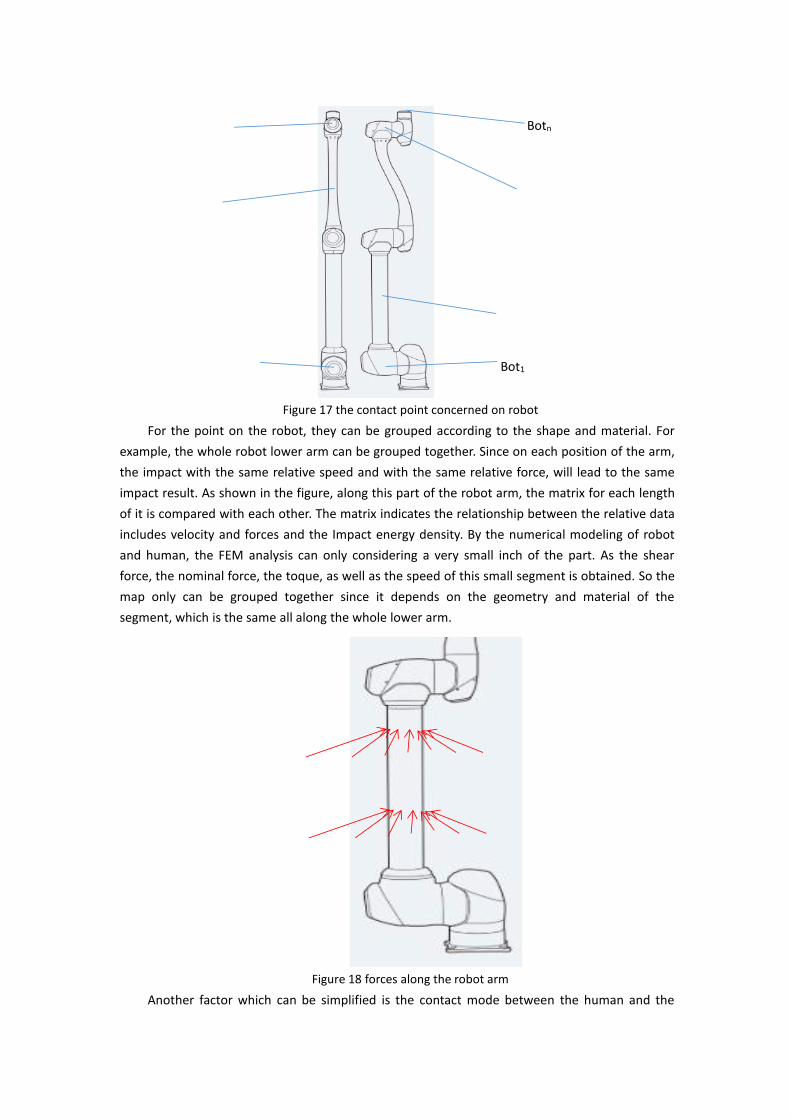
Figure 17 the contact point concerned on robot
For the point on the robot, they can be grouped according to the shape and material. Forexample, the whole robot lower arm can be grouped together. Since on each position of the arm,the impact with the same relative speed and with the same relative force, will lead to the sameimpact result. As shown in the figure, along this part of the robot arm, the matrix for each lengthof it is compared with each other. The matrix indicates the relationship between the relative dataincludes velocity and forces and the Impact energy density. By the numerical modeling of robotand human, the FEM analysis can only considering a very small inch of the part. As the shearforce, the nominal force, the toque, as well as the speed of this small segment is obtained. So themap only can be grouped together since it depends on the geometry and material of thesegment, which is the same all along the whole lower arm.
Figure 18 forces along the robot arm
Another factor which can be simplified is the contact mode between the human and the
Bot1
Botn
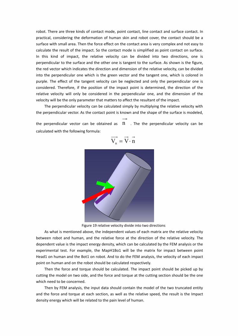
robot. There are three kinds of contact mode, point contact, line contact and surface contact. Inpractical, considering the deformation of human skin and robot cover, the contact should be asurface with small area. Then the force effect on the contact area is very complex and not easy tocalculate the result of the impact. So the contact mode is simplified as point contact on surface.In this kind of impact, the relative velocity can be divided into two directions, one isperpendicular to the surface and the other one is tangent to the surface. As shown is the figure,the red vector which indicates the direction and dimension of the relative velocity, can be dividedinto the perpendicular one which is the green vector and the tangent one, which is colored inpurple. The effect of the tangent velocity can be neglected and only the perpendicular one isconsidered. Therefore, if the position of the impact point is determined, the direction of therelative velocity will only be considered in the perpendicular one, and the dimension of thevelocity will be the only parameter that matters to affect the resultant of the impact.
The perpendicular velocity can be calculated simply by multiplying the relative velocity withthe perpendicular vector. As the contact point is known and the shape of the surface is modeled,
the perpendicular vector can be obtained as n . The the perpendicular velocity can be
calculated with the following formula:
nVVn
Figure 19 relative velocity divide into two directions
As what is mentioned above, the independent values of each matrix are the relative velocitybetween robot and human, and the relative force at the direction of the relative velocity. Thedependent value is the impact energy density, which can be calculated by the FEM analysis or theexperimental test. For example, the MapH1Bo1 will be the matrix for impact between pointHead1 on human and the Bot1 on robot. And to do the FEM analysis, the velocity of each impactpoint on human and on the robot should be calculated respectively.
Then the force and torque should be calculated. The impact point should be picked up bycutting the model on two side, and the force and torque at the cutting section should be the onewhich need to be concerned.
Then by FEM analysis, the input data should contain the model of the two truncated entityand the force and torque at each section, as well as the relative speed, the result is the Impactdensity energy which will be related to the pain level of human.

The result of the FEM should all be simulated and stored in the control unit in order to samethe time of FEM analysis during the digital twin application and to guarantee the characteristicsof real time. The map which relates to the relative speed and the relative force is shown as below.For each pair of impact point, there will be one certain IDE map for the control unit to read theresultant IDE by the calculated relative force and relative velocity.
Figure 20 possible layout of map of impact
The IED itself is not sufficient enough to decide whether it is an impact that will lead to painand injury to human. With the same IED, the pain level will be different on different part ofhuman body. So a coefficient of pain should be set according to the pain sensitivity of differentpart of human body. As the previous matrix is also related to human body position, the outputdata IED can then directly transfer into the pain level by multiplies this coefficient.
ysensitivitPain IEDLevelPain
Then this pain level can be used to compare with the pain level limit settled according to thesafety standard of human robot collaboration and also the position of each point on the humanbody.

7.3.4 Logic of control
Figure 21 logic flow chart of digital twin control with Doosan Cobot
The logic is shown as above, which maximize the advantages of digital twin, which ispredictability and accuracy. The prediction is done by the first three steps, as the modeling is fullybuilt and all the movement data is obtained either by sensors or read from robot software, themovement states can be predicted in a short period ahead. This ahead period tahead should be in arange with relate to the reaction time of human and the calculation time required by the digitaltwin system.
reactionaheadcmdcomhcomlFv ttttttt
In which tv is the time for calculate the relative velocity;tF is the time for calculate the relative force along the direction of relative velocity. This time
Keep the current motion state to do system simulation
Simulate the state of the system in tahead second ahead
Determine if there is a contact
Calculate the pain levelwith condition of motorderating and compare todecide if it is necessary toavoid the contact
Send warning and stop the robot
Derate themotor and keepthe Power andTorque low untilthe contact end,then runs innormal state again
Determine if the contact point is atthe tool on robot
Determine if the contact point is atthe human guidance area of the robot
Calculate the pain levelwithout derating of motorand compare to decide if itis necessary to avoid thecontact

includes both the calculation at normal operation condition and at derating working condition.tcoml is the time required to do the comparison between the resultant pain level and the pain
level limit under derating condition;tcoml is the time required to do the comparison between the resultant pain level and the pain
level limit under normal condition;treaction is the reaction time of human. This limit is to increase the predictability of human
movement, since if the time ahead is too large, the human movement will becomeunpredictable.
The other steps are set to determine whether an impact occurs or not. The most importantissue in this part is to separate the human guidance to the accidentally contact. Or the systemwon’t work correctly. For example, the motor will derate and the robot will slow down every timethe human touch the button on it, and if the human guidance is recognized as an impact whichwill cause pain and injury, the robot will stop and send warning. To avoid these situations fromhappening, an area of human guidance is designed on the robot, and the system can rundifferent algorithm in this area.

8. Analyze of the results
The time ahead can only be set in a very small range, since it can’t be larger than thereaction time of human, which is already very low. It also need to be larger than the calculationtime and process time of the system control unit, which depends also on the workingenvironment, and can be sometimes even larger than the human reaction time.
The hand modeling as a whole lead to an over estimation of the impact severity. Since thesystem will consider it as an contact even your finger is not contact with the robot. This will affecta lot the performance of human guidance, and should also be considered in the logic byseparating the situation according to the operation area.
There are many maps stored in the system, which depends on the geometric and material ofrobot and human body. Therefore as the operator change to another person, the whole mapshould be changed, which will cost a lot of time. One way for this is to store the map of human indifferent height in advance, by the operator’s height, the right series of matrix will be chosen.Another way is to let the operator wear the equipment and do certain movement to let thesystem calibrate the data in the maps.
The digital application in this thesis is far from completed. In terms of accuracy, thenumerical modeling and the modeling of the hand is simplified to make the calculation more easy.The same for the modeling of the human body, the thickness and shape of the body and arm isnot considered. These factors can be neglected compared with other parameters in most cases,but with the operations which need high accuracy, this digital twin application methodology needto be improved. In terms of the real time characteristic, the usage of IDE map and thesimplification of the modeling has highly increase the efficiency of the calculation and reduce thereaction delay of the control unit. This delay is still far from achieving the real time effect, furtherefforts need to be taken to decrease this time.

9. Conclusions
9.1 The digital twin application in this thesis
This thesis discussed a way of safety improvement of collaborative robot environment bydigital twin application. With 3D modeling, numerical modeling, FEM analysis and big dataprocessing ability, the digital twin application can be built. By storing the numerous data of theresult of collision into the control unit and set the limit on parameters that relative to thestandard of safety, the digital twin can simulate in ahead of time to determine whether adangerous impact is about to happen or not, and can control the physical robot in a reasonablelogic to avoid the danger as well as save the time.
The big data stored in the control unit is the key point to achieve real-time characteristic ofthe digital twin application, since the calculation should be easy enough. The compromise ismade with obtaining a more accurate virtual simulation of collision, which needs a lot ofcomputations costing time. So the FEM system will be run in back ground to update the data andguarantee the accuracy of the system
For the human model in the digital twin, the more sensor on human, the more accurate thevirtual simulation of human body movement. However, this will also increase the difficulty ofhuman operation. The number of the sensors is then be reduced to minimum on the premise ofdetecting the complete movement of human body. A compromise layout is used by only assignsensors on head, waist and the wrist, which highly reduced burden and weight on the operator.
By reasonably setting the Injury Index Limit in the map, and cooperate with the logic of theprogram in the control unit, the possible human guidance action can be done satisfying thecollaborative robot safety standard. All the impact situations with different velocity and positionare divided into groups according to the relative velocity and the shape characteristics of therobot and human. This is a very effective and valid way to reduce the calculation time of thedigital twin application.
All in all, the digital twin application is a strong method which can be used to guarantee thesafety environment of human robot collaboration by predicting the danger in the virtual spaceand control the robot in physical space to avoid the dangerous accident from happening.
9.2 Future work
Further decrease the time between the detecting of contact and action by the control unit.The shorter this time, the stronger the predictability. Since the time ahead can also be reduced,and the movement of the operator will be more predictable.
The hand modeling in this thesis is not discussed in detail. However, fingers is the part ofhuman body that have the most possibility of contact with the robot. So detail modeling shouldbe also be added in the future, with detecting method which will not disturb or influence themovement of the fingers.
The thickness of human body is not considered in this thesis, which will lead to tolerance

when determine the impact severity. If the operator is fatter than the model, the impact will beunderestimated, on the contrary, if the operator is thin, the impact will be overestimated, thedata of the detailed human body of the operator should be considered in the future.
The constrains of degree of freedom of human joints movement should be considered whenrun the FEM analysis to get the Impact Density Energy. As with the same position of contact, thesame relative speed and the same relative force and torque, if the operator can not move hisbody along the direction of the force applied, the damage will be mach bigger than the case theoperator can move his body freely along the direction of the force. This can be considered addanother parameter multiply to the final index, which is related to the constrains of all the humanbody joints.

Acknowledgement
Thanks to the supervisor of this thesis Professor DEMICHELA MICAELA for providing me withthe general idea, and correcting me when I study into the wrong direction. The online libraryresources of Polytechnic University of Turin have provided me with many references and help forthis thesis. At the same time, I would like to thank the leaders of the internship company for theirsupport and encouragement of my graduation project. They have concerned about the progressof my thesis many times and reduced my work stress so that I can have enough time to study andfinish this project.

Reference
[1] Söderberg, R., Wärmefjord, K., Carlson, J. S., & Lindkvist, L. (2017)[2] "Minds + Machines: Meet A Digital Twin". Youtube. GE Digital. Retrieved 26 July 2017.[3] The Development Trend of Mechanical Safety-Intelligent Security. Liu Zhiyong, Li Qin[4] BOSCHERT S. ROSEN R. Digital twin-the Simulation aspect[M]//Mechatronic Futures. Berlin,Germany: Springer-Verlag, 2016[5] GRIEVES M. VICKERS J. Digital twin: mitigating unpredictable, undesirable emergentbehavior in complex systems[M]//Transdisciplinary Perspectives on Complex Systems. Berlin,Germany: Springer-Verlag, 2017[6] TUEGEL EJ,INGRAFFEA AR,EASON TG, et al. Reengineering aircraft structural life predictionusing a digital twin[J]. International Journal of Aerospace Engineering, 2011 DOI: 10.1155/2011/154798[7] SIEMENS. The digital twin[EB/OL].(2015-11-17)[8] FOURGEAU E, GOMEZ E, ADLI H, et al. System engineering workbench for multi-viewssystems methodology with 3DEXPERIENCE Platform.[M]//Complex Systems Design &Management Asia. Berlin, Germany: Spring International Publishing, 2016[9] FLORIAN B. DAVIS M. A digital twin for production planing based on cyber-physicalsystems[M]//ScienceDirect. Gulf of Naples, Italy, 2018[10] NIKI K. CHRISTOS G. Digital twin for adaption of robots’ behavior in flexible roboticassembly lines[11] TIMO M. TIMO S. ILARI M. JARI M. Dynamic safety system for collaboration of operatorsand industrial robots.//Open Engineering:formerly Central European Journal of Engineering, 2019[12] ISO/TS 15066:2016(en) Robots and robotic devices — Collaborative robots[13] Christopher Harper. Gurvinder Virk. Towards the Development of International SafetyStandards for Human Robot Interaction//Springer Science & Business Media BV 2010. Publishedonline: 26 June 2010[14] Adam J. , Kerry A. Injury prediction in a side impact crash using human body modelsimulation//Accident Analysis and Prevention 64 (2014) 1–8[15] B. Povse, S. Haddadin. A tool for the evaluation of human lower arm injury: approach,experimental validation and application to safe robotics.[16] Arthur C. Croft. The neck injury criterion: future considerations//Accident Analysis andPrevention 34 (2002) 247–255. accepted 1 January 2001

Annex 1
%% computation of trajectory of point EE
for i=1:361
q1=(i-1)*pi/180; q2=(i-1)*pi/180; q3=(i-1)*pi/180; q4=(i-1)*pi/180; q5=(i-1)*pi/180;
q6=(i-1)*pi/180; % [rad], [rad],[m] % define the joint variables
%transformation matrixes and vectors
teta1=q1;
A10o=denhar_en01(alfa1,a1,d1,teta1); % (homogeneous) matrix 4x4: positioning of ref frame %O1
with respect to frame O0
alfa2=q2; teta2=q3;
A21o=denhar_en01(alfa2,a2,d2,teta2+180); % (homogeneous) matrix 4x4: positioning of ref
frame %O2 with respect to frame O1
alfa3=q4;
A32o=denhar_en01(alfa3,a3,d3,teta3); % (homogeneous) matrix 4x4: positionining of ref frame %O3
with respect to frame O2
teta4=q5;
A43o=denhar_en01(alfa4,a4,d4,teta4); % (homogeneous) matrix 4x4: positionining of ref frame %O4
with respect to frame O3
alfa5=q6;
A54o=denhar_en01(alfa5,a5,d5,teta5); % (homogeneous) matrix 4x4: positionining of ref frame %O5
with respect to frame O4
A65o=denhar_en01(alfa6,a6,d6,teta6); % (homogeneous) matrix 4x4: positionining of ref frame %O6
with respect to frame O5
A20o=A10o*A21o; % (homogeneous) matrix 4x4: positioning of ref frame O2 with respect to %frame
O0
A30o=A10o*A21o* A32o; % (homogeneous) matrix 4x4: positioning of ref frame O3 with respect
to %frame O0
A40o=A10o*A21o* A32o*A43o; % (homogeneous) matrix 4x4: positioning of ref frame O4 with respect
to %frame O0
A50o=A10o*A21o* A32o*A43o*A54o; % (homogeneous) matrix 4x4: positioning of ref frame O5 with
respect to %frame O0
A60o=A10o*A21o* A32o*A43o*A54o*A65o; % (homogeneous) matrix 4x4: positioning of ref frame O6 with
respect to %frame O0
pEE0o(:,i)=A60o*EE3o; %position of point EE in frame O0
end
%% plot trajectory of point EE
figure(1)
plot3(pEE0o (1,:), pEE0o (2,:), pEE0o (3,:),'g');
xlabel('axis x')
ylabel('axis y')
zlabel('axis z')
legend('trajectory EE');

%% wire-frame representation of the multibody system
% initial configuration
i=1;
q1=(i-1)*pi/180; q2=(i-1)*pi/180; q3=(i-1)*pi/180; q4=(i-1)*pi/180; q5=(i-1)*pi/180;
q6=(i-1)*pi/180; % [rad], [rad],[m] % define the joint variables
%transformation matrixes and vectors
pOo=[0 0 0 1]'; %position vector of the global frame origin in the global
frame 0
teta1=q1;
A10o=denhar_en01(alfa1,a1,d1,teta1); % (homogeneous) matrix 4x4: positioning of ref frame %O1
with respect to frame O0
pO10o=A10o(:,4);
alfa2=q2;
A21o=denhar_en01(alfa2,a2,d2,teta2); % (homogeneous) matrix 4x4: positioning of ref frame %O2
with respect to frame O1
A20o=A10o*A21o;
pO20o=A20o(:,4);
teta3=q3+pi;
A32o=denhar_en01(alfa3,a3,d3,teta3); % (homogeneous) matrix 4x4: positionining of ref frame %O3
with respect to frame O2
A30o=A20o*A32o;
pO30o=A30o(:,4);
alfa4=q4;
A43o=denhar_en01(alfa4,a4,d4,teta4); % (homogeneous) matrix 4x4: positionining of ref frame %O4
with respect to frame O3
A40o=A30o*A43o;
pO40o=A40o(:,4);
teta5=q5;
A54o=denhar_en01(alfa5,a5,d5,teta5); % (homogeneous) matrix 4x4: positionining of ref frame %O5
with respect to frame O4
A50o=A40o*A54o;
pO50o=A50o(:,4);
alfa6=q6;
A65o=denhar_en01(alfa6,a6,d6,teta6); % (homogeneous) matrix 4x4: positionining of ref frame %O6
with respect to frame O5
A60o=A50o*A65o;
pO60o=A60o(:,4);
punti_om=[pOo pO10o pO20o pO30o pO40o pO50o pO60o];
punti=punti_om(1:3,:);
% plot initial configuration
hold on
figure(1)
plot3(punti(1,:),punti(2,:),punti(3,:),'b'),grid

axis equal
xlabel('x');ylabel('y');zlabel('z')
joint_rev_01(.1,.3,20,A10o,'blu')
joint_rev_01(.1,.3,20,A20o,'blu')
joint_rev_01(.1,.3,20,A30o,'blu')
% final configuration
i=46;
q1=(i-1)*pi/180; q2=(i-1)*pi/180; q3=(i-1)*pi/180; q4=(i-1)*pi/180; q5=(i-1)*pi/180;
q6=(i-1)*pi/180; % [rad], [rad],[m] % define the joint variables
%transformation matrixes and vectors
pOo=[0 0 0 1]'; %position vector of the global frame origin in the global
frame 0
teta1=q1;
A10o=denhar_en01(alfa1,a1,d1,teta1); % (homogeneous) matrix 4x4: positioning of ref frame %O1
with respect to frame O0
pO10o=A10o(:,4);
alfa2=q2; teta2=q3;
A21o=denhar_en01(alfa2,a2,d2,teta2+180); % (homogeneous) matrix 4x4: positioning of ref
frame %O2 with respect to frame O1
A20o=A10o*A21o;
pO20o=A20o(:,4);
alfa3=q4;
A32o=denhar_en01(alfa3,a3,d3,teta3); % (homogeneous) matrix 4x4: positionining of ref frame %O3
with respect to frame O2
A30o=A20o*A32o;
pO30o=A30o(:,4);
teta4=q5;
A43o=denhar_en01(alfa4,a4,d4,teta4); % (homogeneous) matrix 4x4: positionining of ref frame %O4
with respect to frame O3
A40o=A30o*A43o;
pO40o=A40o(:,4);
alfa5=q6;
A54o=denhar_en01(alfa5,a5,d5,teta5); % (homogeneous) matrix 4x4: positionining of ref frame %O5
with respect to frame O4
A50o=A40o*A54o;
pO50o=A50o(:,4);
A65o=denhar_en01(alfa6,a6,d6,teta6); % (homogeneous) matrix 4x4: positionining of ref frame %O6
with respect to frame O5
A60o=A50o*A65o;
pO60o=A60o(:,4);
punti_om=[pOo pO10o pO20o pO30o pO40o pO50o pO60o];
punti=punti_om(1:3,:);
% plot final configuration
hold on

figure(1)
plot3(punti(1,:),punti(2,:),punti(3,:),'r'),grid
axis equal
xlabel('x');ylabel('y');zlabel('z')
joint_rev_01(.1,.3,20,A10o,'red')
joint_rev_01(.1,.3,20,A20o,'red')
joint_rev_01(.1,.3,20,A30o,'red')
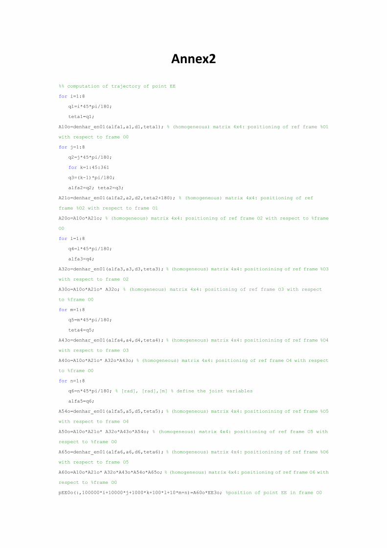
Annex2
%% computation of trajectory of point EE
for i=1:8
q1=i*45*pi/180;
teta1=q1;
A10o=denhar_en01(alfa1,a1,d1,teta1); % (homogeneous) matrix 4x4: positioning of ref frame %O1
with respect to frame O0
for j=1:8
q2=j*45*pi/180;
for k=1:45:361
q3=(k-1)*pi/180;
alfa2=q2; teta2=q3;
A21o=denhar_en01(alfa2,a2,d2,teta2+180); % (homogeneous) matrix 4x4: positioning of ref
frame %O2 with respect to frame O1
A20o=A10o*A21o; % (homogeneous) matrix 4x4: positioning of ref frame O2 with respect to %frame
O0
for l=1:8
q4=l*45*pi/180;
alfa3=q4;
A32o=denhar_en01(alfa3,a3,d3,teta3); % (homogeneous) matrix 4x4: positionining of ref frame %O3
with respect to frame O2
A30o=A10o*A21o* A32o; % (homogeneous) matrix 4x4: positioning of ref frame O3 with respect
to %frame O0
for m=1:8
q5=m*45*pi/180;
teta4=q5;
A43o=denhar_en01(alfa4,a4,d4,teta4); % (homogeneous) matrix 4x4: positionining of ref frame %O4
with respect to frame O3
A40o=A10o*A21o* A32o*A43o; % (homogeneous) matrix 4x4: positioning of ref frame O4 with respect
to %frame O0
for n=1:8
q6=n*45*pi/180; % [rad], [rad],[m] % define the joint variables
alfa5=q6;
A54o=denhar_en01(alfa5,a5,d5,teta5); % (homogeneous) matrix 4x4: positionining of ref frame %O5
with respect to frame O4
A50o=A10o*A21o* A32o*A43o*A54o; % (homogeneous) matrix 4x4: positioning of ref frame O5 with
respect to %frame O0
A65o=denhar_en01(alfa6,a6,d6,teta6); % (homogeneous) matrix 4x4: positionining of ref frame %O6
with respect to frame O5
A60o=A10o*A21o* A32o*A43o*A54o*A65o; % (homogeneous) matrix 4x4: positioning of ref frame O6 with
respect to %frame O0
pEE0o(:,100000*i+10000*j+1000*k+100*l+10*m+n)=A60o*EE3o; %position of point EE in frame O0

end
end
end
end
end
end