two beam-to-column
TRANSCRIPT

.A .1 .......
- V'" -..,
REPORT NO.
UCB/EERC-86/05
APRIL 1986
PB87-124301
EARTHQUAKE ENGINEERING RESEARCH CENTER
TWO BEAM-TO-COLUMNWEB CONNECTIONS
by
KEH-CHYUAN TSAI
EGOR P. POPOV
COLLEGE OF ENGINEERING
UNIVERSITY OF CALIFORNIA • Berkeley, CaliforniaREPRODUCED BY
U.S. DEPARTMENT OF COMMERCENATIONAL TECHNICAL
INFORMAnON SERVICESPRINGFIELD, VA. 22161
".l ...


50272 -10 --, ~
REPORT DOCUMENTATION 11. REPORT NO • _' '
PAGE UCBjEERC-06j054. Titije and Subtitle
"Two Beam-To-Co1umn l~eb Connecti ons II
I3. Recipient's Accession No.
PBS 7 1,'c~ <.t .~) 0 15. Report Date
April, 19866.
7. Jl.lJtl)or(!;l, T'K.en-Lnyuan sal and Egor P. Popov8. Performing Organization Rept. No.
UCBjEERC-86j059. Performing Organization Name and Address
Earthquake Engineering Research CenterUniversity of California, Berkeley1301 South 46th StreetRichmond, Ca. 94804
12. Sponsoring Organization Name and Address
National Science Foundation1800 G street, NWWashington, DC 20050
15. Supplementary Notes
16. Abstract (limit: 200 words)
10. Project/Task/Work Unit No.
11. Contract(C) or Graot(G) No.
(C)
(G)
13. Type of Report & Period Covered
~----------------t
14.
In this report test results for experiments on two half-scale beam-to-co1umn webmoment connections are described. In the first experiment an innovative concepta'imed at enhancing the ductility and strength of the connection by adding two pairsof reinforcing ribs was explored. In the second experiment the behavior of similarconnections but without reinforcing ribs-a type that is common in practice-wasevaluated. The new design was relatively simple to fabricate and the reinforcedconnection exhibited excellent strength and ductility characteristi<::s. The resultsshow that these moment connections are suitable for severe seismic service.
17. Document Analysis a. Descriptors
steelconnectionsearthquake
b. Identifiers/Open-Ended Terms
c. COSATI Field/Group
seismicductility
22. Price
18. Avail~bility Statemen~
Release Unlimited
19. Security Class (This Report) 21. No. of Pagesi , !'. /
1---,1:.L(La,,-j'-'(~'-"/-';'-:L:=:;~.i.-f-C.-;-' ..'-",,=Co.OJj.i.-·----1I-"".rc...,-'------20. Securlt¥ Class (T':!is Page)!'
i)J/l (~/·~1i,,~\~-/ ·+r \2--[~1~ee ANSI-Z39.18) See Instructions on Reverse OPTIONAL FORM 272 (4-77)
(Formerly NTlS-35)Department of Commerce
TWO BEAM-TO-COLUMN WEB CONNECTIONS
ALTERNATIVE DESIGNS AND TESTS
OF TWO
BEAM-TO-COLUMN WEB SEISMIC MOMENT CONNECTIONS
by
Keh-Chyuan TsaiGraduate Student
Egor P. PopovProfessor Emeritus of Civil Engineering
University of California, Berkeley
Report No. UCB/EERC-86!05Earthquake Engineering Res€arch Center
University of CaliforniaBerkeley, California
April 1986

!-
ABSTRACT
In this report test results for experiments on two half-scale steel beam-to-column web
moment connections are described. In the first experiment an innovative concept aimed at
enhancing the ductility and strength of the connection by adding two pairs of reinforcing ribs
was explored. In the second experiment the behavior of similar connections but without rein
forcing ribs-a type that is common in practice-was evaluated. The new design was rela
tively simple to fabricate and the reinforced connection exhibited excellent strength and duc
tility characteristics. The results show that these moment connections are suitable for severe
seismic service.

- II -
ACKNOWLEDGMENTS
The authors are pleased to acknowledge with gratitude the excellent support provided by
the Department of Civil Engineering machine shop and to Mr. Roy M. Stephen. It is also a
pleasure to express gratitude to doctoral student James Rides for offering valuable suggestions
during preparation of the experiments as well as to doctoral student Michael Englehardt and
Dr. Kazuhiko Kasai for assistance with the tests. The donation of the steel column stub by
Herrick Corporation is much appreciated.

- 111 -
Table of Contents
ABSTRACT .
ACKNOWLEDGMENTS 11
TABLE OF CONTENTS 111
LIST OF FIGURES v
CHAPTER 1 INTRODUCTION .
1.1 General .
1.2 Moment-Resisting Steel Frame .
1.3 Objective and Scope 2
CHAPTER 2 EXPERIMENTAL SYSTEM 3
2.1 Selection of Subassemblages 3
2.2 Description of Test Specimens 3
2.3 Experimental Set-Up 4
2.4 Instrumentation 5
2.5 Loading Sequence 5
CHAPTER 3 EXPERIMENTAL RESULTS 7
3.1 General 7
3.2 Test Results 7
3.3 Summary 9
CHAPTER 4 DISCUSSION OF RESULTS 11
4.1 General 11
4.2 Analytical Comparisons 11
CHAPTER 5 CONCLUSIONS 15
5.1 Summary 15

- iv -
5.2 Conclusions 15
5.3 Future Research Needs 16
REFERENCES 17

- v -
LIST OF FIGURES
Figure 1.1 Steel Beam-to-Column Moment Connections
Figure 1.2 General View of New Design
Figure 2.1 Subassemblage of Beam-to-Column Web Moment Connection
Figure 2.2 Mounting Arrangement of Specimen
Figure 2.3 Connection Detail (Specimen 1)
Figure 2.4 Connection Detail (Specimen 2)
Figure 2.5 General View of Specimen
Figure 2.6 Typical Slip Gage
Figure 2.7 Typical Set-Up for Rotation Measurement
Figure 2.8 Instrumentation at Joint
Figure 2.9 Loading Sequence (Specimen 1)
Figure 2.10 Loading Sequence (Specimen 2)
Figure 3.1 Column Rotation at Beam-Column Joint for Specimen 1 and 2
Figure 3.2 Cantilever Beam Load vs. Beam End Displacement (Specimen 1)
Figure 3.3 Local Buckling of Beam Bottom Flange (Specimen 1)
Figure 3.4 Local Buckling of Beam Top Flange (Specimen 1)
Figure 3.5 Local Buckling of Beam Web (Specimen 1)
Figure 3.6 Yield Pattern at Top Continuity Plate (Specimen 1)
Figure 3.7 Yield Pattern at Beam Web (Specimen 1)
Figure 3.8 Yield Pattern at Shear Tab (Specimen 1)
Figure 3.9 Cantilever Beam Load vs. Beam End Displacement (Specimen 2)

- VI -
Figure 3.10 Flaking of Whitewash on Bottom Flange (Specimen 2)
Figure 3.11 Crack Initiation on Beam Top Flange (Specimen 2)
Figure 3.12 Crack Propagation on Beam Top Flange (Specimen 2)
Figure 3.13 Specimen 2 after Failure
Figure 3.14 Slippage between Beam Web and Shear Tab
Figure 4.1 Beam Moment Capacity and Applied Moment
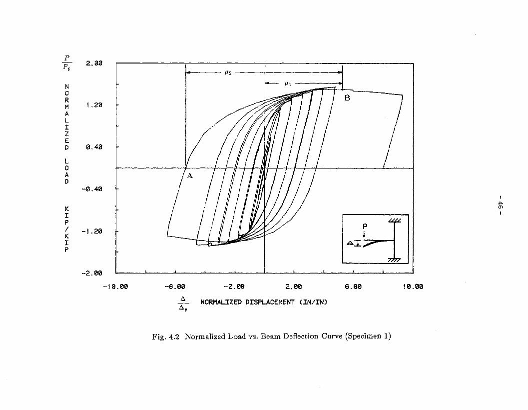
Figure 4.2 Normalized Load vs. Beam Deflection Curve (Specimen 1)
Figure 4.3 Normalized Load vs. Beam Deflection Curve (Specimen 2)
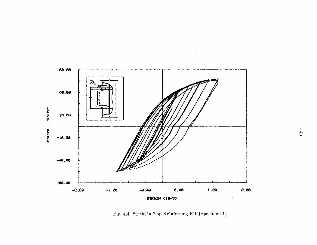
Figure 4.4 Strain in Top Reinforcing Rib (Specimen 1)
Figure 4.5 Strain in Bottom Reinforcing Rib (Specimen 1)
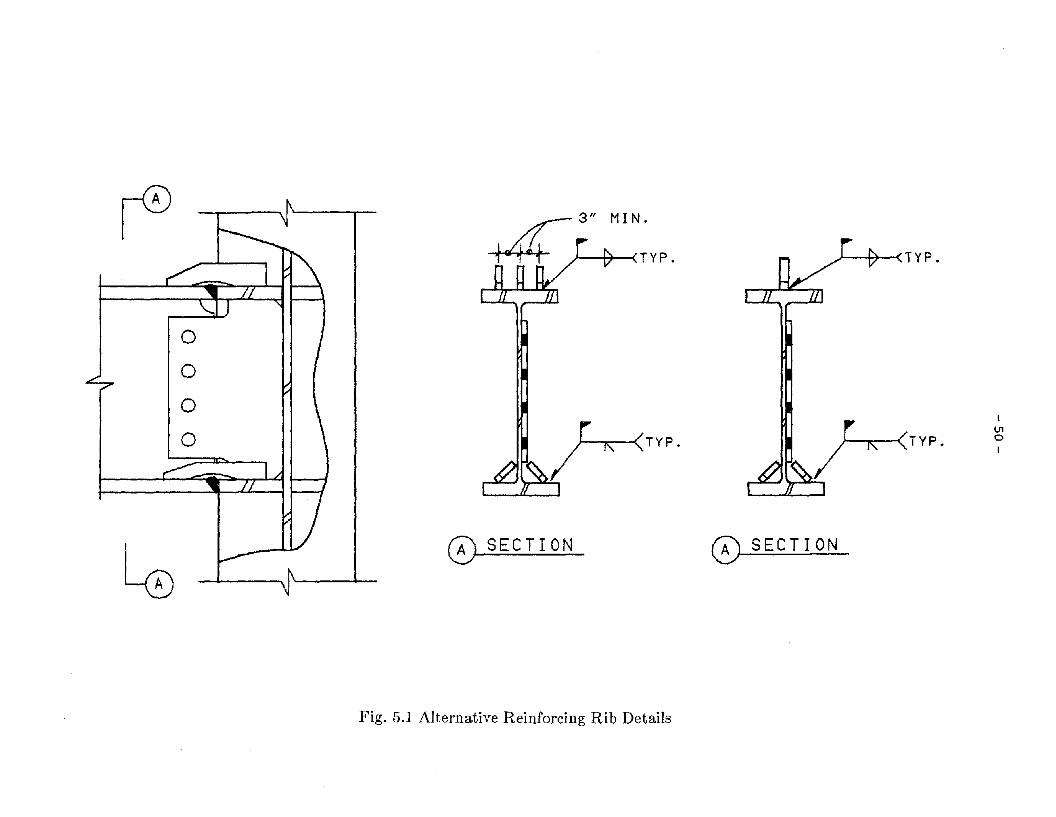
Figure 5.1 Alternative Reinforcing Rib Details

~/-
CHAPTER 1 INTRODUCTION
1.1 General
In current U.S. practice, the analysis and design of building structures under loads are
typically carried out using elastic theory [1,2]. The design of earthquake-resistant structures is
therefore challenging because it is not economical to design structures to resist severe earth
quakes elastically, especially since such severe ground motions rarely occur during the service
life of a structure. A compromise approach is consequently employed [3,4]. First, under
moderate earthquake shaking, serviceability and functionality are to be maintained, requiring
that a structure be sufficiently stiff to limit the story drift so that damage to nonstructural ele
ments is minimized. Secondly, under major earthquake shaking, a structure is permitted to
undergo inelastic action, but must not collapse. This requirement establishes the need for a
structural system capable of absorbing and dissipating energy. Current building codes adopt
the above concept and specify a minimum lateral load required for elastic analysis and design
[2,5,6]. In building structures designed according to this approach inelastic deformation of
members is allowable during major earthquakes, thereby dissipating the energy induced by the
ground motion.
1.2 Moment-Resisting Steel Frame
The steel moment-resisting frame (MRF) is the structural steel framing system most fre
quently used in earthquake-resistant design [22]. The MRF can be designed to be ductile and
to dissipate large amounts of energy during a severe earthquake [8,22,23]. The demand for
energy dissipation on steel MRFs designed according to current building code requirements
may, however, be very high in the event of a major earthquake [22]. The capacity of an MRF
to dissipate energy will therefore primarily depend on the adequacy of the strength and ductil
ity of the MRF at beam-to-column joints. Two types of connection are commonly encoun
tered in beam-to-column joints of steel moment-resisting frames (Fig. 1.1). One is a

- 2 -
connection to the column flange, and the other occurs at the corners of any three-dimensional
framing system where beams are framed into the webs of columns. The latter type of connec
tion is very important for tall tubular structural systems in which corner spandrel beams
simultaneously apply moments and shears to corner columns to develop tube action [24].
1.3 Objective and Scope
Experimental research on steel beam-to-column moment connections has focused pri
marily on beam framing into column flanges [7-14], and little research on the behavior of
beam-to-column web connections has been carried out [15-19]. Available experimental results
have shown, unfortunately, that certain types of connection detail commonly used to connect
beams to column webs perform very poorly under cyclic loading[ 16,17,26]. Accordingly,
there is a great need to improve present methods used to detail such connections. A test pro
gram in which the behavior of a novel design of beam-to-column web moment connection
was assessed and its behavior was compared to the best design used in current practice was
therefore carried out. The concept developed for the new connection consists in reducing the
stress concentration at the beam-to-column juncture by adding special ribs. The general
details of this new design are shown in Fig. 1.2. The scope of the test program was as follows:
1. To obtain experimentally the cyclic strength and ductility for the reinforced con-
nection;
2. To repeat the experiments for a connection commonly used in practice, and to
compare the results; and
3. In both experiments to obtain experimental data on bolt slippage under cyclic
loading, an especially important objective.

- 3 -
CHAPTER 2 EXPERIMENTAL SYSTEM
2.1 Selection of Subassemblages
Examination of the force distribution in a typical MRF under severe lateral load reveals
that it is reasonable to assume that the inflection points are located at mid-height of the
columns and mid-span of the beams. The subassemblage shown in Fig. 2.1 was made from a
W18x40 section. The member sizes were restricted by the need to limit the complexity of the
test specimen and by the available materials. The column used for Specimen 1 was re-used in
Specimen 2, and the two beams were cut from the same piece of rolled section. The material
used for the two specimens-including beam sections, column, continuity plates, shear tabs,
and reinforcing ribs-was ASTM A36 steel. All welding was accomplished using AWS E70
electrodes employing the shielded metal arc process [20]. The experimental set-up, including
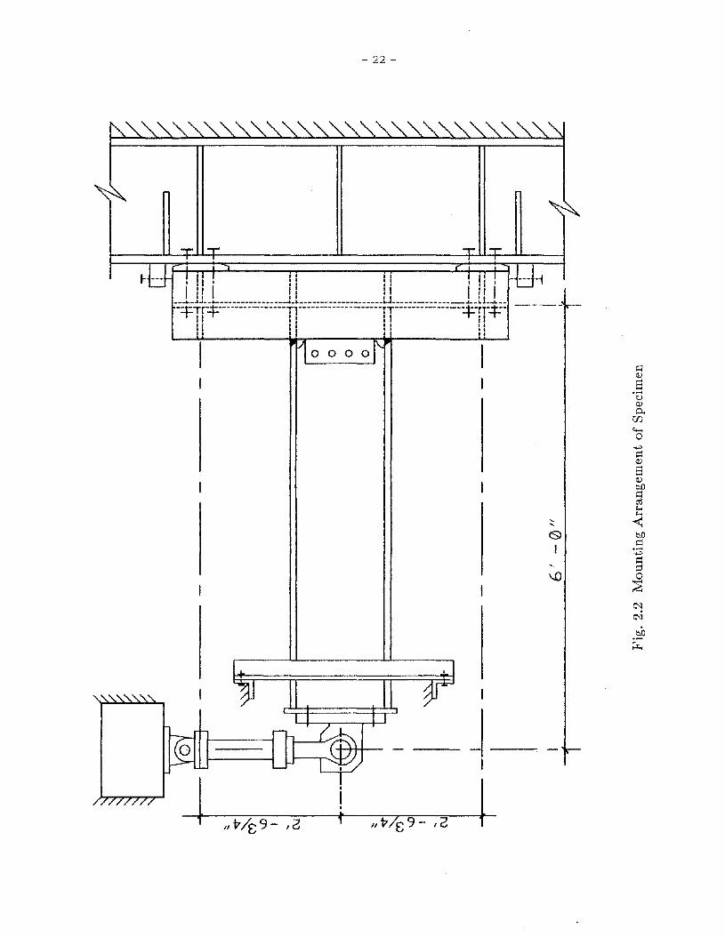
a test specimen, is shown in Fig. 2.2. Considering strain hardening of the beam, it was
estimated that the column would remain elastic during the test. Although the effect of axial
load in the column was not considered in this investigation, it is believed that the responses
of the subassemblages provide a good indication of behavior that can be anticipated in actual
assemblages in building frames.
2.2 Description of Test Specimens
Specimen 1
The beam and column were of A36 steel fabricated from W18X40 and WI2X133 sec
tions, respectively. Two pairs of continuity plates and one shear tab were welded to the
column with fillet welds. For each specimen, the W18X40 beam was then bolted to the
column using four I-in. diameter A325-X bolts through 1/16-in. oversize holes on the beam
web and shear tab. The beam flanges were groove-welded to the continuity plates using full
penetration welds with 1/4-in. root openings. The back-up plates, 3/8 in. by 1 in., remained
in place after the welds were completed. The overall fabrication details are shown in Fig. 2.3.
- 4 -
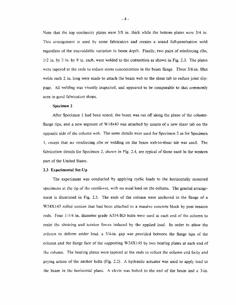
Note that the top continuity plates were 5/8 in. thick while the bottom plates were 3/4 in.
This arrangement is used by some fabricators and creates a sound full-penetration weld
regardless of the unavoidable variation in beam depth. Finally, two pairs of reinforcing ribs,
1/2 in. by 2 in. by 9 in. each, were welded to the connection as shown in Fig. 2.3. The plates
were tapered at the ends to reduce stress concentration in the beam flange. Three 3/8-in. fillet
welds each 2. in. long were made to attach the beam web to the shear tab to reduce joint slip
page. All welding was visually inspected, and appeared to be comparable to that commonly
seen in good fabrication shops.
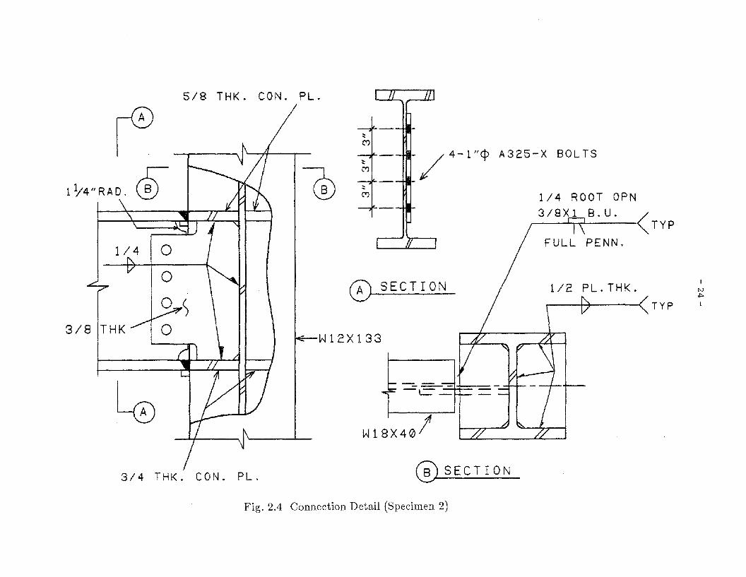
Specimen 2
After Specimen 1 had been tested, the beam was cut off along the plane of the column
flange tips, and a new segment of W18x40 was attached by means of a new shear tab on the
opposite side of the column web. The same details were used for Specimen 2 as for Specimen
1, except that no reinforcing ribs or welding on the beam web-to-shear tab was used. The
fabrication details for Specimen 2, shown in Fig. 2.4, are typical of those used in the western
part of the United States.
2.3 Experimental Set-Up
The experiment was conducted by applying cyclic loads to the horizontally mounted
specimens at the tip of the cantilever, with no axial load on the column. The general arrange
ment is illustrated in Fig. 2.5. The ends of the column were anchored to the flange of a
W24X145 rolled section that had been attached to a massive concrete block by post tension
rods. Four 1-1/4 in. diameter grade A354-BD bolts were used at each end of the column to
resist the shearing and tension forces induced by the applied load. In order to allow the
column to deform under load, a 3/4-in. gap was provided between the flange tips of the
column and the flange face of the supporting W24X 145 by two bearing plates at each end of
the column. The bearing plates were tapered at the ends to reduce the column end fixity and
prying action of the anchor bolts (Fig. 2.2). A hydraulic actuator was used to apply load to
the beam in the horizontal plane. A clevis was bolted to the end of the beam and a 3-in.

- 6 -
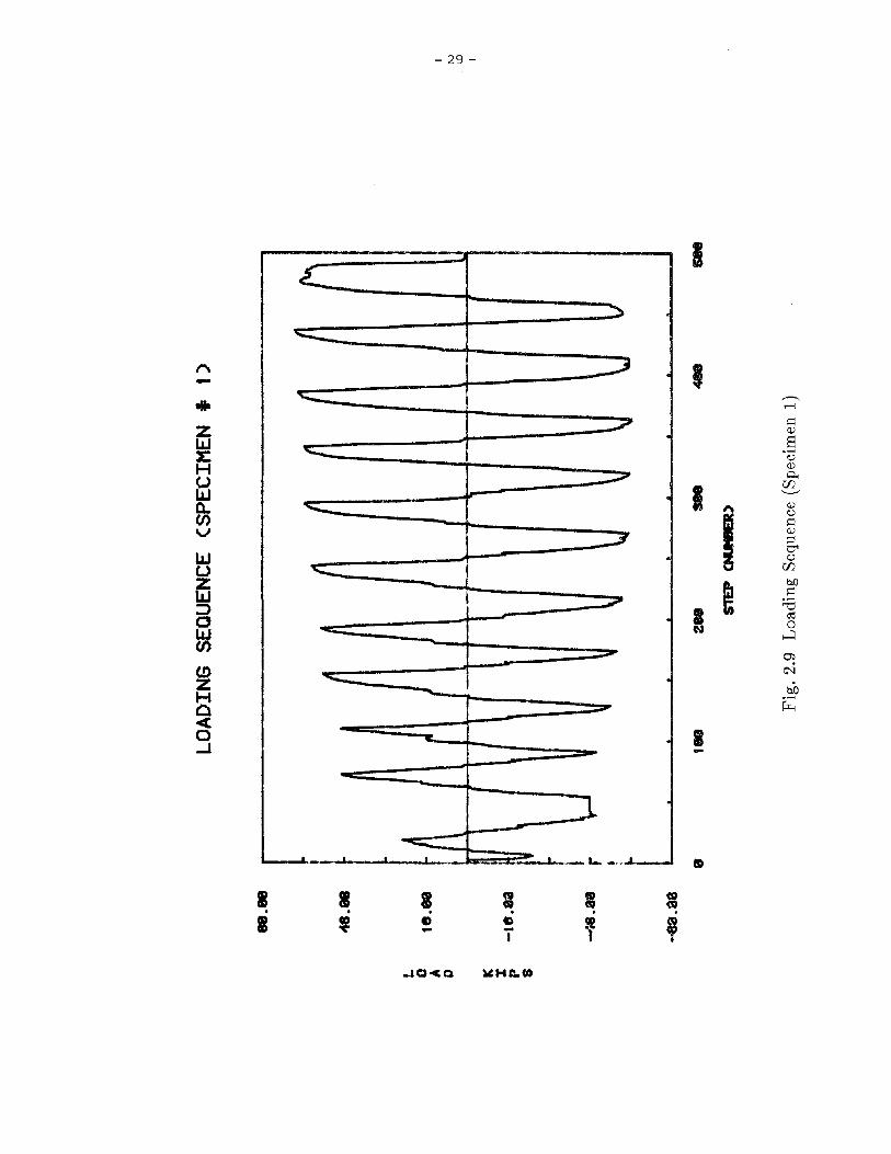
For Specimen 2, the cyclic loading was incrementally increased approximately as for Speci
men 1 until the specimen fractured. Figures 2.9 and 2.10 illustrate the loading histories for
Specimens 1 and 2, respectively. During the entire process, the loading was stopped at
selected points to take readings with a low-speed scanner. A log was maintained during each
test to record critical observations, such as slippage of bolts, flaking of the whitewash, etc.
- 7 -
CHAPTER 3 EXPERIMENTAL RESULTS
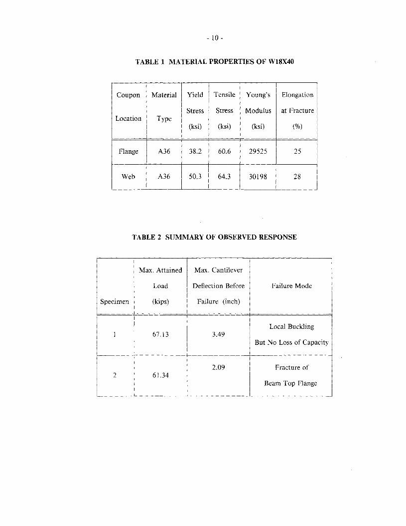
3.1 Material Properties
All steel shapes and plates used to construct the specimens were of ASTM A36. Two
tensile coupon tests were carried out to determine the steel properties using ASTM procedures
[21]. The coupons were taken one each from the flange and web of the W18X40 beam. The
test results are listed in Table 1. The stress-strain curves for the coupon tests were typical of
those for A36 mild steel. The yield plateau before strain hardening occurred at 1.6% and
2.6% of strain for the flange and web coupons, respectively. The actual dimensions of the
beam section were measured and found to be in good agreement with the values in the AISC
Manual [1]. The small differences in size were therefore neglected and the section properties
for W18X40 in the AISC manual were adopted. For Specimen 1, in which two pairs of ribs
were added at the beam-column joint, the section properties of the beam at the juncture were
obtained from the nominal plate dimensions and section properties of a bare W18X40. The
section properties of the W12X133 column stub are given in the AISC Manual, 7th Edition.
3.2 Test Results
For both experiments the load-deformation data were obtained for cyclically applied
loads. The resulting hysteretic loops provide the basic data for determining the behavior of
the specimens. The maximum attained loads, the onset of yielding, and the ultimate inelastic
deformations of the beams were measured in both tests and provided the data for the com
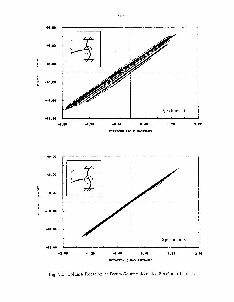
parison of the two specimens. The column rotations at the beam-column joint versus the
applied load are shown in Fig. 3.1 for both experiments. Note that the column behaved elast
ically during both tests. The same column stub could therefore be used for both experiments.
Specimen 1
The relationship between the cantilever tip load and the beam end deflection for Speci
men 1 is shown in Fig. 3.2. The beam responded elastically until the load was slightly beyond

- 8 -
that required to reach the maximum beam bending stress of 36 ksi. The flaking of whitewash
was first observed during the third loading cycle on the beam top flange outside the tips of the
reinforcing rib. As cyclic loading progressed, the corresponding areas enclosed by hysteretic
loops indicate the capacity of a member and its connections to absorb and dissipate energy.
The loops consistently exhibited stable characteristics. During the sixth cycle, no significant
deterioration. of the loop occurred, although local buckling of the bottom flange outside the
reinforcing ribs developed. Subsequently, both the top and bottom flanges had pronounced
local buckling that appeared and disappeared cyclically. However, the beam-column assem
blage maintained load-carrying capacity even when severe local buckling occurred in either of
the flanges.
The web of the beam outside the shear tab buckled during the ninth cycle and was
straightened and buckled cyclically from then on. The hysteretic loop remained stable. Dur
ing the tenth cycle, some LVDTs were removed to prevent damage. The cantilever load was
terminated after pronounced ductility had been observed. The maximum load applied by the
actuator was about 67 kips. A slight reduction of peak load was detected during the last
cycle. No visible slippage of the bolts was detected in the shear tab. Cyclic buckling of the
top or bottom flanges and beam web was observed in the region outside the line connecting
the tips of the top and bottom reinforcing ribs. The buckling of the bottom flange during
advanced stages of testing is shown in Fig. 3.3, and the buckling of the top flange is shown in
Fig. 3.4. The buckling of the beam web is shown in Fig. 3.5. The extent of the yield pattern
at the top continuity plate is shown in Fig. 3.6. The yield pattern in the shear tab is illus
trated in Figs. 3.7 and 3.8.
Specimen 2
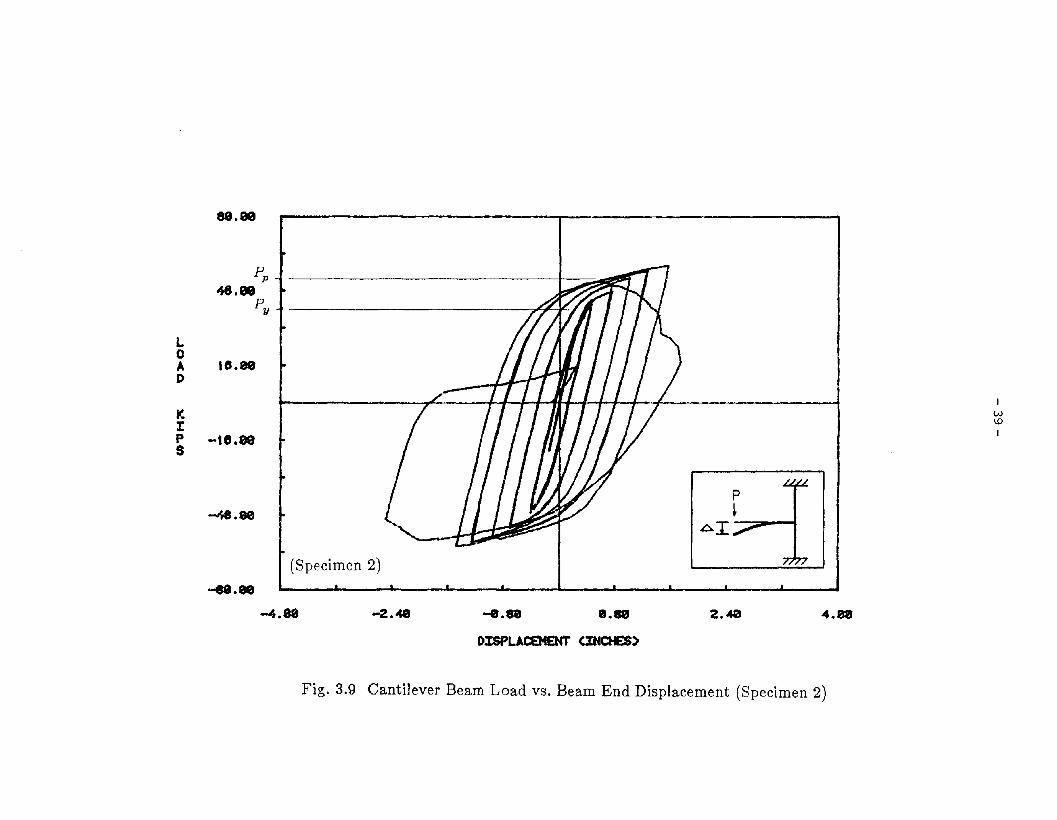
The cantilever tip load versus beam end deflection for Specimen 2 is shown in Fig. 3.9.
The beam again responded elastically up to the load slightly beyond that required to reach the
maximum nominal beam bending stress of 36 ksi. During the second cycle, the whitewash on
the top continuity plate cracked. During the third cycle, a relative movement between the

- 9 -
beam web and the shear tab was observed, causing the bolt to slip. Up to the end of eighth
cycle, extensive slippage of the beam web, flaking of whitewash on both the top and bottom
flanges as well as on the top continuity plate were observed (Fig. 3.10). The whitewash on the
bottom continuity plate did not crack. During the ninth cycle, the beam top flange near the
end of the web-cope cracked beginning at the center of the flange and propagating toward
each side of the flange as the load was increased (Figs. 3.11 and 3.12). At this point, some
clip gages were removed to prevent damage. The beam top flange subsequently fractured and
the beam lost its load-carrying capacity. The crack closed and opened when subjected to sub
sequent cyclic loading. During this test the maximum load attained by the actuator was
about 61 kips. The fractured specimen is shown in Fig. 3.13. Note the severity of the flaking
of whitewash on the top continuity plate. The relative movement between beam web and
shear tab due to the bolt-slippage is shown in Fig. 3.14.
3.3 Summary
Specimen 1 exhibited superb capacities to absorb and dissipate energy. Specimen 2
failed quite abruptly after cracking had begun at the top flange. In general, both specimens
carried load well above the 36 ksi nominal yield strength of the beam. In both experiments,
the hysteretic loops exhibited a considerable amount of strain hardening of the material. The
experimental data are summarized in Table 2.
- 10-
TABLE 1 MATERIAL PROPERTIES OF W18X40
Coupon Material Yield Tensile Young's Elongation
Stress Stress Modulus at FractureLocation Type
(ksi) (ksi) (ksi) (%)
Flange A36 38.2 60.6 29525 25
Web A36 50.3 64.3 30198 28
TABLE 2 SUMMARY OF OBSERVED RESPONSE
Max. Attained Max. Cantilever
Load Deflection Before Failure Mode
Specimen (kips) Failure (inch)
Local Buckling1 67.13 3.49
But No Loss of Capacity
2.09 Fracture of2 61.34
Beam Top Flange

- 11 -
CHAPTER 4 DISCUSSION OF RESULTS
4.1 General
In both experiments, the load-deformation hysteretic loops were stable and remained
remarkably reproducible during consecutive cycles. In Specimen 1, the added web welding
that was capable of developing 22% of the web plastic moment capacity essentially eliminated
bolt slippage. The flanges alone of the W18X40 had 70% of the plastic section modulus of
the entire section. A task force of the SEAOC Seismology Committee, currently working on a
revision of the Blue Book [5], has called for a requirement that the web welding be capable of
developing 20% of the plastic capacity of the girder web if the girder flanges alone have less
than 70% of the plastic section modulus of the entire girder section. Although a requirement
of 20% appears to be justifiable, if the 70% rule is to be used, further investigation seems war
ranted. Excessive web slippage might have contributed to the fracture of the beam top flange
in Specimen 2. Although it would have been beneficial to have had the results of testing a
subassemblage using added web welds but without the top and bottom reinforcing ribs, there
were, unfortunately, insufficient funds to conduct further investigations.
4.2 Analytical Comparisons
In order to gain further insight into the behavior of the two test specimens, some design
parameters are examined below. The section properties and the moment capacities of the
beam sections of both specimen are given in Table 3. The elastic moment capacities, Mvs,
were obtained using a yield strength of 38.2 ksi from the flange coupon test. The moment
capacities, M p s, were obtained from an averaged yield strength of 44.25 ksi from the flange
coupon and the web coupon. For Specimen 1, with rib reinforcement at the built-in end, it is
useful to plot the variation of moment capacity along the axis of the beam (Fig. 4.1). The
applied moment at any section can be determined from statics:

- 12 -
M=P'X
where P is the actuator force and X is the distance from the loading point to the section of
interest. Since the reinforcing ribs increase the section moduli substantially, the critical sec-
tion will occur at the edge of the ribs (Fig. 4.1). Therefore, the elastic yield load, Py , can be
determined:
MyP=
y Lc
where L c is the distance measured from the applied load to the critical section. The plastic
load, Pp , can be determined similarly:
The same approach can be used for Specimen 2. The critical section of this specimen is at
the edges of the column flanges. The results calculated are given in Table 4. To appraise
more accurately the inelastic behavior of the two test beams, the contribution due to the rota-
tion of the column stub must be subtracted from the total displacements, such as those shown
in Fig. 3.2. The applied load versus the beam displacement can thus be plotted for each
specimen. Moreover, both the load and deflection with respect to their corresponding elastic
limits can be normalized. Normalized results for Specimens 1 and 2 are shown in Figs. 4.2
and 4.3, respectively.
The so-called ductility factor, J.L, has been widely used as a measure of the inelastic
behavior of structures. This quantity has been variously defined [23,25], and thus its value
strongly depends on the definition used to derive J.L. When ductility factors are used for pur-
poses of comparison, it is therefore important to consider the definition used to derive J.L, as
well as the loading and the structural parameters involved. While a unique loading sequence
would ideally have been applied to both specimens for the results to be truly comparable, it
was decided that a quantitative as well as qualitative comparison would be valid based on the

- 13 -
loading and structural consistency of the two experiments. Two ductility factors commonly
derived from data such as that plotted in Figs. 4.2 and 4.3 are indicated in Table 4. In
column 5 of this table, the maximum displacements J.ll were measured from the origin to the
peak load, shown as point B in Figs. 4.2 and 4.3, during the last cycle. In column 6, the max
imum displacements J.l2 were measured from the zero load intercepts, shown as point A, to
point B at the peak load. The beam in Specimen 1 was capable of deforming, without
significant loss of capacity, into the inelastic range far beyond the point where the peak load
had occurred. The ductility factors for Specimen 1 are therefore conservative. The active
role of the reinforcing ribs in resisting the load is clear from Figs. 4.4 and 4.5, which show the
strains in the reinforcing ribs during the cyclic loading. Note that the strain gages were
located 1 in. from the top edge of the reinforcing ribs.

- 14 -
TABLE 3 MECHANICAL PROPERTIES OF BEAM SECTIONS
Beam Elastic Plastic Elastic Plastic
Section Modulus Section Modulus Moment Capacity Moment CapacitySection
Sx Cin 3) ZAin 3) My(k-in) Mp(k-in)
W18X40
With 87.0 114.0 3320 5010
Ribs
W18X40 68.4 78.4 2610 3470
TABLE 4 CRITICAL LOADS AND DUCTILITY FACTORS
Critical Elastic Plastic Ductility Ductility
Distance Yield Load Yield Load Factor Factor
Specimen L c (in) Py(kips) Pp(kips) III 112
(1) (2) (3) (4) (5) (6)
1 60.3 43.3 57.7 5.2 10.6
2 65.3 40.0 53.1 4.0 6.5

- 15 -
CHAPTER 5 CONCLUSIONS
5.1 Summary
Structural steel framing is widely used to resist lateral loads in regions of high seismic
risk. Various structural framing systems have been evolved by which the overall stiffness and
strength necessary for seismic resistance are provided. In particular, framed-tube structural
systems consisting of closely spaced columns interconnected by deep spandrel beams have
gained wide acceptance as the perimeter frame for tall buildings. The overall stiffness and
strength of a typical rectangular tubular structure rely on the integrity between the planar
frames in two mutually perpendicular directions. Joints and connections in the corners of
such tubular structures are thus the most critical elements in the system. If wide flange
columns are used in these corners, they must be connected to the spandrel girders in both
strong and weak axes of the columns.
Research to date has provided limited data on the behavior of beam-to-column web
moment connections. Moreover, experimental evidence has shown that some of the connec
tion details commonly used may be dangerous during a major earthquake. This motivated an
alternative concept in which reinforcing ribs are added to the conventional connection. To
investigate the performance of this connection, an experimental program was conducted to
assess the behavior as well as the effectiveness of the web-to-shear tab welding. A compara
tive test on a conventional connection of the best available type was also carried out.
5.2 Conclusions
The following conclusions can be drawn from the experiments:
1. Both specimens carried load well above the 36 ksi nominal yield strength of the
beam, and a considerable amount of strain hardening took place in the post-yield
range.

- 16 -
2. With added reinforcing ribs at the beam-to-column web juncture, the connection
can sustain a large number of loading reversals without failure.
3. With a small amount of web welding, the slippage of the beam web with respect to
the shear tab can essentially be eliminated in the relevant range of loading.
4. For beam flanges with more than 70% of the plastic section modulus of the entire
beam section, some web welding might still be needed to mitigate against the slip
page of the bolts under severe cyclic loading.
5. A good conventional connection detail similar to that used in Specimen 2 may
fracture during a major earthquake.
6. With reinforcing ribs, the critical section of the beam is shifted away from the
heat-affected zones next to the groove welds to the tips of the reinforcings ribs.
7. The concept of adding ribs to conventional beam-to-column web connections
appears to enhance the seismic resistance of buildings. The height of the ribs is
such that they become fireproof after the slab has been cast.
5.3 Future Research Needs
The pilot experimental work described in this paper was aimed at a specific set of
geometric parameters using available materials. A test program covering a wider spectrum of
sections, particularly deeper beams, is needed. The requirements of the beam web welding
for a wide range of beam sections requires further investigation. Alternative details (as shown
in Fig. 5.1) were considered for those beams with either wider or narrower flange widths than
the beams tested. Since full penetration welds project above the top of the continuity plates,
a smooth notch on the bottom of each rib is required as shown in Fig. 5.1. For Specimen 1,
small crescent shape notches were made by grinding to allow placement of continuous welds
along the ribs.

- 17 -
REFERENCES
[1] AISC, "Specifications for the Design, Fabrication and Erection of Structural Steel forBuildings," Manual of Steel Construction, 8th ed., American Institute of Steel Construction, Chicago, 1980.
[2] Uniform Building Code, International Conference of Building Officials, Whittier, California, 1982.
[3] Newmark, N. M., "Design Specifications for Earthquake Resistance," Civil EngineeringFrontiers in Environmental Technology, Dept. of Civil Engineering, University of California, Berkeley, 1971.
[4] Newmark, N. M., Hall, W. J., "Earthquake Spectra and Design," Earthquake Engineering Research Institute, El Cerrito, 1982
[5] SEAOC, Recommended Lateral Force Requirements, Seismology Committee, StructuralEngineering Association of California, San Francisco, 1980.
[6] ATC (Applied Technology Council), Tentative Provisions for the Development ofSeismic Regulations for Buildings, publication ATC 3-06, June, 1978.
[7] Jensen, C. D. et al. Welded Interior Beam-to-Column Connections, American Instituteof Steel Construction, New York, 1959.
[8] Krawinkler, H., Bertero, V. V., and Popov, E. P., "Inelastic Behavior of Steel Beam-toColumn Subassemblages," Report No. UCB/EERC-7I/7, Earthquake EngineeringResearch Center, University of California, Berkeley, 1971.
[9] Popov, E. P. and Stephen, R. M., "Cyclic Loading of Full-Scale Steel Connections,"Report No. UCB/EERC-70-3, Earthquake Engineering Research Center, University ofCalifornia, Berkeley, 1970.
[10] Bertero, V. V., Popov, E. P., and Krawinkler, H., "Further Studies on Seismic Behaviorof Steel Beam-Column Subassemblages," Report No. UCB/EERC-73/27, EarthquakeEngineering Research Center, University of California, Berkeley, 1973.
[11] Popov, E. P. and Stephen, R. M., "Cyclic Loading of Beam-Column Assemblies,"Report No. 84-1, Structural Engineering Laboratory, University of California, Berkeley,1984.
[12] Rogec, J. E., Huang, J. S., and Chen, W. F., "Test of a Fully-Welded Beam-to-ColumnConnection," Publication No. 188, Welding Research Council, 1973.
[13] Chen, W. F. and Patel, K. V., "Static Behavior of Beam-to-Column Moment Connections," Journal ofStructural Division, ASCE, Vol. 107, No. ST9, September 1981.
[14] Slutter, R. G., "Test of Panel Zone Behavior in Beam-Column Connections," ReportNo. 200.81.403.1, Fritz Engineering Laboratory, Lehigh University, Bethlehem,Pennsylvania, 1981.
[15] Popov, E. P. and Pinkney, R. B., "Behavior of Steel Building Connections Subjected toInelastic Strain Reversal," SESM Report No. 67-30, Structures and Materials Research,Dept. of Civil Engineering, University of California, Berkeley, 1967.
[16] Popov, E. P. and Pinkney, R. B., "Behavior of Steel Building Connections Subjected toInelastic Strain Reversal-Experimental Data," SESM Report No.67-31, Structures andMaterials Research, Dept. of Civil Engineering, University of California, Berkeley,1967.
[17] Rentschler, G. P., "Analysis and Design of Steel Beam-to-Column Web Connections,"Ph.D. Dissertation, Dept. of Civil Engineering, Lehigh University, Bethlehem, Pennsylvania, 1979.
[18] Rentschler, G. P., Chen, W. F., and Driscoll, G. c., "Test of Beam-to-Column WebMoment Connections," Journal ofStructural Division, ASCE, Vol. 106, No. ST5, 1980.
[19] Pourbohloul, A., Wang, X., and Driscoll, G. c., "Test on Simulated Beam-to-ColumnWeb Moment Connection Details," Report No. 469.7, Fritz Engineering Laboratory,Lehigh University, Bethlehem, Pennsylvania, 1983.

- 18 -
[20J "AWS Structural Welding Code-Steel," AWS D1.1-80, American Welding Society,Miami, 1980.
[21] American Society for Testing and Materials, Standard Methods of Tension Testing ofMetallic Materials, ASTM Designation E8-79, Philadelphia, Pennsylvania, 1980.
[22] Popov, E. P., "Seismic Moment Connections for Moment-Resisting Steel Frames,"Report No. UBC/EERC/83-02, Earthquake Engineering Research Center, University ofCalifornia, Berkeley, 1983.
[23] Popov, E. P. and Pinkney, R. B., "Cyclic Yield Reversal in Steel Building Connections," Journal of the Structural Division, ASCE, Vol. 95, No. ST3, 1969.
[24J Wang, c., "Structural System-Getty Plaza Tower," Engineering Journal, AmericanInstitute of Steel Construction, Chicago, Vol. 21, No.1, 1984.
[25J Galambos, T. V., "Deformation and Energy Absorption Capacity of Steel Structures inthe Inelastic Range," Bulletin No.8, American Iron and Steel Institute, New York,1968.
[26J Lee, S.-J. and Lu, L.-W., "Cyclic Tests of Full-Scale Composite Beam-to-ColumnJoints," Report 467.6, Fritz Engineering Laboratory; also in Proceedings, U.S.-JapanCooperative Research Program, Hawaii, June 1985.

(A) BEAM-TO-COLUMN FLANGE
Fig. 1.1 Steel Beam-to-Column Moment Connections
j IIIIIiIIIIIiIIIIIIIIr---.. II
~ -~u
-0
0
0
0'-;;: I)
~lJ-
II\IIIIIIIIIII
( B ) BEAM-TO-COLUMN WEB IIIIII
If-'~
I

- 20 -
Fig. 1.2 General View of New Design

Sf 4 ~ II
TT ~
II '-.01:::==11== -,
r I
+ r~"W12X133~ II
II ::::II '<;j-
W18X40~ II (Y)"~II '-.0
1"\ Il--~- ....-..l---I- - (\J\.:: 1
=0
0- - -
0
0 ........r 1
~h"¢-...
...... - (Y)"'-.0I
I---- ....II (\JIIIIIIII
;::==rl===~
II I..[)II ,
Fig. 2.1 Subassemblage of Beam-to-Column Web Moment Connection
CL
IN~
I
- 22 -
o !I 0 ! ! I ! 0 !I I - --- --II !! I I i II I l! I__-'-_~"'" _~ ..J_L LJ ..__ L. _-L. __
-=fTr:t----------------Tl-------------------lr--------------:t--rr~- - ---0' 'I' I' III' , " It" II 0 000
1=1Q)
S'0
Q)
0..lf1......0~
1=1Q)
SQ)
bO1=1C'OI-<l-<
" -<"6) bO
I1=1
:;:;1=1;:j
\.0 0~
C'!C'l
.~~
I
~~,-,v-A-:-S-=-9---'-G---.r-,~--/I'-V/{-r£-;:9.----,-=G;----,~

o SECTION
I 3" I~
i i
I!'JW
I
® SECTION
3/8) I) (T YP.
4-1"$ A32S-X BOLTS
~ 1/4 ROOT OPN1/2X2X9 TYP 3/aXl tj.u. <
(Q TYP
~
(")
~
(")
~
(")
W12X133
®
\< II J I 3/a" THK
3/4 THK. CON. PL.
5/8 THK. CON. PL.
~
Fig. 2.3 Connection Detail (Specimen 1)
IN~
ITYP
1/4 ROOT OPN3/aXl B. U. <r~ TYP
A325-X BOLTS/4-1"<1'
o SECTION
o SECTION
== L:= ~::::~l=-==
W18X40)
W12X133
~
5/8 THK. CON. PL.
3/4 THK. CON. PL.
~
Lg
1/4
3/8ITHK
11/4 " RAD. ~
Fig. 2.4 Connection Detail (Specimen 2)

- 25 -

- 26-
- 27 -
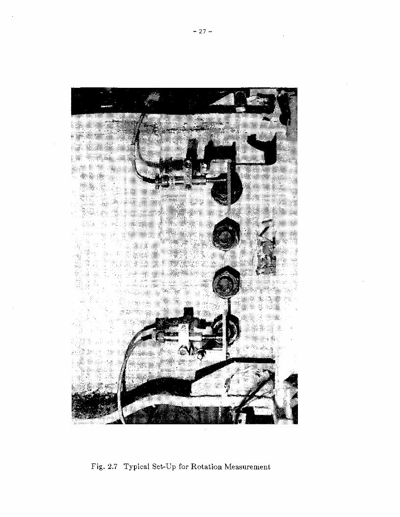
Fig. 2.7 Typical Set-Up for Rotation Measurement

- 28-
-•ZlJJJ:HUlJJQ.(J)v
lJJUZW:::>olJJ(J)
CDZHo<o..J
- 29-
L~
""""--
~
~
-" .~
..;;,;;;;;' ........-..
..-:'
""'-
...,.,
........... --,
.J.~. . . I _L.._.~
,,---.,.-i
~Q.)
.5<:..lQ.)
0..
Iif]'---'
"Q.)
!<:..l~Q.)
~0"Q.)
u if]
e b.O~
I:.s
(;\j0
....::l
~
C'l
b.O.-~
I
I.I
I., I.C)-
I.C)
i=.

"C\I
•ZW:t:H
fdQ.CJ)v
WUZW:;:)o~CDZHo<o-J
- 30 -
·
~~ ·
~ ·J'
'-.-ii'
"""'"--..-'
-'.
::::::""~
---- --'"
""'- --• ~ • .
I.---...C'l
~(1)
S'0
(1)
n 0..
Iif2'---"
(1)
I<.l>:1(1)
;:;
~0'(1)
if2
bO~
:.aro0~
0,....,
I C'l- bO.-~
CD
I.I
I.C)-
.JO-cO
I.C)-t
{3., =.;
- 31-
88 .•
Specimen I
JMS ••
L0A te.•D
KIP -IfL.S
-88.•
ea .•
-2.• -1.28 8.48
ROTATI:ON cte-s RADIANS)
1.28 2 .•
JMS ••
L0It. te .•D
II:IP -te .•s
~.•"'.99
Specimen 2
-2.88 -1.28 -e.48 8.48 1.28 2 .•
ROTATION cte-s RADIANS)
Fig. 3.1 Column Rotation at Beam-Column Joint for Specimen 1 and 2

89.08
Pp
48••Py
L0 te.""AD
t<I -ta.etaps
-J,s.a0
-sa.00
(Specimen 1)
p
+AI
IwtvI
~.99 -2.48 -0.8e e.• 2.48 4.08
OISPLAca4ENT CINCHES)
Fig. 3.2 Cantilever Beam Load vs. Beam End Displacement (Specimen 1)
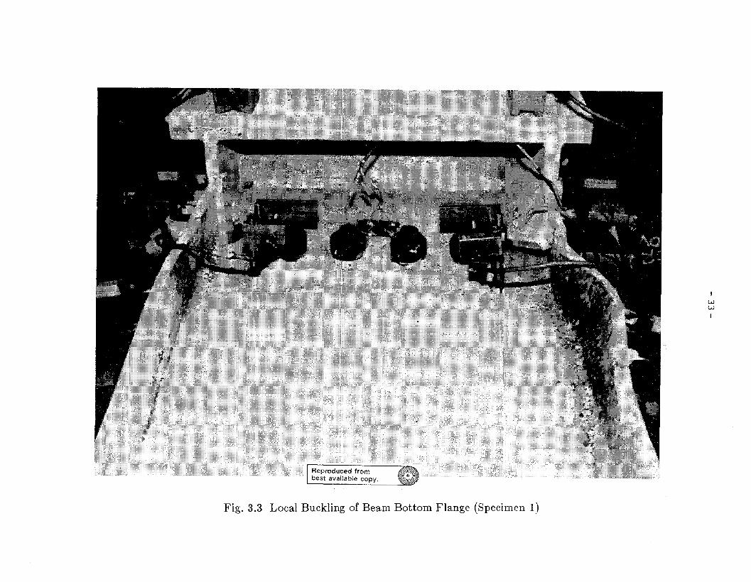
Fig. 3.3 Local Buckling of Beam Bottom Flange (Specimen 1)
IWW
I

Fig. 3.4 Local Buckling of Beam Top Flange (Specimen 1)
IWII:>I

Fig. 3.5 Local Buckling of Beam Web (Specimen 1)
IWlJ1
I

Fig. 3.6 Yield Pattern at Top Continuity Plate (Specimen 1)
IW0'1
I

- 37-
. ii
., ...·ri·.:.,'
Fig. 3.7 Yield Pattern at Beam Web (Specimen 1)
i.1'"Eg-
E"- .."0::0.. CllCJ:=::3 Cll"0>o Cll
~Ujcell
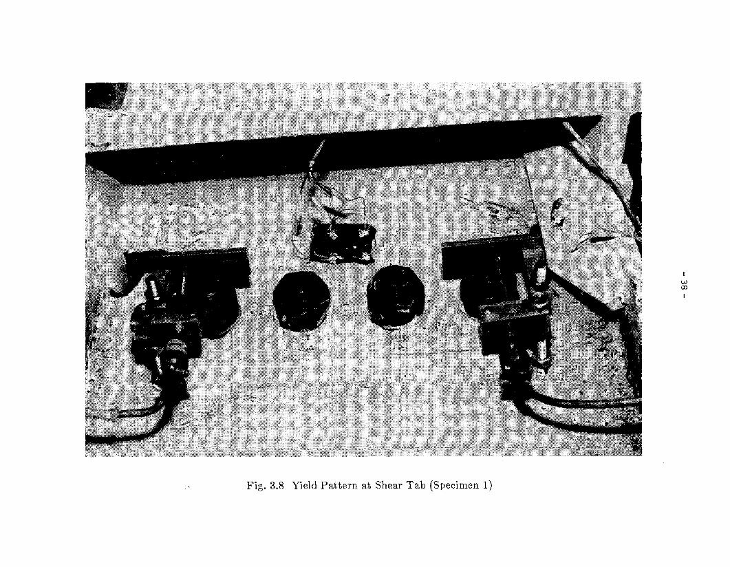
Fig. 3.8 Yield Pattern at Shear Tab (Specimen 1)
IW<XlI
88.00
pt
AI~.ee
Pp
48.00Py
l0A te.eeD
~ -10.88 I ./-- Tl//II///7 II
T 17" TIT/ w\DI
(Specimen 2)
-ea.•-4.88 -2.48 -8.88 8.88 2.<40 4.88
l>:rsPLACEHENT aNa£$)
Fig. 3.9 Cantilever Beam Load vs. Beam End Displacement (Specimen 2)

Fig. 3.10 Flaking of Whitewash on Bottom Flange (Specimen 2)
I~oI

Fig. 3.11 Crack Initiation on Beam Top Flange (Specimen 2)
I0I::l-'I
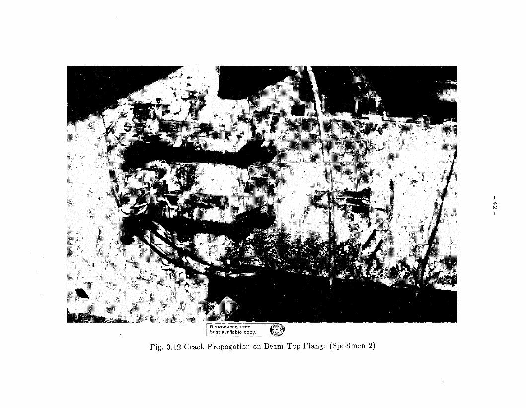
Fig. 3.12 Crack Propagation on Beam Top Flange (Specimen 2)
I~l\.)
I

- 43-
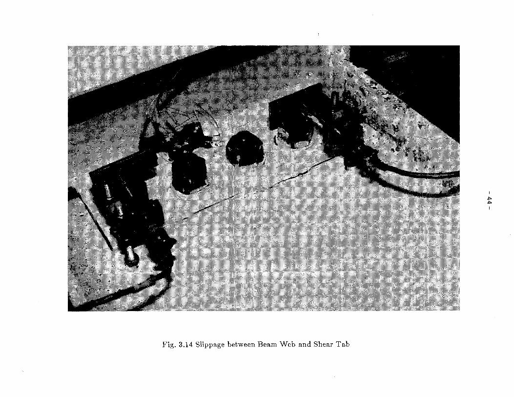
Fig. 3.14 Slippage between Beam Web and Shear Tab
I~~
I

I~VI
I
6~16"
_.-.~ ..-.- ..
_._-_._._. pp. X
----- P • Xy
Mp
M~
~~~~~~~~~~~~~~:=:;;;;:::::~;:~:~~::::::=-------1<"""""-''# !---______--1
p ~
~ l~
1,.....,
~. 1--,.--J
0"\.
0I :;-X0::r
"-0
1)1.-..- I.. fIL--
L.-
I--t\
5/ Sl:X6" ~ 't~
Fig. 4.1 Beam Moment Capacity and Applied Moment
KIp
/ -1.20KIp
PPlJ
NoRMALIZED
LoAD
2.00
1.20
0.40
-0.40
"-' f.l2 I -.I
B
AI
p~
//
I~mI
NORMALIZED DISPLACEMENT (IN/IN)
-2.00
-10.00 -6.00
AA,l
-2.00 2.00 6.00 10.00
Fig. 4.2 Normalized Load vs. Beam Deflection Curve (Specimen 1)

-0.40
KIp/ -1.20Kor.L
P
-2.00
-10.00
NORMALIZED DISPLACEMENT (IN/IN)
PPy
NoRMALIZED
LoAD
2.00
1.20
0.40
AI
p~
-6.00
1:l1:l 71
-2.00
112----1Pl---J B
2.00 6.00 10.00
I.I:>--J
I
Fig. 4.3 Normalized Load vs. Beam Deflection Curve (Specimen 2)
88.88
.IrS.ee
-MI.rae
-80.03
L.0A 16.00D
~ -tUG l #ffIIItI
I.Po
S
ex:>I
-~.a0 -1.21 -8.48 I." 1.28 2.88
STRAIN (te-S)
Fig. 4.4 Strain in Top Reinforcing Rib (Specimen 1)

88.88
48.88
-48.•
-88.88
L0Ate.•D
Yo ~ ~~~\\\ II
! -t8.88 I Rt I II::>~
I
-1.88 -a.e' -8.28 8.28 8.88 1.88
STRAIN (t8-3)
Fig. 4.5 Strain in Bottom Reinforcing Rib (Specimen 1)
ILnoI
...' I) <TYP.
r TYP•
o SECTION
MIN.
) I) qyP.
(A) SECT I ON
~
~
Fig. 5.1 Alternative Reinforcing Rib Details

- 51-
EARTHQUAKE ENGINEERING RESEARCH CENTER REPORTS
NOTE: Numbers in parentheses are Accession Numbers assigned by the National Technical Information Service; these arefollowed by a price code. Copies of the reports may be ordered from the National Technical Information service, 5285Port Royal Road, Springfield, Virginia, 22161. Accession Numbers should be quoted on orders for reports (PB --- ---Iand remittance must accompany each order. Reports without this information were not available at time of printing.The complete list of EERC reports (from EERC 67-1) is available upon request from the Earthquake Engineering ResearchCenter, university of California, Berkeley, 47th Street and Hoffman Boulevard, Richmond, California 94804.
UCB/EERC-79/01 "Hysteret:Lc Behavior of Lightweight Reinforced COncrete Beam-COlumn Subassemblages," by B. Forzani,E.P. Popov and V.V. Bertero - April 1979(PB 298 267)A06
UCB/EERC-79/02 "The Development of a Mathematical Model to Predict the Flexural Response of Reinforced Concrete Beamsto Cyclic wads, Using System Identification," by J. Stanton & H. McNiven - Jan. 1979(PB 295 875)AlO
UCB/EERC-79/03 "Linear and Nonlinear EarthqUake Response of Simple Torsionally Coupled Systems," by C.L. Kan andA.K. Chopra - Feb. 1979(PB 298 262)A06
UC8/EERC-79/04 "A Mathematical I-bdel of Masonry for predicting its Linear Seismic Response Characteristics," byY. Mengi and H.D. McNiven - Feb. 1979(PB 298 266)A06
UCB/EERC-79/05 "Mechanical Behavior of Lightweight Concrete Confined by Different Types of Lateral Reinforcement,"by M.A. Manrique, V.V. Bertero and E.P. Popov - May 1979(PB 301 114)A06
UCB/EERC-79/06 "Static Tilt Tests of a Tall Cylindrical Liquid Storage Tank," by R.W. Clough and A. Niwa - Feb. 1979(PB 301 167) A06
UCB/EERC-79/07 "The Design of Steel Energy Absorbing Restrainers and '!heir Incorporation into Nuclear Power Plantsfor Enhanced Safety: Volume 1 - Summary Report," by·P.N. Spencer, V.F. zackay, and E.R. Parker Feb. 1979{UCB/EERC-79/07)A09
UCB/EERC-79/08 "The Design of Steel Energy Absorbing Restrainers and '!heir Incorporation into Nuclear Power Plantsfor Enhanced Safety: Volume 2 - '!he Development of Analyses for Reactor System Piping, ....Simple Systems"by M.C. Lee, J. Penzien, A.K. Chopra and K, Suzuki "COmplex Systems" by G.H. Powell, E.L. Wilson,R.W. Clough and D.G. Row - Feb. 1979(UCB/EERC-79/08)A10
UCB/EERC-79/09 "The Design of Steel Energy Absorbing Restrainers and Their Incorporation into Nuclear PCMer Plantsfor Enhanced Safety: Volume 3 - Evaluation of Commercial Steels," by W.S. Owen, R.M.N. Pelloux,R.O. Ritchie, M. Faral, T. Ohhashi, J. Toplosky, S.J. Hartman, V.F. Zackay and E.R. Parker -Feb. 1979{UCB/EERC-79/09)A04
UCB/EERC-79/10 "The Design of Steel Energy Absorbing Restrainers and Their Incorporation into Nuclear Power Plantsfor Enhanced Safety: Volume 4 - A Review of Energy-Absorbing Devices," by J .M. Kelly andM.S. Skinner - Feb. 1979(UCB/EERC-79/10)A04
UCB/EERC-79/11 "Conservatism In Summation Rules for Closely Spaced Iotodes," by J.M. Kelly and J.L. Sackman - May1979(PB 301 328)A03
UCB/EERC-79/12 "cyclic Loading Tests of Masonry Single Piers; Volume 3 - Height to Width Ratio of 0.5," byP.A. Hidalgo, R.L. Mayes, H.D. McNiven and R.W. Clough - May 1979(PB 301 321)A08
UCB/EERe-79/13 "Cyclic Behavior of Dense Course-Grained Materials in Relation to the Seismic Stability of Dams," byN.G. Banerjee, H.B. Seed and C.K. Chan - June 1979(P8 301 373)A13
UCB/EERC-79/l4 "Seismic Behavior of Reinforced COncrete Interior Beam-Column Subassemblages," by S. Viwathanatepa,E.P. Popov and V.V. Bertero - June 1979(PB 301 326)AlO
UCB/£ERe-79/l5 "optimal Design of Localized Nonlinear Systems with Dual Performance. Criteria Under EarthquakeExcitations," by M.A. Bhatti - July 1979(PB 80 167 109)A06
UCB/EERC-79/l6 "OPTDYN - A General Purpose Optimization Program for Problems wi th or wi. thout Dynamic Cons traints ,"by M.A. Bhatti, E. Polak and K.S. Pister - July 1979(PB 80 167 091)A05
UCB/EERC-79/17 "ANSR-II, Analysis of Nonlinear Structural Response, Users Manual," by D.P. I-bndkar and G.H. powellJuly 1979(PB 80 113 301)A05
UCB/EERC-79/l8 "Soil Structure Interaction in Different Seismic Environments," A. Gomez-Masso, J. Lysmer, J.-C. Olenand H.B. Seed - August 1979(PB 80 101 520)A04
UCB/EERC-79/l9 "ARMA Models for Earthquake Ground Motions," by M.K. Chang, J.W. Kwiatkowski, R.F. Nau, R.M. Oliverand K.S. Pister - July 1979{PB 301 166}A05
UCB/EERC-79/20 "Hysteretic Behavior of Reinforced Concrete Structural Walls," by J. M. Vallenas, V. V. Bertero andE.P. Popov - August 1979(PB 80 165 905}Al2
UCB/EERC-79/21 "Studies on High-Frequency Vibrations of Buildings - 1: '!he Column Effect," by J. Lubliner - August 1979{PB 80 158 553)A03
UCB/EERC-79/22 "Effects of Generalized Loadings on Bond Reinforcing Bars Embedded in COnfined COncrete Blocks," byS. Viwathanatepa, E.P. Popov and V.V. Bertero - August 1979(PB 81 124 018}A14
UCB/EERC-79/23 "Shaking Table Study of Single-Story Masonry Houses, Volume 1: Test Structures 1 and 2, " by P. GUlkan,R.L. Mayes and R.W. Clough - Sept. 1979 (HUD-OOO 1763)A12
UCB/EERC-79/24 "Shaking Table Study of Single-Story Masonry Houses, Volume 2 : Test St:ructures 3 and 4, " by P. GUlkan,R.L. Mayes and R.W. Clough - Sept. 1979 (HUD-OOO 1836)A12
UCB/EERC-79/25 "Shaking Table Study of Single-Story Masonry Houses, Volume 3: Summary, Conclusions and Re=mmendations,"by R.W. Clough, R.L. Mayes and P. Gulkan - Sept. 1979 (HUD-OOO 1837)A06

- 52-
UCB/EERC-79/26 "Re=lMIendations tor a u.s. -Japan Cooperative Research Program Utilizing Large-Scale Testing Facilities ,"by U.S.-Japan Planning Group - Sept. 1979(PB 301 407)A06
UCJ3/EERC-79/27 "Earthquake-Induced Liquefaction Near Lake Amatitlan, Guatemala," by H.B. Seed, 1. Arango, C.K. Olan,A. Gomez-Masso and R. Grant de Ascoli - Sept. 1979(NUREG-CRl341)A03
UCJ3/EERC-79/28 "Infill Panels: 'Iheir Influence on Seismic Response of Buildings," by J.W. Axley and V. V. BerteroSept. 1979(PB BO 163 371)AlO
UCB/EERC-79/29 "3D Truss Bar Element (Type 1) for the ANSR-II Program," by D.P. Mondl<ar and G.H. Powell - Nov. 1979(PB BO 169 709) A02
UCI3/EERC-79/30 "20 Beam-Column Element (Type 5.- Parallel Element 'Iheory) for the ANSR-II Program," by D.G. Ibw,G.H. Powell and D.P. Mondl<ar - Dec. 1979(PB BO 167 224)A03
UCI3/EERC-79/31 "3D Beam-Column Element (Type 2 - Parallel Element 'Iheory) for the ANSR-II Program," by A. Riahi,G.H. Powell and D.P. Mbndkar - Dec. 1979(PB BO 167 216)A03
UCB/EERC-79/32 "On Response of Structures to Stationary Excitation," by A. Der Kiureghian - Dec. 1979(PB B0166 929)A03
UCB/EERC-79/33 "Undistumed Sampling and Cyclic Load Testing of Sands," by S. Singh, H.B. Seed and C.K. OlanDec. 1979(ADA OB7 29B)A07
UCB/EERC-79/34 "Interaction Effects of Simultaneous 'Ibrsional and Compressional Cyclic Loading of Sand," byP.M. Griffin and W.N. Houston - Dec. 1979{ADA 092 352)Al5
UCB/EERC-BO/Ol "Earthquake Response of Concrete Gravity Dams Including Hydrodynamic and Foundation InteractionEffects," by A.K. Chopra. P. Chakrabarti and S. Gupta - Jan. 19BO(AD-AOB7297)AlO
UCB/EERC-80/02 "Rocking Response of Rigid Blocks to EarthqUakes," by C.S. 'lim, A.K. Chopra and J. penzien - Jan. 1980(PB80 166 002)A04
UCEi/EERC-80/03 "Optimum Inelastic Design of Seismic-Resistant Reinforced Concrete Frame Structures," by S.W. zagajeskiand V.V. Bertero - Jan. 19BO{PB80 164 635)A06
UCB/EERC-80/04 "Effects of Amount and Arrangement of Wall-Panel Reinforcement on Hysteretic Behavior of ReinforcedConcrete Walls," by R. Iliya and V.V. Bertero - Feb. 1980{PBBl 122 525)A09
UCB/EERC-80/05 "Shaking Table Research on Concrete Dam Models," by A. Niwa and R.W. Clough - Sept. 19BO(PBBl122 36B)A06
UCB/EERC-80/06 "The Design of Steel Energy-Absorbing Restrainers and their Incorporation into Nuclear Power Plants forEnhanced Safety (VoIlA): Piping with Energy Absorbing Restrainers: Parameter Study on Small Systems,"by G.H. Powell, C. Oughourlian and J. Simons - June 1980
UCB/EERC-80/07 "Inelastic Torsional Response of Structures Subjected to Earthquake Ground Motions," by 'l. YamazakiApril 1980(PBBl 122 327)A08
UCB/EERC-80/0S "Study of X-Braced Steel Frame Structures Under Earthquake Simulation," by Y. Ghanaat - April 1980{PB8l 122 335)All
UCB/EERC-80/09 "Hybrid Mbdelling of Soil-Structure Interaction," by S. Gupta, T.W. Lin, J. Penzien and C.S. YehMay 1980(PBBl 122 319)A07
UCB/EERC-80/10 "General Applicability of a Nonlinear Model of a One Story Steel Frame," by B.I. Sveinsson andH.D. McNiven - May 19BO(PB81 124 877)A06
UCB/EERC-80/11 "A Green-Function Method for Wave Interaction with a Submerged Body," by W. Kioka - April 1980(PBSI 122 269)A07
UCB/EERC-80/12 "Hydrodynamic Pressure and Added ~1ass for Axisymmetric Bodies," by F. Nilrat - May 1980(PBBl 122 343)AOB
UCB/EERC-80/13 "Treatment of Non-Linear Drag Forces Acting on Offshore Platforms," by B.V. Dao and J. PenzienMay 1980{PBBl 153 413)A07
UCB/EERC-80/l4 "2D Plane/Axisymmetric Solid Element (Type 3 - Elastic or Elastic-Perfectly Plastic) for the ANSR-IIProgram," by D.P. Mondkar and G.H. Powell - July 1980(PBBl 122 350)A03
UCB/EERC-80/15 "A Response Spectrum Method for Random Vibrations," by A. Der Kiureghian - June 1980 (PB81122 301) A03
UCB/EERC-80/16 "Cyclic Inelastic Buckling of Tubular Steel Braces," by V.A. Zayas, E.P. Popov and S.A. MahinJune 1980(PB81 124 885)AlO
UCB/EERC-80/17 "Dynamic Response of Simple Arch Dams InclUding Hydrodynamic Interaction," by C.S. Porter andA.K. Chopra - July 1980(PB81 124 000)A13
UCB/EERC-80/18 "Experimental Testing of a Friction Damped Aseismic Base Isolation System with Fail-SafeCharacteristics," by J.M. Kelly, K.E. Beucke and M.S. Skinner - July 1980{PB81 148 595)A04
UCB/EERC-80/l9 "The Design of Steel Energy-Absorbing Restrainers and their Incorporation into Nuclear Power Plants forEnhanced Safety (Vol IB): Stochastic Seismic Analyses of Nuclear Power plant Structures and PipingSystems Subjected to Multiple Support Excitations," by M.C. Lee and J. Penzien - June 1980
UCB/EERC-80/20 "The Design of Steel Energy-Absorbing Restrainers and their Incorporation into Nuclear Power Plantsfor Enhanced Safety (Vol lC): Numerical Method for Dynamic Substructure Analysis," by J.M. Dickensand E.L. Wilson - June 1980
UCB/EERC-80/21 "The Design of Steel Energy-Absorbing Restrainers and their Incorporation into Nuclear Power Plantsfor Enhanced Safety (Vol 2): Development and Testing of Restraints for Nuclear Piping Systems," byJ.M. Kelly and M.S. Skinner - June 1980
UCB/EERC-80/22 "3D Solid Element (Type 4-Elastic or Elastic-Perfectly-Plastic) for,the ANSR-II Program," byD.P. Mondkar and G.H. Powell - July 1980(PB8l 123 242)A03
UCB/EERC-80/23 "Gap-Friction Element (Type 5) for the ANSR-II Program," by D.P. Mondkar and G.H. Powell - July 1980(PB81 122 285)A03

UCB/EERC-80/24
UCB/EERC-80/25
UCB/EERC-80/26
UCB/EERC-80/27
UCB/EERC-80/28
UCB/EERC-80/29
UCB/EERC-80/30
UCB/EERC-80/3l
UCB/EERC-80/32
UCB/EERC-80/33
UCB/EERC-80/34
UC3/EERC-80/35
UCB/EERC-80/36
UCB/EERC-80,l37
UCB/EERC-80/38
UCB/EERC-80/39
UCB/EERC-80/40
UCB/EERC-80/4l
UCB/EERC-80/42
UCB/EERC-80/43
UCB/EERC-81/01
UCB/EERC-81/02
UCB/EERC-81/03
UCB/EERC-81/04
UCB/EERC-81/05
UCB/EERC-81/06
UCB/EERC-8l/07
UCB/EERC-8l/08
UCB/EERC-81/09
- 53 -
"U-Bar Restraint Element (Type 11) for the ANSR-II Program," by C. Oughourlian and G.H. PowellJuly 1980(PB81 122 293)A03
"Testing of a Natural Rubber Base Isolation System by an Explosively Simulated Earthquake," byJ.M. Kelly - August 1980(PB81 201 360)A04
"Input Identification from Structural Vibrational Response," by Y. Hu - August 1980(PB8l 152 308)A05
"Cyclic Inelastic Behavior of Steel offshore Structures," by V.A. Zayas, S.A. Mahin and E.P. PopovAugust 1980(PB8l 196 IBOlA15
"Shaking Table Testing of a Reinforced Concrete Frame with Biaxial Response," by M.G. OlivaOctober 1980(PB81 154 304)AIO
"Dynamic Properties of a Twelve-Story Prefabricated Panel Building," by J.G. Bouwkamp, J.P. Kolleggerand R.M. Stephen - October 1980(PB82 117 128)A06
"Dynamic Properties of an Eight-Story Prefabricated Panel Building," by J.G. Bouwkamp, J.P. Kolleqgerand R.M. Stephen - October 1980(PB8l 200 3l3)A05
"Predictive Dynamic Response of Panel Type Structures Under Earthquakes," by J.P. Kollegger andJ.G. Bouwkamp - October 1980(PB8l 152 316)A04
"The Design of Steel Energy-Absorbing .Restrainers and their Incorporation into Nuclear Power Plantsfor Enhanced Safety (Vol 3): Testing of Commercial Steels in Low-Cycle Torsional Fatigue," byP. ~~~nc~r, E.R. parker, E. Jongewaard and M. Drory
"The Design of Steel Energy-Absorbing Restrainers and their Incorporation into Nuclear P"",er Plantsfor Enhanced Safety (Vol 4): Shaking Table Tests of Piping Systems with Energy-Absorbing Restrainers,"by S.F. Stiemer and W.G. Godden - Sept. 1980
"The Design of Steel Energy-Absorbing Restrainers and their Incorporation into Nuclear Power Plantsfor Enhanced Safety (Vol 5): Summary Report," by P. Spencer
"Experimental Testing of an Energy-Absorbing Base Isolation System," by J.M. Kelly, M.S. Skinner andK.E. Beucke - October 1980 (PB81· 154 072)A04
"Simulating and Analyzing Artificial Non-Stationary Earthquake Ground Motions," by R.F. Nau, R.M. Oliverand K.S. Pister - October 1980(PB81 153 397)A04
"Earthquake Engineering at Berkeley - 1980," - Sept. 1980(PB81 205 874)A09
"Inelastic Seismic Analysis of Large Panel Buildings," by V. Schricker and G.H. Powell - Sept. 1980(PB81 154 338)Al3
"Dynamic Response of Embankment, concrete-Gravity and Arch Dams Including Hydrodynamic Interaction,"by J.F. Hall and A.K. Chopra - October 1980(PB81 152 324)All
"Inelastic Buckling· of Steel Struts Under Cyclic LOad Reversal," by R.G. Black, Ii.A. wenger andE.P. Popov - October 1980(PB81 154 312)A08
"Influence of Site Characteristics on Building Damage During the October 3" 1974 Lima Earthquake," byP. Repetto, I. Arango and H.B. Seed - Sept. 1980(PB81 161 739)A05
"Evaluation of a Shaking Table Test Program on Response Behavior of a Two Story Reinforced ConcreteFrame," by J.M. Blondet, R.W. Clough and S.A. Mahin
"Modelling of SOil-Structure Interaction by Finite and Infinite Elements," by F. Medina December 1980(PB81 229 270)A04
"Control of Seismic Response of Piping Systems and Other Structures by Base Isolation," edited by J.M.Kelly - January 1981 (PB81 200 735)A05
"OPTNSR - An Interactive Software System for Optimal Design of Statically and Dynamically LoadedStructures with Nonlinear Response," by M.A. Bhatti, V. Ciampi and K.S. Pister - January 1981(PB81 218 85l)A09
"Analysis of Local Variations in Free Field Seismic Ground Motions," by J.-c. Chen, J. Lysmer and H.B.Seed - January 1981 (AD-A099508)A13
"Inelastic Structural Modeling of Braced Offshore Platforms for seismic Loading," by V.A. Zayas,P.-S.B. Shing, S.A. Mahin and E.P. Popov - January 1981(PB82 138 777)A07
"Dynamic Response of Light Equipment in Structures," by A. Der Kiureghian, J.L. Sackman and B. Nouromid - April 1981 (PB81 218 497)A04
"Preliminary Experimental Investigation of a Broad Base Liquid Storage Tank," by J.G. Bouwkamp, J.P.Kollegger and R.M. Stephen - May 1981(PB82 140 385)A03
"The Seismic Resistant Design of Reinforced Concrete Coupled Structural Walls," by A.E. Aktan and V.V.Bertero - June 1981(PB82 113 358)All
"The Undrained Shearing Resistance of Cohesive Soils at Large Deformations," by M.R. Pyles and H.B.Seed - August 1981
"Experimental Behavior of a Spatial Piping System with Steel Energy,.Absorbers Subjected to a SimulatedDifferential Seismic Input," by S.F. Stiemer, W.G. Godden and J.M. Kelly - July 1981

UCB/EERC-81/10
UCB/EERC-81/ll
UCB/EERC-81/12
UCB/EERC-81/13
UCB/EERC-81/14
UCB/EERC-8l/1S
UCB/EERC-8l/16
UCB/EERC-8l/l7
UCB/EERC-81/18
UCB/EERC-81/19
UCB/EERC-8l/20
UCB!EERC-82/01
UCB/EERC-82/02
UCB/EERC-82/03
UCB/EERC-82/04
UCB/EERC-62/0S
UCB!EERC-62/06
UCB/EERC-82/07
UCB/EERC-82/08
UCB/EERC-82/09
UCB/EERC-82/10
UCB/EERC-82/11
UCB/EERC-82/l2
UCB/EERC-82/13
UCB/EERC-82/l4
UCB/EERC-82/l5
UCB/EERC-82/l6
UCB/EERC-82/17
- 54-
"Evaluation of Seismic Design Provisions for Masonry in the United States," by B.I. Sveinsson, R.L.Mayes and H.D. McNiven - August 1981 (PB82 166 075lA08
"Two-Dimensional Hybrid Modelling of Soil-Structure Interaction," by T.-J. Tzong, S. Gupta and J.Penzien - August 1981(PB82 142 118lA04
·Studies on Effects of Infills in Seismic Resistant RIC Construction,· by S. Brokken and V.V. Bertero September 1981 (PB82 166 1901A09
·Linear Models te Predict the Nonlinear Seismic Behavior of a One-Story Steel Frame,· by H. Valdimarsson,A.H. Shah and H.D. HcNiven - September 1981(PBB2 138 793)A07
"TLUSH: A Computer Program for the Three-Dimensional Dynamic Analysis of Earth Dams," by T. Kagawa,L.R. Mejia, H.B. Seed and J. Lysmer - September 1981(PB82 139 940)A06
"Three Dimensional Dynamic Response Analysis of Earth Dams," by L.H. Mejia and H.B. Seed - September 1981(PS82 137 274)A12
·Experimental Study of Lead and Elastomeric Dampers for Base Isolation Systems," by J.H. Kelly andS.B. Hodder - October 1981 (PS82 166 182)A05
"The Influence of Base Isolation on the Seismic Response of Light Secondary Equipment," by J.M. Kelly _April 1981 (PB82 255 266)A04
"Studies on Evaluation of Shaking Table Response Analysis Procedures," by J. Marcial Blondet - November1981 (PB82 197 278lAlO
"DELIOHT.STRUCT: A Computer-Aided Design Environment for Structural Engineering," by R.J. Balling,K.S. Pister and E. Polak - December 1981 (PB82 218 496)A07
"Optimal Design of Seismic-Resistant Planar Steel Frames," by R.J. Balling, V. Ciampi, K.S. Pister andE. Polak - December 1981 (PB82 220 179lA07
"Dynamic Behavior of Ground for seismic Analysis of Lifeline Systems," by T. Sate and A. Der Kiureghian January 1982 (PB82 218 926)A05
"Shaking Table Tests of a Tubular Steel Frame Model," by Y. Ghanaat and R. W. Clough - January 1982(PB82 220 l61)A07
"Behavior of a Piping System under seismic Excitation: Experimental Investigations of a Spatial Pipingsystem supported by Mechanical Shock Arrestors and Steel Energy Absorbing Devices under SeismicExcitation," by S. schneider, H.-M. Lee and W, G. Godden - May 1982 (PBS3 172 544)A09
"New Approaches for the Dynamic Analysis of Large Structural systems," by E. L. Wilson - June 1982(PB83 148 080)A05
"Model Study of Effects of Damage on the Vibration Properties of Steel Offshore Platforms," byF. Shahrivar and J. G. Bouwkamp - June- 1982 (PBS3 148 742)AlO
"States of the Art and Practice in the Optimum Seismic Design and Analytical Response Prediction ofRIC Frame-Wall Structures," by A. E. Aktan and V. V. Bertero - July 1982 (PB83 147 736)A05
"Further Study of the Earthquake Response of a Broad Cylindrical Liquid-Storage Tank Model," byG. C. Manos and R. W. Clough - July 1982 (PB83 147 744)All
"An Evaluation of the Design and Analytical Seismic Response of a Seven Story Reinforced ConcreteFrame - Wall Structure," by F. A. Charney and V. V. Bertero - July 1982(PB83 157 628)A09
"Fluid-Structure Interactions: Added Mass Computations for Incompressible Fluid," by J. S. -H. Kuo August 1982 (PB83 156 281)A07
"Joint-openinq Nonlinear Mechanism: Interface Smeared Crack Model," by J. S.-H. Kuo August 1982 (PB83 149 19S)AOS
"Dynamic Response Analysis of Techi Dam," by R. W. Clough, R. M. Stephen and J. S.-H. Kuo August 1982 (PB83 147 496)A06
"Prediction of the Seismic Responses of RIC Frame-Coupled Wall Structures," by A. E. Aktan. V. v.Bertero and H. Piazza - August 1982 (PB83 149 203~09
"Preliminary Report on the SMART 1 Strong Motion Array in Taiwan," by B. A. Bolt, C. H. Loh, J.Penzien, Y. B. Tsai and Y. T. Yeh - August 1982 (PB83 159 400)AlO
"Shaking-Table Studies of an Eccentrically X-Braced Steel Structure," by M. s. Yang - September1982 (PB83 260 778)Al2
"The Performance of Stairways in Earthquakes." by C. Roha, J. W. Axley and V. V. Bertero - September1982 (PBB3 157 693) A07
"The Behavior of Submerged Multiple Bodies in Earthquakes," by If.-G. Liao - Sept. 1982 (PB83 158 709)A07
"Effects of Concrete Types and Loading Conditions on Local Bond-Slip Relationships," by A. D. Cowell.E. P. Popov and V. V. Bertero - September 1982 (PB83 153 577)A04

- 55-
UCB/EERC-82/18 "Mechanical Behavior of Shear Wall Vertical Boundary Members: An Experimental Investigation," byM. T. Wagner and V. V. Bertero - October 1982 (PB83 lS9 764)AOS
UCB/EERC-82/l9 "Experimental Studies of MUlti-support Seismic Loading on Piping Systems," by J. M. Kelly andA. O. Cowell - November 1982
UCB/EERC-82/20 "Generalized Plastic Hinge Concepts for 30 Beam-column Elements," by p. F.-S. Chen and C. H. Powell _November 1982 (pB03 247 'Sl)Al3
UCB/EERC-82/21 "ANSR-III: General Purpose Computer Program for Nonlinear Structuru Analysis," by C. V. Oughourlianand G. H. Powell - November 1982 (pB83 2Sl 330)A12
UCB/EERC-82/22 "Solution Strategies for Statically Loaded Nonlinear Structures," by J. W. Simons and G. H. Powell November 1982 (PB83 197 970)A06
UCB/EERC-82/23 "Analytical Hodel of Deformed Bar Anchorages under Generalized Excitations," by V. Ciampi, R.Eligehausen, V. V. Bertero and E. p. Popov - November 1982 (pB83 169 S32)A06
UCB/EERC-82/24 "A Mathematical Model for the Response of Masonry Walls to Dynamic Excitations," by H. Sucuoqlu,Y. Hengi and H. O. HcNiven - November 1982 (PB83 169 Oll)A07
UCB/EERC-82/2S
UCB/EERC-82/26
UCB/EERC-82/27
UCB/EERC-83/0l
UCB/EERC-83/02
UCB/EERC-83/03
UCB/EERC-83/04
UCB/EERC-83/0S
UCB/EERC-83/06
UCB/EERC-83/07
UCB/EERC-83/0B
UCB/EERC-83/09
UCB/EERC-83/l0
UCB/EERC-83/11
UCB/EERC-83/l2
UCB/EERC-83/l3
UCB/EERC-83/14
UCB/EERC-83/lS
UCB/EERC-83/l6
UCB/EERC-83/17
"Earth~uake Response Considerations of Broad Liquid Storage Tanks," by F. J. Cambra - November 1982(PB83 ~Sl 21SlA09
"Computational Models for Cyclic Plasticity, Rate Dependence and Creep," by B. Mosaddad and G. B.Powell - November 1982 (pB83 245 829)A08
"Inelastic Analysis of Piping and Tubular Structures," by M. Hahasuverachai and G. H. Powell - November1982 .(PB83 249 987)A07
"The Economic Feasibility of Seismic Rehabilitation of Buildings by Base Isolation," by J. H. Kelly January 1983 (PB83 197 988)AOS
"Seismic Moment Connections for Homent-Resisting steel Frames," by E. P. Popov - January 1983(PB83 195 4U) A04
"Design of Links and Beam-to-Column Connections for Eccentrically Braced Steel Frames," by E. P. Popovand J. O. Malley - January 1983 (PB83 194 8l1lA04
"Numerical Techniques for the Evaluation of Soil-structure Interaction Effects in the Time Domain,"by E. Bayo and E. L. Wilson - February 1983 (pB83 24S 60S)A09
"A Transducer for Measuring the Internal Forces in the Columns of a Frame-Wul Reinforced ConcreteStructure," by R. Sause and V. V. Bertero - May 1983 {PR84 ll9 494lA06
"Dynamic Interactions between F~oating Xce and Offshore structures," by P. eroteau - May 1983(1'884 ll9 486l;U6
"Dynamic Analysis of Multiply Tuned and Arbitrarily Supported Secondary Systems," ))y T. Igusaand A. Der Kiureghian - JUne 1983 U'B84 liB 2721Al.l
"J!. Laboratory study of Subnerged Multi-body Systems in Earthquakes," by G. R. Ansari - June 1983(PB83 261 8421Al7
"Effects of Transient Foundation Uplift on Earthquake Response of Structures," by C.-S. Yim andA. Ie. Chopra - June 1983 (FB83 261 396) A07
"Optimal Design of Friction-Braced Frames under. Seismic Loading," by M, A, Austin and K, S, Pister June 1983 (PB84 119 288'A06
"Shaking Table Study of Single-Story Masonry Houses: Dynamic Performance under Three ComponentSeismic Input and Recolll1lendations," by G. C. Manos, R. W. Clough and R. L. Mayes - June 1983
"Experimental Error Propagation in Pseudodynamic Testing," by P. B. Shing and S. A. Mahin - June 1983(PB84 119 270)A09
"Experimental and Analytical Predictions of the Mechanical Characteristics of a LIS-scale Model of a7-story RIC Frame-Wall Building Structure," by A. E. Aktan, V. V. Bertero, A. A. Chowdhury andT. Nagashima - August 1983 (PB84 119 213lA07
"Shaking Table Tests of Large-Panel Precast Concrete Building System Assemblages," by M. G. Oliva andR. W. Clough - August 1983
"Seismic Behavior of Active Beam Links in Eccentrically Braced Frames," by K. O. Hjelmstad and E. P.Popov - July 1983 (PB84 119 676lA09
"system Identification of Structures with Joint Rotation," by J. S. Dimsdale and H. D. McNiven July 1983
"Construction of Inelastic Response Spectra for Single-Degree-of-Freedom Systems," by S. Mahin andJ. Lin - JulY 1983

- 56 -
UCB/EERC-83/l8 "Interactive Computer Analysis Methods for Predicting the Inelastic Cyclic Behaviour of StructuralSections." by S. Kaba and S. Mahin - July 1983 (PB84 192 012) A06
UCB/E:ERC-83/19 "Effects of 'Bond Deterioration on Hysteretic Behavior of Reinforced Concrete Joints," by F. C. Filippou.E.P. Popov and V.V. Bertero - August 1983 (PB84 192 020) AlO
UCB/EERC-83/20 "Analytical and Experimental Correlation of Large-Panel Precast Building System Performance." by M.G.Oliva. R.W. Clough, M. Velkov. P. Gavrilovic and J. Petrovski - November 1983
UCB/EERC-83/21 "Mechanical Characteristics of Materials Used in a 115 Scale Model of a 7-Story Reinforced ConcreteTest Structure." by V.V. Bertero. A.E. Aktan. H.G. Harris and A.A. Chowdhury - September 1983(PB84 193 697) AOS
UCBIEERC-83/22 "Hybrid Modelling of Soil-Structure Interaction in Layered Media," by T.-J. Tzong and J. Penzien OCtober 1983 (PB84 192 178) A08
UCB/EERC-83/23 "Local Bond Stress-Slip Relationships of Deformed Bars under GeneraliZed Excitations," by R. Eligehausen.E.P. Popov and V.V. Bertero - October 1983 (PB84 192 848) A09
UCB/EERC-83/24 "Design Considerations for Shear Links in Eccentrically Braced Frames." by J.O. Malley and E.P. Popov November 1983 (PB84 192 186) A07
UCB/EERC-84/01 "Pseudodynamic Test Method for seismic Performance Evaluation: Theory and Implementation." by P.-S. B.Shing and S. A. Mahin - January 1984 (PB84 190 644) A08
UCB/EERC-84/02
UC8/EERC-84/03
UCB/EERC-84/04
UCB/EERC-84/0S
"Dynamic Response Behavior of Xiang Hong Dian Dam." by R.W. Clough. K.-T. Chang. H.-Q. Chen. R.M.Stephen. G.-L. Wang. and Y. Ghanaat - April 1984
"Refined Modelling of Reinforced Concrete Columns for Seismic Analysis." by S.A. Kaba and S.A. Mahin April. 1984
"A New Floor Response Spectrum Method for Seismic Analysis of Multiply Supported Secondary Systems."by A. Asfura and A. Der Kiureghian - June 1984
"Earthquake Simulation Tests and Associated Studies of a 1/5th"scale Model of a 7-Story RIC Frame-WallTest Structure." by V.V. Bertero. A.E. Aktan. F.A. Charney and R. Sause - June 1984
UCB/EERC-84/06 "R/C Structural Walls: Seismic Design for Shear." by A.E. Aktan and V.V. Bertero
UCB/EERC-84/07 "Behavior of Interior and Exterior Flat-Plate Connections subjected to Inelastic Load Reversals." byM.L. Zee and J.P. Moehle
UCB!EERC-84/08 "Experimental Study of the Seismic Behavior of a two-story Flat-Plate Structure." by J.W. Diebold andJ.P. Moehle
UCB/EERC-84/09 "Phenomenological Modeling of Steel Braces under Cyclic Loading." by K. Ikeda, S.A. Mahin andS.N.Dermitzakis - May 1984
UCB/EERC-84/10 "Earthquake Analysis and Response of Concrete Gravity Dams." by G. Fenves and A.K. Chopra- August 1984
UCB/EERC-84/ll "EACD-84: A Computer Program for Earthquake Analysis of Concrete GraVity Dams," by G. Fenves andA. K. Chopra - August 1984
UCB/EERC-84/l2 "A Refirred Physical Theory Model for Predicting the Seismic Behavior of Braced Steel Frames." byK. Ikeda and S.A. Mahin - July 1984
UCB/EERC-84/13 "Earthquake Engineering Research at Berkeley - 1984" _ August 1984
UCB/EERC-84/l4 "Moduli and Damping Factors for Dynamic Analyses of Cohesionless Soils." by H.B. Seed. R.T. Wong.I.M. Idriss and K. Tokimatsu - September 1984
.'UCB/EERC-84/1S "The Influence of SPT Procedures in Soil Liquefaction Resistance Evaluations." by H. B. Seed.
K. Tokimatsu. L. F. Harder and R. M. Chung -'October 1984
UCB/EERC-84/l6 "Simplified Procedures for the Evaluation of Settlements in Sands Due to Earthquake Shaking."by K. Tokimatsu and H. B. Seed - OCtober 1984
UCB/EERC-84/l7 "Evaluation and Improvement of Energy Absorption Characteristics of Bridges under SeismicConditions." by R. A. Imbsen and J. Penzien - November 1984
UCB/EERC-84/l8 "Structure-Foundation Interactions under Dynamic Loads." by W. D. Liu and J. Penzien - November1984
UCB/EERC-84/l9 "Seismic Modelling of Deep Foundations." by C.-H. Chen and J. Penzien "- November 1984
UCB/EERC-84/20 "Dynamic Response Behavior of Quan Shui Dam." by R. W. Clough. K.-T. Chang. H.-Q. Chen. R. M. Stephen,Y. Ghanaat and J.-H. Qi - November 1984

- 57-
UCB/EERC-85/01 "Simplified Methods of Analysis for Earthquake Resistant Design of Buildings," by E.F. cruz andA.Ie. Chopra - Feb. 1985 (PB86 l12299/AS) Al2
UCB/EERC-85/02 "Estimation of Seismic Wave Coherency and Rupture Velocity using the SMART 1 Strong-Motion ArrayRecordings," by N.A. Abrahamson - March 1985
UCB/EERC-85/03 "Oynamic Properties of a Thirty Story CondominiUIII Tower Building," by R.M. Stephen, E.... Wilson andN. Stander - April 1985 (PB86 118965/ASI A06
UCB/EERC-85/04 "Development of Substructuring Techniques for on-Line Computer Controlled Seismic PerformanceTesting," by S. Dermitzakis and S. Mahin - February 1985 (PB86 13294l/ASI A08
UCB/EERC-8S/05 "A Simple Model for Reinforcing Bar Anchorages under Cyclic Excitations," by F.C. Filippou - Karch1985 (PB86 112919/ASI AOS
UCB/EERC-85/06 "Racldng Behavior of Wood-Framed Gypsum Panels under Dynamic Load," by M.G. Oliva - June 1985
UCB/EERC-8S/07 "Earthquake Analysis and Response of Concrete Arch Dams," by K.-L. Folt and A.K. Chopra - June 1985(PB86 l39672/ASI AIO
UCB/EERC-85/08 "Effect of Inelastic Behavior on the Analysis and Design of Earthquake Resistant Structures," byJ.P. Lin and S.A. Mahin - June 1985 (PB86 lJ5340/ASI A08
UCB/EERC-85/09 "Earthquake Simulator Testing of Base Isolated Bridge Deck Superstructures," by J.H. Kelly andI.G. Buckle
UCB/EERC-85/10 "Simplified Analysis for Earthquake Resistant Design of Ooncrete Gravity Dams," by G. Fenves andA.K. Chopra - September 1985
UCB/EERC-8S/l1 "Dynamic Interaction Effects in Arch Dams," by R.W. Clough, K.-T. Chang, H.-Q. Chen and Y. Ghanaat _October 1985 (PB86 135027/AS) A05
UCB/EERC-85/12 "Dynamic Response of Long Valley Dam in the Mammoth Lake Earthquake Series of Kay 25-27, 1980," byS. Lai and H.n. Seed - November 1985 (PB86 142J04/ASI A05
UCB/EEPC-85/13 "A Methodology for Computer-Aided Design of Earthquake-Resintant Steel Structures," by M.A. Austin,K.S. Pister and S.A. Mahin - December 1985 (PB86 159480/AS) AIO
UCB/EEFC-85/14 "Response of Tension-Leg Platforms to Vertical Seismic Excitations," by G.-S. Liou, J. Penzien andR.W. Yeung - December 1985
UCB/EERC-!l5/1S "cyclic Loading Tests of Masonry Single Piers t Volume 4 - Additional Tests with Height to WidthRatio of 1." by H. Sucuoglu, H.D. l~cNiven and B. Sveinsson - December 1985
UCB/EEPC-8S/16 "An Experimental Program for Studying the Dynamic Response of a Steel Frame with a Variety of Infi11Parti tions," by B. Yanev and H. D. McNiven - December 1985
UCS/EERC-8G/Ol "A Study of Seismically Resistant Eccentrically Braced Steel Frame Systems," by K. Kasai and E.P. Popov January 1986
UCB/EERC-86/02 "Design Problems in Soil Liquefaction," by H.B. Seed - February 1986
UCB/EERC-86/03 "Lessons Learned from Recent Earthquakes and Research, and Implications for Earthquake Resistant Designof Building Structures in the United States," by V.V. Bertero - Karch 1986
UCB/EERC-86/04 "The Use of Load Dependent Vectors for Dynamic and Earthquake Analyses," by P. Leger, E.L. Wilsonand R.W. Clough - March 1986
UCB/EERC-86/0S "Two Beam'-To-Colwnn Web Connections," by K. -C. Tsai and E.P. Popov - April 1986
