twp advanced diagnostic surge protection -...
TRANSCRIPT

TECHNICAL WHITE PAPER ADVANCED DIAGNOSTIC FIELDBUS SURGE PROTECTION
This paper will cover advanced diagnostic surge protection devic-es specifically designed for fieldbus networks, outlining the tech-nical steps taken. The methodology that supports fieldbus net-work integrity beyond the current offerings will be explained. A case study will demonstrate the significant reductions in opera-tional expenditure when using a fully diagnostic fieldbus surge protection system.
Prepared by:
Gunther Rogoll and Ren Kitchener

Quality Information from a Quality Supplier This technical white paper utilizes Pepperl+Fuchs’ expertise and knowledge to provide a clear insight into the many new technology and application issues you may face with a fieldbus installation. It corresponds with our way of work-ing and thinking: combining state-of-the-art technologies with years of research and innovation to simplify planning, installation and commissioning, operation, and plant upkeep.
If the content of this paper sparks comments or questions, we invite you to contact your Pepperl+Fuchs office or repre-sentative to get in touch with the experts. We are glad to share our expertise with you for your business success.
Our promise is to simplify your work processes: You can stay focused on your day-to-day business with a reliable FieldConnex® fieldbus infrastructure. It ensures the connection between DCS and instruments—fully digital with ex-plosion protection for any hazardous area. We are driven to provide innovation with proven reliability for process au-tomation practitioners:
FieldConnex is robust, reliable, and the first choice of many well-known end users worldwide.
Advanced physical layer diagnostics reach down to spurs, accessories, and instruments; interpret data, and provide detailed fault analysis. Water ingress and worn-out surge protectors are identified without manual checking.
The High-Power Trunk concept allows long cable runs and high device counts and is now an industry stand-ard. DART Fieldbus makes the High-Power Trunk intrinsically safe.
We hope that the contents of this paper are helpful to your daily work or decision process. We look forward to hearing from you.

Advanced Diagnostic Fieldbus Surge Protection Introduction
www.pepperl-fuchs.com 1/9
2012
-11-
29 E
DM
TD
OCT
-285
9_EN
G
Table of Contents
1 Introduction .................................................................................................................... 2
2 Reliability and failure modes of surge protectors ................................................................ 2
3 Commonly used diagnostics for surge protectors ................................................................ 3
4 Advanced diagnostic solution for surge protectors .............................................................. 3
4.1 Surge Protector Diagnostics: quantitative and qualitative measurement ............................... 3
4.2 Continuous measurement of the impact of surge protector components degradation ............. 4
4.3 Relaying the diagnostic information into the DCS ................................................................. 4
4.4 Diagnostic information and reporting ........................................................................................ 4
5 Case study ...................................................................................................................... 6
5.1 Maintenance procedure....................................................................................................... 6
5.2 Cost Comparison.................................................................................................................. 7
6 Summary ......................................................................................................................... 9
7 References ...................................................................................................................... 9

Introduction Advanced Diagnostic Fieldbus Surge Protection
2/9 www.pepperl-fuchs.com
2012
-11-
29 E
DM
TD
OCT
-285
9_EN
G
1 Introduction Surge protection (SP) is a common addition to any electrical power or communication system since it protects sensitive, expensive electronic equipment from any lightning strike damage.
IEC61158-2-based communication systems like FOUNDATION™ Fieldbus H1 and PROFIBUS PA are one example where surge protection is used not only to protect the physical hardware, but also to ensure continued process measurement and control following a lightning strike.
Furthermore, surge protection devices (SPDs) are required for hazardous areas that contain explosive materials. The international stand-ards IEC 60079-14 and IEC 62305-3 annex D outline the requirements for such devices, and the need to regularly maintain or test the devic-es on a yearly basis, and after each lightning strike.
This paper will provide an overview of the im-pact on the availability of fieldbus segments using surge protection. It will also cover the methods used to increase the availability of fieldbus segments using the surge protector’s integrated diagnostics in combination with Advanced Physical Layer Diagnostics. Finally, a case study will show the significant savings gained by using integrated diagnostics within surge protectors.
2 Reliability and failure modes of surge protectors
Surge protection devices comprise semiconduc-tors (TVS) for high-speed suppression, gas dis-charge tubes (GDT) for high-power absorption, and resistors or inductors.
These components are under a great deal of stress during a strike, but they are specifically designed to cope with this stress. Nevertheless, they can only tolerate a certain amount of stress before they eventually fail.
This failure point occurs after a certain amount of stress has been reached and is due to two factors: the energy levels they have shunted, and the number of times they have been oper-ated at a given energy. The higher the energy, the lower the number of operations they can tolerate before they fail.
Typically, the failure modes of TVS and GDT result in a short circuit. If series resistors are used, their typical failure mode is an increase in
resistance due to the fracturing or thermal damage of the film or resistance wires.
Figure 2-1: Typical surge protection device sche-matic
Each failure mode will lead to a fieldbus fail-ure, including the loss of an entire segment.
But not all protection components will fail in the failure modes described above.
The resistors can gradually show an increase in series resistance, for example, an increase from 1 Ohm to 5 Ohms due to film or resistance wire damage. TVS and GDT can also show signs of fatigue before they actually avalanche into total short circuit failure. Typical leakage current for a functional device is generally in the region of micro amps (μA). This can increase to tens, if not hundreds of milliamps (mA) if the device has been slightly damaged following a lightning strike.
For most electrical power systems, this degra-dation is not a real issue. But for fieldbus (and equally for classic 4 mA … 20mA systems), there are many surge protectors connected to the same network, and collectively, any leakage currents or impedance changes add up.
The increase in shunt current contributes to the total segment current and eventually trips the fieldbus power supplies and/or creates seg-ment imbalance leading to increased noise susceptibility.
Equally, any increases in impedance affect the signaling performance in many ways, to the point of segment failure.
Therefore, the introduction of diagnostics to monitor these effects is invaluable.
TVS
Resistor
GDTs

Advanced Diagnostic Fieldbus Surge Protection Commonly used diagnostics for surge protectors
www.pepperl-fuchs.com 3/9
2012
-11-
29 E
DM
TD
OCT
-285
9_EN
G
3 Commonly used diagnostics for surge protectors
In electrical power systems, surge protection failures can cause a circuit breaker and/or re-sidual current detector to trip, cutting the sup-ply to any attached loads.
Surge protection manufacturers have under-stood that the protection devices can tolerate more than one large strike before they fail. Therefore they have been quick to realize that if the strike event can be monitored and commu-nicated to a local indicator, then the user has a better chance to replace a device before it be-comes a problem, in a more proactive way.
Different technologies have been introduced in order to detect lightning strike events. Some methods are superior to others, but there are always costs to consider. The more advanced methods are very much more expensive, of course, but there is a balance between diagnos-tic costs and adequate monitoring.
Some of the more basic solutions include using a thermal fuse or thermally sensitive chemical indicators. By monitoring temperatures, these indicators reveal whether the surge protector has been thermally stressed. This type of detec-tion only—locally—indicates if the device has been overstressed, but not how many times it has been stressed or to what magnitude. Even lower stresses that are not detectable by the thermal trip/indicator system can lead to a surge protection device failure or degradation.
A more advanced diagnostic solution uses a magnetic coil that is positioned around a com-mon ground connection to measure the current flowing through the grounding cable. The signal from the coil during a strike is then used by an electronic trip circuit to locally indicate if the surge protection device has been operated above a given threshold.
In both of the examples above, the surge pro-tection diagnostics provides information only for a single high-level strike, rather than moni-toring if there are any performance degrada-tions or providing any quantitative or qualitative measurements.
At this point, it is common practice to either replace the surge protector (or group of surge protectors that use a single measurement point on a common grounding bus) or to use dedicat-ed portable surge protection diagnostic equip-
ment to measure or test for any failures or per-formance degradation.
In all cases, it is not known how severely the surge protection device has been struck or how much further protection the surge protector can give.
Relaying or cabling the strike diagnostic infor-mation to a centralized maintenance terminal is expensive and rarely implemented. Even if it is used, the need to check each surge protector with suitable diagnostic equipment is still a requirement, particularly where degradation can affect a system such as a fieldbus segment.
4 Advanced diagnostic solution for surge protectors
Pepperl+Fuchs understands the need for cost-effective proactive diagnostics and has used this very effectively for its fieldbus applications, by relaying the diagnostic information from the surge protector through the Advanced Physical Layer Diagnostics infrastructure.
4.1 Surge Protector Diagnostics: quantitative and qualitative measurement
Pepperl+Fuchs has studied and tested surge protectors, and knows where the protection component’s failure points are, or will be. With-in this failure envelope, the number of tolerated strikes is proportional to the strike intensity:
Figure 4-1: Permitted number of strikes before "end of life"
By measuring the strike number (quantitative) and the strike intensity (qualitative), using a magnetic coil pickup and an energy integrator, an accurate prediction can be calculated as to when the surge protector will need to be re-placed.
No effect or degradation
Expected total failure (end of life)
20kA
strike
10kA strike
3kA strike
1 strike 100 strikes 1,000 strikes
Strike intensity

Advanced diagnostic solution for surge protectors Advanced Diagnostic Fieldbus Surge Protection
4/9 www.pepperl-fuchs.com
2012
-11-
29 E
DM
TD
OCT
-285
9_EN
G
Figure 4-2: Schematic surge protector with ad-vanced diagnostics
4.2 Continuous measurement of the impact of surge protector compo-nents degradation
Between the surge protectors initially installed specification and total failure, the surge protec-tion device can degrade in performance follow-ing a series of low-level strikes, which can lead to qualitative fieldbus physical layer changes, and inevitable fieldbus segment failure, with very little warning.
Figure 4-3: Surge protector diagnostics principles
During the time between installation and "end of life," the Advanced Physical Layer Diagnos-tics solution continually monitors the segment for any qualitative physical layer changes:
The degradation of any surge protector can affect the physical layer variables in many ways. Each of the effects can be detected by the Ad-vanced Diagnostic Solution located at the fieldbus power supply (Power Hub).
Surge protector degradation can affect at least one of the following physical layer parameters:
Trunk or spur unbalance, caused by a leaking positive or negative TVS or GDT.
Signal attenuation, caused by a shunt TVS or GDT reduction in impedance or an increase in the series resistance.
Increase in quiescent current, caused by a leaking shunt TVS or GDT.
Difference in signal amplitudes, caused by an increase in series resistance.
Signal jitter changes, caused by a reac-tive impedance fault in any of the TVSs or GDTs.
4.3 Relaying the diagnostic infor-mation into the DCS
As mentioned previously, cabling the surge protector’s diagnostic information back to a maintenance terminal is never implemented as a point-to-point diagnostic monitoring solution or even using a dedicated serial bus. This would be too expensive for any hazardous area cable installation.
Instead, the existing advanced physical layer infrastructure can more effectively be used to communicate the surge protector diagnostic information back to the maintenance terminal or to the DCS, where the details are shown in the diagnostic manager software.
4.4 Diagnostic information and reporting The diagnostic information must be processed to be effective.
Qualitative and quantitative diagnostic data analysis is first performed by the surge protec-tor using specific algorithms. This information is processed and passed to the relevant local display and/or to the maintenance terminal depending on severity. The diagnostic severity status is shown only on the surge protector’s local LED indicator.
Surge current
Induction pickup coil
Detection electronics
Quantitative and qualitative measurement Integrator and Strike counter.
Σ
Diagnostic alarm
No effect or
degradation
Characteristic
changes
Expected
total failure
Pepperl+Fuchs diagnostics records the number of
strikes and monitors any physical layer deviations.
Pepperl+Fuchs advanced diagnos‐
tics closely monitors segment
performance for any deviations
that may occur following a strike.

Advanced Diagnostic Fieldbus Surge Protection Advanced diagnostic solution for surge protectors
www.pepperl-fuchs.com 5/9
2012
-11-
29 E
DM
TD
OCT
-285
9_EN
G
If the surge protector is in need of immediate attention or replacement, this is indicated by the surge protector’s status LED. An alarm is issued through the advanced physical layer infrastructure, back to the Advanced Diagnostic Module, and finally to the maintenance termi-nal’s diagnostic manager software.
In addition, the physical layer diagnostic mod-ule continuously monitors for any changes in the physical layer attributes.
If a surge protector issues an alarm, the diag-nostic manager advises the operator which
surge protection device needs to be replaced, eliminating the need for any control room or field surge protection device testing.
The diagnostic manager generates a report with a mouse click to document the health status of all the connected surge protectors and identify which surge protection devices need to be re-placed after a lightning strike or during sched-uled maintenance.
Figure 4-4: FieldConnex advanced physical layer infrastructure including surge protectors with integrated diag-nostics.
Surge protectors with diagnostics
Advanced Physical Layer Diagnostics
Surge protector alarm signal
Diagnostic manager software
Case study Advanced Diagnostic Fieldbus Surge Protection
6/9 www.pepperl-fuchs.com
2012
-11-
29 E
DM
TD
OCT
-285
9_EN
G
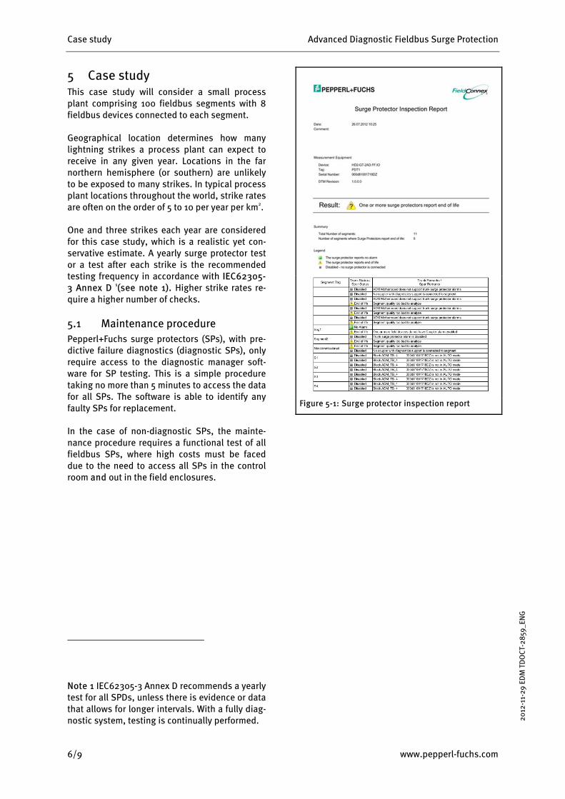
5 Case study This case study will consider a small process plant comprising 100 fieldbus segments with 8 fieldbus devices connected to each segment.
Geographical location determines how many lightning strikes a process plant can expect to receive in any given year. Locations in the far northern hemisphere (or southern) are unlikely to be exposed to many strikes. In typical process plant locations throughout the world, strike rates are often on the order of 5 to 10 per year per km2.
One and three strikes each year are considered for this case study, which is a realistic yet con-servative estimate. A yearly surge protector test or a test after each strike is the recommended testing frequency in accordance with IEC62305-3 Annex D 1(see note 1). Higher strike rates re-quire a higher number of checks.
5.1 Maintenance procedure Pepperl+Fuchs surge protectors (SPs), with pre-dictive failure diagnostics (diagnostic SPs), only require access to the diagnostic manager soft-ware for SP testing. This is a simple procedure taking no more than 5 minutes to access the data for all SPs. The software is able to identify any faulty SPs for replacement.
In the case of non-diagnostic SPs, the mainte-nance procedure requires a functional test of all fieldbus SPs, where high costs must be faced due to the need to access all SPs in the control room and out in the field enclosures.
Note 1 IEC62305-3 Annex D recommends a yearly test for all SPDs, unless there is evidence or data that allows for longer intervals. With a fully diag-nostic system, testing is continually performed.
Figure 5-1: Surge protector inspection report

Advanced Diagnostic Fieldbus Surge Protection Case study
www.pepperl-fuchs.com 7/9
2012
-11-
29 E
DM
TD
OCT
-285
9_EN
G
Figure 5-2: Strikes per year per km2
5.2 Cost Comparison Of course, diagnostic SPs with predictive failure diagnostics are more expensive when compared to non-diagnostic SPs. However, for Pepperl+ Fuchs diagnostic SPs, there are no additional wiring requirements. As a result, the costs for implementing a diagnostic communication sys-tem, apart from the additional hardware costs, are zero.
However, the additional costs for diag-nostic SPs can be recovered in a very short time period:
Table 1: System Dimension
Automation Infrastructure Count
Number of segments 100
Number of devices/segment 8
Number of devices 800
Number of SPs/segment 18
Total number of Surge Protectors 1,800
Table 2: Cost base
Case study figures Value
Average number of strikes/year 1 or 3
Added costs of diagnostic SPs $35 US
Hourly maintenance costs $70 US
With diagnostics
Operate diagnostic manager S/W 5 min
Costs for procedure at each strike event:
0.083 hrs x $70 $6 total
Without diagnostics
Test & report time per device 10 min
Costs for testing at each strike event:
1,800 x $70/hr x 10 mins $21,600

Case study Advanced Diagnostic Fieldbus Surge Protection
8/9 www.pepperl-fuchs.com
2012
-11-
29 E
DM
TD
OCT
-285
9_EN
G
Table 3: Cost calculation with ONE strike per year
Product and costs Product
cost
YEAR
TOTAL 1 2 3 4 5
Inspection/reporting costs for non-
diagnostic SPs - 21,600 21,600 21,600 21,600 21,600 $108,000
Additional costs for diagnostic monitoring hardware. 1,800 x $35
63,000 - - - - - $63,000
Inspection/reporting costs for diagnostic SPs
- 6 6 6 6 6 $30
BREAK EVEN X (4 Years)
Total cost over 5 years Non-diagnostic Surge Protectors $108,000
Diagnostic Surge Protectors $63,030
Table 4: Cost calculation with THREE strike per year
Products and Activities Product
cost
YEAR
TOTAL 1 2 3 4 5
Inspection/reporting costs for non-
diagnostic SPs - 64,800 64,800 64,800 64,800 64,800 $324,000
Additional costs for diagnostic monitoring hardware. 1,800 x $35
63,000 - - - - - $63,000
Inspection/reporting costs for diagnostic SPs
- 18 18 18 18 18 $90
BREAK EVEN X (2 Years)
Total cost over 5 years Non-diagnostic Surge Protectors $324,000
Diagnostic Surge Protectors $63,090

Advanced Diagnostic Fieldbus Surge Protection Summary
www.pepperl-fuchs.com 9/9
2012
-11-
29 E
DM
TD
OCT
-285
9_EN
G
6 Summary Utilizing qualitative and quantitative measure-ments for surge component stress monitoring and failure prediction, combined with online physical layer monitoring, significantly increases fieldbus segment availability through early warn-ing and proactive maintenance. The solution certainly takes away the need for testing every surge protector yearly and/or after each light-ning strike. This reduction in testing and unnec-essary replacement of surge protection devices is a significant savings in overall maintenance costs, particularly where work permits or gas clearance is required for each site visit.
Economically, the diagnostic system makes sense with its use of the existing diagnostic in-frastructure. Therefore, the added cost of diag-nostic integration is initially low and the hard-ware cost for surge protection diagnostics is recovered within a very short time frame.
Without doubt, this combined diagnostic ap-proach is an important step in the prevention of a fieldbus segment failure in what is essentially a product protection system.
7 References [1] Pepperl+Fuchs white paper: "Fieldbus test-
ing with online Physical Layer Diagnostics," 2007
[2] Pepperl+Fuchs white paper: “Advanced online Physical Layer Diagnostics,” 2008
[3] Pepperl+Fuchs white paper: ”Advanced di-agnostic Fieldbus Surge Protection,” 2012
[4] IEC62305-3 Annex D titled "Additional infor-mation for LPS in the case of structures with a risk of explosion."
[5] Surge Protection Anthology, April 2003. By various authors.
[6] "Effectiveness of worldwide existing ESE lightning protection systems manufactured in Europe."

S
ubject to reasonable modifications due to technical advances • Copyright PEPPERL+FUCHS • Printed in Germany • Part No: 250719 11/2012