type: xx - rheavendors.surheavendors.su/.../2014/10/man1920124-rel.-01-manuale-barista_gb.pdf ·...
TRANSCRIPT
INSTALLATION AND MAINTENANCE MANUALOriginal instructions
MAN1920124 rel. 01 dated 23.09.2011
_________________________________________www.rheavendors.com
copertina
type: XX

copertina 2
Company names; implementation of safety warnings, general information and maintenance;23.09.201101
First issue;17.11.201000
DESCRIPTIONDATEREL.
notes
by
MAN1920124 rel. 01 dated 23.09.2011 page no. 2 of 48 pages

these conditions regulate Rheavendors Industries S.p.A.’s obligations with reference to guarantee and repair; any other term or condition, either verbal or written, is not applicable, including those in the purchaser’s purchase orders, if not explicitly accepted and signed by Rheavendors Industries S.p.A.; if the guarantee terms here below should be held not to be valid and/or lawful inthe Country where the product is sold, they will not be effective whereas all the other clauses will remain valid and applicable;
the mechanical and electronic components of the machine are guaranteed for twelve months, starting from the sales date certified by the fiscal receipt;
the guarantee shall be understood as the free replacement or repair of any part of the machine that – at the manufacturer’s unquestionable discretion – should prove to be originally defective due to manufacturing defects; the cost of sending the manufacturer machines, defective pieces and spare parts will be totally charged to the user’s account; the manufacturer reserves the right to use new or reconditioned components for repair; if replaced, original components will be guaranteed for 12 months; the parts replaced under guarantee will become the property ofRheavendors Services S.p.A. (request for “Form PO 19.01/2b”Materials under guarantee – Authorisation to return);
in case of irreparable failure or if a failure of the same origin is repeated, the manufacturer may – at its unquestionable discretion – replace the machine with another one, the model of which is either the same or an equivalent one; the guarantee of the new machine will be extended up to the original term of guarantee ofthe replaced machine;
all the parts that should prove to be defective due to negligence or carelessness (non-observance of the instructions for the operation of the machine), incorrect installation or maintenance by unauthorised personnel, transport damage or any circumstance –anyway – not due to the manufacturing defects of the machine are not covered by guarantee; the installation and connection with supply plants as well as the maintenance operations mentioned bythe installation manual are also excluded from any performance under guarantee; the guarantee will not cover payment systems either; whether installed on the machine or supplied as an accessory, they are subject to their manufacturer’s guarantee whereas Rheavendors Industries S.p.A. will just act as a broker;all changes made to the machine and not agreed with the manufacturer in writing will involve the immediate termination of the guarantee period and anyway fall under the Customer’s total responsibility;
the guarantee is excluded in all cases of improper use of the machine;
Rheavendors Industries S.p.A. will disclaim all responsibility for any damage that may be directly or indirectly caused to people, animals or things as a result of: improper use of the vending machine; incorrect installation; improper energy or water supply; serious maintenance deficiency;actions or changes not explicitly authorised; use of non original spare parts;
in case of failure, Rheavendors Industries S.p.A. is obliged neither to compensate any economic damage due a forced stop of the machine nor to extend the guarantee period;
if the machine should be transferred to a centre designated by the manufacturer for overhaul or repair, the relative transportationrisks and costs will be charged to the user’s account. The freight charges of machines, defective pieces and spare parts are alwaysunderstood as charged to the user’s account;
General guarantee conditions
1st
2nd
3rd
4th
5th
6th
7th
MAN1920124 rel. 01 dated 23.09.2011 page no. 3 of 48 pages
garanziaby

Rheavendors Industries S.p.A. declares that this vending machinehas been designed and manufactured in compliance with the following directives and safety standards:
Directives:2004/108/EC; 2006/95/EC; 2006/42EC;2002/95/EC (RoHS); 2002/96/EC (RAEE); 1907/2006/EC (REACH); 1935/2004/EC;
Standards:SAFETY part. 2-75: (particular requirements for commercial dispensing appliances and vending machines) +CEI EN 60335-2-75/A12;EN 60335-1: 2002 + A1: 2004 + A2: 2006 + A11: 2004 + A12:2006 + A13: 2008 + A14: 2010 +60335-1/EC: 2010;EN 60335-2-75: 2004 + A1: 2005 + A11: 2006 + A2: 2008 + A12: 2010;
EMC:EN 55014-1: 2006 + A1: 2009;EN 55014-2: 1997 + A1: 2001 + A2: 2008;EN 61000-3-2: 2006 + A1: 2009 + A2: 2009;EN 61000-3-3: 2008;
EMF:EN 62233: 2008;
manufacturer of the machine
Rheavendors Industries S.p.A.Via Garavaglia, 5821042 Caronno PertusellaVareseItalia
The Legal Representative
(A. D. Majer )
declaration of conformity
ISO 9001 certification
dichiar. conf.by
MAN1920124 rel. 01 dated 23.09.2011 page no. 4 of 48 pages

legend
introduction
technical data
configurations
presentation
preliminary actions
connections
first power on
programming
maintenance
solution of problems
parameters
how to do to…
espresso hydraulic diagram
instant hydraulic diagram
addendum Light
in the listed chapters, the manual describes a Barista vending machine in its hardware and software components for a complete and fully-aware use of all machine functions; due to the large variety of available options and the constant technical update of our vending machines, some special device or function might be indicated and described not in the manner you expect; in this case, do not hesitate to contact us;
telephone: 0039 02 966 551fax: 0039 02 96 55 086
e mail: [email protected]
ATTENTION: this label applied next to the serial number label inside the vending machine points out that the instructions supplied by this manual must be carefully read before the installation and operation of the vending machine;
please, print this manual only if necessary; environmental protection is our common interest;
page 06
page 07
page 08
page 10
page 12
page 23
page 24
page 25
page 27
page 34
page 37
page 39
page 40
page 42
page 43
page 44
table of contents
01.
02.
03.
04.
05.
06.
07.
08.
09.
10.
11.
12.
13.
14.
15.
16.
indiceby
MAN1920124 rel. 01 dated 23.09.2011 page no. 5 of 48 pages

legendaby
MAN1920124 rel. 01 dated 23.09.2011 page no. 6 of 48 pages
01. legend
01.01. abbreviations and pictograms
I =E =
A =R =
=VSF =
=
=
=
01.02. symbols of attention
01.03. tools
some general instructions that may be of use for reference to this manual;
dispensing cycle of drinks based on instant products; dispensing cycle of drinks based on instant products and coffee beans;machines with internal water tank;machines with external water supply;
mixer for mixing the instant product with water;worm screw pitch in the product canister;product shaker for instant canisters;
espresso coffee brewer;
hot water dispenser;
if the text is highlit by this symbol, it is recommended to pay special attention to the performance of the procedures described; if not carefully performed on safe conditions, they can be source of general danger;
if not properly performed, the actions marked by this symbol mayexpose to accidental contacts with electric voltage;
if not properly performed, the actions marked by this symbol mayexpose to accidental contacts with high-temperature parts;
the same symbols can be found inside the vending machine to specify the parts on which to act with the outmost care;
the symbol recommends the utmost attention during the actions described; the use of the service key intended to activate all machine functions when the door is open is only reserved to the technical operators who know the operation of the vending machine, who are aware of potential risks and who make sure theyare operating on totally safe conditions;the use of the service key shall be strictly limited to the timenecessary to perform the actions requiring the use thereof; users shall be informed of the prohibition on using and approaching the vending machine;
the symbol means that it is forbidden to dispose of the equipment as urban waste and compulsory to provide for separate collection in order to prevent any potential effect on the environment and human health; strictly follow the provisions of the European Parliament’s 2002/96/EC Directive;
some tools commonly used and easy to find are necessary to act with this vending machine:
- a pair of scissors for electricians;- a star screwdriver 4/6 mm;- a set of fixed wrenches up to 13 mm;- a set of socket head screws from 2 to 8 mm;
it may be of use to procure some expendables, such as disposablepaper, single-use gloves, clean cloths, cups and a bucket for the collection of waste water;
§

© Rheavendors Industries S.p.A.; all rights reserved;this document contains some confidential information of Rheavendors Industries S.p.A.’s exclusive property; the content of this document can be neither disclosed in favour of third parties, nor copied or reproduced in any form whatsoever, either fully orpartially, without Rheavendors Industries S.p.A.’s prior authorisation in writing; the utilisation, reproduction or disclosure of the technical information in this document can be protected by Rheavendors Industries S.p.A. according to the Law;
this manual is intended for the owner of the vending machine; it is an integral part of the machine and it shall be kept with it;
the information supplied by this manual are intended to achieve the best performances of the vending machine within the scope ofapplication established by the Manufacturer; Rheavendors Industries S.p.A. reserves the right to improve future production without serving any prior notice and without assuming any obligation to update the products on the market; the manufacturer will disclaim all responsibility for any inaccuracy due to misprints;
safety rules for using the vending machine
** pay special attention to the chapters and notes high lit by the symbols of alert; strictly observe the rules concerning, in particular, the operators’ and users’ safety;
** under no circumstance may the vending machine be used by children or by people with poorer physical, sensorial or mental capacities or who have not been properly informed on correct use; children shall be supervised to prevent them from playing with the vending machine;
** if you should find out a water leak or the presence of smoke, immediately detach the vending machine from the electric and hydraulic network, never try to restore its operation and apply to skilled technicians;
** the machine shall be installed according to national rules; pay special attention to the rules about the machines directly connected with the hydraulic network;
** the user is not allowed to access the maintaining and servicing area that shall be properly signalled;
** never remove protections, never override safety devices and never modify the machine or its components;
Rheavendors Services S.p.A. is at disposal for any kind of support and information on this vending machine;
telephone: 0039 02 966 551fax: 0039 02 96 55 086
e mail: [email protected]
for any reference about our partners all over the world please visit site :
www.rheavendors.com
to be able to identify the vending machine rapidly and univocally as well as to get the best support, please specify the data of the serial number label;
code : D12345A67890s/n: 1234 56 7890
silvery serial number labels are applied inside and outside the case of the machine;
02. introduction
02.01. copyright information
02.02. rules
**
**
**
**
**
**
02.03. contacts
02.04. serial number labels
introduzione
(example)
by
MAN1920124 rel. 01 dated 23.09.2011 page no. 7 of 48 pages

height (including the 30 mm upper rail):width: depth: depth with open door:
instant machine:espresso machine:
- connection by means of a solenoid valve with 3/8“ gas male face:- supply by a submersible pump:- connection from internal tank;
- 230 V ac (110 V ac), 50/60 Hz; single-phase and ground;- cable of the following type: H05VV-F 3G 1 mm² 300/500 V;
anyway refer to label data
A-weighted sound pressure level;
eight selection buttons;
two sixteen-character lines;
door lighting with neon tube; light indicator blinking during the dispensing cycle;
open; folding cup support (useful height 90 mm);
drip tray beneath the cup surface;
a fixed dispensing place;
in the instant machine, overflow sensor; in the espresso machine, overflow sensor and pressure relief valve; in all machines water inlet solenoid valve with anti-flood sensor;
a main switch, a door switch;two 6.3x32 mm fuses;
manually resettable sensors;thermofuses;
time limits for water dispensing cycles;
in the espresso machine:
in the espresso machine, conical;
made of plastics; the dimension of the brewing chamber can be mechanically programmed in three volumes:
in the espresso machine, air break with overflow and level switch;
in the instant machine:in the espresso machine:
max. three , according to the machine configuration;
max. two in the instant version, max. one in the espresso version, according to the machine configuration;
max. two in the instant version, max. one in the espresso version, according to the machine configuration;
instant machine: open-top boiler;espresso machine: heat-exchanger for espresso;
open-top boiler for instant products;
600 mm300 mm455 mm700 mm
20 kg30 kg
from 0.1 MPa to 0.8 MPa24 V dc, 1.2 A max.;2,2 litre capacity
in I: 1.400 Win E: 2.100 W
less than 70 dB(A)
220 V ac; 6 W; 210 mm
maximum 150 mm
capacity 750 ml
220 V ac; 12 A delayed
88 °C121 °C
220 V ac
Ø 40 mmorange chamberØ 36 mmblack chamber
24 V dc220 V ac
95 r.p.m. 24 V dc
15.000 r.p.m. 24 V dc
3,4 litres, 1.300 W700 W1,3 litres, 1.300 W
03. technical data
03.01. dimensions
03.02. weight
03.03. supplywater
energy
03.04. sound pressure
03.05. keyboard
03.06. display
03.07. lighting
03.08. dispensing cpt.
03.09. drip tray
03.10. dispenser
03.11. safetywater
energy
heat
software
03.12. grinder motor
03.13. grinders
03.14. coffee brewer
03.15. air break
03.16. pump
03.17. product motors
03.18. mixing bowls
03.19. mixer motors
03.20. boiler
dati tecniciby
MAN1920124 rel. 01 dated 23.09.2011 page no. 8 of 48 pages

max. three, according to the machine configuration; single (55 mm) or double (110 mm) width; dispensing worm screws 9 mm or 18 mm in pitch; with mixer gear and stirrer, if arranged by the configuration and with standard or shorter product slide outlet (see 05.24.);
- coffee beans canister (or hopper) capacity: 1.0 kg
- instant canister capacity:
machine parameters programmable by means of a flash key or selection keyboard; data collection by means of a flash key (see 09.06.);
the water and energy supply tolerance limits that can ensure a good and proper operation of the Barista machine are:
water:
- total hardness:- recommended conductivity:
(*) if harder, please use anti-limestone filters;
energy:
- nominal voltage: - nominal frequency:
room (during storage and operation):
- temperature:- relative humidity:
electric consumption:
- power (vending fase):
the complete data according to the EVA-EMP Energy Measurement Protocol, are made available upon request (see 02.03.);
the power supply cable supplied with the vending machine shall not be altered under any circumstance; in case of loss or damage replace it by using an original component only;
make sure that the electric installation can deliver the power suitable for the machine (see 03.03.); a good ground connection is not only a legal obligation for the protection of users and operators, but it can also provide for correct power supply;
from 10 °F to 25 °F (*)400 μS @ 20 °C
+10 % /- 25 %+/- 5 %
5 °C ÷ 35 °Cmax. 80 %
from 34 Wh to 430 Wh
03.21. product canisters
03.22. miscellaneous
03.23. notes
dati tecniciby
MAN1920124 rel. 01 dated 23.09.2011 page no. 9 of 48 pages
width 55 mm width 110 mm capacity 1.7 litres capacity 3.5 litres
coffee 0.33 kg milk 0.38 kg milk 0.80 kg chocolate 0.94 kg chocolate 2.20 kg tea 0.98 kg

Barista configurations are numerous; they are coded by means of some categories exemplified here below in the abbreviation of the machine:
- instant products only:- instant products and coffee beans:- number of instant products and coffee beans (if E):
- - external, by means of the inlet solenoid valve:- - internal, from the internal tank to the vending machine:
product canisters, mixing bowls and mixers are numbered in progression, from the left to the right, as it is shown later on; this numbering is used in the chapter on how to programme (see 09.) drinks;
V.M. Barista I/3 A
V.M Barista E/3 R
the configurations above are just some of possible Baristaconfigurations, considering the vending machine releases and programmability; the principles of operation and information areanyway universal and applicable to all machines of the Baristarange;
to complete and supplement the vending machines of the Baristarange, Rheavendors Industries S.p.A. has got a series of accessories manufactured for these machines, such as cabinets, autonomous water supply kits, …;
Rheavendors Services S.p.A. is at disposal for any kind of support and information on special configurations (see 02.03.)
04. configurations
04.01.
a. instantb. instant and espressoc. product canisters
d. water supply
e. numbering
04.02. examples ofconfigurations
04.03. accessories
configurazioni
Barista IBarista EBarista E/4; Barista I/5Barista E/4 RBarista E/3 A
keyboard selections
1. short coffee2. long coffee3. white coffee4. cappuccino5. capp-ciocc6. latte macchiato7. chocolate8. hot water
keyboard selections
1. short coffee2. long coffee3. white coffee4. cappuccino5. capp-ciocc6. latte macchiato7. chocolate8. hot water
by
330grams
CO
FFEE
3VSF9VSF 18
380grams
MIL
K
2
940grams
CH
OC
OLA
TE
VSF18
1
§
2,2litres
WA
TER
water 1
mixer 1
water 2
mixer 2
CH
OC
OLA
TE
2200grams
VSF18§
1
380grams
MIL
K
VSF9
2
CO
FFE
E B
EA
NS
1000grams
water 1
mixer 1
MAN1920124 rel. 01 dated 23.09.2011 page no. 10 of 48 pages

Barista can produce a drink called Latte Macchiato, composed by milk and coffee and served in the cup in differently coloured bands, typically milk, coffee and milk;
to get this special drink, refer to a specific package of instructions, every step of which is called “LM dispensing cycle”; please keep in mind some general principles to achieve this special drink quality:
- the first milk dispensing cycle shall not be too much mixed;- the second milk dispensing cycle should occur after 10/15
seconds; mixing shall be extended and performed at the maximum rotation speed of the impeller;
- the espresso coffee should be dispensed at least 15/20 seconds after the second milk dispensing cycle in the cup;
the data supplied by the table provide for a “latte macchiato”dispensing cycle and they can be adapted to achieve dispensing cycles more suitable for the users’ wishes;
04.04. LM selection
LMby
MAN1920124 rel. 01 dated 23.09.2011 page no. 11 of 48 pages
parameters values
1st milkparameters
time prod n 24start delay prod n 5water time n 60
prod n start delay water n 0time mixer n 60
water n start delay mixer n 3speed mixer n low
mixer n
2nd milk
prod LM time prod LM 24start delay prod LM 200
water LM water LM time 60start delay water LM 150
mixer LM time mixer LM 80start delay mixer LM 180speed mixer LM high
coffee water2nd delay
espresso coffee start 200
sele
ctio
n
1st
m
ilk
1st
del
ay
2nd
milk
2nd
dela
y
"Latte Macchiato" selection
flow diagram
time

espresso
instant
05. presentation
E-I
05.05. orange panel in espresso machines
05.08. door lock
05.04. display
by
05.02. selection keyboard
05.09. drip tray
05.07. dispenser
MAN1920124 rel. 01 dated 23.09.2011 page no. 12 of 48 pages
05.03. selection label pocket
05.06. orange light indicator
flap support for cups
05.05. light blue panel
in instant product machines
rail stop cups
05.06. light blue light indicator
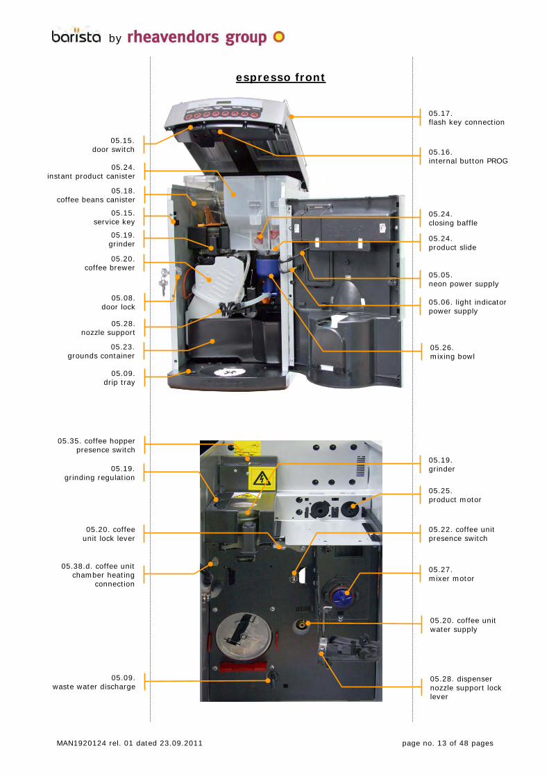
espresso front
espresso fronte
05.19. grinder
05.25. product motor
05.24. instant product canister
05.19. grinder
05.20. coffee brewer
05.23. grounds container
05.09. drip tray
05.18. coffee beans canister
05.24. product slide
05.26. mixing bowl
05.28. nozzle support
05.16. internal button PROG
by
05.15. service key
05.15. door switch
05.08. door lock
05.24. closing baffle
MAN1920124 rel. 01 dated 23.09.2011 page no. 13 of 48 pages
05.17. flash key connection
05.06. light indicator power supply
05.05. neon power supply
05.09. waste water discharge
05.38.d. coffee unit chamber heating
connection
05.35. coffee hopper presence switch
05.20. coffee unit lock lever
05.19. grinding regulation
05.27. mixer motor
05.22. coffee unit presence switch
05.28. dispenser nozzle support lock lever
05.20. coffee unit water supply

espresso rear
espresso retro
05.36. boiler
05.38.d. resistor supply
05.38.a. CPU
05.31. environment aspirator
05.32. air break
05.12. fuses
05.30. powder aspirator
05.36. heat exchanger
05.27. mixer motor
05.31. environment aspirator
05.12. fuses
05.11. power on switch
05.10. electric connection
by
05.38.c. expansion board
05.25. product motor
05.34. heat exchanger pump
boiler outlet hose
05.14. water inlet solenoid valve
05.30. powder aspirator
05.14. water inlet solenoid valve
MAN1920124 rel. 01 dated 23.09.2011 page no. 14 of 48 pages
toroidal transformer

pump motor
level probethree-way valve outlet
water outlet
boiler temperature probe
05.32. air break
clicson
heat exchanger temperature probe
05.33. volumetric counter
espresso internoby
B
A
A
A
05.27. mixer motor
05.19. grinder motor
05.21. coffee brewer motor
A
MAN1920124 rel. 01 dated 23.09.2011 page no. 15 of 48 pages
espresso
to extract the slide including the fundamental components of thevending machine, just remove the three screws A and separate thetwo electric connectors B after having removed the coffee unit (see 13.05.) and the connectors of the temperature probes (see 05.38.a. and c.); now, you can extract the slide from the machine cabinet;
after having extracted the slide of hydraulic components from the cabinet, some “internal” parts can be easily inspected and accessed; e.g. if the machine is disassembled this way, you can easily set up the right phase of the coffee unit, which shall beexactly in the position of the picture during the brewing phase;
the central articulation of the connecting rod shall be “moved backwards” by some degrees compared to the ideal line joining the axis of rotation of the unit and the upper end of the connectingrod;
to achieve this result:
- loosen the socket head screw A;- adjust the switch position by rotating the support as well as by
anticipating or postponing the cam trip on the switch lever;- screw the socket head screw again;
05.22. coffee unit presence switch
coffee unit rotation switch
coffee unit rotation switch regulation

05.24. instant product canister
05.09. drip tray
05.24. product slide
05.26. mixing bowl
05.28. nozzle support
05.29. water door
05.16. internal button PROG
05.08. door lock
05.24. closing baffle
instant front and rear
fronte e retro solubileby
05.14.water inlet solenoid valve
05.38.a. CPU
05.12. fuses
05.10. electric connection
05.11. power on switch
05.25. product motor
05.27. mixer motor
05.31. environment aspirator
05.30. powder aspirator
05.37. pump motor
05.37. boiler
05.13.water drain plug
05.29. internal water tank
MAN1920124 rel. 01 dated 23.09.2011 page no. 16 of 48 pages
05.06. light indicator power supply
05.05. neon power supply

05
02
0403
08 06
07
09
presentazioneby
11
12
1013
14
MAN1920124 rel. 01 dated 23.09.2011 page no. 17 of 48 pages
the Rhea Barista vending machine is a machine explicitly designed for being easily used by all users since no specific competence is required in preparing drinks;
the function consists in dispensing drinks by mixing food products and water at a proper temperature; the correct operation of the vending machine occurs in closed rooms in normal environmental conditions and at a room temperature between 5° and 35°C, the relative humidity below 80%;
use only specific ingredients for vending machines;
dispense by briefly pressing a key of the selection keyboard (see 05.02.); make sure that the cup has been properly positioned at the dispensing station, if necessary by using the flap support for caps (see 03.08.);
after having closed the door, press the buttons to dispense; keys will assume various functions in the programming mode (see 09.) and enable the user to modify the machine parameters; keys are numbered progressively from the left: 1, 2, …;
the front cover side just above the selection pushbutton panel accommodates the pocket where to insert the stripe specifying the names of the selections you can obtain;
the display messages inform users and operators about the operation state of the vending machine;
the front panel of the door is lighted by a neon tube arranged in a door compartment; the panel is orange in the espresso machine and light blue in the instant machine;
a light indicator is blinking (colours as above) during the dispensing cycle of drinks;
the Barista vending machine has got a fixed drink dispenser on the cup support surface;
the door is closed by means of a lock; the key is mapped and numbered for identification;
it collects all residual drops from the dispenser and, if necessary, the waste water in excess from the boiler; it is slided at the bottom of the machine case, in the front, and it is composed by a covering drawer and a grilled cover that can be washed by running water; an electric contact is intended to control the filling level (see 10.01. and 13.01.); the floater is raised if the content is in excess;
a three-terminal socket is arranged at the back of the case for the connection of the mains cable;
to power on and off the machine;
installed on the mains power supply (see 03.11.);
from where to let the silicone tube from the boiler come out foremptying, in I machines;
the water inlet solenoid valve on R machines only has got an anti-flood safety device intended to stop the water inlet in case of failures; to its electrical pins can be connected in parallel an any submersible pump (see 03.03.);
05.01. general information
05.02. selection keyboard
05.03. selection label pocket
05.04. display
05.05. door lighting
05.06. light indicator
05.07. dispenser
05.08. door lock
05.09. drip tray
05.10. electric connection
05.11. power on switch
05.12. fuses
05.13. water drain plug
05.14. water inlet solenoid valve

presentazioneby
18
19
20
23
24
26
1516
17
25
MAN1920124 rel. 01 dated 23.09.2011 page no. 18 of 48 pages
to power off the machine when the door is open;
attentionsome parts remain anyway network-connected
act extremely carefully
use the service key to supply the vending machine if it is necessary to activate the machine when the door is open; the service key is in a support on the left wall inside the vending machine;
the button giving access to the programming mode of the machine is arranged inside the door at the bottom of the cover (PROG);
the connection for insertion of the flash key is made available on the cover, on the right side;
it contains coffee beans, it is protected by a cover; an orange closing baffle enables the operator to lift it on safe conditions;
the grinder grinds the coffee beans in the hopper to pour them into the coffee unit underneath; the grinding degree can be adjusted by means of the index inside the semicircular sector;
after having received and compressed the ground dose, the coffeeunit will brew it with the water coming from the pump; the used dose is conveyed to the grounds container (see 05.23.); it is fastened by means of a lever;
the coffee brewer motor will rotate some parts of the coffee brewer to compress ground coffee for brewing; rotation is controlled by a switch driven by a cam that will inform the CPU on the position of the brewer;
a switch makes sure that the coffee unit is properly installed to prevent it from dispensing espresso in case of shortage;
it collects over sixty ground doses in E machines after having used them in the coffee brewer; a software option (see 09.01.n.) willshow a warning message as soon as the tray is full;
instant product canisters dispense their content in the underlying mixing bowls; an internal worm screw driven by the product motorwill push the instant product to the product slide; they can be equipped with a wheel and a stirrer for constant dispensing; theoutlet, the dimension of which can be either standard or smaller, has got a closing baffle;
the coffee bean canister (hopper) has a closing blade for insertion before lifting it and a metal tongue that enables the machine todispense espresso drinks after having inserted it into its seat (see 05.35);
to protect the products, canisters are closed by a cover; the versions not connected with the water mains are complete with a water tank in the place of a product canister and it can be filled through a cover hatch of the vending machine (see 05.29.);
they are intended to rotate the worm screws inside instant product canisters to pour the product quantity necessary for selection in the mixing bowls;
the mixing bowls of the mixers will accommodate the instant products you have poured to mix them with water; the fan of mixer motors will act at the bottom and the drink outflow to the dispenser occurs by means of a silicone tube; mixing bowls and outlet tubes can be washed with lukewarm running water;
05.15. door switch
05.16. internal button (PROG)
05.17. flash key connection
05.18. coffee beans canister
05.19. grinder
05.20. coffee brewer
05.21. coffee brewer motor
05.22. coffee unit presence switch
05.23. grounds container
05.24. product canisters
05.25. product motors
05.26. mixing bowls

presentazioneby
MAN1920124 rel. 01 dated 23.09.2011 page no. 19 of 48 pages
the motors of mixers help to mix instant products with water by means of the rotation of the fan mounted on their axis; the rotation speed can be adjusted (see 09.01.a.) to the features of the various products;
a support on the cup station accommodates the dispensers coming from the mixer bowls; it can be locked in its open position for a better access to the machine;
only in A machines, on the cover of the vending machine, a door enables the operator to access the water tank inside for fillingpurposes; the tank is complete with a floater signalling by means of a red stripe that it has been filled in excess;
an aspirator will eject suspended product residuals from the vending machine; the aspirator is connected with a drawer to intercept the residual impalpable powder coming from selections;the action time of the aspirator is programmable by means of a software parameter (see 13.18. and 09.01.f.); aspirated air is ejected through the slots of the rear panel;
to aspirate the air from the internal environment of the machine to avoid any condensate;
in E machines, it accumulates water for conveyance to the heat exchanger; the level is controlled by a switch operated by a floater and, if higher than established, it will flow back to the safety device of the inlet solenoid valve, thus preventing further water from flowing in;
for the espresso version only, it supplies the CPU with the water quantity flowing through the coffee unit to determine its volumeand dispense the espresso you wish;the water quantity of instant selections is established by the time set in the “water N” parameter only (see 09.01.a.);
in E machines, a vibration pump with by pass conveys water to the heat exchanger supplying the espresso hydraulic circuit;
this switch is pressed when the coffee hopper is installed in the right position; otherwise, no drink including espresso coffee will be dispensed;
05.27. mixer motor
05.28. nozzle support
05.29. water door
05.30. powder aspirator
05.31. environment aspirator
05.32. air break
05.33. volumetric counter
05.34. exchanger pump
05.35. coffee hopper switch
28
27
3433

attentionthese components may be very hot even if the machine is off;
it produces hot water for the espresso circuit; complete with temperature probe and overtemperature protection (see 09.01.e.);
it heats and accumulates water for the circuit of instant drinks; active elements (heating element, heat protections, temperature sensor, pumps) are all secured to the cover;
pumps with turbines immersed in the boiler water; water is conveyed in tubes feeding mixing bowls; (attention to the polarisation of motors; see 03.16.); the water quantity of instant selections is established by the time set in the “water N” parameter (see 09.01.a.);
05.36. espresso machine
heat exchanger
boiler
boiler pumps
05.37. instant machine
presentazione
pump name sw outlet
P1 water 1 hot water P2 water 2 mixing bowl
P2 P1
thermofuseclicson
level probe
clicsonwater inlet
water outlets
temperature probe
level probe
by
pump name sw outlet
P1 water 1 mixing bowl 1 P2 water 2 mixing bowl 2 P3 water 3 hot water
temperature probe
three-way valve
soluble pumps
P2
P3
P1
temperature probe
level probe
level probeclicsons
water outletswater outlet
soluble pumps
X2
1
1 23
MAN1920124 rel. 01 dated 23.09.2011 page no. 20 of 48 pages
heat safety

presentazione05.38. electronics
05.38.a. CPU
05.38.b. display p.c.b.
05.38.c. expansion board
05.38.d. heating element power supply
by
led 5 V d.c.
led resistenza bollitore
IN 230V a.c.
OUT bollitore
fusibile 6,15 A (12 V d.c.)
ingresso sonda temperatura bollitore
IN 24 V a.c., 5 V a.c.
alla scheda display
fusibile 2 A (5 V d.c.)
alla scheda espansione led 12 V d.c.
MAN1920124 rel. 01 dated 23.09.2011 page no. 21 of 48 pages
the CPU board controls the machine operation. It is the core of machine programmes and it is secured to the frame by means of four supports; the display cable transmits the exchange of signals with the keyboard and the display arranged in the door (see 05.02. and 05.04.); the temperature probe cable is separated from the machine wiring so as not to hamper any removal of the probe;the boiler heating element led turns on whenever the boiler heating element is activated; the two fuses protect the + 5 V and + 24 Vboard power supply;
the display board secured inside the door will accommodate the signals of the selection keyboard and display the messages; a flat cable will connect it with the CPU (see 05.04.);
the expansion board, in E machines only, is necessary to controlthe coffee brewer motor and the grinder;
some versions can heat the brewing chamber of the coffee unit; this board, which is protected by a fuse, controls the operation of the heating element;
flash key connection
programming button (PROG)
to the keyboard CPU board
connection
to the display
IN 220 V a.c. and grinder
grinder relay
exchanger pump relay
exchanger temperature probe inlet
to the CPU board
exchanger heating element led
OUT heating element exchanger and pump
to the coffee unit heating element
2A fuse
IN 24 V a.c.

presentazione05.39. software
05.40. rheAction
by
MAN1920124 rel. 01 dated 23.09.2011 page no. 22 of 48 pages
the software installed in Barista can be subdivided into two different chapters called:
- master: it is the software determining the machine cycles, the links between the functions, the order of execution of operations; this software can not be modified by the operator, but it can bereplaced in the CPU by means of a flash key written at works or by means of rheAction (see 09.06. and 05.40.);
- configuration: it is the software determining the times and the succession of dispensing drinks, the payment system protocol, the display modes, …; variables may be modified by the operator either manually aboard the machine or by means of rheAction (see 09.06. and 05.40.) to adapt the machine behaviour to the final users’ needs (product quantities and mixtures, warning messages …) (see 09.);
if it is necessary to update one of the software programmes above on the machine, the flash key may be of great use; the key can contain either software or both of them and provide for a rapid and safe transfer;
please note that the flash key used for these software handlingsmust have been previously initialised (with RheAction for example);
in general, the transfer procedure is:
- power off the machine;- insert the flash key into the corresponding connector (see
05.17.);- power on the machine by means of the service key (see 05.15.);- wait for the message on the machine display;- answer the messages on the display;- power off the machine and remove the flash key;
please note: if the flash key should contain a master software, the transfer will certainly occur from the key to the machine, whereas it will be necessary to follow the steps described by 09.06 in case of a configuration software;
a system called rheAction is intended to complete and supplement the programming executable in the machine. It is composed by a software and hardware, installable in a pc, capable of storing, modifying and writing the configuration data of Rhea machines;Rheavendors Services S.p.A. is at disposal for any kind of support and information on the RheAction system (see 02.03.);

06. preliminary actions
06.01. handling
06.02. unpacking
06.03. positioning
06.04. preparation
preliminariby
MAN1920124 rel. 01 dated 23.09.2011 page no. 23 of 48 pages
the vending machine may be transported, handled and positioned by skilled and trained personnel only; while handling, never overturn the machine; observe the orientation arrows on the package;
attention
handle the machine carefully to prevent the authorised personnelfrom being injured; considering the weight and overall dimensions of the vending machine, it is recommended to use a truck at low speed;
- approach the packed vending machine to its work position;
- cut the two plastic belts;
- lift the external package;
- remove the drip tray;
- extract the protection bag up;
- lift the vending machine and arrange it on the work surface;
attention
the materials composing the package shall never be left within the reach of people from outside, in particular of children, because they represent a potential source of danger; only specialised companies may be charged to provide for the disposal of package components;
the vending machine shall be arranged for work in a sheltered room by using a support suitable for the weight of the machine (see 03.02.); its distance from the walls shall provide for good air circulation and easy access;
any inclination of the surface shall not exceed 2°;
it is recommended to arrange an easily cleanable impermeable protection beneath the vending machine to collect any accidentalproduct fall;
when the machine is in its final working position:
- cut the clamp intended to secure the door key to the drip tray grilled cover;
- insert it into the lock (see 05.08.), rotate it and open the door;
- remove the envelope of documents;
- take the box of accessories;
- take the power supply cable and the water union; the water union can be used for water connection with the network;
- screw the four feet to the lower case corners by adjusting them for proper inclination (see 06.03.);

connessioniby
MAN1920124 rel. 01 dated 23.09.2011 page no. 24 of 48 pages
07. connections
07.01. water
07.02. energy
make sure that the water used to supply the vending machine has all proper features for human consumption;
make sure that there is no sign of impurity and check the degree of hardness; if necessary, contact an analysis lab;
if necessary, use a softening filter and replace the cartridge at regular intervals to preserve the machine components;
make sure that the network pressure is the one preset for the machine (see 03.03.); use a pump or a reducer in case of non-compliance; it is recommended to install a tap to detach the machine from the network; connection shall occur by means of a tube type-approved for food use and capable of supporting the operating pressure; if the machine is supplied by an internal water tank, make sure that the tank is properly positioned in its seat and fill it;
for the drinkability features of “waters intended for human consumption” refer to the following Internet address:
http://eur-lex.europa.eu/directive 98/83/EC of 03/11/1998
observe the rules on connections with the electric network, in particular on grounding; connect the machine permanently withoutusing any reduction, adaptor, multiple socket or extension; use the network connection cable supplied with the vending machine only;it is recommended to install a switch detaching the machine fromthe network;
it is recommended to install a differential current device operating below 30 mA, detaching the machine from the mains and promptly tripping in case of improper electric input in order to considerably reduce the risks arising out of any short-circuit;
attention
check the power plant capacity to supply the power required by the machine (see 03.03) and the observance of the rules in force; strictly refer to the data of the serial number label (see 02.04.)
insert the cable into the connection socket (see 05.07.); then, connect the plug with the socket and supply the vending machine;
for a correct and safe configuration of the electric power supply installation refer to the following Internet address, if necessary:
http://eur-lex.europa.eu/directive 2006/95/EC of 12/12/2006

08.first power on
08.01. introduction
08.02. activity
08.03. washing
after having unpacked the vending machine, arranged it firmly inthe work place and connected or supplied it (machine A) hydraulically and electrically, carry out some actions to operate it;
wash hands thoroughly with water and soap before handling the machine and the products; only use potable
water to clean the components;
open the door, lift the cover, power on the main switch of the machine (see 05.11.);
for E versions pour a small quantity of coffee beans into the coffee hopper to avoid displaying the no coffee message; never forget to pull the coffee hopper blade;
attentionarrange a cup beneath the nozzles;
insert and rotate the service key into the door switch (see 05.15.);
attention
the vending machine is supplied and running to all effects; the mobile parts of the coffee brewer will be handled; act extremelycarefully;
at the end of the assembly and final inspection, discharge the water used for tests from the machine; at the time of the first power on, fill in the whole water circuit; the machine will constantly load water and display:
wait for the water to come out of the dispensing nozzles for some seconds; the water flow will automatically stop and the display show:
water will start heating in the boiler to reach the temperature value you have set up (see 09.01.e.); at the end of this phase, the display will show the message:
transportation, storage and installation conditions can not provide for immediate utilisation of the vending machine and it is recommended to perform a complete wash cycle before using the vending machine; press the programming button (see 05.16.); the display shows alternatively the messages:
attention
the vending machine is supplied and running to all effects; the mobile parts of the coffee brewer will be handled; act extremelycarefully;arrange a cup beneath the nozzles; the machine will dispense a pre-fixed water quantity for each wash cycle;
press “4” to enable the wash cycle of the water circuit (boiler, tubes, mixing bowls, ….);the display shows:
- in the E version, key “1” will dispense water through the coffee unit; selection “2” will do it in the mixing bowl for instant products; selection “3” in the hot water outlet hole to the cup;
- for the I version, keys “1”, and “2” will dispense water into the two mixing bowls for instant products; selection “3” in the hot water outlet hole to the cup;
prima accensione
EspressoBarista
by
MAN1920124 rel. 01 dated 23.09.2011 page no. 25 of 48 pages
OFF 09 no coffee beans
3= FREE VEND1= PROGRAMMING
5= MAINTENANCE2= DATA 4= CLEAN
waitrefilling water
sel. 1-2-3cleaning
please waitswitching on…
INSTALLATION
installation end
temperature wait

repeat the operation for some times to rinse the whole water circuit of the machine; during the wash cycles, the display shows:
power off the vending machine by means of the service key; arrange it in its support; power off the main switch at the back of the machine (see 05.11.);
prepare a chlorine-based anti-bacterial sanitising solution by observing the instructions supplied with the product; remove andimmerse the following into the solution: the product canisters you have disassembled, the trays of mixers, their fans and the silicone tubes intended to dispense products; the time necessary to sanitise is specified by the anti-bacterial product package; at the end, remove all the parts you have sanitised from the solution, dry them carefully by using clean cloths and reassemble them into the machine; rotate the baffles of the product slides of instant canisters to close them and load the canisters with reference to the machine configuration (see 04.) and to the canister labels; fill in the coffee hopper (in E machines) with coffee beans; close the canisters and the coffee hopper with their upper covers;rotate the baffles of the product slides (see 05.24.) to open them and pull the orange blade intended to close the coffee hopper (in the E machine); (see also 10.);
to clean and treat food products properly, refer to the content of the following Internet address:
http://eur-lex.europa.eu//regulation 2004/852/EC of 29/04/2004
lower down the cover and close the door by means of the lock key(see 05.08.) and place it in a safe place;
power on the machine by means of the main switch; the display will show in sequence following messages:
till the water temperature of the boiler or pressure boiler is suitable for the value set in the memory (by default);
at the end of this phase intended to heat water in the boiler, the vending machine is ready to dispense on a free basis and the display will alternatively show some stand-by messages:
08.04.
08.05.
prima accensione
place cup
EspressoBarista
EspressoBarista
by
MAN1920124 rel. 01 dated 23.09.2011 page no. 26 of 48 pages
please waitswitching on…
temperature wait
cleaning N

the vending machine is programmed by means of parameters considered standard for the specific configuration required; values forming the composition of recipes – written in the board memories – enable the user to dispense drinks without requiring the installer to set up special programmes; to modify these parameters to adapt the drinks you have produced, refer to the following; at the end of the chapter (see 09.07.), a summary table may help the user trace back all the programming items;to access the programming mode, open the front door of the machine and use the service key in the safety switch;
attention
the vending machine is supplied and running to all effects in this mode of operation; act extremely carefully;
press the “PROG” key (see 05.16.); the display shows alternatively the messages:
- “1” to access the programming mode of machine variables;- “2” to display the drink quantities you have dispensed;- “3” option not to be considered;- “4” to dispense water to wash the water circuits;- “5” to schedule maintenance operations;
after having programmed, press “1” and then the key “PROG” to go back to the usual operation of the vending machine and to store all changes you have made; the display will show:
press the key “PROG”, press “1”; the buttons of the selection keyboard will assume the following functions:
the items are (scroll by means of key “1”):
contains the variable composing selection 1;
contains the variables composing selection 8;
option not to be considered;
option not to be considered;
option not to be considered;
to set up the boiler water temperatures;
to programme different options;
to display some machine parameters;
09.programming
access
quit
09.01. “prog”
09.01.a. key 1…
key 8
09.01.b. prices
09.01.c. happy price
09.01.d. coins
09.01.e. temperatures
09.01.f. miscellaneous
09.01.g. diagnostics
programmazioneby
MAN1920124 rel. 01 dated 23.09.2011 page no. 27 of 48 pages
Key 1 to scroll the items forward Key 6 to scroll the items backward Key 2 to scroll the variables of items forward Key 3 to scroll the variables of items backward Key 4 to increase the value of the variable on the screen Key 5 to decrease the value of the variable on the screen
BUTTON NPROGRAMMING
PRICESPROGRAMMING
HAPPY PRICEPROGRAMMING
COINSPROGRAMMING
TEMPERATUREPROGRAMMING
MISCELLANEOUSPROGRAMMING
DIAGOSTICS
wait ………END PROGRAMMING
3= FREE VEND1= PROGRAMMING
5= MAINTENANCE2= DATA 4= CLEAN

to display the quantity of dispensing cycles you have performed;
to set up the machine clock;
to record any failure that may have occurred;
to check and enable product dispensing cycles;
it contains the maintenance control parameters of the machine;
to determine the RFID card parameters;
press key “2” when the display shows “key n” to scroll the variables composing the function of that key;
- if you press “2” when “FUNCTIONING”, the key will perform the function you have programmed (dispensing cycle of a drink); see paragraph “functioning”;
- if you press “2” when “INHIBITED”, the key will be inhibited and it will perform no function;
use key “2” to scroll the following items:
in E machines, espresso coffee is the first product you can programme for each selection key; there are two variables:
- the water quantity in the cup; change it by means of “4” and “5”; if the variable is zero, no espresso will be dispensed (drink composed by instant products only);
- coffee will be dispensed before (value 1) or after (value 0) instant products;
press “2” to display:
parameter used in machines complete with a time doser;
press keys “4” and “5” to change the rotation time of the N product motor, thus changing the product quantity you have dispensed; iftime is zero, no product N will be dispensed; you can carry out a “time test” on the set-point; (see 13.19.);
if the time you have programmed is other than zero, the N product motor will be activated at the expiry of the delay time you haveprogrammed; the delay time is increased or decreased by pressingkeys “4” and “5”;
the rotation time of the product motor can be briefly interrupted one or two times during the dispensing cycle (0 = no break);
in the “Latte macchiato” selection,
to establish the milk quantity of the second dispensing cycle;
to determine the delay of the second milk dispensing cycle;
to determine the breaks of the second milk dispensing cycle;
to establish the time interval between the first milk dispensingcycle and the second one;
09.01.h. sales audit
09.01.i. clock
09.01.l. out of service
09.01.m. product qty
09.01.n. maintenance
09.01.o. RFID CARD
09.01.a. button from 1 to 8
“functioning”
LM dispensing
LM dispensing
LM dispensing
LM dispensing
programmazioneby
0-25 sec. 0.0Pause A/B Latte M
MAN1920124 rel. 01 dated 23.09.2011 page no. 28 of 48 pages
SALES AUDIT
PRODUCT QTYPROGRAMMING
CLOCKPROGRAMMING
OUT OF SERVICEREGISTRATION
MAINTENANCEPROGRAMMING
RFID CARDPROGRAMMING
FUNCTIONING
INHIBITED
0= inhib. 0.0COFFEE WATER
1=coffee before 0.0coffee sequence
grinder time
0= inhib. 0.0PRODUCT N
PRODUCT N 0.0start delay
0-1-2 00 breaks number
0= inhib. 0.0PRODUCT LM Xn
PRODUCT LM 0.0start delay
0-1-2 00 breaks number

to determine the pump power on time and the water quantity it will deliver; you can carry out a “time test” on the set-point; (see 13.19.);
water will be dispensed in the mixing bowls at the expiry of thedelay time you have programmed;
only for instant selections, the water flow in mixing bowls can be regulated between low, medium, high by pressing keys “4” and “5”(see 13.16.);
the rotation time of the mixer fan can be changed by pressing keys “4” and “5”; if time is equal to zero, the mixer will not rotate; you can carry out a “time test” on the set-point; (see 13.19.);
if the rotation time is other than zero, the mixer fan will be rotated at the expiry of this delay time;
the mixer rotation speed can be regulated between “0” maximum and “5” minimum by pressing keys “4” and “5” (see 13.17.);
to establish the water quantity of the second milk dispensing cycle;
to determine the water quantity delay of the second milk dispensing cycle;
to establish the mixer rotation time of the second milk dispensing cycle;
if other than zero, the mixer power on will be delayed by the time you have set up;
to determine mixer rotation speed of the second milk dispensing cycle;
to repeat the selection by N times automatically and produce drinks of remarkable volume (jug);
press “4” and “5” to choose the drink name to display during the dispensing cycle; options are listed here below:- “standard”, the display will show “drink N under preparation”;- “list of names” of drinks made available in the machine memory;
the display will show “drink name under preparation”; - “custom”: the display will show the user’s customised names; it
is necessary to create a configuration file with RheAction (see 05.40.) and load it on the machine by means of a flash key see 09.06.);
press key “2” to display:
use keys “4” and “5” to increase or decrease the boiler water temperature;
use keys “4” and “5” to change the heat exchanger temperature;
LM dispensing
LM dispensing
LM dispensing
LM dispensing
LM dispensing
09.01.e. temperature
for the I versions
for the E versions
programmazioneby
heat exchanger NN TEMPERATURE
MAN1920124 rel. 01 dated 23.09.2011 page no. 29 of 48 pages
0= inhib. 0.0WATER N time
WATER N 0.0start delay
medium water flow : N
0= inhib. 0.0MIXER N
MIXER N 0.0start delay
00 MIXER speed N
0= inhib. 0.0WATER LM time
0= inhib. 0.0delay water LM
0= inhib. 0.0MIXER LM
MIXER LM 0.0start delay
00MIXER LM speed
0=no n:00JUG
------- n:00 selection name N
boiler NN TEMPERATURE

the “miscellaneous” item includes some options (press keys “4” and “5” to modify the values of these options):
- machine code A and B: you can number the machine to distinguish it from others similar (data collection);
- message number: press keys “4” and “5” to choose the messages to display on the screen when the machine is in standby mode;
- option not to be considered;
- access code: to access the programming mode only after having typed a password you can choose by pressing keys “4” and “5”; carefully note down the combination you have chosen;
- fan delay: to determine for how many minutes after the latest dispensing cycle the powder suction fan will remain active;
- beep time: beep time active at the end of each machine function;
- option not to be considered;
- first installation: used to make sure that the water circuit will be filled in at the next power on; if the value is zero, the machine will perform the cycle just as for 08.02 at the next power on;
- the rotation time of the boiler pumps can be changed (keys “4”and “5”) by +/- 30 %; the change concerns all the activations of the pumps for all selections;
- the time required to start the grinder motor can be tuned by +/- 30%, with respect to the setup of every single selection; once established, this increase or decrease is active for each activation;
press key “2” to access diagnostics and program the machine (keys “4” and “5”) to display the water temperature value of the heat exchanger and the wait message alternatively;
this menu is intended to gather the quantities of the selectionsmade by the machine: names are assigned according to the EVA-DTS standard:
- VA 102 quantity of total vends (parameter not resettable);
- VA 104quantity of the vends made after the reset;
- VA 101total amount of receipts (parameter not resettable);
09.01.f. miscellaneous
09.01.g. diagnostics
09.01.h. sales audit
programmazioneby
MAN1920124 rel. 01 dated 23.09.2011 page no. 30 of 48 pages
A NNmachine code
B NNmachine code
Nmessage number
coin-mech type
NNaccess code
min. NNfan time
0.0Beep time
Ndecimal number
0=first Nfirst installat.
NNTOTAL SELECTIONS
0.00 TOTAL MONEY
NNPART. SELECTIONS
TEMPERA. 1=YES NHABIL. DISPLAY
percent +00 %tuning pump N
percent +00 %tuning grinder N

09.01.i. clock
09.01.l. out of service
09.01.m. product qty
programmazioneby
- VA 103total amount of receipts after the reset;
- VA 202quantity of total tests (parameter not resettable);
- VA 204quantity of tests after the reset;
- DA 401total amount loaded on RFID cards;
- DA 402total amount loaded on RFID cards after the reset;
- DA 201total amount sold by means of a RFID card;
- DA 203total amount sold by means of a RFID card after the reset;
- option not to be considered;
- option not to be considered;
- option not to be considered;
this chapter is intended to determine:
- current time;
- current day;
- day of the week;
- current month;
- current year;
option not to be considered;
option not to be considered;
for each day of the week you can establish a time band during which the machine will accept no selection and reduce the water heating of the heat exchanger;
to count the energy consumption of the machine;
to display the recording of the twenty errors last occurred in the machine; press key “2” to scroll the records and key “4” to reset the recording (see 11.);
each product motor can be assigned a time credit in seconds thatwill be decreased at each dispensing cycle of that product; after having used up the credit, the machine will answer “selection not available” whenever a request is made for that product; this control is disabled at the beginning and the machine has got no constraint; to programme the credit time of a product motor, set the variable by pressing key “4” and “5”; programmable products from 1 to 6;quit the programming mode as usual;
[ 0.0] 0.0coffee beans
MAN1920124 rel. 01 dated 23.09.2011 page no. 31 of 48 pages
00 TOTAL TESTS
00 PARTIAL TESTS
0.00 PARTIAL MONEY
card 0.00 total loaded on
card 0.00 part loaded on
card 0.00 total unloaded
card 0.00 part unloaded
00 TOTAL. SEL. N
HAPPY 00 TOTAL SEL. N
FREE 00 TOTAL SEL. N
00:00 HOUR:
00 DAY:
00 MONTH:
00 YEAR:
(ex.) Tuesday day of week
00:00 START FN:
00:00 END FN:
xxxxx 00:00 SWITCHING ON:
xxxxx 00:00 SWITCHING OFF:
0.0 Kilowatt hours:
hh:mm dd-mm-yyyy n. N off NN
[ 0.0] 0.0product qty N

in this ensemble of parameters, key “2”, you can set up some counters to trigger an alarm after a programmable number of events (press “4” and “5” to set up and PROG to store):
- dispensing cycles before having to replace the cartridge of the external filter, if any; as soon as 500 dispensing cycles are left, the display will show “change water filter” and as soon as the decounter has reached 0, it will display “out of service water filter”, thus inhibiting the operation of the machine;
- espresso dispensing cycles before having to service the coffee unit (see 12.02.); as soon as 5 dispensing cycles are left, the display will show “make brewer cleaning” and as soon as the decounter has reached 0, it will display “out of service cleaning brewer”, thus inhibiting the operation of the machine;
- espresso dispensing cycles before having to empty the grounds container (see 13.02.); as soon as the decounter has reached 5, it will display the message “remove coffee grounds” until the decounter has reached 0, thus inhibiting the operation of the machine and the display will show “out of service coffee grounds”;
- the maximum credit you can load from the RFID card;
- 0 for each coin (from A to J) that can be accepted when the RFIDcard is available;
- 0 for each coin (from A to J) that can be accepted when the RFIDcard is not available;
choose the option “data” to enable the display to show the data of the dispensing cycles you have performed in succession, just as in 09.01.h.;
option not to be considered;
choose this option and press “1”, “2”, or “3” to enable the vending machine to dispense a pre-fixed water quantity to wash the corresponding circuit (see 08.03.);the display shows:
to carry out the same functions as those described by point 09.01.n.;
the values of the variables composing the machine programming (configuration) can be transferred to an external support, i.e. the flash key; to transfer the machine parameters to the key:
- power off the machine;- open the door;- insert the flash key into the cover slot of the machine (see
05.17.);- power on the machine;- the display shows:
- press “2”- and wait for the display to show:
- power off the machine and remove the flash key;
now, the flash key contains all the parameters typical of the machine from which they have been fetched. If you wish to programme another vending machine with these data, the previous procedure can be repeated by pressing key “1” instead of “2”: the information will be transferred from the flash key to the vending machine; both procedures will not alter the data contained in the supports from which they have been fetched;
09.01.n. maintenance
09.01.o. rfid card
09.02. “data”
09.03. “test”
09.04. “clean”
09.05. “maintenance”
09.06. data support
programmazioneby
MAN1920124 rel. 01 dated 23.09.2011 page no. 32 of 48 pages
[ 00] 00 water filter cnt
0.00 max credit card
card 0=acc. coin A N
[ 00] 00 dec. cof. brewer
[ 00] 00 dec. cof. grounds
no card 0=acc. coin A N
cleaning N
sel. 1-2-3 cleaning
2 from VMC to key1 from key to VMC
wait ………END PROGRAMMING

programmazione schema
09.07. programming diagram
by
dec coffee brewer dec coffee grounds
dec coffee grounds
coin n no card
cleaning n
5. MAINT. 5 water filter cnt
4. CLEAN 4 cleaning
3. TEST
2. DATA 2 sales audit
product qty coffee beans product qty n
rfid card max credit card coin n card
maintenance water filter cnt dec coffee brewer
switching on
switching off
kilowatt hours
out of service n. NN off NN dd mm yy
month
year
day of week
start/end fn
clock hour
day
total loaded on card
part. loaded on card
total unloaded card
partial unloaded card
totale sel
total sel happy
total sel free
partial selections
total selections
beep time
decimal number
first installation
tuning pump
tuning grinder
partial test
message number
coin mech
pr.LM see details 04.04
water time n
inhibited
machine code a
machine code b
sales audit
coffe water exp1. PROG 1 button n functioning
diagnostics enable disply temp.
access code
total money
partial money
total test
fan time
miscellaneous
temperature boiler temperature
coins
heat exchanger temper.
prices
happy price
coffee sequence
grinder time
product n
start delay product n
breaks number
water flow
start delay water n
selection name
start delay mixer n
mixer speed n
numero jug
mixer n
MAN1920124 rel. 01 dated 23.09.2011 page no. 33 of 48 pages

manutenzione
the Barista vending machine requires no special maintenance procedure to do its job; however, if you provide for careful andfrequent cleaning, this may help the machine keep its performance constant, prevent failures and ensure the high quality of dispensed drinks; the frequency of cleaning operations largely depends upon the number of dispensing cycles and the hardness of water in use(use a softener system) and it shall be adjusted to the working conditions of the vending machine;
the actions described are intended to prevent the bacterial growth in the machine areas directly in contact with foodstuffs and to keep the parts conveying drink-composing products clean; after having disassembled the parts of the machine listed here below, use plenty of lukewarm water to remove any residue that might build up;
the support of a bacterialstatic or bactericidal solution may strengthen a deep cleaning action, provided it is compatible with human health and the supply of foodstuffs; reassemble all the parts you have cleaned after having dried them by means of a clean piece of cloth;
refer to the content of the Internet address:
http://ec.europa.eu/food/food/biosafety/hygienelegislation/index_en.htm
this site is intended to supply the European Parliament recommendations for properly and safely processing foodstuffs;consult also:
http://eur-lex.europa.eu//regulation 2004/852/EC of 29/04/2004
before accessing the machine for each maintenance operation, it is recommended to warn the users by means of boards properly positioned that it is forbidden to approach the vending machine and to use it;
attention
never wash the machine by using water jets;
wash hands thoroughly with water and soap before handling the machine and the products;
only use potable water;
all components must only be cleaned with warm running water;
the drip tray, the mixers and the soluble canisters can be cleaned in a dish washer using a short washer cycle with a
temperature not exceeding the 50° C;
10. maintenance
MAN1920124 rel. 01 dated 23.09.2011 page no. 34 of 48 pages
by

power off the machine; detach the power supply cable and carefully make sure that there is no sign of wear; carefully check the stability and efficiency of the internal connections of the mains supply;
use a non-abrasive piece of cloth after having dampened it with lukewarm water; only if necessary, use a neutral, non-foamy, detergent;
attention
use neutral detergent products only; never use abrasive cloths, steel sponges, aggressive or foamy detergents and other solvents, hot water and acids;
extract the drip tray, remove the upper grilled cover and wash them abundantly with water “A”; clean the seat of the drip tray and the nozzles holder spout “B”;
remove them from the product containers, wash them abundantly with lukewarm water (product slides are bayonet-fastened) “C”;
turn the fastening small levers of the mixing bowls “D”counterclockwise, remove the dispensing nozzles “B”, pull the mixing bowl and the powder suction ring; wash the assembly of disassembled parts abundantly with lukewarm water;
remove any trace of residue from the internal surfaces of the machine and clean by using a damp piece of cloth;
remove any trace of residue from the surfaces inside the door, above all in the proximity of the cup station;
carefully make sure that the motors of the two aspirators can freely rotate and have no obstacles or obstructions;make sure that the corrugated tube connecting the powder aspirator and the aspiration drawer is clean and free of any product deposit “E”;
close the slides, remove the canisters from the machine, clean them externally; clean the support surface carefully to remove any trace of product;
clean and wash the whole coffee brewer by using running water; to check, clean or replace filters and gaskets after having disassembled the unit from the machine (see 13.05.):
- unscrew the two lock screws from the setting plates “F”;
- rotate the upper piston to access the gasket as well as the upperand lower filters “G”;
- check the upper and lower piston gaskets;
- clean the upper and lower filters;
- grease the lower filter stem by using silicone-based grease for foodstuffs “H”;
10.01. weekly
external body
cups station
product slides
dispensing system
walls and bottom of the machine
internal wall of the door
10.02. monthly
environmental and powder aspirators
products canister
in E machinescoffee brewer
manutenzione
MAN1920124 rel. 01 dated 23.09.2011 page no. 35 of 48 pages
C
E
H
F
G
D
B
A
by

replace the gasket at the base of the mixing bowl of the mixer; remove the mixer motor fan by pulling it; replace the gasket of the mixer motor shaft “I”;
disassemble the products canister from the machine; empty them, disassemble them in their basic components and wash them carefully “L”;
remove the water transport tubes from the boiler at the back of the mixer surface, disassemble the mixing bowls, unscrew the two side screws intended to fasten the surface, tilt and pull it, remove the aspiration drawer; wash it abundantly with lukewarm water;
empty the boiler by means of a drain pipe; extract it from the machine, remove the cover and wash the tank by removing any solid residue that may have built up at the bottom;remove any calcareous deposit from active elements: temperature probe, heating element, level probes, the shafts of rotary pumps, …;
make sure that the water transport tubes are intact and that they have kept their transparency, replace them, if necessary;
- replace the upper and lower pistons gasket; - replace upper and lower filters; - check the status of the brewing chamber;
disassemble the heat exchanger (see 05.36.) and separate it fromthe three-way solenoid valve block; clean the espresso outlet water circuits; check the drain of the solenoid valve third way by removing any trace of residue; empty and clean the air-break tank;
if the vending machine should be inactive for a long period, please act as follows:
- in E machines, perform the uninstall cycle (see 09.01.e.);- in I machines, set the boiler water temperature to zero;- detach the water and energy supply;- in I machines, empty the boiler;- empty the liquid waste tray and the internal water tank; - empty and clean the product canisters;- clean the internal and external surfaces by using a wet piece of
cloth; - cover the machine by means of a cloth;- store it in a sheltered place, at a temperature not below 5 °C, at
a relative humidity not above 80%;
if you should definitively set the vending machine out of commission and provide for the disposal of some parts thereof, after having carried out the operations above, disassemble the vending machine by separating every single component and subdividing the parts according to the nature of materials; the applied symbol means that the components of the vending machine shall be not processed as home rubbish, but delivered to the collection points capable of recycling electric and electronic equipment; refer to the 2002/96/EC Directive and to the relativerules;
the complete text of the European directive about this specific subject-matter is made available on the Internet site:
http://eur-lex.europa.eu/directive 2002/96/EC of 27/01/2003
10.03. yearly
dispensing system
products canister
powder aspirator drawer
boiler
silicone tubes
in E machines
coffee brewer
heat exchanger
10.04. out of order
temporary
definitive
manutenzione
MAN1920124 rel. 01 dated 23.09.2011 page no. 36 of 48 pages
by
L
M
I

some malfunctions produce an error message on the display; some general information is supplied here below for these messages;
actions/comments
empty the drip tray (see 13.01.);
EAROM of the CPU board failed; replace the CPU board (see 05.38.a.);
water not supplied by the network, water supply flow rate not adequate; supply water circuit throttled or clogged; it may physiologically occur at the first power on when the boiler that is completely empty will require more time than usual to fill;
there is a control connecting water reloads with the drinks you have dispensed; if some water reloads occur without dispensing any drink, this will produce the 6B error; make sure there is noleakage in the water circuit;
there is a maximum operation time of the brewing pump, at the expiry of which error 7 is produced; check the efficiency of thewater circuit: volumetric counter, pump, three-way solenoid valve, …; brewing chamber as well as upper and lower filter of the coffee brewer; the quantity and grinding degree of coffee shall cause the machine to brew for about 10/15 seconds;
electrically and mechanically check the switch controlling the coffee brewer rotation, the control cam, the brewer rotation motor and its crank;
make sure that the brewer has properly positioned (against the support wall); check the operation of the micro switch operated by the presence of the brewer;
there is a control for the maximum grinding time; after this threshold has been exceeded, error 9 is produced; no coffee, hopper orange blade closed; wear, grinders excessively closed;
the values written in the EAROM are not compatible with the operation of the machine or deleted; reload them; replace the CPU board CPU; (see 05.38.a.);
cause
drip tray full
no data storage
filling time for the boiler or the air break too long
without dispensing any drink
espresso brewing time too long (E machines)
false position of the coffee brewer (E machines)
no coffee brewer (E machines)
grinding time too long (E machines)
loss of programming data
11.solution of problems
error
OFF 3
OFF 5
OFF 6
OFF 6B
OFF 7
OFF 8
OFF 8A
OFF 9
OFF 10
risoluzione problemi
by
MAN1920124 rel. 01 dated 23.09.2011 page no. 37 of 48 pages

there is a control causing the machine to reload water after a well-defined number of dispensing cycles; otherwise, error 14 is produced; make sure that the water supply from the outside is correct (see 03.03.) and that the water circuit of the machine is orderly (tubes, gaskets, …);
check the display board (see 05.38.b.);
a key of the selection keyboard is not operating (short-circuited); it may also occur if an operator should operate it for too long while programming the machine (keys 4 and 5 to increase and decrease the quantities); (see 05.02. and 09.01.a.);
the 24 V dc power supply should exceed the limit value; replace the CPU board (see 05.38.a.);
pay attention to the cause that has brought about the failure; check the alternate power supply at the board input; the voltageregulator might be faulty; replace the CPU board (see 05.38.a.);
the heat exchanger temperature has exceeded the one you have programmed (see 09.01.e.); replace the temperature probe; the device of the CPU board is not working according to control; replace the CPU board;
temperature safety devices tripped; restore or replace them; heating element not supplied or not operating; check the connections and continuity of the heating element; if necessary,replace it;
temperature probe interrupted; connector to the board, wiring; make sure that the cable between the probe and the CPU board is not interrupted or replace the probe;
they have the same meaning of errors 32A, B e C, but referred tothe boiler;
no water reload
display board
selection keyboard out of order
24 V dc power supply excessive
24 V dc power supply inadequate or lacking
water temperature high (E machines)
water temperature low (E machines)
temperature probe(E machines)
(I machines)
OFF 14
OFF 16
OFF 17
OFF 24A
OFF 24B
OFF 32A
OFF 32B
OFF 32C
OFF 33A, B, C
risoluzione problemi
by
MAN1920124 rel. 01 dated 23.09.2011 page no. 38 of 48 pages

the following tables are intended to supply some information on the programmable parameters of the Barista software; if not otherwise specified, the numeric time values of devices are understood in tenths of a second (e.g. 27 corresponds to 2 seconds and 7 tenths);
the parameters intended to dispense the drinks with the different possible products are supplied here below, just by way of example; these values enable the operator to program the selections of reference and they can be used to obtain some functional dispensing cycles even if it may be necessary to make some slight changes to appeal to the users;
the table is intended to list the minimum and maximum values youcan assign to programmable variables;
12.parameters
12.01. configuration
12.02. limits
parametri
01. espresso water exp. 35
02. long espresso water exp. 45
03. white coffee water exp. 45 prod. 2 8 delay prod. 2 7 water 2 20 mixer 1 40 delay mixer 1 3
04. cappuccino water exp. 45 prod. 2 22 delay prod. 2 8 water 1 35 mixer 1 50 delay mixer 1 3
05. capp-ciocc water exp. 45 prod. 1 10 delay prod. 1 20 prod. 2 22 delay prod. 2 7 water 1 35 mixer 1 55 delay mixer 1 3
06. latte macchiato water exp. 30 prod. 2 36 delay prod. 2 8 acqua 1 50 mixer 1 65 delay mixer 1 3
07. chocolate prod. 1 40 delay prod. 1 10 water 1 60 mixer 1 80 delay mixer 1 3
08. hot water water 2 60
by
see 04.02.
prod. 1 chocolateprod. 2 milk
m.u. from to
exp coffee water n. 0 250 0 = no espresso;
product sec. 0 20 0 = no product;
product start delay sec. 0 20 0 = no delay;
number of product pauses n. 0 2 0 = no pause;
water time sec. 0 20 0 = no water;
water start delay sec. 0 20 0 = no delay;
mixer sec. 0 20 0 = no mixer;
mixer start delay sec. 0 20 0 = no delay;
mixer speed n. 0 5 0= high, 5= low;
heat exchanger temperature °C 0 105
boiler temperature °C 0 95
product decounter sec. 0 6.000 0 = no limit;
machine code A e B n. 0 65.535
message number n. 0 7
fan delay min. 0 180
beep time sec. 0 1,5
tuning pump n. 1 5 1 = minimum
CH
OC
OLA
TE 1
MIL
K
2
CO
FFEE
BE
AN
S
water 1
mixer 1
MAN1920124 rel. 01 dated 23.09.2011 page no. 39 of 48 pages

see 05.09.
see 05.23.
see 05.18.
see 05.24.
see 05.20.
see 05.19.
see 09.01.a.
see 05.26.
see 05.27.
see 05.25.
see 05.03.
come fare aby
MAN1920124 rel. 01 dated 23.09.2011 page no. 40 of 48 pages
the drip tray is arranged in its work seat and retained by the notches in the structure; pull to remove it;
after having opened the door and removed the drip tray, pull theright side of the drawer forward and remove it; observe the position of the water inlet tube of the brewer;
insert the orange closing baffle as far as the bottom, lift the coffee hopper and pull it; on reassembling it, never forget to insert the safety tongue properly (see 05.35.)
rotate the dispensing slide closure and pull the canister by lifting it slightly; to reassemble it, insert the rear bush into the motor gear and the lower pin into the horizontal surface hole; disassemble the product slides from the canisters by turning them counter clockwise;
when the machine is open, after having removed the drip tray andthe grounds drawer, unscrew the water inlet ring nut (made of white plastics, knurled, at the bottom) and the upper connection(black knob, upper part of the unit); lift the lock lever; pull the upper part of the brewer;
an index arranged inside the semicircular sector is intended to display the grinding degree and it can be moved for variation (1=fine; 15= coarse)
the ground quantity dispensed in the coffee brewer chamber is established by the software parameter “grinder time”;
prepare a bucket beneath the support surface of the machine; after having removed the back of the machine, remove the plug intended to close the boiler drain hose and the air-break and make sure it is empty;
remove the silicone tubes intended to dispense the product; turnthe orange ring nut clockwise; pull the mixing bowl body and extract the mixer fan; you can now access the w-ring of the motor shaft; the water inlet gaskets of the mixing bowl and the mixingbowl gaskets;
remove the silicone tubes intended to dispense the product; turnthe orange ring nut clockwise and pull the mixing bowl body; unscrew the crosshead screw and extract the motor; the power supply wires can be removed without any tool;
remove the product canister; access the rear part of the machine; extract the two small electric cables from the motor, hold the body, push it to the bottom to release it from the bayonet connection of the structure; the power supply wires can be removed without anytool (observe the polarities);
a pocket is arranged on the front panel of the vending machine, just above the eight selection buttons; it is intended to accommodate the label with the names of the drinks; insert it from the right side by letting it slide beneath the transparent protection;
the times specified by table 12.01. can be referred to as the times functional for the machine and the products to be dispensed; however, they can be adapted to the capacity of the user’s cups (by changing “time water N”) and its tastes (by changing “product N”); please, never forget to make sure that the dispensing time ofthe instant product is always lower than the one of corresponding water;
if instant products can be hardly dissolved in water, it may be of use to stop the product dispensing cycle from the product canister for a short time; the water flowing into the mixing bowl will have the time necessary to remove any product build-up;
13. how to do to:
13.01. empty the drip tray
13.02. empty the grounds container
13.03. remove the coffee hopper
13.04. remove the instant canister
13.05. remove the coffee brewer
13.06. regulate the grinding degree
13.07. regulate the ground dose
13.08. remove water
13.09. replace the o-ring of mixing bowls
13.10. replace the mixer motor
13.11. replace the product motor
13.12. insert the selection label
13.13. determine water and product times
13.14. choose the quantity of break numbers

see 09.01.a.
see 09.01.a.
see 09.01.f.
see 09.01.a.
see 10.
come fare aby
B B
A
AC
C
MAN1920124 rel. 01 dated 23.09.2011 page no. 41 of 48 pages
dispensing starts as soon as the user presses a selection key; the order in which instant products are poured into the cup depends upon the values of delays (e.g. the one, the delay value of which is zero, will be dispensed before the one, the value of which is 40, dispensed four seconds after the user has pressed the selection key); pay special attention when programming the delays in dispensing a product and the water diluting it in the mixing bowl; except for the instant coffee product, for which just the opposite is applicable, it is recommended to dispense water before the product to enable the latter to drop on the water film already present in the mixing bowl for a better mix; espresso is dispensed before and after any instant product by programming the variable “coffee sequence”;
regulation is admitted for boiler pumps (see 05.36. and 05.37.) within the +/-30% maximum limits only when the programmed water flow is “average”; when it is “low”, it can be only increased (max. by 30%) whereas – when it is “high” - the flow can be only reduced (max. 30%);
the rotation speed of the motors of product mixers (see 05.27.) can be adjusted between 15,000 r.p.m. and 5,000 r.p.m.; the drink quality of instant products depends a lot upon the action of thefans of mixers: instant chocolate generally requires a long mixing time at the maximum speed for dissolution in water whereas instant tea shall not be mixed to get a drink quality without any bubble on the surface;
to extract the residual powder of instant products from inside the machine (see 05.30.), it is recommended to use the value in minutes you have already programmed (three); if you should use particularly volatile products, increase the time to five (and more) minutes; after having opened the rear panel of the machine, never forget to connect the knurled suction tube with the rear bush of the fan;
to check the rotation time of a product motor and a mixer fan orthe activation time of a solenoid valve during the programming phase, when the display shows “PRODUCT N” or “WATER N time”or “MIXER N”, press the “PROG” key: the device will be activated for the programmed time;
to access the neon tube, open the door; use a flat-blade screwdriver to release the two A “teeth” and rotate the lower part of the door panel to the outside; unscrew the two B screws, release the two C “teeth”, rotate the upper part of the door panel to the outside to access the neon tube;
use neutral detergent products only;
attention
never use abrasive cloths, steel sponges, aggressive or foamy detergents and other solvents, hot water and acids;
if you should return any material under guarantee that is eitherdefective or not in compliance with your requirements, fill in the form “MOD. PO 19.01/2B Materials under guarantee –Authorisation to return” and send it to the fax number above to apply for authorisation; only after having received the authorisation form signed and numbered, you are permitted to send the goods atyour expenses to the address specified by the form;
13.15. programme delays
13.16. tune the water flow for instant products
13.17. regulate the speed of mixers
13.18. powder aspirator
13.19. time tests
13.20. replace the door neon
13.21. external cleaning of the machine
13.22. return some material under guarantee

MAN
1920124 r
el.
01 d
ate
d 2
3.0
9.2
011
pag
e no.
42 o
f 48 p
ages
schema idraulico E
14
. esp
ress
o h
yd
rau
lic
dia
gra
m
RA
by
T4
VIA
SA
T4
T1
T4
CV
VRG
T1
T3
BP
MP
NR
T1
AB
IN9
IFC
M1
T8
ER
EX
GC
T5
T1
BO
P1
P2
EVA
T3
T2
T4
T4
T4
SC
T4 T4
T4
T4
nam
esi
licone h
ose
05/0
8T
silic
one h
ose
06/0
9T
silic
one h
ose
06/1
1T
silic
one h
ose
07/1
1T
ptf
e h
ose
02/0
4T
silic
one h
ose
10/1
4T
sym
bol
T1
T2
T3
T4
T5
T8
colu
mn
/ / / / / /
nam
eco
ffee b
rew
er
mix
er
1nozz
le s
upport
dri
p t
ray
90°
join
tsh
ort
inse
rt
s ym
bol
GC
M1
ER
VR
GIN
9IF
C
colu
mn
7 4/5 7 7 6 6
nam
evolu
metr
ic c
ounte
rpum
p e
x 5
non r
etu
rn v
alv
eby p
ass
heat
exch
anger
thre
e-w
ay v
alv
e
s ym
bol
CV
MP
NR
BP
SC
EX
colu
mn
4 5 5 6 6 6
nam
ew
ate
r in
tern
al ta
nk
wate
r in
let
sole
noid
valv
ew
ate
r in
let
sole
noid
valv
eair
bre
ak
boile
rboile
r pum
p 1
boile
r pum
p 2
s ym
bol
SA
VIA
EV
AA
BB
OP1
P2
colu
mn
1 1/2 2 3 3 3 3
L
E
G
E
N
D
7 7
6 6
5 5
4 4
3 3
2 2
1 1

schema idraulico I1
5.
inst
an
t h
yd
rau
lic
dia
gra
m
nam
esh
ort
inse
rtsi
licon
e h
ose 0
5/08T
silic
one h
ose 0
6/09T
silic
one h
ose 0
7/11T
silic
one h
ose 1
0/14T
sym
bol
IFC
T1
T2
T4
T8
colu
mn
5 / / / /
nam
eboi
ler
pum
p 3
mix
er
1m
ixer
2noz
zle
suppo
rtdri
p t
ray
90°
joi
nt
s ym
bol
P3 M1
M2
ER VR
GIN
9
colu
mn
3 4 5 4 4 4
nam
ew
ate
r in
let
sole
noi
d va
lve
wate
r in
let
sole
noi
d va
lve
wate
r in
tern
al t
ank
boi
ler
boi
ler
pum
p 1
boi
ler
pum
p 2
s ym
bol
EV
AV
IAS
AB
OP1
P2
colu
mn
2 3 2 3 3 3
L
E
G
E
N
D
7 7
6 6
5 5
4 4
3 3
2 2
1 1
by R A
T8
EVA
VRG
ER
T4
T2
T2
T4
T4
T4
T4
T4
T1
BO
P1
P2
P3
M1
M2
T8
IFC
IN9
T8
ER
ER
T4
T2
T2
T4
T4
T4
BO
P1
P2
P3
M1
M2
T4
T4VIA
VRG
SA
IFC
IN9
MAN
1920124 r
el.
01 d
ate
d 2
3.0
9.2
011
pag
e no.
43 o
f 48 p
ages

16. addendum Barista Light
add. 03.02. weight
add. 03.03. supply
energy
add. 03.20. boiler
add. 03.23. notes
add. 04. configurations
addendum Light
25 kg
1,200 W
0.4 litres, 1,100 W
from 15 Wh to 340 W
keyboard selections
1. short coffee2. long coffee3. white coffee4. cappuccino5. capp-ciocc6. latte macchiato7. chocolate8. hot water
CH
OC
OLA
TE
2200grams
VSF18§
1
380grams
MIL
K
VSF9
2
CO
FFE
E B
EA
NS
1000grams
water 1
mixer 1
MAN1920124 rel. 01 dated 23.09.2011 page no. 44 of 48 pages
light
a version of the Rhea Barista espresso vending machine is referred to as
Barista Light
even if similar to the machine described as far as here, it has some different components;
the selection keyboard, the door lighting, the light indicator and all external features are perfectly the same as Barista, which has been described as far as here;the most important technical difference is that water is produced by one single 400 ml pressure boiler for all dispensed selections, i.e. instant and espresso ones;however, the information supplied by the previous pages are alsoapplicable for this machine version and you can make reference to them when using Barista Light;
attention
all the cautions already supplied remain valid and they shall be strictly observed
the most evident differences concern:(the numbers of paragraphs refer to the previous chapters):
- 230 V ac (110 V ac), 50/60 Hz; single-phase and ground;- cable of the following type: H05VV-F 3G 1 mm² 300/500 V;
pressurised boiler;
electric consumption:
power:
Barista Light possible configurations are numerous and they are coded as it has already been specified by chapter 04; the numbering of the machine devices is exactly the same as the one already described for Barista on page 10;
V.M. Barista Light E/3 R
light by

rear
attentionthese components may be very hot even if the machine is off;
pressure boiler with three-way solenoid valve for the espresso circuit and solenoid valves for instant products; temperature-protected by clicsons, it has got a tap for emptying;
Light retro aperta
solenoid valve name sw outlet
E1 water 1 hot water E2 water 2 mixing bowl EX coffee water coffee brewer
add. 05. presentation
clicsons
water inlethot water
drain tapinstant solenoid valves
three-way valve
to coffee brewer
EX
E1 E2
to mixing bowltemperature probe
05.10. electric connection
05.14. water inlet solenoid valve
05.12. fuses
05.38.a. CPU
05.31. environment aspirator
05.23. product motor
05.38.c. expansion board
05.11. power on switch
add. 03.20. pressure boiler
05.33. volumetric counter
05.32. air break05.30.
powder aspirator
MAN1920124 rel. 01 dated 23.09.2011 page no. 45 of 48 pages
light by

add. 09.01.e. temperature
add. 09.01.f. miscellaneous
Light varie
heating time
definition first coffee
temperature temperature espresso
1. PROG 1 button n
miscellaneous deinstallation
1. PROG 1 temperature
MAN1920124 rel. 01 dated 23.09.2011 page no. 46 of 48 pages
espresso NN TEMPERATURE
first coffee 00DEFINITION
sec.: 00 heating time
4=STARTDeinstallation
P5=STARTOpen boiler tap
Deinstallation
close boiler tapEND
for the operations necessary to install the vending machine, refer to the hints of the following chapters:
06. preliminary actions;07. connections;08. first power on;
chapter 09. Programming, which is intended to list and describe the actions necessary to program the machine parameters includes thecorrect information for the Barista Light software; some slight differences depend upon the different internal architecture of the two machines, since Barista Light has got one single boiler to dispense all selections, i.e. espresso and instant ones;
the chapter “temperature” includes a variable intended to determine the boiler water temperature with the options “first coffee definition” and “heating time”, whose functions are explained later on;
use keys “4” and “5” to change the boiler temperature;
press “2” to display:
to establish after how many minutes after the espresso last dispensed to activate the following parameter;
to establish the power on time of the boiler heating element to increase the water temperature before the activation of the dispensing pump;
the “deinstallation” variable is included in the chapter “miscellaneous”
to empty water circuits automatically:
- detach the water supply, insert an extension into the drain hose of the boiler, arrange it near a bucket and press “4”;
- open the drain tap of the boiler and press “5”;
- the display shows:
- remove the hose and close the drain tap of the boiler when the display shows:
light by

add. 10.04. out of order
temporary
add. 11.solution of problems
OFF 31A
OFF 31B
OFF 31C
add. 13.08. remove water
Light varie
water temperature high
water temperature low
temperature probe
MAN1920124 rel. 01 dated 23.09.2011 page no. 47 of 48 pages
if the vending machine should be inactive for a long period, please act as follows:
- perform the uninstall cycle (see add. 09.01.f.);- detach the water and energy supply;- empty the drip tray;- empty and clean the product canisters and the coffee brewer;- clean the internal and external surfaces by using a wet piece of
cloth; - cover the machine by means of a cloth;- store it in a sheltered place, at a temperature not below 5 °C, at
a relative humidity not above 80%;
just as for the other chapters, error messages have the same meaning as those already mentioned above, except for the differences here below:
the pressure boiler temperature has exceeded the one you have programmed (see add. 09.01.e.); replace the temperature probe; the device of the CPU board is not working according to control;replace the CPU board;
temperature safety devices tripped (clicsons, thermofuses, …); restore or replace them; heating element not supplied or not operating; check the connections and continuity of the heating element; if necessary, replace it;
temperature probe interrupted; connector to the board, wiring; make sure that the cable between the probe and the CPU board is not interrupted or replace the probe;
activate the “deinstallation” cycle (see add.09.01.f.);
light by

Light schema idraulico
16
. Lig
ht
hyd
rau
lic
dia
gra
m
7 7
6 6
5 5
4 4
3 3
2 2
1 1
IFC
T4
EVA
T8
EX
GC
T4
ER
T1
T3
T4
CV
VRG
T1
T3
T6
T5CA
E1E2
T2
T4
T1
BP
MP
NR
T1
AB
T3
T3IN
9
M1
T4
nam
e90°
join
tsh
ort
inse
rtsi
licone h
ose
05/0
8T
silic
one h
ose
06/0
9T
silic
one h
ose
06/1
1T
silic
one h
ose
07/1
1T
ptf
e h
ose
02/0
4T
s ym
bol
IN9
IFC
T1
T2
T3
T4
T5
colu
mn
6 7 / / / / /
nam
eth
ree-w
ay v
alv
eso
luble
sole
noid
valv
e 1
solu
ble
sole
noid
valv
e 2
coff
ee b
rew
er
mix
er
1nozz
le s
upport
dri
p t
ray
sym
bol
EX
E1
E2
GC
M1
ER
VR
G
colu
mn
5 5 5 6 7 7 7
nam
ew
ate
r in
let
sole
noid
valv
eair
bre
ak
volu
metr
ic c
ounte
rpum
p e
x 5
non r
etu
rn v
alv
eby p
ass
pre
ssure
boile
r
s ym
bol
EV
AA
BC
VM
PN
RB
PC
A
colu
mn
1 2 3 4 4 4 5
L
E
G
E
N
D
MAN
1920124 r
el.
01 d
ate
d 2
3.0
9.2
011
pag
e no.
48 o
f 48 p
ages
ligh
tby
