types gepimax-3n/2, gepimax-3ngs/2 for sale no longer
TRANSCRIPT

DEI
F A
/S
Protection relays for generating sets Types GEPIMAX-3N/2, GEPIMAX-3NGS/2 4921240023D
• All-in-one integrated protection relay and transducer • Built-in relays
for reverse power, overload and overcurrent/short circuit • Built-in RMS power and current transducer • Type approved by DNV, GL, BV, MRS
GEPIMAX-3NGS/2
NO LONGER FOR SALE
Application Both the -N and the -NGS versions of the GEPIMAX-3 are CE classified for residential, commercial and light industry plus industrial environment, and may be used to: • Protect against reverse power • Protect against overload • Protect against overcurrent • Indicate generator power via output to separate meter The -NGS version only is recommended for more generators running in parallel, because of the galvanic separation. The output may (e.g. in conjunction with other DEIF generator control units) be used for: • Control of generator power/load sharing • Control of generator frequency • Summation of total generator power • Summation of available generator power • Automatic start/stop of generators • Blocking of heavy loads and load shedding Measuring principle All 3 phase currents and phase voltages are fed to a 3 element watt transducer, the measuring principle (TDM) which ensures an accurate measurement of the RMS value of the power, irrespective of wave form and asymmetry. The 3-phase power is converted into a DC voltage signal (Pout), positive (0..10V) for normal direction of power and negative, (-4...0) for reverse power. Pout can be connected to a moving coil instrument calibrated in kW for accurate indication of the generator power. The power measurement at the same time controls the contact functions for reverse power, "-P<" (R1) and normally for overload, "P>" (R2) as well. The RMS values of the 3 phase currents are measured and the highest of these is automatically selected and converted into a 0...10V DC signal. This output (Iout) may be connected to a separate tripping or short circuit relay. This output also controls the relays for overcurrent, "I>" (R3) and "I>" (R2), if required. Relays The GEPIMAX-3 is provided with 3 time delayed relays: Relay 1: Protection of engine/turbine generator against reverse power Reverse power: "-P<" The GEPIMAX-3 supervises the reverse power correctly for all 3 phases with/without neutral.
If the reverse power exceeds the preset limit value, "SP1", the generator circuit breaker is tripped after the time T1 (see page 5).
Relay 2: Protection of generator against overcurrent: "I>" Overcurrent: "I>" If the engine/turbine is overdimensioned in proportion to the AC generator, the function
selector is normally set to position "I>", ensuring protection of the generator against overcurrent. If the current exceeds the preset value, "SP2", the generator circuit breaker or non-essential load is tripped after the time T2 (see page 5).
or: Overload: "P>" Protection of engine/turbine against overload: "P>"
If the engine/turbine is underdimensioned in proportion to the AC generator, the function selector is set to position "P>", ensuring protection of the engine/turbine against overload. If the power exceeds the preset limit value, "SP2", the generator circuit breaker or non-essential load is tripped after the time T2 (see page 5).
Relay 3: Protection of generator against overcurrent Overcurrent: "I>" If the generator current exceeds the preset limit value, "SP3", the generator circuit breaker is
tripped after the time T3 (see page 5). Short circuit: "I>>" If inversely proportional release characteristic "IP" is selected, relay 3 can at the same time
replace or act as a supplement to a short circuit protection, if any, in the generator circuit breaker. Shortest release time: T3 = 1 sec. (see page 5).
Relay couplings: The relays may individually be coupled to either normally energised or normally de-energised
by means of jumpers. Coupling "H" (normally energised) is recommended for tripping of generator circuit breaker.
Coupling "A" (normally de-energised) is recommended for tripping of non-essential load. Relay contacts: 1 change-over contact per relay (SPDT). Contact rating: 250V-5A-1250VA (AC), 250V-2A-50W (DC) at resistive load and 80 x 103 operations. Analog outputs Power (Pout): Indication of generator power is possible by connecting a moving coil instrument. 25..0..125% = 2..0..10V DC (100% = 8V DC), burden: ≥2.5kΩ. Current (Iout): Separate tripping or short circuit relay type TRANSAL may be connected. 0..500% = 0..10V DC (100% = 2V DC), burden: ≥5kΩ. Limitation: Max. distance 20m between GEPIMAX-3N and instruments 2
NO LONGER FOR SALE
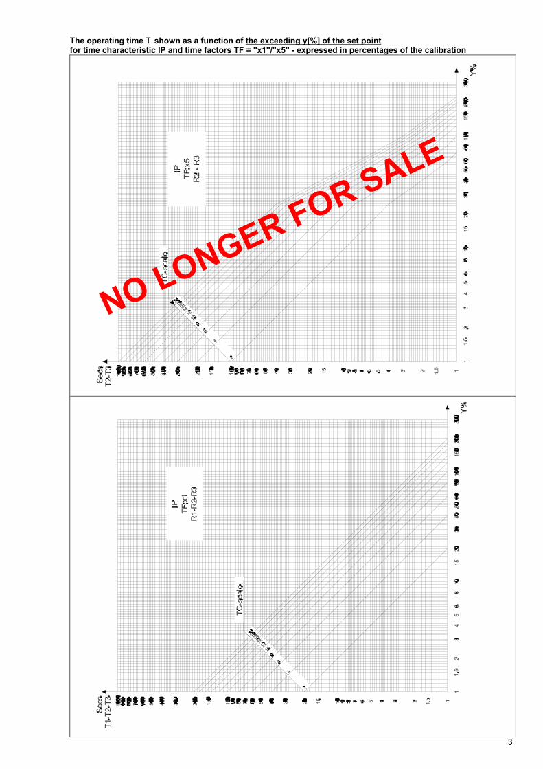
The operating time T shown as a function of the exceeding y[%] of the set point for time characteristic IP and time factors TF = "x1"/"x5" - expressed in percentages of the calibration
3
NO LONGER FOR SALE
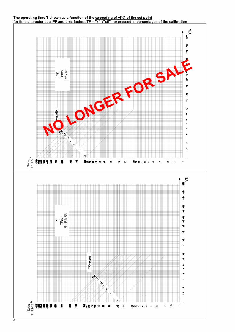
The operating time T shown as a function of the exceeding of y[%] of the set point for time characteristic IPF and time factors TF = "x1"/"x5" - expressed in percentages of the calibration
4
NO LONGER FOR SALE
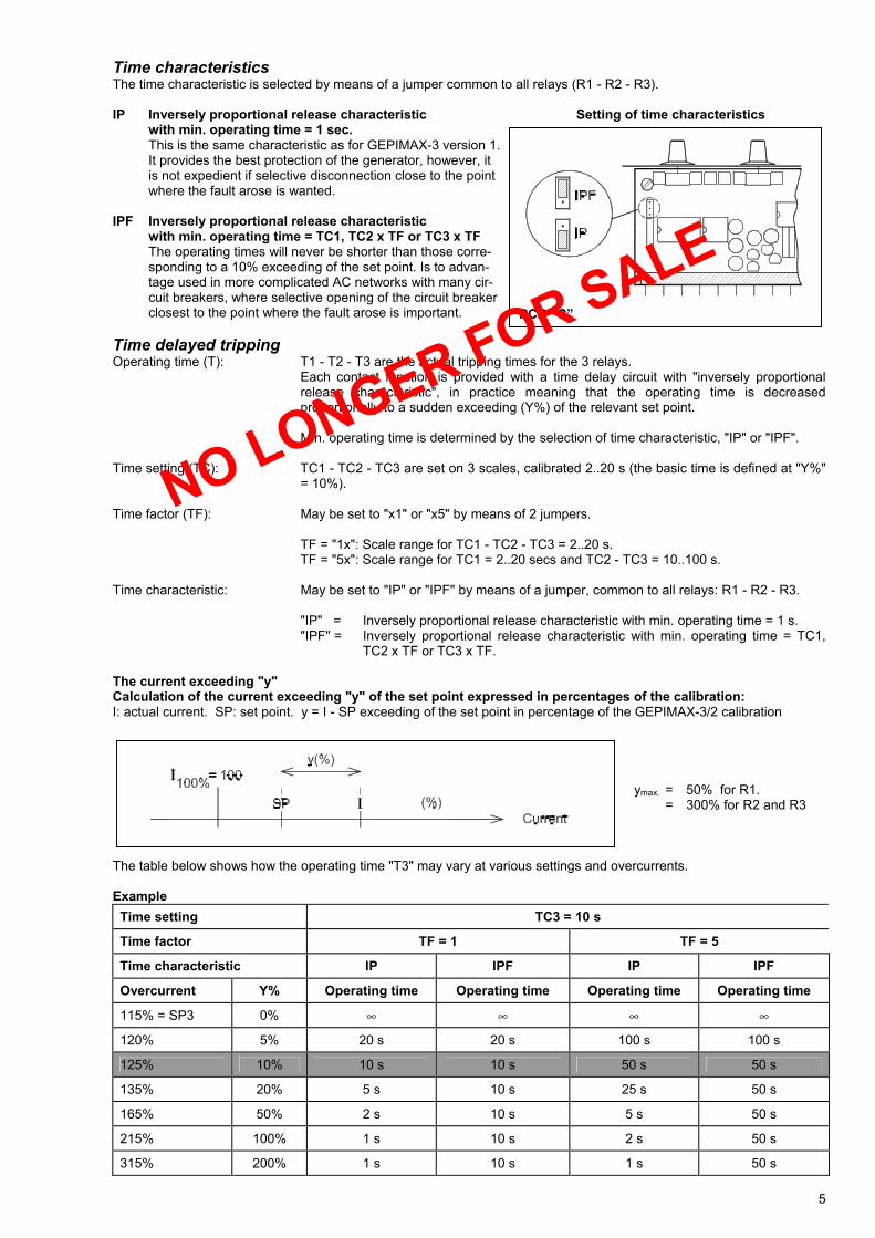
Time characteristics The time characteristic is selected by means of a jumper common to all relays (R1 - R2 - R3). IP Inversely proportional release characteristic Setting of time characteristics with min. operating time = 1 sec.
This is the same characteristic as for GEPIMAX-3 version 1. It provides the best protection of the generator, however, it is not expedient if selective disconnection close to the point where the fault arose is wanted.
IPF Inversely proportional release characteristic with min. operating time = TC1, TC2 x TF or TC3 x TF
The operating times will never be shorter than those corre- sponding to a 10% exceeding of the set point. Is to advan- tage used in more complicated AC networks with many cir- cuit breakers, where selective opening of the circuit breaker closest to the point where the fault arose is important.
Time delayed tripping Operating time (T): T1 - T2 - T3 are the actual tripping times for the 3 relays.
Each contact function is provided with a time delay circuit with "inversely proportional release characteristic", in practice meaning that the operating time is decreased proportionally to a sudden exceeding (Y%) of the relevant set point.
Min. operating time is determined by the selection of time characteristic, "IP" or "IPF".
Time setting (TC): TC1 - TC2 - TC3 are set on 3 scales, calibrated 2..20 s (the basic time is defined at "Y%"
= 10%). Time factor (TF): May be set to "x1" or "x5" by means of 2 jumpers. TF = "1x": Scale range for TC1 - TC2 - TC3 = 2..20 s.
TF = "5x": Scale range for TC1 = 2..20 secs and TC2 - TC3 = 10..100 s. Time characteristic: May be set to "IP" or "IPF" by means of a jumper, common to all relays: R1 - R2 - R3.
"IP" = Inversely proportional release characteristic with min. operating time = 1 s. "IPF" = Inversely proportional release characteristic with min. operating time = TC1,
TC2 x TF or TC3 x TF. The current exceeding "y" Calculation of the current exceeding "y" of the set point expressed in percentages of the calibration: I: actual current. SP: set point. y = I - SP exceeding of the set point in percentage of the GEPIMAX-3/2 calibration ymax. = 50% for R1. = 300% for R2 and R3 The table below shows how the operating time "T3" may vary at various settings and overcurrents. Example Time setting TC3 = 10 s
Time factor TF = 1 TF = 5
Time characteristic IP IPF IP IPF
Overcurrent Y% Operating time Operating time Operating time Operating time
115% = SP3 0% ∞ ∞ ∞ ∞
120% 5% 20 s 20 s 100 s 100 s
125% 10% 10 s 10 s 50 s 50 s
135% 20% 5 s 10 s 25 s 50 s
165% 50% 2 s 10 s 5 s 50 s
215% 100% 1 s 10 s 2 s 50 s
315% 200% 1 s 10 s 1 s 50 s
5
PCB ”C”
NO LONGER FOR SALE
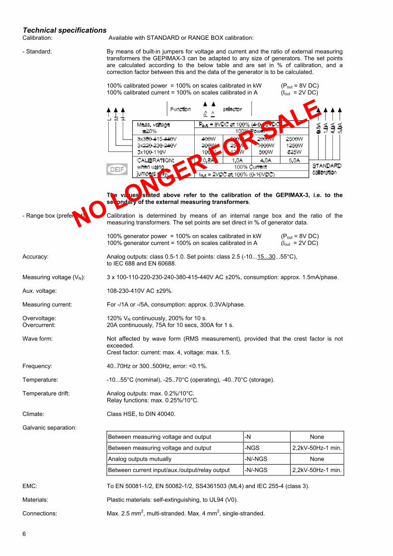
Technical specifications Calibration: Available with STANDARD or RANGE BOX calibration: - Standard: By means of built-in jumpers for voltage and current and the ratio of external measuring
transformers the GEPIMAX-3 can be adapted to any size of generators. The set points are calculated according to the below table and are set in % of calibration, and a correction factor between this and the data of the generator is to be calculated.
100% calibrated power = 100% on scales calibrated in kW (Pout = 8V DC) 100% calibrated current = 100% on scales calibrated in A (Iout = 2V DC)
The values stated above refer to the calibration of the GEPIMAX-3, i.e. to the secondary of the external measuring transformers.
- Range box (preferred): Calibration is determined by means of an internal range box and the ratio of the
measuring transformers. The set points are set direct in % of generator data. 100% generator power = 100% on scales calibrated in kW (Pout = 8V DC) 100% generator current = 100% on scales calibrated in A (Iout = 2V DC) Accuracy: Analog outputs: class 0.5-1.0. Set points: class 2.5 (-10...15...30...55°C),
to IEC 688 and EN 60688. Measuring voltage (VN): 3 x 100-110-220-230-240-380-415-440V AC ±20%, consumption: approx. 1.5mA/phase. Aux. voltage: 108-230-410V AC ±29%. Measuring current: For -/1A or -/5A, consumption: approx. 0.3VA/phase. Overvoltage: 120% VN continuously, 200% for 10 s. Overcurrent: 20A continuously, 75A for 10 secs, 300A for 1 s. Wave form: Not affected by wave form (RMS measurement), provided that the crest factor is not
exceeded. Crest factor: current: max. 4, voltage: max. 1.5.
Frequency: 40..70Hz or 300..500Hz, error: <0.1%. Temperature: -10...55°C (nominal), -25..70°C (operating), -40..70°C (storage). Temperature drift: Analog outputs: max. 0.2%/10°C.
Relay functions: max. 0.25%/10°C. Climate: Class HSE, to DIN 40040. Galvanic separation:
Between measuring voltage and output -N None
Between measuring voltage and output -NGS 2,2kV-50Hz-1 min.
Analog outputs mutually -N/-NGS None
Between current input/aux./output/relay output -N/-NGS 2,2kV-50Hz-1 min. EMC: To EN 50081-1/2, EN 50082-1/2, SS4361503 (ML4) and IEC 255-4 (class 3). Materials: Plastic materials: self-extinguishing, to UL94 (V0). Connections: Max. 2.5 mm2, multi-stranded. Max. 4 mm2, single-stranded. 6
NO LONGER FOR SALE
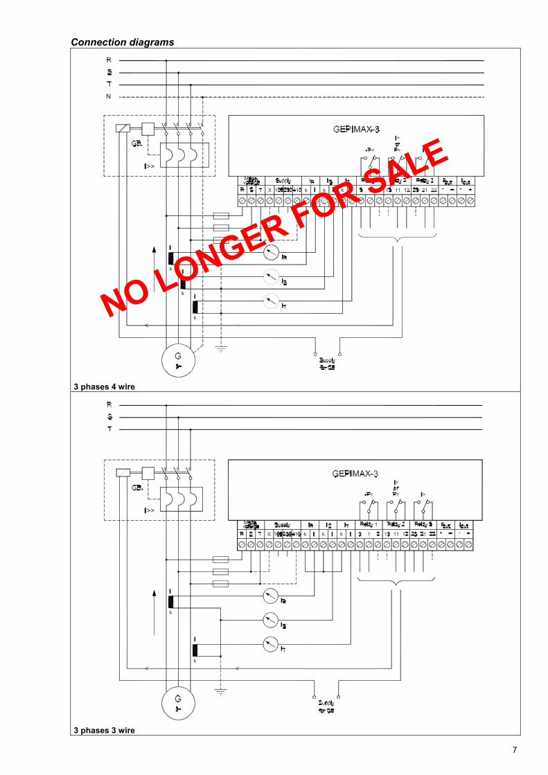
Connection diagrams 3 phases 4 wire 3 phases 3 wire
7
NO LONGER FOR SALE
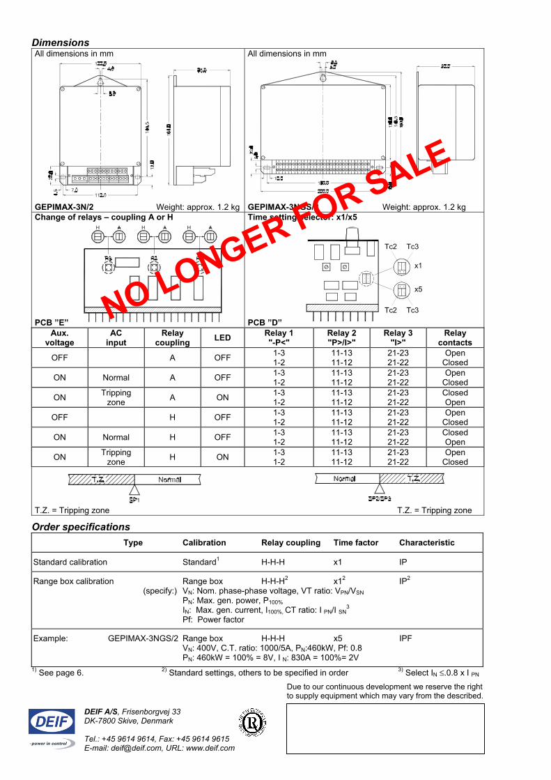
Dimensions All dimensions in mm GEPIMAX-3N/2 Weight: approx. 1.2 kg
All dimensions in mm GEPIMAX-3NGS/2 Weight: approx. 1.2 kg
Change of relays – coupling A or H PCB ”E”
Time setting selector: x1/x5 PCB ”D”
Aux. voltage
AC input
Relay coupling LED Relay 1
"-P<" Relay 2 "P>/I>"
Relay 3 "I>"
Relay contacts
OFF A OFF 1-3 1-2
11-13 11-12
21-23 21-22
Open Closed
ON Normal A OFF 1-3 1-2
11-13 11-12
21-23 21-22
Open Closed
ON Tripping zone A ON 1-3
1-2 11-13 11-12
21-23 21-22
Closed Open
OFF H OFF 1-3 1-2
11-13 11-12
21-23 21-22
Open Closed
ON Normal H OFF 1-3 1-2
11-13 11-12
21-23 21-22
Closed Open
ON Tripping zone H ON 1-3
1-2 11-13 11-12
21-23 21-22
Open Closed
T.Z. = Tripping zone T.Z. = Tripping zone
Order specifications
Type Calibration Relay coupling Time factor Characteristic
Standard calibration Standard1 H-H-H x1 IP
Range box calibration Range box H-H-H2 x12 IP2 (specify:) VN: Nom. phase-phase voltage, VT ratio: VPN/VSN PN: Max. gen. power, P100% IN: Max. gen. current, I100%, CT ratio: I PN/I SN
3 Pf: Power factor
Example: GEPIMAX-3NGS/2 Range box H-H-H x5 IPF VN: 400V, C.T. ratio: 1000/5A, PN:460kW, Pf: 0.8 PN: 460kW = 100% = 8V, I N: 830A = 100%= 2V
1) See page 6. 2) Standard settings, others to be specified in order 3) Select IN ≤.0.8 x I PN Due to our continuous development we reserve the right to supply equipment which may vary from the described.
DEIF A/S, Frisenborgvej 33 DK-7800 Skive, Denmark Tel.: +45 9614 9614, Fax: +45 9614 9615 E-mail: [email protected], URL: www.deif.com
NO LONGER FOR SALE