uartsbee v4 introduction - Чип и Дипlib.chipdip.ru/583/doc000583477.pdf · uartsbee v4...
TRANSCRIPT
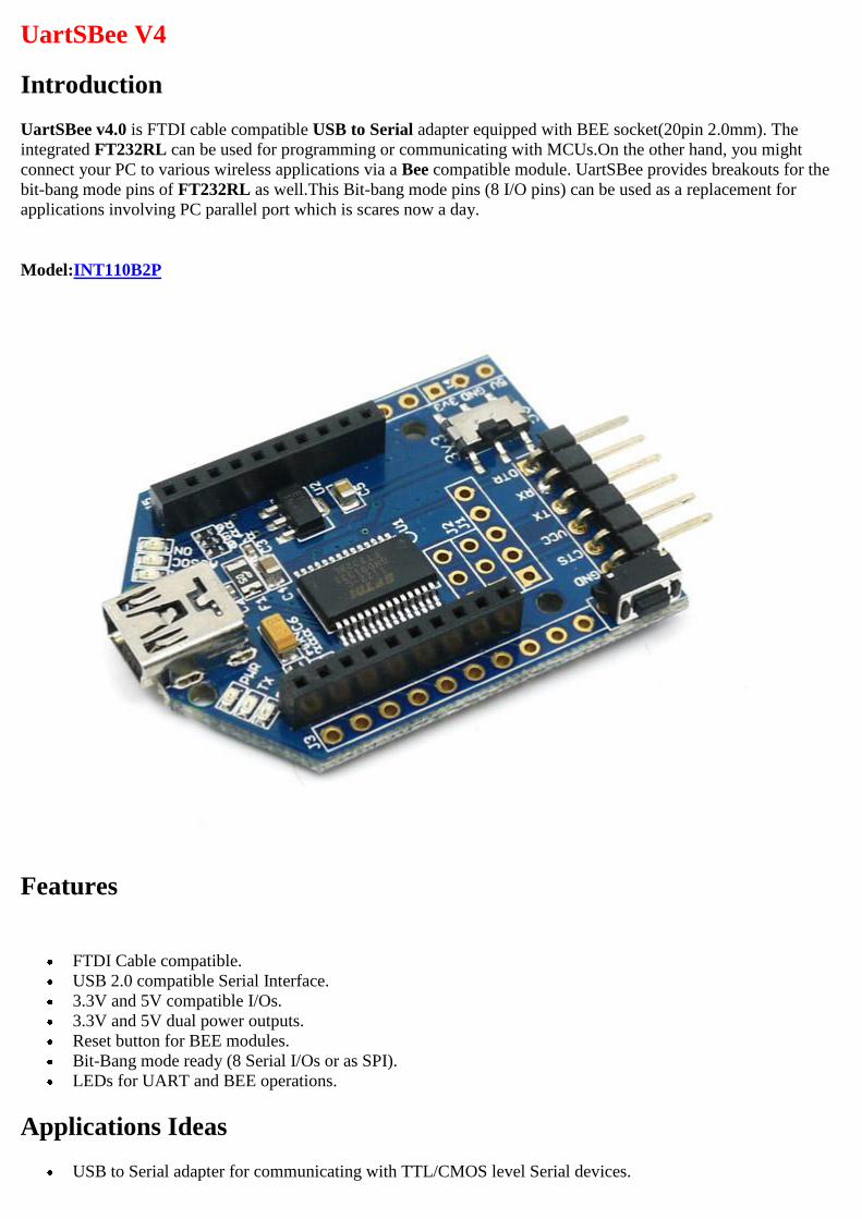
UartSBee V4
Introduction
UartSBee v4.0 is FTDI cable compatible USB to Serial adapter equipped with BEE socket(20pin 2.0mm). The
integrated FT232RL can be used for programming or communicating with MCUs.On the other hand, you might
connect your PC to various wireless applications via a Bee compatible module. UartSBee provides breakouts for the
bit-bang mode pins of FT232RL as well.This Bit-bang mode pins (8 I/O pins) can be used as a replacement for
applications involving PC parallel port which is scares now a day.
Model:INT110B2P
Features
FTDI Cable compatible.
USB 2.0 compatible Serial Interface.
3.3V and 5V compatible I/Os.
3.3V and 5V dual power outputs.
Reset button for BEE modules.
Bit-Bang mode ready (8 Serial I/Os or as SPI).
LEDs for UART and BEE operations.
Applications Ideas
USB to Serial adapter for communicating with TTL/CMOS level Serial devices.
Programmer for Arduino / Seeeduino and compatible boards.
Programmer for micro-controllers / CPLDs using ISP(in-circuit-serial-programming).
3.3V / 5V power source for a breadboard MCU applications
USB Adapter for BEE modules (for PC wireless function).
Endless possibilities as a USB based parallel device in FT232RL bit-bang mode - Known to work as AVR-
ISP, Slowspeed JTAG with OpenOCD, as I2C,
Cautions
UartSBee v3.1 provide a power selection(3.3V or 5V) toggle switch. Before connecting the board to any
other device, make sure you set the power selection switch to either 3.3V or 5V.
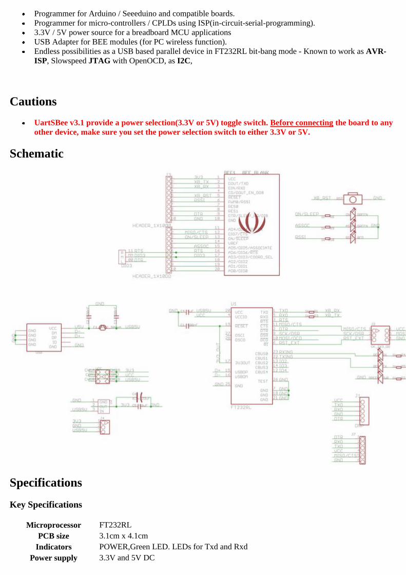
Schematic
Specifications
Key Specifications
Microprocessor FT232RL
PCB size 3.1cm x 4.1cm
Indicators POWER,Green LED. LEDs for Txd and Rxd
Power supply 3.3V and 5V DC

Interface Mini-B USB, 2.54mm pitch pin header
Adapter socket XBee compatible 2.0mm pitch female pin header
Connectivity USB
Communication Protocol UART, Bit Bang I/O, SPI
ROHS YES
Electrical Characterstics
Specification Minimum Typical Maximum Unit
Input voltage - 5 5 Vdc
Current Consumption - - 500 mA
Output voltage 3.3 - 5 Vdc
System Block Digram
A tiny reset switch is provided for reseting Bee compatible devices.
Apart from 2 x 10 Breakout for BEE compatible modules, additional pads for 2 x 10pin headers, 2 x 3 ISP
header are provided.Users can solder pin headers appropriately.
Applications
USB – Serial Port
UartSBee is commonly used as USB to Serial Port (COM port) interface. This kind of configuration can be used to
communicate with a MCU serial port or to program a MCU which support UART based ISP.
Windows
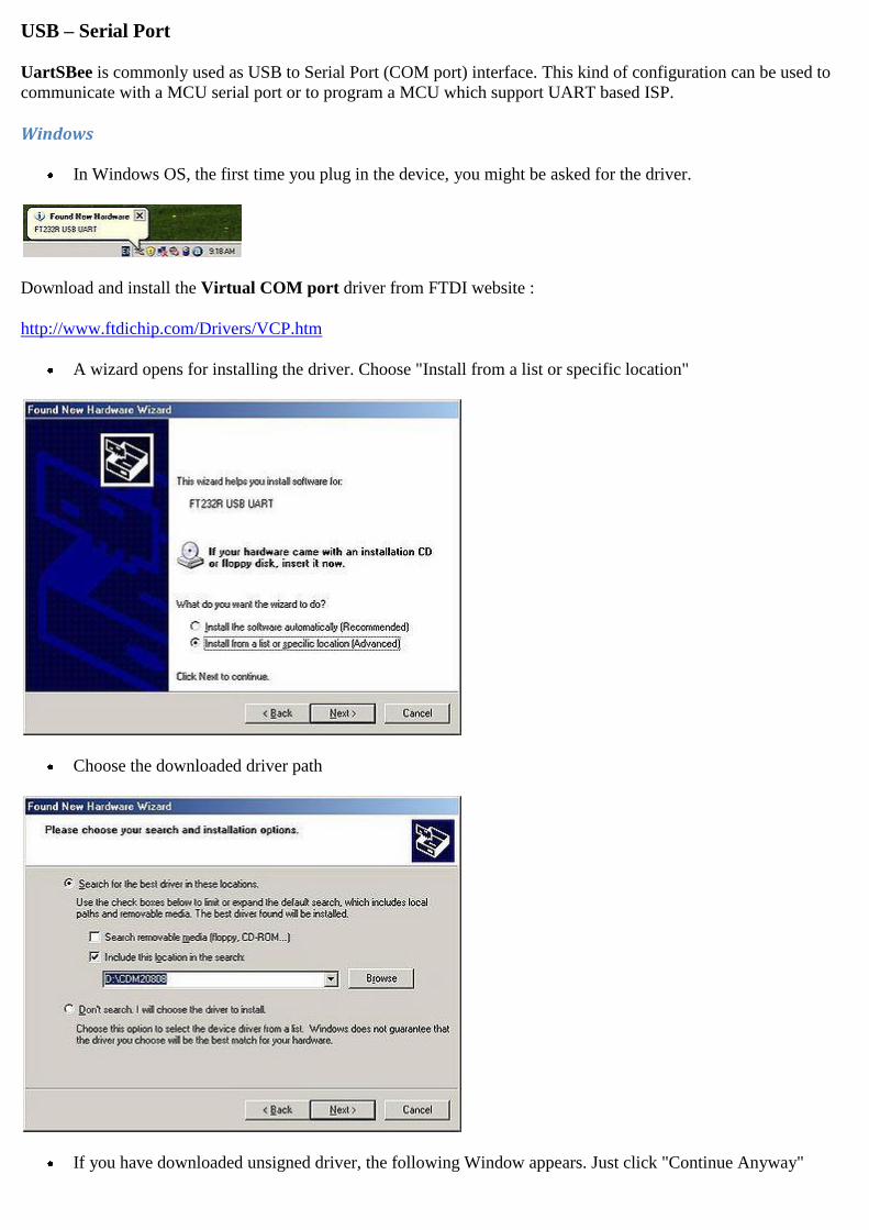
In Windows OS, the first time you plug in the device, you might be asked for the driver.
Download and install the Virtual COM port driver from FTDI website :
http://www.ftdichip.com/Drivers/VCP.htm
A wizard opens for installing the driver. Choose "Install from a list or specific location"
Choose the downloaded driver path
If you have downloaded unsigned driver, the following Window appears. Just click "Continue Anyway"

UartSBee driver is successfully installed. Windows assigns a COM port name to FT232RL like COM10,
COM11 etc... Please check the exact name in Device Manager. In this case "COM16" is assigned for
UartSBee
GNU/Linux
All modern GNU/Linux OS comes with FT232RL drivers. To check if UartSBee is detected, Issue a lsusb
command. An output similar to below should appear.
GNU/Linux assigns /dev/ttyUSB0, /dev/ttyUSB1 etc... as device name.
To verify the working of serial port connect TxD and RxD pins of UartSBee and use a terminal application like
cutecom to configure the device parameters as shown below.
Baudrate:9600, Data bits:8, Stop bits:None and no Handshake

Any character typed in terminal would be echoed back as shown.
The same functionality can be checked in Windows - Hyperterminal as well.
3.3V / 5v Power Source for MCU breadboard µCs and Programmer for µCs / CPLDs
Apart from 3.3V and 5V power outputs provided by UartSBee , the logic level of I/O pins can be selected for
5.0V TTL or 3.3V CMOS operations. In the below example a bread based board micro-controller application is
demonstrated. A LPC1343 ARM Cortex-M3 MCU is connected to UartSBee. As this is a 3.3V device, the power
toggle switch is set to 3.3V. LPC1343 can be programmed through UART. This application could be extended to any
MCU / CPLDs which support UART based flashing or SPI based flashing (Needs FT232R BitBang mode).
BreadBoard Prototyping: UartSBee v3.1 acting as as 3.3V power-supply and 3.3V UART flash programming port
for LPC1343.

Switch: 3.3V I/O Selected
Bee Module Interfacing for PC Wireless application
PC Wireless Ad-Ons
UartSBee's Bee compatible interface provided can be used to connect Bee module like XBee, Bluetooth Bee, RF
Bee, Wifi Bee, GPS Bee to PC USB. This makes Bee based PC Wireless application easier. As most of these Bee
modules support UART interface, PC programming is easy as well.
MCU Wireless Ad-Ons
This type of arrangement can be also used to interface with UART of micro-controllers (Seeeduino) .
Please refer the Bee module documentation for more information.
XBee Connected toUartSBee BluetoothBee Connected toUartSBee

BitBang Mode
An nice feature of UartSBee v3.1 compared to other FT232RL based USB-Serial devices is that all the Bit-Bang I/Os
are brought to the header pins.
Bit-Bang mode is a special feature of FT232RL in which 8 I/O lines (D0 - D7) can be used as a general purpose
bidirectional I/O lines. Three Bit-Bang modes are supported by FT232RL
Asynchronous Bit-Bang mode
Any data written to the device is clocked to the configured output pins. The rate of data transfer is configured based
on baud rate generator. In this mode any of 8 I/O lines can be configured as input or ouput.
Synchronous Bit-Bang mode
In this mode data is sent synchronously. An input is read before an output byte is sent to the device. Hence to read
input, a write operation must be performed.
CBUS Bit-Bang Mode
This is a special mode which requires reprogramming of FT232RL EEPROM. This uses signals C0 - C3.
Bit-Bang Mode of FT232RL is well documented in the application note[1]
Table: Bit-Bang I/O Mapping
UartSBee Signal BitBang I/O Signal
TxD D0
RxD D1
RTS D2
CTS D3
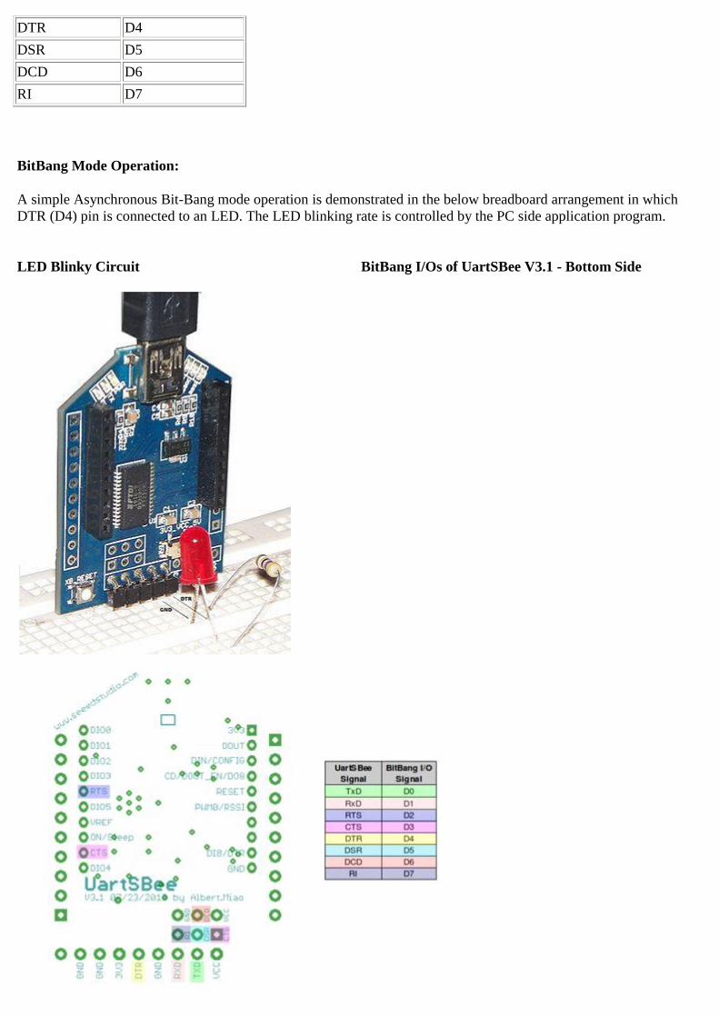
DTR D4
DSR D5
DCD D6
RI D7
BitBang Mode Operation:
A simple Asynchronous Bit-Bang mode operation is demonstrated in the below breadboard arrangement in which
DTR (D4) pin is connected to an LED. The LED blinking rate is controlled by the PC side application program.
LED Blinky Circuit BitBang I/Os of UartSBee V3.1 - Bottom Side
Bit-Bang mode requires special FTDI direct driver called D2XX. This driver needs to be installed after removing the
Virtual COM Port driver of FT232RL chip. In GNU/Linux this driver runs in kernel mode. As an alternative to
D2XX an Free Open Source driver libFTDI is available. This works in Windows, GNU/Linux and Mac OS. It runs in
user mode in GNU/Linux. Hence no need to remove the existing FT232RL driver.
libFTDI
http://www.intra2net.com/en/developer/libftdi/
libUSB libFTDI required libusb which can be downloaded from
http://www.libusb.org/
The below example code can be compiled in the similar way as that of libFTDI example files. An easy way is to copy
the contents of the below code to one of the existing example .c file and build the whole driver using
./configure
make
Code Example
/*
Blinky.C : UartSBee v3.1 (FT232RL) Bit-Bang mode - Blinky.
Circuit:
Connect DTR to Anode of LED, Connect one end of resistor to GND and other end
to Cathode of the LED
*/
#ifdef __WIN32__
#define sleep(x) Sleep(x)
#endif
// 8 bit pin mask for I/O pin
#define TXD 0x01
#define RXD 0x02
#define RTS 0x04
#define CTS 0x08
#define DTR 0x10
#define DSR 0x20
#define DCD 0x40
#define RI 0x80
#include <stdio.h>
#include <ftdi.h>
int main()
{
unsigned char ouputState = 0;
struct ftdi_context ftdic;
/* 1. Initialize ftdi device context */
ftdi_init(&ftdic);
/* 2. Open the device based of VID/PID pair */
if(ftdi_usb_open(&ftdic, 0x0403, 0x6001) < 0)
{
printf("Unable to UartSBee v3.1");
return 1;
}
/* 3. Enable Bit-Bang mode with for DTR line */
ftdi_set_bitmode(&ftdic, DTR, BITMODE_BITBANG);
/* 4. Blink LED every 1 second */
while(1) {
ouputState ^= DTR;
ftdi_write_data(&ftdic, &ouputState, 1);
sleep(1);
}
}
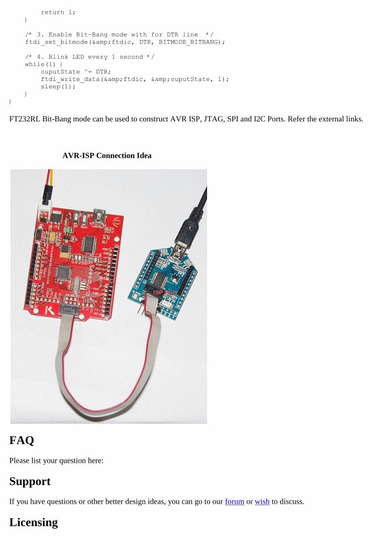
FT232RL Bit-Bang mode can be used to construct AVR ISP, JTAG, SPI and I2C Ports. Refer the external links.
AVR-ISP Connection Idea
FAQ
Please list your question here:
Support
If you have questions or other better design ideas, you can go to our forum or wish to discuss.
Licensing
This documentation is licensed under the Creative Commons Attribution-Noncommercial-Share Alike License 3.0.
Source code and libraries are licensed under GPL/LGPL, see source code files for details.
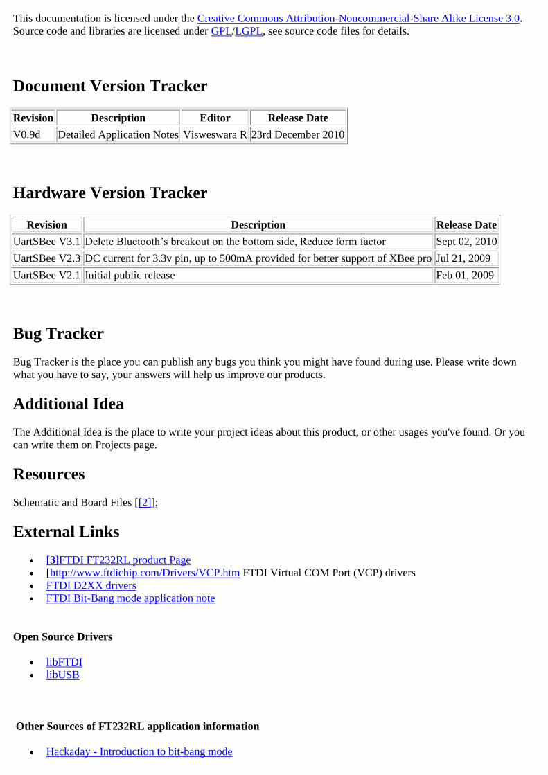
Document Version Tracker
Revision Description Editor Release Date
V0.9d Detailed Application Notes Visweswara R 23rd December 2010
Hardware Version Tracker
Revision Description Release Date
UartSBee V3.1 Delete Bluetooth’s breakout on the bottom side, Reduce form factor Sept 02, 2010
UartSBee V2.3 DC current for 3.3v pin, up to 500mA provided for better support of XBee pro Jul 21, 2009
UartSBee V2.1 Initial public release Feb 01, 2009
Bug Tracker
Bug Tracker is the place you can publish any bugs you think you might have found during use. Please write down
what you have to say, your answers will help us improve our products.
Additional Idea
The Additional Idea is the place to write your project ideas about this product, or other usages you've found. Or you
can write them on Projects page.
Resources
Schematic and Board Files [[2]];
External Links
[3]FTDI FT232RL product Page
[http://www.ftdichip.com/Drivers/VCP.htm FTDI Virtual COM Port (VCP) drivers
FTDI D2XX drivers
FTDI Bit-Bang mode application note
Open Source Drivers
libFTDI
libUSB
Other Sources of FT232RL application information
Hackaday - Introduction to bit-bang mode

FT232R JTAG implementation with OpenOCD
FT232R SPI Bitbang Mode example
Flashing Arduino with FT232R bitbang mode
See Also
Bee series
Licensing
This documentation is licensed under the Creative Commons Attribution-ShareAlike License 3.0 Source code and
libraries are licensed under GPL/LGPL, see source code files for details.