uav-aided wireless networks
TRANSCRIPT
UAV-aided Wireless Networks
Markus StrootBen Becks
David AlgarraMiguel Fontanilla
May 17, 2018
Date Performed: SS 2018Instructor: Professor Becvar
1 Introduction
With increasing use of mobile communication over the last two decades thedemand of a high bandwidth standard increased as well. The most recent andpotent development is the LTE Advanced Pro standard, an intermediate steptowards 5G. It is in the middle of development and lots of research and testing isbeing performed by various institutions right now. A few public testing networkshave been installed. However, the focus lies on the implementation of a basicnetwork containing the standards components and mobile devices. The natureof the used eNodeB is their fixed position and therefore fixed range of signalcoverage.Our goal is to provide flexible, short time range extension which can be utilizedin some specific environments. The basic idea is to offer coverage to areas thatare not covered by fixed stations or in which the cells are overloaded. Thereforewe implement an eNodeB on a small and transportable computing system. Thissystem stays in range of the base station and connects to it. It acts as an accesspoint for mobile devices and relays traffic.To achieve sufficient coverage, flexibility in positioning and deployment and afast installation of the relay we build a UAV and mount the relaying computingsystem to it. The UAV is a Hexacopter operated by a single person. Thecapabilities of modern drones, however, allow hovering in the same position viaGPS. Only start and landing is operated by a pilot while during the operationtime no piloting is needed. In further development even these steps can beautomated resulting in the only need to deploy the drone in an open field andswitching it on.The relatively short time of operation due to power shortage does not suitfor a constant operation for increased coverage. Use cases can be emergency
1
situations after disasters in regions with bad mobile network coverage. Com-munication is a crucial element of success in these situations.A second capability of this relay is increased capacity in the covered area evenif connection to a base station is possible. Use case in this scenario are eventswith many people and mobile devices.This document summarizes our approach and the realization of the UAV guidedLTE relay. In chapter 2 we describe the software configuration for the computingsystem. Chapter 3 documents the hardware configuration with components andconnections. Finally chapter 4 outlines future work to be done.
2 Communication Software Configuration
Main Communication software used is Open Air Interface [1], which allows toemulate both an LTE eNodeB as well as the LTE Evolved Packet Core (EPC).It is run over Linux, and thus, Ubuntu is used as the operating system for thecomputers used. However, due to the intensive use of CPU required by theeNodeB application, the kernel needs to be modified, to ensure that the powersaving mechanisms and CPU frequency scaling are disabled, as specified in [2].In order to run the Open Air Interface software, computers used should bepreviously configured. Three computers are used for this implementation, asshown in Figure 3. Two of these computers are desktop computers, and theyare in charge of running the EPCs and one of the eNodeBs, while the computerinstalled in the UAV is a lighweight but powerful one, in charge of running theother eNodeB and supporting the LTE fronthaul connection via an LTE dongle.The nomenclature used for this computers is listed below:
• Computer 1 for the desktop computer running the eNodeB 1
• Computer 2 for the UAV onboard computer
• Computer 3 running both EPCs
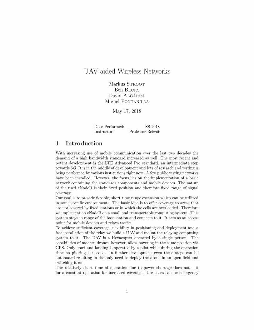
In the case of the third computer, both EPCs are running as virtual machines,so the computer will act as a gateway to the internet, and an interconnectionbetween both EPCs and the eNodeB 1. In Figure 1 the IP addressing schemeused in the implementation is shown. Computer 1 and 3 are connected to thesame private network, within the range 192.168.0.1/24, in which the router, isthe main gateway to the public internet. Each EPC has its own pool of IPaddresses, that are assigned to the the eNodeBs that are connected to it andto the UEs. This IP pool range can be modified in the EPC configuration files.The link between the USB dongle and computer 1 is handled as a point-to-pointconnection, so the addressing scheme is not relevant. Due to the existence of twoIP ranges in the same virtual machine, some changes are necessary regardingIP forwarding.The main steps to set the communication software are listed below:
a. LTE dongle configuration
2
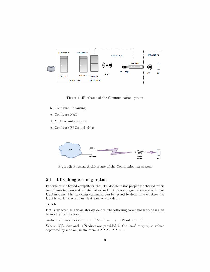
Figure 1: IP scheme of the Communication system
b. Configure IP routing
c. Configure NAT
d. MTU reconfiguration
e. Configure EPCs and eNbs
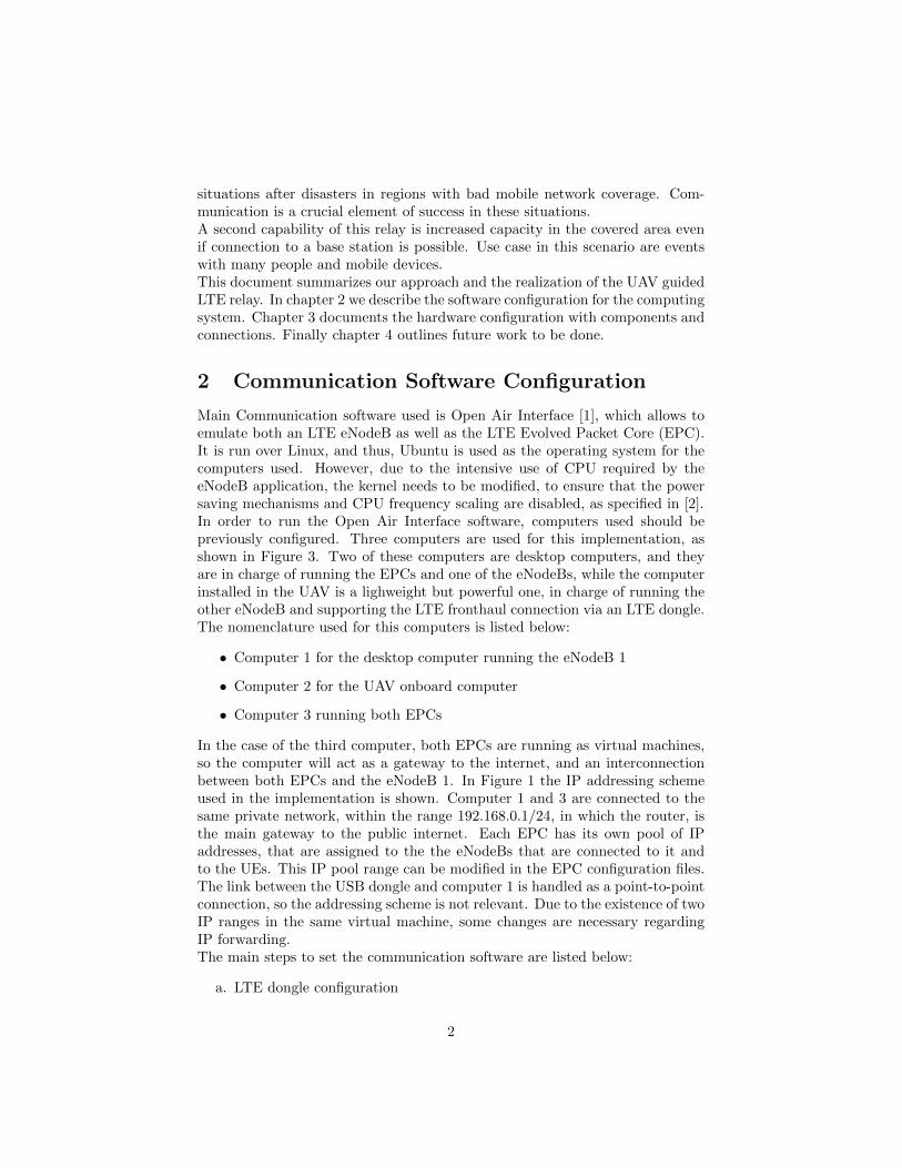
Figure 2: Physical Architecture of the Communication system
2.1 LTE dongle configuration
In some of the tested computers, the LTE dongle is not properly detected whenfirst connected, since it is detected as an USB mass storage device instead of anUSB modem. The following command can be issued to determine whether theUSB is working as a mass device or as a modem.
l su sb
If it is detected as a mass storage device, the following command is to be issuedto modify its function.
sudo usb modeswitch −v idVendor −p idProduct −J
Where idV endor and idProduct are provided in the lsusb output, as valuesseparated by a colon, in the form XXXX : XXXX.
3
Figure 3: Logical Architecture of the Communication system
2.2 Configure IP routing
Traffic handed by EPC 1 need to be properly routed when it is destinated tothe UEs of the eNodeB 2. In order to do so, the following commands are issuedin EPC 1.
ip route IP1/mask v ia IP2
Where IP1 is the destination address, IP2 is the IP of the next hop, and maskis the netmask of the destination address.
2.3 Configure NAT in EPC 2
After performing traffic captures with Wireshark it can be verified that EPC2, running in computer 3 cannot send back traffic to EPC 1, also running incomputer 3, due to the different IP addresses range. Therefore, Network AddressTranslation is required in EPC 2. By issuing the following commands, it can beeasily configured.
i p t a b l e s −t nat −F
i p t a b l e s −t nat −A PREROUTING −d IP1 −j DNAT t o −d e s t i n a t i o n IP2
i p t a b l e s −t nat −A POSTROUTING −s IP2 −j SNAT t o −source IP1
The main command flushes the NAT table, to avoid inconsistencies with pre-vious rules. IP1 is the EPC 2 address which is within the computer networkrange, whereas IP2 is the IP assigned to the EPC 2 from its IP pool range (itis in the same range as the IPs assigned to UEs).
4
2.4 MTU reconfiguration
The MTU of the links should be modified to allow the double encapsulatedpacket to be carried without problems. In order to do so, it set to differentvalues depending on the link. The command used is the following:
i f c o n f i g i n t e r f a c e mtu MTUSize .
Where MTUsize is the size in bytes. The MTU used are:
• 1400 bytes Between computer 2 and computer 1
• 2000 bytes Between computer 1 and computer 3
The MTU between the UE and the eNodeB 2 is set in the configuration files ofthe OpenAirInterface eNodeB application. It is recommended to be set to 1300bytes.
2.5 EPCs configuration
It is important to configure MMEs properly to allow communication. The SIMcard used in the LTE dongle should be associated with MME 1 whereas the onein the UE should be assoaciated with MME 2. For our tests, MME 92 is usedin EPC 1 and 94 in EPC 2. IP addresses can be easily configured in both theeNodeB and EPC configuration files.
It is recommended to use Wireshark with ping utilities in all the computersduring the configuration phase for troubleshooting and reachability tests.
3 Hardware Architecture
3.1 Drone-parts and physical configuration
The drone was intentionally chosen not to be a pre-built one, but a set. Thisensures modularity of all the parts and makes it easier to exchange and customizeeach part as needed. This said, we tried to stay as close as possible to giventutorials and suggestions in order to minimize the risk of failure. All main parts,excluding the battery, were ordered in the online shop of well-known Drone/UAVmanufacturer “Tarot” [3]. The battery was purchased in a local RC-model-shop,because of safety restrictions on the shipping of Lithium-Polymer batteries. Alisting of all Parts is shown list 1. All these parts were assembled using theprovided instruction and some tutorials we found on the internet. A picture ofthe final assembly can be seen in figure 4.
3.2 Calibration and Getting Started
3.2.1 ESC Calibration
Firstly, the ESCs have to be calibrated to the range of the throttle. This isdone by connecting each ESC in turn to the throttle output of the RC-receiver
5
Air-frame We used the Tarot Air-frame [4]. This frame is made of mostlycarbon-fiber and plastics to archive low weight and high stability. Itcomes in parts and has to be assembled, however all parts and screwsare included. The body even consists of a PCB which handles the powerdistribution.
ESCs As motor controller we used standard 40A ESCs [5]. They control themotor speed according to the servo signal they receive.
Motors They are 380KV brushless DC motors [6], which we equipped with 12inch propellers.
Flight Controller We got the NAZA-M V2 flight controller [7]. It comes witha central unit including IMU and motor controller output. Further,theyprovide a GPS-receiver, a USB-interface with status LED and a powersupply unit.
RC-Controller This controller provides remote control capabilities to the user.It is a standard RC-controller and it comes with a receiver unit, that canbe connected to the flight controller or used independently.
Communication HW The communication hardware for the LTE relay con-sists of a Intel NUC computer [8] equipped with an LTE-dongle and anda SDR.
Power Supply The voltage for the operation of the drone is provided by a6-cell 4.4 Ah lithium-polymer battery. The communication hardware ispowered by a 15 Ah high-performance powerbank.
List 1: Test
in turn, putting the controller in full throttle position and connecting everythingto the power supply. The ESC will go in calibration mode. Moving the throttlestick to the very bottom position and back up will calibrate its range into theESC.
3.2.2 IMU and Compass Calibration
Once ESCs are calibrated and everything is mounted it is necessary to calibratethe IMU inside the NAZA flight controller. This is done by the NAZA driversoftware available on their homepage [7]. The drone is placed on an even andsteady surface and start calibration mode through the software. This estimatese.g. gyroscope and accelerometer bias.The compass calibration is a bit more complicated. it can be done before theflight. The drone is started and using the RC-controller the user has to switchseveral times between manual and altitude-assisted flight mode (flight modesin list 2). The drone then enters compass calibration mode. Now it has to be
6
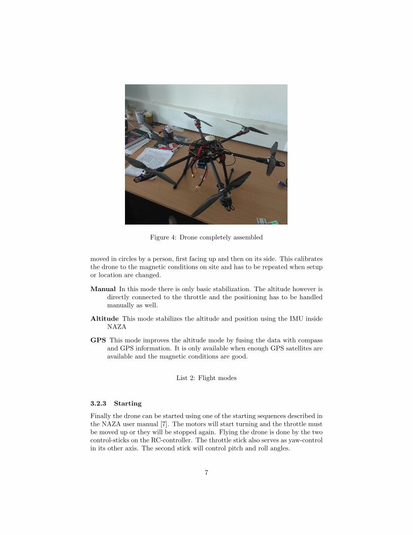
Figure 4: Drone completely assembled
moved in circles by a person, first facing up and then on its side. This calibratesthe drone to the magnetic conditions on site and has to be repeated when setupor location are changed.
Manual In this mode there is only basic stabilization. The altitude however isdirectly connected to the throttle and the positioning has to be handledmanually as well.
Altitude This mode stabilizes the altitude and position using the IMU insideNAZA
GPS This mode improves the altitude mode by fusing the data with compassand GPS information. It is only available when enough GPS satellites areavailable and the magnetic conditions are good.
List 2: Flight modes
3.2.3 Starting
Finally the drone can be started using one of the starting sequences described inthe NAZA user manual [7]. The motors will start turning and the throttle mustbe moved up or they will be stopped again. Flying the drone is done by the twocontrol-sticks on the RC-controller. The throttle stick also serves as yaw-controlin its other axis. The second stick will control pitch and roll angles.
7
4 Future Work
One of the most interesting features to be implemented is the autonomous po-sitioning of the drone, for example, based on the received signal level by theusers. To do so, a ground station is required to command the drone and com-municate with it. The only implementation compatible with Naza V2 autopilotis a proprietary one, developed by dji [9]. It provides an onboard sdk, as wellas a guidance sdk. It requires some additional hardware.On the other hand, there is an open source drone software platform calledDroneCode [10]. It offers a complete software suite for developing drone-basedapplications and services. It consists of the following elements:
• QGroundControl, a ground station
• PX4, an open source autopilot
• MAVLink, a lightweigh message marshalling library for air vehicles
• DroneCore, a cross platform API for PX4 over MAVLink
PX4 autopilot requires additional hardware too, but it is cheaper than the onerequired by the dji software. Furthermore, the recommended hardware, Pix-Hawk 4 [11], can be easily integrated with onboard computers, specifically withthe intel NUC [8]. Once the drone can be automatically positioned, differentalgorithms can be tested making use of the provided sdk.Apart from drone positioning, computational load can be reduced by integratingthe Open Air Interface RRH implementation into the intel NUC. Besides, itcould provide higher flexibility, as several RRH can be controlled an served bythe same BBU.
References
[1] Openairairinterface project. http://www.openairinterface.org/. [On-line; accessed 6-April-2018].
[2] Openair kernel main setup. https://gitlab.eurecom.fr/oai/
openairinterface5g/wikis/OpenAirKernelMainSetup. [Online; ac-cessed 6-April-2018].
[3] Tarot. Web-page of drone manufacturer. http://www.tarot-rc.com. [On-line; accessed 6-April-2018].
[4] Helipal. Shop page with airframe and other parts. http://www.helipal.
com/tarot-fy680-pro-hexacopter-frame-set.html. [Online; accessed6-April-2018].
[5] Helipal. Shop page with esc and other parts. http://www.helipal.com/
hobbywing-xrotor-40a-esc.html. [Online; accessed 6-April-2018].
8
[6] Helipal. Shop page with motor and other parts. http://www.helipal.
com/tarot-4008-high-power-brushless-motor-380kv.html. [Online;accessed 6-April-2018].
[7] DJI. Shop page with flight controller and its parts. https://www.dji.
com/naza-m-v2. [Online; accessed 6-April-2018].
[8] Intel nuc onboard computer. https://pixhawk.org/peripherals/
onboard_computers/intel_nuc. [Online; accessed 16-May-2018].
[9] Dji sdk. https://developer.dji.com/onboard-sdk/. [Online; accessed16-May-2018].
[10] Dronecode. https://www.dronecode.org/. [Online; accessed 16-May-2018].
[11] Pixhawk autopilot. https://pixhawk.org/modules/pixhawk. [Online;accessed 16-May-2018].
9