uflex katalog 2012
DESCRIPTION
Kontrollutstyr og trimplan Ratt | Hydrauliske styringer | Mekaniske styringer | Kontrollutstyr | Instrumenter | Trimplan | Rorbeslag Seilbåt | ReservedelerTRANSCRIPT

A WORLD OFMARINE
EQUIPMENT
UFLEX12

RITCHIE® - Globemaster® Skylight magnetic compasses page 34
WEMA® instruments – Silver Series page 46 - 49
®
Electro-mechanical Trim Tabs page 15 - 18
NEW
12

1
RAILBLAZA™ - Starport™ and Tracport™ moun-ting systems and accessories page 85 - 90
VICTRON®
GX Battery charger page 140
UFLEX® - Centrifugal electric pumpsUB-CE series page 71
UFLEX® - Self-priming electric pumpUSBR series page 73
WHISPER POWER®- Variable speed dieselgenerators page 163
HALYARD® - Silencing and exhaust systemspage 165 to 175
NEW12

UFLEX
ULTRAFLEX
UFLEX - Divisione energia
ULTRAFLEX CONTROL SYSTEMS
INDUSTRIA di LEIVI
UFLEX USA
MARESI LTD
®
Systems and accessories for alternative energy applications
Window and skylight remote controls.Innovative LED road signs
Mechanical remote controls in the industrial field
Manufacturing the world’s finest marine products
Trim tabs
Worldwide distribution of marine accessories
Steering and control systems for pleasure boats
1935 - 2012Ultraflex Group has 77 years of experience in manufacturing
and distributing the highest quality and most innovative products.
The Ultraflex Group affiliate Companies that design and produce widely
known equipments in the marine, industrial, architectural,
Led technology and alternative energy fields.
2
1935-2012

Quality Management SystemThe Ultraflex and Uflex Quality Management Systems are certified CISQ-
IQNet by the Italian Shipping Registry (RINA), in conformity with the UNI
EN ISO 9001 rule, certification n° 420/96.
The quality management system involves all the company resources
and processes starting from the design, in order to:
• Assure product quality to the customer
• Set up the actions to maintain and improve the quality standards
constantly
• Pursue a continuous process improvement to meet the market needs
• Maintain and verify conformity with ABYC requirements.
The Ultraflex Environmental Management System is certified
CISQ-IQNet by the Italian Shipping Registry (RINA), in conformity with
the UNI EN ISO 14001. Ultraflex certification n° EMS-1282/S.
Constantly test the products to verify their conformity with the EEC
94/25 and ABYC (American Boat and Yacht Council) requirements.
Factory in Casella
Factory in Borgo Fornari
3

RAILBLAZA™
STARPORT™ AND TRACPORT™
page 85 - 90
UFLEX®
ELECTRIC PUMPSAND BLOWERSpage 67 - 84
AFI® - GUEST®SPOTLIGHTS, HORNSWIPERSpage 91 - 98
BEP MARINE®ELETTRIC PANELSAND INSTRUMENTSpage 99 - 130
MARINCO®
SHORE POWERSYSTEMSpage 131 - 138
VICTRON ENERGY®
BATTERY CHARGERS,INVERTERS, BATTERIESpage 139 - 150
MERMAID®
MARINE AIRCONDITIONING SYSTEMS
page 151 - 154
WHISPER POWER®
MARINE GENERATOR
page 155 - 164
HALYARD® - WAVE®SILENCER, EXHAUSTSYSTEMSpage 165 - 176
UFLEX®
ENERGY EQUIPMENT
page 177 - 186
ULTRAFLEX® - UFLEX®
DISPLAY,MARKETING ITEMS
page 187 - 188
The descriptions and guidelines shown in this catalogshould be used as general reference only. For any furtherinformation please contact our Technical Service.
4
INDICE
UCS®HATCH LIFTERS
page 5 to 8
UFLEX®
GAS SPRINGS
page 9 to 14
UFLEX®
ELECTRO-MECHANICALTRIM TABS
page 15 to 18
INSTATRIM®
HYDRAULIC TRIM TABS
page 19 to 22
RITCHIE®MAGNETIC COMPASSES
page 23 to 34
UFLEX® - WEMA®
MARINE INSTRUMENTS
page 35 to 50
SHURFLO®
PUMPS, BILGE PUMPS,BLOWERS, SPRAYERSpage 51 to 60
REVERSO®
OIL CHANGESYSTEMSpage 61 to 66

ULTRAFLEX CONTROL SYSTEMS S.r.l.
®
With the kind cooperation of Gobbi S.p.A. and Sessa Marine S.p.A.
5
HATCH LIFTERS
6
HATCH LIFTERS
A
Ø
42(1.65”)
27.5(1.06”)
27.5(1.06”)
Ø 6.5
Ø 4
8 1.
9”
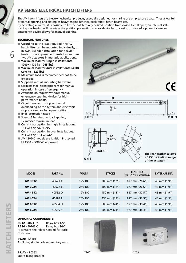
MODEL PART No. VOLTS STROKE LENGTH A(FULL CLOSED ACTUATOR)
EXTERNAL DIA.
The AV hatch lifters are electromechanical products, especially designed for marine use on pleasure boats. They allow fullor partial opening and closing of heavy engine hatches, peak tanks, hatch beams etc. By activating a switch, it is possible to lift the hatch to any desired position from closed to full open; an internal self-locking mechanism will maintain the position preventing any accidental hatch closing. In case of a power failure anemergency device allows for manual opening.
AV SERIES ELECTRICAL HATCH LIFTERS
AV 3012 40671 C
40582 D
40584 H 12V DC
12V DC
12V DC
AV 4512
AV 6012
AV 3024 40672 E
40583 F
40585 K 24V DC
24V DC
24V DC
AV 4524
AV 6024
TECHNICAL FEATURES� According to the load required, the AVhatch lifter can be mounted individually, orin twin cylinder installation for heavierloads. It is also possible to install more thentwo AV actuators in multiple applications.
� Maximum load for single installations:1200N (120 kg - 265 lbs)
� Maximum load for dual installations: 2400N(240 kg - 529 lbs)
� Maximum load is recommended not to beexceeded.
� Supplied with all mounting hardware.� Stainless steel telescopic ram for manualoperation in case of emergency.
� Available on request without manualemergency opening device for highperformance boats.
� Circuit breaker to stop accidentaloverloading of the system and electronicstop at closed or full open position.
� IP 65 protection rated� Speed: 25mm/sec no load applied, 17 mm/sec maximum load
� Current absorption in single installations:10A at 12V, 5A at 24V
� Current absorption in dual installations:20A at 12V, 10A at 24V
� AV 12VDC models are Ignition Protected.UL1500 - ISO8846 approved.
BRACKET
OPTIONAL COMPONENTS:
RB12 - 40738 Y Relay box 12VRB24 - 40742 C Relay box 24VIt contains the relays needed for cyclerevertion.
SW20 - 61101 T 1 x 3 way single pole momentary switch
BR/AV - 80382 ISpare fixing bracket
RB12SW20
48 mm (1.9”)600 mm (24”) 977 mm (38.4”)
450 mm (18”) 827 mm (32.5”) 48 mm (1.9”)
300 mm (12”) 677 mm (26.6”) 48 mm (1.9”)
600 mm (24”) 977 mm (38.4”) 48 mm (1.9”)
827 mm (32.5”)450 mm (18”) 48 mm (1.9”)
300 mm (12”) 677 mm (26.6”) 48 mm (1.9”)
The rear bracket allowsa 125° oscillation rangeof the actuator

7
HATCH LIFTERS
210.8”
421.6”
572.2”
14,50.6”
14,50.6”
150.6”
6,50.2”
6,50.2”
20 0.7”
7,
50.
3”
30 1.2”
7,5 0.3”
210.8”
Ø 3
4 1.
3”
A
MODEL PART No. VOLTS STROKE LENGTH A(FULL CLOSED ACTUATOR)
EXTERNAL DIA.
SW20
OPTIONAL COMPONENTS:SW20 - 61101 T1 x 3 way single pole momentary switch
BR/UL - 35697 P Spare fixing bracket
ULYSSES 1812 40924 Q
40925 R 12V DC
12V DC
ULYSSES 3012
ULYSSES 1824 40926 S
40927 T 24V DC
24V DC
ULYSSES 3024
TECHNICAL FEATURES� Single installation only� Pull and push maximum load: 650N(65 kg - 144 lbs)
� Pull and push maximum load isrecommended not to be exceeded.
� Supplied with all mounting hardware.� Aluminium ram.� Circuit breaker to stop accidentaloverloading of the system and electronicstop at closed or full open position.
� IP 65 protection rated� Speed:12V model:- 5 mm/sec no load applied- 4 mm/sec maximum load 24V model:- 8 mm/sec no load applied- 6 mm/sec maximum load
� Current absorption: 2A at 12V, 1A at 24V
Highest installation flexibility: 180°oscillation range
ULYSSES SERIESELECTRICALLINEAR ACTUATORS
300 mm (12”) 635 mm (25.0”) 34 mm (1.3”)
180 mm (7”) 515 mm (20.3”) 34 mm (1.3”)
635 mm (25.0”)300 mm (12”) 34 mm (1.3”)
180 mm (7”) 515 mm (20.3”) 34 mm (1.3”)

8
HATCH LIFTERS
Fig. 1 Fig. 2
Fig. 3 Fig. 4
COMPONENTS DESCRIPTIONAV Series Hatch Lifters• nº 1 AV actuator for single installation (Fig.1)• nº 2 AV actuators for dual installation (Fig.2) • External diameter: 1.9” (48 mm)• Length at closed position:14.8” (377 mm)+ stroke
• Maximum oscillation range: 125°
ULYSSES Series actuators• nº 1 Ulysses actuator (Fig.1)no dual installation
• External diameter: 1.3” (34 mm) • Length at closed position:12.1” (308 mm)+ stroke
• Maximum oscillation range: 180°
Power supply cable:• AV and ULYSSES actuators are suppliedwith 5 ft (1,5 m) of electrical cable
• Warning: in case of longer cable lengthrequired, do not substitute the existingharness, but make a junction following theinstructions supplied with the product.
Two way push-button with central offposition (optional)
Fuse (not supplied)
Battery (not supplied)
INSTALLATION• The following equation will help you tocalculate the maximum strength (Fmax)required from the hatch lifter to open yourhatch, knowing the dimensions and weightof the hatch and the position of themounting brackets.
Fmax = P x d x L2 b a
P = weight of the hatch in Newtonc, a, b = dimensions in metres indicated inFig. 3 and Fig. 4L = hatch lifter length when in closed position
Maximum load (Fmax):• AV Series actuators:1200 N (120 kg - 265 lbs) single installation,pushing only2400 N (240 kg - 530 lbs) dual installationpushing onlyNote: when the load exceeds 2400 N (240 kg- 530 lbs), it is possible to install more then two AV actuators
• ULYSSES actuators:650 N (65 kg - 144 lbs) single installationonly, both pull and push
AV ANDULYSSESSERIESELECTRICALHATCHLIFTERS
AV Actuator
Relay Box(optional)
Battery(not supplied)
Switch(optional)
AV Actuator
Relay Box(optional)
Battery(not supplied)
Switch(optional)
9
GAS SPRINGS

10
GAS SPRINGSGas springs are pneumatic force accumulators mainly used to lift, hold open and smoothly lowerhatches, covers, lids and doors. A gas spring, not equipped with a lock device, functions asfollows: the pressure of the compressed nitrogen gas contained in a tube provides the extensionforce of the spring as the result of the difference between the internal tube pressure and theatmospheric pressure. The gas flows from the highest to the lowest pressure compartment of thetube through a self-cleaning orifice in the piston rod causing the spring rod to telescope out ofthe pressure tube. Each tube incorporates a small quantity of oil that provides lubrication of the seals and of thepiston rod and, at the same time, a damping medium to control the opening speed of the coveror hatch.
UFLEX GASSPRINGS
INSTALLATION Ideal damping conditions are obtained when the spring gas is mounted with an angle of 30° fromthe vertical axis with the piston rod turned towards the hinge point: this proper installationprovides optimal performance and appropriate oil damping operation. If your application allows for quite large opening angles, a pointing up piston rod mounting maybe more appropriate, especially if the opening operation includes the passage of the rod fromthe horizontal position. When the spring rotates from B to C, the oil leaks into the gas throughthe orifice in the piston rod; the residual quantity of oil that remains between rod and conductorsprovides appropriate spent travel damping. With the piston rod pointing down and the spring in closed position, the oil is almost all leakedinto the gas through the holes and the residual quantity of oil remained between internal surfaceand piston head is not sufficient to provide a good spent travel damping.
WARNING � The rod surface should be protected against physical or chemical damages. � Lateral loads should be carefully avoided. � Attachment pivots should be well aligned. � Springs should be mounted according to previous installation instructions ensuring correctorientation.
� Tensile forces exceeding the output force as indicated for each single spring should beavoided.
� Working temperature – 30 ° C and + 80 °C.
TESTSTROKE
C
B
A
FAST
SLOW
CORRECT INCORRECT
C
B
A

11
GAS SPRINGS
Nitro-protected steel rod and marinecorrosion resistant black painted cylinder
END FITTINGS
APPLICATIONS Uflex provides gas springs in a variety of pressures to suit various installation needs, neverthelessit is the customer who decides which is the most convenient selection for a specific application.For more detailed information, please contact our Technical Service.
PACKAGING UFLEX gas springs are supplied in OEM or in Aftermarket packaging. Please specify when ordering.
TYPE 1Welded Eyelet
TYPE 2 Welded Eyelet
TYPE 3Threaded Eyelet
BLACKPAINTED GASSPRINGS
NOTE: The total length is measured from center pivot line to end fitting at fully extended spring.Further lengths, strokes and output forces available on request (20 pieces each size minimum order)
STROKE
L total ±2
Ø 8 (0.3”)
Ø 18,5
(0.7”)
MODEL
U95-5U95-10U95-20
257 (10.1)257 (10.1)257 (10.1)
95 (3.7)95 (3.7)95 (3.7)
5 (11.0)10 (22.0)20 (44.0)
8 (0.3)8 (0.3)8 (0.3)
64412 L64413 N64414 R
1 21 21 2
U140-10U140-20U140-30
365 (14.4)365 (14.4)365 (14.4)
142 (5.6)142 (5.6)142 (5.6)
10 (22.0)20 (44.0)30 (66.1)
8 (0.3)8 (0.3)8 (0.3)
64415 T64416 V64417 X
1 11 11 1
U235-10U235-20U235-30U235-40
550 (21.6)550 (21.6)550 (21.6)550 (21.6)
234 (9.2)234 (9.2)234 (9.2)234 (9.2)
10 (22.0)20 (44.0)30 (66.1)40 (88.1)
8 (0.3)8 (0.3)8 (0.3)8 (0.3)
64418 Z64419 B64420 K64421 M
1 11 11 11 1
U260-20U260-30U260-40
600 (23.6)600 (23.6)600 (23.6)
262 (10.3)262 (10.3)262 (10.3)
20 (44.0)30 (66.1)40 (88.1)
8 (0.3)8 (0.3)8 (0.3)
64422 P64423 S64424 U
2 32 32 3
TOTAL LENGTH
mm (“)
STROKE
mm (“)
OUTPUTFORCE
Kg (lbs)
RODDIA.
mm (“)
END FITTING
SIDE A SIDE BTYPE TYPE
AFTERMARKETPACKAGING
Part No.
64312 G64313 J64314 L
64315 N64316 R64317 T
64318 V64319 X64320 F64321 H
64322 K64323 M64324 P
OEMPACKAGING
Part No.
U300-30U300-40U300-50
683 (26.8)683 (26.8)683 (26.8)
300 (11.8)300 (11.8)300 (11.8)
30 (66.1)40 (88.1)50 (110.2)
10 (0.4)10 (0.4)10 (0.4)
65300 E65301 G65302 J
2 22 22 2
65297 V65298 X65299 Z

12
GAS SPRINGS
Nitro-protected steel rod and marinecorrosion resistant black paintedcylinder. Thermoplastic ball bearing endfittings to be threaded on.
END FITTINGS
APPLICATIONS Uflex provides gas springs in a variety of pressures to suit various installation needs, neverthelessit is the customer who decides which is the most convenient selection for a specific application.For more detailed information, please contact our Technical Service.
PACKAGING UFLEX gas springs are supplied in OEM or in Aftermarket packaging. Please specify when ordering.
BLACKPAINTEDGAS SPRINGSUB SERIES
NOTE: The total length is measured from center pivot line to end fitting at fully extended spring.Further lengths, strokes and output forces available on request (20 pieces each size minimum order)
NOTE: End fittings to beordered separatelyKit XB01 - 66510 K
STROKE
M6 M6
L total ±2
Ø 8 (0.3”)
Ø 18,5
(0.7”)
MODEL
UB100-5UB100-10UB100-20
275 (10.8)275 (10.8)275 (10.8)
100 (3.9)100 (3.9)100 (3.9)
5 (11.0)10 (22.0)20 (44.0)
6 (0.2)6 (0.2)6 (0.2)
66443 J66444 L66445 N
UB120-10UB120-20UB120-30
315 (12.4)315 (12.4)315 (12.4)
120 (4.7)120 (4.7)120 (4.7)
10 (22.0)20 (44.0)30 (66.1)
6 (0.2)6 (0.2)6 (0.2)
66446 R 66447 T 66448V
UB150-10UB150-20UB150-30
375 (14.7)375 (14.7)375 (14.7)
150 (5.9)150 (5.9)150 (5.9)
10 (22.0)20 (44.0)30 (66.1)
6 (0.2)6 (0.2)6 (0.2)
66449 X 66450 F 66451 H
UB180-10UB180-20UB180-30
445 (17.5)445 (17.5)445 (17.5)
180 (7.0)180 (7.0)180 (7.0)
10 (22.0)20 (44.0)30 (66.1)
8 (0.3)8 (0.3)8 (0.3)
66452 K 66453 M66454 P
TOTAL LENGTH
mm (“)
STROKE
mm (“)
OUTPUTFORCE
kg (lbs)
RODDIA.
mm (“)
AFTERMARKETPACKAGING
Part No.
66420 W66421 Y 66422 A
66423 C 66424 E66425 G
UB250-20UB250-30UB250-40
585 (23.0)585 (23.0)585 (23.0)
250 (9.8)250 (9.8)250 (9.8)
20 (44.0)30 (66.1)40 (88.1)
8 (0.3)8 (0.3)8 (0.3)
66459 A66460 J 66461 L
66437 P 66438 S 66439 U
UB300-30UB300-40UB300-50
700 (27.5)700 (27.5)700 (27.5)
300 (11.8)300 (11.8)300 (11.8)
30 (66.1)40 (88.1)50 (110.2)
10 (0.4)10 (0.4)10 (0.4)
66462 N66463 R 66464 T
66440 C66441 E 66442 G
66426 J66427 L 66428 N
66429 R 66430 Z66431 B
OEMPACKAGING
Part No.
UB220-10UB220-20UB220-30UB220-40
525 (20.6)525 (20.6)525 (20.6)525 (20.6)
220 (8.6)220 (8.6)220 (8.6)220 (8.6)
10 (22.0)20 (44.0)30 (66.1)40 (88.1)
8 (0.3)8 (0.3)8 (0.3)8 (0.3)
66455 S 66456 U 66457 W 66458 Y
66432 D 66433 F 66434 H 66436 M
18 mm
Kit KB01 - 66510 X: 2 ball bearing endfittings to be threaded on the gas spring
KB01

13
GAS SPRINGS
NOTE: End fittings to beordered separately:Kit KSS01 - 66514 F(ball-joint)orKit KSS02 - 66512 B(clevis)
STROKE
M6 M6
L total ±2
Ø 8 (0.3”)
Ø 18,5
(0.7”)
NOTE: The total length is measured from center pivot line to end fitting at fully extended spring.Further lengths, strokes and output forces available on request (20 pieces each size minimum order)
MODEL
USS100-5USS100-10USS100-20
275 (10.8)275 (10.8)275 (10.8)
100 (3.9)100 (3.9)100 (3.9)
5 (11.0)10 (22.0)20 (44.0)
6 (0.2)6 (0.2)6 (0.2)
66487 F 66488 H 66489 K
USS120-10USS120-20USS120-30
315 (12.4)315 (12.4)315 (12.4)
120 (4.7)120 (4.7)120 (4.7)
10 (22.0)20 (44.0)30 (66.1)
6 (0.2)6 (0.2)6 (0.2)
66490 U 66491 W 66492 Y
USS150-10USS150-20USS150-30
375 (14.7)375 (14.7)375 (14.7)
150 (5.9)150 (5.9)150 (5.9)
10 (22.0)20 (44.0)30 (66.1)
6 (0.2)6 (0.2)6 (0.2)
66493 A 66494 C66495 E
USS180-10USS180-20USS180-30
445 (17.5)445 (17.5)445 (17.5)
180 (7.0)180 (7.0)180 (7.0)
10 (22.0)20 (44.0)30 (66.1)
8 (0.3)8 (0.3)8 (0.3)
66496 G 66497 J66498 L
TOTAL LENGTH
mm (“)
STROKE
mm (“)
OUTPUTFORCE
kg (lbs)
RODDIA.
mm (“)
AFTERMARKETPACKAGING
Part No.
66465 V 66466 X66467 Z
66468 B 66469 D 66470 M
USS250-20USS250-30USS250-40
585 (23.0)585 (23.0)585 (23.0)
250 (9.8)250 (9.8)250 (9.8)
20 (44.0)30 (66.1)40 (88.1)
8 (0.3)8 (0.3)8 (0.3)
66503 A 66504 C 66505 E
66481 T 66482 V66483 X
USS300-30USS300-40USS300-50
700 (27.5)700 (27.5)700 (27.5)
300 (11.8)300 (11.8)300 (11.8)
30 (66.1)40 (88.1)50 (110.2)
10 (0.4)10 (0.4)10 (0.4)
66506 G 66507 J 66508 L
66484 Z 66485 B66486 D
66471 P 66472 S 66473 U
66474 W66475 Y66476 A
OEMPACKAGING
Part No.
USS220-10USS220-20USS220-30USS220-40
525 (20.6)525 (20.6)525 (20.6)525 (20.6)
220 (8.6)220 (8.6)220 (8.6)220 (8.6)
10 (22.0)20 (44.0)30 (66.1)40 (88.1)
8 (0.3)8 (0.3)8 (0.3)8 (0.3)
66499 N 66500 U66501 W 66502 Y
66477 C 66478 E66479 G 66480 R
AISI 316 stailess steel rod, cylinder andthreaded end fittingsEnd fittings to be ordered separately
APPLICATIONS Uflex provides gas springs in a variety of pressures to suit various installation needs, neverthelessit is the customer who decides which is the most convenient selection for a specific application.For more detailed information, please contact our Technical Service.
END FITTINGS Kit KSS01 - 66514 F: 2 stainless steel ballbearing end fittings to be threaded on the gasspringKit KSS02 - 66512 B: 2 stainless steel eyeletend fittings to be threaded on the gas spring
PACKAGING UFLEX gas springs are supplied in OEM or in Aftermarket packaging. Please specify when ordering.
STAINLESSSTEELGAS SPRINGS USS SERIES
19 mm 22 mmKSS01 KSS02

14
GAS SPRINGS
12-0
.5”
3-0.1”
50-1.9” 7.5-
0.3“ 37
.6-1
.5”
33-1
.3”
50-1.9” 3-0.1”
37-1
.4”
8-0.
3”
25.2
-1,0
”
33-1
.3”
50-1.9” 3-0.1”
37-1
.4”
8-0.
3”
25.2
-1,0
”
12-0
.5”
3-0.1”
50-1.9” 7.5-
0.3“ 37
.6-1
.5”
33-1
.3”
50-1.9” 3-0.1”
37-1
.4”
8-0.
3”
25.2
-1,0
”
33-1
.3”
50-1.9” 3-0.1”
37-1
.4”
8-0.
3”
25.2
-1,0
”
BLACK THERMOPLASTIC BRACKETS WITH ZINC PLATEDSTEEL STUDS
SP 10 - 64325 S
SP 11 - 64326 U
SP 10
SP 11
POLISHED STAINLESS STEEL BRACKETSAND STUDS TO CARRY BALL BEARINGEND FITTINGS
Flat bracket:SB 10 - 66540 G
Square bent bracket with forwardattachment point:SB 11 - 66541 J
Square bent bracket with reverseattachment point:SB 12 - 66542 L
GAS SPRINGMOUNTING BRACKETS
POLISHED STAINLESS STEELBRACKETS AND STUDS
Flat bracket:SI 20 - 64327 WSSN 20 - 65289 W - With self-locking nuts
Square bent bracket with forwardattachment point:SI 21 - 64328 YSSN 21 - 65290 E - With self-locking nuts
Square bent bracket with reverseattachment point:SI 22 - 64329 ASSN 22 - 65291 G - With self-locking nuts
SI 20/SSN 20
SI 21/SSN 21
SI 22/SSN 22
SB10
SB11
SB12
SI 20
SI 21
SI 22
SSN 20
SSN 21
SSN 22
SB10
SB11
SB12

15
ELECTROMECHANICAL TRIM TABS
Manufactured By MARESI LTDan ULTRAFLEX GROUP Company
®

16
ELECTROMECHANICAL TRIM TABS
UFLEX MT ELECTROMECHANICAL TRIM TAB SYSTEMS
ONE ACTUATOR PER TAB COMPLETE SET:
� 1 pair of stainless steel tabs. Tabs are sold separately:selected model to be specified when ordering
� 1 pair of electromechanical actuators complete withconnection brackets (white or black version)
� 1 control unit Easyjoy (joystick) with wiring harnessincluded
TWIN ACTUATOR PER TAB COMPLETE SET:
� 1 pair of stainless steel tabs. Tabs are sold separately:selected model to be specified when ordering
� 2 pair of electromechanical actuators complete withconnection brackets (white or black version)
� 1 control unit Easyjoy (joystick) with wiring harnessincluded
Improve fuel economy and passenger comfort with Uflex electromechanical trim tabs. Featuring electropolished stainlesssteel planes and low consumption, high speed, composite actuators, these tabs are built to last in the most demandingsea conditions. Uflex trim tabs have been specifically designed for easy installation using a quick connect bracket-actuator, requiringonly one small hole per tab through the transom. The patented transom mounting bracket encapsulates the wiring toensure protection against any wiring damage.
Uflex MT trim tabs are available in 2 versions:
MTW systems with white actuators and brackets
MTB systems with black actuators and brackets
These recommendationsshould be used as a ge-neral reference only.Final selection should bemade with the assistan-ce of a qualified insta-llation technician.For any further informa-tion please contact ourThecnical Service
FEATURES� Operating system with hardened steelballscrew, suitable to withstand high pushloads.
� EASYJOY: prompt and easy control with theinnovative use of a Joystick (PATENTED)
� AUTO LINE-UP: automatic flap re-alignmentfunction
� Completely sealed thermoplastic resin tabactuators: maximum protection guaranteedby dual seals and a rubber bellow(PATENTED)
� Snap-in system (PATENTED) with protectedharness for an easy installation
� Stainless steel rod and tabs� The innovative profile of the tabs increasesthe efficiency of the system
� The top surface of the tabs is polished to givehigher resistance to marine environment
� System requires no maintenance� Voltage:12V DC� Actuator total length (full closed): 11.8” (301 mm)
� Stroke: 2.25” (57 mm)� Waterproof: IP68 protection
14' - 18'
16' - 25'
BOATLENGTH
4,5 - 5,5
5,0 - 8,0
BOAT LENGTH(m)
9" x 9"
12" x 9"
TAB SIZE(length x width)
22,8 x 22,8
30,5 x 22,8
TAB SIZE (cm)
18' - 30'
26' - 36'
5,5 - 9,0
8,0 - 11,0
12" x 12"
18" x 12"
30,5 x 30,5
45,7 x 30,5
MT
SNAP-IN

17
ELECTROMECHANICAL TRIM TABS
TAB WEIGHT
EASYJOY 41849 ZCompact control unit with Joystick (PATENTED). Auto line-up function included (automatic flapre-alignment).Wiring harness included.
� 70 mm (2.76”) hole size
CONTROL UNIT
EASYJOY
EASYJOY - Dimensions
AW12
AB12
TABS
Actuator - Dimensions
COMPONENTSAND SPARE PARTS
AW12
MODEL
41838 U
PART No.
Attuatore e staffe bianchi 12 VDC
DESCRIPTION
AB12 41842 J Attuatore e staffe neri 12 VDC
P99 41844 N Coppia pale inox 9” x 9”
P912 41845 R Coppia pale inox 9” x 12”
P1212 41846 T Coppia pale inox 12” x 12”
P1218 41847V Coppia pale inox 12” x 18”
EASYJOY 41849 Z Joystick
MODEL WEIGHT PER PAIR KG (LBS)
P99 2.8 kg (6.2 lbs)
P912 3.6 kg. (7.9 lbs)
P1212 4.6 kg. (10.1 lbs)
P1218 6.7 kg. (14.8 lbs)

18
ELECTROMECHANICAL TRIM TABS
BENNET® REPLACEMENT ADAPTING BRACKET
PACKAGED MT TRIM TAB SYSTEM SET
The prepackaged MTset includes 1 pair ofactuators completewith brackets and 1EASYJOY joystick.The tabs are not in-cluded and sold sepa-rately: selected modelhas to be specifiedwhen ordering.
BRK Bennet® - 41855UBracket to adapt Uflex MT trim tabs to pre-existing mounting holes, in case of Bennet®replacement. Screws included.
MTW12 - WHITE ACTUATOR SET - 12VDC
MTW12
MODEL
41854S
PART No.
2 white actuators 12VDC + 1 Easyjoy Joystick
DESCRIPTION
MTB12 - BLACK ACTUATOR SET - 12VDC
MTB12
MODEL
41864V
PART No.
2 black actuators 12VDC + 1 Easyjoy Joystick
DESCRIPTION

19
ELECTROHYDRA
ULIC TRIM TABS

20
ELECTROHYDRA
ULIC TRIM TABS
In boating performance is key. During acceleration or cruising, many factors can create unnecessary drag and aninefficient upward or listing attitude. You correct this with the simple touch of a switch: InstaTrim will deflect waterdownward to raise the stern and lower the bow. Automatically you are up and running and crui sing at peak performance with drammatically increased visibility, speedand control.
BOAT ATTITUDE CORRECTION SYSTEM (TRIM TABS)
One cylinder per tab complete set Components:� Motor 12V DC(24V DC on request)
� 1 Pair of stainless steel tabs� 1 Pair of hydraulic cylinders complete withfitting
� 1 Litre of hydraulic oil� 1 Water resistant rocker switch� Hydraulic hose and harness� 1 Funnel
Two cylinders per tab complete set Components:� Motor 12V DC (24V DC on request)
� 1 Pair of stainless steel tabs� 2 Pair of hydraulic cylinders complete withfitting
� 1 Litre of hydraulic oil� 1 Water resistant rocker switch� Hydraulic hose and harness� 1 Funnel
GENERAL SIZING RECOMMENDATIONS
* Two hydraulic cylinders per tabNote: other tabs measurements are available on request.
Note: two hydrauliccylinders per tab aresupplied from 36” (92cm) and larger tabs.
ENGINE BOAT LENGTH
Single outboard orI/O’s
TAB SIZE (cm)
30 x 20
46 x 20
12” x 8”
18” x 8”
60096 U
60194 Y
-
25 x 20 10” x 8” 61080 N
11.4 (25.1)
12.7 (27.9)
10.1 (22.3) -
-
30 x 28
46 x 28
12” x 11”
18” x 11”
60197 B 12.7 (27.9)
14.2 (31.3)
15.5 (34.2)
16.8 (37.0)
60198 E
-
35 x 28 14” x 11” 60953 P-
-
61 x 28 24” x 11” 60199 F-
TAB SIZE (in) PART No. WEIGHT kg (lbs)
Twin engineoutboard or I/O
61 x 20
76 x 20
24” x 8”
30” x 8”
60195 Z 14.5 (31.9)
16.3 (35.9)
18.2 (40.1)
19.8 (43.6)
60196 A
22’ - 25’
22’ - 25’
92 x 20 36” x 8” 60262 M*26’ - 29’
102 x 20 40” x 8” 60828 N*30’ - 36’
Inboards
21
ELECTROHYDRA
ULIC TRIM TABS
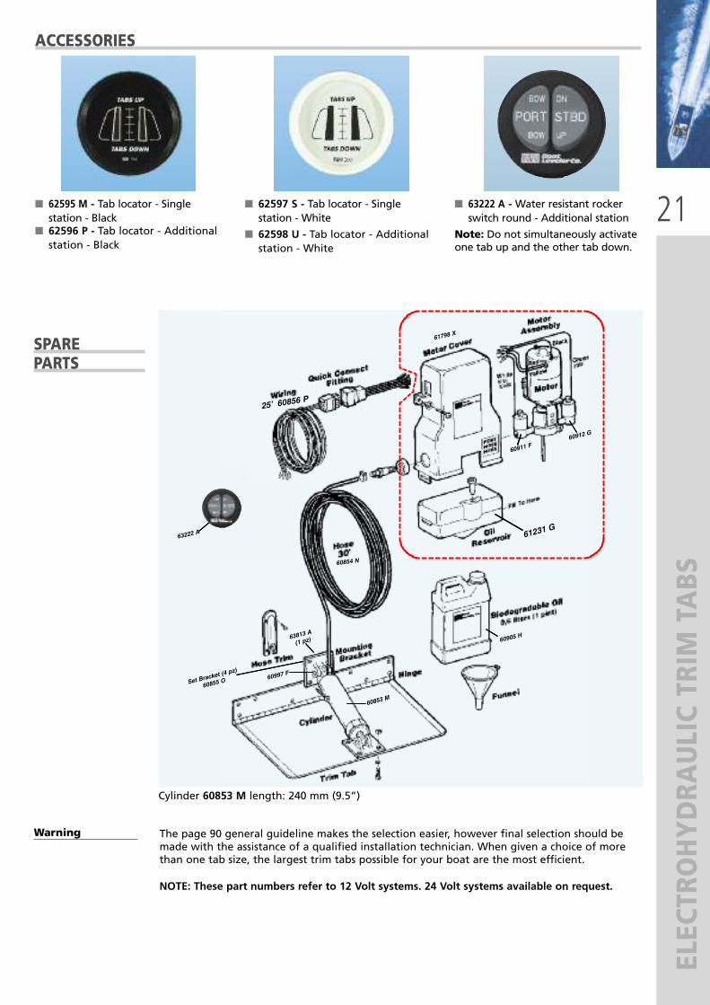
The page 90 general guideline makes the selection easier, however final selection should bemade with the assistance of a qualified installation technician. When given a choice of morethan one tab size, the largest trim tabs possible for your boat are the most efficient.
NOTE: These part numbers refer to 12 Volt systems. 24 Volt systems available on request.
ACCESSORIES
� 62595 M - Tab locator - Singlestation - Black
� 62596 P - Tab locator - Additionalstation - Black
� 63222 A - Water resistant rockerswitch round - Additional station
Note: Do not simultaneously activateone tab up and the other tab down.
� 62597 S - Tab locator - Singlestation - White
� 62598 U - Tab locator - Additionalstation - White
SPARE PARTS
Warning
Cylinder 60853 M length: 240 mm (9.5”)
63222 A
60997 F
60853 M
63813 A
(1 pz)
Set Bracke
t (4 pz)
60855 O
60905 H
61798 X
60912 G
60911 F
25’ 60856 P
60854 N
61231 G

22
ELECTROHYDRA
ULIC TRIM TABS
UNIVERSAL MOTOR PUMPUniversal Motor Pump that fits all brands of hydraulic trim tab motor pumps (eg. Bennettand Trim Master).
BoatLeveler Co.
FEATURES
� Pump has an adjustable pressure relief valve set at 28 Bar.
� Built-in bypass to permit fluid circulation in order to prevent pump stalling.
� Motor has thermal overload protection.
� Kit includes all necessary fittings for a 12V single cylinder system.
� Kit contains biodegradable oil and funnel.
� Heavy duty solenoid valves that lock cylinder in place.
� 45 cm (18”) wire harness with colour coding instructions for other brands.
� Installation instruction included.
� Complete InstaTrim®
system kit in a colourful promotional packaging.
� Especially designed fordistributors.
� When ordering, pleasespecify the optional packaging.
COLOURFUL PACKAGING
Universal Motor Pump - 63736 J

23
MAGNETIC COMPASSES
navigation begins with the right compass
24
MAGNETIC COMPASSES
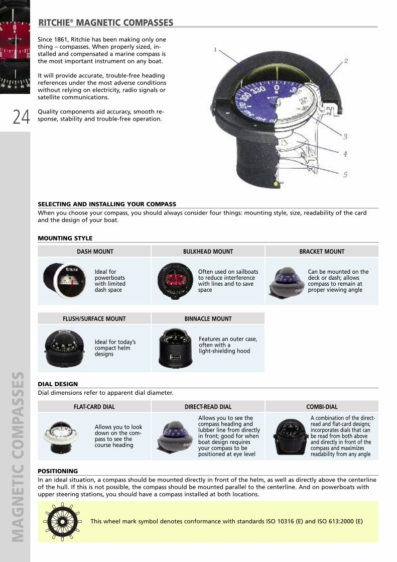
RITCHIE® MAGNETIC COMPASSES
Since 1861, Ritchie has been making only onething – compasses. When properly sized, in-stalled and compensated a marine compass isthe most important instrument on any boat.
It will provide accurate, trouble-free headingreferences under the most adverse conditionswithout relying on electricity, radio signals orsatellite communications.
Quality components aid accuracy, smooth re-sponse, stability and trouble-free operation.
SELECTING AND INSTALLING YOUR COMPASSWhen you choose your compass, you should always consider four things: mounting style, size, readability of the cardand the design of your boat.
POSITIONINGIn an ideal situation, a compass should be mounted directly in front of the helm, as well as directly above the centerlineof the hull. If this is not possible, the compass should be mounted parallel to the centerline. And on powerboats withupper steering stations, you should have a compass installed at both locations.
MOUNTING STYLE
DASH MOUNT BULKHEAD MOUNT BRACKET MOUNT
Ideal for powerboats with limited dash space
Often used on sailboatsto reduce interferencewith lines and to savespace
FLUSH/SURFACE MOUNT BINNACLE MOUNT
Ideal for today’scompact helmdesigns
Features an outer case,often with alight-shielding hood
Can be mounted on thedeck or dash; allows compass to remain at proper viewing angle
DIAL DESIGNDial dimensions refer to apparent dial diameter.
FLAT-CARD DIAL DIRECT-READ DIAL COMBI-DIAL
Allows you to lookdown on the com-pass to see the course heading
Allows you to see thecompass heading andlubber line from directlyin front; good for whenboat design requiresyour compass to bepositioned at eye level
A combination of the direct-read and flat-card designs;incorporates dials that canbe read from both aboveand directly in front of thecompass and maximizes readability from any angle
This wheel mark symbol denotes conformance with standards ISO 10316 (E) and ISO 613:2000 (E)

25
MAGNETIC COMPASSES
X-10-M
X-10-M X-10W-M X-10B-M
X-21BB X-21BU X-21WW
X-21BU
SPORT® SERIESDIAL APP. DIAMETER: 2” (51 mm)
RITCHIE UFLEX DIAL DIAL NIGHTMODEL PART No. APP. Ø MOUNT BOAT TYPE READING LIGHTING COMPENSATORS WEIGHT
X-10-M 67099 B 2” bracket powerboats front 12V green built-in 142 g - 5 oz
X-10W-M 67331 C 2” bracket powerboats front 12V green built-in 142 g - 5 oz
X-10B-M 67332 E 2” bracket powerboats front 12V green built-in 142 g - 5 oz
X-21BB 67333 G 2” bulkhead powerboats front 12V green - 142 g - 5 oz
X-21BU 67334 J 2” bulkhead powerboats front 12V green - 142 g - 5 oz
X-21WW 67335 L 2” bulkhead powerboats front 12V green - 142 g - 5 oz
The dials in magnetic compasses should be balanced to compensate fordip caused by Earth’s magnetic fi eld. All Ritchie® Compasses comestandard for Zone 1 (essentially all of the Northern Hemisphere).When requesting a compass for Zone 2-7, please indicate the zonemost central to your boating area. Once balanced for a specific Zone,the compass will maintain accuracy for one Zone north or south.
CARD BALANCING
X-10 X-20
Mountinghole2 1/16” (56 mm)
REVERSIBLE BRACKET MOUNTThe fully adjustable and reversible Bracketallows a mounting range of over 300° fromoverhead, through angled and vertical
mounts to horizontal surfaces.These mounting position options
and your choice of mounting hardwarepermit mounting on everything from
windshield or supporting frame structures,to slanted dashboards and consoles,
to almost any flat, angledor vertical surface.

26
MAGNETIC COMPASSES
TR-35G TR-31 TR-33W
TR-35 TR-31 TR-33
TR-35W TR-31W TR-33W
TR-35G TR-31G TR-33G
TREK® SERIESDIAL APP. DIAMETER: 2 1/4” (57 mm)
RITCHIE UFLEX DIAL DIAL NIGHTMODEL PART No. APP. Ø MOUNT BOAT TYPE READING LIGHTING COMPENSATORS WEIGHT
TR-35 67346 S 2 1/4” flush powerboats front 12V green built-in 256 g - 9 oz
TR-35W 67347 U 2 1/4” flush powerboats front 12V green built-in 256 g - 9 oz
TR-35G 67348 W 2 1/4” flush powerboats front 12V green built-in 256 g - 9 oz
TR-31 67349 Y 2 1/4” bracket powerboats front 12V green built-in 256 g - 9 oz
TR-31W 67350 G 2 1/4” bracket powerboats front 12V green built-in 256 g - 9 oz
TR-31G 67351 J 2 1/4” bracket powerboats front 12V green built-in 256 g - 9 oz
TR-33 67100 G 2 1/4” surface powerboats front 12V green built-in 256 g - 9 oz
TR-33W 67101 J 2 1/4” surface powerboats front 12V green built-in 256 g - 9 oz
TR-33G 67316 G 2 1/4” surface powerboats front 12V green built-in 256 g - 9 oz
TR-35 TR-31 TR-33
ADJUSTABLE REVERSIBLE BRACKETMOUNT
The fully adjustable and reversible bracketallows a mounting range of over 300° fromoverhead, through angled and vertical
mounts to horizontal surfaces.These mounting position options and yourchoice of mounting hardware permit
mounting on everything from windshield orsupporting frame structures, to slanted
dashboards and consoles, to almost any flat,angled or vertical surface.

27
MAGNETIC COMPASSES
RA-91 RA-93 S-OFF90
ANGLER® SERIES FISHING BOAT COMPASSESDIAL APP. DIAMETER: 2 3/4” (70 mm)
RITCHIE UFLEX DIAL DIAL NIGHTMODEL PART No. APP. Ø MOUNT BOAT TYPE READING LIGHTING COMPENSATORS WEIGHT
RA-91 67352 L 2 3/4” bracket powerboats front 12V green built-in 454 g - 1 lbs
RA-93 67353 N 2 3/4” surface powerboats front 12V green built-in 454 g - 1 lbs
S-OFF90 67354 R 2 3/4” surface powerboats front 12V green built-in 454 g - 1 lbs
RA-91 RA-93 S-OFF90
S-OFF90: 90° off for viewing from starboard
Optional protective cover E-50-C 67355 T: for RA-93 and S-OFF90 magnetic compasses
This wheel mark symbol denotes conformance with standards ISO 10316 (E) and ISO 613:2000 (E)

28
MAGNETIC COMPASSES
F-50 S-53G V-537B
B-51W V-57W.2 D-55
EXPLORER® SERIESDIAL APP. DIAMETER: 2 3/4” (70 mm)
RITCHIE UFLEX DIAL DIAL NIGHTMODEL PART No. APP. Ø MOUNT BOAT TYPE READING LIGHTING COMPENSATORS WEIGHT
F-50 67102 L 2 3/4” flush powerboats front 12V green built-in 454 g - 1 lbs
F-50W 67317 J 2 3/4” flush powerboats front 12V green built-in 454 g - 1 lbs
B-51 67103 N 2 3/4” bracket powerboats front 12V green built-in 454 g - 1 lbs
B-51W 67356 V 2 3/4” bracket powerboats front 12V green built-in 454 g - 1 lbs
B-51G 67318 L 2 3/4” bracket powerboats front 12V green built-in 454 g - 1 lbs
S-53 67104 R 2 3/4” surface powerboats front 12V green built-in 454 g - 1 lbs
S-53W 67320 X 2 3/4” surface powerboats front 12V green built-in 454 g - 1 lbs
S-53G 67319 N 2 3/4” surface powerboats front 12V green built-in 454 g - 1 lbs
V-57.2 67358 Z 2 3/4” dash powerboats front 12V built-in 454 g - 1 lbs
V-57W.2 67359 B 2 3/4” dash powerboats front 12V built-in 454 g - 1 lbs
V-537 67360 K 2 3/4” bulkhead sail front 12V built-in 454 g - 1 lbs
V-537B 67361 M 2 3/4” bulkhead sail front 12V built-in 454 g - 1 lbs
V-537W 67362 P 2 3/4” bulkhead sail front 12V built-in 454 g - 1 lbs
D-55 67357 X 2 3/4” binnacle powerboats front 12V green built-in 454 g - 1 lbs
F-50 B-51 S-53 V-57.2 V-537 D-55
F-50
F-50W
B-51
B-51W
B-51G
S-53
S-53W
S-53G
V-537
V-537B
V-537W
V-57.2
V-57W.2
Optional protective cover E-50-C 67355 T: for F-50, S-53 and D-55 magnetic compassesNote: V-57.2 and V-537 compasses are adjustable to 30°, heel angle to 25°.
Mounting hole 3” (76 mm) Mounting hole 3” (76 mm)

29
MAGNETIC COMPASSES
D-84
F-83 S-87W
F-82W B-81
VOYAGER® SERIESDIAL APP. DIAMETER: 3” (76 mm)
RITCHIE UFLEX DIAL DIAL NIGHTMODEL PART No. APP. Ø MOUNT BOAT TYPE READING LIGHTING COMPENSATORS WEIGHT
D-84 67365 W 3” binnacle powerboats flat-card 12V green built-in 680 g - 1.8 lbs
F-82 67105 T 3” flush powerboats flat-card 12V green built-in 680 g - 1.8 lbs
F-82W 67367 A 3” flush powerboats flat-card 12V green built-in 680 g - 1.8 lbs
F-83 67106 V 3” flush powerboats combi-dial 12V green built-in 567 g - 1.4 lbs
F-83W 67321 Z 3” flush powerboats combi-dial 12V green built-in 567 g - 1.4 lbs
B-80 67363 S 3” bracket powerboats flat-card 12V green built-in 680 g - 1.8 lbs
B-81 67364 U 3” bracket powerboats combi-dial 12V green built-in 680 g - 1.8 lbs
S-87 67322 B 3” surface powerboats combi-dial 12V green built-in 539 g - 1.3 lbs
S-87W 67366 Y 3” surface powerboats combi-dial 12V green built-in 539 g - 1.3 lbs
F-82
F-82W
F-83
F-83W
B-80
B-81
S-87
S-87W
Optional protective cover V-80-C 67368 C: for D-84, F-82 and B-80 compassesOptional protective cover V-83-C 67369 E: for F-83, B-81 and S-87 compasses
D-84 F-82 F-83
B-81
B-80
S-87
Mounting hole 4 1/8” (105 mm) Mounting hole 4 3/16” (107 mm)

30
MAGNETIC COMPASSES
HELMSMAN™ SERIESDIAL APP. DIAMETER: 3 3/4” (94 mm)
RITCHIE UFLEX DIAL DIAL NIGHTMODEL PART No. APP. Ø MOUNT BOAT TYPE READING LIGHTING COMPENSATORS WEIGHT
HF-742 67373 V 3 3/4” flush power/sail flat-card 12V green built-in 907 g - 2 lbs
HF-742W 67323 D 3 3/4” flush power/sail flat-card 12V green built-in 907 g - 2 lbs
HF-743 67107 X 3 3/4” flush power/sail combi-dial 12V green built-in 907 g - 2 lbs
HF-743W 67375 Z 3 3/4” flush power/sail combi-dial 12V green built-in 907 g - 2 lbs
HB-740 67370 N 3 3/4” bracket power/sail flat-card 12V green built-in 907 g - 2 lbs
HB-741 67371 R 3 3/4” bracket power/sail combi-dial 12V green built-in 907 g - 2 lbs
HD-744 67108 Z 3 3/4” binnacle power/sail flat-card 12V green built-in 907 g - 2 lbs
HD-745 67372 T 3 3/4” binnacle power/sail combi-dial 12V green built-in 907 g - 2 lbs
HF-742
HF-742W
HF-743
HF-743W
HB-740
HB-741
HD-744
HD-745
Optional protective cover H-741-C 67376 B: for HF-742, HF-743,HB-740, HB-741,HD-744 and HD-745 compasses
HF-743
HB-741
HF-742
HB-740HD-745
HF-742 HB-741 HD-744
HD-744Mounting hole 4” (102 mm)

31
MAGNETIC COMPASSES
VENTURE® AND SUPERSPORT™ SERIESDIAL APP. DIAMETER: 3 3/4” (94 mm)
RITCHIE UFLEX DIAL DIAL NIGHTMODEL PART No. APP. Ø MOUNT BOAT TYPE READING LIGHTING COMPENSATORS WEIGHT
SR-2 67109 B 3 3/4” bulkhead sail combi-dial - optional 910 g - 2 lbs
high perform. powerdamp +SS-1002 67377 D 3 3/4” flush
power flat-card dial12V green built-in 907 g - 2 lbs
high perform. powerdamp +SS-1002W 67378 F 3 3/4” flush
power flat-card dial12V green built-in 907 g - 2 lbs
SS-PR2 67380 S 3 3/4” bulkhead powerboats combi-dial 12V green built-in 910 g - 2 lbs
SS-1002
SS-1002W SS-PR-2
Venture® compass is provided with protective cover (front and back cover) and with inclinometer INC-45 67381 U. SR-CM2 67382 W compensator is optional.Supersport™ SS-PR2 compass is provided with protective cover.
Optional protective cover H-741-C 67376 B: for SS-1002 compasses
SR-2 SS-1002 SS-PR-2
Mount at any angle upto 45°
SR-CM2Compensator forSR-2 compass (optional)
VENTURE SR-2 SUPERSPORT SS-1002 SUPERSPORT SS-PR2
INC-45
Mounting hole: 4 1/2” (113 mm)
4 5/8” (122 mm) with compensator
Mounting hole 4” (102 mm) Mounting hole 4 5/8” (122 mm)

32
MAGNETIC COMPASSES
NAVIGATOR™ AND SUPERSPORT™ SERIESDIAL APP. DIAMETER: 4 1/2” (114 mm)
RITCHIE UFLEX DIAL DIAL NIGHTMODEL PART No. APP. Ø MOUNT BOAT TYPE READING LIGHTING COMPENSATORS WEIGHT
BN-202 67324 F 4 1/2” bulkhead mount power/sail combi-dial 12V built-in 1050 g - 2.05 lbs
FN-201 67386 E 4 1/2” flush power/sail flat-card 12V green built-in 1190 g - 2.1 lbs
FNW-201 67325 H 4 1/2” flush power/sail flat-card 12V green built-in 1190 g - 2.1 lbs
FN-203 67326 K 4 1/2” flush power/sail combi-dial 12V green built-in 1190 g - 2.1 lbs
FNW-203 67387 G 4 1/2” flush power/sail combi-dial 12V green built-in 1190 g - 2.1 lbs
high perform. powerdamp +SS-2000 67379 H 4 1/2” flushpower flat-card dial
12V green built-in 1190 g - 2.1 lbs
high perform. powerdamp +SS-2000W 67327 M 4 1/2” flushpower flat-card dial
12V green built-in 1190 g - 2.1 lbs
DNB-200 67391 X 4 1/2” binnacle power/sail flat-card 12V green built-in 1650 g - 3.1 lbs
DNW-200 67392 Z 4 1/2” binnacle power/sail flat-card 12V green built-in 1650 g - 3.1 lbs
DNP-200 67393 B 4 1/2” binnacle power/sail flat-card 12V green built-in 1650 g - 3.1 lbs
FN-201
N-LB BOX FNW-201
FN-203
FNW-203
SS-2000
SS-200W
DNB-200
DNW-200
DNP-200WS-P
Weather shield WS-P (optional) – 67403B for DN-200 compasses
Optional protective cover BN-C 67394 D: for BN-202 compassOptional protective cover N-203-C 67395 F: for FN-201, FN-203, SS-2000 and DN-200 compasses
N-LB BOX - 67438 X:Navigator bulkheadleveling block for BN-202 compass
BN-202
FN-201FN-203SS-2000
DNP-200
BN-202 FNW-201 DNP-200
Mounting hole 5 1/8” (130 mm)Mounting hole 5 3/4” (146 mm)

33
MAGNETIC COMPASSESVoltage available on request: 32V
Optional protective cover GM-5-C 67401 X: for SP-5 and D-515-EP compasses
Optional protective cover LL-C 67402 Z: for FB-500 and SS-5000
Weather shield WS-P (optional) 67403 B: for SP-5 and D-515-EP
SP-5B
SP-5C
D-515-EP
D-515-X
SP-5C D-515-EP FB-500
RITCHIE UFLEX DIAL DIAL NIGHTMODEL PART No. APP. Ø MOUNT BOAT TYPE READING LIGHTING COMPENSATORS WEIGHT
SP-5B 67329 S 5” binnacle power/sail flat-card 12V/24V green built-in 2720 g - 6 lbs
SP-5C 67328 P 5” binnacle power/sail flat-card 12V/24V green built-in 2720 g - 6 lbs
D-515-EP 67396 H 5” binnacle power/sail flat-card 12V/24V green built-in 4540 g - 10 lbs
D-515-X 67397 K 5” binnacle power/sail flat-card 12V/24V green built-in 4540 g - 10 lbs
FB-500 67398 M 5” flush power/sail flat-card 12V/24V green built-in 2610 g - 5 lbs
high perform. powerdamp +SS-5000 67399 P 5” flushpower flat-card dial
12V/24V green built-in 2610 g - 5 lbs
high perform. powerdamp +SS-5000W 67400 V 5” flushpower flat-card dial
12V/24V green built-in 2610 g - 5 lbs
SP-5 D-515
SS-5000
FB-500
Mounting hole 6 1/4” (159 mm)
GLOBEMASTER® AND SUPERSPORT™ SERIESDIAL APP. DIAMETER: 5” (127 mm)
FB-500
SS-5000W
SS-5000
All Globemaster® compasses are individually custom assembled to order.
When ordering a Globemaster® compass it is important to specify your choice of power
or sailboat model; 2°, 2° w/points, or 5° dial; 12, 24, or 32-volt night lighting and your choice of
Polished Stainless (P), Black (B) or Polished Brass (X) finish on all models.

34
MAGNETIC COMPASSES
SY-600LL
SY-600PL SY-600PL SY-600PL
SUPER YACHT SERIESDIAL APP. DIAMETER: 5” (127 mm) AND 6” (152 mm)
The Super Yacht Series is a uniqueblend of heritage polished bronze be-zel, dial bushing and modern Ritchiecompass technology.
These materials combine eleganceand workmanship in this high qualitySuper Yacht Series of compasses.
Your compass can be personalizedwith engraving on the bezel.
Each compass is marked with a se-quential coined serial number recor-ded at the factory.
The Super Yacht compass offeringsare an example of Ritchie’s commit-ment to innovation, quality and reliability.
� Binnacle mount� 12V green powerlight lighting (optional 24V or32V)
� 45° or 90° degree lubber lines for easy reading� Built-in compensators� Weight: 907 g – 20 lbFrosted Sunshane Pane – Hood rotate to allowpositioning of sunshade.
2 degreewith nopoints (5” only)
2 degreewith points (5” and 6”)
The SY-500 and SY-600 modelshave either LL
(low level lighting) or PL
(power lighting).
Voltages available: 12, 24 and 32 VDC.
SK-615-C Chrome SK-615-X Polished brass
GLOBEMASTER® SKYLIGHT SERIESDIAL APP. DIAMETER: 6” (152 MM)
SK-615Dimensions
5 degreee(5” and 6”- SuperyachtSeries only)
DIAL STYLES:
new new
35
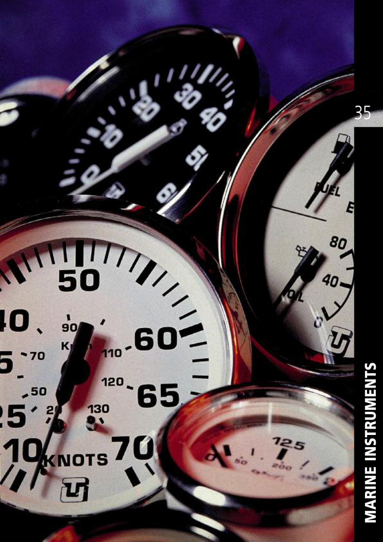
MARINE INSTRU
MEN
TS

36
INSTRU
MEN
TS - ULTRA
AND ULTRA
WHITE SERIES
ULTRA
ULTRA WHITE
FEATURES:� Perimeter-lighted black (ULTRA) or whitedial (ULTRA WHITE) with bold graphics.
� 12V DC, negative ground� Black aluminum bezel.� Flat glass lens.� Metric and american scales.
Uflex instruments are single tested andCE marked according to the EuropeanStandards.

37
INSTRU
MEN
TS - ULTRA
AND ULTRA
WHITE SERIES
ELECTRONIC FLUX-GATE COMPASS
FEATURES:� Auto compensation� Easy to install and to read in all weather conditions� Unaffected by metal objects in the vicinity of the compass indicator� Includes: remote mounted sensor with 20’ plug in harness, instruction manualand mounting hardware
61076 N – ULTRA Style Electronic Compass61077 O – ULTRA WHITE Style Electronic Compass
INSTRUMENT DIAL RANGE DESCRIPTION SENDER ULTRAPART No.
ULTRA WHITEPART No.
Tachometer
Tach-Hourmeter
6000 RPM
7000 RPM
4000 RPM
4000 RPM
7000 RPM
4000 RPM
4000 RPM
• For all 4, 6 & 8 cylinder inboard & I/O gas engine.
• Universal for all outboard engines4, 6, 8, 10, 12 & 20 pole.
• Diesel 5:1, 1:1, 1.5:1, 2:1mechanical take off
• Diesel, variable ratiofor alternator connection
• Universal for all outboard engines4, 6, 8, 10, 12 & 20 pole.• Diesel 5:1, 1:1, 1.5:1, 2:1mechanical take off• Diesel, variable ratio
for alternator connection
Not required
Not required
Page 44
Not required
Not required
Page 44
Not required
60738 G
60509 S
60510 J
60510 J
61766 H
62049 H
62049 H
60691 K
60533 T
60534 U
60534 U
61767 K
62050 S
62050 S
Speedometer30 Knot50 Knot70 Knot
–Requirespitot tube(Page 44)
60512 L60513 M60514 N
60536 W60537 X60538 A
Fuel level gauge E - 1/2 - F – Page 44 - 46 60518 T 60542 U
Water level gauge E - 1/2 - F – Page 46 60520 L 60544 W
Oil pressure gauge 5 bar10 bar – Page 44 60521 M
60522 N60545 X60546 Y
Transmission pressuregauge 25 bar – Not available 60523 O 60547 Z
Water temperaturegauge 40 - 120 °C – Page 44 60526 R 60550 U
Voltmeter 10-16 Volt20-32 Volt
For all 12 Volt electrical systemFor all 24 Volt electrical system
Not requiredNot required
60529 W60741 Z
60553 X60742 A
Hourmeter 10.000hours
Elapsed in hour/tenths, (12-32 volt) Not required 60530 Q 60554 Y
Ammeter 60 - 0 - 60 Indicates electrical charge/dischargerate Not required 60532 S 60540 S
Battery chargeindicator E - 1/2 - F
12 Volt, internally illuminated,remote mounted sensor with 20’
harness includedNot required 62080 B 62081 D
Clock – Quartz analog Not required 60531 R 60539 B
Synchonizer – All twin gas & diesel inboard Not required 60517 Q 60541 T
Rudder angleindicator
Port-Starboard Indicates relative position of rudder Page 44 60699 U 60700 Q
Trim gauge Up-Down
•Mercury & Mariner outboard,Mercruiser, Volvo DP, ’96 & newer,Volvo & Yamaha EST sterndrive.•OMC outboard Johnson & Evinrude. • Yamaha & Evinrude Yamahaoutboard ’97 & newer.
Requires senderfor outboardand sterndrive
engines
61655 Y
62045 Z62047 D
62044 X
62046 B62048 F
HOLE SIZEmm - in
85 - 3.37
85 - 3.37
85 - 3.37
85 - 3.37
85 - 3.37
85 - 3.37
85 - 3.37
85 - 3.3785 - 3.3785 - 3.37
53 - 2.07
53 -2.07
53 - 2.0753 - 2.07
53 - 2.07
53 - 2.07
53 - 2.0753 - 2.07
53 - 2.07
53 - 2.07
53 - 2.07
53 - 2.07
85 - 3.37
53 - 2.07
53 -2.07
53 -2.0753 -2.07
38
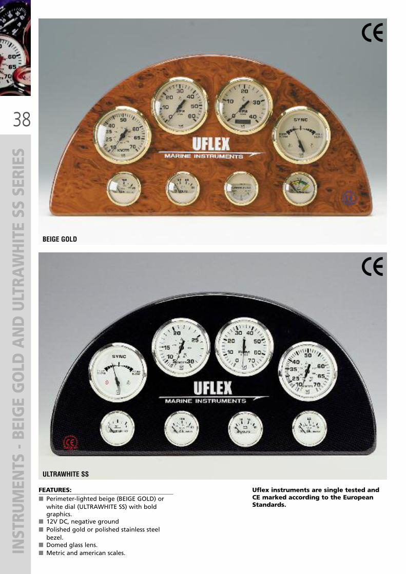
INSTRUMENTS - BEIGE GOLD AND ULTRAWHITE SS SERIES
FEATURES:� Perimeter-lighted beige (BEIGE GOLD) orwhite dial (ULTRAWHITE SS) with boldgraphics.
� 12V DC, negative ground� Polished gold or polished stainless steelbezel.
� Domed glass lens.� Metric and american scales.
BEIGE GOLD
ULTRAWHITE SS
Uflex instruments are single tested andCE marked according to the EuropeanStandards.

39
INSTRUMENTS - BEIGE GOLD AND ULTRAWHITE SS SERIES
ELECTRONIC FLUX-GATE COMPASS
FEATURES:� Auto compensation� Easy to install and to read in all weather conditions� Unaffected by metal objects in the vicinity of the compass indicator� Includes: remote mounted sensor with 20’ plug in harness, instruction manualand mounting hardware
62078 R – BEIGE GOLD Style Electronic Compass62079 T – ULTRAWHITE SS Style Electronic Compass
INSTRUMENT DIAL RANGE DESCRIPTION SENDER BEIGE-GOLDPART No.
U-WHITE SSPART No.
Tachometer
Tach-Hourmeter
6000 RPM
7000 RPM
4000 RPM
4000 RPM
7000 RPM
4000 RPM
4000 RPM
• For all 4, 6 & 8 cylinder inboard & I/O gas engine.
• Universal for all outboard engines4, 6, 8, 10, 12 & 20 pole.
• Diesel 5:1, 1:1, 1.5:1, 2:1mechanical take off
• Diesel, variable ratiofor alternator connection
• Universal for all outboard engines4, 6, 8, 10, 12 & 20 pole.• Diesel 5:1, 1:1, 1.5:1, 2:1mechanical take off• Diesel, variable ratio
for alternator connection
Not required
Not required
Page 44
Not required
Not required
Page 44
Not required
62053 Y
62051 U
62054 A
62054 A
62055 C
62056 E
62056 E
62004 J
62003 G
62005 L
62005 L
62006 N
62007 R
62007 R
Speedometer30 Knot50 Knot70 Knot
–Requirespitot tube(Page 44)
62057 G62058 J62059 L
62008 T62009 V62010 D
Fuel level gauge E - 1/2 - F – Page 44 - 46 62063 B 62014 M
Water level gauge E - 1/2 - F – Page 46 62067 K 62018 W
Oil pressure gauge 5 bar10 bar – Page 44 62065 F
62066 H62016 S62017 U
Transmission pressuregauge 25 bar – Not available 62077 N 62052 W
Water temperaturegauge 40 - 120 °C – Page 44 62073 E 62024 R
Voltmeter 10-16 Volt20-32 Volt
For all 12 Volt electrical systemFor all 24 Volt electrical system
Not requiredNot required
62071 A62072 C
62022 L62023 N
Hourmeter 10.000hours
Elapsed in hour / tenths (12-32 volt) Not required 62064 D 62015 P
Ammeter 60 - 0 - 60 Indicates electrical charge /discharge rate Not required 62060 V 62011 F
Battery chargeindicator E - 1/2 - F
12 Volt, internally illuminated,remote mounted sensor with 20’
harness includedNot required 62061 X 61012 H
Clock – Quartz analog Not required 62062 Z 62013 K
Syncronizer – All twin gas & diesel inboard Not required 62074 G 62025 T
Rudder angleindicator
Port-Starboard Indicates relative position of rudder Page 44 62076 L 62027 X
Trim indicator Up-Down
• For Mercury and Marineroutboards, Mercruiser, Volvo DP,’96 and newer, Volvo and YamahaEST sterndrives• For OMC outboards• For Yamaha outboards ’97 and newer
Requires senderfor outboardand sterndrive
engines
62068 M
62069 P62070 Y
62019 Y
62020 G62021 J
HOLE SIZEmm - in
85 - 3.37
85 - 3.37
85 - 3.37
85 - 3.37
85 - 3.37
85 - 3.37
85 - 3.37
85 - 3.3785 - 3.3785 - 3.37
53 - 2.07
53 - 2.07
53 - 2.0753 - 2.07
53 - 2.07
53 - 2.07
53 - 2.0753 - 2.07
53 - 2.07
53 - 2.07
53 - 2.07
53 - 2.07
85 - 3.37
53 - 2.07
53 -2.07
53 -2.0753 -2.07

40
INSTRUMENTS - DRESS WHITE AND PRO
FESSIONAL SERIES
FEATURES:� Perimeter-lighted white dial with boldblack graphics.
� 12V DC, negative ground� White aluminum bezel.� Flat glass lens.� Metric and american scales.
FEATURES:� Perimeter-lighted black dial with redgraphics.
� 12V DC, negative ground� Black aluminum bezel.� Flat glass lens.� Metric and american scales.
DRESS WHITE
PROFESSIONAL
Uflex instruments are single tested andCE marked according to the EuropeanStandards.

41
INSTRUMENTS - DRESS WHITE AND PRO
FESSIONAL SERIES
ELECTRONIC FLUX-GATE COMPASS
FEATURES:� Auto compensation� Easy to install and to read in all weather conditions� Unaffected by metal objects in the vicinity of the compass indicator� Includes: remote mounted sensor with 20’ plug in harness, instruction manualand mounting hardware
62675 K – DRESS WHITE Style Electronic Compass
INSTRUMENT DIAL RANGE DESCRIPTION SENDER DRESS/WHITEPART No.
Tachometer
Tach-Hourmeter
6000 RPM
7000 RPM
4000 RPM
4000 RPM
7000 RPM
4000 RPM
4000 RPM
• For all 4, 6 & 8 cylinder inboard & I/O gas engine.
• Universal for all outboard engines4, 6, 8, 10, 12 & 20 pole.
• Diesel 5:1, 1:1, 1.5:1, 2:1mechanical take off
• Diesel, variable ratiofor alternator connection
• Universal for all outboard engines4, 6, 8, 10, 12 & 20 pole.• Diesel 5:1, 1:1, 1.5:1, 2:1mechanical take off• Diesel, variable ratio
for alternator connection
Not required
Not required
Page 44
Not required
Not required
Page 44
Not required
62656 F
62657 H
62658 K
62658 K
62659 M
62660 W
62660 W
Speedometer30 Knot50 Knot70 Knot
–Requirespitot tube(Page 44)
62661 Y62662 A62663 C
Fuel level gauge E - 1/2 - F – Page 44 - 46 62664 E
Water level gauge E - 1/2 - F – Page 46 62665 G
Oil pressure gauge 5 bar10 bar – Page 44 62666 J
62667 L
Transmission pressuregauge 25 bar – Not available 62668 N
Water temperaturegauge 40 - 120 °C – Page 44 62669 R
Voltmeter 10-16 Volt20-32 Volt
For all 12 Volt electrical systemFor all 24 Volt electrical system
Not requiredNot required
62670 Z62671 B
Hourmeter 10.000hours
Elapsed in hour / tenths (12-32 volt) Not required 62672 D
Ammeter 60 - 0 - 60 Indicates electrical charge /discharge rate Not required 62673 F
Battery chargeindicator E - 1/2 - F
12 Volt, internally illuminated,remote mounted sensor with 20’
harness includedNot required 62674 H
Clock – Quartz analog Not required 62676 M
Syncronizer – All twin gas & diesel inboard Not required 62677 P
Rudder angleindicator
Port-Starboard Indicates relative position of rudder Page 44 62678 S
Trim indicator Up-Down
• For Mercury and Marineroutboards, Mercruiser, Volvo DP,’96 and newer, Volvo and YamahaEST sterndrives• For OMC outboards• For Yamaha outboards ’97 and newer
Requires senderfor outboardand sterndrive
engines
62679 U
62680 C62681 E
PROFESSIONALPART No.
63196 C
63197 E
63198 G
63198 G
63199 J
63200 P
63200P
63201 S63202 U63203 W
63204 Y
63205 A
63206 C63207 E
63208 G
63209 J
63210 T63211 V
63212 X
63213 Z
63214 B
63216 F
63217 H
63218 K
63219 M
63220 W63219 M
HOLE SIZEmm - in
85 - 3.37
85 - 3.37
85 - 3.37
85 - 3.37
85 - 3.37
85 - 3.37
85 - 3.37
85 - 3.3785 - 3.3785 - 3.37
53 - 2.07
53 - 2.07
53 - 2.0753 - 2.07
53 - 2.07
53 - 2.07
53 - 2.0753 - 2.07
53 - 2.07
53 - 2.07
53 - 2.07
53 - 2.07
85 - 3.37
53 - 2.07
53 -2.07
53 -2.0753 -2.07

42
INSTRU
MEN
TS - PERFORM
ANCE
AND CALYPSO SERIES
FEATURES:� Perimeter-lighted white dial with blackgraphics
� 12V DC negative ground� Stainless steel bezel� Domed glass fog free lens� Metric and American scales
PERFORMANCE
FEATURES:� Perimeter-lighted white dial with boldblack graphics
� Stainless steel bezel� Domed glass fog free lens� 12V DC, negative ground� Metric and American scales
CALYPSO
Uflex instruments are single tested andCE marked according to the EuropeanStandards.

43
INSTRU
MEN
TS - PERFORM
ANCE
AND CALYPSO SERIES
Voltmeter 10-16 Volt20-32 Volt
For all 12 Volt electrical systemFor all 24 Volt electrical system
Not requiredNot required
Hourmeter 10.000hours
Elapsed in hour / tenths (12-32 volt) Not required
Ammeter 60 - 0 - 60 Indicates electrical charge /discharge rate Not required
Clock - Quartz analog Not required
Syncronizer – All twin gas & diesel inboard Not required
Rudder angleindicator
Port-Starboard Indicates relative position of rudder Page 44
Trim indicator Up-Down
• For Mercury and Marineroutboards, Mercruiser, Volvo DP,’96 and newer, Volvo and YamahaEST sterndrives• For OMC outboards
Requires senderfor outboardand sterndrive
engines
65329 F65330 P
65331 S
65332 U
-
65334 Y
65335A
65336 C
65337 E
INSTRUMENT DIAL RANGE DESCRIPTION SENDER HOLE SIZEmm - in
Tachometer
Tach-Hourmeter
6000 RPM
7000 RPM
4000 RPM
4000 RPM
7000 RPM
4000 RPM
4000 RPM
• For all 4, 6 & 8 cylinder inboard & I/O gas engine.
• Universal for all outboard engines4, 6, 8, 10, 12 & 20 pole.
• Diesel 5:1, 1:1, 1.5:1, 2:1mechanical take off
• Diesel, variable ratiofor alternator connection
• Universal for all outboard engines4, 6, 8, 10, 12 & 20 pole.• Diesel 5:1, 1:1, 1.5:1, 2:1mechanical take off• Diesel, variable ratio
for alternator connection
Not required
Not required
Page 44
Not required
Not required
Page 44
Not required
65316 W
65315 U
65317 Y
65317 Y
65318 A
65319 C
65319 C
Speedometer30 Knot50 Knot70 Knot
–Requirespitot tube(Page 44)
65320 L65321 N65322 R
Fuel level gauge E - 1/2 - F – Page 44 - 46 65323 T
Water level gauge E - 1/2 - F – Page 46 65324 V
Oil pressure gauge 5 bar10 bar – Page 44 65325 X
65326 Z
Transmission pressuregauge 25 bar – Not available 65327 B
Water temperaturegauge 40 - 120 °C – Page 44 65328 D
PERFORMANCEPART No.
66649 F66656 C
66650 P
66655 A
66651 S
66641 N
66658 G
66653 W
66652 U
66639 C
66638 A
66640 L
66640 L
-
-
-
66642 R66643 T66644 V
66645 X
66660 T
66646 Z66647 B
66659 J
66648 D
CALYPSOPART No.
85 - 3.37
85 - 3.37
85 - 3.37
85 - 3.37
85 - 3.37
85 - 3.37
85 - 3.37
85 - 3.3785 - 3.3785 - 3.37
53 - 2.07
53 - 2.07
53 - 2.0753 - 2.07
53 - 2.07
53 - 2.07
53 - 2.0753 - 2.07
53 - 2.07
53 - 2.07
53 - 2.07
Battery chargeindicator E - 1/2 - F
12 Volt, internally illuminated,remote mounted sensor with 20’
harness includedNot required 65333 W 66657 E53 - 2.07
85 - 3.37
53 - 2.07
53 - 2.07
53 - 2.07

44
INSTRU
MEN
TS - SEN
DERS AND ACCESSO
RIES
SENDERS AND ACCESSORIES SCALE DESCRIPTION PART No.
Diesel tachometersender - Attaches to diesel sender mechanical take-
off. Includes coupling and 4 drive keys 60613 S
Pitot kits -
Pitot tube complete with transom mountmounting hardware
As above complete with 20’ of tubing
Tubing - 20’
60515 O
60516 P
61717 U
Oil pressure sender
5 bar5 bar10 bar10 bar
Single station, 1/8” NPTFDual station, 1/8” NPTFSingle station, 1/8” NPTFDual station, 1/8” NPTF
60525 Q60610 P60611 Q60612 R
Watertemperaturesender
40 - 120 °C
40 - 120 °C
Single station, 1/8” NPTF
Dual station, 1/8” NPTF
60528 V
60614 T
Fuel level sender 20 - 60 cm(7.9” - 23.6”) Single station 66180 C
Bushing kitTemperatureand pressuresenders
1/8” NPTF - M10x1
1/8” NPTF - M12x1
1/8” NPTF - M16x1.5
60618 Z
60619 A
60620 R
24 Volt adaptorkit 12 - 24V
• Tachometer - Syncronizers• Ammeter - Speedometer (24V bulb only)
• Water temperature• Oil pressure - fuel level - water level - rudder angle
60621 S60623 U60703 T60704 U
Installation kit - Fuel level sender installation kit(for plastic fuel tanks) 60696 P
NOTE: SINGLE SENDER: to connect to one gauge DUAL SENDER: to connect to two gauges
Rudder anglesender -
Single stationDual station
To use with Uflex rudderangle indicator only.
60701 R60702 S
45
INSTRU
MEN
TS- FUEL LEVEL KIT AND PRO
MOTIONAL ITEM
S
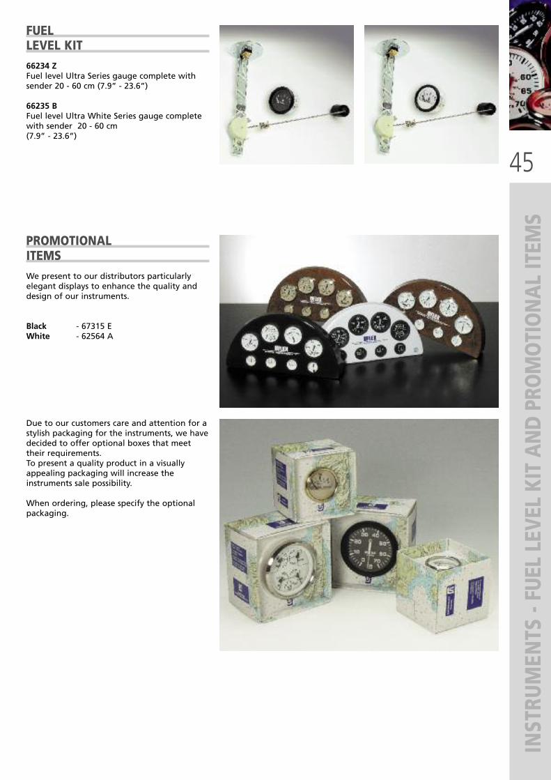
FUELLEVEL KIT66234 ZFuel level Ultra Series gauge complete withsender 20 - 60 cm (7.9” - 23.6”)
66235 BFuel level Ultra White Series gauge completewith sender 20 - 60 cm (7.9” - 23.6”)
PROMOTIONALITEMSWe present to our distributors particularlyelegant displays to enhance the quality anddesign of our instruments.
Black - 67315 EWhite - 62564 A
Due to our customers care and attention for astylish packaging for the instruments, we havedecided to offer optional boxes that meettheir requirements.To present a quality product in a visuallyappealing packaging will increase theinstruments sale possibility.
When ordering, please specify the optionalpackaging.

46
WATER/FUEL AND HOLDING TANK MONITORING SYSTEM
WATER AND FUEL LEVELINDICATORS� Available in black, white colours and withsilver bezel
� 12V/24V DC standard illumination� Resistance rating:- 0 Ohm (empty)- 180 Ohm (full)
� 52 mm (2’’) gauge cut out
FUEL/B - 65836 Z - blackFUEL/B-S - 67869 B - black, silver bezelFUEL/W - 65837 B - whiteFUEL/W-S - 67870 K - white, silver bezelWATER/B - 65838 D - blackWATER/B-S - 67871 M - black, silver bezelWATER/W - 65839 F - whiteWATER/W-S - 67872 P - white, silver bezel
S5 FUEL/WATER SENSORS� Stainless steel� Flange SAE 5-hole - bolt circle 54 mm (2.1”)� Resistance rating:0 Ohm (empty) - 180 Ohm (full)
� S5 sensors interface all Uflex fuel and waterlevel indicators
HOLDING TANK LEVELMONITORING SYSTEMHTG HOLDING TANK LEVEL INDICATORS� Available in black or white colours � 12V/24 Volt DC standard illumination� Resistance rating:240 Ohm (empty) – 33 Ohm (full)
� 52 mm (2’’) gauge cut out
HTG/B - 64683 V - blackHTG/W - 64684 X - white
NOTE: Longer lenghts available on request
S5
MODEL
S5-E150
S5-E175
S5-E200
S5-E225
PART No.
64689 H
64690 S
64691 U
64692 W
S5-E250
S5-E275
S5-E300
S5-E350
64693 Y
64694 A
64695 C
64696 E
S5-E400
S5-E450
S5-E500
S5-E550
64697 G
64698 J
64699 L
64700 S
S5-E600 64701 U
LENGTH
150 mm (5.9”)
175 mm (6.9”)
200 mm (7.9”)
225 mm (8.9”)
250 mm (9.8”)
275 mm (10.8”)
300 mm (11.8”)
350 mm (13.8”)
400 mm (15.7”)
450 mm (17.7”)
500 mm (19.7”)
550 mm (21.7”)
600 mm (23.6”)
FUEL/B
S3H HOLDING TANK SENSORS� Stainless steel� HFL - 64719 P Flange 1 1/4” - NPT threads(to be ordered separately)
� Resistance rating:240 Ohm (empty) – 30 Ohm (full)
LENGTH MODEL
100 mm (3.9”) S3H-1
205 mm (8.0”) S3H-2
305 mm (12.0) S3H-3
410 mm (16.1”) S3H-4
PART No.
64685 Z
64686 B
64687 D
64688 F
FUEL/B-S FUEL/W FUEL/W-S
WATER/B WATER/B-S WATER/W WATER/W-S
HTG/B HTG/W
WATER AND FUEL LEVEL MONITORING SYSTEM
HFL 64719 P S3H

47
GPS / TACH
OMETER / HO
URMETER / TEMPERATURE IN
DICATORS
GPS SPEEDO� Speed (0-60 knots) shown analogically andcompass heading digitally, both guided byGPS signals.
� GPS Speedo has a “high-end” 32 channelGPS Receiver suitable for all types of boats(12V)
� Easy to install, it has a favourable price.� GPS Speedo is in no way dependant of theboat main control and monitoring systems.
� Hole diameter: 85 mm (3.37”)
IGPS-BB-60 - 66878 X - black dial and bezel,12VDC, speed 0-60 knotsIGPS-WW-60 - 66879 Z - white dial and bezel,12VDC, speed 0-60 knots
TACHOMETERWITH HOURMETER� Available in black or white colours withsilver bezel
� 12/24 Volt DC standard illumination� Scale: 4000 RPM or 8000 RPM � 85 mm (3,3”) gauge cut out
IMHB-BS-4KL - 67873 S - black / 4000 RPMIMHB-WS-4KL - 67874 U - white / 4000 RPMIMHB-BS-8KL - 67875 W - black / 8000 RPMIMHB-WS-8KL - 67876 Y - white / 8000 RPM
HOURMETER� Available in black or white colours withsilver bezel
� 12/24 Volt DC standard illumination� LCD Display� Scale: 10.000 hours � 52 mm (2”) gauge cut out
ICUR-BS - 67877 A - black with silver bezelICUR-WS - 67878 C - white with silver bezel
WATER TEMPERATURELEVEL INDICATORS� Available in black or white colours withsilver bezel
� 12/24 Volt DC standard illumination� Resistance rating: 450-23 Ohm � Scale: 25 – 120°C � 52 mm (2”) gauge cut out
IPTR-BS - 67879 E - black with silver bezelIPTR-WS - 67880 N - white with silver bezel
OIL TEMPERAURELEVEL INDICATORS� Available in black or white colours withsilver bezel
� 12/24 Volt DC standard illumination� Resistance rating: 450-23 Ohm� Scale: 25 – 120°C� 52 mm (2”) gauge cut out
IPYR-BS - 67881 R - black with silver bezelIPYR-WS - 67882 T - white with silver bezel
IGPS-WW-60IGPS-BB-60
IMHB-WS-4KLIMHB-BS-4KL
IMHB-WS-8KLIMHB-BS-8KL
ICUR-WSICUR-BS
IPTR-WSIPTR-BS
IPYR-WSIPYR-BS
new new
new new
new new
new new

48
PRESSURE AND
RUD
DER AN
GLE INDICATORS / CLOC
KS
OIL PRESSURELEVEL INDICATORS� Available in black or white colours withsilver bezel
� 12/24 Volt DC standard illumination� Resistance rating: 10-180 Ohm � Scale: 0 – 2 Bar, 0 – 5 Bar, 0 – 10 Bar o 0 – 25 Bar
� 85 mm (3,3”) gauge cut out
IORP-BS-02 - 67883 V - black (0-2 Bar)IORP-WS-02 - 67884 X - white (0-2 Bar)IORP-BS-05 - 67885 Z - black (0-5 Bar)IORP-WS-05 - 67886 B - white (0-5 Bar)IORP-BS-010 - 67887 D - black (0-10 Bar)IORP-WS-010 - 67888 F - white (0-10 Bar)IORP-BS-025 - 67889 M - black (0-25 Bar)IORP-WS-025 - 67890 S - white (0-25 Bar)
RUDDER ANGLE INDICATORS� Available in black or white colours withsilver bezel
� 12/24 Volt DC standard illumination� Resistance rating: 0-190 Ohm� Scale: 25 – 120°C� 52 mm (2”) gauge cut out
IMRR-BS - 67891 U - black with silver bezelIMRR-WS - 67892 W - white with silver bezel
CLOCKS� Available in black or white colours withsilver bezel
� 12/24 Volt DC standard illumination� Not standby battery� 52 mm (2”) gauge cut out
IMCR-BS - 67893 Y - black with silver bezelIMCR-WS - 67894 A - white with silver bezel
IORP-WS-02IORP-BS-02
IORP-WS-05IORP-BS-05
IORP-WS-010IORP-BS-010
IORP-WS-025IORP-BS-025
IMRR-WSIMRR-BS
IMCR-WSIMCR-BS
new new

49
TRIM INDICATORS / VOLTMETERS / A
MMETERS
TRIM INDICATORS � Available in black or white colours withsilver bezel
� 12/24 Volt DC standard illumination� Resistance rating:- 10 Ohm - 180 Ohm
� 52 mm (2”) gauge cut out
TRIM-BS-10-180 - 67895 C - black with silverbezelTRIM-WS-10-180 - 67896 E - white with silverbezel
VOLTMETERS� Available in black or white colours withsilver bezel
� 12V, 24V o 12/24V DC standard illumination� Scale: 8-16V, 18-32V or 8-32V� 52 mm (2”) gauge cut out
IPVR-BS-8-16 - 67899 L - black 8-16VIPVR-WS-8-16 - 67900 S - white 8-16VIPVR-BS-18-32 - 67901 U - black 18-32VIPVR-WS-18-32 - 67902 W - white 18-32VIEVR-BS-8-32 - 67903 Y - black 8-32VIEVR-WS-8-32 - 67904 A - white 8-32V
AMMETERS� Available in black or white colours withsilver bezel
� 12/24 Volt DC standard illumination� Scale: 8-32V� 52 mm (2”) gauge cut out� Supplied with sensor
AMP KIT-BS - 67905 C - black with silver bezelAMP KIT-WS - 67906 E - white with silver bezel
TRIM-WS-10-180TRIM-BS-10-180
IPVR-WS-8-16IPVR-BS-8-16
IPVR-WS-18-32IPVR-BS-18-32
IEVR-WS-8-32IEVR-BS-8-32
IMCR-WSAMP KIT-BS
new new

50
DIGITAL INSTRU
MEN
TS
FUEL MANAGERFOR GASOLINE ENGINES
The Fuel Manager System consists of a digital fuelgauge and fuel flow transducer that monitorsand measures fuel as it is being used.The gauge shows not only how much fuel hasbeen used but, more importantly, how much isleft.Other features include a settable “low fuelalarm”, trip log and total fuel consumed log.Fuel flow is measured in litres (2,5 to 160 litresper hour) or gallons (0.5 to 34 gallons per hour).� 53 mm ( 2.07”) gauge cut out
FUEL MANAGER - 62778 WFuel Manager includes 1 gauge and 1 fuelflow sender.
Fuel Manager is for use on gasolineengines only.
SPARE SENDERS FOR DIGITAL INSTRUMENTS
DIGITAL INSTRUMENTS Digital instruments featuring the most advanced technology in the electronic field. They are supplied complete withsenders. Available in Dress White style only: white dial and bezel.
NOTE: Senders aresupplied with
the instrument.
MODEL SUPPLIED WITH:PART No.
Fuel flow sender Fuel Manager64310 C
Depth sender Depth Sounder64311 E
FUEL MANAGER
DEPTH SOUNDER� 61 meter Depth Sounder with Keel Offset,Automatic Gain and Shallow/Deep alarms.Depth Sounder measures in Meters, Feet orFathoms.
� Out-of-range indication.� Shallow and deep alarms are both audiableand visible to operator.
� Quick-Set mode for rapid adjustment orsettings.
� Back illumination for maximum nigh vision.� Keel-Offset adjustment and indication.� 53 mm ( 2.07”) gauge cut out
DEPTH SOUNDER - 62777 UDepth Sounder includes 1 gauge. 1 depth senderand 1 installation cable.
DEPTH SOUNDER

51
FRESH WATER AND BILGE PUMPS
52
FRESH WATER PUMPS
Aqua KingTM Junior 2.0 Aqua KingTM Standard 3.0 Aqua KingTM Premium 4.0
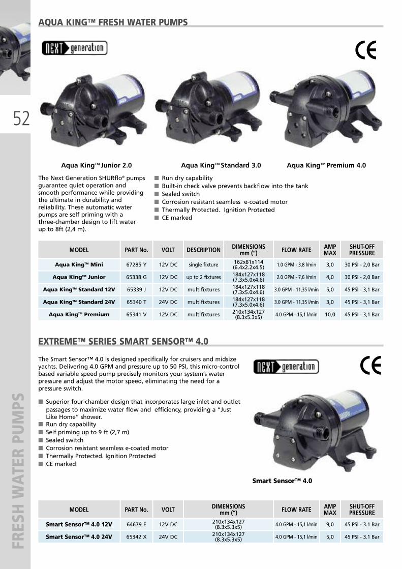
AQUA KING™ FRESH WATER PUMPS
EXTREME™ SERIES SMART SENSOR™ 4.0
� Run dry capability� Built-in check valve prevents backflow into the tank � Sealed switch � Corrosion resistant seamless e-coated motor� Thermally Protected. Ignition Protected� CE marked
The Next Generation SHURflo® pumpsguarantee quiet operation andsmooth performance while providingthe ultimate in durability andreliability. These automatic waterpumps are self priming with a three-chamber design to lift water up to 8ft (2,4 m).
The Smart Sensor™ 4.0 is designed specifically for cruisers and midsizeyachts. Delivering 4.0 GPM and pressure up to 50 PSI, this micro-controlbased variable speed pump precisely monitors your system’s waterpressure and adjust the motor speed, eliminating the need for apressure switch.
� Superior four-chamber design that incorporates large inlet and outletpassages to maximize water flow and efficiency, providing a “JustLike Home” shower.
� Run dry capability� Self priming up to 9 ft (2,7 m)� Sealed switch � Corrosion resistant seamless e-coated motor� Thermally Protected. Ignition Protected� CE marked
Smart Sensor™ 4.0
64679 E 210x134x127(8.3x5.3x5)
65342 X 210x134x127(8.3x5.3x5)
12V DC
24V DC
4.0 GPM - 15,1 l/min
4.0 GPM - 15,1 l/min
Smart Sensor™ 4.0 12V
Smart Sensor™ 4.0 24V
9,0
5,0
45 PSI - 3.1 Bar
45 PSI - 3.1 Bar
65338 G 184x127x118(7.3x5.0x4.6)
65339 J 184x127x118(7.3x5.0x4.6)
65340 T 184x127x118(7.3x5.0x4.6)
65341 V
12V DC
12V DC
24V DC
12V DC 210x134x127(8.3x5.3x5)
2.0 GPM - 7,6 l/min
3.0 GPM - 11,35 l/min
3.0 GPM - 11,35 l/min
4.0 GPM - 15,1 l/min
Aqua KingTM Junior
Aqua KingTM Standard 12V
Aqua KingTM Standard 24V
Aqua KingTM Premium
up to 2 fixtures
multifixtures
multifixtures
multifixtures
4,0
5,0
3,0
10,0
30 PSI - 2,0 Bar
67285 Y 162x81x114(6.4x2.2x4.5)12V DC 1.0 GPM - 3,8 l/minAqua KingTM Mini single fixture 3,0 30 PSI - 2,0 Bar
45 PSI - 3,1 Bar
45 PSI - 3,1 Bar
45 PSI - 3,1 Bar
PART No. DIMENSIONSmm (“)VOLT FLOW RATE MODEL DESCRIPTION AMP
MAXSHUT-OFFPRESSURE
PART No. DIMENSIONSmm (“)VOLT FLOW RATE MODEL AMP
MAXSHUT-OFFPRESSURE

53
FRESH WATER PUMPS
HighFlow
Strainer
EXTREME™ SERIES HIGH FLOW STRAINER
SHURflo® highly recommends the use of the Extreme™ Series High FlowStrainer, engineered to compliment the higher performance of theSmart Sensor™, to keep your Extreme™ Series Pumps flowing strong byprotecting it from debris in the water. Easy installation and even easierto clean.
Extreme™ Series High Flow Strainer - 63735 GMounting Bracket – 65368 S – Brushed stainless steel (optional)
EXTREME™ SERIES SMART SENSOR™ 5.7
The Smart Sensor™ 5.7 is a micro processor control based variable speedpump that delivers over 5 GPM (21,6 l/min) and pressure up to 60 PSI (4,1Bar). SHURflo® Smart Sensor™ 5.7 precisely monitors your system’s waterpressure and adjust the motor speed, thus eliminating the need for apressure switch.
� Superior five-chamber design that incorporates large inlet andoutlet passages to maximize water flow and efficiency, providinga “Just Like Home” shower
� O-ring sealed end bells along with the protected electronicpackage make the Smart Sensor™ capable of handling even theharshest marine enviroments
� Current limiting and over/under voltage protection� Pressure sensor eliminates cycling and the need for anaccumulator tank
� Run dry capability� Self priming up to 9 ft (2,7 m)� Sealed switch � Corrosion resistant seamless e-coated motor� Quick-Connect fittings included� Thermally Protected. Ignition Protected� CE marked
Smart Sensor™ 5.7
12,7 cm
13,6 cm
10,1cm
10,1 cm
23,4 cm
12,3cm
Smart Sensor 5.7
12,1 cm
10,2 cm12,7 cm
20,5 cm
7,6 cm 9,1 cm
13,4 cm
9,9cm
Smart Sensor 4.0
63194 Y 235x127x121(9.3x5.0x5.5)
64335 V 235x127x121(9.3x5.0x5.5)
12V DC
24V DC
5.0 GPM - 18,9 l/min
5.0 GPM - 18,9 l/min
Smart Sensor™ 5.7 12V
Smart Sensor™ 5.7 24V
12
5
60 PSI - 4,1 Bar
60 PSI - 4,1 Bar
PART No. DIMENSIONSmm (“)VOLT FLOW RATE MODEL AMP
MAXSHUT-OFFPRESSURE

54
WASHDOWN PUMPS
WASHDOWN PUMPS
Perfect for tough washdown applications, such as fishbox, scaling and anchor chain cleaning, these ruggedself-priming pumps deliver high lift, can run drywithout damage, and won’t overheat with extendeduse.
� Run dry capability� Sealed switch � Corrosion resistant seamless e-coated motor� Thermally Protected. Ignition Protected� CE marked
Blaster™ ProBlaster Junior™
65862 A 203x127x118 (7.6x5.0x4.6)
65863 C 203x127x118 (7.6x5.0x4.6)
12V DC
24V DC
3.5 GPM - 13,2 l/min
3.5 GPM - 13,2 l/min
Blaster™ 12V
Blaster™ 24V
6
4,5
45 PSI - 3,1 Bar
66560 N 203x127x118 (7.6x5.0x4.6)12V DC 2.0 GPM - 7,6 l/minProblaster Junior™ 12V 4 30 PSI - 2 Bar
45 PSI - 3,1 Bar
EXTREME™ PROBLASTER™ WASHDOWN PUMPSThe Extreme™ ProBlaster™ delivers over 5 GPM (20 l/min) and pressure upto 45 PSI (3,1 Bar), giving you the ultimate in washdown capabilities. Thishigh volume pump will clean your deck quickly and easily. The corrosionresistant coated seamless motor shell with sealed switch provides excellentprotection against the harsh marine anvironment. The Extreme™ ProBlaster™ is designed for the toughest washdown applications.
� Superior five-chamber design that incorporates large inlet and outletpassages to maximize water flow and efficiency
� Current limiting and over/under voltage protection� Run dry capability� Self Priming � Sealed switch � Corrosion resistant seamless e-coated motor with o-ring sealed endbells
� Quick-Connect fittings included� Thermally Protected. Ignition Protected� CE marked Problaster™ Extreme™ Series
64337 Z 235x127x140 (9.3x5.0x5.5)
64338 B 235x127x140 (9.3x5.0x5.5)
12V DC
24V DC
5.3 GPM - 20,1 l/min
5.3 GPM - 20,1 l/min
Extreme™ Problaster™ 12V
Extreme™ Problaster™ 24V
12
6
45 PSI - 3,1 Bar
45 PSI - 3,1 Bar
PART No. DIMENSIONSmm (“)VOLT FLOW RATE MODEL AMP
MAXSHUT-OFFPRESSURE
PART No. DIMENSIONSmm (“)VOLT FLOW RATE MODEL AMP
MAXSHUT-OFFPRESSURE

55
LIVEW
ELL AND UTILITY PUMPS
DIMENSIONImm (“)
406x318 (16.0x12.5)
CODICE
64681 R
PORTATA
1.5 GPM - 5,6 l/min
MODEL
Sistema Cambio Olio
AMPMAX
4,5
RACCORDI
3/8” F NPT
SHURflo’s new washdown kit includeseverything you need for toughwashdown applications all in one box.The kit includes the Next GenerationProBlaster™ Pump, Fittings, Blaster™Nozzle, Raw Water Strainer and a 7,6 m(25’) coiled hose.� CE marked
WASHDOWN KIT
Pro Washdown kit
MACERATOR PUMPS
Designed specifically for sanitation waste and fish box evacuations,SHURflo’s Macerator pump features a premium impeller design.
� Run dry capability� Self Priming � SHURflo’s unique dual blade and housing construction ensuresproblem free pumping
� Thermally Protected. Ignition Protected� CE marked
Macerator
65303 L 210x136x127 (8.3x5.3x5.0)12V DC 4.0 GPM - 15,1 l/minPro Washdown Kit 10 45 PSI - 3,1 Bar
274x97x114(10.8x3.8x4.5)62767 R 12V DC 13 GPM - 50 l/minMacerator 12V 14 inlet: 1.5” barb / 1,5 NPT
outlet: 1” barb
274x97x114(10.8x3.8x4.5)62768 T 24V DC 13 GPM - 50 l/minMacerator 24V 8 inlet: 1.5” barb / 1,5 NPT
outlet: 1” barb
406x318 (16.0x12.5)64681 R 1.5 GPM - 5,6 l/minOil Change System 4,5 3/8” F NPT
64681 R
OIL CHANGE, WINTERIZINGAND LIQUID TRANSFER SYSTEMIncorporating SHURflo’s advanced motor technology that includesthermal overload protection, these pumps are self-priming, easy toinstall and are extremely versatile.
� 13 litres (3,5 gal) storage container – 2,4 m (8’) cable with batteryclips and hose kit included
� Reversible switch � Motor : 12V DC permanent magnet, continuous duty� Self Priming up to 1,82 m (6’)� Thermal overload protection� CE marked
PART No. DIMENSIONSmm (“)VOLT FLOW RATE MODEL AMP
MAXSHUT-OFFPRESSURE
DIMENSIONSmm (“)PART No. VOLT FLOW RATE MODEL AMP
MAX PORT SIZE
DIMENSIONSmm (“)PART No. FLOW RATE MODEL AMP
MAX PORT SIZE

56
SHURFLO PUMPS - ACCESSO
RIES
PRE-PRESSURIZED ACCUMULATOR TANK
Reduces cycling pulsation and pressure spikes, increases the life of yourpump and even saves battery power. SHURflo® accumulator tank is NSFcertified.
� Easy handles pressure requirements from 1,4 Bar (20 PSI) to 8,8 Bar(125 PSI)
� 1/2” male threaded Ports - Uses standard SHURflo® fittings� Can be mounted in-line� Nylon housing/Butyl Bladder� CE marked
Nylon Tank
24 oz - 0,7 litres Nylon Tank 125 PSI - 8,8 Bar232x121x97(9.1x4.8x3.8) 20 PSI - 1,4 Bar 65861 Y
PRESSURE REGULATED CITY WATER ENTRIESAn exclusive diaphragm design prevents high-pressure damage oftencaused by city water systems. Leak-tight, stress and crack-resistant,these high-performance water entries limitwater pressure safely to 50 or 65 PSI (3.5 or 4.5 Bar) while meeting orsurpassing all check valve code requirements
63378 J - Wall mount Pressure regulator - Chrome64717 K- Wall mount Pressure regulator - White65306 T - Hose Adapter fitting 1/2” NPT (F) x 3/4” GSH (M)
63378 J
64717 K65306 T
TOTALVOLUMEMODEL MAXIMUM
PSI - BARDIMENSIONS
mm (“) PRECHARGEDPART No.
The pump may be mounted upto 6’ (1.8 m) vertical above thesource. Wiring should beswitched above the source.Wiring should be switched aswell as fused with therecommended size fuse. Inletside of all fresh water pumpsshould include the use of aSHURflo® strainer. Mount the pump in anaccessible area for a strainerinspection. Refer to installationinstruction included forindividual pump recommendedwire and fuse size.
FRESH WATER MULTI-FIXTURE SYSTEMS
Potable WaterTank Pump
Faucet Shower
Strainer
WaterHeater

57
SHURFLO PUMPS - ACCESSO
RIES AND SPARE PARTS
SPARE PARTS
STRAINERS
FITTINGS
FITTINGSMODEL DESCRIPTIONPART No.
1/2” (13 mm)barb inlet
Swivel nut strainer
Protects pumps from harmfuldebris. High capacity, rugged nylon housing,
slide out easy to clean screen.
66526 N
1/2” (13 mm)barb inlet
In-line checkvalve
Allows flow in one directiononly to safeguard agains back-surge up to 6,8 Bar (1000 PSI)
61125 F
3/4” (19 mm)female
High PressureBlaster Nozzle
High impact plastic for long life.Use with SHURflo® pumps
or garden hose. Adjust to fine mist or full stream.Lock clip for continuous spray.
61120 A
1/2” (13 mm)female
In-Line Strainer
Protects pumps from harmfuldebris. High capacity, rugged nylon housing,
slide out easy to clean screen.
63185 X
63185 X
61125 F
66526 N
61120 A
MODEL
Straight fitting 1/2” NPT (f) x 3/8”
PART No.
61129 L
Elbow fitting 1/2” NPT (f) x 3/8” 61130 C
Straight fitting 1/2” NPT (f) x 1/2” 61127 H
Elbow fitting 1/2” NPT (f) x 1/2” barb swivel 61128 K
Straight fitting 1/2” NPT (f) x 3/4” barb swivel 64220 B
Elbow fitting 1/2” NPT (f) x 3/4” barb swivel 64340 M
Straight adaptor 1/2” NPT (m) x 1/2” 61132 E
1 Complete headpump 2 Headpump and switch kit 3 Valve kit4 Diaphragm kit
61128 K 61129 L
DESCRIPTION
Valve Kit for Blaster, Junior, Standard, Premium pumps
PART No.
61214 F
Diaphragm kit for Junior pump 61217 I
Diaphragm kit for Standard, pumps 61216 H
Pump head Junior, Standard, Premium, Blaster 63181 N
Diaphragm kit for Premium, Blaster pumps 63180 L
Pump head and switch kit for Standard 12V, 30PSI 62526 S
Pump head and switch kit for Standard,Premium, Blaster 12V/24V, 45PSI
63182 R
Complete head pump for Junior 12V, 20PSI 61721 J
Complete head pump for Standard, 12V/24V, 45 PSI 63183 T
Complete head pump for Junior 12V, 20PSI 61768 M
Pump head and switch kit for Junior 12V, 20 PSI 61413 K
Complete head pump for Premium, Blaster 12V/24V, 45 PSI 63184 V
Impeller for Macerator pump 63432 M

58
BILGE PUMPS
SHURFLO® BILGE PUMPS380/500/700/1000 GPH
Quality bilge pumps you can trust. SHURflo® bilge pumpsare built for the harsh marineenviroment to withstand the toughest conditions.Water cooled motors for extended life.
� Continuous duty� Submersible with 6’ (1,8 m) tinned wire assembly� Tough nylon housing� Quick-snap swivel baseplate� Ignition pretected. ISO 8849
Shurflo® 380/500/700/1000 GPH
66528 T 114x95 (4.5x3.75)
66529 V 114x95 (4.5x3.75)
66530 D 114x95 (4.5x3.75)
12V DC
12V DC
12V DC
500 GPH - 32 l/min
700 GPH - 42 l/min
1000 GPH - 63 l/min
Bilge 500
Bilge 700
Bilge 1000
1,8
3,2
3,2
3/4” - 19 mm
66527 R 114x95 (4.5x3.75)
60 (2 3/8)
60 (2 3/8)
60 (2 3/8)
60 (2 3/8)12V DC 380 GPH - 24 l/minBilge 380 1,7 3/4” - 19 mm
3/4” - 19 mm
3/4” - 19 mm
1500/2000 GPH
Heavy duty and built to last. SHURflo®’s 1500 and2000 GPH nylon bilge pumps offer a unique motorcooling system (patent pending) to ensure efficientperformance and long life. Installation is a snap withour patented swivel base.
� Continuous duty� Submersible with 6’ (1,8 m) tinned wire assembly� Anti-air lock� Run dry without damage� Quick-snap swivel baseplate� Commercial duty� Ignition pretected. ISO 8849
66531 F 183x152 (7.2x6)
66532 H 183x152 (7.2x6)
12V DC
24V DC
1500 GPH - 94,6 l/min
1500 GPH - 94,6 l/min
Bilge 1500/12
Bilge 1500/24
8
-
1 1/8” - 28,5 mm
1 1/8” - 28,5 mm
66533 K 183x152 (7.2x6)
66534 M 183x152 (7.2x6)
12V DC
24V DC
2000 GPH - 126 l/min
2000 GPH - 126 l/min
Bilge 2000/12
Bilge 2000/24
10
-
1 1/8” - 28,5 mm
1 1/8” - 28,5 mm
Shurflo® 1500/2000 GPH
PART No. DIMENSIONSmm (“)VOLT FLOW RATE MODEL AMP
MAX OUTLETØ BASEmm (“)
PART No. DIMENSIONSmm (“)VOLT FLOW RATE MODEL AMP
MAX BARB OUTLET

59
BILGE PUMPS - IN
-LINE BLOWERS
VOLT
12/24V DC
MODEL
SWS
DESCRIPTION
Standard float switch
PART No.
66535 P
DIMENSIONSmm (“)
116x53x40(4.6x2.1x1.6)
12/24V DCSWSC Protected cage switch66536 S116x53x40(4.6x2.1x1.6)
12V DCSW12V Wema® switch65840 P147xØ37(5.7xØ1.4)
FLOAT SWITCHES
The SHURflo® float switches provide theultimate in reliability for your boat.
Complete line includes a solid state control,standard float switch and protected cageswitch.
Manufactured in corrosion resistant andexplosion proof material. They can be used forany kind of pump and also for water bilge andother alarm systems.
Wema® SwitchThe switch turns the pump on and offautomatically and is typically placed in thebilge.
SWSC
SWS
SW12V
SHURFLO® YELLOW TAIL™3” AND 4” IN-LINEBILGE BLOWERSShurflo® in-line blowers provide ventilationfor engine compartments, galleys, bilge andheads. Mounting feet allow vertical orhorizontal installation in confined spaces.
� Wider base-plate and oval screw hole forease of installation
� Splash-proof motor with rubber boot� Heavy duty shaft seal� High volume air flow - low current draw� Longer barb for ease of duct connection� CE, ISO 9097 and Ignition Protected
IN-LINE BILGE BLOWERS
12V DC
12V DC
76 mm - 3”
100 mm - 4”
130x140x96 (5.1x5.5x3.8)
130x162x122 (5.1x6.4x4.8)
3,8
5,5
3,3 m3/min
6,0 m3/min
64703 Y
64704 A
VOLT HOSE INT. Ø DIMENSIONSmm (“) DRAW AMP AIR FLOW PART No.

60
RECESSED
AND TRA
NSO
M SHOWERS
RECESSED SHOWERS
Practical, versatile and fashionable showers.Simply pull out the sprayer and extend it toany area of your boat for the ultimate inwashdown versatility.
65311 K - Recessed shower white ABS plasticcup with trigger sprayer, stainless steelinstallation hardware and 1.8 m (6’) heavyduty white hose. Deck or wall mount.
65312 M - Recessed cup white ABS plastic cupwith stainless steel installation hardware
65311 K
TRANSOM SHOWER
65313 P
65312 M
Functional, practical and durable showers.Combine the convenience and simplicity of therecessed shower, with the added benefit of ashut-off valve to create an all-in-one packagefor your exterior shower needs.
65313 P - Two handle hot/cold transom shower.White ABS plastic box with trigger sprayer,stainless steel installation hardware and 1.8 m(6’) heavy duty white hose. Vertical or horizontal mount.

61
OIL CHANGE SYSTEM
S

62
OIL CHANGE SYSTEM
S
OP-6 IMPELLER PUMP The Reverso® OP-6 is a useful transfer pumpsuitable for oil, diesel or water. The OP-6 cantransfer hot or cold oil quickly and cleanly toand from the engine oil pan. The threeposition switch has a safety lock that preventsaccidental activation.The switch is directionally oriented (flow is indirection of switch) for easy operation. MeetsISO 8846 standards.
OP-700 MANIFOLD OIL CHANGE SYSTEMSThe OP-700 oil change systems feature a fullyreversible OP-6 pump and are available on 2,3, 4, 5, 6 valve options. They are mounted ona base to obtain a permanent installation:connecting these assemblies on equipmentsthat need regular oil change they simplify theoperation and reduce time and chances of oilspills.
OP-SERIES FEATURES� Reversible (they draw and fill engines)� Powerful DC high torque motor � Self priming� Nickel plated brass pump body� Impeller: Nitrile (oil) – Fluoroelastomer (diesel fuel)
� Built in switch, switch guard and fuse � Easily changed impeller � CE certified
OIL CHANGE IMPELLER PUMPSOP-SERIES
OP-6
OP-704
OP-706
OP-700 Dimensions
TECHINICAL SPECIFICATIONS OP-6 OP-700
Pump port: est. M 3/4”- int. F 3/8” NPT 1/2” flare
Manifold ports: - 1/2” F NPT
Flow rate: 11,4 l/min (3.0 GPM) 7,8 l/min (2.0 GPM)
Self priming: 0,9 m (3 ft) 0,9 m (3 ft)
Lift: 3,0 m (10 ft) 3,0 m (10 ft)
Working pressure: from 0 to 1 bar (15 PSI) from 0 to 1 bar (15 PSI)
Motor: 12V DC or 24V DC 12V DC or 24V DC
Amp: 12 Amp (12V) – 6 Amp (24V) 12 Amp (12V) – 6 Amp (24V)
Dimensions W x H: 24,4 x 9,1 cm (9.6” x 3.6”)
Weight: 2,7 kg (6 lbs)
MODEL No. VALVES WEIGHTkg (lbs)
DIMENSIONSA cm (“) B cm (“)
OP-702 2 valve 24,4 (9.6) 22,4 cm (8.8) 4,5 (10)
OP-703 3 valve 26,9 (10.6) 22,4 cm (8.8) 5,0 (11)
OP-704 4 valve 29,5 (11.6) 22,4 cm (8.8) 5,5 (12)
OP-705 5 valve 36,2 (14.3) 22,4 cm (8.8) 5,9 (13)
OP-706 6 valve 41,2 (16.3) 22,4 cm (8.8) 6,8 (15)

63
OIL CHANGE SYSTEM
S
OIL CHANGE OR TRANSFER DIESEL FUEL GEAR PUMPS GP-SERIES
GP-301
GP-301 AC
GP-602, GP-602 AC PUMPSGear pumps able to move lowviscosity fluids, NOT designedfor heavy oil. The durable GP-602 pump combines a small sizewith a high flow capacity.
GP-602 AC
TECHNICAL SPECIFICATIONS GP-201 GP-301 GP-302 GP-301 AC
Ports: M 3/8’’ NPT M 3/8’’ NPT M 3/8’’ NPT M 3/8’’ NPT
Max work press: 1,7 bar (25 PSI) 1,7 bar (25 PSI) 2,8 bar (40 PSI)
Flow rate: 5,6-11,4 l/min (1.5-3 GPM) 9.5-13,3 l/min (2.5-3.5 GPM) 9.5-13,3 l/min (2.5-3.5 GPM) 13.6 l/min (3.6 GPM)
Self priming (wet gears): 0.5 m (1.5 ft) 1.5 m (5 ft) 1.5 m (5 ft) 1.5 m (5 ft)
Lift: 1,5 m (5 ft) 3 m (10 ft) 9,1 m (30 ft) 30,4 m (100 ft water)
Pump body: brass brass brass brass
Gears: bronze bronze bronze bronze
Motor: 12V or 24V DC 12V or 24V DC 12V or 24V DC AC self ventilated
Fuse/Breaker: 10 Amp (12V)-5 Amp (24V) 10,5 Amp (12V)-6,8 Amp (24V) 15 Amp (12V)-7,5 Amp (24V) 5 Amp (220V)
Dimensions W x H cm (“): 12,8x7,4 (5x2.9) 13,7x7,6 (5.4x3) 14,7x9,6 (5.8x3.8) 26,4x16,3 (10.4x6.4)
Weight: 0,9 kg (2 lbs) 2,7 kg (6 lbs) 3,2 kg (7 lbs) 4,5 kg (10 lbs)
GP-201, GP-301, GP-302, GP-301 AC PUMPS Compact, powerful, self-priming DC gearpumps. The bronze gears and stainless steelshaft enable the pumps to move a variety ofviscous and non-viscous fluids. They aredurable and fit easily in the tightest spaces.They are available in both 12 and 24 Volt DC.
TECHNICAL SPECIFICATIONS GP-602 GP-602 AC
Ports: M 1/2” NPT M 1/2” NPT
Flow rate: 22,7 l/min (6 GPM) 32,2 l/min (8,5 GPM)
Self priming (wet gears): 1,5 m (5 ft) 6 m (20 ft)
Lift: 18,2 m (60 ft water) 36,5 m (120 ft water)
Pump body: brass brass
Gears: bronze bronze
Motor: 12V or 24V DC AC self ventilated
Fuse/Breaker: 15 Amp (12V) - 10 Amp (24V) 5 Amp (220V)
Dimensions W x H cm (“): 17,8x10,1(7x4) 32x19,3 (12.6x7.6)
Weight: 3,6 kg (8 lbs) 6,4 kg (14 lbs)
GP-602
GP-302
GP-201

64
OIL CHANGE SYSTEM
S
GP-3010, GP-3020 , GP-700 MANIFOLD OILCHANGE SYSTEMSThe gear pump manifold oil change systemsservice multiple engines, transmissions andgenerators. Compact, reversible (they drawand fill engines) and self-priming, theysimplify oil changes and reduce chances of oilspills. Valve options from 3 to 7.
APPLICATIONS
� Single engines up to 450 hp : OP-6, GP-301� Multiple engines up to 450 hp : GP-3010� Single engines from 300 to 800 hp : GP-302� Multiple engines from 300 to 800 hp : GP-3020, GP-700� Multiple engines from 600 to 2000 hp : GP-700
MULTI-VALVE MANIFOLDSThese manifolds allow multiple hoses to be connected to one pump. The assemblies can be mounted in any direction.Mounting holes are pre-drilled for easy installation.
TECHNICAL SPECIFICATIONS
� Manifold ports: 1/2” F NPT� Valves: Nickel chromed full flow ball valve� Max working press: 9 bar (150 PSI) � Mounting holes: 3/16”
OIL CHANGE OR TRANSFER DIESEL FUEL GEAR PUMPS GP-SERIES
GP-3025
GP-705
PART. No. MULTI-VALVE MANIFOLD
61477A VA-2 2 valve assembly
61572U VA-3 3 valve assembly
64741G VA-4 4 valve assembly
62976A VA-5 5 valve assembly
TECHNICAL SPECIFICATIONS GP-3010 GP-3020 GP-700
Pump port: 1/2” flare 1/2” flare 1/2” flare
Manifold ports: 1/2” F NPT 1/2” F NPT 1/2” F NPT
Flow rate: 9,5 l/min (2.5 GPM) 11,4 l/min (3 GPM) 11,4 l/min (3 GPM)
Self priming (wet gears): 1,5 m (5 ft) 1,5 m (5 ft) 1,5 m (5 ft)
Lift: 3 m (10 ft ) 7,6 m (25 ft ) 9,1 m (30 ft )
Motor: 12V or 24V DC 12V or 24V DC 12V or 24V DC
Fuse/Breaker: 8,8 A (12V) - 5,3 A (24V) 9,8 A (12V) - 4 A (24V) 15 A (12V) - 7,5A (24V)
GP-3010 Dimensions GP-700 Dimensions
No. VALVES MODEL A X B cm (“) MODEL A X B cm (“) MODEL A X B cm (“)
2 valve GP-3012 26x22 (10.2x8.6) - -
3 valve GP-3013 26x22 (10.2x8.6) GP-3023 29x11,5 (11.5x4.5) GP-703 37x12 (14.5x4.7)
4 valve GP-3014 30x22 (11.8x8.6) GP-3024 36x11,5 (14.2x4.5) GP-704 37x12 (14.5x4.7)
5 valve GP-3015 37x22 (14.5x8.6) GP-3025 36x11,5 (14.2x4.5) GP-705 37x12 (14.5x4.7)
6 valve GP-3016 42x22 (16.5x8.6) - GP-706 42x12 (16.5x4.7)
7 valve - - GP-707 42x12 (16.5x4.7)
DIMENSIONS A x B cm (“)

65
OIL CHANGE SYSTEM
S
OP-700 PORTABLE OIL CHANGERThe OP-700 oil change system, featuring a full reversibile pump,connects directly to the dipstick tube. Portable or permanent, thissystem includes a poly-mounting board with handy carry handle,stainless steel cover plate, a safety switch lock and 6’ of marine gradewire. Ideal for gas applications, the heavy duty motor pumps hot orcold oil.
GP-301P PORTABLE OIL CHANGERThis system is designed to remove the oil from 4 cycle outboardengines quickly and with no mess.Simply hang the unit on the engine cawling, insert the nylon hoseinto the dipstick tube and attach the wire to a 12V power source. Oil isdrained into a container and can be removed from the boat for properdisposal.
FEATURES
� Powerful reversible pumps specially designed to be used with oils.� Self priming� Compact size� Exceptional high flow rate� Built-in switch and circuit breaker � OP-700 impeller: Nitrile (oil) – Fluoroelastomer (diesel fuel)� GP-301P: brass pump body, bronze gears and stainless steel shaft� CE certified
PORTABLE PUMP SYSTEMS
OP-700
GP-301 P
PART No. MODEL DESCRIPTION
61636 U 360010 Oil transfer impeller (Nitrile)
61637 W 360014 Diesel fuel transfer impeller
61638 Y 360120 OP-6 Seal
61639 A SRK-360 Kit 1 impeller and seal - oil
61640 J 97360-2 Kit 2 impellers and seals - oil
61641 L SRK-370 Kit 1 impeller and seal – diesel fuel /oil
61642 N 97370-2 Kit 2 impellers and seals - diesel fuel /oil
61643 R 36003 3 way switch (on-off-on)
TECHNICAL SPECIFICATIONS OP-700 GP-301P
Ports: est. M 3/4”- int. F 3/8” NPT 3/8” M JIC
Flow rate: 11,4 l/min (3.0 GPM) 11,4 l/min (3.0 GPM)
Self priming: 0,9 m (3 ft) 1,5 m (5 ft)
Lift: 3,0 m (10 ft) 4,5 m (15 ft)
Working press: from 0 to 1 bar (15PSI) -
Motor: 12V DC or 24V DC 12V DC or 24V DC
Amp: 7Amp (12V) – 3 Amp (24V) 8,8 Amp (12V) – 5,3 Amp (24V)
Weight: 3,6 kg (8 lbs) 2,7 kg (6 lbs)
SPARE PARTS

66
FUEL PRIMING AND POLISHING SYSTEM
S
FP-301 FUEL PRIMING SYSTEMThe Reverso® Fuel Primer pumps fuel into the fuel lines, purgingtrapped air in the main feeding line and from primary filters,secondary filters and engines. To protect delicate fuel systems, allprimers have integral pressure relief valves which are factory set todeliver the proper fuel pressure for each engine.
TECHNICAL SPECIFICATIONS � Ports: 1” NPT � Valve : 1” NPT full flow� Amp: 10A (12V) – 5A (24V)� Size: 25x29x11 cm (10”x11.4”x4.4”)
FUEL PRIMING AND POLISHING SYSTEMS
FP-301
FPS FUEL POLISHING SYSTEMSFPS Systems have been designed for fuel polishing directly in the tanksremoving 99% of water and particulates.They eliminate the build-up of algae and water in the tanks reducingthe costs of filter maintenance.FPS Systems include control panel and service filter alarm.
FPS-150
TECHNICAL SPECIFICATIONS FPS-80 FPS-150 FPS-210 AC
Inlet and Outlet ports: 1/2” # 8 JIC M 1/2” # 8 JIC M 1/2” # 8 JIC M
Flow rate: 300 l/h (80 GPH) 570 l/h (150 GPH) 795 l/h (210 GPH)
Self priming (system primed): - 1.5 m (5 ft) 1.5 m (5 ft)
Max lift: 1,2 m vertical (4 ft) 3.0 m (10 ft ) 9,1 m (30 ft )
Motor: 12V or 24V DC 12V or 24V DC AC perm. magnets
Amp: 3 A (12V) – 1,5 A (24V) 10 A (12V) – 5 A (24V) 1,4 (220V)
Dimensions W x H cm (“): 47x39 (18.5x15.5) 47x39 (18.5x15.5) 59x50 (23.2x20)
Weight: 9,5 kg (21 lbs) 11,3 kg (25 lbs) 27,2 kg (60 lbs)
All REVERSO products have a 5 year warranty and are CE certified.

67
MARINE PUMPS AND BLOWERS
A world of marine equipment
®®

68
ELECTRIC PUMPS
35ϒ35ϒ
B
A
C
MODEL Ø IN mm (“) Ø OUT mm (“) A mm (“) B mm (“) C mm (“) WEIGHT kg (lbs)
U020 20 (0.8) 20 (0.8) 260 (10.2) 195 (7.7) 145 (5.7) 5.5 (12.1)
U025 25 (1) 25 (1) 305 (12) 213 (8.4) 178 (7) 9.2 (20.3)
U030 30 (1.2) 30 (1.2) 330 (13) 232 (9.1) 215 (8.5) 13 (28.6)
U040 40 (1.6) 40 (1.6) 352 (13.8) 232 (9.1) 230 (9) 18 (39.7)
U050 50 (1.9) 50 (1.9) 435 (17.1) 247 (9.7) 245 (9.6) 26.5 (58.4)
U070 70 (2.7) 70 (2.7) 705 (27.7) 280 (11) 360 (14.2) 75 (165.3)
MODEL VOLT MAX MAX MAX MAXAMP INLET HEAD DELIVERY
12V DC 26 AU020
24V DC 14 A4 m (13.1’) 10 m (32.8’) 28 l/min
12V DC 38 AU025
24V DC 22 A6 m (19.7’) 12 m (39.4’) 52 l/min
12V DC 44 AU030
24V DC 28 A6 m (19.7’) 18 m (59.0’) 75 l/min
U040 24 V DC 45 A 6 m (19.7’) 22 m (72.2’) 120 l/min
U050-MT 230V AC/380V AC - 6 m (19.7’) 30 m (98.4’) 250 l/min
U070-T 380V AC - 6 m (19.7’) 40 m (131.2’) 500 l/min
BRONZE SELF-PRIMING - ELECTRIC PUMPS
U070U050
U040U030
U020
Self-priming side liquid ring electric pumps used to empty bilges and transfer uninflammable liquids such as: freshwater, sea water, fuel diesel and generallyall low viscosity and free of solid impurities liquids.
Standard featuresBronze pump body, bronze impeller, AISI 316 stainless steel shaft, corrosion-proofclamping rings, continuous duty electric motorwith F insulation class, IP55 protection.BSP threads on pumps.Delivery diagram: page 81.
Application limits Uninflammable liquids free of solid impurities.Liquid temperature range: from 0° C to 70° C.Static pressure internal to the pump body: 6bar max.
DIMENSIONS AND WEIGHTS

69
ELECTRIC PUMPS
A
B
CDIMENSIONS AND WEIGHTS
MODEL Ø IN Ø OUT A mm (“) B mm (“) C mm (“) WEIGHT kg (lbs)
USBM-midex 1” 1/4 BSP-F 1” 1/4 BSP-F 373 (14.7) 160 (6.3) 180 (7.1) 16 (32.3)
MODEL VOLT MAX MAX MAX MAXAMP INLET HEAD DELIVERY
USBM - midex 24V DC 28 A 6 m (19.7’) 27 m (88.6’) 64 l/min
USBM-midex
USBM-midex SELF-PRIMING ELECTRIC PUMP
Rotary self-priming bi-directional volumetricelectric pump used on boats to empty wastetanks, toilet sewage and particularly viscousoily fluids or liquids with small debries insuspension.
Standard featuresAISI 316 stainless steel body pump, neopreneimpeller, AISI 316 stainless steel shaft,corrosion-proof clamping rings, continuousduty electric motor with F insulation class,IP44 protection.Delivery diagram: page 81
Application limits Never let the USBM-Midex pump run whenempty. Liquid temperature range: from 0° C to 70° C.Static pressure internal to the pump body: 6bar max.For use as oil and/or fuel transfer pump it isnecessary nitrile impeller (available onrequest).
Spare impellers:� Neoprene impeller - 66538 W� Nitrile impeller(for only transfer) - 66539 Y

70
ELECTRIC PUMPS
UCE 03
CENTRIFUGAL ELECTRIC PUMPS - UCE SERIES
Single impeller centrifugal electric pumps usedto transfer and/or supply large quantity ofliquid. They are used to transferuninflammable liquids such as diesel fuel or todeliver fresh water to those equipments thatrequire a high water flow rate (eg. airconditioning units).
Standard featuresAluminum pump body, noryl impeller, AISI 420stainless steel shaft, cast iron support , woundfield electric motor. F insulation class. IP 20protection.Delivery diagram: page 81
Application limitsSolid impurities free liquid, liquid temperaturerange from 0 to + 50 C°, max static internalpressure of the pump body: 6 bar.
MODEL VOLT MAX MAX MAX MAXAMP INLET HEAD DELIVERY
UCE 03-12 12V DC 38 A 4 m (13.1’) 20 m (65.6’) 65 l/min
UCE 03-24 24V DC 28 A 4 m (13.1’) 28 m (91.8’) 70 l/min
DIMENSIONS AND WEIGHTS
MODEL Ø IN Ø OUT A mm (“) B mm (“) C mm (“) WEIGHT kg (lbs)
UCE 03-12/24 1” 1” 260 (10.2) 125 (4.9) 140 (5.5) 6 (13.2)
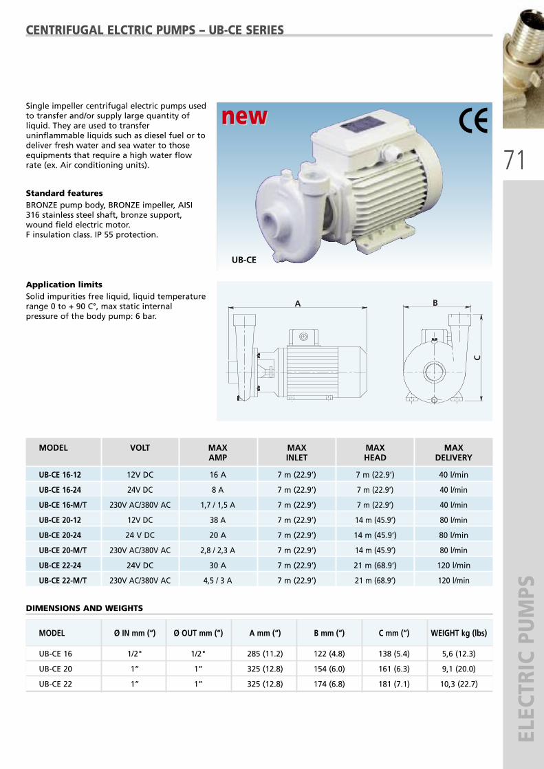
MODEL Ø IN mm (“) Ø OUT mm (“) A mm (“) B mm (“) C mm (“) WEIGHT kg (lbs)
UB-CE 16 1/2" 1/2" 285 (11.2) 122 (4.8) 138 (5.4) 5,6 (12.3)
UB-CE 20 1” 1” 325 (12.8) 154 (6.0) 161 (6.3) 9,1 (20.0)
UB-CE 22 1” 1” 325 (12.8) 174 (6.8) 181 (7.1) 10,3 (22.7)
71
ELECTRIC PUMPS
CENTRIFUGAL ELCTRIC PUMPS – UB-CE SERIES
Single impeller centrifugal electric pumps usedto transfer and/or supply large quantity ofliquid. They are used to transferuninflammable liquids such as diesel fuel or todeliver fresh water and sea water to thoseequipments that require a high water flowrate (ex. Air conditioning units).
Standard featuresBRONZE pump body, BRONZE impeller, AISI316 stainless steel shaft, bronze support,wound field electric motor.F insulation class. IP 55 protection.
Application limitsSolid impurities free liquid, liquid temperaturerange 0 to + 90 C°, max static internalpressure of the body pump: 6 bar.
UB-CE
DIMENSIONS AND WEIGHTS
A B
C
MODEL VOLT MAX MAX MAX MAXAMP INLET HEAD DELIVERY
UB-CE 16-12 12V DC 16 A 7 m (22.9’) 7 m (22.9’) 40 l/min
UB-CE 16-24 24V DC 8 A 7 m (22.9’) 7 m (22.9’) 40 l/min
UB-CE 16-M/T 230V AC/380V AC 1,7 / 1,5 A 7 m (22.9’) 7 m (22.9’) 40 l/min
UB-CE 20-12 12V DC 38 A 7 m (22.9’) 14 m (45.9’) 80 l/min
UB-CE 20-24 24 V DC 20 A 7 m (22.9’) 14 m (45.9’) 80 l/min
UB-CE 20-M/T 230V AC/380V AC 2,8 / 2,3 A 7 m (22.9’) 14 m (45.9’) 80 l/min
UB-CE 22-24 24V DC 30 A 7 m (22.9’) 21 m (68.9’) 120 l/min
UB-CE 22-M/T 230V AC/380V AC 4,5 / 3 A 7 m (22.9’) 21 m (68.9’) 120 l/min
new new

72
ELECTRIC PUMPS
MODEL Ø IN mm (“) Ø OUT mm (“) A mm (“) B mm (“) C mm (“) WEIGHT kg (lbs)
UABR 32/1 100 (3.9) 140 (5.5) 690 (27.2) 135 (5.3) 247 (9.7) 56 (123.4)
UABR 32/2 100 (3.9) 140 (5.5) 730 (28.7) 135 (5.3) 247 (9.7) 60 (132.3)
UABR 40/1 110 (4.3) 150 (5.9) 785 (30.9) 155 (6.1) 272 (10.7) 70 (154.3)
UABR 32/1-M/T 100 (3.9) 140 (5.5) 680 (26.7) 135 (5.3) 247 (9.7) 40 (88.2)
UABR 32/2-M/T 100 (3.9) 140 (5.5) 720 (28.3) 135 (5.3) 247 (9.7) 44 (97.0)
UABR 40/1-M/T 110 (4.3) 150 (5.9) 780 (30.7) 155 (6.1) 272 (10.7) 58 (127.8)
UABR 40/2-M/T 110 (4.3) 150 (5.9) 840 (33.1) 155 (6.1) 272 (10.7) 75 (165.3)
UABR 50/2-M/T 125 (4.9) 165 (6.5) 1100 (43.3) 170 (6.7) 325 (12.8) 132 (291.0)
UABR 65/2-M/T 145 (5.7) 185 (7.3) 1225 (48.2) 195 (7.6) 360 (14.2) 202 (445.3)
BRONZE SELF-PRIMING ELECTRIC PUMPS - UABR SERIES
Multi-stage bronze self-priming electric pumpfitted with radial impellers. These pumps arewidely used to empty bilges, to attend fireequipments, to wash chains, to transfer fueldiesel etc.
Standard featuresBronze pump body, bronze impellers, AISI 316stainless steel shaft, continuous duty electricmotor with F insulation class, IP20 protection.
Application limits Solid impurities free liquid, liquid temperaturerange from 0 to + 90 C°, max static internalpressure of the pump body: 20 bar.
DIMENSIONS AND WEIGHTS
MODEL VOLT MAX MAX MAX MAXAMP INLET HEAD DELIVERY
UABR 32/1 24V DC 52 A 9 m (29.5’) 28 m (91.8’) 160 l/min
UABR 32/2 24V DC 90 A 9 m (29.5’) 52 m (170.6’) 160 l/min
UABR 40/1 24V DC 90 A 9 m (29.5’) 40 m (131.2’) 250 l/min
UABR 32/1-M/T 230V AC/380V AC 9,6/4,8 A 9 m (29.5’) 28 m (91.8’) 150 l/min
UABR 32/2-M/T 230V AC/380V AC - 9 m (29.5’) 50 m (164’) 150 l/min
UABR 40/1-M/T 230V AC/380V AC 14/9 A 9 m (29.5’) 38 m (124.7’) 220 l/min
UABR 40/2-M/T 230V AC/380V AC - 9 m (29.5’) 75 m (246’) 220 l/min
UABR 50/2-M/T 230V AC/380V AC - 9 m (29.5’) 82 m (269’) 400 l/min
UABR 65/2-M/T 230V AC/380V AC - 9 m (29.5’) 85 m (278.8’) 600 l/min
UABR

73
ELECTRIC PUMPSMODEL Ø IN mm (“) Ø OUT mm (“) A mm (“) B mm (“) C mm (“) WEIGHT kg (lbs)
USBR-12/24 1” 1” 500 (19.7) 160 (6.3) 190 (7.5) 15 (33)
USBR-M/T 1” 1” 465 (18.3) 160 (6.3) 210 (8.3) 16,5 (36.4)
BRONZE/STAINLESS STEEL SELF-PRIMING ELECTRIC PUMPS – USBR SERIES
Bronze self-priming electric pumps fitted witha worm screw rotor. These pumps are widelyused to empty waste tanks, toilet sewage andparticularly viscous fluids or liquids with smalldebries in suspension.
Standard featuresBRONZE pump body, AISI 316 stainless steelrotor, AISI 316 stainless steel shaft, permanentmagnet electric motor with F insulation class.IP 44/55 protection.
Application limitsLiquid temperature range from 0 to +70°C,max static internal pressure of the pumpbody: 6 bar.
DIMENSIONS AND WEIGHTS
A
B
CMODEL VOLT MAX MAX MAX MAX
AMP INLET HEAD DELIVERY
USBR-12 12V DC 36 A 6 m (19.7’) 50 m (164) 50 l/min
USBR-24 24V DC 20 A 6 m (19.7’) 50 m (164) 50 l/min
USBR-M/T 230V AC/380V AC 4 / 3,6 A 6 m (19.7’) 50 m (164) 50 l/min
USBR
new new

74
ELECTRIC PUMPS AND WATER PRESSURE SYSTEM
S
UJ-INOX
SELF-PRIMING STAINLESS STEEL ELECTRIC PUMPSAND WATER PRESSURE SYSTEMS – UJ SERIES
UJ SERIES ELECTRIC PUMPSSelf-priming centrifugal electric pumps, Jet type, with high suctioncapacity. These electric pumps are used to deliver pressurized water toon-board appliances (showers, toilets, washbasins etc.).
Standard featuresAISI 304 stainless steel pump body, noryl diffuser and venture tube,AISI 316 stainless steel shaft, corrosion-proof clamping rings,continuous duty electric motor with F insulation class.Delivery diagram: page 81.
Application limits Liquid free of solid impurities, liquid temperature range: from 0° C to50° C, static pressure inside the pump body: 6 bar max.
UJ-INOX 20X
WATER PRESSURE SYSTEMS - UJ SERIES UJ-INOX water pressure systems are equipped with UJ electricpumps and with a stainless steel cylindrical tank (X) with inside butylrubber diaphragm suitable for food stuff, widely used for constantwater pressure for all on-board appliances such as kitchens, showers,washbasins etc.
Standard featuresManual safety pressure switch, pressure gauge, non return valve, 5 ways brass pipe fitting.
MODEL SWITCH TANK MAX MAX TANKPRE-SET PRESSURE DELIVERY PRESSURE CAPACITY
UJ-INOX 12/8X 1.4-2.0 bar 1.2 bar 50 l/min 3.0 bar 8 l
UJ-INOX 12/20X 1.4-2.0 bar 1.2 bar 50 l/min 3.0 bar 20 l
UJ-INOX 24/8X 1.4-2.8 bar 1.2 bar 50 l/min 3.8 bar 8 l
UJ-INOX 24/20X 1.4-2.8 bar 1.2 bar 50 l/min 3.8 bar 20 l
UJ-INOX M/20X 1.4-3.5 bar 1.2 bar 50 l/min 4.8 bar 20 l
DIMENSIONS AND WEIGHTS
MODEL Ø IN Ø OUT A B C WEIGHTmm (“) mm (“) mm (“) kg (lbs)
UJ-INOX 12/24-8X 1” BSP-F 1” BSP-F 400 (15.7) 225 (8.8) 430 (16.9) 13 (28.6)
UJ-INOX 12/24-20X 1” BSP-F 1” BSP-F 400 (15.7) 260 (10.2) 575 (22.6) 15 (33.0)
UJ-INOX M-20X 1” BSP-F 1” BSP-F 400 (15.7) 260 (10.2) 575 (22.6) 13.5 (29.7)
MODEL VOLT MAX MAX MAX MAXAMP INLET HEAD DELIVERY
UJ-INOX 12 12V DC 40 A 9 m (29.5’) 30 m (118.8’) 50 l/min
UJ-INOX 24 24V DC 28 A 9 m (29.5’) 38 m (124.7’) 50 l/min
UJ-INOX M 220V AC 3 A 9 m (29.5’) 48 m (188.9’) 50 l/min

75
ELECTRIC PUMPS AND WATER PRESSURE SYSTEM
SUMG-INOX 20X
UMG SERIES - WATER PRESSURE SYSTEMSUMG-INOX water pressure systems are equipped with a UMGseries electric pump and with a stainless steel cylindrical tank (X) withinside butyl rubber diaphragm suitable for food stuff, widely used forconstant water pressure for all on-board appliances such as kitchens,showers, washbasins etc.
Standard featuresManual safety pressure switch, pressure gauge, non return valve, 5 ways brass pipe fitting.
UMG-INOX
SELF-PRIMING BRONZE ELECTRIC PUMPSAND WATER PRESSURE SYSTEMS - UMG SERIES
UMG SERIES ELECTRIC PUMPSSelf-priming electric pumps featuring 4 impellers that allow for ahigher pressure and flow rate then the UJ-Inox pumps.
Standard featuresAISI 304 stainless steel pump body, noryl diffuser and Venturi tube, AISI316 stainless steel shaft, corrosion-proof clamping rings, continuousduty electric motor with F insulation class. Delivery diagram: page 81.
Application limits Liquid free of solid impurities. Liquid temperature range: from 0° C to50° C.Static pressure inside the pump body: 6 bar max.
MODEL VOLT MAX MAX MAX MAXAMP INLET HEAD DELIVERY
UMG-INOX 24 24V DC 28 A 9 m (29.5’) 50 m (164.0’) 90 l/min
UMG-INOX M 220V AC 3 A 9 m (29.5’) 50 m (164.0’) 90 l/min
MODEL SWITCH TANK MAX MAX TANKPRE-SET PRESSURE DELIVERY PRESSURE CAPACITY
UMG-INOX 24/20X 1.4 – 3.5 bar 1.2 bar 90 l/min 5 bar 20 l
UMG-INOX M/20X 1.4 – 3.5 bar 1.2 bar 90 l/min 5 bar 20 l
DIMENSIONS AND WEIGHTS
MODEL Ø IN Ø OUT A B C WEIGHTmm (“) mm (“) mm (“) kg (lbs)
UMG-INOX 24-20X 1” BSP-F 1” BSP-F 570 (22.4) 260 (10.2) 575 (22.6) 20 (44.0)
UMG-INOX M-20X 1” BSP-F 1” BSP-F 570 (22.4) 260 (10.2) 575 (22.6) 16.5 (36.4)

76
ELECTRIC PUMPS AND WATER PRESSURE SYSTEM
S
UJBR
SELF-PRIMING BRONZE ELECTRIC PUMPSAND WATER PRESSURE SYSTEMS - UJBR SERIES
UJBR SERIES ELECTRIC PUMPSSelf-priming electric pumps, Jet type, with closed impeller, featuring a highsuction capacity. These electric pumps are used for rising both fresh and seawater and to deliver pressurized water to on-board appliances(showers, toilets, washbasins etc), to air-conditioning units, anti-fireequipment. Used for washing of decks and chains.
Standard featuresBronze pump body, polycarbonate diffuser and Venturi tube, AISI 316 stainlesssteel shaft, special brass alloy impeller, corrosion-proof clamping rings,continuous duty electric motor with F insulation class.Delivery diagram: page 81.
Application limits Liquid free of solid impurities. Liquid temperature range: from 0° C to 70° C.Static pressure inside the pump body: 6 bar max.
MODEL VOLT MAX MAX MAX MAXAMP INLET HEAD DELIVERY
UJBR 12 12V DC 42 A 8 m (26.2’) 30 m (98.4’) 44 l/min
UJBR 24 24V DC 28 A 9 m (29.5’) 36 m (118.1’) 55 l/min
UJBR M 220V AC 3 A 9 m (29.5’) 52 m (170.6’) 55 l/min
UJBR SERIES - WATER PRESSURE SYSTEMSUJBR water pressure systems are equipped with a UJBR electricpump and with a stainless steel cylindrical tank (X) with inside butylrubber diaphragm suitable for food stuff, widely used for constantwater pressure for all on-board appliances such as kitchens, showers,washbasins etc.
Standard featuresManual safety pressure switch, pressure gauge, non return valve, 5 ways brass pipe fitting.
MODEL SWITCH TANK MAX MAX TANKPRE-SET PRESSURE DELIVERY PRESSURE CAPACITY
UJBR 12/8X 1.4-2.0 bar 1.2 bar 44 l/min 3.0 bar 8 l
UJBR 12/20X 1.4-2.0 bar 1.2 bar 44 l/min 3.0 bar 20 l
UJBR 24/8X 1.4-2.8 bar 1.2 bar 55 l/min 3.6 bar 8 l
UJBR 24/20X 1.4-2.8 bar 1.2 bar 55 l/min 3.6 bar 20 l
UJBR M/20X 1.4-3.5 bar 1.2 bar 55 l/min 5.2 bar 20 l
DIMENSIONS AND WEIGHTS
MODEL Ø IN Ø OUT A B C WEIGHTmm (“) mm (“) mm (“) kg (lbs)
UJBR 12/8X 1” BSP-F 1” BSP-F 455 (17.9) 220 (8.7) 420 (16.5) 26 (57.3)
UJBR 12/20X 1” BSP-F 1” BSP-F 480 (18.9) 260 (10.2) 590 (23.2) 28 (61.7)
UJBR 24/8X 1” BSP-F 1” BSP-F 455 (17.9) 220 (8.7) 420 (16.5) 26 (57.3)
UJBR 24/20X 1” BSP-F 1” BSP-F 480 (18.9) 260 (10.2) 590 (23.2) 28 (61.7)
UJBR M/20X 1” BSP-F 1” BSP-F 480 (18.9) 260 (10.2) 590 (23.2) 26 (57.3)
UJBR 20X

77
ELECTRIC PUMPS AND WATER PRESSURE SYSTEM
S
UPB
PERIPHERAL BRONZE ELECTRIC PUMPSAND WATER PRESSURE SYSTEMS - UPB SERIES
UPB SERIES ELECTRIC PUMPSCompact single-impeller peripheral electric pumps apt to develop highpressures compared to limited flow rate. These electric pumps are usedfor rising both and sea water and to deliver pressurized water to on-board appliances (showers, toilets, washbasins etc.), to air-conditioningunits, anti-fire equipment.Used for washing of decks and chains.
Standard featuresBronze body pump, AISI 316 stainless steel shaft, special BRASS alloyimpeller, corrosion-proof clamping rings, continuous duty electricmotor with F insulation class. Delivery diagram: page 81.
Application limits Liquid free of solid impurities. Liquid temperature range: from 0° C to70° C. Static pressure inside the pump body: 6 bar max.
MODEL VOLT MAX MAX MAX MAXAMP INLET HEAD DELIVERY
UPB 12 12V DC 36 A 6 m (19.7’) 40 m (131.2’) 35 l/min
UPB 24 24V DC 22 A 6 m (19.7’) 42 m (137.8’) 36 l/min
MODEL SWITCH TANK MAX MAX TANKPRE-SET PRESSURE DELIVERY PRESSURE CAPACITY
UPB-12/2X 1.4-2.8 bar 1.2 bar 35 l/min 4 bar 2 l
UPB-12/8X-L 1.4-2.8 bar 1.2 bar 35 l/min 4 bar 8 l
UPB-24/2X 1.4-2.8 bar 1.2 bar 36 l/min 4.2 bar 2 l
UPB-24/8X-L 1.4-2.8 bar 1.2 bar 36 l/min 4.2 bar 8 l
UPB 2X
UPB SERIES - WATER PRESSURE SYSTEMSUPB are equipped with a UPB electric pump, a stainless steel (X) orwhite painted steel (L) cylindrical tank with a stainless steel flange andwith an internal butyl rubber diaphragm suitable for food stuff, widelyused for constant water pressure for all on-board appliances such askitchens, showers, washbasins etc.
Standard featuresManual safety pressure switch, pressure gauge, non return valve, 5 ways brass pipe fitting.
DIMENSIONS AND WEIGHTS
MODEL Ø IN Ø OUT A B C WEIGHTmm (“) mm (“) mm (“) kg (lbs)
UPB-12/2X 1” BSP-F 1” BSP-F 295 (11.6) 205 (8.1) 295 (11.6) 9 (19.8)
UPB-12/8X-L 1” BSP-F 1” BSP-F 420 (16.5) 225 (8.8) 330 (13.0) 10 (22.0)
UPB-24/2X 1” BSP-F 1” BSP-F 295 (11.6) 205 (8.1) 295 (11.6) 9 (19.8)
UPB-24/8X-L 1” BSP-F 1” BSP-F 420 (16.5) 225 (8.8) 330 (13.0) 10 (22.0)

78
TWIN WATER PRESSURE SYSTEM
S
MODEL PUMP 1 PUMP 2 MOTOR POWER CURRENT MAX MAXKw A DELIVERY PRESSURE
UGA1/J UJ-INOX 24 UJ-INOX 24 DC+DC 0,6+0,6 28+28 50+50 l/min. 3.8 bar
UGA2/J UJ-INOX M UJ-INOX M AC+AC 0,6+0,6 / 50+50 l/min. 4 bar
UGA3/J UJ-INOX 24 UJ-INOX M DC+AC 0,6+0,6 28+/ 50+50 l/min. 4 bar
UGA1/MG UMG-INOX 24 UMG-INOX 24 DC+DC 0,75+0,75 40+40 90+90 l/min. 5 bar
UGA2/MG UMG-INOX M UMG-INOX M AC+AC 0,75+0,75 / 90+90 l/min. 5 bar
UGA3/MG UMG-INOX 24 UMG-INOX M DC+AC 0,75+0,75 40+/ 90+90 l/min. 5 bar
UGA1/JBR UJBR 24 UJBR 24 DC+DC 0,6+0,6 28+28 55+55 l/min. 3,6 bar
UGA2/JBR UJBR M UJBR M AC+AC 0,6+0,6 / 55+55 l/min. 5 bar
UGA3/JBR UJBR 24 UJBR M DC+AC 0,6+0,6 28+/ 55+55 l/min. 5 bar
UGA 1/J - UGA1/MG
UGA1/JBR
TWIN WATER PRESSURE SYSTEMSTwin water pressure systems including 2 self-priming electric pumps(UJ-INOX or UMG-INOX stainless steel made), or 2 self priming electricpumps (UJBR bronze made), widely used in the marine field to granta proper and constant water pressure for all on board utilities such as:showers, kitchen, washbasins, toilets, etc.With this peculiar application a double flow rate can be obtained andthe system can face an emergency stop of one of the pumps duringnavigation.The use of twin water pressure systems UGA-J, UGA-MG and UGA-JBRSeries allows a water capacity higher than the traditional pressure sets,as the two pumps, whatever DC, AC, or mixed DC and AC, can workeither simultaneously or singularly.For a proper operation of the group, a water tank is recommended.
Vertical twin water pressure systems are available on request.
TWIN WATER PRESSURE SYSTEMS

79
WATER PRESSUR
E SYSTEM
S WITH ELECTRON
IC PRESSUR
E CO
NTRO
LMODEL VOLT MAX MAX MAX
AMP DELIVERY PRESSURE
UJ-INOX/EPC-12 12V DC 40 A 50 l/min 3 bar
UJ-INOX/EPC-24 24V DC 28 A 50 l/min 3,8 bar
UJ-INOX/EPC-M 230V AC - 50 l/min 4,8 bar
UMG-INOX/EPC-24 24V DC 40 A 90 l/min 5 bar
UMG-INOX/EPC-M 230V AC - 90 l/min 5 bar
UJBR/EPC-12 12V DC 42 A 44 l/min 3 bar
UJBR/EPC-24 24V DC 28 A 55 l/min 3,6 bar
UJBR/EPC-M 230V AC - 55 l/min 5,2 bar
UPB/EPC-12 12V DC 36 A 35 l/min 4 bar
UPB/EPC-24 24V DC 22 A 36 l/min 4,2 bar
WATER PRESSURE SYSTEMS WITH ELECTRONIC PRESSURE CONTROL
Water Pressure Systems featuring an Electronic Control System EPC (Electronic Pressure Control) that automaticallycontrols the pump start and stop stages when the pressure drops or when the water supply to the system is interrupted. The electronic control system EPC will guarantee the automatic stop of the pump when the water supply has run out(preventing damage to the pump if dry running) and will offer constant monitoring of the operation by means of warninglights.If in lack of water the pump stops, in which case the EPC device will allow the pump to make brief starts at regular breaks tocheck the availability of water. If the pump is able to take in water during one of these attempts (maximum 4), the pressurebooster set will restart its normal operation. After four attempts, the EPC device will stop the pump definitively. The pump canthen be restarted only by pressing the “Reset” button.
Inlet: 1” BSP - F (Gas)Outlet: 1” BSP - M (Gas)
UPB/EPC
UJ-INOX/EPC
UJBR/EPC
UMG-INOX/EPC

80
SELF-PRIMING PUMPS
BIDIRECTIONAL SELF-PRIMING PUMPSNAUTIC AND SPECIAL SERIES
UN
UN F US FM
Bidirectional side liquid ring self-priming pumps. Thanks to their high delivery capability, these pumps are widely usedin marine applications sector to empty bilges or for sea water suction. Upon request these pumps are also availablewith BSP thread.
Standard featuresBronze body pump, bronze impeller, bronze pipe fittings, AISI 316 stainless steel shaft, corrosion-proof clamping rings.Delivery diagram: page 81.
Application limits Liquid free of solid impurities, liquid temperature range: from 0° C to 70° C, static pressure inside the pump body: 6 barmax.
NAUTIC SERIES
SPECIAL SERIES
*FM = Magnetic clutch 12 V DC or 24 V
MODEL OPERATION MAX MAX MAX DELIVERYINLET HEAD l/min@ rpm
UN 025 Bare shaft 6 m (19.7’) 18 m (70.8’) 60 @ 2800
UN 030-030 F Manual clutch 6 m (19.7’) 18 m (70.8’) 75 @ 1400
UN 040-040 F Manual clutch 6 m (19.7’) 22 m (88.6’) 120 @ 1400
UN 050-050 F Manual clutch 6 m (19.7’) 30 m (118.1’) 230 @ 1400
UN 070-070 F Manual clutch 6 m (19.7’) 40 m (157.4’) 500 @ 1400
MODEL OPERATION MAX MAX MAX DELIVERYINLET HEAD l/min@ rpm
US 020 Bare shaft 6 m (19.7’) 15 m (59.0’) 30 @ 2800
US 025 Bare shaft 6 m (19.7’) 18 m (70.8’) 60 @ 2800
US 030-030 FM* Magnetic clutch 6 m (19.7’) 18 m (70.8’) 75 @ 1400
US 040-040 FM* Magnetic clutch 6 m (19.7’) 22 m (88.6’) 120 @ 1400
US 050-050 FM* Magnetic clutch 6 m (19.7’) 30 m (118.1’) 230 @ 1400
US

81
PUMP PERFORM
ANCES
UFLEX ELECTRIC PUMP PERFORMANCES ((DELIVERY DIAGRAMS)

82
CENTRIFUGAL BLOWERS
UBLC
CENTRIFUGAL ELECTRIC BLOWERS - UBLC SERIES
UBLC spiral centrifugal electric blowers are used forsuction and ventilation of air in closedcompartments such as toilets, kitchen, engine roometc.
Standard featuresPainted steel casing, fan with forward andbalanced steel blades, continuous duty electricmotor with F insulation class, IP 44 protection(alternal current), IP 23 (direct current)
The orientation of the blower must be stated whenordering (see drawing).
DIMENSIONS AND WEIGHTS: SEE PAGE 84
MODEL VOLT MAX RPM MAX DELIVERY MAX HEADAMP m3/min mm H2O
UBLC 002-12 12V DC 3,2 A 2800 4,5 22
UBLC 002-24 24V DC 1,6 A 2800 4,5 22
UBLC 002-M/T 230V AC/380V AC 0,8 A 2800 4,5 22
UBLC 004-12 12V DC 6 A 2500 12 35
UBLC 004-24 24V DC 3 A 2500 12 35
UBLC 004-M/T 230V AC/380V AC - 2800 15 45
UBLC 015-12 12V DC 24 A 1400 24 34
UBLC 015-24 24V DC 13 A 1400 24 34
UBLC 015-M/T 230V AC/380V AC - 1400 24 34
UBLC 028-12 12V DC 26 A 2800 24 64
UBLC 028-24 24V DC 14 A 2800 24 64
UBLC 028-M/T 230V AC/380V AC - 2800 24 64
UBLC 023-12 12V DC 30 A 2000 37 64
UBLC 023-24 24V DC 22 A 2000 37 64
UBLC 023-M/T 230V AC/380V AC - 2800 58 130
UBLC 025-24 24V DC 30 A 1400 50 55
UBLC 025-M/T 230V AC/380V AC - 1400 50 55
UBLC 030-M/T 230V AC/380V AC - 1400 95 75
LD(LEFT DIRECTION)
(DIREZIONE SINISTRA)
RD(RIGHT DIRECTION)(DIREZIONE DESTRA)

83
HELICOIDAL BLOWERS
RETE DI PROTEZIONEPROTECTION GRID
A
A
TIPO/TYPEA
FLUSSOFLUX
RETE DI PROTEZIONEPROTECTION GRID
P
P
FLUSSOFLUX
TIPO/TYPEP
HELICOIDAL ELECTRIC BLOWERS - UVE SERIES
UVE
UVE helicoidal electric blowers are used for suctionand ventilation of air in closed compartments suchas toilets, kitchen and engine rooms.
Standard featuresPainted sheet steel drum, polypropylene balancedfan (temperature range: from -5° C to 70° C),continuous duty electric motor with F insulationclass, IP 44 protection.
The orientation of the blower must be specifiedwhen ordering (see drawing below).
MODEL VOLT MAX RPM MAX DELIVERY MAX HEADAMP m3/min mm H2O
UVE 21-12 new 12V DC 12 A 2800 22 14UVE 21-24 new 24V DC 6 A 2800 22 14
UVE 25-12 12V DC 22 A 2500 30 13UVE 25-24 24V DC 11A 2500 30 13UVE 25-M/T 230V AC/380V AC - 2800 35 14
UVE 30-12 12V DC 10 A 1400 42 8UVE 30-24 24V DC 5 A 1400 42 8UVE 30-M/T 230V AC/380V AC 1400 42 8
UVE 30/2-24 24V DC 14 A 2000 75 22UVE 30/2-M/T 230V AC/380V AC 2800 78 35
UVE 35-12 12V DC 12 A 1400 56 13UVE 35-24 24V DC 6 A 1400 56 13UVE 35-M/T 230V AC/380V AC - 1400 56 13
UVE 35/2-24 24V DC 16 A 2000 96 18UVE 35/2-M/T 230V AC/380V AC - 2800 100 46
UVE 40-12 12V DC 14 A 1400 70 14UVE 40-24 24V DC 7 A 1400 70 14UVE 40-M/T 230V AC/380V AC - 1400 70 14
UVE 40/2-24 24V DC 18 A 2000 130 24UVE 40/2-M/T 230V AC/380V AC - 2800 130 40
UVE 45-24 24V DC 9 A 1400 107 17UVE 45-M/T 230V AC/380V AC - 1400 107 17
UVE 45/2-24 24V DC 22 A 2000 144 28UVE 45/2-M/T 230V AC/380V AC - 2800 175 51
UVE 50-24 24V DC 38 A 1400 160 20UVE 50-M/T 230V AC/380V AC - 1400 160 20
UVE 56-24 24V DC 40 A 1400 225 23UVE 56-M/T 230V AC/380V AC - 1400 225 23
UVE 63-M/T 230V AC/380V AC - 1400 312 32
UVE 71-T 380V AC - 1400 330 30
UVE 71/B-T 380V AC - 1400 400 40
DIMENSIONS AND WEIGHTS: SEE PAGE 84
FLUX A = Blower
FLUX P = Extractor

84
BLOWERS
CENTRIFUGAL AND HELICOIDAL ELECTRIC BLOWERS
UBLC - DIMENSIONS AND WEIGHTS
MODEL Ø IN mm (”) Ø OUT mm (”) A mm (”) B mm (”) C mm (”) WEIGHT kg (lbs)
UBLC 002 58 (2.3) 58 (2.3) 190 (7.5) 295 (11.6) 168 (6.6) 3,5 (7.7)
UBLC 004 98 (3.8) 98 (3.8) 270 (10.6) 370 (14.6) 225 (8.8) 6 (13.2)
UBLC 015 148 (5.8) 148 (5.8) 405 (16.0) 415 (16.3) 338 (13.3) 14 (30.9)
UBLC 028 118 (4.6) 118 (4.6) 322 (12.7) 390 (15.3) 273 (12.6) 10 (22)
UBLC 023 200 (7.8) 160 (6.3) 420 (16.5) 530 (20.8) 340 (13.4) 18 (39.7)
UBLC 025 250 (9.8) 200 (7.8) 510 (20) 570 (22.4) 420 (16.5) 23 (50.7)
UBLC 030 300 (11.8) 250 (9.8) 610 (24) 580 (22.8) 500 (19.7) 38 (83.8)
MODEL A mm (“) Ø V mm (“) Ø T mm (“) WEIGHT Kg (lbs)
UVE 21 255 (10) 205 (8.1) 275 (10.8) 6 (13.2)
UVE 25 325 (12.8) 250 (9.8) 315 (12.2) 7 (15.4)
UVE 30 300 (11.8) 305 (12.0) 378 (14.9) 8 (17.6)
UVE 30/2 330 (13.0) 305 (12.0) 378 (14.9) 10 (22)
UVE 35 300 (11.8) 350 (13.8) 425 (16.7) 9 (19.8)
UVE 35/2 330 (13.0) 350 (13.8) 425 (16.7) 11 (14.3)
UVE 40 330 (13.0) 410 (16.1) 473 (18.6) 12 (26.4)
UVE 40/2 370 (14.5) 410 (16.1) 473 (18.6) 14 (30.8)
UVE 45 330 (13.0) 450 (17.7) 523 (20.6) 13 (28.6)
UVE 45/2 380 (14.9) 450 (17.7) 523 (20.6) 18 (39.7)
UVE 50 400 (15.7) 500 (19.7) 573 (22.5) 21 (46.3)
UVE 56 400 (15.7) 560 (22.0) 633 (24.9) 24 (52.9)
UVE 63 420 (16.5) 630 (24.8) 704 (27.7) 27 (59.5)
UVE 71 450 (17.7) 700 (27.5) 774 (30.5) 48 (105.8)
UVE 71/B 510 (20.1) 700 (27.5) 774 (30.5) 58 (127.9)
UVE - DIMENSIONS AND WEIGHTS
Ø T
Ø V
A
RETE DI PROTEZIONEPROTECTION GRID

85
STARPORT™ SERIES
SaliboatsJetskins
Ribs/InflatablesStand-up paddleboards
KayaksATVS
PowerboatsDinghies
Strong, versatile, multifunctional mounting systems and accessories for leisure and adventure sports
on the water.
STARPORT™ - TRACPORT™

86
STARPORT™ SERIES
STARPORT™ MOUNTING SYSTEMRAILBLAZA StarPorts™ are modeled on the existing winch handle receivers on most top brand sailboat winches, and canbe surface or recess-mounted on any sail or power boat, kayak, utility vehicle or ATV.
StarPorts™ mounting system is supplied in pairs with all mounting hardware and mustbe ordered separately from the requested accessory.
� StarPort™ can be horizontally or vertically mounted � Low profile surface mount and minimal intrusion depth when recess mounting. � Each StarPort™ includes a stylish locking slide for securing accessories firmly in place.� Gasket and bung reduces water ingress.
67664 G - StarPort black (67665 J - StarPort white)
STARPORT™, RAILMOUNT AND RIBPORT MOUNTING SYSTEMSFOR STARPORT™ SERIES ACCESSORIES
RAILMOUNT MOUNTING SYSTEMAllows you to mount your StarPort™ to a 20-25 mm or 32 mm rail, creating new places and purpose for RAILBLAZAaccessories. RailMount™ (without StarPorts™) are supplied in pairs.
67666 L - Railmount black 20-25 mm(67667 N - Railmount white 20-25 mm, optional)67674 K - Railmount black 32 mm(67675 M - Railmount white 32 mm, optional)
RIBPORT MOUNTING SYSTEMRibPort™ add useful StarPort™ attachments to your inflatable without having holes cut into the tubing. Completely compatible with all StarPort™ accessories.
STARPORT™ ATTACHMENT ADAPTERAttach this adapter to any item you want, to make it StarPort™ compatible.
67662 C - Adapter black(67663 E - Adapter white, optional)
67668 R - RibPort white (67669 T - RibPort grey, optional)
new new

87
STARPORT™ SERIES
ROD HOLDERIdeal for family and casual fishing.
� Fully adjustable 360° around, 90° vertical� Allows easy access to reel while in position� Free your hands up for more mischief� Optional locking mechanism for sailboat winch applications is supplied
67636 B - Rod Holder black (67637 D - Rod Holder white, optional)
ACCESSORIES FOR STARPORT™, RAILMOUNT AND RIBPORT MOUNTING SYSTEMS
ADJUSTABLE PLATFORM MOUNTAllows the attachment of any platform-type product to a StarPort™,ex. bait boards, barbeques, tables, etc.
� Supplied in singles� Adjustable angles forward and back 90°
67638 F - Adjustable platform black(67639 H - Adjustable platform white,optional)
FILLET TABLE / BAITBOARDA firm cutting surface that contains the mess, and is easily removed forcleaning, or to re-task your StarPorts™ for something new. The table ismounted on the StarPort™ Adjustable Platform Mounts, meaning thesurface can be tilted up to 90° from horizontal.
67656 H - Fillet table / baitboard dim. 465x340x50mm 67657 K - Fillet table / baitboard dim. 570x390x50mm
new new

88
STARPORT™ SERIES
ACCESSORIES FOR STARPORT™, RAILMOUNT AND RIBPORT MOUNTING SYSTEMS
CUPCLAMCan be mounted in either horizontally or vertically mountedStarPorts™, to hold mugs, stubbies, wine glasses, even cell phones.The extendable fingers hold the taller items in place, yet everythingcollapses into a convenient flat-pack for storage.
� Supplied in singles� Adjustable angles forward and back 90°
67658 M - Cupclam black (67659 P - Cupclam white, optional)
67692 M - Fixed mount 67691 K - Adjustable mount
DIVE BOTTLE HOLDER KITTake care of your air. The Dive Bottle Holder Kit comes with theRAILBLAZA Dive Bottle pad, two StarPorts™, WEBEYE30s and strap. Strapdive bottles in, or when the pad isn't needed, re-task the StarPorts™ withany other RAILBLAZA™ StarPort™ attachments. The pad alone can be used to transport bottles in your vehicle.
67683 L - Dive bottle kit 67694 S - Dive bottle pad only
new new
MOBILE DEVICE HOLDERThe holder uses a retaining strap to ensure your mobile device doesn't escape. Be it an iPhone, Garmin GPS, Uniden VHF,small fire extinguisher, or any of a wide range of devices, the Mobi will hold it securely, and only let go when you let it.Available in two models: adjustable or fixed.

89
STARPORT™ SERIES
ACCESSORIES FOR STARPORT™, RAILMOUNT AND RIBPORT MOUNTING SYSTEMS
BIMINI SUPPORTSimple to use, this support is designed to secure biminis, canopies and covers to yourboat, with the advantage of being easily removed using the StarPort™ System. Bimini Supports are supplied in pairs.
67660 Y - Bimini support black(67661 A - Bimini support white, optional)
HOOK 25, EYE 25, WEBEYE 30These simple accessories can be used in myriad ways. WEBEYEs are crafted for webbingstraps to reduce fold over. Each accessory is supplied in pairs.
67643 Y - Hook 25 black 67640 S - Eye 25 black67644 A - Webeye 30 black
G-HOLDSHold varying sizes of poles, like boathooks, oars, gaffs, long stabby things. G-HOLDsare supplied in pairs and available in white on request.
� Three diameters - 35, 50 or 75 mm (1.3, 2 or 3 in)� The flexible quick-release strap has two securing points for minimum and maximumdiameters.
67646 E - 35 mm black 67648 J - 50 mm black67650 V - 75 mm black
FLAGWHIPLight, mobile & flexible, ideal for kayaks or wherever you need to be seen. It increase visual presence on the water or farm.
� Length: 1200 mm � Supplied with 300x150 mmpennant
� Easily removed fortransporting
67654 D - Flagwhip black (67655 F - Flagwhip white, optional)
FLAGPOLELight and strong, whether you need to mount a diving flag or just proudly display your allegiance to your club, sport, country or hoist the Jolly Roger.Easily removing for stowing.
67652 ZFlagpole
new new

90
TRACPORT™ SERIES
TRACPORT™ SUPPORTS
TRACPORT™RAILBLAZA's TracPort™ mounting system 'floats' above your insulation,providing a strong, versatile framework to hold fuel filters, pumps,battery switches, black boxes and a whole lot more. You can add, move and remove equipment on TracPort™ without cutting moreinsulation from your engine room. You can even span across pipes, hoses and wiring looms, reclaiming more installation space! TracPort™ is also 100% compatible with RAILBLAZA's StarPort™ range of handy interchangeable accessories, including eyes, hooks, G-HOLDs and adjustable platform mounts.
� Adjustable positioning on the extrusion � Mounting above engine room insulation, hoses and wiring, etc. � Avoids drilling multiple holes in bulkheads and panels
TRACPORT™ STARTER PACKThe basic extrusion, including mounting feet, endcaps, infill and allscrews needed for installation.
TracPort™ extrusions come in 0.5, 1.0 and 1.5 m lengths, and arejoinable.
67629 E - Kit TracPort™ 500, length 500 mm 67630 N - Kit TracPort™ 1000, length 1000 mm 67631 R - Kit TracPort™ 1500, length 1500 mm
MOUNTING PADSEquipment may be screwed or bolted into the pad. For larger equipment, two or more pads may be used to bridge theequipment along the extrusion. Ideally suited for mounting fuel filters, pumps, battery switches and a whole lot more.
Note: Please note that this is NOT a StarPort™accessory: the Mounting Pad bolts directly tothe TracPort™.
67632 T - Mounting pad 102 (102x102 mm) 67633 V - Mounting pad 150 (150x70 mm)
TRACPORT™ INSTALLATION COMPONENTS
STARPORT™ AND TRACPORT™ APPLICATION EXAMPLES
TracNutsUsed as a strong base for connectingcustom equipment to your TracPort™system. Supplied in pairs.67634 X - TracNut x 2
Connection kitIt allows you to addanother extrusion in-line with an existing TracPort™
67635 Z - Connectionkit
InfillIt allows you to addanother extrusionin-line with anexisting TracPort™. 67695 U - 500 mm67696 W - 1000 mm67697 Y - 1500 mm

91
SPOTLIGHTS - HORN
S - WIPER SYSTEM
S
SPOTLIGHTSMARINE HORNSWIPER SYSTEMS
Q U A L I T Y M A R I N E A C C E S S O R I E S

92
SPOTLIGHTS
BEAMER™ - HALOGEN SPOTLIGHTS
REMOTE CONTROL HALOGEN SPOTLIGHT
� Illuminates objects up to a mile away� Marine grade construction� Light can be directed manually without damaging
motors� Beamer lights are motorized for smooth trouble free
remote operation- Spot Power: 300.000 CP- Amp Draw: 8 Amp, up to 10 on start- Operation: 12V Halogen- Bulb: replaceable 100 Watt Halogen bulb- Overall Dimensions: H 263mm (10.37”) x W 187mm- (7.37”) x D 235mm (9.25”)- Base Dimensions: W 146mm (5.75”) x D 159mm- (6.25”)- Weight: 1,7 kg (3.75 lbs)
SPOTLIGHT WITH PUSH BUTTON CONTROL
502A - 66943F - 12V Spotlight controlled by apush button
SPOTLIGHT WITH JOYSTICK CONTROL
- 15 ft wiring harness included- Smaller diameter wiring harness is easy to install- Secondary station may be added (see parts and
accessories)- Joystick control cutout: H 41,3mm (1.63”) x L
69,8mm (2.75”)
502-1 66897 B – 12V Spotlight with Joystick Control502-2 66898 D – 24V Spotlight with Joystick Control
SPOTLIGHT WITH WIRELESS REMOTE CONTROL
- Wireless transmitter controls spotlight functions- Remote control works up to 150 ft away- Easy to install- Security code on remote unit prevents unauthorized use- Wireless secondary station may be added (see parts and accessories)
501A 66899 F – Spotlight with Wireless Remote Control
HALOGEN SPOT/FLOOD WITH REMOTE JOYSTICK CONTROL
� Illuminates objects up to a mile away� Marine grade construction� Light can be directed manually without damaging motors� 100 Watt spotlight with 55 Watt floodlight� Includes 15 ft wiring harness� Secondary station may be added (see parts and accessories)- Amp Draw: 8 Amp, up to 10 on start- Operation: 12V Halogen- Bulb: replaceable Halogen bulb- Overall Dimensions: H 263mm (10.37”) x W 187mm (7.37”) x D. 235mm (9.25”)- Base Dimensions: W 146mm (5.75”) x D 159mm (6.25”)- Weight: 1,7 kg (3.75 lbs)- Joystick control cutout: H 41,3mm (1.63”) x L 69,8mm (2.75”)503-1 66900 L – 12V Spot/Flood with Joystick Control503-2 66861 D – 24V Spot/Flood with Joystick Control

93
SPOTLIGHTS
12V XENON SPOTLIGHT WITH WIRELESSREMOTE CONTROL
� Twice as bright as Halogen spotlights� Wireless remote control – works from 100 feet
away� Built-in RF receiver – no extra pieces to mantain or
install� Waterproof bullet connectors for ease of
installation� Fortified “neck” bracing to resist damage due to
side impact� Spot Power: 500.000 CP
505 – 66901 N - 12V Xenon Spotlight with WirelessRemote Control
STAINLESS STEEL HALOGEN SPOT/FLOOD WITHREMOTE JOYSTICK CONTROL
� 316 stainless steel base, 304 stainless steel head� Includes joystick control and 15’ wiring cable with
easy to install plug ends� Secondary station may be added (see parts and
accessories)� Light can be directed manually without damaging
motors- Spot Power: 72.000 CP- Flood Power: 30.000 CP- Amp Draw: 7 Amp- Operation: 12V Incandescent- Bulb: Replaceable Incandescent- Lamp Dimensions: H 241mm (9.5”) x W 114mm
(4.5”) x L 190mm (7.5”)- Base Dimensions: L 140mm (5.5”) x W 89mm (3.5”)- Weight: 2,7 kg (6 lbs)- Joystick requires 70mm (2.75”) installation hole
22040A - 66860 B - Stainless Steel Halogen Spot/Floodwith Joystick Control
HALOGEN SPOTLIGHT WITH REMOTE JOYSTICKCONTROL
� Corrosion-proof, impact resistant, UV stabilized ABS� Includes joystick control and 15’ wiring cable with
easy to install plug ends� Secondary station may be added (see parts and
accessories)� Light can be directed manually without damaging
motors- Spot Power: 100.000 CP- Amp Draw: 4 Amp- Operation: 12V Haloge- Bulb: Replaceable Sealed Beam- Lamp Dimensions: H 233mm (9.18”) x W 219mm
(8.63”) x L 220mm (8.68”)- Base Dimensions: 127mm (5”) Diameter- Weigh: 1,9 kg (4.25 lbs)- Joystick control cutout: H 41,3mm (1.63”) x L
69,8mm (2.75”)
22200 - 66859 T Halogen Spotlight with Joystick Control
SPOTLIGHTMODEL
CONTROLPANEL
501-A 729825
502-1 N.A.
502-2 N.A.
503-1 N.A.
DUAL STATIONCONTROL KIT
729825
729488
N.A.
729491
REPLACEMENTBULB KIT
729493
729493
729493
729494
EXTENSIONCABLE KIT
N.A.
729528
502-A N.A. N.A. 729493 729528
729528
729528
503-2 22208-24
22040A 22240
729492
22218A
729494
22014-P
729528
22200 22209 22219A 22230-P 22011MA-P
22011A-P
BEAMER SPOTLIGTH PARTS & ACCESSORIES
22040 A
22200
505

94
MARINE HORN
S
“H” HORN PHASE II – DROP-IN HIDDEN HORN
� Easy installation: 69,8mm (2.75”) diameter hole x25,4mm (1”) deep
� 12 Volt, maximum Amp draw: 4 Amp� dB(A) rating: 111 at one meter� Fundamental frequency: 370±20Hz� Grills have water resistant fabric liners. Ordered
separately.� Easy retrofit11080 - 66904 V - Drop-in Hidden Horn without Grill11187 - 66905 X - Screw-in White ASA Grill for 1108011188 - 66906 Z - Screw-in Black ABS Grill for 1108011096 - 66907 B - Screw-in Stainless Steel Grill Kit for
11080: includes stainless steel grill cover andplastic white (11187) screw-in grill
DROP-IN “H” HORN WITH GRILLS
� Comes with both black ABS and white ASA snap-ingrills
� dB(A) rating: 107 at one meter� Fundamental frequency: 370±20Hz� Internal space requirements: H 50,8mm (2”) x W
85,6mm (3.37”) x D 82,5mm (3.25”)� Distinctive marine horn sound� Enclosed sound unit� Easy installation or retofit, mounts from the outside� 12 Volt, maximum Amp draw: 4 Amp10079 - 66908 D - Drop-in “H” Horn with Grills
DROP-IN HIDDEN HORN WITHOUT GRILL
� Internal space requirements: H 57,2mm (2.25”) x W92,2mm (3.63”) x D 88,9mm (3.5”)
� Maximum Amp draw: 3 Amp� dB(A) rating: 105 at one meter� Fundamental frequency: 440±20Hz� Mounts from the outside, horn grill snap on for
easy installation� Easy retrofit� Grill must be ordered separately11095 - 66909 F – Drop-in Hidden Horn without Grill11090 - 66910 P - Snap-in White ASA Grill for 1109511091 - 66911 S - Snap-in Black ABS Grill for 1109511225 - 66912 U - Snap-in Chome Plated ABS Grill for
11095 horn
MARINE HORNSAFI is the leading supplier of horns to the marine industry, with over a fifty years of experience in designing and manufacturingsound devices specifically for use in harsh marine environments. Stainless steel is used for all critical components such as trumpets,motor cover, diaphragms and mounting hardware.AFI offers a complete line of marine horn products designed to meet almost any need, including electric and air trumpet horns,compact horns, below deck and deck horns.
DROP-IN BELOW DECK HORNS - ELECTRIC COMPACT HORNS
11080 Only 1’’ deep
10079
11095

95
MARINE HORN
S
SINGLE TRUMPET MINI AIR HORNS
� Solid brass construction� Non-corrosive Lexan® diaphragm� Include compressor, air tubing, fittings and
hardware� Dimensions: L 241,3mm (9.5”) x W 88,9mm (3.5”) x
H 88,9mm (3.5”)� Maximum Amp draw: 12 Volt: 20 Amp, 24 Volt: 10
Amp� dB rating: 126 at one meter, 1/3 octave band� Fundamental frequency: 630±15Hz10107 – 66913 W – 12 Volt Chrome Single Trumpet
Mini Air Horn - chrome plated solid brass10104 – 66914 Y– 12 Volt White Single Trumpet Mini
Air Horn - white epoxy powder-coated finishover solid brass
DUAL TRUMPET MINI AIR HORNS
� Solid brass construction� Non-corrosive Lexan® diaphragm� Include compressor, air tubing, fittings and
hardware� Dimensions: L. 241,3mm (9.5”) x W 127,0mm (5.0”)
x H 95,3mm (3.75”)� Maximum Amp draw: 12 Volt: 20 Amp, 24 Volt: 10
Amp� dB rating: 127 at one meter, 1/3 octave band� Fundamental frequency: 630±15Hz/525±15Hz10108 – 66915 A – 12 Volt Chrome Dual Trumpet Mini
Air Horn - chrome plated solid brass10121 – 66916 C – 12 Volt White Dual Trumpet Mini
Air Horn - white epoxy powder-coated finishover solid brass
AIR COMPRESSORS
� Replacement compressors fit all AFI 12 Volt AirHorns
� Dimensions: L 127,0mm (5.0”) x D 66,8mm (2.63”)� Include mounting bracket� Maximum Amp draw: 12 Volt: 20 Amp, 24 Volt: 10
Amp. Produce 9-11 PSI� CE marked10102 – 66917 E – 12 Volt Air Compressor10224 – 66918 G – 24 Volt Air Compressor
10107 10104
10108
10102
10121
10099 10098
DECK HORNS - FullBlast™ AIR HORNSAFI® FullBlast compressor driven air horns are the loudest and most complete line of 12V air horns available. They prduce sound levelsranging between 120 and 127 dB, which meens they meet the ABYC and NMMA regulations for boats up to 20 meters (66 ft). Both12V and 24V compressors are CE listed.
ELECTRIC DECK COMPACT HORNSMINIBLAST™ - COMPACT ELECTRIC HORNS
� Long lasting, non-corrosive ASA plastic cover� Sealed sound unit with stainless steel diaphragm� Dimensions: L 109,2mm (4.37”) x W 85,6mm (3.37”)
x H 50,8mm (2.0”)� Maximum Amp draw: 3 Amp, 12Volt� dB(A) rating: 106 at one meter (3ft)� Fundamental frequency: 440±20Hz
10099 – 66920 T – White MiniBlast Compact Electric Horn10098 – 66921 V – Black MiniBlast Compact Electric Horn

96
WIPER SYSTEM
SWIPER SYSTEMSAFI® wiper systems are designed for windshield sizes upto 45” and are available for 12Volt or 24Volt systems.AFI offers a full assortment of marine wiper arms andblades manufactured of durable stainless steel andmarine grade silicone to last in the harsh marineenvironment.
AFI 3.0 HEAVY DUTY PLUS WIPER MOTORThe Heavy Duty Plus 3.0 Motor is AFI’s only externallinkage motor. This new design easily powers a 30”Premier Plus arm and 30” Premier Plus bladecombination to provide coverage up to 45” ofwindshield area.� Available in two shaft lengths: 2” and 3” (arm
fitting adds 2” to overall length)� 18mm dia. tapered knurled drive shaft� Factory pre-set sweep angle of 80° or 110°, can be
easily adjusted to 45°or 60° � For interior installations� Measures approx.: L 212,8mm (8.37”), W 117,0mm
(4.60”), D 109,9mm (4.32”)� Available in 12V and 24V models� Coast to park with adjustable right or left self
parking� Two speed motor� CE marked
PREMIER PLUS - STAINLESS STEEL ADJUSTABLESINGLE AND PANTOGRAPHIC WIPER ARMS� Heavy duty component design for use with the AFI
3.0 wiper motor� Available in standard and pantographic styles
Note: pantographic wiper arms will ONLY function properlywith wiper motor sweep angles 80° or less
PREMIER PLUS - STAINLESS STEEL WIPERBLADES
� All stainless steel construction for use with PremierPlus arms
� Available in stainless steel or black finish
MODEL
73112
73113
73313
Part No.
66923 Z
66924 B
66925 D
SWEEP
110°
110°
110°
SHAFT
2’’
3’’
3’’
VOLT
12V
12V
24V
MODEL
33088
33096
Part No.
66926 F
66927 H
DESCRIPTION
Single Arm, Adjusts 25” to 30”
Pantographic Arm, Adjusts 26” to 30”
MODEL
33026 S
33026 B
Part No.
66930 W
66931 Y
DESCRIPTION
26” Blade
26” Black Blade
33028 S
33028 B
66932 A
66933 C
28” Blade
28” Black Blade
33030 B 66942 D 30” Black Blade

97
WIPER SYSTEM
S
INTELLIGENT SWITCH FOR HEAVY DUTY PLUSWIPER SYSTEMSAFI’s microcontroller based “intelligent” switchprovides all necessary wiper motor functions in onesmall component
� Settings for two continuous speed functions andthree intermittent speed functions (2 sec delay, 4sec dely, 8 sec delay)
� Washer system operation function� Blinking LED ligths in switch indicate operating
function� Works with 12V or 24V DC motors� Fits standard switch size openings, requires 67,5mm
(2.65”) depth� Includes one ten pole connector with female pins
and two female quick- connects
AFI 2.5 - HAEVY DUTY WATERPROOF WIPERMOTOR
� The most powerful waterproof wiper motoravailable
� Fully sealed powder coated aluminum waterproofbase and housing
� Powers a 26” Deluxe arm and blade combination ora 24” Premier arm and blade combination
� Available in two shaft lengths: 1” and 2” (knurledarm fitting adds ½” to overall lentgh)
� Factory pre-set sweep angle of 80° or 110°, can beeasily adjusted to 45°or 60°
� Chrome plated solid brass knurled drive nut with 16mm (5/8”) dia. brass and stainless steel drive shaft
� Measures approx.: L 201,0mm (7.91”), W 108,0mm(4.25”), D 76,8mm (3.02”)
� Available in 12V and 24V models� Coast to park with adjustable right or left self
parking� Two speed motor� CE marked
MODEL
82081
82082
82011
82012
Part No.
66937 L
66938 N
66939 R
66940 Z
SWEEP
80°
80°
110°
110°
SHAFT
1’’
2’’
1’’
2’’
VOLT
12V
12V
12V
12V
82312 66941 B 110° 2’’ 24V
MODEL
76030
Part No.
66935 G
DESCRIPTION
Single Motor Intelligent Switch

98
WIPER SYSTEM
SAFI 1.5 - HAEVY DUTY WATERPROOF WIPERMOTOR
� Fully sealed powder coated aluminum waterproofbase and housing
� Powers a 22” Deluxe arm and blade combination ora 20” Premier arm and blade combination
� Available in two shaft lengths: 1” and 2” (knurledarm fitting adds ½” to overall lentgh)
� Factory pre-set sweep angle of 80° or 110°, can beeasily adjusted to 45°or 60°
� Chrome plated solid brass knurled drive nut with 16mm (5/8”) dia. brass and stainless steel drive shaft
� Measures approx.: L 197,0mm (7.76”), W 101,0mm(3.98”), D 70,3mm (2.77”)
� Available in 12V and 24V models� Coast to park with adjustable right or left self
parking� Two speed motor� CE marked
PREMIER - STAINLESS STEEL ADJUSTABLE SINGLE AND PANTOGRAPHIC WIPER ARMS
� Available in standard and pantographic styles with both versions offered in normal and wet arm configurations
Note: pantographic wiper arms will ONLY function properly with wiper motor sweep angles 80° or less
MODEL
33086
33092
33094
33086W
Part No.
66957 T
66958 V
66959 X
66960 F
DESCRIPTION
Single Arm, Adjusts 20" to 25"
Pantographic Arm, Adjusts 17" to 22"
Pantographic Arm, Adjusts 22" to 26"
Single Wet Arm, Adjusts 20" to 25"
33092W 66961 H Pantographic Wet Arm,Adjusts 17"to 22"
PREMIER - STAINLESS STEEL WIPER BLADES
� Available in stainless steel or black finish
DELUXE - STAINLESS STEEL ADJUSTABLE SINGLE AND PANTOGRAPHIC WIPER ARMS
� Available in stainless steel or black finish
Note: pantographic wiper arms will ONLY function properly with wiper motor sweep angles 80° or less
MODEL
33021 S
33021 B
Part No.
66963 M
66964 P
DESCRIPTION
20” Blade
20” Black Blade
33024 S
33024 B
66965 S
66966 U
24” Blade
24” Black Blade
MODEL
33060 A
33061 A
33062 A
Part No.
66967 W
66968 Y
66969 A
DESCRIPTION
Single Arm, Adjusts 14" to 20"
Single Black Arm, Adjusts 18" to 24"
Pantographic Black Arm,Adjusts 17" to 22"
DELUXE – STAINLESS STEEL CURVED WIPER BLADE
MODEL
33024
Part No.
66971 L
DESCRIPTION
26” Blade
MODEL
71081
71082
71011
71012
Part No.
66952 G
66953 J
66954 L
66955 W
SWEEP
80°
80°
110°
110°
SHAFT
1’’
2’’
1’’
2’’
VOLT
12V
12V
12V
12V
71212 66956 R 110° 2’’ 24V

99
CIRCUIT BREAKER PANELS AND INSTRU
MEN
TS

100
CIRCUIT BREAKER PANELS
CIRCUIT BREAKER PANELS
BEP Marine manufactures a wide range ofcontrol panels for any type and dimension ofboats utilizing high quality products andcomponents as, for instance, the certifiedAIRPAX® circuit breakers fitted in modern andelegant designed panels.
Panels are supplied standard withpreassembled cables for an easy installationand equipped with back lit label sets andindication LED’s.
Configurations available: 12V DC, 24V DC(please specify voltage requested on orderingto receive the correct back lit labels), 220V ACor voltage combination. All panels are available with Analog or Digitalmeters.
BEP AC Panels back covers are designed toinsulate the exposed terminals at the rear ofthe AC panels. The back covers are made fromflame retardant PVC.
904NM
NC32YD NC36LD M32D
SIZE mm (“)H x W x D 15380x351x65(15x13.9x2.5) 11
380x351x65(15x13.9x2.5) 12
5
7
8
20
1
2
MODEL
NC32YA
NC36LA
10CIRCUIT BREAKERS - SINGLE POLE
11
12
25
1
1
30
1
1
NEGBUS
24 way
24 way
VOLT
12V DC
12V DC
METER
ANALOG
ANALOG
LABEL SHEETpage 103
Set 1,2,3,4,6
Set 1,2,3,4,6
380x351x65(15x13.9x2.5) 128 2NC36LD 12 1 1 24 way 12V DC DIGITAL Set 1,2,3,4,6
380x351x65(15x13.9x2.5) 117 1NC32YD
Part No.
66413 Z
66412 X
63144 G
285x351x65(11,25x13.9x2.5) 117 1M32D 11 1 1 24 way 12V DC DIGITAL Set 1,2,3,4,663826 K
63145 J 11 1 1 24 way 12V DC DIGITAL Set 1,2,3,4,6

101
CUSTOM PANELS
CUSTOM PANELS
BEP Marine manufactures a wide range of Custom panel sizes for OEM’s.The Contour panel design allows for flexibility in layout. Although the panels shown in this catalogue are BEP Marinestandard range, there are a number of changes that can be made to fit the needs of custom and productionboatbuilders.
For example, a panel can be made up witheight circuit breakers, four systems inoperation lights plus a meter; or a panel canconsist of a mixture of analog and digitalmeters if required.If the panel involves a total custom layout, as described above, a specific part number will be applied to that panel and quotedaccordingly.If the design is unable to be achieved we willnotify the customer.
Alternatively a customer may request a standard panel with circuit breakers laid out to their requirements with labelsfactory fitted: this involves a personalised layout charge.When ordering personalised panels, please specify the desired label sets.
When ordering BEP Marine standard rangepanels or smaller size models, it may be usefulto refer to the following layout paneltemplate where you can fill in model andnumber of meters requested, circuit breakerrating (double pole for 220V AC) and labelset.
Layout template available directly from Uflexor from BEP Marine website.
LABEL SHEET LAYOUT CUSTOM PANELS
R158 - Back R158 - Front

102
DC CONTROL PANELS
DC CIRCUITBREAKER PANELS
New Zealand has a world wide recognized success both in pleasure and sport boats field as developer of innovative quality boatsand electrical products for the marine market. The success of BEP Marine has been brought about through world classcampaigns by New Zealand boats and crews in events such as the One Ton Cup, Admirals Cup Sydney to Hobart race, Volvoround the World Race and more recently the America’s Cup.BEP Marine Ltd is actively involved in the research and development of new products as circuit panels, circuit breakers panelsand accessories that will be installed in the most important boats all around the world. BEP Marine is today the most innovative manufacturer of electrical products for the sport and commercial boats. Its product aretoday available in Italy through UFLEX.
FEATURES:
� Stylish Contour Design� Red LED’s for systems “ON”� Green LED backlit labels� All panels available in 12V or 24V configuration� Cutout size: 10 mm (3/8”) inside all external edges
900
901V
901DV
900A
901H
904NM 902A
� NOTE: All panels are supplied with label set 1 (page 103)
SIZE mm (“)H x W x D 15115x127x65(4.5x5.0x2.5) 1
200x127x65(7.9x5.0x2.5) 3
115x239x65(4.5x9.4x2.5) 3
200x239x65(7.8x9.4x2.5) 5
5
1
2
2
4
20
1
1
1
MODEL
900
901V
901H
904NM
10CIRCUIT BREAKERS - SINGLE POLE
2
2
2
5
200x239x65(7.8x9.4x2.5) 43
25
1
30
1
NEGBUS
6 way
6 way
6 way
12 way
6 way
VOLT
12V DC
12V DC
12V DC
12V DC
12V DC
METER
N/A
N/A
N/A
N/A
ANALOGIC
LABEL SHEETpage 103
Set 1
Set 1
295x127x65(11.6x5.0x2.5) 32 1901DV 2 6 way 12V DC DIGITAL Set 1
200x127x65(7.8x5.0x2.5) 11900A 2 6 way 12V DC ANALOGIC Set 1
Set 1
Set 1
Set 1902A 4
200x239x65(7.8x9.4x2.5) 43 1 6 way 12V DC DIGITAL Set 1902D
PART No.
63125 C
63126 E
63127 G
63129 L
64364 C
64363 A
63128 J
64365 E 4

103
AC CONTROL PANELS
AC CIRCUITBREAKER PANELS
CIRCUIT BREAKERS PANELS LABEL SETS
Set 163254 P
AccessoriesAuto PilotBilge PumpsCabin LightsCabin LightsCockpit LightsCompass LightsDC Outlets
Depth SounderFreezer
Freshwater PumpGPS
InstrumentsLPG ControlMast Light
Navigation LightRiding Light
Saltwater PumpShower Drain Pump
SpareSpreader LightSpotlightStereoTrim TabsVHFWinchWiper
ACCESSORIES
Set 263255 S
Bait Tank PumpBilge Pump Aft
Bilge Pump ForwardBilge Pump MidBilge Pump PortBilge Pump STBD
BlowerBoarding LightCabin Lights AftCabin Lights MidCabin Lights PortCabin Lights STBDDeck Wash PumpElectric Toilet
Engine room LightsFridgeHorn
Nav Lts PortNav Lts STBDPanel Lights
RadarSaloon Lights
SSBStart
Stern LightsStop
Sum LogTri Light
BAIT TANK PUMP
Set 363256 U
AFT Deck LightBilge Auto ManBow Lights
Docking LightsEmergency ParallelEngine AlarmEngine BlowersExtraction FanFloodlights
Fore Deck LightHolding Tank PumpHouse BatteriesLazerette Light
PortRadio BatteryToilet LT
Search LightSpare
Galley LTStarboard
Start BatteriesStep LightStrobe LightWeather Fax
Window WashersWindex Light12v Outlets24v Outlets
AFT DECK LIGHT
Set 463257 W
1,2,3,4,56,7,8,9,10,Bilge AlarmDavit WinchEngine ALTFire SystemFish FinderFishing LightHouse ALTIntercomLoad
Locker LightTank Room Lights
Mid WiperMIzzen Spar Light
PlotterPort WiperPreheatSole LightHeater FanSpareSpare
Starboard WiperStartStop
Sub MainSump PumpTowing Light
BILGE ALARM
Set 563258 Y
AC MainsAC OutletsAC OutletsAC Outlets
Air ConditioningBattery Changer
Cook TopDive CompDryer
FrequencyGenset
Hotwater CylinderIce MakerInverter
RefrigerationMicrowaveOven
Reverse PolarityShips PowerShore Power
Trash CompactorTV
VideoWashing MachineWastemasterWater Maker230v AC110v AC
AC MAINS
Set 663259 A
AccessoriesAC Mains
Anchor WashAutomaticAutopilotAuxiliary
Bilge Auto-ManualBilge LightsBook Furl
Bridge LightsBurglar AlarmCB RadioCell PhoneComputerDC Mains
Fuel TransferCabin Fan
Hatch ControlsHydraulicsLoud HailerMaceratorManual
Night LightsPelmet LightsSolar PanelGalley FanSpare
TV Antenna
ACCESSORIES
FEATURES:
� All AC panels available in 110V or230V options
� Double pole circuit breakers� The panels are available with analogand digital meter.Models with digital meters show Volt,Amp and Frequency
900-AC1
900-ACM6W 900-AC2AH
� NOTE: All panels are supplied with label set 5.
SIZE mm (“)H x W x D 15115x239x65(4.5x9.4x2.5) 2
200x127x65(7.8x5.0x2.5) 3
200x239x65(7.8x9.4x2.5) 3
5
1
20
1
1
MODEL
900-AC1
900-ACM6W
900-AC2AH
PART No.
63130 V
63131 X
63132 Z
10SINGLE POLE DOUBLE POLE
2
3
3
25 30 20
2
1
1
25 30 50NEGBUS
IS-6 mm-2
IS-6 mm-2
2x6 way
VOLT
230 V
230 V
230 V
INDICATORE
N/D
N/D
ANALOGIC
LABELSHEET
Set 5
Set 5
Set 5

104
CIRCUIT BREAKERS
(SP)
CIRCUIT BREAKERS
AIRPAX® IEGB Series circuit breakers Carlingswitchmagnetic circuit breakers are current sensingdevices employing a time proven hydraulicmagnetic design. These precision mechanismsare temperature stable and are not adverselyaffected by temperature changes in theiroperating environment. As such, deratingconsideration due to temperature variationsare not normally required and heat inducednuisance tripping is avoided.
FEATURES:� Trip free mechanism, a safety feature whichmakes it possible to manually hold thecontacts closed during overcurrent or faultconditions
� Worldwide safety agency approval areavailable
� Common trip linkage between all poles.Another safety feature ensures that anoverload in one pole will trip all adjacent poles.
MANUAL RESET:
SWITCHABLE RESET:
CBS-50A-SP
121-710-1101
CBS-50A-DP
184 150P
185 100F
RATING SURFACEMODEL PANEL
RATING SURFACEMODEL PANEL
Reset only
Switchable& Reset
BUSSMANN HEAVY DUTYSingle pole thermal type breakers
FEATURES:
� Ratings: 50Amp to 150Amp; 30V DC;3000Amp Interrupt Capacity
� Operating temperature: -32°C to 82°C� Storage temperature: -32°C to 150°C� Applications: Typically used in auxiliary andaccessory circuits - trucks, buses, RV’s andmarine applications. Others might includebattery charges and DC audio systems. Series184 and 185 are sealed for enginecompartment and bilge area applications.
� Mounting: Panel or surface� Indicator: series 184 and 185 have a uniquereset mechanism which provides visibleindication of tripped condition.
� Approvals: complies with SAE J 1625
100 X185 100F-01-1 -
150 X185 150F-01-1 -
50 -185 050P-01-1 X
70 -185 070P-01-1 X
80 X185 080F-01-1 -
80 -185 080P-01-1 X
100 -185 100P-01-1 X
135 -185 135P-01-1 X
150 -185 150P-01-1 X
50 X185 050F-01-1
PART No.
63164 N
63165 R
63927 S
65385 S
65386 U
63928 U
63166 T
64386 N
63167 V
65384 P -
100 X184 100F-01-1 -
150 X184 150F-01-1 -
100 -184 100P-01-1 X
150 -184 150P-01-1 X
50 -184 050P-01-1 X
60 -184 060P-01-1
PART No.
63160 E
63162 J
63161 G
63163 L
65382 K
65383 M X
DOUBLE POLE PART No.
CBS 2.5 A - DP 64385 L
TRIPLE POLE PART No.
CBS 30 A - TP 63266 X
SINGLE POLE PART No.
CBS 2.5 A - SP 63260 J
CBS 5 A - DP 63264 T CBS 50 A - TP 63267 ZCBS 5 A - SP 63261 L
CBS 10 A - DP 63265 V -CBS 10 A - SP 63262 N
CBS 15 A - DP 63151 D -CBS 15 A - SP 63146 L
CBS 20 A - DP 63152 F -CBS 20 A - SP 63147 N
CBS 25 A - DP 63153 H -CBS 25 A - SP 63148 R
CBS 30 A - DP 63154 K -CBS 30 A - SP 63149 T
CBS 40 A - DP 63155 M -CBS 40 A - SP 63150 B
CBS 50 A - DP 63156 P -CBS 50 A - SP 63263 R

105
SPRAY PRO
OF SW
ITCH
PANELS
MICRO MODULARSWITCH PANELS
The MICRO range offers the unique ability to select the size and orientation of switch of panels by adding the compact modulestogether horizontally or vertically.
� Labels backlit with green LED changing to red when is on.� Full range of text or graphical labels available� Available in charcoal or white. When ordering white, add “W” on the end of the charcoal colour model.� Dimensions HxWxD: 86x58x28 mm (3.38”x 2.28”x1.10”) or: 58x86x28mm (2.28”x3.38”x1.10”)� Labels to be ordered separately
900-2WP - 63133 B2x2 way switches
900-2WPMOM - 63134 D1x2 way switch1x3 way momentary switch
900-2WPOFO - 63135 F1x2 way switch1x3 way double pole switch
LABELS FORMICRO MODULARSWITCH PANELS
Part No. 63136 H Part No. 63137 K Part No. 63138 M

106
SPRAY PRO
OF SW
ITCH
PANELS
The next generation of BEP Marine’s very popular Spray Proof panel range. Many new features have been incorporatedinto the series (eg. easy access to fuses from the front of the panel) as well as fresh new look. These new panels replacethe part numbers 900-3WPS, 900-4WP, 900-5WPS, 900-6WP and having the same dimensions can easily be retrofitted.
SPRAY PROOF SWITCH PANELS – COMPACT SERIES
CMP-4WP CMP-6WP CMP-5WPS
SIZE mm (“)H x W x D95x107x65
(3.75x4.25x2.5)
95x107x65(3.75x4.25x2.5)
MODEL
SPECIFICATIONS LABEL SHEET
CMP-4WP
900-3WPS900-3WPSW
LABEL SHEET LBL - CMP - 66537U
LBL-CMP
LBL-CMP
95x107x65(3.75x4.25x2.5)CMP-6WP
PART No.
66517 M
64401 F64405 P
66519 S LBL-CMP
SWICTHES
4
3 + DC Socket
95x107x65(3.75x4.25x2.5)CMP-5WPS LBL-CMP66518 P 5 + DC Socket
6
RATING
5 A
15 A
MODEL
ATM FUSES ARE SUPPLIED IN PACKS OF 2
603905
603915
10 A603910
PART No.
66520 A
66522 E
66521 C
30 A603930
20 A603920
66524 J
66523 G
Accessories
Aerator
Anchor Lights
Autopilot
Bait Tank Pump
Bilge Pump
Blower
Cabin Lights
Cockpit Lights
DC Outlets
Deck Wash
Depth Sounder
Freshwater Pump
Fridge
GPS
Horn
Inst. Lights
Instruments
Navigation Lights
Radar
Spare
Spotlights
Stereo
Stern Light
Trim Tabs
VHF
Log
Wiper
Molded gasketincorporatesfastening covers
Switches clip easily into rear of panel and can be removed to replace with differentfunction switches eg. on/on, on/off/on,off/on and (on)off(on)
Custom designedtoggle cover withunique sealingfeature
Mini fusesaccessiblefrom front ofpanel withremovablecartridge
900-3WPS - Black900-3WPSW - White

107
SPRAY PRO
OF SW
ITCH
PANELS
CSP6 SWITCH PANELS
The CSP6 panel range comes in 3 models. Allmodels are back lit.CSP6 Includes six switches unfused forinstallation where separate fused supply isavailable.CSP6-F Includes six switches and 3 WAFH14fuse holders with fuses behind panel.CSP6-PTC This panel utilises the latesttechnology in overload protection – PositiveTemperature Coefficient (PTC). PTC fuses aresolid state resettable fuses which will changeto a high resistance device on over-current. To reset: Switch circuit off for 10 seconds. If fault remains the PTC will trip back to aresistive state. The panel is supplied with 6 x9A PTC fuses mounted internally. No more changing fuses!
FEATURES:
� Switches protected by high qualityneoprene rubber boots
� Green LED backlit labels� Red LED’s for system “ON”� Waterproof to IP56 rating� Removable cover plate over switchesconceals screws and water drain
� Switch current ratings 20 Amp DC,10 Amp AC
� Charcoal colour
SPARE PARTS FOR SPRAY PROOFPANELS
� WAFH-14 Waterproof fuseholder
� SW-M331 Splash proofcover
SETLABEL SHEET
SET-1SP
FUSES
NO
SIZE mm (“)H x W x D158x112x65(6.2x4.4x2.5)
MODEL
CSP6
PTC
NO
SET-1SP 3158x112x75(6.2x4.4x2.9) CSP6-F NO
SET-1SP NO158x112x75(6.2x4.4x2.9) CSP6-PTC
PART No.
64375 H
64376 K
63141 A 6
CSP6
All CSP6 models are suppliedwith label back lit sheet set
Set - 1SP63253 M
<Anc.Light Nav.Lts>AccessoriesAerator
Anchor LightsAutopilot
Bait Tank PumpBilge Pump
Bilge Pump Auto/ManBlower
Cabin LightsCockpit LightsDC OutletsDeck Wash
Depth SounderFlood Lights
Freshwater PumpFridgeHorn
Inst. LightsInstruments
Navigation LightsTrim TabsRadio
Saltwater PumpSpot LightsWinchWiper
WAFH-14 63537 C
SW-M331 64404 M

108
G2 SPRAY PRO
OF PANELS
G2 SPRAY PROOF PANELS
The Generation 2 spray proof range offersunique styling utilising the latest techniquesin injection moulding. The switch tray ismoulded plastic with a rubber gasket and sealmoulded into the plastic.The cover is moulded in a clear plastic with arubber over-mould allowing the flexibility tooperate the switches through the front of thepanel while providing a clear window forlabel backlighting. Panels available in black orwhite colour with charcoal or blue strips.When ordering white add “W” on the end ofblack colour model. G2 can be mountedvertically or horizontally and is available in 2,4 and 6 way configurations. A joiner isavailable for multiple panel installations.Supplied complete with on/off switches.
CG2-2W
CG2-2W-W
CG2-4W CG2-4W-W
CG2-6WCG2-6W-W
CG2-J64403 K
Joiner available for linking multiple panels
MODEL
CG2-2W
CG2-2W-W
SWITCHES
2
2
FUSE
No
No
LABEL SHEET(page 109)
Set - G2 - 1
Set - G2 - 1
CG2-2WF
CG2-4W
2
4
1
No
Set - G2 - 1
Set - G2 - 1
CG2-4W-W
CG2-4WF
PART No.
64366 G
64591 P
64367 J
64368 L
64542 A
64369 N
4
4
No
2
Set - G2 - 1
Set - G2 - 1
CG2-6W
CG2-6W-W
64370 X
64543 C
6
6
No
No
Set - G2 - 1
Set - G2 - 1
CG2-6WF 64371 Z 6 3 Set - G2 - 1
Replaceable “clip-on”contour wave
Red systems on leds
Moulded gasket on rear of tray seals against onmounting surface
Red systems on leds
Labels are LEDbacklit for easy night
time viewing
Flexible overshot coverallows for easy
switch operation
Ribbed seal provides water tight seal with switch cover

109
G2 SPRAY PRO
OF PANELS
166.
5 m
m
(6.5
inc
he
s)118.
5 m
m
4.7
inc
he
s70.5
.mm
2.75
inc
he
s
15.4 mm .6 inches
62.6 mm 2.5 inches
G2 SPRAY PROOF PANELS
NOTE: Panels supplied standard with label set G2-1. Label set G2-2 can be orderedseparately.
Unique label designallows it to be read either vertically or
horizontally mounted.
CG2-4W
SW-CG1
MODEL
SW-CG1
SPARE SWITCH FOR G2 PANELS
ON/OFF
SW-CG2 MOMENTARY ON/OFF
SW-CG3 ON/OFF/ON
SW-CG4
PART No.
64372 B
64750 H
64751 K
64752 M MOMENTARY ON/OFF/MOMENTARY ON
Switch rated for 16 Amp
LABEL SET FORG2 SPRAY PROOF PANELS
AccessoriesAeratorAnchor LtBait TankBilge PumpAuto B/P Man
BlowerCabin LightsCockpit LtsDc OutletsDeck WashDn Winch UpElectronicsEngroom LtsFlood LightsFw WaterFridgeGpsHorn
Inst. LightsInstrumentsNav LightsRadio
Sw WaterSpot LightsUp Port DnUp Stbd DnWiper
LABEL SETSET - G2 - 164373 D
B/Pump PortB/Pump StbdB/Pump FwdB/Pump MidB/Pump Aft
B/Pump Eng RmCompass LtDeck Lts
Steaming Lt Nav Lts PtNav Lts StbdStep LtsStern LtWiper PtWiper MidWiper StbdWashersFreezer
H/Tank PumpSump PumpLocker LtsPanel LtsTri LtBow LtsShower Lt
Shower PumpSpareSpare
LABEL SETSET - G2 - 264374 F
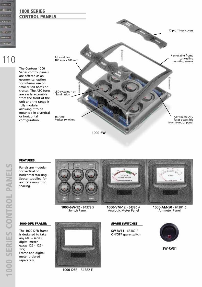
110
1000 SERIES CO
NTROL PANELS
The Contour 1000Series control panelsare offered as aneconomical optionfor interior use onsmaller sail boats orcruises. The ATC fusesare easily accessiblefrom the front of theunit and the range isfully modularallowing it to bemounted in a verticalor horizontalconfiguration.
FEATURES:
Panels are modularfor vertical orhorizontal stacking.Spacer supplied foraccurate mountingspacing.
1000-DFR FRAME:
The 1000-DFR frameis designed to takeany 600 – seriesdigital meter (page 125 - 126 -127). Frame and digitalmeter orderedseparately.
1000-6W-12 - 64379 SSwitch Panel
1000-DFR - 64382 E
SPARE SWITCHES
SW-RVS1 - 65380 FON/OFF spare switch
SW-RVS1
1000-VM-12 - 64380 AAnalogic Meter Panel
1000-AM-50 - 64381 CAmmeter Panel
All modules108 mm x 108 mm
LED systems – onillumination
16 Amp Rocker switches
Clip-off fuse covers
Removable frameconcealing
mounting screws
Concealed ATC fuses accessible
from front of panel
1000-6W
1000 SERIESCONTROL PANELS

111
1000 SERIES CO
NTROL PANELS
LIGHTSCABIN
STEREO
FANS FRIDGE
LIGHTS
GASVALVE
108mm (4.25")
108m
m (
4.25
")
96m
m (
3.8"
)
16mm (.6")
28mm (1.1")
1000 SERIESCONTROL PANELS
1000-6W
SET-1002 - 64384 JSET-1000 - 64383 G
FEATURES:
� Supplied with ATC fuses accessible from front cover� Square dimensions allow for modular mounting� Supplied with label sheet part no. SET-1000� Systems – on LED on each switch� Matching trim conceals mounting screws� 4 way and 6 way options available� An On/Off/Momentary switch is available for hornoperation. Ordered separately Part No. SW-RVS3
LABEL SHEETS FOR 1000 SERIES CONTROL PANELS
Mod. 1000-6W dimensions
SWITCHES FUSESMODEL VOLT
6 61000-6W-12V
PART No.
64379 S 12V DC
Supplied with switch panel Ordered separately

112
BATTERY DISTRIBUTION SWITCH
ESBATTERY DISTRIBUTIONSWITCHES
BEP MARINE BATTERY SWITCH TEST PROCEDURES (UL 1107)Continuous (1 hour) intermittent (5 minutes) and cranking (enginestarting – 10 seconds). The test is to determine the maximum currentthe switch can handle for the stated time, without the rear terminalsexceeding 100°C above the ambient temperature. The continuous andintermittent ratings are tested at 110% of specified ratings. All BEPswitches are tested independently to this specification by a 3rd partylaboratory.
701 BATTERY MASTER SWITCH - 63142 CThe 701 Contour Battery Master Switch offers a number of uniquefeatures. The highlights being the patented contour lock system,allowing it to be a stand alone unit, or locked together with otherswitches. The 701 also features a control knob which cannot beremoved whilst in the On or OFF position, however can be removed byswitching to an anti-clockwise 45° position. The control knob alsofeatures an interchangeable labelling system allowing a full range ofapplications Set-713 or Set-715 (page 116). The 701 also featuresremovable side plates on 4 sides for access of up to 1/0 cables. Plus arear cover insulating the rear terminals against any short circuitsensuring the switch meets ABYC requirements. The 701 can be eithersurface or recess mounted by cutting a 52 mm (2 1/16”) hole.
FEATURES:� Continuous rating: 275 Amp DC� Intermittent rating: 455 Amp DC� Cranking rating: 1250 Amp DC� Voltage rating: 48V DC� Operation: ON/OFF� Mounting: recessed or surface� Termination stud size: 2 x 10 mm (3/8”)� Dimensions: 69 x 69 x 75h mm (2.75 x 2.75 x 3h inches)� Tin plated copper studs and nuts� Ignition protected
701-PM PANEL MOUNT BATTERY SWITCHES - 65494 X Same specifications as 701 switch
701
701 - PM
701-KEY- 63930 ESpare PartRemovableknob
701 dimensions
Mod. 701 dimensions
Standard BEP interchangeable
label system(page 116)
Countersunkrecess for
surface mountapplication
Removablekey
Standard 52,4 mm (2 1/16”)
hole cut out

113
BATTERY DISTRIBUTION SWITCH
ES
720 HEAVY DUTY BATTERY SWITCH - 63174 SThe 720 Heavy Duty Battery Switch fits into the same contour lock system as used on thebattery distribution system. Rated at 600 Amp continuous and 2500 Amp cranking. It iswell suited to larger vessels. As with the 701 and 720 can be recessed or surfacemounted. The 720 uses the same style of self cleaning sliding contact as used in the 701.Also utilises the same label sheet as 701. Part Number 713 or 715 (page 116).
FEATURES:� Continuous rating: 600 Amp DC� Intermittent rating: 800 Amp DC� Cranking rating: 2500 Amp DC� Voltage rating: 48V DC� Operation: ON/OFF� Mounting: recessed or surface� Termination stud size: 2 x 12 mm (1/2”)� Dimensions: 102 x 102 x 90h mm (4 x 4 x 3.5h inches)� Tin plated copper studs and nuts� Ignition protected� Available in bulk only
720
Recessed hole cut out 85 mm(3.3”)
720-DP/B dimensions
720-DP/B DOUBLE POLE BATTERY SWITCH - 67806 AThis model has the same dimensions and features as the 720 battery switch.The 720-DP also meets the needs of vessels being built to survey requirementswhere positive and negative supplies must be isolated at the same time.
FEATURES:� Continuous rating: 400 Amp DC� Intermittent rating: 525 Amp DC� Cranking rating: 1500 Amp DC� Voltage rating: 45V DC� Operation: ON/OFF 2 poles� Mounting: recessed or surface� Termination stud size: 4 x 10 mm (3/8”)� Dimensions: 102 x 102 x 90h mm (4 x 4 x 3.5h inches)� Tin plated copper studs and nuts� Ignition protected� Available in bulk only
720-DP/B
700 EASYFIT Dimensions
700 EASYFIT
700 EASYFIT BATTERY SWITCH - 63672 JThe 700 Easyfit is ideal on those installations where switches need tobe recessed through varying thickness of panels. 700 Easyfit featuresan easily removable threaded ring allowing for panel thickness up to19 mm (3/4”). It uses the same features as the 701 with the removablekey 45° past the off position, labelled handle and a removable backcover covering exposed terminals to meet ABYC specifications. Theswitch can also be surface mounted offering a unique style comparedto other switches available on the market. The 700 Easyfit can easily beretrofitted in place of most European post and lever type switches.
FEATURES:� Continuous rating: 275 Amp DC� Intermittent rating: 455 Amp DC� Cranking rating: 1250 Amp DC� Voltage rating: 48V DC� Operation: ON/OFF� Mounting: recessed or surface� Termination stud size: 2 x 10 mm (3/8”)� Tin plated copper studs and nuts� 700-KEY spare Part Removable knob� Ignition protected
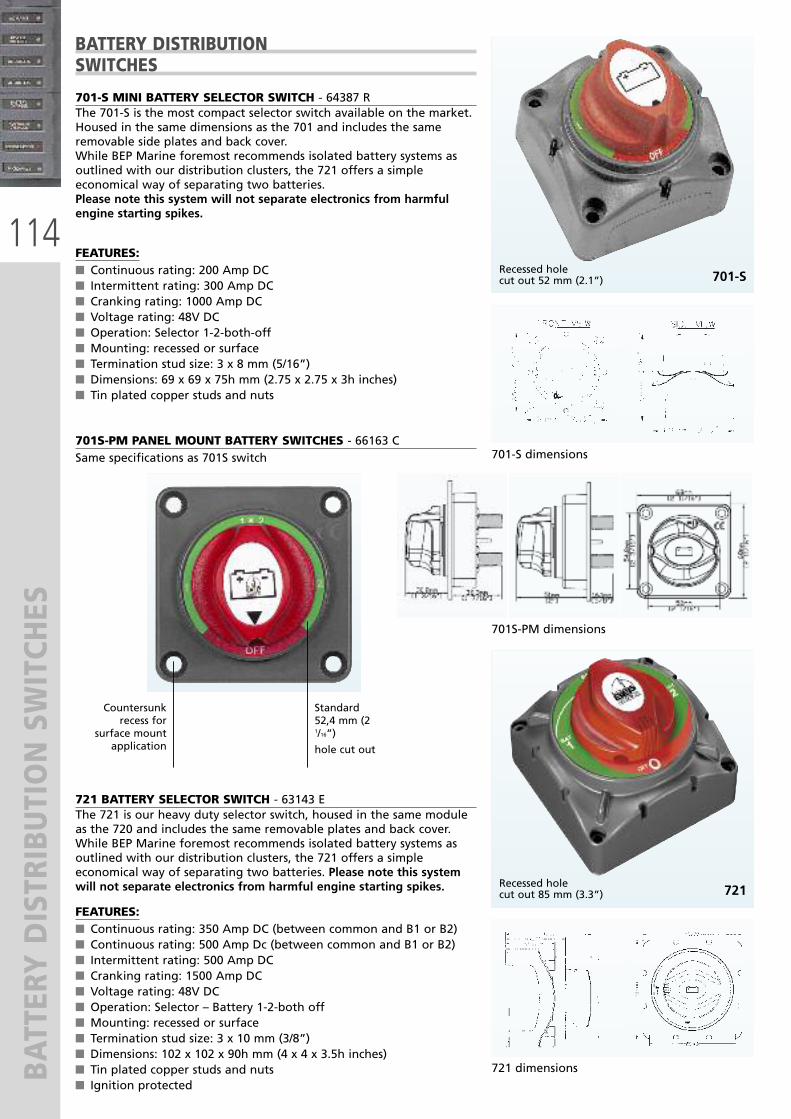
114
BATTERY DISTRIBUTION SWITCH
ES
701-S MINI BATTERY SELECTOR SWITCH - 64387 RThe 701-S is the most compact selector switch available on the market.Housed in the same dimensions as the 701 and includes the sameremovable side plates and back cover. While BEP Marine foremost recommends isolated battery systems asoutlined with our distribution clusters, the 721 offers a simpleeconomical way of separating two batteries.Please note this system will not separate electronics from harmfulengine starting spikes.
FEATURES:� Continuous rating: 200 Amp DC� Intermittent rating: 300 Amp DC� Cranking rating: 1000 Amp DC� Voltage rating: 48V DC� Operation: Selector 1-2-both-off� Mounting: recessed or surface� Termination stud size: 3 x 8 mm (5/16”)� Dimensions: 69 x 69 x 75h mm (2.75 x 2.75 x 3h inches)� Tin plated copper studs and nuts
721 BATTERY SELECTOR SWITCH - 63143 EThe 721 is our heavy duty selector switch, housed in the same moduleas the 720 and includes the same removable plates and back cover.While BEP Marine foremost recommends isolated battery systems asoutlined with our distribution clusters, the 721 offers a simpleeconomical way of separating two batteries. Please note this systemwill not separate electronics from harmful engine starting spikes.
FEATURES:� Continuous rating: 350 Amp DC (between common and B1 or B2)� Continuous rating: 500 Amp Dc (between common and B1 or B2)� Intermittent rating: 500 Amp DC � Cranking rating: 1500 Amp DC� Voltage rating: 48V DC� Operation: Selector – Battery 1-2-both off� Mounting: recessed or surface� Termination stud size: 3 x 10 mm (3/8”)� Dimensions: 102 x 102 x 90h mm (4 x 4 x 3.5h inches)� Tin plated copper studs and nuts� Ignition protected
721Recessed holecut out 85 mm (3.3”)
721 dimensions
701-SRecessed holecut out 52 mm (2.1”)
701-S dimensions
BATTERY DISTRIBUTION SWITCHES
701S-PM PANEL MOUNT BATTERY SWITCHES - 66163 CSame specifications as 701S switch
701S-PM dimensions
Standard 52,4 mm (21/16”)
hole cut out
Countersunkrecess for
surface mountapplication

115
BATTERY DISTRIBUTION SWITCH
ES
Due to the increased loading requirements on modern boats and largeincreases in the cost of copper battery cable, the MD range of batteryswitches allows you to mount the battery switch very close to thebattery, reducing cable lengths to starter motor. They are also ideal forremote isolation of bow thrusters.
THE MD RANGE OFFERS THE FOLLOWING FEATURES:� Remote operation (easier access for battery control).� Battery switch can be mounted alonside battery, reducing cable lengths and cable sizes to starter motor (large cost saving in copper cable).
� Reduced labour for fitting, due to shorter battery cabling.� Manual override option to meet CE requirements.� LED status identification for remote control switch.� Same capacity/specification and mounting options as standard BEPbattery switches.
� Utilize same interchangeable labelling system as BEP batteryswitches.
For the remote operation of the 701-MD and 720-MD battery switches,use the key switches 722-KS or 722-KS2 (page 116) or any standardon/off switch.
701-MD SPECIFICATIONS - 66026 S� Continuous rating: 275 Amp DC� Intermittent rating: 455 Amp DC� Cranking rating: 1250 Amp DC� Voltage rating: 9,5 – 32 Volt� Operation: On / Off� Mounting: recessed or surface� Ignition protected� Stud size: 2 x 10 mm (3/8”)� Tin plated copper studs and nuts
720-MD SPECIFICATIONS - 66027 U� Continuous rating: 500 Amp DC� Intermittent rating: 700 Amp DC� Cranking rating: 2500 Amp DC� Voltage rating: 9,5 – 32 Volt� Operation: On / Off� Mounting: recessed or surface� Ignition protected� Stud size: 2 x 12 mm (1/2”)� Tin plated copper studs and nuts
720-MD
701-MD
701-MD dimensions
720-MD dimensions
REMOTEOPERATED BATTERY SWITCHES
720 - MD
WIRING DIAGRAM

116
BATTERY DISTRIBUTION SWITCH
ES
KEY SWITCHES FOR BATTERYDISTRIBUTION SWITHCES
722-KS2 - 63215 D
722-KS 65350 W
LABEL SETS FOR BATTERYDISTRIBUTION SWITCHES
Set - 713 Set - 71563681 K 64389 V
+ -
HOUSE
+ -
STBDSTART
INVERTER
+ -
START
+ -
GENSET
+ -
1
WINCH
CHASSIS
EMERGPARALLEL
BOWTHRUSTER
+ -
PORTSTART
+ -
2
+ -
MIDSTART
+ -
RADIO
+ -
HOUSE
+ -
START
EMERGPARALLEL
All 701 and 720 switches come
standard with thebattery symbol label.In installations wheremultiple switches are
used, it will benecessary to label theswitches for different
application.
Set 715 contains thethree most commonlyrequested labels outof Set 713 withoutthe need to purchase
a full label set.
For remote operation of the 701-MD and 720-MD battery switches.Compatible for remote operation of 701-MDVS and 720-MDVS VoltageSensitive Relays too.
WIRELESS REMOTE CONTROL AND RECEIVER TO OPERATE BATTERY SWITCHESYou can now wire your Battery to the BEP receiver and operate the On/Offswitch by remote control, from a distance of up to 50 metres away
� You can control up to 4 separate 5 Amp circuits, eg. 701/720-MD batteryswitches, anchor light, navigation lights and courtesy lights
� No more lifting hatches to turn on battery switches – it is now all controlledfrom your remote keyfob
� Control battery switches easily (On/Off) from the dock or carpark� The remote has a rolling code, for your security
80-911-0045-00 - 66951E - Wireless remote control

117
VOLTAGE SENSITIVE RELAYS
The VSR switch utilizes the same operation as the MD battery switchesand is packed with features which complimet the MD range.
FEATURES
� Dual battery sensing� Remote emergency parallel function 701-MDVS and 720-MDVS canbe operated through a momentary button on the dash which willparallel the batteries for a present time of 10 minutes. Once this 10minutes has passed, if the voltage is up high enough for the voltagesensitive switch to operate, it twill stay engaged. If not, it willdischarge.
� Engine run sensing VSR will engage when the voltage on either startor house battery reaches 13,7 Volt. If the combined battery voltagedrops below 13,0 Volt and the engine is not running, after 5seconds the contacts will open and stay open until the start orhouse battery voltage exceeds 13,7 Volt. If the combined batteryvoltage drops below 12,2 Volt and the engine is running, after 5minutes the contacts will open and stay open until the start orhouse battery voltage exceeds 13,7 Volt. If voltage drops below 13,0Volt and stays above 12,2 Volt on either start or house battery whileengine is running, the VSS will stay engaged.
� Manual override option� The VSR will cover your dual battery charging requirements andemergency parallel operation in one unit
720-MDVSSame specifications
as 720-MD
701-MDVSSame specifications
as 701-MD
MODEL
701-MDVS
720-MDVS
701-MDVS-24V
720-MDVS-24V
PART No.
66416 F
66417 H
66418 K
66419 M
VOLT
12V DC
12V DC
24V DC
24V DC
RATING
275A
500A
275A
500A
ENGAGES
13.7V DC
13.7V DC
27.4V DC
27.4V DC
DISENGAGES
12.2-13.00V DC
12.2-13.00V DC
24.4-26.00V DC
24.4-26.00V DC
REMOTE OPERATEDDUAL BATTERY CHARGINGVOLTAGE SENSITIVE RELAYS(VSR)WIYH EMERGENCY PARALLEL

118
VOLTAGE SENSITIVE RELAYS
710-125A VOLTAGE SENSITIVE RELAYThe VSR (Voltage Sensitive Relay) allows two or more batteries to becharged at the same time. The relay stays open when the engine isfirst started and remains open during charging until the battery hasreached a preset voltage (13.7V). The relay then closes, allowing thetwo batteries to be charged together. When the engine is stopped, thevoltage returns to normal levels, which allows the relay to open again,separating the 2 batteries, eliminating the possibility of dischargingthe wrong battery.
ADVANTAGES OF FITTING VSR’S OVER CONVENTIONAL CHARGE(DIODE ISOLATORS):� Easy 3 wire connection at the battery. No need to bypass existingalternator wiring.
� VSR’s have no volt drop. Conventional diode isolators incur aminimum of 6 volt drop.
� Compact size - no large heat sink.
710-125A-DS (DUAL SENSE) VOLTAGE SENSITIVE RELAY Same as the 710-125A with the added feature of dual sensing. Thisallows the unit to sense the voltage of both batteries that it isconnected between. If either battery is receiving a charge the VSR willactivate paralleling the two battery banks. The 710-125A-DS is designed for situations where a battery charger orsecond charging source is used into the house battery.
� Ignition protected
DUAL BATTERY CHARGINGVOLTAGE SENSITIVE RELAYS
710-125A
710-125A-DS
Red LED indicatescombined charge mode
APPLICATION
For use on charging systems up to: 125 Amp
MODEL
710-125A
SIZE mm (“)H x W x D
69 x 69 x 50 (2.75 x 2.75 x 2)
For use on charging systems up to: 125 Amp710-125A-DS 69 x 69 x 50 (2.75 x 2.75 x 2)
PART No.
64390 D
65351 Y
VOLT
12V DC
12V DC
For use on charging systems up to: 100 Amp710-100A-24V 69 x 69 x 50 (2.75 x 2.75 x 2)65381H 24V DC

119
BATTERY DISTRIBUTION CLUSTERS
716-SQ-100 AVSR
715-S
717-100A
716-SQ-100AVSR DUAL BATTERY CHARGING CLUSTERSFor use on charging systems up to 125A. To be used on followingsystems:� Single outboard dual battery bank� Single alternator inboard engine dual battery bank
715-S DUAL BATTERY CHARGING CLUSTERSThe 715-S is designed for systems with twin engines and 2 batteries.The house loads can be switched between port and starboard battery. The selector switch can also be used to parallel the batteries when inboth position.
717-100A THREE BATTERY CHARGING CLUSTERS This system is designed for twin outboard installations using outboardswithout AUX outputs. It will allow the port engine to charge the portstart battery and the house battery when the VSR is engaged. It willalso allow the starboard engine to charge the starboard start batteryand the house battery when the starboard VSR is engaged, giving acombined charge from two outboards into the house battery until thevoltage regulators on both engines control the charge. It will alsoallow the house battery to be charged if steaming on one engine.
BATTERY DISTRIBUTION CLUSTERS
716-SQ-100 AVSR 717-100A
ENGINE/BATTERIES
Single inboard or outboard engine/2 banks
MODEL
716-SQ-100AVRS
SIZE mm (“)H x W x D
138 x 138 (5.4 x 5.4)
Twin inboard or outboard engine/2 banks715-S 138 x 69 (5.4 x 2.75)
Twin outboard engine/3 banks
ORIENTATION
SQUARE
RECTANGULAR
RECTANGULAR717-100A
PART No.
64391 F
65352 A
65353 C 207 x 138 (8.1 x 5.4)

120
REMOTE BATTERY MANAGEM
ENT SYSTEM
80-716-0015-00
80-700-0051-00
SYSTEM FOR DUAL ENGINE AND THREEBATTERIES 80-716-0015-00 - 67404 DIt offers the same features as the system717-100A, but totally motorized.VSR and battery switch are in one kit.
BATTERY SWITCHCONTROL CENTER (BCC) - 67405 FSophisticated electrical systems need reliableautomation.It is possible to centralize power handlingwith BEP Battery Control Center (BCC)that can control all battery switches from oneconvenient position.
FEATURES
� The BCC is equipped with locks that ensuresgroup operation at the turn of the key. Anyswitch can be isolated cy disengaging itslock and toggling the switch off
� Isolate each battery via key switch ordesignated battery banks via breaker.
� LED Status indicators for battery switchstatus.
REMOTE BATTERYMANAGEMENTSYSTEM
Dimension guideClusters are made from uniformly squareswitches. Each side 69 mm (2.7”)

121
BATTERY DISTRIBUTION COMPO
NEN
TS
4531011
703-500A
4531001
GALVANIC ISOLATORS
� Prevent galvanic corrosion due to dissimilar metals between boats� Gold plated terminals provide superior corrosion resistance tomarine environment
� Block DC current from flowing through shore power cable� Ignition protected
BATTERY DISTRIBUTION COMPONENTS
702 DISTRIBUTION STUDThe 702 Contour Distribution Stud allows terminating of heavy dutycables for 1 or more connections. Contour lock housing has removableside plates which allow for connections from all sides, utilising linkbars 702SB.
702SB
702SBSecondary BusFitted to distributionstud 702 allows forsmall wireconnections withoutcluttering main stud.Terminal screws 4mm (1/8”).702 702SB - 64393K
MODEL
702
SIZE mm (“)H x W x D
69 x 69 x 50 (2.75 x 2.75 x 2)
703-200A
PART No.
63687 Y
64185 C 138 x 69 x 50 (54 x 2.75 x 2)
703-500A 63688 A 69 x 69 x 50 (54 x 2.75 x 2)
AMP
30A
MODEL
4531001
VOLTAGE
115/230V
50/60A4531011
PART No.
67078 T
67079 V 115/230V
STUD SIZE
10 mm (3/8”)
AMP
200A
10 mm (3/8”)
10 mm (3/8”)
200A
500A
BUS BARS Marine grade negative or positive Bus Bars are supplied as standardwith all BEP AC/DC control panels
FEATURES:
� 4 mm (5/32”) stainless steel screws with shakeproof washers� 2x6 mm (1/4”) input stud� Tin plated brass� Insulated mounting base
FEATURES:
� Tinned copper 10 mm (3/8”) orbrass studs 6 mm (1/4”)with spring washers
� High temperature plasticinsulated mounting base
DIMENSIONS W x H x D mm (“):
� IS-10MM-1: 44x35x18 mm(1.73x1.37x0.7)
� IS-6MM-2: 42x32x36 mm(1.65x1.25x1.42)
INSULATED STUDS
BB-6W-2S
BB-12W-2S
BB-24W-2S
OUTPUT SCREWS4 mm (5/32”)
6
INPUT STUDS6 mm (1/4”)
1
MODEL
BB-6W-2S
CURRENTRATING100A
12 1BB-12W-2S 100A
24 2BB-24W-2S
PART No.
63690 L
63691 N
63692 R 150A
IS-10MM-164392H
IS-6MM-263689C

122
BATTERY DISTRIBUTION COMPO
NEN
TS 704-ANL FUSE HOLDER HEAVY DUTY - 63235KThe 704-ANL allows fusing of heavy duty accessories between 80 Amp -500 Amp. Mounted in contour lock mouldings with removable sides.Meets ABYC standards for exposed terminals.
704-ANL
ANL-FUSE704-ANLFuse
viewing window
ANL FUSE LINKS
80 Amp
MODEL
IP80A
100 AmpIP100A
150 Amp
SIZE mm (“)H x W x D
138 x 69 x 50 (5.4 x 2.75 x 2)
IP150A 138 x 69 x 50 (5.4 x 2.75 x 2)
138 x 69 x 50 (5.4 x 2.75 x 2)
200 AmpIP200A
250 AmpIP250A
300 Amp
138 x 69 x 50 (5.4 x 2.75 x 2)
138 x 69 x 50 (5.4 x 2.75 x 2)
138 x 69 x 50 (5.4 x 2.75 x 2)IP300A
425 AmpIP425A
500 Amp
138 x 69 x 50 (5.4 x 2.75 x 2)
138 x 69 x 50 (5.4 x 2.75 x 2)IP500A
PART No.
64394 M
64395 P
63806 D
63807 F
63808 H
63809 K
63810 U
64407 U
IGNITION PROTECTED
BATTERY DISTRIBUTION COMPONENTS
702-MFH AND 702-HDBFH SINGLE FUSE HOLDER BEP Marine’s new heavy duty fuse holders are an economical way offusing heavy loads 30-80 amp. Ideal for battery charger outputs ormains feeds. 6 mm (1/4”) studs receive ring terminals and cables up to25 mm2 (4 gauge). Fuse is clamped between tinned brass clamp forpositive connection. Covers enclose exposed terminals to meet ABYCstandards.
702-MFH
STUD SIZE
6 mm (1/4”)
MODEL
702-MFH
SIZE mm (“)H x W x D
71 x 53 x 36 (2,8 x 2 x 1.42)
6 mm (1/4”)702-HDBFH
PART No.
67406 H
65354 E 69 x 69 x 50 (2,75 x 2.75 x 2)
RATING
30 Amp
MODEL
BFHD-30A
40 Amp BFHD-40A
50 Amp
PART No.
66132 R
66133 T
66134 VBFHD-50A
RATING
60 Amp
MODEL
BFHD-60A
70 Amp BFHD-70A
80 Amp
PART No.
66135 X
66136 Z
66137 BBFHD-80A
HEAVY DUTY FUSESSPECIFICATIONS:- Fuses available 30-80 Amp - Interrupt capacity: 1000 Amp DC - Maximum voltage: 32 Volt DC

123
ATC FUSE HOLDERS
ATC-6W
BB-LINK - 26 mm
J05A
DESCRIPTION
6 way fuseholder, screw terminals, with cover
MODEL
ATC FUSE HOLDERS
ATC-6W
RATING
3 Amp
MODEL
ATC FUSES
J03A
5 Amp J05A
7.5 Amp J7.5A
10 Amp J10A
15 Amp J15A
20 Amp J20A
25 Amp J25A
30 Amp J30A
PARTNo.
66018 T
66019 V
66020 D
66021 F
66022 H
66023 K
66024 M
66025 P
6 way fuseholder, quick connect, with coverATC-6WQC
PART No.
65569 C
66017 R
The BEP ATC fuse holder includes thepatented contour lock system (as used in allBEP battery management products). Thisallows you to module as many fuse holders asyou like together.The advantage of this is that it allows you tolink the inputs together, or split them apart toallow multiple power groups within one fuseholder: eg. switched supply or 24 hour supply.For the aftermarket the modular systemallows you to carry one part number insteadof 3 or 4. The 6W-ATC also includes a clip oncover and label positions. The lebel positionsreceive the same label as the 1000 seriespanels: refer page 111 (ordered separately).
SPECIFICATIONS� Maximum amperage per circuit: 30 Amp� Maximum amperage per block: 100 Amp� Maximum voltage: 32V DC� Base material: polycarbonate� Cover material: clear polycarbonate
SPECIFICATIONS� Fuses available: 3-30 Amp� Interrupt capacity: 1000 amp DC� Maximum voltage: 32 Volt DC
ATC FUSE HOLDERS
Clip on coverwith label
position foreach fuse
Position for spare fuses
Fuse holder linkPart No. - 65570 LBB-LINK-26 mmOrderedseparately
Available with screw terminal
or 6,3 mm QuickConnect options
(see part numbersbelow)
J05A dimensions
ATC-6W Dimensions

124
DIGITAL MONITORING SYSTEM
S
80-600-0021-00
DCSM SYSTEM INCLUDES 1 X SHUNT AND CABLE 80-600-0021-00 - 67407 K
DC SYSTEMS MONITOR (DCSM)
80-600-0023-00
DC POWER METER:
� Displays voltages of multiplebattery banks (0-32VDC)
� Displays charge and discharge(Amps) of 2 battery banks
� Displays battery capacity in A/h
� High/Low level alarms
DISPLAY TYPE:
� Configure the DCSM to showthe data in analogue, digitaland graphic form
CIRCUIT STATUS:
� View the status of importantcircuit (on/off) in graphic andnumeric form
TANK LEVEL:
� View tank level informationfor multiple tanks in numericand graphic forms. Resetablewhen leaving boat.
MONITORS:
� Charge/discharge (Amps)for two banks
� Capacity remaining inA/h and %
� Battery condition� Tank fluid level� Circuit status
FEATURES:
� 8 generic, userconfigurable inputs
� Programmable high/lowaudio/visual alarms forvolts, amps and tanklevels
� Backlit keypad anddimmable screen
� Can be panel or surfacemounted
SPECIFICATIONS:
� 2.8” colour QVGA LCD� Input voltage: 8-32VDC� Dimensions: W 38mm(1,50”) x H 40mm (1.57”)
� Backlit keypad
ACSM SYSTEM INCLUDES 1 X AC-VSEN-4 AND 2 X CT-10-3 80-600-0023-00 - 67408 M
AC SYSTEMS MONITOR (ACMS)
AC POWER METER:
� Displays AC volts, ampsfrequency and power for twosupplies with a third positionfor monitoring AC volts andfrequency of a third supply
� Displays AC power in kW
AC VOLTS/FREQUENCY:
� Displays AC voltage andfrequency, 80-264 Vac 50 & 60Hz
AC AMPS:
� Displays current for 2 x ACsupplies (0-75A)
ALLARMS:
� High and low alarms for eachinput
� User selectable alarm levels� Mutable
MONITORS:
� AC volts, amps andfrequency
FEATURES:
� 3 generic userconfigurable inputs
� Displays data inanalogue, digital andgraphic forms
� Programmable high/lowaudio/visual alarms foreach input
SPECIFICATIONS:
� 2.8” colour QVGA LCD� Input voltage: 8-32VDC� Dimensions: W 38mm(1,50”) x H 40mm (1.57”)
� Backlit keypad

125
DIGITAL MONITORING SYSTEM
S
The 600 series Digital Monitoring System, designed and manufactured by BEP Marine, is made to meet the requirements of modernboating and recreational vehicles. Electrical installations on-board the modern boat now incorporate complex AC and DC systems alongwith extensive tankage for items such as fuel, fresh water, sewage and grey water. Accurate monitoring of such systems is essential, as amal-function in any one of the above areas could cause major damage to expensive equipment and ultimately endanger the vessel orpeoples lives. The dot matrix display incorporated in the 600 series allows for more detailed on-screen information and clarity ofviewing. They have a backlighting display for easy night time viewing, audible alarm with mute function, power supply 10-35V DC.The Contour Matrix series is designed to be surface mounted or recessed into a panel utilising the 600-PMK Kit.
600-DCM MONITOR - 63168XThe 600-DCM monitor offers a comprehensive range of functions toallow full monitoring of your batteries and charging system.There is also a function allowing for 24h monitoring of your bilge. This meter is an important addition to modern battery managementsystems.
Capacity remaining in Amp hours and percentage
LB-450-50 SHUNT - 64396 S450A - 5 Shunt supplied with 600-DCM monitor
DIMENSIONS WxDxH mm (“):
� 83 x 45 x 44 (3.26 x 1.77 x 1.73)
VOLTAGE MONITOR:
� Voltage monitor for up to3 battery banks
� 12 costum selectablelegends eg: Start battery,House battery etc.
� Hi / Low voltage alarms onall 3 banks
AMP CHARGE & DISCHARGE:
� On house bank only� Meter supplied witha 450-50 mV shunt
PERCENT REMAININGIN AMP HOURS:
� Software utilizes Peukertsexponent
� Suitable for use on batterybanks from 60 to 3000Amp hours
� Low Amp hour alarm
BILGE MONITOR
� The bilge monitor functionmonitors bilge pump functions24 hours, 7 days a week. Storesbilge pump operations andaccumulated time. Resettablewhen leaving boat.
� Function only available whenthird voltmeter position is notused
600-DCM
LB-450-50-SHUNT
CONTOUR MATRIX DIGITAL MONITORING SYSTEMS
SIDE VIEWSURFACEMOUNTED
SIDE VIEWREAR
MOUNTED
SIDE VIEW FRONT VIEW METER REAR VIEW
CONNECTOR STRIPMOUNTED IN
REMOVABLE PLUG FOREASY INSTALLATION
PANEL MOUNTING KIT AVAILABLE. INCLUDES FACIA, FASTENINGS AND TEMPLATE. P.N. 600-PMK - 65177 J

126
DIGITAL MONITORING SYSTEM
S600-ACM - 63169 Z The 600-ACM AC monitor includes one extra voltage input allowingmonitoring of twin line inputs. Selectable legends allow labelling e.g.AC volt Line 1, AC volt Line 2. It has also an extra input for currentenabling monitoring of Amp on twin line systems.
AC VOLT FUNCTIONS:
� 3 inputs with selectablelegends: AC volt Line 1,AC volt Line 2,AC volt L1 + L2,
� High / low volt alarm
AMP FUNCTIONS:
� 2 AC Amp inputs Selectablelegends:AC Amp, AC Amp Line 1 &AC Amp Line 2
� High Amp alarm
FREQUENCY FUNCTIONS:
� 0 – 100 Hz� Frequency alarmselectable for 50 or60 Hz
600-ACM
600-VM3 - 66567 D� Voltage monitoring on up to 3 battery banks� Custom selectable legends e.g. Start batt, House batt� High / low voltage alarms� Input 10 – 35V DC
600-VM3
AC-VSEN - 64397UThe AC-VSEN includes 2 voltage transformersfor 2 voltage inputs. Supplied with 600-ACM.
AC-VSEN-4 - 67314 CAC transducer supplied with ACSM system
AC-VSEN
CT-10-3 - 64398WOne Ct-10-3 current transformer is supplied with 600-ACM. If a twinline system is in use a second CT must be ordered.
CT-10-3
DIGITAL MONITORING SYSTEMS
AC-VSEN-4

127
DIGITAL MONITORING SYSTEM
S
DIGITAL MONITORING SYSTEMS
600-TLM-N
TANK MONITORING SYSTEM 600-TLM-N - 63171 K The Contour Matrix Tank Monitoring system (600-TLM-N) offers full monitoring up to three tanks. A 600-TLM-SIF interfacemodule must be used when using standard European (10-180 Ohm) senders or American (240 - 33 Ohm) senders toproduce a 0 - 5 V signal to operate 600-TLM-N system. One 600-TLM-SIF interface module must be used for each sender.
FEATURES
� Monitoring for up to 3 tanks� 14 selectable legends for tankdescriptions, ex. Fuel, Water,Blackwater
� High/Low level alarms for 3 tanks� Graphic or percentage display� Backlit display for night viewing� Audible alarm with mute
SPECIFICATIONS:
� Litres, imperial or US gallons� Power supply 10-35VDC� Interfaces directly withpre-calibrated TS1 Sender(0-5V output – pag. 130)
� If fitting an uncalibrated TS1sender, calibration can be done onsite within the 600-TLM-N meter.
SINGLE OR MULTI-TANK DISPLAY
600-TLM-SIF - 63172 MThe 600-TLM-SIF tank sender interface module must be used whenusing standard European (10 – 180 Ohm) or American (240 – 33 Ohm)senders to produce a 0 – 5 Volt signal to operate 600-TLM. 10 – 32V supply. One unit per sender required.
ANALOG STAND-ALONE METERS
AMMETER SHUNT
N816DCV
600-TLM-SIFDimensions: 60 x 34 x 22h mm(2.4” x 1.3” x 0.9”h)
VOLT
12V DC
MODEL
ANALOG VOLTMETERS
N816DCV
SCALE
8-16 Volt DC
24V DCN1632DCV
PART No.
63682 M
63683 P 16-32 Volt DC
SCALE
0-50 Amp DC
MODEL
ANALOG AMMETERS
N050A
CURRENTTRASFORMER
N/D
0-100 Amp DCN100A N/D
SHUNTMODEL
50A-50MV
100A-50MV
0-150 Amp DCN150A
PART No.
64399 A
64400 D
64183 Y N/D 150A-50MV
SCALE
0-50 A
MODEL
AMMETER SHUNT
50A - 50MV
0-100 A100A - 50MV
0-150 150A - 50MV
PART No.
64515 X
64178 F
64516 Z

128
CZONE™
CZone™ is what you want in a digital controlsystem designed for manufacturers andinstallers.
It semplifies installation of electrical systemsthrough the replacement of complicated,cumbersome wiring to switch and fuse panels,with state of art, robust interface and lightNMEA 2000 network cable.
INSTALLATION:
Builders recognize an immediate benefit withreductions in cable usage, harness weightsand installation times. CZone™ decentralizesthe DC power distribution system, locatescircuit control and protection modules closerto loads to shorten cable runs and reduce thesize of conductors, significantly decreasing thecost and weight of the electrical wiringharness. The system replaces complex wiringwith a single data wire. Integrated diagosticsensures fault finding is simple and modulescan easily be added into the system.
INTEGRATION:
CZone™ is NMEA 2000 compliant and usesstandard Micro cables and connectors. Thisallows a single network backbone to beinstalled for multiple systems (CZone™ andother NMEA 2000 devices). Additionally,CZone™ can share certain monitoringfunctions with other NMEA 2000 compliantscreens.
SECURITY AND VERSATILITY:
CZone™, designed for 9-32V systems, featuresbuilt-in timers, dimmers (incuding support forhalogen lighting), alarms, voltage reducersand load shedding.The No-Single-Failure-Point techonologyensures a plug-n-play system that is designedto handle mishaps. If a module is damaged,the system will autoatically program thereplacement module, when it is plugged in.
NETWORK CONTROL AND MONITORING SYSTEM
DISPLAY INTERFACE

129
CZONE™
NETWORK CONTROL AND MONITORING SYSTEM
DISPLAY INTERFACEThis module is the interface betweenthe CZone™ network and the user. Itoffers full control of circuits as well asthe ability to view important on boardsystems information such as tank levelsand power levels. It also providesaudible and visual alarms. For instance,“night running” mode turnspre-selected lights on to dim levels.
METER INTERFACEThe Meter Interface accepts inputs fromexternal AC and DC power meteringsensors. It processes and converts theanalog signal into digital string that can bepresented, by the display, to the user as oneof several formats such as: Ac and DCvoltage and amps, DC battery capacity inamp hours and % remaining. All with userdefinable high and low alarms.
SIGNAL INTERFACEThe Signal Interface connectsCZone™ to your external sensors,alarms and switching devices. Forexample, it can be easilyprogrammed to allow a fluid transferpump and an alarm to turn onsimultaneously when it detects that alow tank level has been reached.
SWITCH CONTROL INTERFACEThe Switch Control Interface providesan interface between the CZone™network and traditional mechanicalswitches. This interface converts thesignal from those switches into CANsignal needed across a digitalnetwork.
OUTPUT INTERFACEThe Output Interface provides anintelligent replacement fortraditional circuit breaker and fusepanels. It can be installedeverywhere on boat.
MOTOR OUTPUT INTERFACEThe Motor Output Interface has anoutput pair for controlling DC motorswhich require a reversal of polarity tochange the direction of their mechanicaloperation, for example a DC motor foran electric window mechanism. It can beconfigured to deliver a “soft start”.

130
ULTRA
SONIC TANK SEN
DER
TS1 - 66322 WThe TS1 Ultrasonic Tank Sender can be used on fuel (petrol or diesel), fresh water, grey or black water tanks.One part number suits all tanks!
SPECIFICATIONS:
� The TS1 is programmable for the following outputs: 240-33 Ohm, 10-180Ohm and 0-5 Volt
� The TS1 offers low profile and standard SAE 5 hole mounting pattern,allowing it to be retrofitted to practically all other sender brands
� The TS1 can be programmed for tank dimensions via a computer utilizingBEP Marine’s proprietary TS1 software and TS1-PK kit software avoidingexperimental tank filling on site
� The TS1 configured to a 0-5V output will connect straight into the BEP600-TLMN and 600-DCTLM digital tank monitors
� When configured to a 240-33 Ohm or 10-180 Ohm output the TS1 can beconnected to Uflex®, Wema®, Faria®, VDO®,Teleflex® and many otherpopular instrument brands. When connecting to non-adjustable gaugesthe TS1 must be pre-calibrated
� Standard off the shelf TSI sender is set for 0-2000 mm (6.5’)
ULTRASONIC TANK SENDER
Non linear Tank Parameter Calcutation
TS1
0,5 m (1.6’) cable
BEP Marines proprietary software allows distributors or volume users topre-programme tank dimensions giving accurate measurement avoidingexperimental tank filling.
low profile
TS1-PK - 66323Y
SPECIFICATIONS
Current draw 10-32VDC
Currentdraw
25mA with 5 volt gauge output
Measurementmethod
acoustic sonic measurement
Tank depth 0 to 2000mm (6.5 ft)
Accuracy distance 0-2000mm (6.5’) at 2 mm accuracy
Mounting SAE 5 stud mounting
pattern with gasket, seal and screws. Top mount only
Environmental temperature 4 to 65 degrees C
Chemical resistance Petrol, diesel, water, toilet chemicals
Tank type Metal and plastic with non linear capacity, grey and blackwater, petrol and diesel

131
SHORE POWER SYSTEM
S
QUALITY MARINE ELECTRICAL PRODUCTS
SHORE POWER SYSTEMS

132
SHORE POWER SYSTEM
SSHORE POWER FEATURES
EASY LOCK™ SYSTEM
Marinco’s exclusive Easy Lock System has beendesigned to make hook-up quick and easy. Justconnect the cordset (with an Easy Lock locking ringinstalled) to the inlet and turn the locking ring lessthan a quarter turn.The tabs on the locking ring lock into the inlet fora positive watertight hook-up while eliminatingany chance of cross threading. The locking ringfeatures lock locators positioned at 180° to improvefinger grip during attachment.Easy Lock inlets have a threaded boss that willaccept threaded cordsets as well.
SOFT TOUCH™ CAP DESIGNMARINCO inlets feature the Soft Touch cap design.The Soft Touch hinge is designed with a special camfeature that allows it to stay “locked” open in theupright position during hook-up. A “soft touvh”unloks it for closing.
PowerCord PLUS® CORDSETThe PowerCord PLUS® has features you will notfind on other cordsets.
Power Indicator lightLED Power indicator light – lets you know if youhave power
Comfort Grip with Thumbprint LocatorMoulded to fit the contour of your hand.Thumbprint Locator lines up the locking blades forquick and easy connections.
- LED Power Indicator Light- Contour Grip Ends- Thumbprint Locator- Super Flexible 10/3 Cable- Easy LockTM System- High Quality Marine Grade Construction- Watertight Molded Plug & Connectors- Includes threaded ring and Easy Lock ring- All PowerCord PLUS cords assembled completewith Watertight Connector Cap to ensure CEcompliance
- CE marked

133
SHORE POWER SYSTEM
S
16 Amp/220V & 32 Amp/220V SHORE POWER PRODUCTS
� 316 Stainless Steel� Easy Lock System� Soft Touch cap design� Rear safety enclosure with strain relief
303SSEL-BX - 66753A - 16A6371EL-BX - 66766K - 32A
� Glass-filled polyester� Easy Lock System� Watertight� Rear safety enclosure withstrain relief
301EL-BX - 66754C -16A6351EL-BX - 66767M - 32A
� Glass-filled polyester� Easy Lock System� Watertight� Rear safety enclosure w/strain relief
304EL-BX - 66755E - 16A 6343EL-BX - 66768P - 32A
� Glass-filled polyester� Chrome plated cover � Easy Lock System� Watertight� Rear safety enclosure 6343EL-BXCR – 66769S - 32A
16 Amp/220V & 32 Amp/220V 50 HZ - POWER INLETS
� Female Connector� Corrosion resistant contactsand terminals
305CRCXN - 66757J - 16A6360CRNX - 66770A - 32A
� Weatherproof Cover withthreaded ring
� Use with female connectors103RNX - 66758L - for 16A7715CRNX - 66771C - for 32A
� Watertight Connector Sealing Cap
� Use with cover andconnector to ensure CE compliance
199109 - 66759N - for 16A199110 - 66772E - for 32A
16 Amp/220V & 32Amp/220V - FEMALE CONNECTORS
� PowerCord™ Cordset� 3,3 mm² (12/3)� With Female connector� Blunt cut male end50PCMX - 66760X - 15,24 m (50 ft)25PCMX - 66761Z - 7,62 m (25 ft)
� PowerCord ™ PLUS Cordset� 3,3 mm² (12/3)� With moulded connectorwith LED power indicatorlight
� Blunt cut male end50SPPX - 66762B - 15,24 m (50 ft)
� PowerCord ™ PLUS Cordset� 2,5 mm² (10/3)� With moulded connectorwith LED power indicatorlight and IEC 60309 maleplug (IP44)
� Watertight connectorsealing cap for CEcompliance
20MSPPXP - 66763D - 20 m (65.6 ft)15MSPPXP - 66764F - 15 m (49.2 ft)10MSPPXP - 66765H - 10 m (32.8 ft)
16 Amp/220V 50 HZ - SHORE POWER CORDSETS
� PowerCord ™ PLUS Cordset� 3,3 mm (12/3)� With moulded connectorwith LED power indicatorlight and IEC 60309 maleplug (IP44)
� Watertight connectorsealing cap for CEcompliance
15M32AXP – 66773G - 15 m(49.2 ft)
32 Amp/220V 50 HZ - SHORE POWER CORDSET
� Includes 6 Cable Clips withstainless steel mountingscrews
� Keeps shore power cableout of the water
� Holds 10 gauge 30A cable� Easy to install� Use on deck or edge ofdock
� Organize shore power cableCLIP – 66825 Z
CABLE CLIP

134
SHORE POWER SYSTEM
S50 Amp 125V/250V; 3 POLE, 4-WIRE SHORE POWER PRODUCTS
� Solid cast 316 stainless steel� Easy Lock System� Soft Touch cap stays openin the upright position
� Rear safety enclosure withstrain relief
� Locking waterproof cap6373EL-B – 66774J - 50A
� Same as 6373EL-B powerinlet, without rear safatyenclosure
6373EL - 66776N - 50A
� Glass-filled polyester� Easy Lock System� Watertight cap� Rear safety enclosurew/strain relief
� Marine stainless steel trim6353EL-B – 66775L - 50A
� Glass-filled polyester� Easy Lock System� Soft Touch cap stays openin the upright position
� Chrome finish cover� Rear safety enclosure� Stainless steel trim 6344EL-BCR – 66777R - 50A
50 AMP 125V/250V; 3 POLE, 4-WIRE - POWER INLETS
� Male Plug ribbed, thick wallnylon housing for securegripping
� Use with weatherproof7717N cover for superiorseal
6365CRN – 66778T -50A
� Weatherproof cover formale plug 6365CRN
7717N – 66822T
� Female connector ribbed,nylon housing for securegripping
� Use with weatherproof7715CRN cover for superiorseal
6364CRN – 66779V - 50A
� Weatherproof cover forfemale connector 6364CRN
7715CRN – 66771C
50 Amp 125V/250V; 3 POLE, 4-WIRE - MALE PLUG AND FEMALE CONNECTOR
� PowerCord ™ PLUS Cordset � LED power indicator light – lets youknow if you have power
� Watertightmolded plug and connectorfor safety and durability
� Contoured grip ends with ThumbprintLocator for fast and esasy connection
� Includes Easy Lock Ring and astandardthreaded ring for hook-up to ordinarythreaded inlets
6152SPP – 66783K – 15,24 m (50 ft)6152SPP-25 – 66784M– 7,62 m (25 ft)
� Locking with Sealing Collar System510R
165AY – 66781F – 50A
� Provides maximum moisture protectionbetween cordset and adapter.
510R – 66782H
110R – 67056G
50 Amp 125/250V; 3 POLE, 4-WIRE
SHORE POWER CORDSET
“Y” ADAPTER SEALING COLLAR WITH THREADED
RING
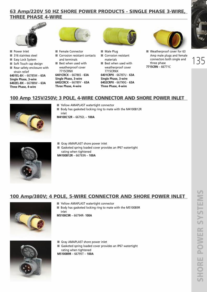
135
SHORE POWER SYSTEM
S
63 Amp/220V 50 HZ SHORE POWER PRODUCTS - SINGLE PHASE 3-WIRE,THREE PHASE 4-WIRE
� Power Inlet� 316 stainless steel� Easy Lock System� Soft Touch cap design� Rear safety enclosure withstrain relief
6401EL-BX – 66785M – 63ASingle Phase, 3-wire6402EL-BX – 66788W – 63AThree Phase, 4-wire
� Female Connector� Corrosion resistant contactsand terminals
� Best when used withweatherproof cover7715CRNX
6401CRCX – 66786S - 63ASingle Phase, 3-wire6402CRCX – 66789Y - 63A Three Phase, 4-wire
� Male Plug� Corrosion resistantmaterials
� Best when used withweatherproof cover7715CRNX
6401CRPX - 66787U - 63ASingle Phase, 3-wire6402CRPX - 66790G - 63AThree Phase, 4-wire
� Weatherproof cover for 63Amp male plugs and femaleconnectors both single andthree phase
7715CRN – 66771C
100 Amp 125V/250V; 3 POLE, 4-WIRE CONNECTOR AND SHORE POWER INLET
� Gray AMAPLAST shore power inlet� Gasketed spring loaded cover provides an IP67 watertightrating when tightened
M4100B12R – 66793N – 100A
� Yellow AMAPLAST watertight connector� Body has gasketed locking ring to mate with the M4100B12Rinlet
M4100C12R – 66792L – 100A
100 Amp/380V; 4 POLE, 5-WIRE CONNECTOR AND SHORE POWER INLET
� Gray AMAPLAST shore power inlet� Gasketed spring loaded cover provides an IP67 watertightrating when tightened
M5100B9R – 66795T – 100A
� Yellow AMAPLAST watertight connector� Body has gasketed locking ring to mate with the M5100B9Rinlet
M5100C9R – 66794R- 100A
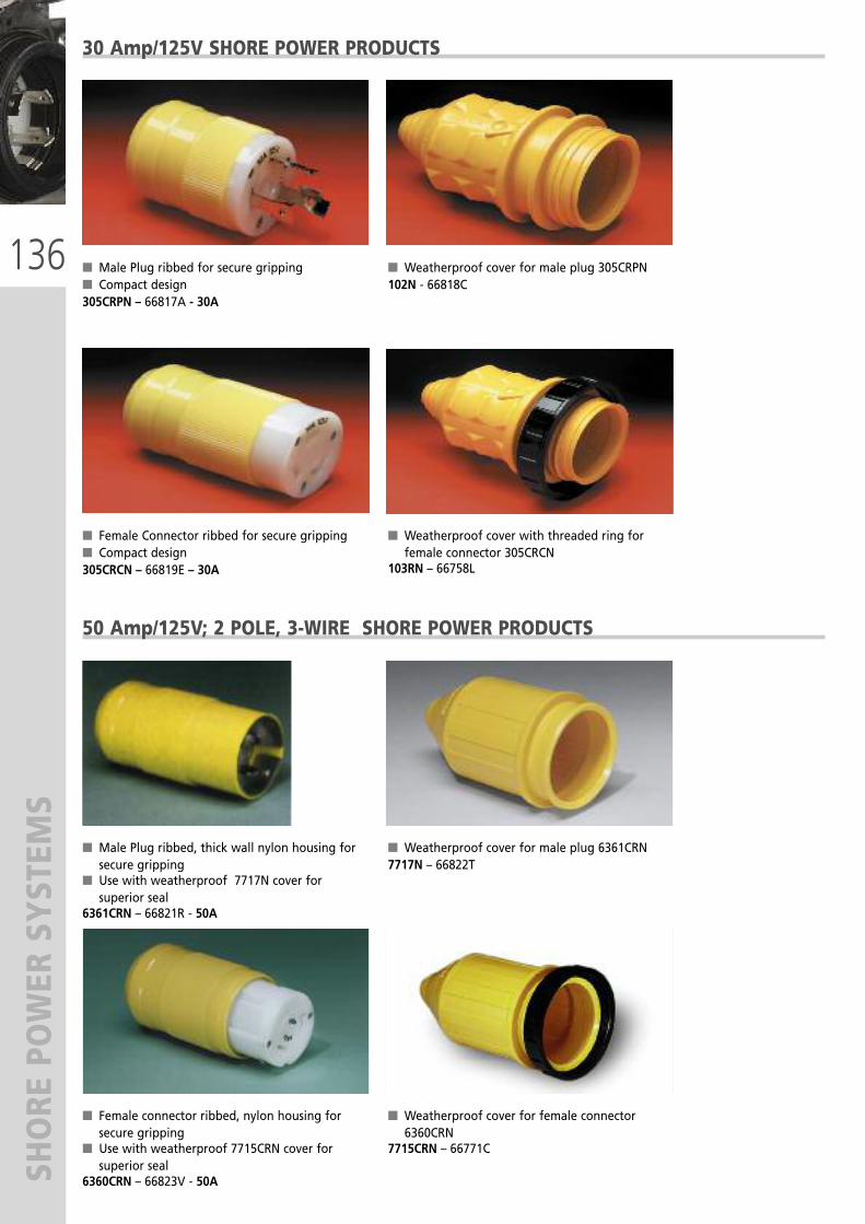
136
SHORE POWER SYSTEM
S
� Male Plug ribbed for secure gripping � Compact design305CRPN – 66817A - 30A
� Weatherproof cover for male plug 305CRPN102N - 66818C
� Female Connector ribbed for secure gripping � Compact design305CRCN – 66819E – 30A
� Weatherproof cover with threaded ring forfemale connector 305CRCN
103RN – 66758L
30 Amp/125V SHORE POWER PRODUCTS
� Male Plug ribbed, thick wall nylon housing forsecure gripping
� Use with weatherproof 7717N cover forsuperior seal
6361CRN – 66821R - 50A
� Weatherproof cover for male plug 6361CRN7717N – 66822T
� Female connector ribbed, nylon housing forsecure gripping
� Use with weatherproof 7715CRN cover forsuperior seal
6360CRN – 66823V - 50A
� Weatherproof cover for female connector6360CRN
7715CRN – 66771C
50 Amp/125V; 2 POLE, 3-WIRE SHORE POWER PRODUCTS

137
PERM
ANEN
T IMMERSION SHORE POWER CORD
S
PERMANENT IMMERSION SHORE POWER CORDS
MODEL PART No. DESCRIPTION APPLICABLE PLUG + SOCKET KIT
SPC32 67024T Shore power cord 3x2,5 mm2 – 1 metre 16
SPC34 67025V Shore power cord 3x4 mm2 – 1 metre 32
SPC36 67026X Shore power cord 3x6 mm2 – 1 metre 32
SPC310 67027Z Shore power cord 3x10 mm2 – 1 metre 50
SPC316 67028B Shore power cord 3x16 mm2 – 1 metre 63
SPC325 67029D Shore power cord 3x25 mm2 – 1 metre 100
SPC425 67030M Shore power cord 4x25 mm2 – 1 metre 100
SPC32/50 67031P Shore power cord 3x2,5 mm2 – 50 m spool -
SPC34/50 67032S Shore power cord 3x4 mm2 – 50 m spool -
SPC36/50 67033U Shore power cord 3x6 mm2 – 50 m spool -
SPC36/30 SPC34/50
FEATURES:
� Conductor: Red Copper Class 5 inconformity with HD 383 / IEC 228 rules
� Insulation: special compound� Protective covering: yellow specialcompound, for marine applications. Flameretardant: NFC.32-070 C2 – IEC 60332-1
� Rated voltage: 0,6/1kW – 50/60 Hz� Operating temperature in air: -40°C to+70°C. In motion: -25°C to +70°C
� Operating temperature in immersion: 50°C� Immersion depth: 250 m (820’) – 25 bar� Permanent immersion in conformity withBS 6920 – AD8 NF C 15-100 rule
� Flame retardant in conformity with NF C32-070 C2 – IEC 60332-1 rules
� Excellent resistance to weathering and lowwater absorption: 1% / 2%
� Excellent resistance to UV according toSEPAP test 1000 hours at 60°C
� Resistance to radiations: 80 Mrad (8.100cJ/kg)
� Excellent resistance to ozone in conformitywith VDE 0472 § 805 rule
� Resistance to salt fogs: in conformity withASTM B - 117 test 500 hours

138
SHORE POWER SYSTEM
S
� 316 stainless steel inlet � Locking waterproof cap� Soft Touch cap design� Watertight rear boot(PH/TV inlet only)
PH6592TV-SS - 66796VPhone and Cable TV InletTV6592 - 66797XCable TV Inlet
� Contoured glass-filledpolyester inlet
� Watertight cap� Soft Touch cap design� Stainless steel trim on capPH6444TV – 66800GPhone and Cable TV InletTV6444 - 66801JCable TV Inlet
� Standard glass-filledpolyester inlet
� Watertight cap� Stainless steel trim on capPH6574TV – 66798ZPhone and Cable TV InletTV6574 - 66799BCable TV Inlet
� Female Phone ConnectorWith cover
PH6629 – 66848M
PHONE AND CABLE TV INLETS
SeaLink® 12 VOLT RECEPTACLE AND PLUG
PHONE AND CABLE TV CORDSETSTV Cable Cordset� Standard 75 Ohm, with quick,slip-on connections and heavyduty boots included on bothends
TV99-25 - 66805T - 7,62 m (25 ft)
Telephone Cordset� 3 conductor vinyl cord providesportable connection for RVs andpleasure boats
PH6599 – 66802L - 15,24 m (50 ft)
12V DC Receptacle� Watertight sealing cap� Easy to install with suppliedmounting plate for frontpanel installation, orlocking ring for rear accessinstallation
� Compatible with standard12V plugs
12VRC – 66414B
12V DC Receptacle white� Weather resistant plugcover
� Easy to install, withsupplied mounting platefor front panel installation,or locking ring for rearaccess installation
� Compatible with standard12V plugs
12VRCW – 66862F
12V BR Receptacle and12V BP Plug� Weather resistant plugcover
� Ergonomic contoured gripfor easy hook-up andground blade alignment
� Easy to install, withsupplied mounting platefor front panel installation,or locking ring for rearaccess installation
12VBR – 67220T12VBP – 67219J
2V DC Plug� Moisture proof sealing ring� LED power indicator light� Interchangeable 10A fuse� Internal strain relief andcord seal
� Compatible with standard12V receptacles
12VPG – 66415D
12V DC Extension Cord� Heavy duty 18 gauge wire,extends to over 1,8 m (6 ft)
� Watertight cap � Plug features a LEDindicator light, moistureproof sealing ring, strainrelief and built-in 10A fuse
� Works with any standard12V plug and receptacle
12VXT – 66810K
12V DC Dual Outlet Cord� Heavy duty 18 gauge wire,extends to over 0,3 m (1 ft)
� Watertight cap� Plug features a LEDindicator light, moistureproof sealing ring, strainrelief and built-in 10A fuse
� Works with any standard12V plug and receptacle
12VAD – 66811M
SeaLink® ACCESSORIES

139
ENERGY UNLIMITED
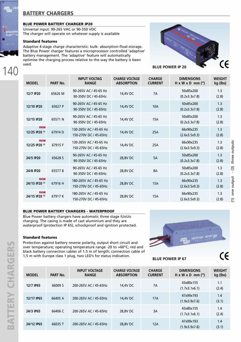
140
BATTERY CHARG
ERS
BLUE POWER BATTERY CHARGERS - WATERPROOFBlue Power battery chargers have automatic three stage IUoUocharging. The casing is made of cast aluminium and they arewaterproof (protection IP 65), schockproof and ignition protected.
Standard featuresProtection against battery reverse polarity, output short circuit andover temperature; operating temperature range -20 to +60°C; red andblack battery connection cables of 1.5 m of length; connection cable of1,5 m with Europe class 1 plug, two LED’s for status indication.
BLUE POWER IP 67
BLUE POWER BATTERY CHARGER IP20Universal input: 90-265 VAC or 90-350 VDCThe charger will operate on whatever supply is available
Standard features Adaptive 4-stage charge characteristic: bulk- absorption-float-storage.The Blue Power charger features a microprocessor controlled ‘adaptive’battery management. The ‘adaptive’ feature will automaticallyoptimise the charging process relative to the way the battery is beenused.
BATTERY CHARGERS
BLUE POWER IP 20
INPUT VOLTAG CHARGE VOLTAGE CHARGE DIMENSIONS WEIGHTMODEL PART No. RANGE ABSORPTION CURRENT H x W x D mm (“) kg (lbs)
90-265V AC / 45-65 Hz 50x85x200 1.312/7 IP20 65626 M
90-350V DC / 45-65Hz14,4V DC 7A
(0.2x3.3x7.8) (2.8)
90-265V AC / 45-65 Hz 50x85x200 1.312/10 IP20 65627 P
90-350V DC / 45-65Hz14,4V DC 10A
(0.2x3.3x7.8) (2.8)
90-265V AC / 45-65 Hz 50x85x200 1.312/15 IP20 65571 N
90-350V DC / 45-65Hz14,4V DC 15A
(0.2x3.3x7.8) (2.8)
130-265V AC / 45-65 Hz 66x90x235 1.312/25 IP20 (1) 67914 D
150-270V DC / 45-65Hz14,4V DC 25A
(2.6x3.5x9.3) (2.8)
130-265V AC / 45-65 Hz 66x90x235 1.312/25 IP20 (3) 67915 F
150-270V DC / 45-65Hz14,4V DC 25A
(2.6x3.5x9.3) (2.8)
90-265V AC / 45-65 Hz 50x85x200 1.324/5 IP20 65628 S
90-350V DC / 45-65Hz28,8V DC 5A
(0.2x3.3x7.8) (2.8)
90-265V AC / 45-65 Hz 50x85x200 1.324/8 IP20 65577 B
90-350V DC / 45-65Hz28,8V DC 8A
(0.2x3.3x7.8) (2.8)
180-265V AC / 45-65 Hz 66x90x235 1.324/15 IP20 (1) 67916 H
150-270V DC / 45-65Hz28,8V DC 15A
(2.6x3.5x9.3) (2.8)
180-265V AC / 45-65 Hz 66x90x235 1.324/15 IP20 (3) 67917 K
150-270V DC / 45-65Hz28,8V DC 15A
(2.6x3.5x9.3) (2.8)
INPUT VOLTAGE CHARGE VOLTAGE CHARGE DIMENSIONS WEIGHTMODEL PART No. RANGE ABSORPTION CURRENT H x W x D mm (“) kg (lbs)
43x80x155 1.112/7 IP65 66009 S 200-265V AC / 45-65Hz 14,4V DC 7A
(1.7x3.1x6.1) (2.4)
47x99x193 1.412/17 IP65 66405 A 200-265V AC / 45-65Hz 14,4V DC 17A
(1.9x3.9x7.6) (3.1)
43x80x155 1.424/3 IP65 66406 C 200-265V AC / 45-65Hz 28,8V DC 3A
(1.7x3.1x6.1) (2.4)
47x99x193 1.424/12 IP65 66035 T 200-265V AC / 45-65Hz 28,8V DC 12A
(1.9x3.9x7.6) (3.1)
newnew
newnew
newnew
newnew
(1) one output - (3) three outputs

141
BATTERY CHARG
ERS
BATTERY CHARGERS
CENTAUR BATTERY CHARGERS - ANALOGIC CONTROLCentaur battery chargers have automatic three stage IUoUo charging.All models are designed to operate all over the world without anyadjustment needed on input voltage range or frequency.
They have three isolated outputs to simultaneously charge 3 batterybanks. Each output is capable to supply the full rated current.
Standard featuresAluminium epoxy powder coated case with drip shield, circuit boardprotection with an acrylic coating, built-in temperature sensors, forcedcooling, protection against output short circuit and over temperature,analog ammeter, DIP switch for selection of charge/float voltage forflooded lead-acid, gel or AGM batteries, Europe CE certification andU.S.A. UL certification.Temperature range: -20 + 60° C CENTAUR
(1) 100 % output up to 40°C, 80% nominal output at 50°C and 60% of nominal at 60°C.
INPUT VOLTAGE CHARGE VOLTAGE CHARGE Ah DIMENSIONS WEIGHTMODEL PART No. RANGE ABSORPTION CURRENT(1) BATTERIES H x W x D mm (“) kg (lbs)
355x215x110 3.812/20 64886 K 90-265V AC / 45-65 Hz 14.3V DC 20 A 80 /200
(14.0x8.5x4.3) (8.4)
355x215x110 3.812/30 64887 M 90-265V AC / 45-65 Hz 14.3V DC 30 A 120/300
(14.0x8.5x4.3) (8.4)
426x239x135 5 12/40 64888 P 90-265V AC / 45-65 Hz 14.3V DC 40 A 160/400
(16.8x9.4x5.3) (11)
426x239x135 512/50 64889 S 90-265V AC / 45-65 Hz 14.3V DC 50 A 200/500
(16.8x9.4x5.3x) (11)
426x239x135 512/60 64890 A 90-265V AC / 45-65 Hz 14.3V DC 60 A 240/600
(16.8x9.4x5.3) (11)
505x255x130 1212/80 64891 C 90-265V AC / 45-65 Hz 14.3V DC 80 A 320/800
(19.9x10.0x5.2) (26.4)
505x255x130 1212/100 64892 E 90-265V AC / 45-65 Hz 14.3V DC 100 A 400/1000
(19.9x10.0x5.2) (26.4)
505x255x230 1612/200 64893 G 90-265V AC / 45-65 Hz 14.3V DC 200 A 800/2000
(19.9x10.0x9.1) (35.3)
355x215x110 3.824/16 64894 J 90-265V AC / 45-65 Hz 28.5V DC 16 A 45/150
(14.0x8.5x4.3) (8.4)
426x239x135 5 24/30 64895 L 90-265V AC / 45-65 Hz 28.5V DC 30 A 120/300
(16.8x9.4x5.3) (11)
505x255x130 1224/40 64896 N 90-265V AC / 45-65 Hz 28.5V DC 40 A 160/400
(19.9x10.0x5.2) (26.4)
505x255x130 1224/60 64897 R 90-265V AC / 45-65 Hz 28.5V DC 60 A 240/600
(19.9x10.0x5.2) (26.4)
505x255x230 1624/80 64898 T 90-265V AC / 45-65 Hz 28.5V DC 80 A 320/800
(19.9x10.0x9.1) (35.3)
505x255x230 1624/100 64899 V 90-265V AC / 45-65 Hz 28.5V DC 100 A 400/1000
(19.9x10.0x9.1) (35.3)

142
BATTERY CHARG
ERS
BATTERY CHARGERS
SKYLLA BATTERY CHARGERS - MICROPROCESSOR CONTROLSkylla battery chargers have automatic three stage IUoUo charging. They aredesigned for use on battery banks with 24Vcc / 48Vcc.They have two outputs, two full charge output and one oputput limited to 4 A
Standard featuresAluminium epoxy powder coated case with drip shield, circuit board protectionwith an acrylic coating, built-in temperature sensors, forced cooling, protectionagainst output short circuit and over temperature, battery temperature sensor,compensation on cable voltage fall, feeder function.
SKYLLA
PHOENIX BATTERY CHARGERS - MICROPROCESSOR CONTROLPhoenix automatic battery chargers with microprocessor can suitperfectly and automatically the charge for the batteries. During the 4charge stages (bulk-absorption-float-storage) the battery charger willmaintain the optimal charge depending on battery status and use.
Standard featuresAluminium epoxy powder coated case with drip shield, circuit boardprotection with an acrylic coating, built-in temperature sensors, forcedcooling, protection against output short circuit and over temperature,battery temperature sensor, compensation on cable voltage fall, twofull charge output and one oputput limited to 4 A, RS-485 data portfor computer connection, feeder function.
PHOENIX
(1) 100 % output up to 40°C, 80% nominal output at 50°C and 60% of nominal at 60°C.OPTIONAL: Skylla control panel (page 149)
INPUT VOLTAGE CHARGE CHARGE Ah DIMENSIONS WEIGHTMODEL PART No. RANGE VOLTAGE CURRENT(1) BATTERIES H x W x D mm (“) kg (lbs)
365x250x147 5.5TG 24/30 64904 J 185-265V AC / 45-65 Hz 28.5V DC 30 A + 4A 150/300 (14.4x9.9x5.8) (12.1)
TG 24/30 365x250x147 6GMDSS 66036 V 185-265V AC / 45-65 Hz 28.5V DC 30 A + 4A 150/300 (14.4x9.9x5.8) (13.2)
365x250x147 5.5TG 24/50 64905 L 185-265V AC / 45-65 Hz 28.5V DC 50 A + 4A 250/500 (14.4x9.9x5.8) (12.1)
TG 24/50 485x250x147 6GMDSS 67918 M 90-265V AC / 45-65 Hz 28.5V DC 50 A + 4A 250/500 (19.1x9.9x5.8) (13)
365x250x257 10TG 24/80 64906 N 185-265V AC / 45-65 Hz 28.5V DC 80 A + 4A 400/800 (14.4x9.9x10.1) (22)
365x250x257 10TG 24/100 64907 R 185-265V AC / 45-65 Hz 28.5V DC 100 A + 4A 500/1000 (14.4x9.9x10.1) (22)
TG 24/100 515x260x265 233 fasi 64908 T 320-450V AC / 45-65 Hz 28.5V DC 100 A + 4A 500/1000 (20.0x10.2x10.4) (48)
365x250x147 5.5TG 48/25 64909 V 185-265V AC / 45-65 Hz 57V DC 25 A + 4A 125/250 (14.4x9.9x5.8) (12.1)
365x250x257 10TG 48/50 64910 D 185-265V AC / 45-65 Hz 57V DC 50 A + 4A 250/500 (14.4x9.9x10.1) (22)
INPUT VOLTAGE CHARGE CHARGE Ah DIMENSIONS WEIGHTMODEL PART No. RANGE VOLTAGE CURRENT(1) BATTERIES H x L x P mm (“) kg (lbs)
(Absorption)
12/30 64900 A 90-265V AC / 45-65 Hz 14,4V DC 30 A (x2) + 4 A 100/400 350x200x108 (13.8x7.9x4.3) 3.8 (8.4)
12/50 64901 C 90-265V AC / 45-65 Hz 14,4V DC 50 A (x2) + 4 A 200/800 350x200x108 (13.8x7.9x4.3) 3.8 (8.4)
24/16 64902 E 90-265V AC / 45-65 Hz 28,8V DC 16 A (x2) + 4 A 100/200 350x200x108 (13.8x7.9x4.3) 3.8 (8.4)
24/25 64903 G 90-265V AC / 45-65 Hz 28,8V DC 25 A (x2) + 4 A 100/400 350x200x108 (13.8x7.9x4.3) 3.8 (8.4)
(1) 100 % output up to 40°C, 80% nominal output at 50°C and 60% of nominal at 60°C
(Absorption)

143
INVERTERS
INPUT VOLTAGE CONT. OUTPUT PEAK MAX EFFIC DIMENSIONS WEIGHT MODEL PART No. RANGE V DC POWER - VA(1) POWER - W % H x W x D mm (“) kg (lbs)
C12/1200 64918 W 9,5 – 17,0 1200 2400 93 375x214x110 (14.7x8.4x4.3) 10 (22)
C12/1600 64919 Y 9,5 – 17,0 1600 3000 93 375x214x110 (14.7x8.4x4.3) 10(22)
C12/2000 66407 E 9,5 – 17,0 2000 4000 93 520x255x125 (20.5x10.0x4.9) 13 (28.6)
12/3000 66037 X 9,5 – 17,0 3000 6000 93 362x258x218 (14.2x10.1x8.6) 18 (39.7)
C24/1200 64921 J 19,0 – 33,0 1200 2400 94 375x214x110 (14.7x8.4x4.3) 10 (22)
C24/1600 64922 L 19,0 – 33,0 1600 3000 94 375x214x110 (14.7x8.4x4.3) 10 (22)
C24/2000 66408 G 19,0 – 33,0 2000 4000 94 520x255x125 (20.5x10.0x4.9) 13 (28.6)
24/3000 64923 N 19,0 – 33,0 3000 6000 94 362x258x218 (14.2x10.1x8.6) 18 (39.7)
24/5000 66244 C 19,0 – 33,0 5000 10.000 94 444x328x240 (17.5x12.9x9.4) 28 (61.7)
PHOENIX INVERTERS
PHOENIX INVERTER UP TO 750 VA
Standard featuresAluminium epoxy powder coated case with drip shield, circuit boardprotection with an acrylic coating, forced cooling with temperature sensors,remote connector, battery cables (1.5 m), output short circuit protection,over temperature protection.
Developed for professional duty, Phoenix pure sine inverters are suitable for the widest range of applications. The design criteria have been to produce a true sine wave inverter with optimised efficiency without compromise inperformance. Employing hybrid HF technology, the result is a top quality product with compact dimensions, light inweight and capable of supplying power, problem-free, to any load. A unique feature of the SinusMax technology isvery high start-up power. Phoenix inverters, in fact, are well suited to power up difficult loads such as: refrigerationcompressors, electric motors and similar applications. Conventional high frequency technology does not offer suchextreme performance.
PHOENIX up to 750 VA
INPUT VOLTAGE CONT. OUTPUT PEAK MAX EFFIC. DIMENSIONS WEIGHT MODEL PART No. RANGE V DC POWER - VA(1) POWER - W % H x W x D mm (“) kg (lbs)
12/180 Schuko 64911 F 10,5 – 15,5 180 200 91 72x132x200 (2.8x5.2x7.9) 2.7 (5.9)12/350 Schuko 64912 H 10,5 – 15,5 350 500 90 72x155x237 (2.8x6.1x9.3) 3.5 (7.7)
12/750 Schuko 65400 J 10,5 – 15,5 750 1400 91 72x180x295 (2.8x7.1x11.6) 2.7 (5.9)
24/180 Schuko 64914 M 21,0 – 31,0 180 200 92 72x132x200 (2.8x5.2x7.9) 2.7 (5.9)
24/350 Schuko 64915 P 21,0 – 31,0 350 500 91 72x155x237 (2.8x6.1x9.3) 3.5 (7.7)
24/750 Schuko 65649A 21,0 – 31,0 750 1400 93 72x 180x295 (2.8x7.1x11.6) 2.7 (5.9)
(1) Continuous output power at 25°C
OUTPUT
: 230V AC ± 2%
- 50 Hz ± 2%
OUTPUT
: 230V AC ± 2% - 50 Hz ± 2%
PHOENIX INVERTER 1200 VA
Standard featuresAluminium epoxy powder coated case with drip shield, circuit boardprotection with an acrylic coating, forced cooling with temperaturesensors, protection against: output short circuit, overload, low batteryvoltage, reverse polarity, reverse voltage on output, input voltageripple, high temperature. Relay multifunction.
PHOENIX 1200 VA
(1) Continuous output power at 25°CAll models are suitable for parallel (max 6 parallel units) and 3-phase operationOPTIONAL: control panel Phonix CC Inverter (page 149)

144
INVERTER/BATTERY CHARG
ERS
DIMENSIONS WEIGHTMODEL PART No. H x W x D mm (“) kg (lbs)
EP C 12/1600/70-16 64948 F 510x214x110 (20x8.4x4.3) 11,7 (25,8)
MULTI-FUNCTION INVERTER/BATTERY CHARGERS
Power Assist – Boosting shore or generator powerWhere peak power is so often required only for a limited period, the Quattro makes sure that insufficient shore or generator power isimmediately compensated for by power from the battery. When the load reduces, the spare power is used to recharge the battery. With thisfeature, problems related to insufficient shore or generator power are solved once and for all. Air conditioning, an electric hob, a washingmachine, a dish washer, a 16A shore connection, or even less then16A, will not limit you in any way.
QUATTRO 5kVA
Two AC inputs with integrated transfer switchThe Quattro can be connected to two independent AC sources, for example shore-side powerand a generator, or two generators: the Quattro will automatically connect to the activesource.
Two AC outputsThe main output has no-break functionality. In the event of a grid failure, or shore orgenerator power being disconnected, the Quattro takes over the supply to the connectedloads. This happens so fast (less then 20 milliseconds) that computers and other electronicequipment will continue to operate without disruption. The second output is live only whenAC source is available. Loads that should discharge the battery, like a water heater for examplecan be connected to this output.
Virtually unlimited power thanks to parallel operationUp to 10 Quattro’s can operate in parallel. Ten units 24/5000/120, for example, will provide40kW / 50kVA output power and 1200 Amp charging capacity.
Three phase capabilityThree units can be configured for three-phase output and up to 6 sets of three units can beparallel connected to provide 75kW / 90kVA inverter power and more then 2000 Ampcharging capacity.
Power Control - Dealing with limited generator, shore-side or grid powerThe Quattro is a very powerful battery charger. It will therefore draw a lot of current from thegenerator or shore-side supply (16A per Quattro at 230 VAC). A current limit can be set forboth AC inputs. The Quattro will then take account of the other AC loads and use whatever isspare for charging, thus preventing the generator or shore supply from being overloaded.
EASYPLUSThe Poenix EasyPlus is a multifunctional energy system: 12 Volt 1600VA sine wave inverter(3000 Watt peak power) and 70A charger including 4A trickle charge for start battery.Unique PowerAssist© technology protects the shore or generator from being overloadedby adding extra inverter power when needed.4 stage adaptive charge technology for quick and accurate battery charging. RCD (30mA/16A) on AC output.Two Ac output sockets protected by 16A automatic circuit breakers for optimum safety.Second AC output active only when shore power is available.No-break system: uninterrupted switching between shore/generator and inverter.Battery cables and remote panel included.
QUATTRO5kVA
EASYPLUS
INPUT CONT. BATTERY CHARGE DIMENSIONS WEIGHT MODEL PART No. VOLTAGE OUTPUT INPUT VOLTAGE CHARGE H x W x D mm (“) kg (lbs)
RANGE POWER (1) RANGE CURRENT
14.4V DC (absorption) 362x258x218 19,012/3000/120-50-30 66880 M 9,5 - 17 3000
13.8V DC (float)120A + 4A
(14.3x10.1x8.6) (41.8)
14.4V DC (absorption) 470x350x280 34,012/5000/220-100-100 67437 V 19 - 33 5000
13.8V DC (float)220A + 4A
(18.5x13.8x11) (74.9)
28.8V DC (absorption) 362x258x218 19,024/3000/70-50-30 66881 K 19 - 33 3000
27.6V DC (float)70A + 4A
(14.3x10.1x8.6) (41.8)
28.8V DC (absorption) 444x328x240 30.024/5000/120-100-100 66097 S 19 - 33 5000
27.6V DC (float)120A + 4A
(17.4x12.9x9.4) (66.1)
57,6V DC (absorption) 470x350x280 45,024/8000/200-100-100 67388 T 19 - 33 8000
55,2V DC (float)110A + 4A
(18.5x13.8x11) (99.2)
(1) Continuous output power at 25°C
OUTPUT: 230V AC ± 2%

145
INVERTER/BATTERY CHARG
ERS
Power AssistIn the event that the onboard load exceeds the available shore power, the inverter function works in parallel with the shore connection toboost the total energy available and avoid overload. This works just the same with a generator.
Four stage adaptive charger and dual battery chargingThe main output provides a powerful charge to the battery system by means of advanced “adaptive charge” software. The softwareautomatically tunes three charging stages in order to give the battery what it needs and to add a forth stage for long periods of floatcharging. The second output is a float –only intended for engine start battery.
System configurationAfter installation, the MultiPlus is ready to work. If settings have to be changed, this can be done with the DIP switch setting procedure.Even parallel and 3-phase operation can be programmed with DIP switches. The VE.Net panel can be used as well for any settingmodification.
MULTIPLUSThe MultiPlus is a powerful true sine wave inverter, a sophisticated batterycharger that features adaptive charge technology, and a high-speed AC transferswitch in a single compact enclosure.The MultiPlus is compatible with Lithium-ion batteries.
Double AC outputsThe main output features a no-break function: when the shore power or thegenset power fails, the MultiPlus takes charge of the active loads withoutdiscontinuity. The second output is active only when an AC source is connected.The loads that may discharge the batteries, like the boiler, shall be connected tothe second output.
Parallel operation and three-phase configurationThe MultiPlus are able to be installed in parallel up to 6 units. In addition toparallel connection, three units of the same model can be configured for three-phase output: up to 6 sets of three units can be parallel connected for a totaloutput of 75KW /90kVA and a current of 2000A.
Power ControlThe MultiPlus is a very powerful battery charger, drawing high currents from thegenset or from the shore power (up to 10A per 5kVA Multi at 230 VAC). In orderto avoid any generator or shore overload, a current limit can be set through theMulti Control Panel; this way the Multiplus will charge the battery with thecurrent not used from the others AC loads on board.
MULTIPLUS
MULTI-FUNCTION INVERTER/BATTERY CHARGERS
(1) Continuous output power at 25°C
For a better use of all MultiPlus systems, it is necessary to install the Ve bus Multi Control 16 or the Digital Multi Controlremote control. It offers power control and power assist (page 149).
INPUT CONT. OUTPUT BATTERY CHARGE DIMENSIONS WHIGHTMODEL PART No. VOLTAGE POWER(1) OUTPUT INPUT CHARGE H x L x P mm (“) kg (lbs)
RANGE VA VOLTAGE RANGE CURRENT
C12/800/35-16 64927 X 9,5 – 16 800 35 A + 4A 375x214x110 (14.7x8.4x4.3) 10 (22)
C12/1200/50-16 64932 P 9,5 – 16 1200 50 A + 4A 375x214x110 (14.7x8.4x4.3) 10 (22)
C12/1600/70-16 64933 S 9,5 – 16 1600 70 A + 4A 375x214x110 (14.7x8.4x4.3) 10 (22)
C12/2000/80-30 64936 Y 9,5 – 16 2000 80 A + 4A 362x258x218 (14.2x10.1x8.6) 18 (39.7)
12/3000/120-16 64938 C 9,5 – 16 3000 120 A + 4A 362x258x218 (14.2x10.1x8.6) 18 (39.7)
12/3000/120-50 66875 R 9,5 – 16 3000 120 A + 4A 362x258x218 (14.2x10.1x8.6) 18 (39.7)
C24/800/16-16 64929 B 9,5 – 16 800 16 A + 4A 362x258x218 (14.2x10.1x8.6) 18 (39.7)
C24/1200/25-16 64940 N 19,5 – 33 1200 25 A + 4A 375x214x110 (14.7x8.4x4.3) 10 (22)
C24/1600/40-16 64941 R 19,5 – 33 1600 40 A + 4A 375x214x110 (14.7x8.4x4.3) 10 (22)
C24/2000/50-30 65725 P 19,5 – 33 2000 50 A + 4A 362x258x218 (14.2x10.1x8.6) 18 (39.7)
24/3000/70-16 64944 X 19,5 – 33 3000 70 A + 4A 362x258x218 (14.2x10.1x8.6) 18 (39.7)
24/3000/70-50 64945 Z 19,5 – 33 3000 70 A + 4A 362x258x218 (14.2x10.1x8.6) 18 (39.7)
24/5000/120-50 67433 L 19,5 – 33 5000 120 A + 4A 448x328x240 (17.6x12.8x9.4) 30 (66.1)
230V AC ± 2%
50 Hz ± 2%
187-265 V AC / 45-55 Hz

146
DC-DC CO
NVERTERS
ORION DC-DC CONVERTERS
Orion DC/DC Converters are designed to deliver a stable 12 Volt supply from a 24 Volt system. An inferior supply cancause irreparable damage to 12 Volt system, but the use of an Orion voltage converter prevents such problems. Next toconverters from 24V to 12V, a wide range of other models is available.
ORION DC-DC ISOLATED ORION DC-DC
NON ISOLATED ORION CONVERTERS
DIMENSIONS WEIGHTMODEL PART No. WATT H x W x D mm (“) kg (lbs)
2000 W 115/230 V 64969 P 2000 W 375x214x110 (14.8x8.4x4.3) 10 (22.0)
3600W 115/230 V 64970 Y 3600 W 362x258x218 (14.2x10.1x8.5) 23 (50.7)
7000W 230 V 64972 C 7000 W 362x258x218 (14.2x10.1x8.5) 24 (52.9)
INPUT VOLTAGE OUTPUT MAX OUTPUT TEMPERATURE DIMENSIONS WEIGHTMODEL PART No. RANGE - Vcc VOLTAGE - VDC CURRENT CONTROL H x W x D mm (“) kg (lbs)
Orion 24/12-5 64949 H 18-35 13,2 5.5 no 49x88x68 (1.9x3.5x2.7) 0.17 (0.37)
Orion 24/12-8 64950 S 18-35 13,2 8 no 49x88x98 (1.9x3.5x3.9) 0.25 (0.55)
Orion 24/12-12 64951 U 20-35 13,2 12 no 49x88x98 (1.9x3.5x3.9) 0.26 (0.57)
Orion 24/12-17 67919 P 18-35 12 17 no 49x90x95 (1.9x3.6x3.7) 0.29 (0.65)
Orion 24/12-20 64952 W 20-35 13,8 20 no 49x88x126 (1.9x3.5x5.0) 0.48 (1.1)
Orion 24/12-30 64953 Y 20-35 13,8 30 si 49x88x151 (1.9x3.5x5.9) 0.60 (1.3)
Orion 24/12-60 64954 A 20-35 13,8 60 si 88x100x180 (3.5x4.0x7.0) 1.20 (2.6)
Orion 12/24-7 64955 C 9-18 24 7 no 49x88x98 (1.9x3.5x3.9) 0.30 (0.7)
Orion 12/24-10 64956 E 9-18 24 10 no 49x88x126 (1.9x3.5x5.0) 0.40 (0.9)
To obtain 120A, it is possible to connect in parallel two 24/12-60 units.
ISOLATED (xx = input: 2,24 V DC - yy = output: 12 or 24 V DC
Orion xx/yy-100 - 12-24 12,5/24 100 W* no 49x88x152 (1.9x3.5x6.0) 0.50 (1.1)
Orion xx/yy-200 - 12-24 12,5/24 200 W* si 49x88x182 (1.9x3.5x7.2) 0.60 (1.3)
Orion xx/yy-360 - 12-24 12,5/24 360 W* si 64x163x160 (2.5x6.4x6.3) 1.40 (3.1)
Orion 12/27,6-12 67800 M 9-18 27,6 - si 64x163x160 (2.5x6.4x6.3) 1.40 (3.1)
* Nominal power
ISOLATED ORION CONVERTERS
ISOLATION TRANSFORMERSThe isolation transformer eliminates any electrical continuity between ACshore power and the ship. It is essential for safety and eliminates the needfor galvanic isolators and polarity alarms. The shore power is fed to theprimary side of the transformer and the ship is connected to thesecondary. The isolation transformer completely isolates the boat from theshore ground. By connecting all metal parts to the neutral output on thesecondary side of the transformer, a GFCI (ground fault currentinterrupter) will trip or a fuse will blow in case of a short circuit.
FeaturesAluminium epoxy powder coated case with drip shield, circuit boardprotection with an acrylic coating, toroidal transformer.
ISOLATION TRANSFORMER

147
ACCESSO
RIES
Battery isolators allow simultaneous charging of two or more batteries from onealternators, without connecting the batteries together. Discharging the accessorybattery, for example, will not result in discharging the starter battery.
ARGO – DIODE BATTERY ISOLATORSThe Argo battery isolators feature a low voltage drops thanks to the use ofSchottky diodes: at low current the voltage drop is approximately 0,3V and at therated output approximately 0,45V. All models are fitted with a compensation diode that can be used to slightlyincrease the output voltage of the alternator. This compensates for the voltagedrop over the diodes in the isolator.
ACCESSORIES
BATTERY ISOLATORS
BATTERY MONITORSThe BMV monitors feature an advanced microprocessor control system combined with highresolution measuring system for battery voltage and charge/discharge current. It can display:voltage, charge/discharge current, state of charge of the battery (in Ah or %), remainingcharge. Standard with connection cables and shunt.
Mounting hole: 52mm (2”)
BMV 600S - 66164 E - monitoring 1 battery 9-90 VDCBMV 602S - 66409 J - monitoring 2 batteries 9-90 VDCBMV 600H - 67434 N - monitoring 1 battery 70-350 VDCAvailable RS230 or NMEA2000 interface to connect to a computer
Alternator energize input Some alternators need DC voltage on the B+ output to start charging. Obviously, DC will be present when the alternatoris directly connected to a battery. Inserting a Diode or FET splitter will however prevent any return voltage/current from the batteries to the B+, and thealternator will not start. The new diode isolators have a special current limited energize input that will power the B+when the engine run/stop switch is closed.
ARGO FET BATTERY ISOLATORS: NO VOLTAGE LOSSDifferently from diode battery isolators, FET isolators have virtually no voltage loss.Voltage drop is less then 0,02 Volt at low current and averages 0,1 Volt at highercurrents.When using ARGO FET battery isolators, there is no need to also increase theoutput voltage of the alternator. Care should be taken however to keep cablelengths short and of sufficient cross section.
Alternator energize input The new ARGO FET isolators have a special current limited energize input that willpower the B+ when the engine run/stop switch is closed.
BMV 600S / BMV 600H
ARGO FET
MAX CHARGE ALTERNATOR No. of DIMENSIONS WEIGHTMODEL PART No. CURRENT MAX CURRENT BATTERIES H x L x P mm (“) kg (lbs)
802AC 67435 R 80A 80A 2 60x120x90 (2.4x4.7x3.5) 0.6 (1.3)
1003AC 64984 K 100A 100A 3 60x120x115 (2.4x4.7x4.5) 0.8 (1.8)
1202AC 64985 M 120A 120A 2 60x120x115 (2.4x4.7x4.5) 0.8 (1.8)
1403AC 64986 P 140A 140A 3 60x120x150 (2.4x4.7x6.0) 1.2 (2.6)
1602AC 64987 S 160A 160A 2 60x120x150 (2.4x4.7x6.0) 1.2 (2.6)
1603SC 64988 U 160A 160A 3 60x120x200 (2.4x4.7x7.9) 1.5 (3.3)
MAX CHARGE ALTERNATOR No. of DIMENSIONS WEIGHTMODEL PART No. CURRENT MAX CURRENT BATTERIES H x L x P mm (“) kg (lbs)
1002-FET 64989 W 100A 100A 2 65x120x200 (2.6x4.7x7.9) 1.2 (2.6)
1003-FET 64990 E 100A 100A 3 65x120x200 (2.6x4.7x7.9) 1.2 (2.6)
2002-FET 64991 G 200A 200A 2 65x120x200 (2.6x4.7x7.9) 1.2 (2.6)
2003-FET 64992 J 200A 200A 3 65x120x200 (2.6x4.7x7.9) 1.2 (2.6)
ARGO

148
ACCESSO
RIES BP-40i and BP-60i BP-200i
CONTINUOUS PEAK CONNECT DISCONNECT DIMENSIONS WEIGHTMODEL PART No. CURRENT CUR- VOLTAGE VOLTAGE H x W x D mm (“) kg (lbs)
A RENT V
13÷13.8V 11÷12.8V 46x46x80 0.11i 12/24-120 66245 E 120 180 e 26÷27.6V e 22÷25.7V (1.8x1.8x3.2) (0.24)
13÷13.8V 10,5÷12.8V 100x90x100 0.66i 12/24-225 67063 D 225 500 e 26÷27.6V e 21÷25.6V (4x3.5x4) (1.45)
13÷13.8V 10,5÷12.8V 78x102x110 0.9i 12/24-400 67064 F 400 2000 e 26÷27.6V e 21÷25.6V (3.0x4.0x4.3) (1.9)
CIRYX – MICROPROCESSOR CONTROLLED BATTERY COMBINER
BATTERY PROTECTION
No voltage lossCyrix battery separators are an excellent replacement for diode isolators. Themain feature is that there is virtually no voltage loss so that the output voltageof alternators or battery chargers does not need to be increased.
Prioritising the starter batteryIn a typical setup the alternator is directly connected to the starter battery. Theaccessory battery and possibly also a bow thruster and other batteries are eachconnected to the starter battery by Ciryx battery combiners.When a Ciryx senses that the starter battery has reached its connect voltagewill engage, to allow for parallel charging of the other batteries.
Bidirectional voltage sensingThe Ciryx senses the voltage of both connected batteries. It will therefore alsoengage if for example the accessory battery has been charged by a batterycharger.
Parallel connection in case of emergencyThe Cyrix can also be engaged with a switch to connect manually batteries inparallel. This is especially useful in case of emergency when the starter batteryis discharged or damaged.
12/24V auto ranging with Cyrix-iThe Cyrix-i 12/24-100 automatically detects system voltage.
The Cyrix battery combiner is a microprocessor controlled heavy duty relay that automatically connects batteries in parallel when one ofthem has reached a preset voltage (indicating that the battery has been charged) and disconnects when the voltage decreases below floatlevel (indicating that one or more batteries have been discharged).
The Victron battery protection disconnects thebattery from non essencial loads before it iscompletely discharged (which would damagethe battery) or before it has insufficientpower left to crank the engine.
MAX CONTINUOUS PEAK OPERATING LOAD DISCONNECT DIMENSIONS WEIGHTMODEL PART No. CURRENT CURRENT VOLTAGE RANGE DELAY H x W x D mm (“) kg (lbs)
80x60x40 0.2BP-40i 66038 Z 40A 120A 6-35V 1 minute (3.2x2.4x1.6) (0.5)
80x60x40 0.2BP-60i 65000 S 60A 120A 6-35V 1 minute (3.2x2.4x1.6) (0.5)
60x120x110 0.8BP-200i 66246 G 200A 480A 6-35V 1 minute (2.4x4.7x4.3) (1.8)
CYRIX

149
ACCESSO
RIES
REMOTE CONTROL PANELS AND CONNECTION CABLES
PHOENIX CCVE.Bus Multi ControlDMC - Digital Multi Control GX
MODEL PART No. DESCRIPTION
DMC 200/200 66717 W Digital Multi Control 200/200
DMC 200/200 GX 67920 Y Digital Multi Control 200/200GX
VE.Bus MC 16/200A 66247 J VE.Bus Multi Control 16/200A panel
Phoenix CC Inverter 65005 C Phoenix Inverter Control panel
Phoenix RC Inverter 66202 K Remote Control for 750VA Phoenix Inverter - 3m cable
Phoenix CC Charger 65006 E Phoenix Charger Control panel
Skylla CC 65007 G Skylla Control panell
CW 65008 J On-Off Skylla switch
BA 65009 L Battery alarm panel
CONTROL PANELS
MODEL CODICE DESCRIZIONE
UTP-5 RJ 45 65010 V UTP 5 m cable
UTP-10 RJ 45 65011 X UTP 10 m cable
UTP-15 RJ 45 65012 Z UTP 15 m cable
UTP-20 RJ 45 65013 B UTP 20 m cable
UTP-25 RJ 45 65014 D UTP 25 m cable
UTP-30 RJ 45 65015 F UTP 30 m cable
RS232/MK.2b 65018 M Connection Kit RS232/MK.2b
Victron Interface
USB/RS232 65019 P Converter USB/RS232
MK2/USB 67082 H Converter Kit USB/MK.2b
CABLES AND CONNECTION KIT
AUTOMATIC TRANSFER SWITCH66138 D Filax transfer switch CE 50Hz (up to 3500W) shore/inverter
STAINLESS STEEL MALE PLUG� 3 poles with cover IP67 rating
MP16-10 – 66730M – 16AMP32-10 – 66731P – 32A
� Waterproof IP67 shore power cable complete with plugand connector
� LED power indicator light� Protection cap on female connector� Stainless steel male plug� CE certified
SHORE CABLES WITH MOULDED PLUG AND CONNECTOR
MODEL
2821
2822
PART No.
66732 S
66738 E
DESCRIPTION
Shore Power Cord 3x2,5 - 15m (49.2’) 16A/250V
Shore Power Cord 3x2,5 - 25m (82.0’) 16A/250A
2836
2832
66733 U
66739 G
Shore Power Cord 3x4 - 15m (49.2’) 32A/250V
Shore Power Cord 3x4 - 25m (82.0’) 32A/250A
SHORE POWER CABLES WITHOUT TERMINALS
MODEL
70031/50
70032/50
PART No.
66824 X
66826 B
DESCRIPTION
Shore Power Cord 3 x 2,5 mm² - 50m spool
Shore Power Cord 3 x 4,0 mm² - 50m spool
70033/50 66827 D Shore Power Cord 3 x 6,0 mm² - 50m spool
16AMP/250V & 32AMP/250V - SHORE POWER CABLES
newnew

150
BATTERIES
BATTERIES
AGM
GEL
Deep cycle AGM batteries are more suitable for short-time delivery of very high currents (engine starting) than gelbatteries. Life: 7 – 10 years
*value for 20 hours of discharging
GEL deep cycle batteries. Life: 12 years
AGM Type PART No. CAPACITY* DIMENSIONS WEIGHTH x W x D mm (“) kg (lbs)
12/60 65022 C 60 - 55 Ah 299x138x227 (11.7x5.4x8.9) 20 (44.0)
12/66 65023 E 66 - 60 Ah 258x166x235 (10.1x6.5x9.2) 24 (52.9)
12/90 65024 G 90 - 80 Ah 350x167x183 (13.8x6.6x7.2) 27 (59.5)
12/110 65645 S 110 - 100 Ah 330x171x220 (13x6.7x8.7) 32 (70.5)
12/130 65025 J 130 - 120 Ah 410x176x227 (16.1x6.9x8.9) 38 (83.7)
12/165 65026 L 165 - 150 Ah 485x172x240 (19.1x6.7x9.4) 47 (103.6)
12/220 65027 N 220 - 200 Ah 522x238x240 (20.5x9.3x9.4) 65 (143.0)
GEL Type PART No. CAPACITY* DIMENSIONS WEIGHTH x W x D mm (“) kg (lbs)
12/60 65028 R 60 - 55 Ah 299x138x227 (11.7x5.4x8.9) 20 (44.0)
12/66 65029 T 66 - 60 Ah 258x166x235 (10.1x6.5x9.2) 24 (52.9)
12/80 65030 B 90 - 80 Ah 350x167x183 (13.8x6.6x7.2) 26 (57.3)
12/90 65646 U 110 - 100 Ah 330x171x220 (13x6.7x8.7) 33 (72.7)
12/110 65031 D 130 - 120 Ah 410x176x227 (16.1x6.9x8.9) 38 (83.7)
12/165 65032 F 165 - 150 Ah 485x172x240 (19.1x6.7x9.4) 48 (103.6)
12/220 65033 H 220 - 200 Ah 522x238x240 (20.5x9.3x9.4) 66 (143.0)
GEL 2 V DC Type PART No. CAPACITY* DIMENSIONS WEIGHTH x W x D mm (“) kg (lbs)
2/800 65034 K 800 Ah 215x193x710 (8.5x7.6x27.9) 68 (150)
2/1000 65035 M 1000 Ah 215x235x710 (8.5x9.2x27.9) 82 (181)
2/1500 65036 P 1500 Ah 215x277x855 (8.5x10.9x33.6) 120 (264)
2/2000 65037 S 2000 Ah 215x400x815 (8.5x15.7x32.1) 160 (352)
2/3000 65038 U 3000 Ah 215x580x815 (8.5x22.8x32.1) 240 (529)
*value for 20 hours of discharging
GEL long life 2Vcc batteries with lead calcium grids. Life: 20 years.
*value for 10 hours of discharging Lithium batteries available on request

151
MERMAID - MARINE AIR
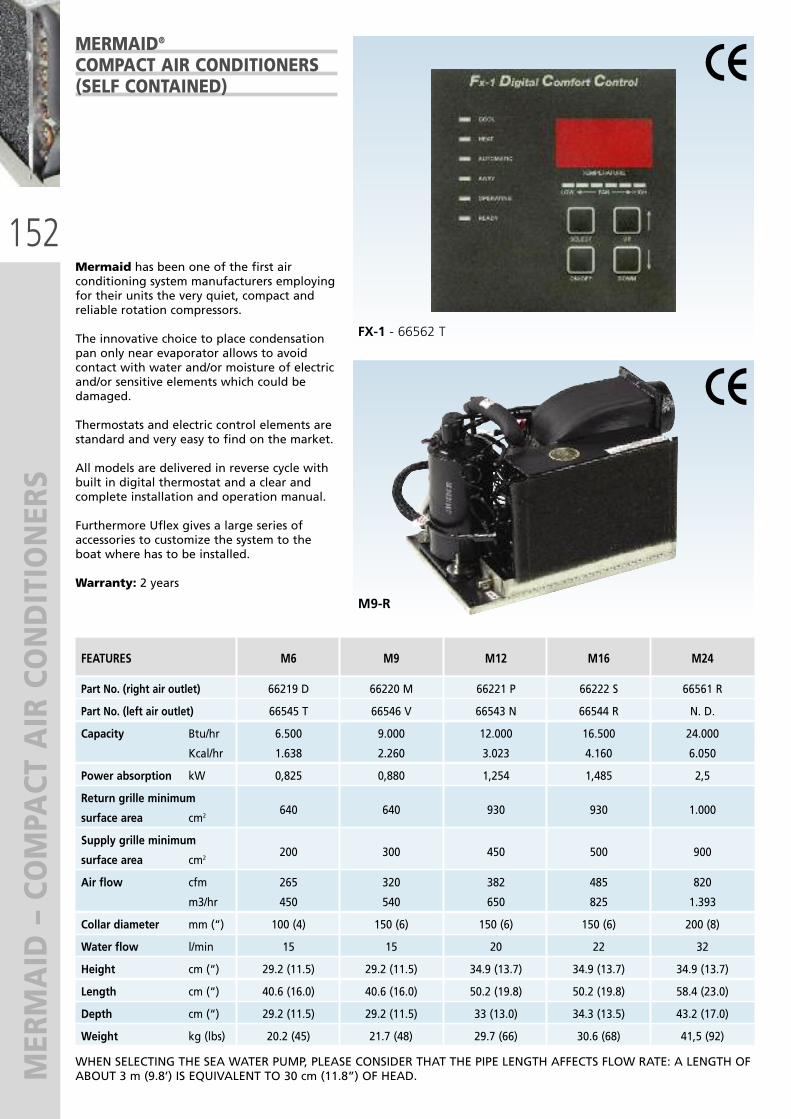
152
MERMAID – COMPACT AIR CONDITIONERS
Mermaid has been one of the first airconditioning system manufacturers employingfor their units the very quiet, compact andreliable rotation compressors.
The innovative choice to place condensationpan only near evaporator allows to avoidcontact with water and/or moisture of electricand/or sensitive elements which could bedamaged.
Thermostats and electric control elements arestandard and very easy to find on the market.
All models are delivered in reverse cycle withbuilt in digital thermostat and a clear andcomplete installation and operation manual.
Furthermore Uflex gives a large series ofaccessories to customize the system to theboat where has to be installed.
Warranty: 2 years
MERMAID®
COMPACT AIR CONDITIONERS(SELF CONTAINED)
FEATURES M6 M9 M12 M16 M24
Part No. (right air outlet) 66219 D 66220 M 66221 P 66222 S 66561 R
Part No. (left air outlet) 66545 T 66546 V 66543 N 66544 R N. D.
Capacity Btu/hr 6.500 9.000 12.000 16.500 24.000
Kcal/hr 1.638 2.260 3.023 4.160 6.050
Power absorption kW 0,825 0,880 1,254 1,485 2,5
Return grille minimum
surface area cm2640 640 930 930 1.000
Supply grille minimum
surface area cm2200 300 450 500 900
Air flow cfm 265 320 382 485 820
m3/hr 450 540 650 825 1.393
Collar diameter mm (“) 100 (4) 150 (6) 150 (6) 150 (6) 200 (8)
Water flow l/min 15 15 20 22 32
Height cm (“) 29.2 (11.5) 29.2 (11.5) 34.9 (13.7) 34.9 (13.7) 34.9 (13.7)
Length cm (“) 40.6 (16.0) 40.6 (16.0) 50.2 (19.8) 50.2 (19.8) 58.4 (23.0)
Depth cm (“) 29.2 (11.5) 29.2 (11.5) 33 (13.0) 34.3 (13.5) 43.2 (17.0)
Weight kg (lbs) 20.2 (45) 21.7 (48) 29.7 (66) 30.6 (68) 41,5 (92)
WHEN SELECTING THE SEA WATER PUMP, PLEASE CONSIDER THAT THE PIPE LENGTH AFFECTS FLOW RATE: A LENGTH OFABOUT 3 m (9.8’) IS EQUIVALENT TO 30 cm (11.8”) OF HEAD.
M9-R
FX-1 - 66562 T

153
MERMAID – COMPACT AIR CONDITIONERS
Smallest footprint on the market and weighs in at 31.5lbs. for the unit, and 4.7 lbs for electrical box. This unithas a rotatable blower and tapers down to a “V” shapefor those odd angle discharge installations. We use 4”ducting and recommend a minimum of 2,4” round supplygrills with this installation.
This unit will run off the new Honda eu1000i 1,000 wattportable generator, while in cool mode. Another option isto use a Victron 1,000 watt inverter and 400 Amp hours ofbattery power and you can anchor out (one average) forone night.
This unit is ideal for the “tight fit” installations and is awelcomed addition to larger vessels for individual climatecontrolled cabins. The Mermaid Model “M5” has a rotableblower so, no Air Discharge option is necessary.On average, this unit is designed to cool cruisers upto 26’ and sailboats up to 28’.All M5 models include a programmable digitalthermostat.Pump not included.
M5 - 66547 X
TECHNICAL FEATURES� Cool = 2.5 Amps � Add approximately one Amp for the standard seawaterpumps
� Start up amperage is calculated by running amperagemultiplied by 1.8
� Air conditioning for yachts 24’ up to 30’ � Cool only unit � Fx-1 Digital Thermostat included� Dimensions LxDxH: 29x38x29 cm (11.5”x15”x11.5”)� Weight: 16,4 kg (36.2 lbs)
M5 – 5.200 BTU CABIN AIRCONDITIONER
SEAWATER PUMPS
M5 - 66547 X
PMD-221 – 63426T � Seawater centrifugal Pump� Flow rate: 15 l/min (4.0 GPM)� Max Head: 2,6 m (8.5’)
PMD-371 – 63570A � Seawater centrifugal Pump� Flow rate: 25 l/min (5.5 GPM)� Max Head: 3,1 m (10.2’)
PMD-421 – 63344R � Seawater Centrifugal Pump� Flow rate: 35 l/min (9.2 GPM)� Max Head: 4,0 m (13.1’)
5513-1E01 – 63799K� Self priming seawater Pump� Flow rate: 5 - 20 l/min (1.3 – 9.0 GPM)� Self priming up to 3,0 m (9.8’)
ATTENTION Uflex recommends the use of a seawater in-line strainer to be installed between the seacock and the pump.Please contact our Technical Service to select the most suitable strainer to the application
62527U – In-line Strainer61124E – In-line Strainer63185X – In-line Strainer

154
AIR CONDITIONING SYSTEM
ACCESSO
RIES
AIR CONDITIONING SYSTEM ACCESSORIES
Uflex offers a large range of accessories forair conditioning systems, useful to properlyinstall both small and large systems. For theaccessory selection it is very important tofollow instructions given for each type ofequipment.
"T" & "Y" adaptersTo be directly connected on evaporatorscoupling flange; allow to divert air flow tofeed several de-livery frame. Available inmany inlet-outlet diameters.
"T" & "Y" divertersTo be connected pipe to pipe; allow to divertair flow to feed several delivery frames.Available in many inlet-outlet diameters.
Plenum jointAvailable both with preassembled fittings orcustom version to connect the system to theair ducts. It allows to best manage the air flowentering in the delivery frames.
Return frameAvailable with anodized aluminium finishingor in teak, are employed to ensure a suitableair flow to Fan Coil Split and Chiller and toCompact Air conditioning systems.
Delivery grilles and framesGrilles available with anodized aluminiumfinishing or in teak of several sizes; roundclosing frames black or white to be employedto deliver conditioned air into roomsenvironment.
Flexible insulated duct Available in different diameters, itsemployment is essential not only to improvesystem efficency but also to avoidcondensation sediment inside air ducts.
MERMAID - CONDENSATOR - 65138 YOn some boats, you can’t get a condensation drain line down to thebilge. Finally, you no longer have to put up with drainingcondensation water into the bilge or a shower sump. The Condensatoroperates on the venturi principal and “draws” the condensation waterfrom the tray and discards it with the unit’s cooling water. The kitincludes the condensator, a filter, hoses and mounting hardware.
MERMAID – BLEED OFF VALVE - 66548 ZThis is very simple bleed off valve, for installation just beyond the pump. Simply open the valve. Air escapes, and oncewater starts dripping through the bottom, close the valve and the water pump air lock is cleared.
CRD
PLENUM
DELIVERY GRILLE
CONTROL PANEL
CONNECTION CABLE
RETURN FRAME
CONNECTION BOX
MOUNTING HARDWARE
DRAIN
RAW WATER OUTLET
THRU-HULL
SEA WATERPUMP
STRAINER
VALVE
AIR DUCT
COMPACTUNIT
System diagram

155
MARINE GEN
ERATORS

156
MARINE GEN
ERATORS
WHISPER POWER – DIESEL MARINE GENERATORS
WhisperPower has a clear goal: to offer smart energy solutions based on the latest generator technology.By intelligently combining mechanics and electronics, WhisperPower provides sustainable, energy-saving and compactpower systems. Our power generators for mobile applications are used in professional, marine and recreational vehiclesworldwide. Whisper Power marine generators are compact, silent and reliable.Choose between marine diesel generators with a fixed rotational speed of 1500 or 3000 rpm at 3-25 kW.
GENERAL FEATURES
Continuous performanceSynchronous alternators generate the most ef-ficient initial surge tolerance and a pure sinewave for continuous AC output.
Efficient sound proofingCasing built with the best insulating materials,that allow a reduction of noise up to 52 dBa.
Vibration-freeSoft mounts between engine and sound shieldplus four external soft mounts ensure smoothrunning.
Cooling systemAlternator with water cooling via an integra-ted heat exchanger. The result is optimum co-oling and quietest operation.
Advanced control systemThe digital remote control panel allows auto-matic start/stop, monitors every most impor-tant functions and stores data.
Friendly maintenanceEfficient, lasting maintenance and service isassured thanks to easy access to all vital parts.
Easy installationPre-fab connections make installation easy(plug and play).
Installation kitOn request, installation kits are available forthe whole range of generators.
ConnectivityCAN Bus for local or remote connection.
M-SQ10
M-SC3.5

157
MARINE GEN
ERATORS - 3000 RPM
WHISPER GENERATORS - 3000 RPM SC SERIES
A 3000 RPM generator is ideally suited forsmall sailing and power yachts. The compactconstruction and the low weight allow insta-llation in small engine rooms.
The basic version is 3.5 kW and has a single cy-linder engine oil-cooled.
This model has high technology features suchas external connections, indirect cooling withheat exchanger, balanced shaft, anti-vibrationsystem and soundproof composite casing forextra lightness and easy removal.
The whole range includes 5, 6,5 and 9 kW ge-nerators with 2 or 3 cylinder engines, water-cooled. All generators are supplied with digi-tal remote control panel.
For powerful generators, a touch-screen 7”panel is available on request.
M-SC6
SC-3.5
DDC Panel

158
MARINE GEN
ERATOR – 3000 RPM
WHISPER 3000 RPM - TECHNICAL SPECIFICATIONS
** Peak power: 200%. Rating based on engine performance in conformity with ISO 3046; pressure 100 pKa, humidity 30%,temperature 25°C. Rating and tolerances of electric parameters are based on power factor 1.
PART No. 67340 D 67341 F 67409 P 67410 Y
GENERAL SPECIFICATIONS
Nominal power* 3 kW 5 kW 6,4 kW 9 kW
Nominal voltage 230V – 13A 230V – 22A 230V – 28A 230V – 39A
Output frequency 50 Hz 50 Hz 50 Hz 50 Hz
Power factor / cos phi 1 1 1 1
Voltage regulation Capacitor Capacitor Capacitor Capacitor
Voltage tolerance (V) ± 6% ± 5% ± 5% ± 5%
Frequency regulation Electronic Electronic Electronic Electronic
governor governor governor governor
Frequency tolerance (Hz) ± 5% ± 5% ± 1% ± 1%
Starter battery, AGM type, optional 12V – 55Ah 12V – 85Ah 12V – 85Ah 12V – 85Ah
Battery charge current Auxiliary Alternator Alternator Alternator
winding 4A 40A 40A 40A
Dimension with sound shield (lxlxh) 505x400x500 mm 690x525x520 mm 690x525x580 mm 804x525x680 mm
Dry weight 97 kg 178 kg 178 kg 210 kg
Ø Wet marine exhaust 40 mm 40 mm 40 mm 40 mm
Ø Dry exhaust pipe 1” BSP 1” BSP 1” BSP 1” BSP
Location oil refill cap top & side top & side top & side top & side
Max. operating angle 25° in all directions
Alternator water-cooled, no brushes, synchronous
Sound level at 7 m (dBA) 56.2 56.2 56.2 59.3
SPECIFICATIONS DIESEL ENGINE
Engine model OC60 L2E L2E L3E
Number of cylinders 1 2 2 3
Cylinder capacity 276 cc 635 cc 635 cc 952 cc
Bore & stroke 72 x 68 mm 2 x 76 x 70 mm 2 x 76 x 70 mm 3 x 76 x 70 mm
Air consumption 0,38 m3/min 0,95 m3/min 0,95 m3/min 1,43 m3/min
Engine cooling oil-cooled indirect watercooling watercooling watercooling
Fuel consumption (no load – full load) 0,7-1,2 l/hour 1-2,5 l/hour 1-3 l/hour 1-4 l/hour
Pump capacity 10-12 l/min 18 l/min 18 l/min 18 l/min
ACCESSORIES
Remote control panel Digital Diesel Control Digital Diesel Control Digital Diesel Control Digital Diesel Control
Additional remote control panel Optional Optional Optional Optional
7” touch screen No Optional Optional Optional
Power Take Off (PTO) No No No No
Three phase version No No No No
M-SC3.5 M-SC6 M-SC8 M-SC10

159
MARINE GEN
ERATOR – 1500 RPM
WHISPER GENERATORS - 1500 RPM SQ SERIES
A 1500 RPM marine generator allows a conti-nuous power output and a very quiet opera-tion.The SQ Series offers a range from 5.7kW to 25kW. The heat exchanger allows for optimum coo-ling of the engine, avoiding contact betweenthe engine and seawater. Maintenance is mi-nimized thanks to low RPM and attention todetail such as the cooling pump or the elec-tronic control unit. The soundproofing box allows full opening ofthe long side and a fast and easy access to thesensitive parts. DDC control panel is supplied as standard withall sets. Suitable to operate on powerful models, anhigh resolution full color touch screen (7”) isavailable.
M-SC6
M-SQ25
Touch screen
DDC Panel
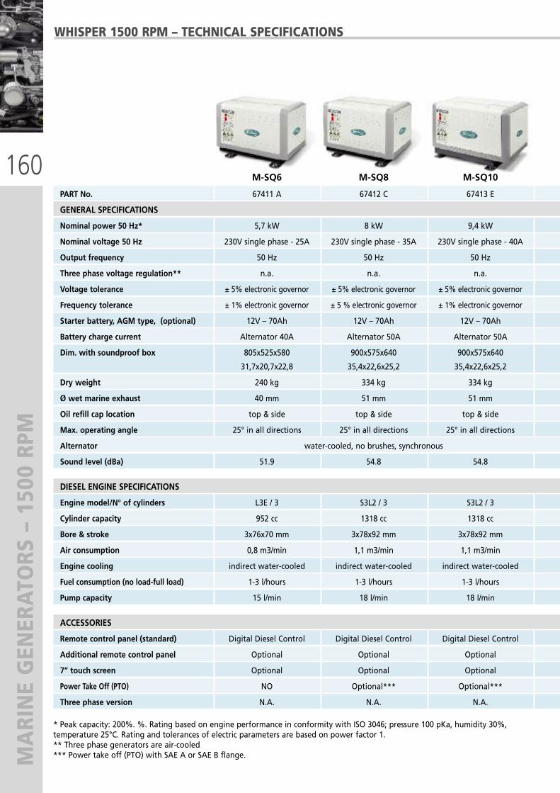
160
MARINE GEN
ERATORS – 1500 RPM
WHISPER 1500 RPM – TECHNICAL SPECIFICATIONS
* Peak capacity: 200%. %. Rating based on engine performance in conformity with ISO 3046; pressure 100 pKa, humidity 30%,temperature 25°C. Rating and tolerances of electric parameters are based on power factor 1.** Three phase generators are air-cooled*** Power take off (PTO) with SAE A or SAE B flange.
PART No. 67411 A 67412 C 67413 E 67342 H 67414 G 67415 J 67416 L
GENERAL SPECIFICATIONS
Nominal power 50 Hz* 5,7 kW 8 kW 9,4 kW 12 kW 16 kW 20 kW 25 kW
Nominal voltage 50 Hz 230V single phase - 25A 230V single phase - 35A 230V single phase - 40A 230V single phase - 52A 230V single phase - 70A 230V single phase - 86A 230V single phase - 108A
Output frequency 50 Hz 50 Hz 50 Hz 50 Hz 50 Hz 50 Hz 50 Hz
Three phase voltage regulation** n.a. n.a. n.a. AVR, ± 2% tolerance AVR, ± 2% tolerance AVR, ± 2% tolerance AVR, ± 2% tolerance
Voltage tolerance ± 5% electronic governor ± 5% electronic governor ± 5% electronic governor ± 5% electronic governor ± 5% electronic governor ± 2% electronic governor ± 2% electronic governor
Frequency tolerance ± 1% electronic governor ± 5 % electronic governor ± 1% electronic governor ± 1% electronic governor ± 3% electronic governor ± 3% electronic governor ± 3% electronic governor
Starter battery, AGM type, (optional) 12V – 70Ah 12V – 70Ah 12V – 70Ah 12V – 70Ah 12V – 120Ah 12V – 160Ah 12V – 160Ah
Battery charge current Alternator 40A Alternator 50A Alternator 50A Alternator 50A Alternator 50A Alternator 50A Alternator 50A
Dim. with soundproof box 805x525x580 900x575x640 900x575x640 1060x575x640 1060x575x640 1260x680x800 1260x680x800
31,7x20,7x22,8 35,4x22,6x25,2 35,4x22,6x25,2 41,7x22,6x25,2 41,7x22,6x25,2 49,6x26,8x31,5 49,6x26,8x31,5
Dry weight 240 kg 334 kg 334 kg 380 kg 454 kg 580 kg 580 kg
Ø wet marine exhaust 40 mm 51 mm 51 mm 51 mm 51 mm 63 mm 63 mm
Oil refill cap location top & side top & side top & side top & side top & side top & side top & side
Max. operating angle 25° in all directions 25° in all directions 25° in all directions 25° in all directions 25° in all directions 25° in all directions 25° in all directions
Alternator water-cooled, no brushes, synchronous water-cooled, no brushes, synchronous
Sound level (dBa) 51.9 54.8 54.8 55.7 56.1 58.3 58.3
DIESEL ENGINE SPECIFICATIONS
Engine model/N° of cylinders L3E / 3 S3L2 / 3 S3L2 / 3 S4L2 / 4 S4Q2 / 4 S4S / 4 S4S / 4
Cylinder capacity 952 cc 1318 cc 1318 cc 1758 cc 2505 cc 3331 cc 3331 cc
Bore & stroke 3x76x70 mm 3x78x92 mm 3x78x92 mm 4x78x92 mm 4x88x103 mm 4x94x120 mm 4x94x120 mm
Air consumption 0,8 m3/min 1,1 m3/min 1,1 m3/min 1,5 m3/min 2,1 m3/min 2,8 m3/min 2,8 m3/min
Engine cooling indirect water-cooled indirect water-cooled indirect water-cooled indirect water-cooled indirect water-cooled indirect water-cooled indirect water-cooled
Fuel consumption (no load-full load) 1-3 l/hours 1-3 l/hours 1-3 l/hours 1-4 l/hours 1-5 l/hours 1-6 l/hours 1-8 l/hours
Pump capacity 15 l/min 18 l/min 18 l/min 18 l/min 22 l/min 22 l/min 22 l/min
ACCESSORIES
Remote control panel (standard) Digital Diesel Control Digital Diesel Control Digital Diesel Control Digital Diesel Control Digital Diesel Control Digital Diesel Control Digital Diesel Control
Additional remote control panel Optional Optional Optional Optional Optional Optional Optional
7” touch screen Optional Optional Optional Optional Optional Optional Optional
Power Take Off (PTO) NO Optional*** Optional*** Optional*** Optional*** Optional*** Optional***
Three phase version N.A. N.A. N.A. Yes Yes Yes Yes
M-SQ6 M-SQ8 M-SQ10

161
MARINE GEN
ERATORS – 1500 RPM
WHISPER 1500 RPM – TECHNICAL SPECIFICATIONS
PART No. 67411 A 67412 C 67413 E 67342 H 67414 G 67415 J 67416 L
GENERAL SPECIFICATIONS
Nominal power 50 Hz* 5,7 kW 8 kW 9,4 kW 12 kW 16 kW 20 kW 25 kW
Nominal voltage 50 Hz 230V single phase - 25A 230V single phase - 35A 230V single phase - 40A 230V single phase - 52A 230V single phase - 70A 230V single phase - 86A 230V single phase - 108A
Output frequency 50 Hz 50 Hz 50 Hz 50 Hz 50 Hz 50 Hz 50 Hz
Three phase voltage regulation** n.a. n.a. n.a. AVR, ± 2% tolerance AVR, ± 2% tolerance AVR, ± 2% tolerance AVR, ± 2% tolerance
Voltage tolerance ± 5% electronic governor ± 5% electronic governor ± 5% electronic governor ± 5% electronic governor ± 5% electronic governor ± 2% electronic governor ± 2% electronic governor
Frequency tolerance ± 1% electronic governor ± 5 % electronic governor ± 1% electronic governor ± 1% electronic governor ± 3% electronic governor ± 3% electronic governor ± 3% electronic governor
Starter battery, AGM type, (optional) 12V – 70Ah 12V – 70Ah 12V – 70Ah 12V – 70Ah 12V – 120Ah 12V – 160Ah 12V – 160Ah
Battery charge current Alternator 40A Alternator 50A Alternator 50A Alternator 50A Alternator 50A Alternator 50A Alternator 50A
Dim. with soundproof box 805x525x580 900x575x640 900x575x640 1060x575x640 1060x575x640 1260x680x800 1260x680x800
31,7x20,7x22,8 35,4x22,6x25,2 35,4x22,6x25,2 41,7x22,6x25,2 41,7x22,6x25,2 49,6x26,8x31,5 49,6x26,8x31,5
Dry weight 240 kg 334 kg 334 kg 380 kg 454 kg 580 kg 580 kg
Ø wet marine exhaust 40 mm 51 mm 51 mm 51 mm 51 mm 63 mm 63 mm
Oil refill cap location top & side top & side top & side top & side top & side top & side top & side
Max. operating angle 25° in all directions 25° in all directions 25° in all directions 25° in all directions 25° in all directions 25° in all directions 25° in all directions
Alternator water-cooled, no brushes, synchronous water-cooled, no brushes, synchronous
Sound level (dBa) 51.9 54.8 54.8 55.7 56.1 58.3 58.3
DIESEL ENGINE SPECIFICATIONS
Engine model/N° of cylinders L3E / 3 S3L2 / 3 S3L2 / 3 S4L2 / 4 S4Q2 / 4 S4S / 4 S4S / 4
Cylinder capacity 952 cc 1318 cc 1318 cc 1758 cc 2505 cc 3331 cc 3331 cc
Bore & stroke 3x76x70 mm 3x78x92 mm 3x78x92 mm 4x78x92 mm 4x88x103 mm 4x94x120 mm 4x94x120 mm
Air consumption 0,8 m3/min 1,1 m3/min 1,1 m3/min 1,5 m3/min 2,1 m3/min 2,8 m3/min 2,8 m3/min
Engine cooling indirect water-cooled indirect water-cooled indirect water-cooled indirect water-cooled indirect water-cooled indirect water-cooled indirect water-cooled
Fuel consumption (no load-full load) 1-3 l/hours 1-3 l/hours 1-3 l/hours 1-4 l/hours 1-5 l/hours 1-6 l/hours 1-8 l/hours
Pump capacity 15 l/min 18 l/min 18 l/min 18 l/min 22 l/min 22 l/min 22 l/min
ACCESSORIES
Remote control panel (standard) Digital Diesel Control Digital Diesel Control Digital Diesel Control Digital Diesel Control Digital Diesel Control Digital Diesel Control Digital Diesel Control
Additional remote control panel Optional Optional Optional Optional Optional Optional Optional
7” touch screen Optional Optional Optional Optional Optional Optional Optional
Power Take Off (PTO) NO Optional*** Optional*** Optional*** Optional*** Optional*** Optional***
Three phase version N.A. N.A. N.A. Yes Yes Yes Yes
M-SQ12 M-SQ16 M-SQ20 M-SQ25

162
INSTALLATION KITS
INSTALLATION KITS
When you install a Whisper Power generator, all connections and fittings shall be of the highest quality. Whisper Powerprovides a range of kits to make installation faster and easier. There are the anti-vibration kit, complete with base plateand shock mounts; the anti-siphon kit that prevents water percolation into the engine when it stops; the fuel kit allowsto keep clean the fuel flowing into the generator; the water inlet kit avoids that seawater impurities goes into the ge-nerator; the exhaust and separator kits allow to have minimum noise and easy installation.Service kits are available too: the A kit for easier and more frequent maintenance and the B kit for larger maintenance.
WATER INLET KITS Water inlet kit consisting of:Water strainer, hoses, hose clamps, through-hull fitting and seacock
67417 N – Water inlet kit 12.5 mm (1/2”) for M-SC 3.5 – wet exhaust67418 R – Water inlet kit 20 mm (3/4”)67419 T – Water inlet kit 25 mm (1”)
SYPHON BREAKER KITSSyphon breaker kit consisting of:Siphon breaker, hoses and hose clamps
67420 B – Syphon breaker kit 12.5 mm (1/2”) for M-SC 3.5 – wet exhaust67421 D - Syphon breaker kit 20 mm (3/4”)67422 F - Syphon breaker kit 25 mm (1”)
DELTA EXHAUST KITSDELTA exhaust kit consisting of:Exhaust silencer/waterlock with rotating connections, through-hull fitting, hoses and hoseclamps67423 H – DELTA exhaust kit 40 mm (15/8”)67424 K - DELTA exhaust kit 51 mm (2”)67425 M - DELTA exhaust kit 63 mm (21/2”)
DELTA WATER/GAS SEPARATOR KITS DELTA water/gas separator consisting of:Water/gas separator with rotating connections, through-hull fitting, hoses, hose clamps andseacock67426 P – DELTA water/gas separator kit 40 mm (15/8”)67427 S - DELTA water/gas separator kit 51 mm (2”)67428 U - DELTA water/gas separator kit 63 mm (21/2”)
ANTI-VIBRATION KITSAnti-vibration kits consisting of:Schock mounts and installation material
67429 W – anti-vibration kit M-SC 3.567430 E – anti-vibration kit M-SC 6/867431 G – anti-vibration kit up to 280 kg
FUEL KITSFuel kit consisting of:Fuel filter, hose clamps and couplings
67432 J – Fuel kit for W-SC, W-SQ, M-SC and M-SQ
SERVICE KITS These kits are available for maintenance or to have essential parts at hands.The A-kit includes filters a V-beltsThe B-kit includes seals and various mechanical parts.Specify type of generator when ordering.

126
176
464
60
480
628
513
521
504
60
176
464
60
480
628
513
521
504
60
163
GEN
VERTER PO
WER SYSTEM
S
GENVERTER – VARIABLE SPEED DIESEL GENERATORS
GV-4� Advanced way of power generation� Variable speed � Permanent magnet fly wheel integratedalternator
� Liquid cooled� High efficient & fuel saving� Ultra compact & light weight� 3.8 kW output power, 230 VAC – 50 Hz
GV 7i� 3.8 k*230V diesel generator� 3.5 kW/230V sine wave inverter� Built-in charger for 12, 24 or 48V DCbatteries
� Variable speed 2500 - 3400 rpm� Fully automatic operation� Silent, liquid cooled diesel engine� Plug & play installation
PART No. GV-4 - 67707 Y GV 7i - 67709 C (24VDC)
GENERAL SPECIFICATIONS
Variable speed 2500-3400 2500-3400
Combined system output 3.8 kW 7 kW
Generator power (running engine) 3.8 kW 3.8 kW
Silent power (inverter mode) - 3.5 kW
Peak output AC 36A 12t 36A 12t
Nominal voltage AC 230 VAC 230 VAC
Nominal current AC 16.5 A 30.0 A
Nominal frequency AC 50.0 Hz 50.0 Hz
Thd nominal operation AC < 5% < 5%
Leading or lagging power factor 1 0,1 – 1
Parallel use (multiple systems) 2 units max not feasible
Parallel use with AC grid (<25A) - silent
mode only
Capacity (starter) battery (AGM) 12V 55Ah 12V 55Ah
Starter battery charge current 10A 10A
BATTERY CHARGER SPECIFICATIONS
Charge current - 0 - 90 A
Charge from Ac grid - 190 – 260 VAC
Temperature sensor - Sì
INVERTER SPECIFICATIONS
Silent power 5 sec. - 9.0 kW
Silent power - 3.5/3.0 kW
Standby consumption - 225 W
Efficiency - Max 94%
MECHANICAL SPECIFICATIONS
Cooling Indirect watercooling
Dry / Wet exhaust pipe 92 kg 92 kg
Ø wet exhaust 1” BSP 1 5/8” BSP
Location oil refill cap - top&side
Max. Operation angle 20° 25°
Alternator sheet metal
Temperature range operational -20°C a 40°C -20°C a 40°C
Protection degree engine compartment IP44/electronic compartment IP23
Remote control Pannel DDC Touch 3.5
SPECIFICATIONS DIESEL ENGINE
Engine model WHISPER WP1 WHISPER WP1-4
Number of cylinders 1 1
Cylinder capacity 300 cc 300 cc
Air consumption 0.42m3/min @3000 rpm
Engine cooling fully oil cooled fully oil cooled
Fuel consumption 0.8-1.5 l/h 0.8-1.5 l/h
GV-4 GV 7i
new new
PANEL FOR GV-7I
DDC PANEL FOR GV-4
GENEVERTERW/M-GV7i
GV 7i - 67708 A (12VDC)

164
BELT POWER AND PORTABLE DIESEL GEN
ERATOR
BELT POWER – BELT DRIVEN 3.5 – 5.0 KW 230VAC/50HZ GENERATOR
W-TG 3000 – PORTABLE DIESEL GENERATOR
PART No. W-BD 3.5 - 67923 E W-BD 5 - 67924 G
GENERAL SPECIFICATIONS
Power (continuous) 3500 W 5000 W
Max current (continuous) 16A 27A
Max. inrusch current (320 ms) 32A 40A
Voltage 230V 230V
Frequency 50 Hz 50 Hz
INVERTER BOX
Dimensions (h*w*d) 376x323x127 mm (14.8”x12.7”x5”)
Net weight 9.6 kg (21.16 lb) 9.6 kg (21.16 lb)
Efficiency 95% 95%
GENERATOR
Net weight 6.9 kg (15.2 lb) 6.9 kg (15.2 lb)
Dimensions (h*w*d) 159x178x190 mm (6.3”x7”x7.5”)
Voltage 200-340 V trifase
Field voltage 14.4V 14.4V
REMOTE CONTROL PANEL
Dimensions (h*w*d) 116x79x19 mm (4.6”x3.1”x0.7”)
PART No. 67925 J
GENERAL SPECIFICATIONS
Continuous power 2.8 kW
Nominal voltage 230 VAC
Nominal frequency 50 Hz
Max. current 13A
Nominal speed 3000 rpm
Voltage regulation AVR
DC output 12V / 8.3A
ENGINE SPECIFICATIONS
Engine 1 cylinder, 4 stroke,
air cooled, direct
injection, diesel engine
Continuous power 5Hp
Bore & stroke 78 x 64 mm
Displacement 306 cc
Cooling system forced air cooling
Lube oil capacity 1,1 l
Starting system starter motor
Voltage regulation AVR
Fuel tank capacity 12,5 l
Alarms low oil pressure
Dimensions (l*w*h) 720x480x630 mm (28.3”x18.9”x24.8”)
Dry weight 106 kg (233.7 lb)
The Whisper Power W-BD alternator is designed for installation in the boat engine compartment and is driven by a belt of one of theengine pulley. Often, an additional pulley has to be installed. The alternator output is connected to an inverter, which converts theincoming current into a stable sine wave 230V/50Hz. Mounting brackets to mount the generator on the engine are available.
SAFETY ALARMSShort circuit, overload, over temperature, low/high rpm, low/high voltage.
The W-TG 3000 generator is fully self contained (fuel tank, starter battery, exhaust) and readyfor operation. For power up to 2.8 kW the air cooled W-TG 3000 is a low cost solution.
STANDARD FEATURES� Meets 2000/14/CE rule� Automatic air bleeding mechanism� AC voltmeter� AC circuit breakers� Additional DC output and DC over currentprotection
� Extra large fuel tank with fuel gauge� Exhaust silencer and starter battery
new new
WhisperPower BV
480
720
710
630
480
720
710
630
630
480
720
710
630
630
new new
165
SILENCING AND EXHAUST SYSTEM
S

166
SILENCING AND EXHAUST SYSTEM
S
A marine engine exhaust system ejects the cooling water as well assilencing the engine’s combustion noise and removing the exhaustgasses. The system must create minimal restriction to the flow ofexhaust gasses, known as back pressure, or the engine may bedamaged.
Halyard® produces GRP silencers using specialist resins, allowingHalyard® silencers to survive remarkably high temperatures if thecooling water supply blocks for short periods. Halyard® silencers areusually made from filament wound GRP tube, manufactured in ourown plant, which is hand-laminated with flat sheet bases. Every singlesilencer produced is pressure tested individually to guard against leaks. GRP is used as the base material to avoid the corrosion and acousticproblems of welded stainless units, and to avoid the low meltingpoints of plastic silencers. Although normal marine exhausts run atbetween 40°C and 60°C, Halyard® silencers will remain operationalafter exposure to 300°C or more, while a plastic unit will melt ataround 150°C. Halyard® GRP silencers are approved by Lloyds Register.
Here are four main objectives achieved by Halayard®:
1. To reduce noise by between 40% and 90%.
2. To cool the exhaust, and eject the engine cooling water through theexhaust without excessive back pressure.
3. To minimise the risk of water running back up the exhaust and intothe engine cylinders, causing serious engine damage.
4. To site the outlets at the stern of the boat to minimise exhaustfumes on board.
In-line Silencers
Water Separators and Silencers
Dual Chamber Silencers
HALYARD® SILENCING AND EXHAUST SYSTEMS – LLOYDS APPROVED

167
SILENCING AND EXHAUST SYSTEM
S
HALYARD® - SILENCING AND EXHAUST SYSTEMSAPPLICATIONS AND INSTALLATION DIAGRAMS
ENGINE WELL ABOVE WATERLINEThis engine is sited well above the waterline, and the exhaust systemhas a downhill gradient of 1 in 8, or steeper, as it scope to the stern.The water will naturally run down the slope and away from theengine. A standard in-line silencer will achieve a noise reduction ofapproximately 40%. A dual chamber silencer will achieve up to 80%.(Sketch A)
ENGINE JUST ABOVE WATERLINEWater could run back into the engine if the vessel pitches on itsmooring – or a wave could do the same. There are two solutions:
1. Fit a "high riser". This is an extension to the exhaust outlet on theengine taking it well above water-line to create a 1 in 8 gradientfrom the water injection on the engine down to the stern. An in-line silencer can then be used with a noise reduction of around40%. Alternatively you might get the necessary height by using aDual Chamber silencer, with a noise reduction of around 80%.(Sketch B)
2. Fit a dual chamber silencer.The dual chamber silencer means the hose scope steeply down fromengine to silencer, and again from silencer to stern. The geometryneeds careful checking, but it can solve the problem and it offers anoise reduction up to 80%. (Sketch C)
ENGINE NEAR OR BELOW WATERLINEMost displacement craft have their engines low down. The sketchshows a typical water-trap silencer positioned below and behind theengine. The hose from this silencer runs gradually down to the stern.Water in the system drains into the silencer when the engine isstopped. A wave coming up the stern is unlikely to climb over thegooseneck. (Sketch D)
Siphon breakers should always be used in the cooling water supply toinstallations of this type. Normal lift silencers reduce noise by 45% orso. You can add a water separator to increase this around 90%.
Sketch A
Sketch B
Sketch C
Sketch D
WHERE’S THE WATERLINE?Marine exhausts are cooled by sea water, so it’s essential that the water cannot run back up the exhaust and into theengine’s cylinders. The resulting damage can be catastrophic. A few simple rules need to be followed, and engineinstallers should seek expert advice if in any doubt.
NOTE: Dimensions on Lift Silencing systems vary widely, but a 12m yacht normally needs a drop of 300mm (12") from the waterinjection point on the engine exhaust outlet to the top of the lift silencer. The gooseneck should then be 450mm (18") above waterline– or more if the exhaust is to one side. The lift silencer should not fill with water by more than 30% when the engine is stopped, and itmust be large enough for this. These are very general guidelines and will change with angles of heel, size of vessel, engine choice etc.Individual installations must be checked with qualified designers or marine engineers.

168
SILENCING AND EXHAUST SYSTEM
SHALYARD® LIFT SILENCERS - LLOYDS APPROVEDUP TO 50% NOISE REDUCTION
Halyard® Lift silencers are designed for use with engines positioned on,or below waterline. Halyard® Lift Silencers are as popular with generators as they are withpropulsion engines.
SIDE IN, TOP OUT LIFT SILENCERSThe side in, top out lift silencer is the best selling small lift silencer inthe Halyard® range. Every unit is pressure tested and gel-coated for a durable and smartappearance. Available lengths: page 171
TOP IN, TOP OUT LIFT SILENCERSIn many applications a top inlet unit will be easier to use. The noiseresult and cost are the same as the side inlet units, and the samerigorous quality tests apply.Available lengths: page 171
HORIZONTAL LIFT SILENCERSThese low lying units can be very useful in sailing yachts, where thesilencer needs to be secured alongside the propeller shaft. Themoulded ends are used on smaller units.Available lengths: page 172
HALYARD® IN-LINE SILENCERS - LLOYDS APPROVEDUP TO 50% NOISE REDUCTION
Halyard® in-line silencers are used where the engine is well above thewater-line, or where a high-riser has been fitted to achieve a 1 in 8gradient from the engine to the transom outlet. They are simple tospecify and fit, and ideally need to be 0,5m to 1m behind the engine.The internal design requires the exhaust gasses and water to bubblethrough a layer of water on the bottom of the silencer to reducenoise. They offer excellent noise reduction and are widely used onboth pleasure and commercial engines.
ROUND IN-LINE SILENCERSThese silencers are made from enormously strong filament woundtube, giving the maximum possible protection if the exhaust back-fires.Every unit is pressure tested before being gel-coated. They must beinstalled within 5 degrees of horizontal.Available lengths: page 172
OVAL IN-LINE SILENCERSOur oval silencers are hand-moulded for use where the round bodyunit cannot be accommodated. They give the same excellent resultsand every single unit is pressure tested and gel-coated. The inlets canbe angled to ease the connection to the engine and positioned on theend or the side.Available lengths: page 172

169
SILENCING AND EXHAUST SYSTEM
S
HALYARD® DUAL CHAMBER SILENCERS - LLOYDS APPROVEDUP TO 80% NOISE REDUCTION
HALYARD® EXHAUST WATER SEPARATORS - LLOYDS APPROVEDNOISE REDUCTION UP TO 90%
Halyard® Dual Chamber silencers is the best wet-exhaust silencer on themarket today.
Exhaust noise reductions of up to 80% can be achieved and the backpressure created by the unit is minimal.
Most units are hand-built with inlet and outlet positioned to suit theparticular craft.
The quality standards applied are designed to give a life in excess often years on a privately owned craft.Available lengths: see page 172
Fitting a water separator into the exhaust toreplace the gooseneck removes water once ithas done its cooling job, draining this quietlyaway below waterline. Back pressure isreduced dramatically. The separator removesthe principal cause of back pressure and stopsthe sploshing noise which accompanies everymarine engine ticking over in a harbour – oron a generator sploshing away in a quiethaven somewhere, to the fury of nearbyboats.
EXHAUST WATER SEPARATORS MS SERIESThe MS Series of exhaust water separatorscovers a wide range of exhaust diameters, forgenerators and propulsion engines withcooling water flow rates of up to 40 liters perminute. The MS unit will remove all but a tinytrickle of water.
Halyard developed the concept of water separation and now designs and produces systems for engines ranging fromsmall diesel generators through to mighty power providers on super-yachts and commercial craft.
HALYARD® CAN SUPPLY ON REQUEST EXHAUST SEPARATORS COMPLETE WITH STANDARD HOSES (UP TO 160°C) ORSILICON HOSES (UP TO 270°C), AND COMPLETE WITH SILICON FITTINGS AND BRONZE SIPHON BREAK.For any further information, please contact our Technical Service.
A mm
269
B mm
90
C mm
269
D mm
73
E mm
100
F mm
38
G mm
38
PART No.
66902 R
HALYARD PART. N°
H011214
MS 4000 SERIES

170
SILENCING AND EXHAUST SYSTEM
S
MS5020MS5030
MS7505 MS7510
A B
CD
A B
CD
E
MS5025
MS5010 MS5005MS5015E
MS5020MS5030
MS7505 MS7510
A B
CD
A B
CD
E
MS5025
MS5010 MS5005MS5015E
MS5020MS5030
MS7505 MS7510
A B
CD
A B
CD
E
MS5025
MS5010 MS5005MS5015E
MS5020MS5030
MS7505 MS7510
A B
CD
A B
CD
E
MS5025
MS5010 MS5005MS5015E
HALYARD® SILENCERS AND EXHAUST WATER SEPARATORS – LLOYDS APPROVED
MS 5000 SERIES
� Three sizes cover exhaust diameters of 45 mm, 50 mm, 60 mm (1 3/4", 2”, 2 ½")� Maximum water flow rate: 45 litres per minute
MID-GEN EXHAUST WATER SEPARATORS
MS 7500 SERIES
� Size covers exhaust diameter: 75 mm (3”)� Maximum water flow rate: 65 litres per minute
PART No.
66883 P
HALYARDPART NO.
H07889
Amm
371
66884 S H08363
straight outlet
90 deg. outlet 371
Bmm
100
143
Cmm
371
371
Dmm
100
100
Emm
180
180
PART No.
H010257
HALYARDPART NO.
MS5005
H010258 MS5010
H010261 MS5015
Amm
306
306
306
Bmm
89
89
89
Cmm
306
306
306
Dmm
133
83
164
Emm
125
125
125
Fmm
50
50
63
Gmm
45
50
60
H010259 MS5020 306 112 306 133 125 50 45
H010260 MS5025 306 112 306 83 125 50 50
H010262 MS5030 306 112 306 164 125 63 60
PART No.
65843 W
HALYARDPART NO.
HFS025
A1mm (“)
60 - (2.5)
Emm (“)
38 - (1.5)
Bmm
140
Cmm
100
Dmm
356
Gmm
100
65845 A HFS035 89 - (3.5) 51 - (2.0)140 110 406 100
65568 A HFS040 102 - (4.0) 51 - (2.0)170 110 398 100
Fmm
144
144
144
Hmm
70
70
85
PART No.
65846 C
HALYARDPART NO.
HWS035
A1mm
90
65847 E HWS040 102
65848 G HWS050 127
A2mm
90
102
127
Bmm
38
38
51
Cmm
250
260
310
Dmm
356
356
406
Emm
356
356
406
Fmm
120
120
150
Gmm
110
110
112
65849 J HWS060 152 152 51 335 406 406 158 100
MID-ENGINE EXHAUST WATER SEPARATORS
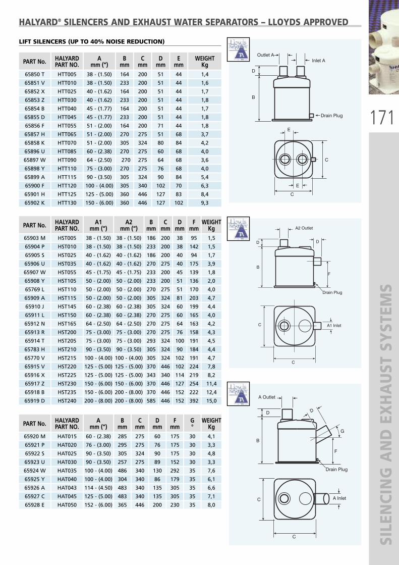
171
SILENCING AND EXHAUST SYSTEM
S
HALYARD® SILENCERS AND EXHAUST WATER SEPARATORS – LLOYDS APPROVED
LIFT SILENCERS (UP TO 40% NOISE REDUCTION)
PART No.
65850 T
65851 V
HALYARDPART NO.HTT005
HTT010
Amm (“)38 - (1.50)
38 - (1.50)
Bmm164
233
Cmm200
200
Dmm51
51
Emm44
44
WEIGHTKg1,4
PART No.
65903 M
HALYARDPART NO.HST005
A1mm (“)38 - (1.50)
A2mm (“)38 - (1.50)
Bmm186
Cmm200
Dmm38
Fmm95
WEIGHTKg1,5
65904 P HST010 38 - (1.50) 38 - (1.50) 233 200 38 142 1,5
65905 S HST025 40 - (1.62) 40 - (1.62) 186 200 40 94 1,7
65906 U HST035 40 - (1.62) 40 - (1.62) 270 275 40 175 3,9
65907 W HST055 45 - (1.75) 45 - (1.75) 233 200 45 139 1,8
65908 Y HST105 50 - (2.00) 50 - (2.00) 233 200 51 136 2,0
65769 L HST110 50 - (2.00) 50 - (2.00) 270 275 51 170 4,0
65909 A HST115 50 - (2.00) 50 - (2.00) 305 324 81 203 4,7
65910 J HST145 60 - (2.38) 60 - (2.38) 305 324 60 199 4,4
65911 L HST150 60 - (2.38) 60 - (2.38) 270 275 60 165 4,0
65912 N HST165 64 - (2.50) 64 - (2.50) 270 275 64 163 4,2
65913 R HST200 75 - (3.00) 75 - (3.00) 270 275 76 158 4,3
65914 T HST205 75 - (3.00) 75 - (3.00) 293 324 100 191 4,5
65770 V HST215 100 - (4.00) 100 - (4.00) 305 324 102 191 4,7
65783 H HST210 90 - (3.50) 90 - (3.50) 305 324 90 184 4,4
65916 X HST225 125 - (5.00) 125 - (5.00) 343 340 114 219 8,2
65915 V HST220 125 - (5.00) 125 - (5.00) 370 446 102 224 7,8
65918 B HST235 150 - (6.00) 200 - (8.00) 370 446 152 222 12,4
65917 Z HST230 150 - (6.00) 150 - (6.00) 370 446 127 254 11,4
65919 D HST240 200 - (8.00) 200 - (8.00) 585 446 152 392 15,0
PART No.
65920 M
HALYARDPART NO.HAT015
Amm (“)60 - (2.38)
Bmm285
Cmm275
Dmm60
Fmm175
WEIGHTKg4,1
65921 P HAT020 76 - (3.00) 295 275 76 175 3,3
G°30
30
65922 S HAT025 90 - (3.50) 305 324 90 175 4,8
65923 U HAT030 90 - (3.50) 257 275 89 152 3,3
30
30
65924 W HAT035 100 - (4.00) 486 340 130 292 7,6
65925 Y HAT040 100 - (4.00) 304 340 86 179 6,1
35
35
65926 A HAT043 114 - (4.50) 483 340 135 305 6,6
65927 C HAT045 125 - (5.00) 483 340 135 305 7,1
35
65928 E HAT050 152 - (6.00) 365 446 200 230 8,035
35
1,6
65852 X
65853 Z
HTT025
HTT030
40 - (1.62)
40 - (1.62)
164
233
200
200
51
51
44
44
1,7
1,8
65854 B
65855 D
HTT040
HTT045
45 - (1.77)
45 - (1.77)
164
233
200
200
51
51
44
44
1,7
1,8
65856 F
65857 H
HTT055
HTT065
51 - (2.00)
51 - (2.00)
164
270
200
275
71
51
44
68
1,8
3,7
65858 K
65896 U
HTT070
HTT085
51 - (2.00)
60 - (2.38)
305
270
324
275
80
60
84
68
4,2
4,0
65897 W
65898 Y
HTT090
HTT110
64 - (2.50)
75 - (3.00)
270
270
275
275
64
76
68
68
3,6
4,0
65899 A
65900 F
HTT115
HTT120
90 - (3.50)
100 - (4.00)
305
305
324
340
90
102
84
70
5,4
6,3
65901 H
65902 K
HTT125
HTT130
125 - (5.00)
150 - (6.00)
360
360
446
446
127
127
83
102
8,4
9,3

172
SILENCING AND EXHAUST SYSTEM
SHALYARD® SILENCERS AND EXHAUST WATER SEPARATORS – LLOYDS APPROVED
LIFT SILENCERS (up to 40% noise reduction)
IN-LINE SILENCERS (up to 40% noise reduction)
PART No.
65943 A
HALYARDPART NO.HILR003
A1mm (“)60 - (2.38)
A2mm (“)60 - (2.38)
Bmm152
Cmm343
Dmm70
Gmm40
WEIGHTKg2,2
65944 C HILR005 75 - (3.00) 75 - (3.00) 203 485 75 59 2,9
65945 E HILR010 90 - (3.50) 90 - (3.50) 207 590 100 53 3,3
65946 G HILR015 100 - (4.00) 100 - (4.00) 254 645 100 68 5,8
65947 J HILR020 115 - (4.50) 115 - (4.50) 254 730 115 61 6,3
65948 L HILR025 125 - (5.00) 125 - (5.00) 254 800 127 55 7,7
65949 N HILR030 125 - (5.00) 150 - (6.00) 305 1016 127 65 9,4
65950 X HILR035 150 - (6.00) 150 - (6.00) 305 965 152 65 10,4
65951 Z HILR040 150 - (6.00) 200 - (8.00) 398 1280 200 94 16,0
65952 B HILR045 200 - (8.00) 200 - (8.00) 398 1282 203 94 *
65954 F HILR050 250 - (10.00) 250 - (10.00) 446 1600 254 87 *
65955 H HILR055 300 - (12.00) 300 - (12.00) 459 1918 305 116 *
PART No.
65956 K
HALYARDPART NO.HIL0005
A1mm (“)
125 - (5.00)
A2mm (“)
125 - (5.00)
Cmm800
WEIGHTKg10,8
65957 M HIL0006 125 - (5.00) 150 - (6.00) 940 10,6
65958 P HIL0010 150 - (6.00) 150 - (6.00) 940 9,5
Dmm140
152
152
Emm229
225
225
Fmm385
385
385
Gmm118
105
105
65959 S HIL0012 150 - (6.00) 200 - (8.00) 1334 12,0203 270 420 93
65960 A HIL0015 200 - (8.00) 200 - (8.00) 1282 16,0203 270 420 93
65961 C HIL0016 200 - (8.00) 250 - (10.00) 1164 21,5203 295 465 87
65962 E HIL0020 250 - (10.00) 250 - (10.00) 1600 *254 365 630 164
PART No.
65964 J
HALYARDPART NO.HDC025
A1mm (“)
100 - (4.00)
A2mm (“)
100 - (4.00)
Bmm600
65965 L HDC035 125 - (5.00) 125 - (5.00) 700
65966 N HDC040 125 - (5.00) 150 - (6.00) 800
Cmm420
420
420
65967 R HDC045 150 - (6.00) 150 - (6.00) 800 420
65968 T HDC050 150 - (6.00) 200 - (8.00) 800 420
65969 V HDC055 200 - (8.00) 200 - (8.00) 900 525
65970 D HDC060 200 - (8.00) 250 - (10.00) 900 628
65971 F HDC065 250 - (10.00) 250 - (10.00) 1000 628
65972 H HDC070 300 - (12.00) 300 - (12.00) 1000 672
PART No.
65929 G
65930 R
HALYARDPART NO.HEE005
HEE010
Amm (“)38 - (1.50)
40 - (1.62)
Bmm270
270
Cmm186
186
Dmm51
51
Fmm137
137
WEIGHTKg1,5
1,8
65931 T
65932 V
HEE020
HEE035
45 - (1.77)
50 - (2.00)
270
355
186
186
51
51
137
137
1,8
2,2
65933 X
65934 Z
HEE040
HEE045
50 - (2.00)
50 - (2.00)
440
270
254
186
51
51
200
137
4,4
2,1
65935 B
65936 D
HEE060
HEE065
60 - (2.38)
60 - (2.38)
330
450
262
262
51
51
200
200
3,8
4,4
65937 F
65938 H
HEE070
HEE080
64 - (2.50)
75 - (3.00)
440
440
262
262
51
76
200
200
4,3
4,5
65939 K
65940 U
HEE090
HEE095
90 - (3.50)
100 - (4.00)
465
462
254
305
89
102
184
192
4,0
5,5
65942 Y
65941 W
HEE105
HEE100
125 - (5.00)
114 - (4.50)
599
462
305
305
111
114
241
192
9,9
6,2
*Weight on request.
DUAL CHAMBER SILENCERS (up to 70% noise reduction)

173
NOISE INSULATION MATERIALS
NOISE INSULATION MATERIALS
HALYARD® QUALITYMarine diesels create very high noise levels – often well over 100 decibels.Engines are always located close to the boat user, generally in engine spacesmade from GRP, timber, or steel. Noise insulation changes all this. It adds a softfacing to hard bulkheads to absorb noise and stop it bouncing around andgrowing. It features a clever multi-layer construction to make a thin materialmore effective than simple insulations many times thicker.
� The absorption layerA thick layer of fire zero rated foam which soaks up noise and stops itbouncing around the engine space.
� The transmission layerA high density barrier provides the highest possible mass and gives the bestnoise reduction. The damping layer weighs 5kgs per square meter – more thanthe lead sheet used in older materials.
� The isolation layerThis thin layer of foam has a crucial function: It acts like the gap in doubleglazing and stops the noise which hits the transmission layer being carriedthrough to the bulkhead – just like the gap in double glazing.
The multi-layer construction used in Halyard® materials offers the best possibleacoustic result in a thicknesses which can be accommodated in the tightestengine space, beating simpler materials many times as thick.
PROTECTIVE SKIN� MaritexAn immensely tough fibreglass cloth with a sealed metallised skin so it cannotabsorb oil. It won’t tear or fray. It looks heavy duty, and it is fire zero rated.Maritex is simply the best facing in the Halyard® range.Maritex is fire zero rated to BS 476 parts 6 and 7.
� SealglassA tough off-white glass cloth, sealed against oil. The cloth is extremely toughand will not tear. The sealant will burn off in a fire. The material meets the ISO9094 fire requirements of the EU Recreational Craft Directive.
� Re-inforced Silver PolyesterThis facing meets the requirements of the Recreational Craft Directive. Itprovides a seal to keep oil out. You can pierce it, but it has a reinforcing layerbehind it. It will burn, but once laminated in place it meets the ISO 9094 firerequirements of the EU Recreational Craft Directive. In a fire the facing willburn, but not the foam behind it.
HOW TO CHOOSE THE PROPER THICKNESS� 45mm (1.75").This unique double damper material was invented by Halyard® and is designedto give the best possible result for the minimum thickness and weight. It isused where big turbo-charged engines are involved, or for vessels where noiseis a particular problem
Supplied with 2 sheets 1000 mm x 600 mm (39” x 24”) per box
� 2mm (1.25"). The standard thickness used throughout the industry. Today’s fire zero ratedfoams have increased the weight and made this material even more effective.32 mm is the choice for any installation where the builder wants an excellentresult at a sensible cost. Remember, you can always double layer it in criticalareas.
Supplied with 4 sheets 1000 mm x 600 mm (39” x 24”) per box
� 12mm (0.5"). The budget material when thickness or cost are crucial. Although it is only12mm or half an inch thick, this material is highly effective and will reducenoise by 50% if used properly. You can also double layer it in places.
Supplied with 4 sheets 1000 mm x 600 mm (39” x 24”) per box
Sealglass
Re-inforced Silver Polyester

174
NOISE INSULATION MATERIALS
15
10
5125 250 500 1000 2000 4000
Frequency Hz
3/4 Ply + 45mm Halyard Material
3/4 Ply Only
45
40
35
30
25
20
15
10
5125 250 500 1000 2000 4000
Noi
se L
oss
dB
Frequency Hz
3/4 Pl + 12mm Halyard Material
3/4 Ply Only
45
40
35
30
25
20
15
10
5125 250 500 1000 2000 4000
Noi
se L
oss
dB
Frequency Hz
3/4 Ply + 32mm Halyard Material
3/4 Ply Only
45
40
35
30
25
20Noi
se L
oss
dB
15
10
5125 250 500 1000 2000 4000
Frequency Hz
3/4 Ply + 45mm Halyard Material
3/4 Ply Only
45
40
35
30
25
20
15
10
5125 250 500 1000 2000 4000
Noi
se L
oss
dB
Frequency Hz
3/4 Pl + 12mm Halyard Material
3/4 Ply Only
45
40
35
30
25
20
15
10
5125 250 500 1000 2000 4000
Noi
se L
oss
dB
Frequency Hz
3/4 Ply + 32mm Halyard Material
3/4 Ply Only
45
40
35
30
25
20Noi
se L
oss
dB
NOISE INSULATION MATERIALS
12 mm (1/2") Materials - All are supplied with 4 sheets 1000 x 600mm (39" x 24") per box: tot 2,4 m2
66383 T S3002 Maritex faced material
66384 V S3004 Sealglass faced material
66385 X S3003 Reinforced silver polyester faced material
12 mm (1/2") Self-adhesive materials - All are supplied with 4 sheets 1000 x 600mm (39" x 24") per box: tot 2,4 m2
66386 Z S5002 Maritex faced material
66387 B S5004 Sealglass faced material
66388 D S5003 Reinforced silver polyester faced material
32mm (1.25") Materials - All are supplied with 4 sheets 1000mm x 600mm (39" x 24") per box: tot 2,4 m2
66007 M S3017 Maritex faced material
66389 F S3015 Sealglass faced material
66390 P S3016 Reinforced silver polyester faced material
32mm (1.25") Self-adhesive materials - All are supplied with 4 sheets 1000mm x 600mm (39" x 24") per box: tot 2,4 m2
66391 S S5017 Maritex faced material
66392 U S5015 Sealglass faced material
66393 W S5016 Reinforced silver polyester faced material
45mm (1.75") Materials - All are supplied with 2 sheets 1000mm x 600mm (39" x 24") per box: tot 1,2 m2
66394 Y S3039 Maritex faced material
66395 A S3037 Sealglass faced material
66396 C S3038 Reinforced silver polyester faced material
45mm (1.75") Self-adhesive materials* - All are supplied with 2 sheets 1000mm x 600mm (39" x 24") per box: tot 1,2 m2
66397 E S5039 Maritex faced material
66398 G S5037 Sealglass faced material
66399 J S5038 Reinforced silver polyester faced material*Self-adhesive materials have to be fixed when ceiling mounted
JOINING TAPES
66400 P S4021 5m x 50mm (16’x2”) Sealglass tapes
66008 P S4025 5m x 50mm (16’x2”) Maritex tapes
66401 S S4035 10m x 50mm (33’x2”) Re-inforced silver polyester tapes
66402 U S4036 50m x 50mm (164’x2”) Re-inforced silver polyester tapes
PACKAGING
� 12 mm (1/2") and 32 mm (1.25”) MaterialsEvery sheet is 1000mm x 600mm (39”x24”). 4 sheets per box: total 2,4 m2 (26sq ft). Weight per box: 14 kg (12 mm) and 19 kg (32 mm).
� 45mm (1.75") MaterialsEvery sheet is 1000mm x 600mm (39”x24”). 2 sheets per box: total 1,2 m2 (13sq ft). Weight per box: 16 kg.
12 MM (1/2") MATERIALSThese material offers around 12dB reductionat 1000Hz and above, but its efficiencyreduces with the heavier noises of lowerfrequencies. The overall reduction will giveexcellent results with smaller, lighter engines.
32MM (1.25") MATERIALS The 32 mm materials offer a startling 15dBreduction at 1000Hz. Noise doubles everythree decibels, so this is nearly three times asgood as the 12mm. It also holds a goodperformance at lower frequencies, making itexcellent with larger engines.
45MM (1.75") MATERIALS These materials offer more noise reduction thanother. They are suggested when noise is a seriousproblem.

175
PUREGEN
PUREGENREMOVING SOOT SYSTEM FROM GENERATOR EXHAUST
Puregen removes soot from generator exhausts.Some soot emerges from the exhaust gas outlet assmoke – unsightly and smelly. Some soot isgenerally scrubbed from the exhaust gas by theexhaust system water separator, and washes outinto the surrounding water.It floats, and in quiet waters forms a light bluesheen on the water surface. Anyone going for anearly morning swim, after running a generator allnight, can find this greasy soot deposited lightly ontheir bikini, swimming shorts, and skin.Superyacht skippers will move the yacht first thingin the morning, to allow guests a cleaner swim.Puregen removes soot from the exhaust gas.
The system uses a combination of a pre-heater anda catalytically coated filter and is designed forgenerators from 40kw to 500kw.
The preheater cuts in for 10 minutes each hour,raising the temperature of the exhaust gas andensuring all soot is burnt from the ceramic filter.Preheater timing is adjustable. The preheater usesapprox 10kW for ten minutes each hour.The filter efficiency remains almost constant as it iscontinually cleaned by the burning process.The system adds between 2.5mbar and 10mbar inback pressure.A typical system for 150kw measures 300mm longby 150mm diameter (preheater) and 900mm long x300mm diameter (filter).
The inlet and outlet photos show clearly thedifference made with soot deposits on the input
side, and clean filters on the outlet side.Intermittent gas heating then ensures destruction
of the soot on the input side.
HEATER UNIT
PUREGEN FILTER
GENERATOR

176
BILGE WATER FILTRATION SYSTEM
WAVESTREAM™ - LLOYDS APPROVEDBILGE WATER FILTRATION SYSTEM
WAVESTREAM MICRO - 65973 KDesigned for the bilges of day boats, RIBs and small sports boats or where minimal space is available, the Micro unit iseasy to connect into the bilge water system, using ¾” BSP connections. Filter cartridges can be replaced in seconds.
� Flow rate: 1 – 40 liters/minute� Max. pressure: 10 bar� Max. temperature: 40°C� Min. temperature: 1° C� Connections: 3/4” BSP� Cartridge: WS-CM – 65977 U
WAVESTREAM 1000 - 65974 MThe 1000 system has a larger filter element to cope with the demands of larger pleasure boats up to 20m. 3/4” BSPconnections are used, and the flow rate, at 40 liters, is the same as the Micro system but filter cartridge replacementintervals double.
� Flow rate: 1-40 liters/minute� Max. pressure: 8 bar� Max. temperature: 40°C� Min. temperature: 1°C� Connections: 3/4” BSP� Cartridge: WS-C1 - 65978 W
WAVESTREAM 2000 - 65975 PRecommended for large pleasure craft and commercial boats, the 2000 system will handle bilge pump flow rates up to265 liters per minute with a 117mm diameter filter cartridge and 1 1/2” BSP connections.
� Flow rate: 1-265 liters/minute� Min. pressure: 0,5 bar� Max. pressure: 6,8 bar� Max. temperature: 37°C� Min. temperature: 1°C� Connections: 1 1/2” BSP� Cartridge: WS-C2 - 65979 Y
WAVESTREAM 3000 - 65976 SThe 3000 is designed for large commercial craft and ships. It incorporates a massive filter cartridge almost 500mm long,with significantly increased capacity. The flow rate and BSP connectors are common with the 2000 series.
� Flow rate: 1-265 liters/minute� Min. pressure: 0,5 bar� Max. pressure: 6,2 bar� Max. temperature: 37°C� Min. temperature: 1°C� Connections: 1 1/2” BSP� Cartridge: WS-C3 - 65980 G

177UFLEXEN
ERGY EQUIPMEN
T

178
WIND GEN
ERATORS
TECHNICAL SPECIFICATIONS
Model: Air Breeze M1 12V Air Breeze M2 24V
Part No.: 66131 N 66166 J
Rotor diameter: 46 in (1.17 m)
Weight: 13 lb (5.9 kg)
Shipping dimensions: 27 x 12.5 x 9 in (686 x 318 x 229 mm) – 17 lb (7.7 kg)
Mount: 1.5 in schedule 401.9 in (48 mm) OD pipe
Start-Up Wind Speed: 6 mph (2.68 m/s)
Voltage: 12 and 24 VDC
Rated power: 200 watts at 28 mph (12.5 m/s)
Turbine controller: Microprocessor-based smart internalregulator with peak power tracking
Body: Cast aluminum
Blades: Injection-molded composite
Overspeed protection: Electronic torque control
kW/Hours per month: 35 kWh/mo at 12 mph (5.4 m/s)
Survival wind speed: 110 mph (49.2 m/s)
Warranty: 3 year limited warranty
AIR BREEZE WIND GENERATORS
EFFICIENCY = ENERGYThe most powerful wind generator in its class.
The all-new Air Breeze: Quieter, more efficient and precision engineeredto deliver more energy at lower wind speeds than any other windgenerator in its class.Today’s sailboats are loaded WITH NEW ELECTRONICS GEAR THATCONSUMES LOTS OF ELECTRICITY. Where do you find that energy? Look tothe wind. When you’re on the water, wind power offers the best and mosteconomical solution to your energy needs.To produce serious electrical output when underway, you can rely on AirBreeze, the new generation of the world’s best-selling small wind turbine.From sailboats to remote seaside cottages, Air generates inexpensiveenergy, right where it’ needed.� 3 year warranty� Injection-molded composite blades� Microprocessor-based smart internal regulator with peak power tracking� Aircraft-quality aluminum alloy castings� Brushless neodymium alternator� Maintenance-free – only two moving parts
Microprocessor-based smart internal regulator with peak power tracking =Improved performance. Optimized energy output. Improved batterycharging. Reduced sound.
3 durable composite blades = Increased reliability and durability. Reducedsound.
Brushless neodymium alternator = More efficient energy delivery with nomaintenance
Only two moving parts = Increased reliability. Reduced need formaintenance
®

179
WIND GEN
ERATORS
AIR-X WIND GENERATORS
The NEW AIR-X combines what has made AIR the world’s number oneselling small wind turbine with new technology previously found only intoday’s state-of-art mega-watt-class wind turbines.
All of these features are primarily found within the body of the turbine.The new microprocessor based speed control results in increasedperformance, improved battery charging capability and the elimination of“flutter” noise from the machine. The controller allows for peak-powertracking of the wind by optimizing the alternators output on all points ofthe cubic curve and then efficiently delivers the energy to the battery.Furthermore, a new series of carbon-reinforced blades with a modifiedpitch angle further increases power production.
The AIR-X’s circuit monitors the wind speed and slows the blades as itreaches its rated output preventing it from going into flutter. The result isa much quieter, neighbour friendly wind turbine. In high winds, the AIR-Xwill continue to produce power at a reduced level until the winddecreases, at which point maximum output will resume. Additionally,when the battery has reached its charged state, the AIR-X will slow to analmost complete stop. Only when the battery has dropped below its useradjustable voltage set point will it startup and resume charging.
The AIR-X’s charge controller periodically stops charging, reads the batteryvoltage, compares it to the voltage setting and if the battery is charged, itcompletely shuts off all current going to the battery.
TECHNICAL SPECIFICATIONS
Model: AIR MX1 (12V DC) AIR MX2 (24V DC)
Part No.: 63034 Z 63035 B
Rotor Diameter: 1.15 m - 3.77’
Weight: 6 kg - 13.23 lbs
Mount: Ø 48 mm - 1.9”
Blades: Carbon Fiber Composite
Body: Cast aluminium*
Start-up wind speed: 7 mph (3.13 m/s)
Energy Production: 38 kWh/mp @12mph (5.4 m/s)
Voltage: 12 VDC 24 VDC
Rated Power: 400 watts at 28mph (12.5 m/s)
Warranty: 3 Year Limited Warranty
®

180
WIND GEN
ERATORS
SUPERWIND - 350
The Superwind 350 is a small wind generatorfor professional use, which even underextreme conditions works autonomously andautomatically. It is often used on sites wherethere is no grid available. The electric powergenerated by Superwind charges batteries andcan be used directly for 12V- or 24 V-appliances. There are many industrialappliances on these voltage levels likemeasurement systems, transmitters ornavigational aids. But there are also quite anumber of high-quality energy-savingappliances available, such as energy savinglamps, refrigerators, deep-freezers, waterpumps, ventilators, consumer electronics, TV,radio and navigation equipment, etc.Superwind generators are used in wind/solarhybrid systems to ensure the availability ofpower.
TECHNICAL SPECIFICATIONS� Nominal Power: 350W at 12,5 m/s� Nominal wind speed: 3,5 m/s� Cut off wind speed: none� Rotor diameter: 1,20 m� Number of blades: 3� Blade material: CFK� Rotor speed: 500 - 1300 rpm� Generator: permanent magnet� Nominal voltage: 12V DC - 24 V DC� Speed regulation: rotor blade pitch� Power regulation: rotor blade pitch� Brake: generator short-circuit� Weight: 11,5 Kg� Rotor thrust (operation): 70 N� Rotor thrust (extreme wind speed): 200 N
SUPERWIND 350 12V - 65726 SSUPERWIND 350 24V - 65727 U
CHARGE REGULATOR CRM 12V - 65728 WCHARGE REGULATOR CRM 24V - 65729 Y
STOP SWITCH - 65730 G
INSTALLATION KIT - 65731 J

181
FLEXIBLE BATTERY CHARG
ERS
FLEXCELL SUNSLICK MODULESFlexible and waterproof modules. These solarbattery chargers have been specificallydesigned for marine & yachting applications.The Sunslick can be installed on curvedsurfaces such as hatch covers, boat decks andvehicle roofs, or it can be tied to sail covers,dinghies and canvas awnings. They aresupplied with 3 m cable.Power available: 7, 14 and 27 Wp.
FLEXCELL SUNBOARD MODULESSemi-rigid and waterproof modules. Reallylightweight and unbreakable, these batterychargers are perfect for marine, chalet andcaravan rooftop application. They are suppliedwith 3 m cable.Power available: 7, 14 and 27 Wp.
FLEXCELL SUNPACK MODULESFoldable, lightweight modules. They are idealfor all outdoor activities such as camping andtrekking. Their rolled diameter dimensions are6,5 and 8 cm. They have a waterproof bagand cigarette lighter socket (male andfemale).Power available: 7 and 14 Wp.
The exclusive High Frequency Plasma Technology allows to produce thin, flexible and lightweight modules. UFLEXdistributes Flexcell solar modules developed in the innovative laboratories of VHF-Technologies. These modules are suitable to charge 12V batteries of cars, caravans, boats and small electronic devices such as mobilephones, digital cameras, MP3 players, GPS and handhelds.
FLEXCELLFLEXIBLE, SEMI-RIGID AND FOLDABLE BATTERY CHARGERS
SUNSLICK 27W
SUNBOARD 14W
SUNPACK 14W
SUNSLICK FLEXIBLE MODELS:
SL-7W SL-14W SL-27W
Part no. 65594B 65578D 65595D
P. max (Wp) 6,75 13,5 27
Imp (A) 0,45 0,9 1,8
Voc (V) 15 15 15
Isc (A) 0,6 1,2 2,4
Length (mm) 700 1310 1310
Width (mm) 350 350 642
Weight 0.48 kg 0.9 kg 1.5 kg
SUNBOARD SEMI-RIGID MODELS:
SB-7W SB-14W SB-27W
Part no. 65579F 65580P 65581S
P. max (Wp) 6,75 13,5 27
Imp (A) 0,45 0,9 1,8
Voc (V) 15 15 15
Isc (A) 0,6 1,2 2,4
Length (mm) 700 1310 1310
Width (mm) 350 350 642
Weight 0.72 kg 1.2 kg 2.2 kg
SUNPACK FOLDABLE MODELS:
SP-7W SP-14W
Part no. 65582U 65583W
P. max (Wp) 6,75 13,5
Imp (A) 0,45 0,9
Voc (V) 15 15
Isc (A) 0,6 1,2
Length (mm) 900 1500
Width (mm) 350 350
Weight 0.7 kg 1.1 kg

182
MARINE PV SOLAR MODULES
Sunware solar modules, without glass, arefunctionally reliable, robust, light-weight,weather-proof and sea-water resistant:therefore they have been specially designedfor marine applications on board. The innovative manufacturing process andthe use, in some cases, of 40 polycrystallinesolar cells instead of 36, make themparticularly suitable to be installed on thedeck of the boat, avoiding vibrations and thenegative effects of high temperature.Self-cleaning and safe to step-on, SUNWAREmodules are easy to bend and can thereforeadhere to the deck (maximum bending 3%,i.e. bending of 3 cm per 1 m long module).Each module is supplied complete withstainless steel back-plate, a sea-water proofand UV resistant cable (3 m long – red/blue2x1.5 mmq), a surrounding edge protectionprofile and mounting stainless steel eyeletsfor easy installation using screws, hooks orropes.Manufacturing process, result of longexperience achieved, includes an individualfinal test for each SUNWARE solar module.All modules are covered by a 3 year warrantyon the power output.
MARINE PV SOLARMODULES
MID CLIPS AND SIDE CLIPS- Part No. 64098 H (2 clips) - Part No. 64099 K (4 clips)
PLUGS, SOCKETS AND CONNECTORS- Male Socket Part No. 64100 R - Female Socket Part No. 64101 T- Plug Part No. 64102 V- Bulkhead kit Part No. 64104 Z
ACCESSORIES:
MODEL SW-3061 SW-3062 SW-3063 SW-3064 SW-3065 SW-3066 SW-3265 SW-3266
P. No. 65103C 65104E 65105G 65106J 65107L 65108N 65109R 65110Z
Rated power Wp 12 18 24 36 48 70 48 70
N° of Cells 40 40 40 40 40 40 80 80
Battery System 12 12 12 12 12 12 24 24
Imp. (A) 0.55 0.83 1.1 1.65 2.2 3.3 1.1 1.6
Voc (V) 24.6 24.6 24.6 24.6 24.6 24.6 49.2 49.2
Isc (A) 0.6 0.89 1.2 1.8 2.4 3.6 1.2 1.7
Dimensions mm (“)* 249 x 467 249 x 642 459 x 467 459 x 638 499 x 838 891 x 638 499 x 838 891 x 638
Dimension (9.8 x 18.4) (9.8 x25.3) (18.0 x 18.4) (18.0 x 25.1) (19.6 x 33.0) (35.0 x 25.1) (19.6 x 33.0) (35.0 x 25.1)
Weight Kg (lbs) 1.2 (2.6) 1.7 (3.7) 2.3 (5.0) 3.1 (6.8) 3.2 (7.0) 6.1 (13.4) 4.5 (9.9) 6.1 (13.4) * Thickness: 5 mm - 0.2”
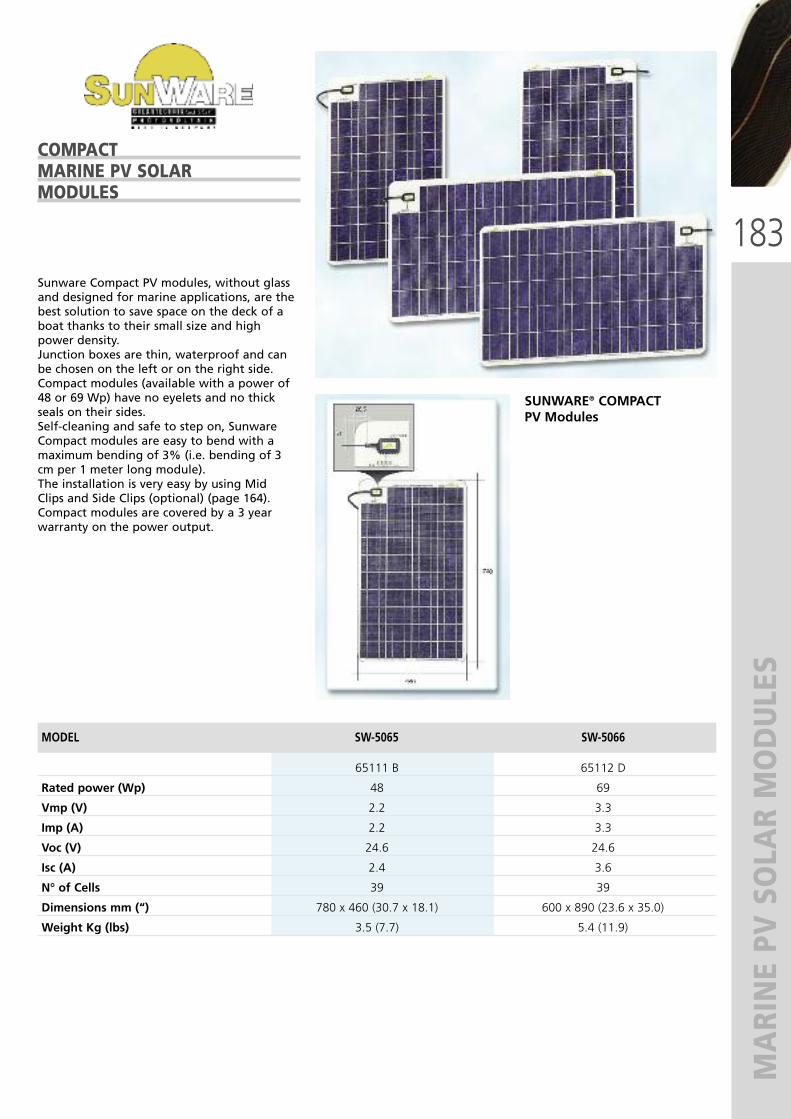
183
MARINE PV SOLAR MODULES
Sunware Compact PV modules, without glassand designed for marine applications, are thebest solution to save space on the deck of aboat thanks to their small size and highpower density.Junction boxes are thin, waterproof and canbe chosen on the left or on the right side.Compact modules (available with a power of48 or 69 Wp) have no eyelets and no thickseals on their sides.Self-cleaning and safe to step on, SunwareCompact modules are easy to bend with amaximum bending of 3% (i.e. bending of 3cm per 1 meter long module).The installation is very easy by using MidClips and Side Clips (optional) (page 164).Compact modules are covered by a 3 yearwarranty on the power output.
COMPACTMARINE PV SOLARMODULES
MODEL SW-5065 SW-5066
65111 B 65112 D
Rated power (Wp) 48 69
Vmp (V) 2.2 3.3
Imp (A) 2.2 3.3
Voc (V) 24.6 24.6
Isc (A) 2.4 3.6
N° of Cells 39 39
Dimensions mm (“) 780 x 460 (30.7 x 18.1) 600 x 890 (23.6 x 35.0)
Weight Kg (lbs) 3.5 (7.7) 5.4 (11.9)
SUNWARE® COMPACTPV Modules

184
REGULATED MODIFIED SINE WAVE INVERTERS
The Sinergex PureWatts series are ratedamong the highest quality regulated modifiedsine wave inverters available. By regulating the AC output, the PW invertersdecrease the level of interference produced bymodified sine wave making the PW seriesperfect for operating equipment like mobileoffice products, televisions, VCR’s, small powertools, laptop computers and many other ACproducts. The PW series offers many otherfeatures like protection against overload, lowbattery voltage, short circuit, and overheating,all with auto-recovery for simple operation.All models have high surge capabilities tostart the toughest equipment.
PUREWATTS SERIESREGULATED MODIFIEDSINE WAVE INVERTERS
The Sinergex PureCharge series are fullyautomatic and intelligent battery chargers.Using microprocessor and switch-modetechnology, the PureCharge battery chargescarefully assess the battery and then deliverthe optimum charge required.
Being a true 3-stage battery charger, thePureCharge delivers charges in bulkabsorption and float stages, each stagedelivering the optimum charge for the bestperformance and power for your battery.
By incorporating the float charge stage, thePureCharge battery charger allows you to setand forget, while your batteries areautomatically maintained.
BATTERY CHARGERSPURE CHARGE SERIES
SERIES PWE 1000 PWE 2000MODEL 12 24 12 24Part No. 64018 G 64020 T 66321 U 66565 Z
DC input Voltage (V) 10-15 20-30 11-15 22-30
Continuous AC power (W) 1000 2000
Surge AC power (W) 2000 4000
Optimum efficiency 85% 85%
Low battery alarm (V) 10.7 for 12 V models & 21.4 for 24 V models
Low battery shutdown @ V 10 for 12 V models & 20 for 24 V models
Low battery auto recovery @ V 12 for 12 V models & 24 for 24 V models
No load current draw (A) 0.9 0.5 1.1 0.7
Dimensions mm (“) 325 x 180 x 90 418 x 180 x 90
(12.8 x 7.1 x 3.5) (16.4 x 7.1 x 3.5)
Weight kg (lbs) 3.0 (6.6) 4.5 (9.9)
MODEL PC 1012 - 64023 Z PC 0524 - 64123 D
Input Voltage (V c.a.) 100 - 240 100 - 240
Input frequency (Hz) 50-60 50-60
Output power (W) 160 80
Output current (A) 10 5
Output Voltage (V) 12 24
Power factor 0.98
Dimensions mm (“) 210x85x50 (8.3x3.3x1.9)
Weight kg (lbs) 0.9 (1.9)
PWE 2000
PWE 1000
PW-RC64022 X
PC1012 BATTERY CHARGER
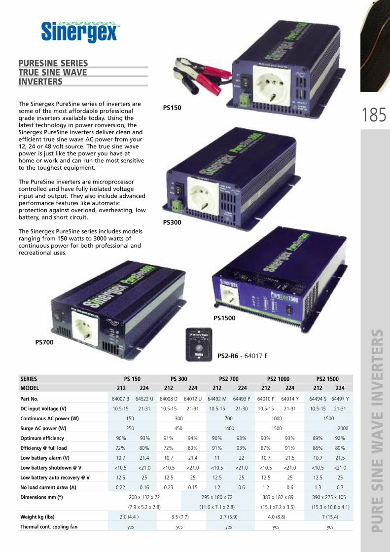
185
PURE SINE WAVE INVERTERS
The Sinergex PureSine series of inverters aresome of the most affordable professionalgrade inverters available today. Using thelatest technology in power conversion, theSinergex PureSine inverters deliver clean andefficient true sine wave AC power from your12, 24 or 48 volt source. The true sine wavepower is just like the power you have athome or work and can run the most sensitiveto the toughest equipment.
The PureSine inverters are microprocessorcontrolled and have fully isolated voltageinput and output. They also include advancedperformance features like automaticprotection against overload, overheating, lowbattery, and short circuit.
The Sinergex PureSine series includes modelsranging from 150 watts to 3000 watts ofcontinuous power for both professional andrecreational uses.
PURESINE SERIESTRUE SINE WAVEINVERTERS
SERIES PS 150 PS 300 PS2 700 PS2 1000 PS2 1500MODEL 212 224 212 224 212 224 212 224 212 224
Part No. 64007 B 64522 U 64008 D 64012 U 64492 M 64493 P 64010 P 64014 Y 64494 S 64497 Y
DC input Voltage (V) 10.5-15 21-31 10.5-15 21-31 10.5-15 21-30 10.5-15 21-31 10.5-15 21-31
Continuous AC power (W) 150 300 700 1000 1500
Surge AC power (W) 250 450 1400 1500 2000
Optimum efficiency 90% 93% 91% 94% 90% 93% 90% 93% 89% 92%
Efficiency @ full load 72% 80% 72% 80% 91% 93% 87% 91% 86% 89%
Low battery alarm (V) 10.7 21.4 10.7 21.4 11 22 10.7 21.5 10.7 21.5
Low battery shutdown @ V <10.5 <21.0 <10.5 <21.0 <10.5 <21.0 <10.5 <21.0 <10.5 <21.0
Low battery auto recovery @ V 12.5 25 12.5 25 12.5 25 12.5 25 12.5 25
No load current draw (A) 0.22 0.16 0.23 0.15 1.2 0.6 1.2 0.6 1.3 0.7
Dimensions mm (“) 200 x 132 x 72 295 x 180 x 72 383 x 182 x 89 390 x 275 x 105
Dimensions (7.9 x 5.2 x 2.8) (11.6 x 7.1 x 2.8) (15.1 x7.2 x 3.5) (15.3 x 10.8 x 4.1)
Weight kg (lbs) 2.0 (4.4 ) 3.5 (7.7) 2.7 (5.9) 4.0 (8.8) 7 (15.4)
Thermal cont. cooling fan yes yes yes yes yes
PS150
PS300
PS700
PS2-R6 - 64017 E
PS1500

186
BATTERY CHARG
E REGULATORS
CHARGE REGULATORS
CHARGE REGULATORS PROSTAR -SUNSAVER MODELS
ProStar - 15 and 30 serie features� 3 digits LCD display reading in sequence:battery current, PV current, loads current.
� Automatic voltage select for either 12 or 24Volt systems.
� Electronic selection of either a sealed orflooded battery.
� Full electronic protection against any sequenceof reversed wire connection.
� PV current (Amps): 15 (ProStar-15) and 30(ProStar-30).
� Load current (Amps): 15 (ProStar-15) and 30(ProStar-30).
� A button will instantly disconnect/connect all PVand loads.
� Load disconnect 11.5V, LVD reconnect 12.6V.� Dimensions mm: 153 X 105 X 55, weight kg 0.34
SunSaver - 6, 10, 20 serie features� Green Led = battery receiving energy from thePV modules, Red Led = load disconnectcondition.
� Full electronic protection against reversed PV,battery or load wire connections.
� Either a flooded or sealed battery can beselected with a simple jumper.
� Encapsulated in epoxy compound for service inharsh environment.
� PV current (Amps): 6.5 (SunSaver-6), 10(SunSaver-10), 20 (SunSaver-20).
� Load current (Amps): 6 (SunSaver-6), 10(SunSaver-10), 20 (SunSaver-20)
� Available in 12 / 24 Volt versions.� Load disconnect 11.5V, LVD reconnect 12.6V� Dimensions mm: 152 X 56 X 33, weight kg 0.23
TECHICAL SPECIFICATION:
MODEL PS15M PS30M PS15M-48V
Part No. 62643W 61737A 63072H
Rated solar current 15 A 30 A 15 A
Rated load current 15 A 30 A 15 A
System voltage 12 V c.c./24 V c.c. 12 V c.c./24 V c.c. 48 V c.c.
Nominal voltage 12 V 24 V 48 V
Self-consumption 22 mA 25 mA 28 mA
TECHICAL SPECIFICATION:
MODEL SS 6 L SS 10 SS 10 L SS 20 L SS 10 L-24
Part No. 61213E 61415B 61192X 61734U 61938L
Rated solar current 6.5 A 10 A 10 A 20 A 10 A
Rated load current 6 A 10 A 10 A 20 A 10 A
Voltage 12 V c.c. 12 V c.c. 12 V c.c. 12 V c.c. 24 V c.c.
LVD YES NO YES YES YES

187
DISPLAYS – MARK
ETING ITEMS
ULTRAFLEX WHEELS DISPLAY
67436 T - Fashionable dismountable display inlight gray painted metal.
ULTRAFLEX®
AND UFLEX®
MARKETING ITEMS
UFLEX and ULTRAFLEX ADHESIVE LABELS:Printed on transparent vinyl
UFLEX - 65360 ZDimensions: 450 x 130 mm (17.71” x 5.12”)
ULTRAFLEX - 65359 RDimensions: 300 x 130 (11.81” x 5.12”)
500 mm
1700 mm

188
DISPLAYS – MARK
ETING ITEMS
FOREX:
65369 U - Dimensions: cm 70 x 100 (2.29’ x 3.28’)
65370 C - Dimensions: cm 119 x 168 (3.9’ x 5.5’)
Please contactour MarketingDepartment toask for the CDwith all FOREXavailable.
ULTRAFLEX® AND UFLEX®
MARKETING ITEMS
UFLEX FLAG - 65226 V:Dimensions: 150 x 225 cm (4.92’ x 7.38’)
UFLEX flags are made of high resistancenylon, with anti-tears double hem,strengthening side sheathing and fixing line.The logo is printed on both sides and they areresistant to sunwear and washing.
65266 V
UFLEX SHIRT:Size S - 65355 GSize M - 65356 JSize L - 65357 LSize XL - 65358 N
UFLEX CAP - 65613 CHeavy cotton with adjustableback strip

Via Milite Ignoto 8A16012 Busalla (GE) - ItalyT +39 010 9620310 F +39 010 [email protected]
UFLEX s.r.l. ULTRAFLEX GROUP
Cover picture: P
h. C
arlo B
orleng
hi. C
ourtesy of Sou
thern Wind Shipyard – SW
100D
S#06 Aca
iaFo
ur