ultramid_polyamide (pa).pdf
TRANSCRIPT

Ultramid®
Polyamide (PA)
(Europe)
BASF Plasticskey to your success
Ultramid®
BASF’s Ultramid® grades are PA molding compounds
on the basis of PA 6, PA 66, various copolyamides such
as PA 66/6 and partially aromatic polyamide. Ultramid®
stands out for its high mechanical strength, stiffness
and thermal stability. Moreover, it is tough at low tem-
peratures, has a favorable sliding friction behavior and
permits problem-free processing. Owing to its excellent
properties, this material has become indispensable in
almost every technical realm for a wide array of compo-
nents and machine elements, also as high-grade elec-
tric insulating material and for many special
applications.

04 - 09
10 -29
30-53
UltrAmid® – thE mAtEriAl oF ChoiCE …
… in today’s automotive sector
… in the electric and electronic industry
… for plumbing and sanitary engineering
4
6
8
thE propErtiES oF UltrAmid®
Product range
Mechanical properties
Thermal properties
Water absorption and dimensional stability
Electrical properties
Fire behavior
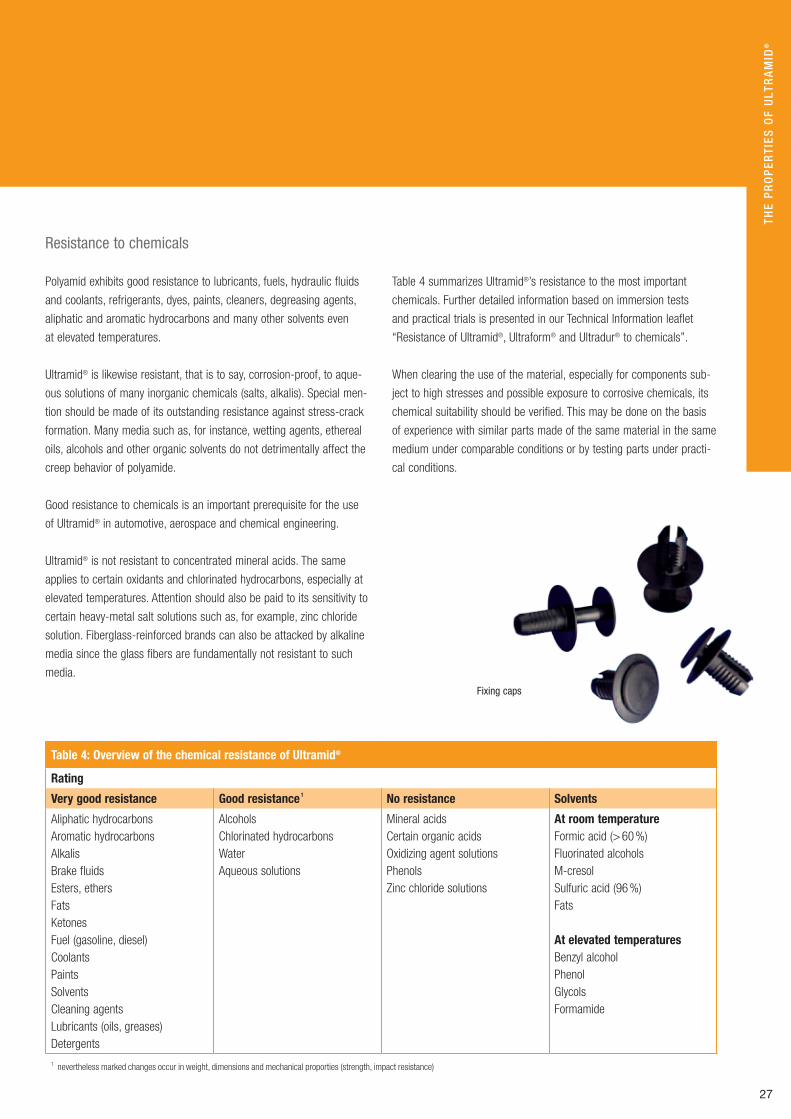
Resistance to chemicals
Behavior on exposure to weather
Behavior on exposure to high-energy radiation
Viscometric and molecular data
10
12
18
22
24
26
27
28
29
thE proCESSing oF UltrAmid®
Processing characteristics
General notes on processing
Injection molding
Processing by injection molding
Machining
Joining methods
Printing, embossing, laser marking, surface coating,
metallizing, surface coloring
Conditioning
Annealing
30
32
34
38
50
52
gEnErAl inFormAtion
Safety notes
Quality management
Quality assurance
Delivery and storage
Colors
Ultramid® and the environment
Services
Product range
Ultramid® Nomenclature
Subject Index
The product range of BASF plastics at a glance
54
55
56
57
58
59
60
61
63
54 - 63

Ultramid® in today’s automotive sector
The very high quality and safety standards in mod-
ern automotive engineering make high demands on
the materials employed. Ultramid® offers high ther-
mal stability, dynamic strength, impact resistance
and long-term performance.
These engineering properties of Ultramid® can be
combined in exceptional manner with intelligent
concepts in today’s automotive industry. Here, on
account of its broadly based functionality Ultramid®
has great potential for the economically optimized
production of structural components and modules.
Further criteria such as lightweight construction,
recyclability and integrated system solutions com-
bining different materials demonstrate the superi-
ority of Ultramid® in comparison with conventional
materials.
Typical Ultramid® applications in automotive engineering:Parts in the engine block and in engine lubrication, e. g. air intake
modules, engine covers, oil sumps, oil filter housings, valve bonnet and
cylinder head covers, camshaft timing gears, chain guides, toothed belt
covers.
Parts and housings for cooling and ventilation systems, e. g. radiator
tanks and heat exchangers for heating purposes, water expansion
tanks, hot-water control valves, thermostat housings, fans, fan frames.
Parts in the fuel supply system, e. g. fuel filter housings, fuel reservoirs
and lines.
Seat
4

5
UlT
rA
Mid
® –
TH
E M
ATE
riA
l O
F c
HO
icE…
Generator end cap lower Bumper Stiffener
Engine cover
Parts in gears, clutches, clutch thrust bearings, gearshifts and speed-
ometer drives, such as bearing cages, gearshift-lever housings, shift
forks, shift links, speedometer drive pinions and gear thrust disks.
Chassis parts, e. g. steering wheels, steering column mountings, roller
bearing cages and fastening clips.
Exterior parts, e. g. structural parts, spoilers, door sills, radiator grills,
exterior door handles, door-mirror housings and wheel covers.
Parts for electrical fittings, e. g. cable harnesses, straps and connec-
tors, headlamp housings, lamp holders and fuse boxes.

6
its excellent electrical insulation properties,
advantageous sliding friction characteristics and
outstanding mechanical strength make Ultramid®
a material which is employed in almost all fields
of power engineering as well as mechanical and
chemical engineering.
Power engineeringHigh-tension insulated switch parts and housings, cable fastenings and
ducts, terminal blocks and connectors, plug-in devices, coil formers,
parts for domestic appliances such as instantaneous water heaters,
solenoid valves, power tool housings and power circuit breakers.
General mechanical and chemical engineeringBearings, gear wheels, transmissions, seals, housings, flanges, clamps,
connectors, bolts, housings for air-pressure gages, housings for pumps
at gas stations and nutting collars.
Materials-handling technologyRollers, pulleys, bushings, transport containers, conveyor belts and
chains.
Precision engineeringControl disks and cams, parts for counting mechanisms, lever and
transmission links, daisy wheels for teletypewriters, mounting frame
parts, control levers and sliding elements.
Ultramid® in the electric and electronic industry
Circuit breaker
plug connector

UlT
rA
Mid
® –
TH
E M
ATE
riA
l O
F c
HO
icE…
7
plug-in connector
Terminal block

8
in plumbing and sanitary engineering Ultramid®
is the material of choice in many applications,
especially for parts subject to high mechanical
loading. Ultramid® has likewise proved to be
outstandingly effective in packaging materials
for foods and cosmetics.
Ultramid® for plumbing and sanitary engineering
PlumbingWall dowels and masonry anchors, fasteners, cable and pipe clamps.
SanitationHandles, fittings, fixtures and fans.
HouseholdSeating furniture, chair frames, furniture casters, cooking utensils
and hammer shafts.
coolant throughputhousing

9
Awning plug
Sanitary set (Hewi)
Measuring stick
UlT
rA
Mid
® –
TH
E M
ATE
riA
l O
F c
HO
icE…

10
The properties of Ultramid®
the most important characteristics of Ultramid® are:
High strength and rigidity
Very good impact strength
Good elastic properties
Outstanding resistance to chemicals
Dimensional stability
Low tendency to creep
Exceptional sliding friction properties
Simple processing
product range
Polyamides 6, 66 and 6T form the basis of the Ultramid® B and A
grades as well as the copolyamide grades. These are supplied in a
variety of molecular weights or melt viscosities, have a range of addi-
tives and are reinforced with glass fibers or minerals. More detailed
information on the individual products may be found in the Ultramid®
range chart.
Ultramid® is the tradename for polyamides supplied
by BASF for injection-molding and extrusion. The
product range includes PA 6 grades (Ultramid® B),
PA 66 grades (Ultramid® A), PA 6 /6T grades
(Ultramid® T) as well as special grades based on
copolyamides, e. g. PA 66 / 6. Ultramid® A is produced
by condensation polymerization of hexamethylene
diamine and adipic acid, Ultramid® B by hydrolytic
polymerization of caprolactam and the copolyamides
by polycondensation or hydrolytic polymerization of
caprolactam, hexamethylene diamine, adipic acid
and terephthalic acid. Ultramid® T is obtained by
polycondensation of caprolactam, hexamethylene
diamine and terephthalic acid. The most important
starting materials, adipic acid, caprolactam, hexa-
methylene diamine and terephthalic acid are ob-
tained from petrochemical feedstocks such as cyclo-
hexane, benzene and toluene.
The Ultramid® range comprises the following groups of products:Ultramid® B
(unreinforced) is a tough, hard material affording parts with good
damping characteristics and high shock resistance even in dry state
and at low temperatures. PA 6 is distinguished by particularly high
impact resistance and ease of processing.
Ultramid® A
(unreinforced) polyamides, is along with Ultramid® T the material with
greatest hardness, rigidity, abrasion resistance and thermostability. It
is one of the preferred materials for parts subject to mechanical and
thermal stresses in electrical, mechanical, automotive and chemical
engineering.
Ultramid® C
This is the name given to copolyamides made from PA 6 and PA 66
modules. They exhibit different properties according to their composi-
tion.
Table 1: Ultramid® grades
Ultramid® PA Chemical structure Melting point [°C]
Ultramid® B 6 polycaprolactam – NH(CH2 )5CO 220
Ultramid® A 66 polyhexamethylene adipamide – NH(CH2 )6NHCO(CH2 )4CO 260
Ultramid® C Copolyamides 66/6 copolymer of hexamethylene diamine adipic acid and caprolactam 243
Ultramid® T Copolyamides 6/6T copolymer of caprolactam hexamethylene diamine and terephthalic acid 298

11
THE
Pr
OP
ErTi
ES O
F U
lTr
AM
id®
5000 10000 15000
A3EG10
T KR 4355 G7
A3EG7, B3ZG8
A3EG6
B3WGM24, B3EG6, B3ZG6
A3EG5, A3HG5, B3EG5
B3EG3, B3ZG3
B3M6
B3S
A3K, A3W
A3R, B3L
Modulus of elasticity [MPa], 23°C, dry state
Fig. 1: Yield stress (tensile stress in the case of reinforced grades) for
selected Ultramid® grades at 23 °C in the dry state (ISO 527)
A3EG10, A3WG10
T KR 4355 G7
A3EG7, B3G8
A3EG6, A3X2G10, B3EG6 A3EG5, A3X2G7, B3EG5, B3ZG6
A3X2G5
B3EG3
B3WGM24
T KR 4350
A3K, B3S
B3M6
A3R
B3L
A3Z
Yield stress / Tensile stress [MPa], 23°C, dry state
50 100 150 200 250
Fig. 2: Modulus of elasticity for selected Ultramid® grades at 23 °C
in the dry state (ISO 527)
Ultramid® T
This class of partly aromatic copolyamides possesses very high ther-
mostability (melting point 298 °C), rigidity, dimensional stability and
constant mechanical properties under conditions of varying humidity.
Glass-fiber reinforced Ultramid®
These materials are distinguished by high mechanical strength, hard-
ness, rigidity, thermostability and resistance to hot lubricants and hot
water. Parts made from them have particularly high dimensional stabil-
ity and creep strength. Glass-fiber reinforced Ultramid® T is moreover
exceptional for its extraordinarily high heat resistance (290 °C).
Reinforced grades with flame retardants
Ultramid® grades treated in this way including C3U, A3X2G5, A3X2G7,
A3X2G10, B3UG4 and T KR4365 G5 are particularly suitable for elec-
trical parts required to meet enhanced specifications for fire safety and
tracking current resistance.
Mineral-filled Ultramid®
The special advantages of these materials lie in increased rigidity, good
dimensional stability, low tendency to warp, smooth surfaces and good
flow characteristics.

12
The properties of Ultramid®
mechanical properties
The Ultramid® product range includes grades with many combinations
of mechanical properties.
One particular feature of the unreinforced grades is the ideal combina-
tion of moderate strength, rigidity and creep strength while impact
resistance and sliding friction properties are excellent.
These advantages are attributable to the partially crystalline structure
and the strong cohesive forces between molecules brought about by
hydrogen bonding between neighboring amido groups.
The reinforced grades offer high rigidity, high creep strength, hardness
and dimensional stability while resistance to heat and heat aging are
outstanding.
A3EG10
A3WG3
A3K
T KR 4355 G7
A3EG6
Temperature [°C]
Shea
r m
odul
us [
MPa
]
-50 0 50 100 150 200 250 300 100
101
102
103
Fig. 4: Shear modulus of Ultramid® A and T grades as a function of
temperature (DIN 53445, dry)
Moisture content [%]
0 1 2 3 4 5 6 7 8 9
20
40
60
80
100
120
140
160
180
200
220 Temperature 23°C
T KR 4355 G7
A3EG7 T KR 4350
B3EG6
Tens
ile s
tres
s [M
Pa]
A3K
B3S
A3EG5
Fig. 3: Tensile stress (yield stress in the case of unreinforced grades)
for Ultramid® as a function of moisture content at 23 °C (ISO 527)
plug connector

13
THE
Pr
OP
ErTi
ES O
F U
lTr
AM
id®
Shea
r m
odul
us [
MPa
]
100
101
102
103
-50 0 50 100 150 200 250
B3EG6
B35EG3
B3M6
B3K
Temperature [°C]
Fig. 5: Shear modulus of Ultramid® B grades as a function of
temperature (DIN 53445, dry)
20-20-40 0 40 60 80 100 120 140 160
10000
12000
14000
16000
8000
6000
4000
2000
0
Mod
ulus
of
elas
tici
ty [
MPa
]
Temperature [°C]
A3WG10, A3EG10
A3WG7, A3EG7
A3WG5, A3EG5, A3HG5
Fig. 6: Modulus of elasticity of reinforced Ultramid® A grades as a
function of temperature (Flexural test ISO 178, dry)
20-20-40 0 40 60 80 100 120 140 160
10000
12000
14000
16000
8000
6000
4000
2000
0
Mod
ulus
of e
last
icity
[MPa
]
Temperature [°C]
B3WG6, B3EG6
B3WG5B3WGM24
B3EG3, B35EG3
B3M6
Fig. 7: Modulus of elasticity of reinforced Ultramid® B grades as a
function of temperature (Flexural test ISO 178, dry)
T KR 4350
T KR 4355 G7
A3K
A3WG7
20-20-40 0 40 60 80 100 120 140 160
10000
12000
14000
16000
8000
6000
4000
2000
0
Mod
ulus
of
elas
tici
ty [
MPa
]
Temperature [°C]
Fig. 8: Tensile modulus of elasticity (ISO 527) of Ultramid® T compared
with that of Ultramid® A as a function of temperature in the dry state

The properties of Ultramid®
The product range can be classified by six groups according to the modulus of elasticity: Impact-modified unreinforced grades 1.500 - 2.000 MPa
Unreinforced grades 2.700 - 3.500 MPa
Mineral-filled, impact-modified grades (+ GF) 3.800 - 4.600 MPa
Mineral-filled grades (+ GF) 3.800 - 9.300 MPa
Impact-modified, glass-fiber reinforced grades 5.200 -11.200 MPa
Glass-fiber reinforced grades 5.200 -16.800 MPa
The mechanical properties are affected by the temperature, time and
moisture content and by the conditions under which the test speci-
mens were prepared.
Ultramid® T is exceptional here in that its mechanical properties are
largely independent of variations in surrounding moisture.
In the case of the reinforced grades additional factors having a signifi-
cant effect on properties are, for example, the glass-fiber content, the
orientation, average length and length distribution of the fibers, and the
pigmentation.
The yield stress of dry, unreinforced Ultramid® ranges from 70 to 100
MPa while that of the reinforced grades rises as high as 250 MPa.
The behavior under short-term uniaxial tensile stress is presented as
stress-strain diagrams (cf. Figs. 9 -11) in which the effects of tempera-
ture, reinforcement and moisture content are illustrated.
High creep strength and low tendency to creep are also exhibited,
especially in the reinforced grades.
Impact strength, low-temperature impact strengthPolyamides are very tough materials. They are suitable for parts
required to exhibit high resistance to fracture. Standard test values
generally determined under different conditions are used to character-
ize their impact behavior (cf. the Ultramid® range chart).
Although the values are not directly comparable with one another
due to the differing test setups, test specimen dimensions and notch
shapes, they do allow comparison of molding materials within the indi-
vidual product groups.
Tests on finished parts are indispensable for the practical assessment
of impact behavior. The falling weight test, for example, carried out
on housings, sheets or test boxes (cf. Fig. 12) in conformity with
DIN 53443, Part 1, has proved to be effective for this purpose. The
measure of toughness is the fracture energy W50 (J) at which 50 %
of the parts tested fail. On this basis high-impact, unreinforced
Ultramid® grades even in the dry state at 23 °C, and sometimes even
at low temperatures, attain values > 140 J, i. e. the parts do not break
when, for example, a 10 kg weight is dropped on them from a height
of 1.4 m (impact speed = 5.3 m /s).
However, the behavior of Ultramid® when subjected to impact is
affected by many factors, of which the most important are the
shape of the part and the rigidity of the material.
circular connector14

15
Elongation [%]
Tens
ile s
tres
s [M
Pa]
200
150
100
50
100°C
80°C
60°C 23°C
150°C
100°C
80°C
60°C
23°C
T KR 4355 G7Test speed:5 mm/min
T KR 4350 Test speed:50 mm/min
10 8 6 4 2 0 10 8 6 4 2 0
Fig. 11: Stress-strain diagrams for Ultramid® T, dry, in accordance
with ISO 527
THE
Pr
OP
ErTi
ES O
F U
lTr
AM
id®
B3S B3WG5 °C
-20
23
60
100
150
120
0
80
100
120
140
160
180
200
20
40
60
0 2 1 0 1 2
Elongation [%]
Tens
ile s
tres
s [M
Pa]
100
60
23
-20
°C
Fig. 9: Stress-strain diagrams for Ultramid® B3S and B3WG5 (dry)
in accordance with ISO 527 (test speed 2 mm /min)
0
80
100
120
140
160
180
200
0 2 1 0 1
Elongation [%]
Tens
ile s
tres
s [M
Pa]
20
40
60
2
100
60
23
-20
°C
100
120
150
60
23
-20
°C
A3EG5 A3K
Fig. 10: Stess-strain diagrams for Ultramid® A3K und A3EG5 (dry)
in accordance with ISO 527 (test speed 2 mm /min)
>14
Fracture energy W50 [J]
5 10
-20°C
+23°C
A3K, A3W
A4K
B3S
A3Z
B3L
A3K
P
Falling weight
120 (mm)
401,5
r =
1.5
Fig. 12: Impact strength of reinforced Ultramid® at + 23 and - 20 °C
determined in the dry state as the fracture energy W50 in accordance
with DIN 53443, Part 1 (test box, wall thickness = 1.5 mm, uncolored)
The properties of Ultramid®
As can be seen in Fig. 13 there are Ultramid® grades with the most
varied combinations of impact strength and rigidity.
Depending on application, requirements, design and processing, prod-
ucts which are unreinforced, of relatively high molecular weight, glass-
fiber reinforced, mineral-filled or impact modified can be selected each
having an optimum relationship between impact strength and rigidity.
The advice below should also be taken into account when choosing
suitable materials.
Moisture promotes the toughness of Ultramid®, even at low tempera-
tures. In the case of glass-fiber reinforced grades the impact strength
of finished parts decreases as the glass fiber content rises while
strength and the values in the flexural impact test for standardized test
specimens increase. This effect is due to differences in the orientation
of the glass fibers.
Unreinforced products of high molecular weight have proved to be
effective for thick-walled engineering parts required to exhibit high
impact strength.
Even in the dry state the impact-modified, unreinforced Ultramid®-
grades B3L, B3Z, and A3Z exhibit high impact strength. They are
employed when conditioning or intermediate storage for absorption of
moisture are uneconomic or when extremely high notched or low-tem-
perature impact strength are called for.
16
Apart from the particular processing conditions, the geometry of the
molding – with the resultant moments of resistance – and especially
the wall thicknesses and the notch radii also play a major role in deter-
mining the fracture energy. Even the speed and point of impact signifi-
cantly affect the results.
Behavior under long-term static loadingThe static loading of a material for relatively long periods is marked by
a constant stress or strain. The tensile creep test in accordance with
ISO 899 and the stress relaxation test in accordance with DIN 53441
provide information about extension, mechanical strength and stress
relaxation behavior under sustained loading.
The results are presented as creep curves, creep modulus curves,
creep stress curves and isochronous stress-strain curves (Figs. 14 -15).
The graphs for standard conditions (in accordance with
DIN 50014-23/50-2) reproduced here are just a selection from
our extensive computer-based results.
Further values and diagrams for different temperature and atmospheric
conditions can be requested from the Ultra-Infopoint or found in the PC
program “Campus”. Design data obtained from uniaxial tensile loads
can also be used to assess the behavior of a material under multiaxial
loads.
Behavior under cyclic loads, flexural fatigue strengthEngineering parts are also frequently subjected to stress by dynamic
forces, especially alternating or cyclic loads, which act periodically in
the same manner on the structural part. The behavior of a material
under such loads is determined in long-term tests using tensile and
compressive loading (specimen shape in accordance with DIN 53455,
No. 3) alternating at up to very high load-cycle rates. In doing so the
temperature of the specimen is maintained at exactly the temperature
specified by controlling the frequency (BASF method). The results are
presented in Woehler diagrams obtained by plotting the applied stress
against the load-cycle rate achieved in each case (see Fig. 16).
program selector switch

17
THE
Pr
OP
ErTi
ES O
F U
lTr
AM
id®
NK 23/50
Tens
ile s
tres
s [M
Pa]
3
4
3
4
5
0 1 2 0 1 2
10 h
120 °C
10 h
10
10
10
10 10
extrapolated
16
14
12
10
8
6
4
2
Elongation [%]
Fig. 14: Isochronous stress-strain curves for Ultramid® A3K in
accordance with ISO 899 under standard atmospheric conditions
(23/50) and at 120 °C (in the dry state)
Tens
ile s
tres
s [M
Pa]
Elongation [%]
10
120°C
10 h
10
10
5x10 h
10 10 NK 23/50
0 1
extrapolated
2 0 1 2
100
90
80
70
60
50
40
30
20
10
3 4
3
4
4
Fig. 15: Isochronous stress-strain curves for Ultramid® A3WG10 in
accordance with ISO 899 under standard atmospheric conditions
(23 / 50) and at 120°C (in the dry state)
Modulus of elasticity [MPa]
Frac
ture
ene
rgy
W50
[J]
B3ZG3 B3ZG6
B35EG3
B3WM602 T KR 4355 G7
B3WGM24 A3WG6
0 2000 4000 6000 8000 12000 10000
10
20
30
40
50
Fig. 13: Impact strength, determined as the fracture energy W50 in
accordance with DIN 53443, Part 1 (cf. Fig. 12), and modulus of
elasticity (ISO 527) of reinforced Ultramid® at 23 °C in the dry state
Stre
ss a
mpl
itud
e [M
Pa]
1000Load-cycle rate
4
Temperature 23°C1 = A3WG7 2 = B3WG6 3 = A3HG5
1 2 3
180 160
140
120
100
80
60
40
10 000 100 000 1000 000 10 000 000
Fig. 16: Flexural fatigue strength of glass-fiber reinforced Ultramid® A,
B and T. Stress amplitude as a function of load-cycle rate at standard
moisture content (standard conditions 23 / 50)

18
The properties of Ultramid®
When applying the test results in practice it has to be taken into
account that at high load alternation frequencies the workpieces may
heat up considerably due to internal friction.
In such cases the curves measured at higher temperatures have to be
used (Fig. 17).
Tribological propertiesA smooth, tough and hard surface, crystalline structure, high thermo-
stability and resistance to lubricants, fuels and solvents make Ultramid®
an ideal material for parts subjected to sliding friction. Its good dry-
running properties are worth pointing out. Whereas metallic materials
tend to jam under dry-running conditions, pairings with Ultramid® run
satisfactorily even without lubrication.
Wear and friction are system properties which depend on many param-
eters, e. g. on the paired materials, surface texture and geometry of the
sliding parts in contact, the intermediate medium (lubricant) and the
stresses due to external factors such as pressure, speed and tempera-
ture.
Wear due to sliding friction
The most important factors determining the level of wear due to sliding
friction and the magnitude of the coefficient of sliding friction are the
hardness and surface roughness of the paired materials, the contact
pressure, the distance traversed, the temperature of the sliding sur-
faces and the lubrication. Fig. 18 shows friction and wear values deter-
mined in a specific tribological system for different Ultramid® grades
having two degrees of surface roughness.
Especially Ultramid® A3R and the mineral-filled grades, are distin-
guished by a low coefficient of sliding friction and low rates of wear
due to sliding friction (rate of wear S in µm / km).
Drop erosion and cavitation
Ultramid® has proved to be superior to aluminum in withstanding wear
stresses of this nature which play a significant role in water pumps for
example.
Jet erosion
Fans and automobile spoilers for example are exposed to this type of
stress which is caused by granular solids entrained in streams of air or
liquid. The advantageous elastic behavior of Ultramid® results in high
resistance in this case.
thermal properties
Ultramid® has extraordinarily high melting temperatures:
Ultramid® B: 220 °C
Ultramid® C: 243 °C
Ultramid® A: 260 °C
Ultramid® T: 298 °C
Due to its semicrystalline structure and strong hydrogen bonding
Ultramid® retains its shape even at elevated temperatures close to
the melting range.
Ultramid® stands out among other partially crystalline thermoplastics
due to its low coefficients of linear expansion.
The reinforced grades in particular exhibit high dimensional stability
when exposed to temperature changes. In the case of the glass-fiber
reinforced grades, however, linear expansion depends on the orienta-
tion of the fibers as is evident from Fig. 19.
Stre
ss a
mpl
itud
e [M
Pa]
Load-cycle rate
4
Temperature 90°C1 = A3WG7 2 = B3WG6 3 = A3HG5
1 2 3
180 160
140
120
100
80
60
40
1000 10 000 100 000 1000 000 10 000 000
Fig. 17: Flexural fatigue strength of glass-fiber reinforced Ultramid® A
and B. Stress amplitude as a function of load-cycle rate (90 °C)

19
THE
Pr
OP
ErTi
ES O
F U
lTr
AM
id®
Mean depth of roughnessMean depth of roughnessRz = 0,15-0,20 µm Rz = 2,0-2,6 µm
Coef
ficie
nt o
f sl
idin
g fr
icti
on [
µ]
Wear rate S [µm/km]
0.2
0.4
0.6
0.8
1.0
0.2
0.4
0.6
0.8
1.0
0 1 2 3 4 5 0 2 4 6 8 10
A3R
A3K
A3WG6 A3WG6
A3K
A3R
Fig. 18: Coefficient of sliding friction and wear rates of unreinforced
and fiber reinforced Ultramid®.
Tribological system: pin-on-disk apparatus, p = 1 MPa, v = 0.5 m / s
Paired material: Cr 6 / 800 HV steel, technically dry
80 100 12040 60
Line
ar e
xpan
sion
[%
]
Temperature [°C]
-20 0 20-0.4
-0.2
0
0.2
0.4
0.6
0.8
1.0
1.2
B3 A3
T KR 4350 perpendicular to melt flow:T KR 4355 G5
A3WG... u. B3WG...
parallel to melt flow:T KR 4355 G5
A3WG... u. B3WG...
Fig. 19: Linear expansion of Ultramid® grades as a function of
temperature (in the dry state)
Truck-engine sump

20
The properties of Ultramid®
Behavior on application of heatApart from its product-specific thermal properties the behavior of
components made from Ultramid® on exposure to heat also depends
on the duration and mode of application of heat and on the mechani-
cal loading. The design of the parts also has an effect. Accordingly, the
thermostability of Ultramid® parts cannot be estimated simply on the
basis of the temperature values from the various standardized tests no
matter how valuable the latter might be for guidance and comparisons.
The shear modulus and damping values measured as a function of
temperature in torsion pendulum tests in accordance with DIN 53445
afford valuable insight into the temperature behavior. Comparison of
the shear modulus curves (Figs. 4 and 5) provides information about
the different thermomechanical effects at low deformation stresses and
speeds. Based on practical experience the thermostability of parts pro-
duced in optimum manner is in good agreement with the temperature
ranges determined in the torsion tests in which the start of softening
becomes apparent.
The test for heat resistance in accordance with VDE 0470, § 4b
(ball indentation test), is usually specified for applications in electrical
equipment. The requirements of this test at 125 °C for supports for
voltage-carrying parts are met by finished parts made from all grades
of Ultramid®. The reinforced grades are recommended for this
purpose.
Heat aging resistanceStabilized Ultramid® grades with K, E, H or W as the second letter in
their name are suitable for parts subjected to long-term-exposure to
high temperature.
Table 2 sets out the characteristics and effectiveness of this stabiliza-
tion with reference to the example of Ultramid® A.
Two characteristics are suitable for comparing heat aging resistance,
i. e. the response of the various Ultramid® grades to the long-term
action of heat. These are the temperature index (TI) for exposure
to heat for 5.000 or 20.000 hours and the halving interval (HIC) in
accordance with IEC 216. In the case of Ultramid® the decline in
tensile strength and impact strength to the limiting value (50 % of
the initial value) are suitable evaluation criteria.
Diagrams of the thermal resistance, i. e. graphs of the times measured
at different temperatures for the initial value to change to the limiting
value, are reproduced by way of example in Fig. 20 for some unre-
inforced Ultramid® grades. The TI values are also listed in the typical
values table in the Ultramid® range chart.
tension pulleys

Table 2: Stabilized Ultramid® A grades
Code K E H W
Example without GF A3K A3W
Example with GF A3EG6 A3HG5 A3WG6
Natural color colorless colorless brown greenish
Effectiveness
Time taken at 120°C for initial tensile strengh to drop by 50 %
without GF days 200 700 1000
with GF days > 1500 > 2000 > 2000
Hot water coolants
(•) •* (•)
Outdoor exposure • • • •
Engine & transmission oils • • •• •
Dielectric properties • • • (•)
•• = particularlysuitable • = suitableorfavourable (•) = suitable,butwithlimitations
– not recommended * A3HG6HR
THE
Pr
OP
ErTi
ES O
F U
lTr
AM
id®
Temperature [°C]
Day
s
Hou
rs 100 000
10 000
1000
100
10
1
80 100 120 140 160 180
0.1
1
10
100
1000
A3K A3W B3S T KR 4350
Fig. 20: Heat aging resistance of unreinforced Ultramid® grades under
the action of heat (graphic temperature profile) in accordance with
IEC 216 -1; limiting value of property: 50 % tensile strength
Hammer drill 21

22
The properties of Ultramid®
Heat aging resistance in hot lubricants, coolants and solvents
The widespread application of Ultramid® in engineering, especially in
automotive engineering, e. g. in engine oil circuits and gearboxes, is
based on its outstanding long-term resistance to hot lubricants, fuels
and coolants and to solvents and cleaning agents. Fig. 21 shows how
the flexural and impact strength of Ultramid® A and T are affected by
immersion in hot lubricants (120 °C) and coolants. H- and W-stabilized
grades are particularly resistant to lubricants and hot coolants.
A3HG6 HR has proved to be particularly successful in applications
in automobile cooling circuits.
Information on the temperature limits for Ultramid® exposed to the
action of these and other chemicals is provided by the Technical Infor-
mation leaflet “Resistance of Ultramid®, Ultraform® and Ultradur® to
chemicals”.
Duration of immersion [hours]
Impa
ct s
tren
gth
[kJ/
m2 ]
Flex
ural
str
engt
h [M
Pa]
6
5
18
7
43
2
2
1
43
5
6
0 1000 1500 2000
120110
500
1009080706050403020
80100120140160180200220240260
1 = A3HG5 in Shell engine oil HD 15 w 40 at 120 °C
2 = A3HG5 in Shell Spirax HD 90 at 120 °C
3 = A3HG5 in Shell Spirax EP 90 at 120 °C
4 = A3HG5 in Klüber Isoflex LDS lubricating grease at 120 °C
6 = A3HG6 HR in Glysantin / water (1:1) at 108 °C
5 = A3EG6, A3WG6 in Glysantin / water (1:1) at 106 °C
7 = T KR 4355 G7 Shell Spirax at 120 °C
8 = T KR 4355 G7 in Glysantin / water (1:1) at 110 °C
Fig. 21: Flexural strength (ISO 178) and impact strength (ISO 179) of Ultramid® A3HG5, A3EG6, A3WG6 and T KR 4355 G7 in hot lubricants
and coolants as a function of immersion temperature (measurements at 23 °C) and duration of immersion
Water absorption and dimensional stability
A special characteristic of polyamides in comparison with other thermo-
plastics is their water absorption. In water or in moist air depending on
its relative humidity and dependant on time, temperature and wall
thickness moldings absorb a certain quantity of water so that their
dimensions increase slightly. The increase in weight on saturation
depends on the Ultramid® grade and is listed in the tables in the range
chart. Fig. 22 shows how the absorption of moisture on saturation
depends on the relative humidity.

23
Relative humidity [%]
Moi
stur
e ab
sorp
tion
[%
]
Temperature range 10°C-70°C
B3S A3K B3EG6 A3EG6
100 80 0 20 40 60
2
4
6
8
Fig. 22: Equilibrium moisture content of Ultramid® as a function of
relative humidity in the temperature range 10 °C - 70 °C
(scatter: ± 0.2 to 0.4 % absolute)
THE
Pr
OP
ErTi
ES O
F U
lTr
AM
id®
Wat
er a
bsor
ptio
n [%
]
Time [d]s = 2 mm
in waterNK 23/50
A3K, 20°C
A3EG6, 20°C A3EG6, 80°C
T KR 4355 G7, 80°C
A3K
T KR 4355 G7A3EG6
t
250 200 150 100 80 60 40 20 10 1 0
10
8
6
4
2
Fig. 24: Water absorption of Ultramid® A and T as a function of
storage time and the conditioning parameters (thickness of
specimen 2 mm)
t
Time [d]s = 2 mm
Wat
er a
bsor
ptio
n [%
]
0
10
8
6
4
2
250 200 150 100 80 60 40 20 10 1
in waterNK 23/50
B3EG6, 80°C
B3EG6, 20°C
B3S, 20°C
B3S
B3EG6
Fig. 23: Water absorption of Ultramid® B as a function of storage time
and the conditioning parameters (specimen thickness 2 mm)
Figs. 23 - 24 show the water absorption of Ultramid® as a function of
storage time under various test conditions. It is evident from these that
in comparison with the PA 6 and PA 66 grades Ultramid® T affords
distinct advantages with respect to water absorption.
As can be seen from the Ultramid® range chart, water absorption
results in increased impact strength, elongation at break and tendency
to creep whereas strength, rigidity and hardness decrease.
Provided that the water is uniformly distributed in the molding,
Ultramid® A and Ultramid® B undergo a maximum increase in volume of
about 0.9 % and a mean increase in length of 0.2 to 0.3 % per 1 % of
absorbed water. The dimensional change of the glass-fiber reinforced
grades amounts to less than 0.1 % per 1 % in the direction of the fiber
orientation (longitudinally). As a result of this the dimensions of these
grades, like those of the mineral-filled grades, remain particularly con-
stant when humidity varies.

24
The properties of Ultramid®
Electrical properties
The paramount importance of Ultramid® in electrical engineering, espe-
cially for electrical insulating parts and housings in power engineering,
is attributable to its good insulating properties (volume resistance
and surface impedance) combined with its impact strength and creep
strength as well as its advantageous properties in relation to heat and
aging. As a result Ultramid® is numbered among the high-performance
insulating materials.
Wherever there are high demands on fire properties the flameretar-
dant grades A3X2G…, T KR 4365 G5, C3U, B3UG4 and A3UG5 are
preferably used. The following points should be noted in relation to
electrical properties.
The products are characterized by a high tracking current resi-
stance which is only slightly impaired by the moisture content of
the material.
The specific volume resistance and the surface impedance are very
high; these values decline at elevated temperatures and also when
the water content is relatively high.
As for all electrical insulating materials when used in harsh
conditions continual wetting due to condensation must be
prevented by appropriate design measures.
Unfavorable operating environments such as hot pockets combined
with high air humidity, moist, warm conditions or poor ventilation can
adversely affect the insulating properties.
For the above reasons the performance of the components should
be carefully checked for each application. The values of the electrical
properties are listed in the range chart.
Figs. 25 -27 show the effect of temperature and moisture on the
dielectric strength and specific volume resistivity of Ultramid® A3X2G…
and T KR 4355 G7.
Insulating materials are tested for the production of deposits harmful
to electrical contacts in accordance with the preliminary FTZ standard
547 PV1 (FTZ = Fernmeldetechnisches Zentralamt = German central
telecommunications technology office). The change in resistance of
relay contacts is measured after these together with the insulating
material have been stored in a desiccator at a temperature of 70 °C.
Moisture content [%]
Die
lect
ric
stre
ngth
Ed [
kV/m
m]
A3EG6
25°C
80°C
65°C
10
0 1 2 3 4 5 6 7 8
20
30
Fig. 25: Dielectric strength of Ultramid® A3EG6 at different
temperatures as a function of moisture content (DIN 53481;
wall thickness 3 mm)
The Ultramid® grades which on the basis of the results of this standard
test are suitable for electrical engineering applications are rated as not
harmful to electrical contacts.
The Ultramid® grades A3X2G… and T KR 4365 G5 contain a special
stabilizer to prevent the formation of red phosphorus decomposition
products which can occur some in polyamides with phosphorus-based
flame retardants. As is the case with all insulators parts made from
Ultramid®, especially those intended for use under extreme conditions
of heat and humidity, must be carefully designed and tested to ensure
they operate reliably.
Overviews, tables and examples illustrating the use of Ultramid® in
electrical, power and telecommunications engineering are presented in
the brochure “Halogen-free flame-retardant Ultramid® grades”.

25
THE
Pr
OP
ErTi
ES O
F U
lTr
AM
id®
Temperature [°C]
Spec
ific
volu
me
resi
stiv
ity
[Ohm
· cm
]
1 = A3EG6, A3HG5 2 = A3X2G5, A3WG6
dry2% moisturesaturated
105
106
107
108
109
1010
1011
1012
1013
1014
1015
1016
40 60 80 100 120 140 160
1
1
1
2
2
2
Fig. 26: Specific volume resistivity of glass-fiber reinforced Ultramid® A
with different moisture contents as a function of temperature
(DIN 53482)
Spec
ific
volu
me
resi
stiv
ity
[Ohm
· cm
]
T KR 4355 G7 (dry)
10 7
10 8
10 9
10 10
10 11
10 12
10 13
10 15
10 16
10 14
Temperature [°C]
T KR 4355 G7 (moist)
140 40 80 120 160 60 100 20 180 200
Fig. 27: Specific volume resistivity of glass-fiber reinforced Ultramid® T
in the dry state and following exposure to moist air (conditioned) as a
function of temperature (IEC 93)
Online paintable car parts

26
The properties of Ultramid®
Transportation
DIN 75200 is the test method used in automotive engineering for
determining the flammability of materials in the passenger compart-
ment of automobiles. Sheet specimens arranged horizontally are tested
with a Bunsen burner flame, a method which is largely equivalent
to FMVSS302 (USA). As can be seen in Table 3 Ultramid® meets the
requirements.
Construction industry
The testing of building materials for the construction industry is carried
out in accordance with DIN 4102, Part 1, “Fire behavior of building
materials and building parts”. Sheets of unreinforced and glass-fiber
reinforced Ultramid® (thickness ≥ 1 mm) are rated as normally flam-
mable building materials1) in Building Materials Class B 2 (Designation
in accordance with the building regulations in the Federal Republic of
Germany).
Fire behavior
General notesUltramid® A and B gradually start to decompose at a temperature
above 310 °C, and Ultramid® T above 350 °C. In the temperature range
of 450 °C to 500 °C flammable gases are given off which continue to
burn after ignition. These processes are affected by many factors so
that, as with all flammable solid materials, no definite flash point can
be specified. The decomposition products have the odor of burnt horn.
The decomposition products from charring and combustion are mainly
carbon dioxide and water and depending on the supply of oxygen small
amounts of carbon monoxide, nitrogen and small amounts of nitro-
gen-containing compounds.Toxicological studies have shown that the
decomposition products formed in the temperature range up to 400 °C
are less toxic than those from wood, while at higher temperatures, the
toxicity is comparable. At higher temperatures they are equally toxic.
The calorific value Hu according to DIN 51900 lies in the range of
29.000 to 32.000 kJ / kg (unreinforced grades).
TestsElectrical engineering
Various material tests are carried out to assess the fire behavior of
electrical insulating materials.
In Europe the incandescent wire test in accordance with IEC 60695 is
often specified. Table 3 shows the classifications for Ultramid® grades.
A further test for rod-shaped samples is the rating in accordance with
“UL 94-Standard Tests for Flammability of Plastic Materials for Parts
in Devices and Appliances” from the Underwriters Laboratory Inc./USA.
On the basis of this test method almost all unreinforced grades fall
into the UL 94V-2 class. The unreinforced, flame-retardant grade
Ultramid® C3U attains the rating UL 94V - 0. Moreover, IEC 60335
requires that household appliances which operate unattended and
through which high currents flow have to pass the GWIT 775 (Glow-
Wire Ignitability Test).
The reinforced grades require the incorporation of a flame retardant in
order to achieve a correspondingly favorable rating. Examples include
the Ultramid® grades A3X2G…A3UG5 (with glass-fiber reinforcement),
B3UG4 and Ultramid® T KR 4365 G5 as well as special mineralfilled
grades. The fire-protection properties are summarized in Table 3.
Table 3: Fire performance
Ultramid® UL 94 Incandescent wire test1 IEC 60695 2-12
FMVSS 302 (d ≥ 1 mm)
A3K V-2 (0.4 mm) 960 °C2 pass
B3S V-2 (1.5 mm) 960 °C2 pass
A3EG… reinforced HB 650 °C pass
B3EG… reinforced HB 650 °C pass
A3X2G10 V-0 (1.6 mm) 960 °C pass
A3X2G5/G7 V-0 (0.8 mm) 960 °C pass
B3UG4 V-2 (0.8 mm) 960 °C pass
C3U V-0 (0.4 mm) 960 °C pass
T KR 4365 G5 V-0 (0.8 mm) 960 °C –
A3UG5 V-0 (0.8 mm) 960 °C –
1 Material testing conducted on sheets (thickness of 1mm2 Undyed; dyeing can have an influence.
27
THE
Pr
OP
ErTi
ES O
F U
lTr
AM
id®
resistance to chemicals
Polyamid exhibits good resistance to lubricants, fuels, hydraulic fluids
and coolants, refrigerants, dyes, paints, cleaners, degreasing agents,
aliphatic and aromatic hydrocarbons and many other solvents even
at elevated temperatures.
Ultramid® is likewise resistant, that is to say, corrosion-proof, to aque-
ous solutions of many inorganic chemicals (salts, alkalis). Special men-
tion should be made of its outstanding resistance against stress-crack
formation. Many media such as, for instance, wetting agents, ethereal
oils, alcohols and other organic solvents do not detrimentally affect the
creep behavior of polyamide.
Good resistance to chemicals is an important prerequisite for the use
of Ultramid® in automotive, aerospace and chemical engineering.
Ultramid® is not resistant to concentrated mineral acids. The same
applies to certain oxidants and chlorinated hydrocarbons, especially at
elevated temperatures. Attention should also be paid to its sensitivity to
certain heavy-metal salt solutions such as, for example, zinc chloride
solution. Fiberglass-reinforced brands can also be attacked by alkaline
media since the glass fibers are fundamentally not resistant to such
media.
Table 4 summarizes Ultramid®’s resistance to the most important
chemicals. Further detailed information based on immersion tests
and practical trials is presented in our Technical Information leaflet
“Resistance of Ultramid®, Ultraform® and Ultradur® to chemicals”.
When clearing the use of the material, especially for components sub-
ject to high stresses and possible exposure to corrosive chemicals, its
chemical suitability should be verified. This may be done on the basis
of experience with similar parts made of the same material in the same
medium under comparable conditions or by testing parts under practi-
cal conditions.
Table 4: Overview of the chemical resistance of Ultramid®
Rating
Very good resistance Good resistance 1 No resistance Solvents
Aliphatic hydrocarbons Aromatic hydrocarbons Alkalis Brake fluids Esters, ethers FatsKetones Fuel (gasoline, diesel) Coolants Paints Solvents Cleaning agents Lubricants (oils, greases) Detergents
Alcohols Chlorinated hydrocarbons Water Aqueous solutions
Mineral acids Certain organic acids Oxidizing agent solutions Phenols Zinc chloride solutions
At room temperatureFormic acid (> 60 %) Fluorinated alcohols M-cresol Sulfuric acid (96 %) Fats At elevated temperaturesBenzyl alcohol Phenol Glycols Formamide
1 nevertheless marked changes occur in weight, dimensions and mechanical proporties (strength, impact resistance)
Fixing caps

The properties of Ultramid®
Behavior on exposure to weather
Ultramid® is suitable for outdoor applications. Different grades come
into consideration depending on requirements.
The unreinforced, stabilized grades with K and H identifiers are highly
resistant to weathering even when unpigmented. Suitable pigmentation
increases outdoor performance still further, best results being achieved
with carbon black.
The reinforced grades also exhibit good resistance to weathering.
Stabilized grades, e. g. Ultramid® B3EG5, can be relied upon to last
for well over five years.
Since the glass fibers near the surface are attacked more severely,
glass fiber reinforced grades may exhibit some surface texture and
color changes with short exposures. After several years exposure abra-
sion of the surface layer by up to several tenths of a millimeter can
be expected. However experience shows that this does not cause any
appreciable impairment of the mechanical properties.
Specially UV-stabilized grades and products with a high carbon black
content have proven to be very effective for outdoor applications, such
as housings for door mirrors on automobiles, in which surface quality
must not change even after several years use.
28
Behavior on exposure to high-energy radiation
Unreinforced Ultramid® polyamide exhibits moderate resistance to radi-
ation. The change in properties of unreinforced Ultramid® resins due to
high-energy radiation varies with the grade of resin exposed.
Some properties already change at low doses whereas others change
scarcely at all even at high doses. Irradiation with a 2 MeV electron
beam (high dose rate) gives rise to the changes in properties shown in
Fig. 28 for Ultramid® A3 grades as a function of the absorbed
energy dose.
In the range up to 10.000 kJ / kg (1.000 Mrad) the electrical properties
(dielectric constant, loss factor, tracking current resistance) are
practically unaffected.
The glass-fiber reinforced grades, including those containing a flame
retardant, are extraordinarily resistant to radiation. A radiation dose
of 2.000 kJ / kg for example only results in a drop in impact strength of
15 to 30 %. A gamma-ray dose of 25 kJ / kg has no adverse effects on
the mechanical properties of Ultramid®. Uncolored or white-pigmented
parts assume a slight yellow tinge.
lower Bumper Stiffener

29
THE
Pr
OP
ErTi
ES O
F U
lTr
AM
id®
Viscometric and molecular data
The solution viscosity of polyamides can be determined by various
standard methods using different solvents. Table 5 gives the viscosity
numbers and other viscosity-related values as well as molecular data
and melt viscosities for various Ultramid® base polymers. The viscosity
number and the melt volume flow rate MVR 275 / 5 or MVR 325 / 5 of
the individual grades are given in the range chart.
50
100
200
150
250
50
40
30
20
10
Modulus of elasticity
Tensile strength
Impact strength Elongation at break
A3 grades unreinforced
A3WG7 A3X2G5
A3WG5
40 80 120 160
Dose
0 0
1 10
100 1000
[Mrad]10 100
1000 100 000
10 000 1000 000 [kJ/kg]
200 250 0
Perc
enta
ge o
f or
igin
al v
alue
of t
he p
rope
rty
[%]
Impa
ct s
tren
gth
[KJ/
m2 ]
Radiation dose [Mrad]
Fig. 28: Behavior of Ultramid® on exposure to high-energy radiation.
Impact strength (DIN 53453), tensile strength, modulus of elasticity
and elongation at break (DIN 53455) as a function of the absorbed
dose. Irradiation with 2 MeV electron beam, absorbed dose rate
0.5 Mrad /min.
Table 5: Viscometric and molecular data for Ultramid® B, A and T grades (typical values)
Unit B3 B35 B4 A3 A4 T KR 4350
Viscosity number ISO 307 (sulfuric acid)
cm3/g 150 195 250 150 205 130
Viscosity number ISO 307 (formic acid)
cm3/g 143 187 250 134 196 –
Relative viscosity (c =1 g /dl, sulfuric acid)
– 2.7 3.3 4.05 2.6 3.45 2.6
Number average molar mass Mn
– 18000 24000 33000 18000 26000 –
Number average 1) degree of polymerization
– 160 210 290 160 230 –
Melt viscosity at 250 / 280 2) (shear rate=1000 s –1)
Pa · s 140 280 400 130 210 175
MVR 3) (Melt volume rate) DIN-ISO 1133, procedure B at 275°C / 5 kg
cm3
(10 min)130 40 16 150 40 30
1) for Ultramid® A, expressed as 1/2 basic molecule2) Ultramid® B at 250 °C, Ultramid® A at 280 °C, Ultramid® T at 320 °C3) Die L / D = 8.0 /2.1 mm Ø, load 5 or 10 kg, moisture < 0.05 %, Ultramid® T at 325 °C / 5 kg

30
Ultramid® can be processed in principle by all meth-
ods known for thermoplastics. The main methods
which come into consideration, however, are injec-
tion-molding and extrusion. complex moldings are
economically manufactured in large numbers from
Ultramid® by injection-molding.
Information on the extrusion of Ultramid® can be found in the BASF
brochure „Ultramid® grades in extrusion“.
processing characteristics
Melting and setting behaviorThe softening behavior of Ultramid® on heating is shown by the shear
modulus and damping values measured in accordance with DIN 53445
as a function of temperature (Figs. 4 and 5). Pronounced softening only
occurs just below the melting point, from about 270 °C for Ultramid® T,
240 °C for Ultramid® A and about 200 °C for Ultramid® B. Glass-fibers
raise the softening point.
The melt also solidifies within a narrow temperature range which is
about 20 °C to 40 °C below the melting point depending on the rate
of cooling and the Ultramid® grade in question. At the same time there
is a contraction in volume of 3 % to about 15 %. The total volumetric
shrinkage can be read off from the PVT diagrams in Fig. 29.
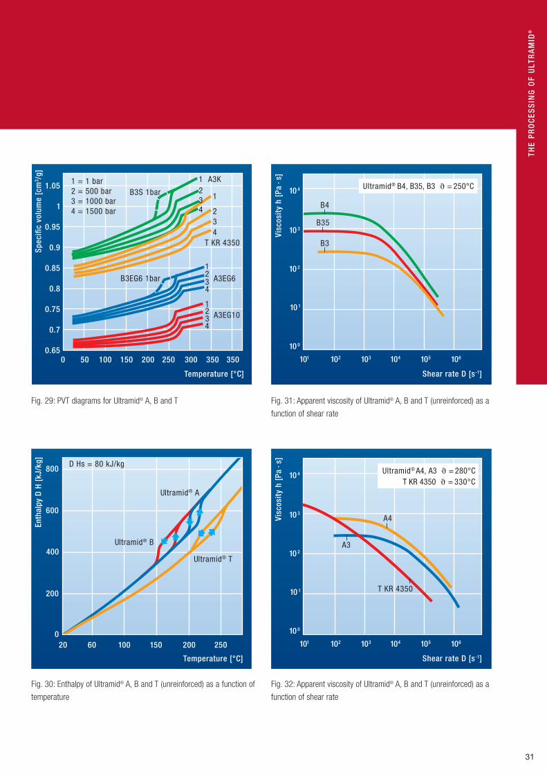
Thermal propertiesThe relatively high specific enthalpy of Ultramid®, shown as a function
of temperature in Fig. 31, requires not only powerful heating elements
for melting, but also somewhat longer setting and cooling times which
are proportional to the square of the wall thickness or diameter.
Melt viscosityThe rheological properties of Ultramid® melts are evaluated on the
basis of viscosity diagrams produced from measurements using a cap-
illary rheometer or on the basis of injection-molding tests.
The processing of Ultramid®
The extrusion method is used to produce films,
semi-finished products, pipes, profiled parts, sheet
and monofilaments. Semi-finished products are for
the most part further machined by means of cutting
tools to form finished molded parts.
In the processing temperature range the Ultramid® grades have a melt
viscosity of 10 to 1.000 Pa · s, the actual value being highly dependent
on temperature and shear rate. The higher the relative molar mass or
the relative solution viscosity (given by the first digit in the name), the
higher is the melt viscosity and the greater the resistance to flow
(Fig. 31). In the case of Ultramid® grades with mineral fillings or glass-
fiber reinforcement the viscosity increases in proportion to the amount
of reinforcing material incorporated.
The melt viscosity can change over time. A rapid drop in viscosity can
occur for example when the melt is too moist, too hot or subjected to
high mechanical shear forces. Oxidation can also cause the viscosity
to fall. All these factors have an effect on mechanical properties and
the heating aging resistance of the finished parts or the semi-finished
products.
Thermostability of the meltsWhen correctly processed the thermostability of Ultramid® melts is
outstanding. Under normal processing conditions the material is not
attacked or modified. Degradation in the polymer chains only occurs
when the residence time is relatively long. The recommended melt tem-
peratures for processing may be found in Table 6 and in the Ultramid®
range chart.
If the melt does not come into contact with oxygen, no noteworthy color
changes occur. Upon exposure to air, for example, when open injection
nozzles are used or in case of interruptions in production, the surface
can already become discolored after a brief time.
31
Ultramid® B
Ultramid® T
Ultramid® A
D Hs = 80 kJ/kg
Temperature [°C]
Enth
alpy
D H
[kJ
/kg]
600
20 150 100 200 25060 0
200
400
800
Fig. 30: Enthalpy of Ultramid® A, B and T (unreinforced) as a function of
temperature
THE
Pr
Oc
ESS
inG
OF
UlT
rA
Mid
®
Temperature [°C]
Spec
ific
volu
me
[cm
3 /g]
1 = 1 bar 2 = 500 bar 3 = 1000 bar 4 = 1500 bar
B3S 1bar
0.7
0.8
0.9
1 A3K 2 3 4
T KR 4350
2 3 4
1
1 2 3 4
A3EG6
A3EG10 1 2 3 4
B3EG6 1bar
1.05
1
0.95
0.85
0.75
0.650 50 100 150 200 250 300 350 350
Fig. 29: PVT diagrams for Ultramid® A, B and T
Shear rate D [s-1]
Visc
osit
y h
[Pa
∙s]
10 0
10 1
10 2
10 3
10 4
101 106105104103102
B4
B35
B3
Ultramid® B4, B35, B3 � = 250°C
Fig. 31: Apparent viscosity of Ultramid® A, B and T (unreinforced) as a
function of shear rate
Shear rate D [s-1]
Visc
osit
y h
[Pa
∙s]
10 0
10 1
10 2
10 3
10 4
101 106105104103102
Ultramid® A4, A3 � = 280°CT KR 4350 � = 330°C
A4
A3
T KR 4350
Fig. 32: Apparent viscosity of Ultramid® A, B and T (unreinforced) as a
function of shear rate

32
The processing of Ultramid®
general notes on processing
Preliminary treatment, dryingThe flat or cylindrical pellets supplied in moisture-proof packaging
can be processed without any special preliminary treatment. Follow-
ing improper storage, e. g. in open containers, it is strongly advisable
that the moist granules be dried in a dehumidifying or vacuum dryer.
Dehumidifying dryers are the most efficient and reliable. The maximum
permissible drying temperatures for Ultramid® lie in the range of about
80 °C to 110 °C.
Pellets having pale colors sensitive to heat should be dried under mild
conditions at temperatures not exceeding 80 °C in order to avoid yel-
lowing or a change in shade.
The drying time depends on the moisture content. The maximum per-
missible moisture content for injection-molding is 0.15 %. In the case
of extrusion the limiting value is 0.1 %. An excessively high moisture
content can result in degradation and plate-out, especially in the case
of flame-retardant grades. Fig. 33 presents the results of a drying trial
using a dehumidifying dryer (with continuous drying of return air). See
also the section “Storage”.
Start-up and shutdownThe processing machine is started up in the usual manner for ther-
moplastics. The barrel and nozzle heaters are set to achieve the melt
temperature required in each case (see Table 6 for guide values). As
a precaution the melt exposed to thermal stresses during the heating-
up phase is pumped off. After this the optimum processing conditions
have to be determined in trials. When there are relatively long work
stoppages or when shutting the system down the machine should
if possible be run until it is empty and the heaters switched off. On
restarting, production can continue under the previously optimized pro-
cessing conditions after a run-up phase.
When processing flame-retardant grades it is recommended that the
melt should not be pumped off but rather injected into the mold. If
pumping off cannot be avoided an extraction device (hood) should be
available and the melt cooled in the water bath (see “Safety notes –
Safety precautions during processing”).
Compatibility of Ultramid® grades among themselves and with other thermoplasticsThe Ultramid® A, B, C and T grades are compatible with one another
within their own groups. Mixtures of Ultramid® A, B or G with T have
only limited stability due to the high processing temperatures and have
to be checked with care. Ultramid® A, B and C, however, are miscible
with one another under certain conditions. Due to the limited homog-
enizing action of most processing machinery excessive differences in
viscosity in the components to be mixed should be avoided.
Ultramid® is homogeneously immiscible with most other thermoplas-
tics including PS and ABS. Even small amounts of such extraneous
materials usually have an interfering effect which becomes apparent,
for example, in the form of a laminar structure, especially close to the
gate, or in reduced impact strength.
Change of materialsIf the process is going to switch among different thermoplastics, it is
recommended to flush the cylinder with a suitable cleaning compound.
Ultraclean Batch® is the right choice here since it has been specially
developed for this purpose. The residues from the preceding product
can be removed while they are still warm after the screw has been dis-
mantled, or else they are easy to clear away using a steel brush. Other
residues should be removed by means of blasting with glass-beads
(diameter of approximately 10 µm).
Self-coloringSelf-coloring of Ultramid® by the converter is generally possible. In the
case of Ultramid® T, however, which is usually processed at tempera-
tures in excess of 310 °C, we advise against self-coloring due to its
limited thermostability.
The properties of parts made from in-plant colored pellets, especially
homogeneity, impact strength, fire and shrinkage characteristics, have
to be checked carefully because they can be dramatically altered by
the additives and the processing conditions in question.

33
THE
Pr
Oc
ESS
inG
OF
UlT
rA
Mid
®
In the case of three-section screws homogeneity can be improved
by raising the back pressure. This measure, however, simultaneously
increases the dissipation and hence the heat exposure of the melt. In
addition the output rate may drop. The mixing action of the three-sec-
tion screw is basically limited and for that reason in some exceptions it
may be necessary to use screws having shearing and /or mixing parts.
Barrier screws are equipped as standard with shearing and /or mixing
parts and are therefore suitable for in-line coloring (see “Plasticizing
unit”).
Ultramid® grades that are UL94-rated must adhere to the stipulations
of UL 746D if the UL rating is to be retained. Only PA-based color
batches that are HB-rated or higher may be used for the self-coloring
of UL 94 HB-rated Ultramid® grades. Ultramid® grades that are
UL 94 V -2, V -1 or V -0 rated may only be dyed with UL-approved
color batches (special approval required).
If self-colored parts are used in food applications special provisions
have to be observed (see “Food legislation”).
Reprocessing and recovering of scrapGround sprue waste, reject parts and the like from the processing
of Ultramid® can be reused in limited amounts (up to about 10 %). They
must not be dirty or have been damaged in the prior processing. In
ground form Ultramid® is particularly sensitive to moisture. Even when
the ground material has been stored in dry conditions it is advisable to
dry it before processing. Moisture can give rise to molecular degrada-
tion during processing. For drying conditions see “General notes on
processing“.
The addition of ground material to the original pellets can result in
changes in feed and flow properties, ease of demolding and shrinkage
behavior and especially may change mechanical properties.
Scrap produced in extrusion is generally not used again. The process-
ing technique, machines and dies should be carefully checked, moni-
tored and maintained so that at worst waste is produced only on start-
up and shutdown of the installation.
110 ° C80 ° C
110°C80 °C
A3EG6 A3EG6 B3S B3S
Temperature
0.4
0.8
1.6
1.4
1.0
0.6
0.10.2
Drying time [h]
25 30 20 15 10 5 0
1.2
Moi
stur
e co
nten
t [%
]
Fig. 33: Moisture content of Ultramid® pellets as a function of drying
time (measurement of moisture content in accordance with ISO 960)
Electric power steering with plastic worm wheel

34
The processing of Ultramid®
injection molding
Injection molding is the most important method for processing
Ultramid®. Ultramid® can be processed on all commercial injection-
molding machines provided that the plasticizing unit has been
correctly designed.
Selected Ultramid® grades are suitable for the following special proces-
sing methods:
Gas-assisted injection molding (GAM)This method which is known by different names affords designers new
possibilities in relation to the reduction of wall thicknesses and weight
as well as optimization of strength. In most applications additional
degrees of freedom in the design of moldings and in simpler mold con-
struction are at the fore.
In principle both unreinforced and reinforced Ultramid® grades can
be processed by this method. Numerous applications from the most
varied fields can already be implemented. However, special features
with reference to conventional injection molding, such as e. g. shrink-
age, warpage, gate design, gas injection, distribution of wall thick-
nesses, etc., should be clarified as early as possible.
Injection molding with the water-injection technique (WIT)This method employs water as the channel-forming medium. The design
possibilities in terms of reducing the wall thickness and the weight as
well as optimizing the strength are analogous to those of the internal gas
pressure technique. Owing to the better cooling effect of water, the cycle
time can be reduced in comparison to the internal gas pressure method.
The water-injection technique can be employed to process reinforced
as well as unreinforced grades of Ultramid®. The areas of application
are components such as handles, housings or media-carrying lines.
Special factors such as the water feed and discharge, the gate design,
the wall-thickness distribution, etc. all have to be taken into account.
Plasticizing unitThree-section screws
The single-flighted three-section screws usual for other engineering
thermoplastics are also suitable for the injection molding of Ultramid®.
In modern machines the effective screw length is 18-23 D and the
pitch 1.0 D or in rare cases 0.8 D. The geometry of the three-section
screw which has long proved effective is shown in Fig. 34.
The feed behavior is substantially determined by the temperatures in
the region of the hopper and by the flight depth in the feed section.
Apart from the control of the cylinder temperature the dissipation is
decisive for plastication. Recommended flight depths are shown in
Fig. 35. These flight depths apply to standard and more shallow-flight-
ed screws and afford a compression ratio of 1 to 2. When using shal-
low-flighted screws the output rate is lower than in the aforesaid stan-
dard designs, but in practice this is usually of secondary importance.
Shallow-flighted screws convey less material than deep-flighted ones.
The residence time of the melt in the cylinder is therefore shorter. This
means that more gentle plasticization of the pellets and greater homo-
geneity of the melt are achieved. This is an advantage for the quality of
injection-molded parts made from Ultramid®.
Barrier screws
The characteristic feature of a barrier screw is the division of the screw
channel into a channel for solid and a channel for melt which are
separated by a barrier wall. The barrier wall has a greater gap width
than the main divider and this has the effect that only fused material
and particles smaller than the barrier wall can get into the melt chan-
nel. When the solids channel overflows into the melt channel the melt
is exposed to additional shear stress. Since unfused material can be
present at the end of the solids channel, barrier screws require shear-
ing and /or mixing parts in order to ensure adequate homogeneity.
When the back pressure is low and metering strokes are short the
barrier screw can exhibit advantages over the three-section screw.
At higher back pressures the throughput rate drops markedly. Longer
metering strokes can result in partial filling of the melt channel with
solid if the remaining length of feed section is too short.
Due to the additional shear stress in the barrier wall together with
shearing and mixing parts the barrier screw is not recommended
for fiber reinforced and /or flame-retardant Ultramid® grades.
Vented screws
Flame-retardant Ultramid® grades should not be processed in vented
screws. Although vented machines may be used for the other Ultramid®
grades they are not necessary as the pellets are shipped dry and ready
to use. The drying of pellets and ground material in vented machines
is not recommended because it results in molecular degradation and
hence in poorer quality of the finished parts, especially in the case of
heat-sensitive products.

35
Screw tip, non-return valve
The design of the screw tip and the non-return valve are vital for the
trouble-free flow of the melt into the plasticizing unit. This prevents the
melt from flowing backwards during injection and holding.
Stable melt cushions and long holding pressure times can only be
achieved with non-return valves.
The clearance between cylinder and non-return valve should not be
greater than 0.02 mm (Fig. 36).
The flow cross-sections in the various sections (A, hA and H) should be
of the same size, as shown in Fig. 36, in order to prevent return flow of
the melt. It is recommended that the screw tip be designed (angle C in
Fig. 36) in such a way that as little melt as possible can collect in the
head of the cylinder or in the nozzle.
THE
Pr
Oc
ESS
inG
OF
UlT
rA
Mid
®
hA
hE
Screw diameter-� D [mm]
Flig
ht d
epth
h [
mm
]
30 40 60 80 90 130
2
4
6
12
50 70 100 110 120
10
8
Standard screwShallow screw
hA = flight depth in the
metering section
hE = flight depth in the feed section
Fig. 35: Screw flight depths for three-section screws in injection-
molding machines
D hE hA R S
L LA
LK LE
18- 23 D 0.5-0.55 L0.25-0.3 L
0.2 L
0.8-1.0 D
D outer diameter of the screwL effective screw lengthLE length of the feed sectionLK length of the compression sectionLA length of the metering section hA flight depth in the metering section hE flight depth in the feed sectionS pitchR non-return valve
Fig. 34: Screw geometry – Terms and dimensions for three-
section screws for injection-molding machines
Temperature sensor
C*
* 30° to 60°
Fig. 37: Open nozzle with temperature sensor
Cylin
der
bore
D
* Flow cross-sections in these areas must be approximately the same
Screw tip
hA*
A*
30°H*15°
Clearance (approx. 0.02 mm) Check ring Thrust ring
30°to60°
Fig. 36: Non-return valve

36
The processing of Ultramid®
Machine nozzle
Open nozzles are preferred to shut-off nozzles because of their stream-
lined design and uniform heat transfer. This makes them advantageous
in particular when changing from one color to another. The angle of
the transition in the nozzle from the barrel to nozzle bore should cor-
respond to the screw-tip angle.
To prevent the melt from escaping during the plasticizing phase, the
nozzle should be right up against the mold. Afterwards, the screw is
retracted by about 5 to 10 mm to depressurize the nozzle and the
injection unit is pulled back from the mold. Cooling the nozzle is also
conceivable to prevent the escape of melt. However, the melt must not
be allowed to freeze. With glass-reinforced grades, for example, “cold
slugs” are easily formed in the forward part of the nozzle, leading to
poor quality moldings.
If the plasticizing unit is vertical and/or the melt viscosity is low, often
nothing will prevent the escape of molten polymer from the nozzle.
In such cases, shut-off nozzles are preferred to ensure uninterrupted
production. These nozzles also prevent the melt from coming into con-
tact with oxygen in the tip of the nozzle while the injection unit is being
pulled back from the mold. Needle shut-off nozzles must be designed
to ensure smooth and even flow. An example is shown in Figure 38.
Stoppages should be avoided if a shut-off nozzle is installed, since
each additional heat-up phase exposes thermally sensitive materials to
unnecessary thermal loading. This is especially true of Ultramid® flame-
retardant grades. It is much more difficult to purge thermally degraded
material from a shut-off nozzle than from an open nozzle.
Frozen melt can be extracted more easily and cleanly from a shut-off
nozzle than from an open nozzle. It is important that the plug of frozen
material is completely removed from the nozzle orifice to avoid solid
material entering the cavity with the next shot, where it could exert a
notch effect or cause streaks or a flaw in the molding. The nozzle ori-
fice must be conical to ensure troublefree extraction of the frozen plug
(angle b in Figure 39).
Shut-off nozzles also enable the plasticizing unit to operate with a back
pressure when it is retracted, resulting in better melt homogenization.
This advantage should not be ignored when it comes to self-coloring.
Protection against abrasion and wearPlasticizing units with hard-wearing components, for example bimetal
barrels and hardened screws, screw tips and non-return valves, are
recommended for use with glass-reinforced Ultramid®, as is the case
with most other glass-reinforced thermoplastics.
Injection mold Mold design
The mold design guidelines specified by VDI 2006 also apply to
Ultramid® grades.
The low melt viscosity of the unreinforced grades means that features
on the mold surfaces are reproduced extremely accurately on the
molded part; these surfaces must therefore be produced with the same
degree of precision as is required on the subsequent part.
With the glass-reinforced grades, glass fiber content may cause the
surface of the molded part to be of a somewhat duller appearance
(glass fiber effect). This effect can be compensated by injecting at high
speed and at the same time increasing the temperature of the mold
(for example to 80 -120 ºC).
Draft and ejectors
As a rule, the draft on injection molds for Ultramid® grades is 1 to 2 º.
With drafts of a lower angle there is a great increase in the demolding
forces, making the ejector system an even more important consider-
ation. For long and thin cores, high-strength steels should be used.
To reduce demolding forces, it may be helpful to use surface coatings
such as TiN, or CrN when processing A3X2G… grades, and/or to make
the surfaces smoother. The contact area of the ejector pins or stripper
plates should be as large as possible to prevent the part being punc-
tured or deformed during demolding. This particularly applies to mold-
ings with undercuts and/or low-angle drafts, which require higher
demolding forces. In some cases, large-area ejectors permit earlier
demolding and thus shorten the cycle time.

37
THE
Pr
Oc
ESS
inG
OF
UlT
rA
Mid
®
Types of gating
In principle, all kinds of conventional gating, including hot runner sys-
tems, can be used for Ultramid®. Problems may arise with self-insulat-
ing hot runner and ante-chamber systems, because of the risk of the
melt freezing even during relatively short interruptions.
The feed system (runners and gates) must have large enough cross
sections to avoid having to operate at unnecessarily high melt tem-
peratures and pressures, and thus run the risk of streaks and burn
marks on the surfaces of the molding. Premature freezing of the melt
in the gate area will cause voids and sink marks because the holding
pressure will be insufficient to compensate for volumetric shrinkage in
the mold cavity.
In the case of fiber-reinforced grades, increased wear occurs in the
gate area at relatively high output rates; this can be countered by
selecting suitable types of steel and the use of interchangeable mold
inserts.
Mold venting
With Ultramid®, and the flame-retardant grades in particular, venting at
the end of the flow path or at places where flow fronts meet is impor-
tant. Slits of 0.015 to 0.02 mm should be machined to a length of 2 to
3 mm and then widened to about 1 mm before running out into the
open (cf. Figure 40). In the case of free-flowing products, such as B3S
for example, the slits must be made thinner in order to avoid flash. The
optimum slit thickness depends on the mold and should be determined
in processing tests, beginning at 0.005 mm.
Corrosion-resistant high-alloy steels (for example X42Cr13, DIN 1.2083)
have proven suitable for A3X2G… grades.
Needle shut-off Spring
Temperature sensor
Fig. 38: Spring-loaded needle shut-off nozzle (plastic-service,
Mannheim)
�
�
R1
D3
D1
R3
sD2
R2(based on cooling time equation)R2 = 1 to 2mm�� 1°
Molded part
D1 = D3 + (0.5 to 1)mmR1 = R 3 + (0.5 to 1)mm��1°
R 3 = 15.5 (example)Machine nozzle (cutout)
Sprue brushS = wall thickness of molded part
D2 = s + 1.5 mm (rule of thumb)D2 = (1.1 to 1.5) x s
Fig. 39: Screw gate dimensioning
0.015 + 0.005
1
32
Mold cavity
2 – 5 mmBore
Parting plane
Fig. 40: Design diagram for mold venting

38
The processing of Ultramid®
processing by injection molding
Processing temperatures and residence timesMelt temperatures
The melt temperature ranges listed in Table 6 for the various Ultramid®
grades are recommended. Tables 7 and 8 with examples of processing
by injection molding provide further details.
The correct melt temperature within the specified ranges is dependent
on the length of melt flow path and the thickness of the walls of the
molding. Higher melt temperatures should be avoided due to the pos-
sibility of heat damage to the melt. Slight increases (+10 °C) are only
permissible for extremely short production cycles or residence times of
the melt in the cylinder (< 2 minutes).
Continuous measurement of the melt temperature is recommended,
for example by means of a thermocouple installed in the region of the
nozzle (see Figs. 40 and 41).
Mold temperatures
Unreinforced Ultramid® is processed as a rule at mold temperatures of
40 °C to 60 °C. Reinforced Ultramid® grades require higher tempera-
tures. To achieve good surface qualities and moldings meeting high
requirements for hardness and strength the mold wall temperatures
should be 80 °C to 90 °C, and in special cases 120 °C to 140 °C (see
also Table 6). A good temperature control system coupled with the cor-
rect temperature in the mold is the prerequisite for high-quality injec-
tion-molded parts. The mold surface temperature affects the degree
of crystallization, the surface quality, shrinkage, warpage, dimensional
tolerances and the level of internal stresses.
Cylinder temperatures
When the melt has a long residence time in the cylinder gentle fusion
is achieved by setting the temperatures of the cylinder heater bands
so that they rise from the charging hopper towards the nozzle. In the
case of short residence times flat temperature control on the cylinder
can also be appropriate (see Fig. 41 for examples). Barrier screws may
require that the temperature profile falls from the charging hopper
towards the nozzle.
Ultramid® A
(Ultramid® B about 20°C lower)
Ultramid® T
Temperaturecontrol
335 340 340 340 340 340 80°C
340 340 330 320 310 300 80°C
flat
flat
rising
Heating Hopper
Temperaturecontrol
280
6 5 4 3 2 1
285 285 285 285 80°C
285 290 285 280 275 270 80°C
rising
Fig. 41: Examples of cylinder temperature control
Use of inserts
Metal inserts can be encapsulated without any trouble. In the case of
large sizes, however, they should be preheated to 100 °C to 150 °C or
at least to the mold temperature so that no excessive internal stresses
occur in the molding. The metal parts must be degreased and should
be knurled, grooved or similar to provide better anchorage. In addition
the edges of the inserts should be well rounded.
Mold temperature control channels and devices
The quality of moldings is very highly dependent on the temperature
conditions in the mold. Precise mold temperature control is possible
only with a suitably designed system of temperature control channels
in the mold together with temperature control devices of appropriate
power. Frequently the two halves of the mold or certain parts of the
mold must be maintained at different temperatures in order to achieve
a uniform distribution of temperature or to counteract warpage in the
moldings. The temperature control channels should therefore be laid
out in as many separate circuits as possible some of which can be
connected in series.
The mold temperatures required for Ultramid® can be achieved with
temperature control devices using water. Temperatures of up to 150 °C
can also be attained with special devices (closed systems).
39
THE
Pr
Oc
ESS
inG
OF
UlT
rA
Mid
®
The nozzle must be provided with at least one heater band with a heat-
ing power of 200 to 300 W because high heat losses due to radiation
and conduction to the injection mold can occur and this in turn gives
rise to the risk of the melt solidifying in the nozzle. It is recommended
that the control of the heating bands be monitored. By giving early
warning, e. g. of the failure of a heater band on the cylinder, this can
provide protection against screw fracture. Feed behavior can often be
improved by means of temperature control (approx. 80 °C) in the region
of the hopper.
Residence time in the cylinder
The residence time of the plastic in the plasticizing cylinder is a major
factor determining the quality of the molding. Residence times which
are too short can result in thermal inhomogeneity in the melt whereas
if they are too long (> 10 min) they often produce heat damage. This
in turn results in a loss in impact strength which is sometimes visible
from discoloration, dark stripes or burnt particles of product on the
injection-moldings.
Table 6: Typical values for the process temperature and molding shrinkage of injection-molded Ultramid®
Ultramid® grade Melt temperature Molding shrinkage [%]range TW range Melt temp. TW Test box1) Sheet s = 2 mm 2)
[°C] [°C] [°C] [°C] lengthwise lengthwise crosswise
A3K, A3W 280 -300 40 - 60 290 60 0.85 1.35 1.45
B3S 250 -270 40 - 60 260 60 0.55 0.6 0.75
B3L 250 -270 40 - 60 260 60 0.65 0.9 1.15
C3U 250 -270 40 - 60 270 60 0.80 1.0 0.9
A3HG5, A3EG5, A3WG5 280 -300 80 -90 290 80 0.55 0.45 1.1
A3X2G5 280 -300 80 -90 290 80 0.5 0.4 1.1
A3EG6, A3WG6 280 -300 80 -90 290 80 0.55 0.35 0.95
A3EG7, A3HG7, A3WG7 280 -300 80 -90 290 80 0.5 0.35 0.9
A3X2G7 280 -300 80 -90 290 80 0.45 0.3 0.9
A3EG10, A3WG10 290 -310 80 -90 300 80 0.45 0.3 0.8
A3UG5 280 -300 80 -90 290 80 0.35 0.4 1.2
A3X2G10 280 -300 80 -90 290 80 0.4 0.3 0.9
B3ZG3 270 -290 80 -90 280 80 0.5 0.45 0.65
B3WG5 270 -290 80 -90 280 80 0.35 0.25 0.7
B3EG6, B3WG6 270 -290 80 -90 280 80 0.4 0.25 0.7
B3ZG6 270 -290 80 -90 280 80 0.4 0.3 0.7
B3WG7 270 -290 80 -90 280 80 0.35 0.2 0.7
B35EG3 270 -290 80 -90 280 80 0.55 0.4 0.7
B3WGM24 270 -290 80 -90 280 80 0.4 0.3 0.6
B3M6 270 -290 80 -90 270 80 0.75 0.8 0.85
T KR 4350 310 -340 70 -90 330 80 0.65 0.95 1.4
T KR 4355 G5 320 -350 90 -110 330 80 0.4 0.27 0.75
T KR 4357 G6 320-350 90 -110 330 80 0.4 0.26 0.7
T KR 4355 G7 320 -350 90 -110 330 80 0.35 0.25 0.78
T KR 4365 G5 310 -330 90 -110 310 80 0.4 0.31 0.76
Sheet: pN = 500 bar TK (Test box): pN = 800 barTW = mold temperature
1) impeded shrinkage 2) free shrinkage

40
Screw speed
If possible, the screw speed should be set so as to fully utilize the time
available for plasticizing within the molding cycle. For instance,
a speed of 60 to 100 rpm (corresponding to a peripheral screw speed
of 200 to 300 mm /s) is often adequate for a 50 mm diameter screw.
Low screw speeds allow temperature rises due to frictional heating
to be kept within acceptable limits.
On account of the relatively high torque, however, very low speeds
may cause problems in the screw drive. If operating with long cycle
times, plasticizing should be commenced shortly before the beginning
of injection. This avoids melt staying for too long in the space in front
of the screw; this is particularly important when processing at high
temperatures.
The processing of Ultramid®
5
3
2.5
2
1.5
1
0.5
Metering stroke as a multiple of screw diameter
Dw
ell t
ime
fact
or
Recommendedrange
Low remainingscrew length
Longdwell time
0 1 2 3 4
Fig. 42: Dwell time as a function of metering stroke
In a specific test, the dwell time can be determined by adding granules
of a different color. When processing Ultramid® grades of a light color,
just a few dark-colored particles are sufficient for this. The dwell time
is then the product of the cycle time and the number of cycles required
before differences in color are evident on the molding. It is not possible
to estimate the dwell time on the basis of the theoretically possible
injection volume. Figure 42 shows that the dwell time decreases with
increasing metering stroke (assuming a constant metering volume and
constant injection cycle); this dependence becomes less strong once
metering strokes exceed 3D. In practice this means that the dwell time
can often be reduced by using a smaller plasticizing unit. However,
metering strokes > 3D may have the effect that the remaining effective
screw length is too short, increasing the risk of air being drawn in and
melt inhomogeneities (unmelted granules). Experience shows that a
plasticizing stroke between 1 and 3D produces optimum injection
processes.
Processing characteristicsFeeding
With the screw designs described, Ultramid® can be uniformly plasti-
cized. However, the melting and feeding characteristics of the granules
depend not only on the screw design but also on the temperature con-
trol of the barrel, the screw speed and the back pressure.
If premature melting of the granules is to be avoided, it is important
that the temperature in the feed section (hopper zone H Z1) is not set
too high. This could cause bridge formation (clogged screw flights),
something which may occur if the processing temperatures and dwell
times of the melt are very high.
Back pressure
Back pressure is often used in practice to maintain a constant plasti-
cizing time, to avoid entrapped air, or to improve the homogenization of
the melt. It is not absolutely essential for processing pre-colored
Ultramid® grades. An excessively high back pressure can cause the
melt temperature to increase and lead to greater polymer degradation
as well as a reduction in the average fiber length of fiber-reinforced
products.

41
Table 7: Injection-molding examples
Ultramid® B3S B3EG7 A3K A3EG7 A3X2G5 A3HG6HR B3M6 T KR 4355 G5
Description of molding Wall plug Power tool housing
Terminal block for electric switches
Housing for domestic appliance
Lower part of contactor
Automobile radiator header
tank
Wheel cover Housing
Dimensions of molding mm 32 cavity 8 x; 40
170 x 170 x 35 2 cavities 55 x 35 x 8
270 x 180 x 170 78 x 55 x 40 2 cavities
322 x 55 x 65/38
400 x 107 x 47 x 1.5
Total / individual weight g 4.3 /1.3 436 / 200 20/8 960 94/45 190 300 39
Wall thickness mm 0.9…3.5 1.2-6.5 1.3-2.5 3.5-7.5 0.8-2.2 2.4-4.0 2.2-2.6 1.5-4
Length of flowpath mm 40 230 55 360 345 150 90
Type / size of gating system
mm sprue; 2 pin gates
sprue; runner gate
5 x 2.5
gates 1.2 x
sprue 6-10 x,l = 82
sprue 5 x,l = 35;
tunnel 1.0 x
sprue 4.8-9.4 x,
l = 81; film
30 x 1.0
hot canal; sprue
6-12 x
sprue 3-6 x
Machine data
Swept volume (max.) cm 235 56 1630 186 380 820 38
Injection pressure (max.)
bar 1236 1120 1500 1800 1600 1880 1200
Clamping force kN 750 600 7000 1300 1750 7500 1200
Screw diameter mm 45 32 95 42 52 60 40
Heater temperatures – hopper – nozzle
°C255/260
260260/270/280 255/265/275
285250/260/270
280275/280/285
285290/290/290
300250/270/270
270300/320/330
330
Melt temperature °C 265 290 285 285 290 288 275 330
Mold temperature °C 60 80 70 90 40/90 68/40 80 80
Cycle time s 7 60 22.5 110 35 58 38 28
Injection time s 0.7 3 1.5 1.6 1.2 1.9 4.3 0.3
Holding time s 2.2 12 4.0 18 8 10 8.0 10
Cooling time s 2.2 4 12 60 20 30 20 18
Plastification time s 1.8 21 – – – 9.5 6.5 –
Injection pressure bar 480 980 800 1100 660 640 865 755
Holding pressure bar 400 700 640 300 820 280 675 800
Back pressure bar 0 210 0 60 70 55 5.0 3
Screw speed U/min 260 80 60 70 100 100 80 100
Output kg/h – 26 3.2 31.5 9.7 – 28 –
Processing shrinkage VS
– Length of diameter % – 0.4- 0.5 1.3 0.5 0.3-0.6 0.2-0.26 0.75-0.85 0.4
– width % – – – 0.25 – – – 0.6
THE
Pr
Oc
ESS
inG
OF
UlT
rA
Mid
®

42
The processing of Ultramid®
Mold filling
The speed at which the mold is filled affects the quality of the mold-
ings. Rapid injection favors uniform solidification and the quality of the
surface, especially in the case of parts made from glass-fiber rein-
forced Ultramid® grades.
In the case of moldings with very thick walls a reduced injection rate
can be appropriate depending on the gate type and position in order to
achieve laminar flow rather than jetting. When the melt is injected the
air in the mold cavity must be able to escape at suitable points
so that scorch marks from compressed air are not produced (Diesel
effect, see “Mold venting”).
In order to prevent sink marks and voids when material accumulates
the holding pressure and the holding time must be selected in such
a way that contractions in volume when the melt cools are compen-
sated. The precondition for this is that the gate is sufficiently large
so that in this region the melt does not solidify before the end of the
holding pressure time and as a result prevents the holding pressure
from acting on the still plastic molding in the interior.
Flow characteristics
The mold filling is always a function of the flow behavior of the melt.
The flow behavior at a given temperature can be evaluated with a spi-
ral mold on a commercially available injection-molding machine. In this
mold, the distance traveled by the melt serves as the measure of the
flow behavior.
The spiral flow lengths for some Ultramid® grades are presented in
Fig. 43. The maximum injection pressure in all cases was 1.000 bar
and the mold surface temperature was 60 °C or 80 °C. In this test the
spiral flow length achieved serves (depending on the spiral height) as
a measure of the flow characteristics of a thermoplastic. From this the
ratio of flow path to wall thick-ness is obtained. Thinner spirals yield
smaller flow path to wall thickness ratios. These ratios (i) are given in
Table 8 for spirals 1.5 and 2.0 mm thick. They have only limited appli-
cation to actual moldings.
Apart from the flow properties of the plastic other factors which have
a substantial effect on the ratio of the flow path to the wall thickness
include the processing conditions, the injection capacity of the injec-
tion-molding machine and the wall thickness of the molding. A further
method for evaluating flow characteristics is to find that pressure
(injection pressure) which just fills the mold while the temperatures
of the mold and the melt are kept constant.
(TW 80°C)
(TW 80°C)
(TW 60°C)
(TW 80°C)(TW 80°C)
(TW 80°C)
(TW 80°C)
(TW 80°C)
(TW 80°C)1 = B3EG62 = A3K3 = A3EG64 = B3M65 = A3X2G5
6 = T KR 43507 = T KR 4355 G58 = T KR 4355 G79 = T KR 4357 G6
12345 6
8
9
7
320 330 350340
Melt temperature [°C]
Spir
al le
ngth
[m
m]
200
300
350
450
500
400
250
150
100260 270240 250 290280 300 310
Fig. 43: Spiral flow length as a function of melt temperature;
spiral thickness = 1.5 mm
housing for exterior mirror

43
THE
Pr
Oc
ESS
inG
OF
UlT
rA
Mid
®
Plug-in connector
TM = Melt temperature
Table 8: Flow characteristic of Ultramid® during injection molding: spiral length and flow path/wall thickness ratio (i)
Product Temperature Flow characteristics
Ultramid® Spiral length/Spiral thickness
TM TW 1 mm 1.5 mm 2.0 mm
[°C] [°C] [mm] [ i ] [mm] [ i ] [mm] [ i ]
B3S 270 60 230 (230) 430 (285) 630 (315)
A3K 300 60 250 (250) 415 (275) 615 (310)
C3U 270 60 285 (285) 505 (235) 775 (390)
B3EG3 290 80 260 (260) 515 (345) 650 (325)
B3EG6 290 80 190 (190) 405 (270) 530 (265)
B3WGM24 280 80 210 (210) 320 (215) 490 (245)
B3ZG6 290 80 180 (180) 325 (215) 450 (225)
B3M6 290 80 170 (170) 335 (225) 440 (220)
A3EG5 300 80 280 (280) 465 (310) 620 (310)
A3EG6 300 80 270 (270) 450 (300) 580 (290)
A3WGM53 300 80 280 (280) 440 (295) 520 (260)
A3X2G5 300 80 180 (180) 290 (195) 460 (230)
A3EG10 310 80 300 (300) 500 (335) 590 (295)
T KR 4350 340 80 – – 450 (300) 545 (270)
T KR 4355 G5 350 80 – – 505 (335) 600 (300)
T KR 4357 G6 350 80 – – 370 (245) 440 (220)
T KR 4355 G7 350 80 – – 455 (300) 570 (285)
TW = Mold surface temperature
44
In principle the injection pressure for a thermoplastic can be deter-
mined in this way using almost any mold. Of course the rheological
values found can only be compared with one another under the same
processing conditions and using the same type of mold and machinery.
Fig. 44 shows a rectangular box which was used to determine the
flow characteristics of some Ultramid® grades by this method. Further
details are presented in Fig. 45.
Demolding
Moldings made from Ultramid® can be readily demolded. In injection-
molding Ultramid® has no tendency to stick to contour-forming walls
even in the case of hot molds.
Shrinkage and aftershrinkage
ISO 294-4 defines the terms and test methods for shrinkage in pro-
cessing. According to this, shrinkage is defined as the difference in
the dimensions of the mold and those of the injection-molded part at
room temperature. It results from the volumetric contraction of the
molding compound in the injection mold due to cooling, change in the
state of aggregation and crystallization. It is also determined by the
geometry (free or impeded shrinkage, Fig. 46) and the wall thickness
of the molding. In addition the position and size of the gate and the
processing parameters (melt and mold temperature, holding pressure
and holding pressure time) together with the storage time and storage
temperature play a decisive role. The interaction of these various fac-
tors makes exact prediction of shrinkage difficult.
However, a prediction of the expected shrinkage as accurate as pos-
sible is important, especially for the mold maker. The mold dimensions
have to be designed in such a way that moldings having the desired
external dimensions are subsequently produced.
The free and impeded shrinkage (measured parallel and transverse
to the melt flow direction) for some Ultramid® grades is shown in
Fig. 46. These shrinkage values determined under the same process-
ing conditions reveal that relatively large differences between longitu-
dinal and transverse shrinkage occur among the glass-fiber reinforced
products. Dimensional requirements can usually be met by selective
modification of the following variables. However, in order to adhere
to narrower size tolerances it is essential to take aftershrinkage into
account (see the section “Dimensional changes resulting from of after-
shrinkage”).
The processing of Ultramid®
A
B
E
D
C A ≈ 107 mm B ≈ 47 mm C ≈ 40 mm D ≈ 60 mm E ≈ 120 mm
Fig. 44: Test box
B3EG6
B3LB3S
A3WG10
A3EG7
A3EG5A3EG6
T KR 4350
A3K, A3W
T KR 4357 G6
T KR 4355 G7
T KR 4355 G5
Inje
ctio
n pr
essu
re [
bar]
Melt temperature [°C]
1000
400
220
600
800
200
0
240 260 280 260 280 300 320 340
Fig. 45: Flowability of Ultramid® grades in injection-molding; injection
pressure as a function of melt temperature in the production of test
boxes. Test conditions as in Fig. 48 but with a mold surface tempera-
ture of 80 °C. Unreinforced Ultramid®: TW = 60 °C; Reinforced Ultramid®:
TW = 80 °C

45
THE
Pr
Oc
ESS
inG
OF
UlT
rA
Mid
®
transverseto the melt flow direction parallel
00.511.5Free shrinkage [%]Impeded shrinkage [%]0 0.5 1 1.5
B3EG3
B3EG6
B3WGM24
A3K
A3EG6
A3WG10
T KR 4350
T KR 4355 G5
T KR 4355 G7
T KR 4365 G5
TM [°C]
280
280
280
290
290
300
330
330
330
310
TW [°C]
80
80
80
60
80
80
80
80
80
80
Fig. 46: Free and impeded shrinkage of Ultramid®; sheet measuring 110 x 110 x 2 mm with film gate, hold-
ing pressure 500 bar, measured after storage for 1 h at 23 °C
Fuse box, tyco Electronics

46
The processing of Ultramid®
Effect of holding pressure
The holding pressure and the holding time should as far as possible
compensate for the volumetric contraction occurring on solidification
and subsequent cooling. Polyamides undergo considerable thermal
contraction (see Fig. 30, PVT diagrams).
Thus selective changes in holding pressure are a particularly effec-
tive means for size correction (see Figs. 47 and 48). In many cases
it is useful to drop the holding pressure in stepwise manner in order
to avoid excessive internal stresses. For the same reason the hold-
ing pressure time should be limited in such a way that it is just long
enough to prevent sink marks.
Effect of mold temperature
In this case the mold temperature is the mold surface temperature.
As is evident from Figs. 49 and 50, shrinkage increases rapidly as
the mold temperature rises. Dimensions can often be kept within the
required tolerances by optimizing the mold temperature.
Effect of melt temperature and injection rate
The melt temperature and injection rate exercise only a small effect
on shrinkage. Shrinkage increases slightly as the melt temperature
(Figs. 51 and 52) rises and the injection rate falls.
TM 290°C/TW 60°C
TM 290°C/TW 80°C
TM 290°C/TW 80°C
TM 290°C/TW 80°C
A3X2G5 A3EG6
B3EG6
A3K
Holding pressure pN [bar]
Shri
nkag
e [%
]
800 0.2
900
0.4
0.5
0.7
1.3
300 700 1100 1000 1200 1300
0.6
0.3
400 500 600
1.2
1.1
1.0
0.9
0.8
Fig. 47: Shrinkage of Ultramid® A and B as a function of holding
pressure (test box, 1.5 mm thick)
Long
itud
inal
shr
inka
ge [
%]
0.9
0.7
0.5
0.3
0.1600
Holding pressure pN [bar]
1000 1200 800
T KR 4350 (TM = 340°C)
T KR 4357 G6 (TM = 340°C)
T KR 4355 G7 (TM = 340°C)
T KR 4350 (T
M = 320°C)
Fig. 48: Shrinkage of Ultramid® T as a function of holding pressure
(test box, 1.5 mm thick; TW = 80 °C)
47
THE
Pr
Oc
ESS
inG
OF
UlT
rA
Mid
®
Mold surface temperature TW [°C]
TM 290 °C
TM 290 °C
TM 290 °CTM 290 °C
A3K
A3EG6
A3EG6
B3EG6 B3EG6
A3X2G5
storage 1 h/ 23 °C annealing 20 min/160 °C/oil
50 60
1.2
1.1
1.0
0.9
0.8
1.4
1.3
110 100 120 130
0.6
0.3
40
Shri
nkag
e [%
]
80 0.2
90
0.4
0.5
0.7
1.5
30 70
Fig. 49: Shrinkage of Ultramid® A and B as a function of mold surface
temperature and annealing (test box, 1.5 mm thick)
T KR 4350 storage 1h/23 ° Cannealing 24h/100°C /air 0.9
0.7
0.5
0.3
0.160 80 100 120
T KR 4357 G6
T KR 4355 G7
1.3
Mold surface temperature [°C]
1.1
Long
itud
inal
shr
inka
ge [
%]
Fig. 50: Shrinkage of Ultramid® T as a function of mold surface
temperature and annealing (test box, 1.5 mm thick; holding
pressure = 800 bar; TM = 340 °C)
A3K TW 60 °C
A3X2G5 TW 80 °C
B3M6 T
W 80 °C
A3EG6 TW 80 °C
B3EG6 TW 80 °C
0.7
1.1
240 280 310 320
0.6
0.3
250 260 270
0.9
0.8
1.0
Melt temperature TM [°C]
Shri
nkag
e [%
]
290 0.2
300
0.4
0.5
Fig. 51: Shrinkage of Ultramid® A and B as a function of melt
temperature (test box, 1.5 mm thick)
Long
itud
inal
shr
inka
ge [
%]
0.9
0.7
0.5
0.3
0.1310
Melt temperature [°C]
330 350
T KR 4350
T KR 4355 G5
T KR 4357 G6
Fig. 52: Shrinkage of Ultramid® T as a function of melt temperature
(test box, 1.5 mm thick; holding pressure = 800 bar; TW = 80 °C)

48
Shri
nkag
e [%
]
1.5
Thickness [mm]
1
0.5
0 2.50.5 1.5 3.5 4.5
B3EG3
B3EG6
B3EG3 II
B3EG6 II
A3K
T
A3K II
A3EG6
A3EG6 II
T
T
T
Shri
nkag
e [%
]
1.5
1
0.5
0 4.53.52.51.50.5
Thickness [mm]
T KR 4355 G5 IIT KR 4357 G6 IIT KR 4355 G7 II
T KR 4350 II
T KR 4350
T KR 4355 G5
T
T KR 4357 G6
T
T KR 4355 G7
T
The processing of Ultramid®
Effect of wall thickness
Moldings with thick walls shrink more extensively than those with thin
walls (see Figs. 53 to 56). In the case of moldings with highly variable
wall thicknesses it is difficult to predict an exact value for shrinkage.
In such cases, therefore, a mean wall thickness is taken as the start-
ing point. Variable shrinkage due to differences in wall thickness are
frequently the cause of warpage of the molding. Remedies include
modification to the design of the part and seperate temperature control
circuits in the different parts of the mold.
Effect of gate position and type
The effect of the holding pressure decreases with distance from the
gate. Regions close to the gate shrink less than those remote from
the gate. This is especially the case in relatively large and complicated
moldings. The position of the gate determines the melt flow direction
and also the orientation of the glass-fibers in the case of the glass-
fiber reinforced grades. As a result of the high degree of orientation as
the glass fiber content increases, sheet injected via a film gate exhibits
pronounced anisotropy of shrinkage (relative low longitudinal shrinkage
in comparison with transverse shrinkage). On the other hand in the
case of test boxes filled via a central sprue gate a mixed orientation
becomes established. Thus shrinkage of the test box lies between the
extreme values for longitudinal and transverse shrinkage found for the
sheet produced using a film gate (see Figs. 53 to 56).
Ultramid® can be processed with all types of gates. Since it flows easily,
the pin gates and tunnel gates can be kept relatively small. It should be
taken into consideration here that the maximum effective holding pres-
sure time drops as the gate cross section decreases. This can increase
the shrinkage, which is why a sprue gate is recommended for molded
parts having thick walls.
Dimensional changes resulting from aftershrinkageThe dimensions of moldings may change slightly over time as internal
stresses and alignments break down and as time- and temperature-
dependent postcrystallization occurs.
While aftershrinkage is relatively small at room temperature it can give
rise to potentially significant changes in dimensions at higher tempera-
tures. The process of aftershrinkage can be accelerated by annealing.
High mold temperatures reduce aftershrinkage and can, therefore, act
as a substitute for a subsequent annealing process (Figs. 49 and 50).
Figs. 53 (top), 54 (bottom): Impeded shrinkage of diverse
Ultramid® grades as a function of wall thickness (sheet measuring
110 x 110 mm made using a film gate; pN = 500 bar; means per-
pendicular and ll means parallel to the melt flow direction)
T
49
THE
Pr
Oc
ESS
inG
OF
UlT
rA
Mid
®
Warpage
Warpage in a molding is mainly brought about by differences in shrink-
age in the melt flow direction and in the direction transverse to it. In
addition it depends on the shape of the moldings, the distribution of
wall thicknesses and on the processing conditions.
In the case of unreinforced grades differential temperature control
of individual parts of the mold (core and cavity plate) can allow the
production of warp-free or low-warpage moldings. Thus for example
inward warping of housing walls can be counteracted by means of low
core and high cavity plate temperatures.
Due to its higher anisotropy of shrinkage glass-fiber reinforced
Ultramid® has a more marked tendency towards warpage than unrein-
forced grades.
The mineral-filled grades are distinguished by largely isotropic shrink-
age. They are therefore preferred materials for warp-free moldings.
2
Thickness [mm]
1 2 3 4 5
1.5
1
0.5
0
B3EG3
B3WGM24
B3EG6
A3K
A3EG6
Shri
nkag
e [
%]
Shri
nkag
e [
%]
2
Thickness [mm]
1 3 4 5 2
1.5
1
0.5
0
T KR 4350
T KR 4357 G6
T KR 4355 G7
Figs. 55 (top), 56 (bottom): Impeded shrinkage of Ultramid® as a
function of the wall thickness of a test box (pN = 600 bar)
Snowboard binding

50
The processing of Ultramid®
machining
Semi-finished parts made from Ultramid® can be machined and cut
using all the usual machine tools. General rules which apply are that
cutting speed should be high while the rate of advancement is low and
care should be taken that tools are sharp.
Joining methods
Parts made from Ultramid® can be joined at low cost by a variety of
methods. They can be easily joined using special screws suitable for
plastics which form their own threads (self-tapping screws). Ultramid®
parts can be connected without difficulty to one another or to parts
made from other materials by means of rivets and bolts.
Threaded metal inserts have proved to be effective for screw connec-
tions subjected to high stresses and which frequently have to be
loosened and retightened. These are encapsulated during molding or
attached subsequently in prepared holes by means of ultrasound or
hot embedding.
Snap-in and press-fit connections can also withstand high stresses.
Ultramid®’s outstanding elasticity and strength, even at high tempera-
tures, are particularly advantageous for this form of construction.
Practically all methods developed for welding thermoplastics are
suitable for Ultramid®. The following welding methods are employed for
moldings:
Vibration welding (linear, biaxial)
Spin welding
Ultrasonic welding
Laser beam welding
Heating-element welding (thermal sealing, radiation welding)
All these methods have their own specific advantages and disadvan-
tages (see Table 9). As a rule they require special joint geometries and
configurations adapted to the welding technique so that the welding
method should be chosen before the final design is drawn up.
Directions for design and choice of welding parameters can be found in
the corresponding guidelines of the DVS (Deutscher Verband für Schweiß-
technik, Düsseldorf = German association for welding technology).
Heat impulse welding, and high-frequency welding in the case of suit-
able formulations, are preferably used for film. However, laser-beam,
heating-element and ultrasonic welding may also be used.
Adhesive solvents or varnishes are particularly suitable for bonding
Ultramid®. These may be based for example on phenol or resorcinol
solutions, concentrated formic acid, solid adhesives with or without
chemical crosslinking (reactive or two-component adhesives), on
polymerizable, pressure-sensitive and contact adhesives.
Parts made from Ultramid® grades can be bonded very securely to
rubber, e. g. after surface treatment.
printing, embossing, laser marking, surface coating, metallizing, surface coloring
PrintingPrinting on Ultramid® using conventional paper-printing methods
requires no pretreatment. Injection-molded parts should be largely
free of internal stresses and produced as far as possible without mold
release agents, particularly those containing silicone. Special tried and
tested inks are available for printing to Ultramid®.
Hot embossingUltramid® can be hot-embossed without difficulty using suitable
embossing foils.
Laser markingMarking Ultramid® using lasers affords a series of advantages with
respect to conventional methods, particularly when there are tough
requirements for permanence, flexibility and speed.
The following information is intended only to provide initial guidance.
The Ultra-Infopoint will be happy to give more detailed advice, on the
choice of Ultramid® colors that are best suited to laser marking.
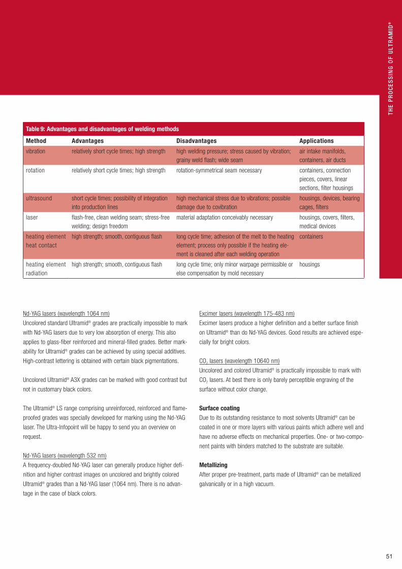
51
THE
Pr
Oc
ESS
inG
OF
UlT
rA
Mid
®
Nd-YAG lasers (wavelength 1064 nm)
Uncolored standard Ultramid® grades are practically impossible to mark
with Nd-YAG lasers due to very low absorption of energy. This also
applies to glass-fiber reinforced and mineral-filled grades. Better mark-
ability for Ultramid® grades can be achieved by using special additives.
High-contrast lettering is obtained with certain black pigmentations.
Uncolored Ultramid® A3X grades can be marked with good contrast but
not in customary black colors.
The Ultramid® LS range comprising unreinforced, reinforced and flame-
proofed grades was specially developed for marking using the Nd-YAG
laser. The Ultra-Infopoint will be happy to send you an overview on
request.
Nd-YAG lasers (wavelength 532 nm)
A frequency-doubled Nd-YAG laser can generally produce higher defi-
nition and higher contrast images on uncolored and brightly colored
Ultramid® grades than a Nd-YAG laser (1064 nm). There is no advan-
tage in the case of black colors.
Excimer lasers (wavelength 175-483 nm)
Excimer lasers produce a higher definition and a better surface finish
on Ultramid® than do Nd-YAG devices. Good results are achieved espe-
cially for bright colors.
CO2 lasers (wavelength 10640 nm)
Uncolored and colored Ultramid® is practically impossible to mark with
CO2 lasers. At best there is only barely perceptible engraving of the
surface without color change.
Surface coatingDue to its outstanding resistance to most solvents Ultramid® can be
coated in one or more layers with various paints which adhere well and
have no adverse effects on mechanical properties. One- or two-compo-
nent paints with binders matched to the substrate are suitable.
MetallizingAfter proper pre-treatment, parts made of Ultramid® can be metallized
galvanically or in a high vacuum.
Table 9: Advantages and disadvantages of welding methods
Method Advantages Disadvantages Applications
vibration relatively short cycle times; high strength high welding pressure; stress caused by vibration; grainy weld flash; wide seam
air intake manifolds, containers, air ducts
rotation relatively short cycle times; high strength rotation-symmetrical seam necessary containers, connection pieces, covers, linear sections, filter housings
ultrasound short cycle times; possibility of integration into production lines
high mechanical stress due to vibrations; possible damage due to covibration
housings, devices, bearing cages, filters
laser flash-free, clean welding seam; stress-free welding; design freedom
material adaptation conceivably necessary housings, covers, filters, medical devices
heating element heat contact
high strength; smooth, contiguous flash long cycle time; adhesion of the melt to the heating element; process only possible if the heating ele-ment is cleaned after each welding operation
containers
heating element radiation
high strength; smooth, contiguous flash long cycle time; only minor warpage permissible or else compensation by mold necessary
housings

52
The processing of Ultramid®
Conditioning
Ultramid® parts, especially those made from standard injection-mold-
ing grades, only achieve their optimum impact strength and constant
dimensions after absorption of moisture. Conditioning, i. e. immersion
in warm water or storage in warm, moist air is used for the rapid
attainment of a moisture content of 1.5 to 3 %, the equilibrium content
in normal moist air (cf. Fig. 23, p. 23 and individual values in the
Ultramid® range chart).
Practical conditioning methodImmersion in warm water at 40 °C to 90 °C is simple to carry out but
it can result in water stains, deposits and, especially in the case of
thin parts with internal stresses, in warpage. Additionally, in the case
of the reinforced grades the quality of the surface can be impaired.
Furthermore, conditioning of A3X grades in a waterbath at higher
temperatures is not recommended. Accordingly, preference is generally
given to the milder method of conditioning in humid air (e. g. at 40 °C
and 90 % relative humidity or in 70 / 62 conditions for the accelerated
conditioning of test specimens in accordance with ISO 1110). Here too
the temperature should not exceed about 40 °C for parts made from
Ultramid® A3X.
As a simple method of conditioning, parts can also be stored in the
warm in PE sacks containing 5 to 10 % of water with respect to the
weight of the parts.
Duration of conditioningThe time required for conditioning to the normal moisture content
(standard conditions 23 / 50) increases with the square of the wall
thickness of the parts but decreases markedly with rising temperature.
Table 10 gives the conditioning times needed for flat parts (sheet)
made from Ultramid® A and B grades as a function of wall thickness
and conditioning conditions in either a moist atmosphere or in a water-
bath. Conditioning in a moist atmosphere, e.g. 40 °C / 90 % r.h., is
generally recommended as a mild thermal treatment.
Our Technical Information leaflet “Conditioning Ultramid® moldings”
provides further details.
Annealing
Annealing, e. g. by heat treatment for 12 to 24 hours (ideally in an anneal-
ing liquid at 140 °C to 170 °C) can largely remove internal stresses
occurring in thick-walled parts made from grades with a high modulus
of elasticity (e. g. Ultramid® A3EG7) or in extruded semi-finished parts.
Annealing also results in postcrystallization of incompletely crystallized
injection-molded parts (produced with a cold mold). On the one hand
this causes an increase in density, abrasion resistance, rigidity and
hardness and on the other hand it gives rise to slight after-shrinkage
and sometimes a small amount of warpage.
Heat-resistant mineral, paraffin and silicone oils are excellent annealing
liquids. The annealed parts must be cooled slowly.

53
THE
Pr
Oc
ESS
inG
OF
UlT
rA
Mid
®
Table 10: Time required for Ultramid® sheet to attain a moisture content corresponding to the equilibrium moisture content obtained in a standerd atmosphere (23ºC / 50 % r. h.)1 (figures in bold type refer to days, non-bold to hours)
Ultramid® Equilibrium moisture content atmosphere
Conditions Thickness [mm]
NK 23 / 50 [%]1 1 2 4 6 8 10
B-grades unreinforced glass-fiber reinforced mineral-filled
3.0
1.5…2.6 2.0…2.4
Water bath 40 °C 60 °C 80 °C
3.5 1
0,3
14 4 1
2.5 16 4
5 1.5 10
10 3 18
16 4.5 1
Atmosphere 40 °C / 90 % 70 °C / 62 %2
15 10
2.5 2
11 5
25 10
45 70
A-grades unreinforced glass-fiber reinforced mineral-filled
2.8
1.2…2.2 1.4…1.5
Water bath 40 °C 60 °C 80 °C
6 1.5 0.5
1.3 6 2
4.5 1 8
10 2.5 20
20 5
1.5
28 8
2.5
Atmosphere 40 °C / 90 % 70 °C / 62 %2
1 15
4 2.5
18 10
40 23
70
1 Values for individual grades are given in the Ultramid® range chart.2 Used in ISO 1110- Polyamides- Accelerated conditioning of test specimens.
Fan rotorAir intake channel

54
Safety notes
Safety precautions during processingUltramid® melts are thermally stable at the usual temperature for A, B
and C of ≤ 310 °C and ≤ 350 °C for T and do not give rise to hazards
due to molecular degradation or the evolution of gases and vapors.
Like all thermoplastic polymers, Ultramid® decomposes on exposure
to excessive thermal load, e. g. when it is overheated or as a result of
cleaning by burning off. In such cases gaseous decomposition products
are formed. Decomposition accelerates above the usual temperatures,
the initial products formed being mainly carbon monoxide and ammo-
nia, and caprolactam in the case of Ultramid® B. At temperatures above
about 350 °C (Ultramid® T above 400 °C ) small quantities of pungent
smelling vapors of aldehydes, amines and other nitrogenous decompo-
sition products are also formed.
When Ultramid® is properly processed no harmful vapors are produced
in the area of the processing machinery.
In the event of incorrect processing, e. g. high thermal stresses and / or
long residence times in the processing machine, there is the risk of
elimination of pungent-smelling vapors which can be a hazard to health.
Such a failure additionally becomes apparent due to brownish burn
marks on the moldings. This is remedied by ejection of the machine
contents into the open air and reducing the cylinder temperature at the
same time. Rapid cooling of the damaged material, e. g. in a waterbath,
reduces nuisances caused by odors.
In general measures should be taken to ensure ventilation and venting
of the work area, preferably by means of an extraction hood over the
cylinder unit.
General information
Food contact statusSome standard-grades of the Ultramid® product line are in conformity
with the current regulations for food contact in Europe and USA with
respect to their composition. In addition the Recommendations of
the German BfR (The governmental institute for risk assessment =
Bundesinstitut für Riskobewertung, former BgV V/BGA ) are fulfilled.
The Ultramid® grades labelled with W, H, U and X (second letter in the
trade mark) are not suitable for food contact applications.
In case of detailed information about the food contact status for
an Ultramid® grade please contact BASF Aktiengesellschaft
([email protected]) directly. We are pleased to send you
a food contact compliance letter with respect to the regulations
in force at present.
Quality management
Quality management is an integral part of BASF’s corporate policy.
Customer satisfaction with the products and services offered by BASF
is an essential objective of this policy.
The Engineering Plastics Business Unit Europe of BASF AG has a
process-oriented quality management system that has been certified
according to ISO / TS 16949 by an accredited certifying agency. This
certification encompasses all services rendered in conjunction with the
development, production, marketing and sale of ultraplastics.
The business unit ensures the proper functionality and further develop-
ment of the quality management system by constantly improving its
procedures, processes and products.
FSi intake manifold system

55
GEn
ErA
l in
FOr
MA
TiO
n
Quality assurance
Goods inward inspection at the converterIn most countries converters have a legal duty to carry out goods
inward inspections. Such inspections are also essential because it
is only in this way that the converter can obtain reliable knowledge
as to the state of the goods at the time of their arrival.
Apart from a visual examination, depending on the product and
requirements a goods inward inspection for Ultramid® primarily
covers the set of test methods set out in Table 17. Many other test
methods suitable for Ultramid® are presented in DIN 16773, Part 2,
or ISO 1874-2 “Polyamide molding compounds for injection-molding
and extrusion”.
The values obtained from these test methods for the various Ultramid®
grades are given in the Ultramid® range chart.
Quality assurance in the converting plantQuality assurance is a component of every modern injection-mold-
ing operation because apart from effects arising from the product the
quality of Ultramid® moldings is primarily determined by the processing
parameters. Unchanging processing conditions are the prerequisite for
obtaining injection-molded parts of consistent quality. The most impor-
tant process parameters are:
Melt temperature
Mold filling speed
Holding pressure and time
Mold surface temperature
Modern injection-molding machines are fitted with process regulation
instruments with which the defined variables can be kept constant
within a narrow tolerance range. Narrower process tolerances during
processing generally give rise to injection-molded parts having a uni-
form quality. Quality assurance can be facilitated through documenta-
tion of the actual values.
Table 11: Test methods for goods inward inspection of Ultramid®
Test method1 Typical value given in Ultramid® range chart
Test standards
Remarks
Identification DIN 53746 Simple methods of indentification by means of melting point, density, solubility
Melting point • ISO 3146 -C ISO 3146 -A
DSC technique (heating and cooling rates 20 °C /min) Capillary tube method
Density • ISO 1183 BASF simplified density titration method
Ash •2 ISO 3451-4 To determine the content of reinforcing material
Viscosity number VZ • ISO 307 Solvent 96 % H2SO4, in the case of reinforced and modified products, a correction must be made to the amount weighed out
Melt volume rate MVR
• ISO 1133 Preferred test conditons: 275 °C / 5 kg load (Ultramid® T 325 °C / 5 kg); material must contain less than 0.05 % water
Moisture content •3 ISO 960 D Vapor Pressure method (BASF) Computer controlled coulometric Karl Fischer titrator; fine determiation in microgram range possible (Mitsubishi method)
1 All tests can be performed on the molding compound or on the molded part.2 Nominal values for the amount reinforcing material are given in the range chart.3 Ultramid® is supplied ready for processing with moisture content of less than 0.15% (injection-molding ) or 0.1% (extrusion)

56
Important quality criteria for Ultramid® moldings are:
Dimensional stability (freedom from warpage)
Surface finish
A simple test on finished parts is to weigh them. Any inconstancy in a
process can generally be observed through weight fluctuations. Surface
finish is checked by visual examination.
Examples of typical surface faults include discoloration, flow lines,
streaks, marks, grooves, sink marks, glass-fiber effects and warps.
A light-microscopic image showing the structure of thin layers of injec-
tion-molded parts is an important quality criterion, especially in the
case of the non-reinforced grades. It serves to depict defective crystal-
line structures and other irregularities inside the parts. Consequently,
the quality of Ultramid® molded parts can be assessed so that conceiv-
able causes for flaws can be ascertained (see Figure 57).
Examination of the microstructure is also useful for determining the
optimum processing conditions. It can also form part of continuous
quality assurance procedures. Planned quality control tasks while
production is in progress are essential for obtaining high-quality engi-
neering parts from Ultramid®. They can be carried out by means of
sampling or if need be done on all parts. Computer assisted test devic-
es reduce the workload for measurements and facilitate documentation
of the tests.
General information
delivery and storage
Ultramid® is supplied in the form of cylindrical or lenticular granules.
The bulk density is approximately 0.7 g /cm³. The products are dried so
as to be ready for processing and they are delivered in moisture-tight
packaging. The standard types of packaging are 25-kg special bags
and 1000-kg bulk-product containers (octagon IBC = intermediate
bulk container made of corrugated cardboard with a liner bag). Upon
consultation, other kinds of packaging and shipment in silo trucks or
railway cars are likewise possible. All packaging is tightly sealed and
should only be opened immediately prior to the processing. The materi-
al, which is delivered completely dry, should not be permitted to absorb
any moisture from the air, so that all packaging has to be stored in dry
rooms and must always be carefully sealed again after any portions
have been removed.
When Ultramid® is kept in undamaged packaging bags, it can be
stored indefinitely. Experience has shown that the product delivered in
an IBC can be stored for approximately three months without the pro-
cessing properties being impaired by moisture absorption. Packaging
stored in cold areas should be allowed to warm up to room tempera-
ture before being opened so that no condensation can precipitate onto
the granules.
Changes in crystalstructure due to themolding and settingprocess
Changes in crystalstructure due to the molding and settingprocess
Flaws in the material
Exernal effects on thefinished part tooverstressing
Detection of flaws causedby finishing process
Fig. 57: Assessment criteria for optical microscopic examination
of finished parts made from Ultramid®

57
GEn
ErA
l in
FOr
MA
TiO
n
Colors
Ultramid® is supplied in both uncolored and colored forms. Uncolored
Ultramid® has a natural opaque white color. Individual grades are avail-
able in several standard colors and shades.
The H and W stabilized Ultramid® grades are exceptions which can only
be supplied in black or natural because their natural color does not
permit colored pigmentation to a specific shade. This is also the case
for Ultramid® A3X grades with fire resistant additive and Ultramid® T
(cf. colors in the Ultramid® range chart).
Ultramid® and the environment
Storage and transportationUnder normal conditions Ultramid® can be stored indefinitely. Even
at elevated temperatures, e. g. 40 °C in air, and under the action of
sunlight and weather no decomposition reactions occur (cf. sections
“Delivery and storage” and “Behavior on exposure to weather”).
Ultramid® is not a hazardous material as defined by the German ordi-
nance on hazardous materials of September 19, 1994 and hence is
not a hazardous material for transportation (cf. Ultramid® safety data
sheet).
Ultramid® is assigned to the German water pollution class WGK 0,
i. e. Ultramid® poses no risk to groundwater.
Waste disposalSubject to local authority regulations Ultramid® can be dumped or
incinerated together with household garbage. The calorific value of
unreinforced grades amounts to 29.000 to 32.000 kJ / kg (Hu accord-
ing to DIN 51900).
lower Bumper Stiffener

58
General information
The burning behavior of Ultramid® is described in detail in the section
“Fire behavior”.
When Ultramid® is completely burned, it releases carbon dioxide,
water and nitrogen oxide. In case of incomplete combustion, carbon
monoxide and hydrogen cyanide are also generated. In addition, the
fire gases contain traces of unburned primary decomposition products
such as, for instance, hydrocarbons, compounds containing nitrogen
and their oxidation products.
The toxicity of the combustion gases is determined primarily by their
carbon monoxide content. Toxicological studies have shown that the
decomposition products given off in the temperature range up to 400 °C
are less toxic than those produced by wood. At higher temperatures
the toxicity is comparable.
RecoveryLike other production wastes, sorted Ultramid® waste materials, e. g.
ground up injection-molded parts and the like, can be fed back to
a certain extent into processing depending on the grade and the
demands placed on it (cf. “Reprocessing and recovering of scrap”).
In order to produce defect-free injection-molded parts containing
regenerated material the ground material must be clean and dry (dry-
ing is usually necessary, cf. “General notes on processing: Preliminary
treatment, drying”). It is also essential that no thermal degradation
has occurred in the preceding processing. The maximum permissible
amount of regrind that can be added should be determined in trials. It
depends on the grade of Ultramid®, the type of injection-molded part
and on the requirements. The properties of the parts, e. g. impact and
mechanical strength, and also processing behavior, such as flow prop-
erties, shrinkage and surface finish, can be markedly affected in some
grades by even small amounts of reground material.
Services
Our customers are constantly seeking ways of optimizing their pro-
cesses. Since the material and the processing machines account
for up to 80 % of the costs of producing a plastic part these are key
factors for success. We help to optimize process parameters and the
use of materials and hence to bring down the production costs to the
lowest level possible.
Major elements of our range of services are computer-aided testing
and optimization of parts together with damage analysis. Our many
years of experience coupled with the latest test methods ensure a sig-
nificant contribution to the speedy solution of your particular problems.
We will be happy to give you more detailed information at our Ultra-
Infopoint.
Circuit carrier from Kromberg & Schubert

59
GEn
ErA
l in
FOr
MA
TiO
n
product range
Injection-molding grades (unreinforced)
Characteristics Ultramid® B Ultramid® A Ultramid® T Ultramid® CCopolyamide
easy flowing, very fast processing, high impact strength once conditioned
B3S
easy flowing to medium viskosity, fast processing, high impact strength, even at dry state
A3K A4K
impact-modified to give very high impact strength even at dry state and low temperatures; fast processing
B3L A3Z
high resistance to heat aging A3W A4H
very high resistance to distortion and heat aging T KR 4350
flame-retardant (UL 94 V-0) C3U
dry-running material with improved tribological properties for unlubricated systems
A3R
Injection-molding grades (reinforced)
Characteristics glass-fiber reinforced (10 % to 50 %)
Ultramid® B Ultramid® A Ultramid® T Ultramid® CCopolyamide
high-impact grades good heat-aging resistance and dielectric properties
B35EG3, B3EG3…6 B3G8
A3EG5…10
impact-modified to give enhanced notched impact strength and breaking strength
B3ZG3 B3ZG6 B3ZG8
T KR 4357 G6
very high heat-aging resistance even in lubricants A3HG5…10
very high heat-aging resistance B3WG5…10 A3WG3…10
with enhanced hydrolysis resistance A3HG6HR
very high resistance to distortion and heat aging T KR 4355 G5 T KR 4355 G7
flame-retardant B3UG4 A3X2G5…10 T KR 4365 G5 C3UG4
mineral-filled (15 % to 40 %)
grades with very high rigidity and strength; low warpage B3WM602
grades with medium rigidity and strength; low warpage B3M6
flame-retardant B3UM4
glass-fiber and mineral-filled; glass-bead reinforced
grades with medium rigidity and strength; low warpage B3WGM24 BG40GM45HS B3GK24
A3WGM53

60
Ultramid® nomenclature
Ultramid® commercial grades are uniformly designated by letters and
digits which indicate chemical composition, melt viscosity, stabilization,
glass fiber content and processing behavior.
1st letterType of PA
B = PA 6
A = PA 66
C = copolyamide 66/6 (melting point 243 °C)
T = copolyamide 6/6T (melting point 298 °C)
KR = special order products
1st digitViscosity class
3 = easy flowing, low melt viscosity, mainly for injection-molding
(however Ultramid® B3 without additives and reinforcement
only for extrusion),
35 = Low to medium viscosity, for injection-molding and for
extruding monofilaments and films
4 = medium viscosity, for injection-molding and extrusion
2nd or 2nd and 3rd letterType of stabilization
E, K = stabilized, light natural color, enhanced resistance to heat
aging, weather and hot water, dielectric properties remain
unaffected (see Table 2)
H = stabilized enhanced resistance to heat aging, weather and hot
water, only for enineering parts,electrical properties remain
unaffected, natural color (see Table 2)
W = stabilized, high resistance to heat aging, only available
uncolored and black, less suitable if high demands are placed
on the part’s electrical properties (see Table 2)
General information
Special properties, additives
HR = enhanced hydrolysis resistance
L = impact-modified and stabilized, impact resistent when dry,
easy flowing, for fast processing
R = PE-modified and stabilized, for highly stressed, low noise,
low-friction bearings
S = for rapid processing, very fine crystalline structure;
for injection-molding
U = with fire-retardant finish without red phosphorus
X2 = with red phosphorus as the fire-retardant finish
Z = impact modified and stabilized with very high low-temperature
impact strength (unreinforced grades) or enhanced impact
strength (reinforced grades)
Type of reinforcement
G (plus digit) = glass-fiber reinforced
C (plus digit) = carbon-glass fiber reinforced
K (plus digit) = glass-bead reinforced, stabilized
M (plus digit) = mineral-filled, stabilized; special product:
M602 with 30 % special-silicate
(enhanced rididity)
Combinations available with glass-fiber reinforcement:
GM (glass fibers /mineral)
GK (glass fibers /glass-beads)
2nd or 2nd and 3rd digitContent of reinforcing material
(mass fraction)
2 = 10 %
3 = 15 %
4 = 20 %
5 = 25 %
6 = 30 %
7 = 35 %
8 = 40 %
10 = 50 %
The amount of reinforcing materials for combinations of glass-fibers
(G), with mineral (M) or glass-beads (K) indicated by 2 digits, e. g.:
GM 53 = 25 % glass-fibers and 15 % mineral, stabilized
GK 24 = 10 % glas-fibers and 20 % glass-beads, stabilized
additives
G
2nd and 3rd letter
3
1st digit
B E 6
1st letter
2nd or

61
GEn
ErA
l in
FOr
MA
TiO
n
Subject index
Aftershrinkage 44, 48Air intake channel 53Annealing 52Application of heat 20Automotive sector 4, 5Awning plug 9
Back pressure 40Barrier screws 34Behavior– on application of heat 20– under cyclic loads 16– on exposure to high-energy radiation 28– on exposure to weather 28– under flexural fatigue strength 16– under long-term static loading 16
Cavitation 18Change of materials 32Characteristics 10Chemical engineering 6Circuit breaker 6Circuit carrier 58Circular connector 14Coefficient of sliding friction 19Colors 57Compatibility 32Conditioning 52, 53Coolant throughput 8Cylinder temperatures 38
Delivery 56Demolding 44Dimensional changes 48Dimensional stability 22Draft 36Drop erosion 18Drying 32Duration of conditioning 52
Effect of– gate position and type 48 – holding pressure 46– injection rate 46– melt temperature 46– mold temperature 46– wall thickness 48Electric and electronic industry 6, 7Electric power steering with plastic worm wheel 33
Example 1Ultramid® A4 H
A = PA 66
4 = viscosity class 4 (medium viscosity)
H = enhanced heat stabilization
Example 2Ultramid® A3X2G10
A = PA 66
3 = viscosity class 3 (low viscosity, for
injection-molding)
X2 = flame retardant (contains phosphorus)
G10 = 50 % fiberglass
Electrical properties 24Engine cover 5Enthalpy 31Environment 57Equilibrium moisture content 25, 53Exposure to weather 28
Fan rotor 53Feeding 40Fire behavior– General notes 26– Tests 26Fixing caps 27Flexural fatigue strength 16 -18Flexural strength 22Flow characteristics 42, 43Food contact status 54Fracture energy W50 15Free shrinkage 45Fuse box 45
Gate position 48Generator end cap 5Glass-fiber reinforced Ultramid® 11, 17, 18, 25Goods inward inspection at the converter 55
Hammer drill 21Heat aging resistance 20, 21– in hot lubricants, coolants and solvents 22High-energy radiation 28, 29Holding pressure 46Hot embossing 50Household 8Housing 8, 42
Impact strength 14, 15, 22Impeded shrinkage 45, 48, 49Injection mold 36Injection molding 34– gas-assisted (GAM) 34– with the water-injection technique (WIT ) 34Injection rate 46Inserts 38Intake manifold system 54Isochronous stress-strain curves 17
Jet erosion 18Joining methods 50

62
General information
Printing 50Processing 30 f f.Processing by injection molding 38, 41Processing characteristics 30, 40Processing temperatures 38, 39Product range 10, 14, 59Properties 10 f f.Protection against abrasion and wear 36
Quality assurance 55 f.Quality assurance in the converting plant 55Quality criteria 56Quality management 54
Recovering of scrap 33Recovery 58Reprocessing 33Residence time 39 f.Resistance to chemicals 27
Safety notes 54Safety precautions during processing 54Sanitary engineering 8, 9Sanitary set (Hewi) 9Screw flight depths 35Screw gate dimensioning 37Screw speed 40Screw tip 35Seat 5Self-coloring 32Services 58Shear modulus 12, 13Shrinkage 44 - 49Shutdown 32Snowboard binding 49Specific volume resistivity 25Spiral flow length 42, 43Stabilized grades 21Start-up 32Storage 56, 57Stress-strain diagrams 15Surface coating 51
Tensile stress 12Tension pulleys 20Terminal block 7Test box 44Test methods for goods inward inspection 55Thermal properties 18, 30Thermostability of the melts 30Three section-screws 34, 35Transportation 26, 57Tribological properties 18Truck-engine sump 19Types of gating 37, 48
Ultramid® grades 10
Vented screws 34Viscometric data 29Viscosity 30, 31Volume resistivity 25
Wall thickness 48Warpage 49Waste disposal 57Water absorption 22, 23Wear due to sliding friction 18Wear rates 19Welding methods 51
Yield stress 11, 12
Laser marking 50Linear expansion 19Low-temperature impact strength 14Lower Bumper Stiffener 5, 28, 57
Machine nozzle 36Machining 50Materials-handling technology 6Measuring stick 9Mechanical engineering 6Mechanical properties 12Melt temperatures 38, 46Melt viscosity 30Melting and setting behavior 30Metallizing 51Mineral-filled Ultramid® 11Modulus of elasticity 11, 13Moisture content 12, 24Mold design 36Mold filling 42Mold temperature control channels and devices 38Mold temperatures 38, 46Mold venting 37 Molding shrinkage 39Molecular data 29
Nd-YAG lasers 51Needle shut-off nozzle 37Nomenclature 60Non-return valve 35
Online paintable car parts
Plasticizing unit 34Plug connector 6, 12Plug-in connector 7, 43Plumbing engineering 8 f.Power engineering 6Practical conditioning method 52Precision engineering 6Preliminary treatment 32

63
GEn
ErA
l in
FOr
MA
TiO
n
Autofroth®* Polyurethane system PU
Basotect ® Foam from melamine resin MF
Capron® Polyamide PA
Cellasto®* Components made from microcellular PU elastomers PU
CeoDS®* Multifunctional composits made from Cellasto components PU
Colorflexx ® Service for the self-coloring of polystyrene and ABS
CosyPUR®* PU soft foam system PU
Ecoflex ® Biodegradable plastic /polyester
Ecovio® Biodegradable plastic /polyester on the basis of renewable raw materials
Elastan®* Systems for sports field surfaces PU
Elastoclear ®* PU system PU
Elastocoat ®* PU systems as coating and casting compounds PU
Elastocoast ®* PU systems as coating and casting compounds PU
Elastocore®* PU cast system PU
Elastoflex ®* Soft polyurethane foam systems PU
Elastofoam®* Soft integral polyurethane foam systems PU
Elastollan®* Thermoplastic polyurethane elastomers PU
Elastolit ®* Rigid integral polyurethane foam systems and RIM systems PU
Elastonat ®* Flexible integral polyurethane systems PU
Elastopan®* Polyurethane shoe foam systems PU
Elastopir ®* Rigid polyurethane foam systems PU
Elastopor ®* Rigid polyurethane foam systems PU
Elastoskin®* Flexible integral polyurethane systems PU
Elastospray ®* PU spray foam system PU
Elasturan®* Systems as cold curing cast elastomers PU
Lupranat ®* Diisocyanates PU
Lupranol®* Polyether polyols PU
Lupranol®*Balance Polyether polyols PU
Lupraphen®* Polyether polyols PU
Luran® Styrene /acrylonitrile copolymer SAN
Luran® S Acrylonitrile /styrene /acrylate polymer ASA
Luran® SC Acrylonitrile /styrene /acrylate polymer and polycarbonate ASA + PC
Miramid® Polyamide PA 6, PA 66
Neopolen® E Polyethylene foam EPE
Neopolen® P Polypropylene foam EPP
Neopor ® Expandable polystyrene PS-E
Palusol® Alkali silicate
PERMASKIN® System for coating components
Peripor ® Expandable polystyrene PS-E
PlasticsPortalTM Web-based e-Commerce platform for solutions and information
Pluracol®** Polyether polyols PU
Polystyrol, impact-modified Polystyrene HIPS PS-I
Polystyrol, standard Polystyrene GPPS PS
SPSTM* Steel-polyurethane systems PU
Styrodur ® C Extruded rigid polystyrene foam XPS
Styroflex ® Styrene / butadiene block copolymer SB
Styrolux ® Styrene / butadiene block copolymer SB
Styropor ® Expandable polystyrene PS-E
Terblend® N Acrylonitrile / butadiene /styrene polymer and polyamide ABS + PA
Terluran® Acrylonitrile / butadiene /styrene polymer ABS
Terluran® HH Acrylonitrile / butadiene /styrene polymer ABS
Terlux ® Methyl methacrylate /acrylonitrile / butadiene /styrene polymer MABS
Ultradur ® Polybutylene terephthalate PBT, (PBT+ ASA)
Ultraform® Polyoxymethylene POM
Ultramid® Polyamide PA 6, 66, 6 / 66, 6 / 6T
Ultrason® E Polyethersulfone PESU
Ultrason® S Polysulfone PSU
Plastics from BASFThe product range at a glance
NoteThe data contained in this publication
are based on our current knowledge and
experience. In view of the many factors
that may affect processing and application
of our product, these data do not relieve
processor from carrying out own inves-
tigations and tests neither do these data
imply any guarantee for certain properties
nor the suitability of the product for a spe-
cific purpose. Any descriptions, drawings,
photographies, data, proportions, weights
etc. given herein may change without
prior information and does not constitute
the agreed contractual quality of the prod-
uct. It is the responsibility of the recipient
of our products to ensure that any propri-
etary rights and existing laws and legisla-
tion are observed. (September 2007)
Please visit our websites:
BASF Plastics:www.plasticsportal.com (World)
www.plasticsportal.eu (Europe)
Additional information on specific products:www.plasticsportal.eu/name of product
e. g. www.plasticsportal.eu/ultramid
Polyurethanes:www.basf.com/polyurethanes
www.elastogran.de
PVC and PVCD:www.solvinpvc.com
® = reg. trademark of BASF Aktiengesellschaft®* =reg.trademarkofElastogranGmbH®**=reg.trademarkofBASFCorporation
TM = trademark of BASF AktiengesellschaftTM*=trademarkofElastogranGmbH

® =
regi
ster
ed tr
adem
ark
of B
ASF
Aktie
nges
ells
chaf
t
Tel.: +49 621 60-78780Fax: +49 621 60-78730
E-Mail: [email protected]
Request of brochures:KS / KC, E 100
Fax: + 49 621 60 - 49497 KTEM
070
5 BE