ultrasonic i
TRANSCRIPT

8/10/2019 Ultrasonic i
http://slidepdf.com/reader/full/ultrasonic-i 1/276/1
Contents 6 - Ultrasonic sensors
OsiSense XX
Selection gu ide . . . . . . . . . . . . . . . . . . . . . . . . . . . . . . . . . . . . . . . . . . . . . page 6/2
General . . . . . . . . . . . . . . . . . . . . . . . . . . . . . . . . . . . . . . . . . . . . . . . . . . page 6/4
Sensors with solid-state digital output
Cylindrical type . . . . . . . . . . . . . . . . . . . . . . . . . . . . . . . . . . . . . . . . . page 6/10
Flat form . . . . . . . . . . . . . . . . . . . . . . . . . . . . . . . . . . . . . . . . . . . . . . . page 6/16
Sensors with analogue output
Cylindrical type and flat form . . . . . . . . . . . . . . . . . . . . . . . . . . . . . . . page 6/20
Sensors for monitoring 2 levels
Cylindrical type . . . . . . . . . . . . . . . . . . . . . . . . . . . . . . . . . . . . . . . . . . page 6/24
b
b
v
v
b
v
b
v
1
2
3
4
5
6
7
8
9
10
1
2
3
4
5
6
7
8
9
10
1
2
3
4
5
6
7
8
9
10

8/10/2019 Ultrasonic i
http://slidepdf.com/reader/full/ultrasonic-i 2/276/2
4
App licati onsDetection of any obj ect without phys ical contact,irrespective of: material (metal, plastic, woo d, cardboard,
etc.), nature (solid, liqu id, powder, etc.), colour, degree oftransparency, etc.
Sensors wi th solid-state digital outputCylindrical type
Dimensions (mm) Ø 12 Ø 18
Sensing distance Sn 5 cm 10 cm 15 cm 50 cm(adjustable)
Assured operat ing d istance(mm)
6.4...51 fixed 6.4...102 fixed 25...152 fixed Adjustable using teach mode
Type of o utput PNP/NPN NPNor PNP
PNP/NPN NPN or PNP
Degree of protection IP 67 IP 67 IP 67 IP 67
Function NO NO NO NO
Connection M8 connector M8 connector M12 connector M12 connector or pre-cabled
Power supply c 12...24 V with protection against reverse polarity
Sensor type XX5 12A1p XX5 12A2p XX5 18A1p XX5 18A3p
XX5 18A3ppL2
Pages 6/10
Sensors with analogue outputCylindrical type
Dimensions (mm) Ø 18 Ø 30
Sensing distance Sn 50 cm (adjustable) 1 m (adjustable)
Assured operat ing d istance(mm)
Adjustable using teach mode Adjustable using teach mode
Type of o utput 4-20 mA/0-10 V 4-20 mA/0-10 V
Degree of protection IP 67 IP 65
Connection M12 connector M12 connector
Power supply c 12...24 V with protection against reverse polarity
Sensor type XX9 18A3p XX9 30A1p
XX9 30S1p
Pages 6/20
Selection guide Ultrasonic sensorsOsiSense XX
2
3
4
5
6
7
8
9
0
2
3
4
5
6
7
8
9
0

8/10/2019 Ultrasonic i
http://slidepdf.com/reader/full/ultrasonic-i 3/276/3
4
Cylindrical type Flat format
App lic ation, monito ring 2 levels
Ø 30 Ø 18 Ø 30 7.6 x 19 x 33 16 x 30 x 74 18 x 33 x 60 + Ø 18
1 m(adjustable)
8 m(adjustable)
50 cm 1 m 2 m 10 cm 25 cm 50 cm (adjustable)
Adjustable using teach mode Adjustable using teach mode 6.4...102fixed
51...254 fixed Adjustable using teachmode
PNP/NPNor NPNor PNP
PNP/NPN
NPNor PNP
PNP/NPN PNP/NPN PNP/NPN NPN or PNP NPN or PNP NPN or PNP
IP 65 IP 67 IP 65 IP 67 IP 67 IP 67 IP 67 IP 67 IP 67
NOor NO + NC
NOor NO + NC
NO + NC NO 2 NO 2 NO NO NO NO
M12connector
M12connector
M12connector
M12connector
M12connector
M12connector
Connector onflying lead
M12 connector M12 connector
c 12...24 V with protection against reverse polarity
XX6 30Ap1XX6 30Sp1
XX6 V3A1 XX6 30A3 XX2 18A3p XX2 30A1p XX2 30A2p XX7 F1A2 XX7 K1A2 XX7 V1A1
6/10 6/24 6/16
Flat format
18 x 33 x 60 + Ø 18
1 m (adjustable) 8 m (adjustable) 50 cm (adjustable)
Adjustable using teach mode Adjustable using teach mode
4-20 mA 0-10 V 4-20 mA 0-10 V 4-20 mA 0-10 V
IP 67 IP 65 IP 67
M12 connector M12 connector M12 connector
c 12...24 V with protection against reverse polarity
XX9 V3A1p XX9 30A3p XX9 V1A1p
6/20
1
2
3
4
5
6
7
8
9
10
1
2
3
4
5
6
7
8
9
10

8/10/2019 Ultrasonic i
http://slidepdf.com/reader/full/ultrasonic-i 4/276/4
2
3
4
5
6
7
8
9
0
2
3
4
5
6
7
8
9
0
Ultrasonic sensors 2 OsiSense XX
Quality, standards and cert ifi cations Quality controlThe OsiSense XX ultrasonic sensors are subjected to special precautions in ord er toguarantee their reliability in th e most arduous industri al environments.
Qualification A qualification procedure on the characteristics of OsiSense XX ultrasonic sensors is carriedout in our laboratories.
ProductionThe electrical characteristics, sensing distances at the ambient temperature and operatingtemperatures are 100% verified.Sensors are randomly selected during the course of production and subjected to monitoringtests on all qualified characteristics.
Customer returnsDefective ultrasonic sensors are subjected to systematic analysis and corrective actions areimplemented to eliminate recurrence of the fault.
b
b
b
Conformity to standardsThe OsiSense XX ultrasonic sensors conform to the standards IEC 60947-5-2.Standards and characteristics: refer to pages 6/11, 6/17, 6/21 and 6/25.
Resistance to chemicals in the environmentTo ensure last ing ef ficient operation, it is essential that any chemicals coming into contact withthe ultrasonic sensors will not affect their casing and, in doing so, prevent their reliableoperation.
Due to the materials used, OsiSense XX ultrasonic sensors are very resistant to:
chemical agents:salts, aliphatic and aromatic oils,petroleum, diluted bases and acids.Depending on their nature and concentration, tests should be carried out beforehand for thefollowing chemical agents:alcohols, ketones and phenols.
food industry products:vegetable oils, animal fats,fruit juices,milk proteins, etc.
b
b
Resistance to the environmentIP 65: protection against water jets.Tested in accordance with IEC 60529: the device is subjected to water sprayed from aØ 6.3 mm nozzle, at a flow rate of 12.5 litres/min for 3 min at a distance of 3 m.No deterioration in either operating or insulation characteristics is permitted.
IP 67: protection against the effects of immersion.Tested in accordance with IEC 60529: the sensor is immersed for 30 minutes in 1 m of water.No deterioration in either operating or insulation characteristics is permitted.
b
b
General

8/10/2019 Ultrasonic i
http://slidepdf.com/reader/full/ultrasonic-i 5/276/5
1
2
3
4
5
6
7
8
9
10
1
2
3
4
5
6
7
8
9
10
Ultrasonic sensors 2 OsiSense XX
RecommendationsThe ultrasonic sensors are designed for use in standard industrial applications involvingpresence detection.
Since these sensors do not incorporate a redundant electrical circuit, they are not suitable foruse in safety applications.For safety applications, please refer to our “Safety solutions using Preventa” catalogue.
Principle of ultrasonic detection PresentationUltrasonic sensors enable detection, without contact, of any object irrespective of its:
material (metal, plastic, wood, cardboard, etc.),nature (solid, liquid, powder, etc.),colour,degree of transparency.
They are used in industrial applications for detecting, for example:the position of machine parts,the presence of the windscreen during automobile assembly,the flow of objects on a conveyor system: glass bottles, cardboard packages, cakes, etc.,the level
of different colour paints in pots,of plastic pellets in injection moulding machine feeders.
The ultrasonic sensors are simple to install due to their integral connector and availability ofcabling and fixing accessories.
bbbb
bbbb
--
Operating princip le The principle of ultrasonic detection is based on measuring the time taken between transmission
of an ultrasonic wave (pressure wave) and reception of its echo (return of transmitted wave).
OsiSense XX ultrasonic sensors comprise:1 high voltage generator
2 piezoelectric transducer (transmitter and receiver)3 signal processing stage4 output stage
Excited by the high voltage generator 1, the transducer (transmitter-receiver) 2 generates apulsed ultrasonic wave (200 to 500 kHz depending on the product) which travels through theambient air at the speed of sound. When the wave strikes an object, it reflects (echo) and travelsback towards the transducer. A micro controller 3 analyses the signal received and measures thetime interval between the transmitted signal and the echo. By comparison with the preset ortaught times, it determines and controls the output states 4.The output stage 4 controls a solid-state switch (PNP or NPN transistor) corresponding to a NOcontact (detection of object).
Advantages of ul trasonic detectionNo physical contact with the object to be detected, therefore, no wear and detection possible
of fragile or freshly painted objects, etc.Detection of any material, irrespective of colour, at the same distance, without adjustment orcorrection factor.Teach mode function, by simply pressing a button, for de fining the effective detection zone.Teaching of the minimum and maximum sensing distances (very precise foreground andbackground suppression, ± 6 mm).Very good resistance to industrial environments (robust products entirely encapsulated inresin).Solid-state units: no moving parts in the sensor, therefore, service life independent of thenumber of operating cycles.Various types of outputs to suit requirements:- digital output for level control or detection of any type of object- analogue output for controlling systems that require a signal that is proportional to thedistance at which the object is detected.
b
b
b
b
b
b
1
4
1
4
TargetTarget
General (continued)

8/10/2019 Ultrasonic i
http://slidepdf.com/reader/full/ultrasonic-i 6/27

8/10/2019 Ultrasonic i
http://slidepdf.com/reader/full/ultrasonic-i 7/276/7
1
2
3
4
5
6
7
8
9
10
1
2
3
4
5
6
7
8
9
10
Ultrasonic sensors 2 OsiSense XX
Digital outputs LED indicatorsThe majority of OsiSense XX ultrasonic sensors incorporate light-emitting diode output stateindicators.
Ø 12 sensor, sensitivity 50 mm and 100 mmv Green LED (power on)v Yellow LED (object present).
Ø 18 sensor, sensitivity 500 mmv Yellow LED (object present) and green LED (power on) + user assistance when adjustingthe detection zone.
Ø 30 sensor, sensitivity 1 to 8 mv Multicolour LED for assisting the user when adjusting the detection zonev Yellow LED (object present).
Ø 30 sensor, sensitivity 1 to 8 m with analogue outputv Multicolour LED for assisting the user when adjusting the detection distancev Yellow LED (object present, with luminosity increasing as output signal increases).
Parallelepiped format sensor v
XXp
F: Dual colour yellow (object present) or green (power on) LEDv XXpV: Dual colour yellow (object present) or green (power on) LED + user assistancewhen adjusting the detection zone.v XXpK: Yellow LED (object present); green LED (power on)
b
b
b
b
b
Sensors with digital switching Contact logic output
Normally open (NO)Corresponds to a sensor whose output changes to the closed state when an object is present inthe operating zone.
Normally closed (NC)Corresponds to a sensor whose output changes to the closed state when an object is present inthe operating zone.
b
b
4-wire technique cNO output/PNP and NPN NO + NC output/NPN NO + NC output/PNP
These sensors comprise 2 wires for the supply and 1 wire for each output signal
3-wire technique c
NO output/NPN NO output/PNP
These sensors comprise 2 wires for the supply and 1 wire for the output signal
PNP type: switching the positive side to the loadNPN type: switching the negative side to the load
Sensors with analogue output Operation
The characteristic feature of these sensors is the output which delivers a signal (either current orvoltage) that is proportional to the distance of the object being detected. Within the detectionlimits, which are adjustable using teach mode, the value of the output signal increases as theobject moves away.When an object is detected, an LED indicator (D) illuminates and its luminosity increases inrelation to the value of the output signal. The slope of the signal can simply be changed usingbutton.
Advantages
Visual information available relating to the sensor/object distance.Protection against reverse polarity.Protection against overloads and short-circuits.No residual current, low voltage drop.
bbbb
LED
Outputstate
LED
Outputstate
Objectpresent
NO output
Objectpresent
NC output
LED
Outputstate
LED
Outputstate
Objectpresent
NO output
Objectpresent
NC output
NC contactNO contact NC contactNO contact
+
–
NPN
PNP
NO
NO
+
–
NPN
PNP
NO
NO
+
–
NPN NC
NO
+
–
NPN NC
NO
+
–
PNP NC
NO
+
–
PNP NC
NO
+
–
NPN
+
–
NPN
+
–
PNP
+
–
PNP
10 V / 20 mA
0 V / 4 mA
D
Blind zone
Output
Detection limits (adjustable)
Object
10 V / 20 mA
0 V / 4 mA
D
Blind zone
Output
Detection limits (adjustable)
Object
General (continued)

8/10/2019 Ultrasonic i
http://slidepdf.com/reader/full/ultrasonic-i 8/276/8
2
3
4
5
6
7
8
9
0
2
3
4
5
6
7
8
9
0
Ultrasonic sensors 2 OsiSense XX
Power supply DC sourceCheck that the voltage limits of the sensor and the acceptable level of ripple, are compatible withthe supply used.
AC source (comprising transformer, rectifier, smoothing capacitor)
The supply voltage must be within the operating limits specified for the sensor.
Where the voltage is derived from a single phase AC supply, the voltage must be rectified andsmoothed to ensure that:
the peak voltage of the DC supply is lower than the maximum voltage rating of the sensor.Peak voltage = nominal voltage x 2the minimum voltage of the DC supply is greater than the minimum voltage rating of thesensor, given that:ΔV = (I x t) / CΔV = maximum ripple: 10% (V),I = anticipated load current (mA),t = period of 1 cycle (10 ms full-wave rectified for a 50 Hz supply frequency),C = capacitance (μF).
As a general rule, use a transformer with a lower secondary voltage (Ue) than the requiredDC voltage (U).
Example:a 18 V to obtain c 24 V.
b
b
Setting-up precautions MountingMounting distance between ul trasonic sensors
If 2 standard sensors are mounted too close to each other, the wave transmitted by one sensoris likely to interfere with the other and result in erratic operation.In order to avoid this, it is necessary to adhere to the minimum distances between sensors.
Maximum t ightening torqueCylindricalsensors
Diameter mm
Tighteningtorque
Flat sensors Screw Tighteningtorque
XXp12p Ø 12 0.7 N.m XXpFp M3 0.7 N.m
XXp8p Ø 18 1 N.m XXpKp M4 1 N.m
XXp0p Ø 30 1.35 N.m XXpVp M3 0.7 N.m
XXpV3p – 1.35 N.m Ø 18 1 N.m
Interchangeability
Using the indexed fixing clamp, the assembly is similar to a block type sensor.
CablingElectrical connection
Connect the sensor before switching on the supply
Length of cableNo limitation up to 200 m or up to a line capacitance of < 0.1 μF.It is, however, advisable to take into account the voltage drop on the line.
Separation of con trol and power c ablesThe sensors are immune to electrical interference encountered in normal industrial conditions.Where extreme conditions of electrical “noise” could occur (large motors, spot welders, etc.), itis advisable to protect against transients in the normal way:
suppress interference at source,separate power and control wiring from each other,smooth the supply,limit the length of cable.
b
b
b
----
e
e
ounting side by side u Sn
Mounting face to facee u 4 Sn max.
e
e
ounting side by side u Sn
Mounting face to facee u 4 Sn max.
General (continued)

8/10/2019 Ultrasonic i
http://slidepdf.com/reader/full/ultrasonic-i 9/27

8/10/2019 Ultrasonic i
http://slidepdf.com/reader/full/ultrasonic-i 10/276/10
2
3
4
5
6
7
8
9
0
2
3
4
5
6
7
8
9
0
References
Fixed sensing distance sensorsSen so rs Sens ing
distance
(Sn)
Function Connection Output Reference Weight
m kg
Ø 12 0.05 NO + NO M8 connector PNP/NPN XX5 12A1KAM8 0.011
0.10 NO M8 connector NPN XX5 12A2NAM8 0.011
PNP XX5 12A2PAM8 0.011
Ø 18 0.15 NO + NO M12 connector PNP/NPN XX5 18A1KAM12 0.033
Adjustable sensing distance sensorsØ 18 0.50
(adjustable)NO Pre-cabled
(L = 2 m)NPN XX5 18A3NAL2 0.080
PNP XX5 18A3PAL2 0.080
M12 connector NPN XX5 18A3NAM12 0.033
PNP XX5 18A3PAM12 0.033
Ø 30 1(adjustable)
NO + NO M12 connector PNP/NPN XX6 30A1KAM12 0.090
NO M12 connector NPN XX6 V3A1NAM12 0.090
PNP XX6 V3A1PAM12 0.090
NO + NC M12 connector NPN XX6 30A1NCM12 0.090XX6 30S1NCM12 (1) 0.090
PNP XX6 30A1PCM12 0.090
XX6 30S1PCM12 (1) 0.090
8(adjustable)
NO + NC M12 connector NPN XX6 30A3NCM12 0.110
PNP XX6 30A3PCM12 0.110
(1) Stainless steel 303 case.
AccessoriesTeach pushbutton
Teach pushbutton For use withsensors
Reference Weightkg
Selection of d etection windowInput: M12 female connector Output: M12 male connector
XX5 18A3p AM12and XX6 V3Ap AM12
XXZ PB100 0.035
Cabling accessori es (4-wire output) (2)
Connectors For use withsensor
Type of connection
Reference Weightkg
M8, 3-pin Ø 12 IDC Straight XZ CC8FDM30V 0.010
Elbowed XZ CC8FCM30V 0.010
M8, 4-pin Ø 12 Solder terminals Straight XZ CC8FDM40S 0.010
Elbowed XZ CC8FCM40S 0.010
M12 Ø 18, Ø 30 Screw terminals,metal clampingring
Straight XZ CC12FDM40B 0.020
Elbowed XZ CC12FCM40B 0.020
Screw terminals,plastic clampingring
Straight XZ CC12FDP40B 0.020
Elbowed XZ CC12FCP40B 0.020
Pre-wiredconnectors
For use withsensor
Type Lengthm
Reference Weightkg
M8, 3-pin Ø 12 Straight 2 XZ CP0166L2 (3) 0.080
Elbowed 2 XZ CP0266L2 (3) 0.080
M12 Ø 18, Ø 30 Straight 2 XZ CP1141L2 (3) 0.090
Elbowed 2 XZ CP1241L2 (3) 0.090
Fixing accessories
Description For use withsensor
Reference Weightkg
Fixing clamps Ø 12 XSZ B112 0.006
Ø 18 XSZ B118 0.010
90° fixing bracket Ø 12 XXZ 12 0.025
Ø 18 XUZ A118 0.038
Ø 30 XXZ 30 0.115
3D fixing kit (4) M12 rod Ø 12, Ø 18 and Ø 30 XUZ 2001 0.050
Support for M12rod
Ø 12, Ø 18 and Ø 30 XUZ 2003 0.160
Ball-joint
mounted fixingbracket
Ø 12 XUZ B2012 0.175
Ø 18 XUZ B2003 0.175
Ø 30 XUZ B2030 0.160
(2) For 3-wire cabling accessories, refer to the Global Detection catalogue.(3) For a 5 m long cable replace L2 byL5; for a 10 m long cable replace L2 byL10.(4) To obtain a 3D fixing kit, order:
rod support XUZ 2003, M12 rod XUZ 2001 and ball-joint mounted fixing bracket XUZ B20pp
XX5 12A1KAM8
XZ CC12FDp40B
XZ CP1041Lp
5 6 4 5 4 6
XXZ PB100
5 6 4 5 3 0
5 6 4 5 4 7
XX5 18A1KAM12
XX5 18A3ppL2
5 3 7 6 8 8
XX5 18A3p AM12
5 3 2 7 1 3
5 3 2 2 4 3
XX6 30A1KAM12
5 6 4 5 3 1
XX6 30A3pCM12
5 6 4 5 3 3
5 6 4 5 3 4
5 6 4 5 3 5
5 6 4 5 3 2
XSZ B11p XUZ A118
5 3 2 4 1 7
3D fixing kit example
5 3 7 7 2 7
XX6 V3A1pCM12
XUZ 2003
XUZ 2001 B20XUZ
Ultrasonic sensorsOsiSense XXCylindrical plastic case, M12 x 1, M18 x 1, M30 x 1.5DC supply, solid-state output
General:page 6/4
Characteristics:page 6/10
Dimensions:pages 6/12 and 6/13
Schemes:page 6/15

8/10/2019 Ultrasonic i
http://slidepdf.com/reader/full/ultrasonic-i 11/276/11
1
2
3
4
5
6
7
8
9
10
1
2
3
4
5
6
7
8
9
10
Characteristics,setting-up
Sensor type XX512A1pppp
XX512A2pppp
XX518A1pppp
XX518A3pM12
XX518A3ppL2
XX6V3A1pppp
XX630A1pppp30S1pppp
XX630A3pppp
CharacteristicsProduct certifications e, UL e, UL,
CSAe, UL e, UL, CSA
Conformity to standards IEC 60947-5-2, UL508 pending and CSA C22-2 n° 14 pending
Connection Connector M8, 4-pin M8, 3-pin M12, 4-pin M12, 4-pin – M12, 4-pin M12, 4-pin M12, 4-pin
Pre-cabled – – – – Length = 2 m4 x 0.008mm2
– – –
Sensing range mm 6.4…51 6.4…102 19…152 51…508 51…508 100...1000 51…991 203…8000
Nominal sensingdistance (Sn)
m 0.05 0.1 0.15 0.50 0.50 1 1 8
Detection distance mm Fixed Remotely adjustable using externalteach button
Adjustable using teachbutton on sensor
Blind zone (no object must pass through this zone whilstthe sensor is operating)
mm 0…6.4 0…6.4 0…19 0…51 0…51 0...100 0…51 0…203
Differential travel mm < 0.7 < 0.7 < 0.35 < 2.5 < 2.5 < 2.5 < 2.5 < 12.7Transmission frequency kHz 500 300 300 180 200 75
Repeat accuracy mm ± 0.7 ± 1.27 ± 1.27 ± 1.6 ± 0.9 ± 2.54
Overall beam angle (see detection lobe) 11° 10° 8° 6° 6° 7° 10° 16°
Minimum size of object to be detected Cylinder Ø 2.5 mm orflat bar 1 mm wide
CylinderØ 1.6 mm
CylinderØ 2.5 mmup to asensingdistance of150 mm
CylinderØ 2.5 mm upto a sensingdistance of150 mm
CylinderØ 50 mmup to asensingdistance of1000 mm
CylinderØ 1.6 mmup to asensingdistanceof 635 mm
CylinderØ 50.8 mmup to asensingdistance of4732 mm
Degree of pr otection Conforming to IEC 60529and IEC 60947-5-2
IP 67 IP 67 IP 65 IP 67
Storage temperature °C - 40…+ 80
Operating temperature °C - 20…+ 65 0…+ 50 - 20…+ 65 - 20…+ 65 0…+ 70 0…+ 60 - 20…+ 60
Materials Case ULTEM® Valox® Valox® Valox® ULTEM® ULTEM®
Stainless steel 303 for XX6 30AS1pppp
Sensing face Epoxy Silicone Epoxy Epoxy Epoxy Silicone Epoxy
Vibration resistance Conforming to IEC 60068-2-6 Amplitude ± 1 mm (f = 10…55 Hz)
Mechanical shockresistance
Conforming to IEC 60068-2-27 30 gn, duration 11 ms, in all 3 axes
Resistance to electromagnetic interference
Electrostatic discharges Conforming to IEC 61000-4-2 kV 8, level 4
Radiated electromagneticfields
Conforming to IEC 61000-4-3 V/m 10, level 3
Fast transients Conforming to IEC 61000-4-4 kV 1, level 3
LED indicators Output state YellowLED
YellowLED
– Yellow LED
Power on GreenLED
GreenLED
– Green LED –
Setting-up assistance – – – Dual colour LED Multicolour LED
Rated supply voltage V c 12…24 V with protection against reverse polarity
Voltage limits (including ripple) V c 10…28 V
Current consumption, no-load mA 25 60 40 40 60 50 50
Switching capacity mA < 100 (PNP and NPN) with overload and short-circuit protection
Voltage drop V < 1 (NPN); < 1.5 (PNP)
Maximum switching frequency Hz 125 125 80 40 40 70 10 2
Delays First-up ms 20 20 350 100 100 75 720 800
Response ms 2 3 3 10 10 15 20 200
Recovery ms 2 3 3 10 10 75 20 200
Deviation angle from 90° ofhe object to be detected
± 10° ± 10° ± 10° ± 7° ± 7° ± 5° ± 7° ± 5°
Setting-upMinimum mounting distances
Side by side Face to face
e: respect the distances indicated on thedetection curves shown on page 6/14.
e = 4 x Sn max.
ee
Ultrasonic sensorsOsiSense XXCylindrical plastic case, M12 x 1, M18 x 1, M30 x 1.5DC supply, solid-state output
General:page 6/4
References:page 6/10
Dimensions:pages 6/12 and 6/13
Schemes:page 6/15

8/10/2019 Ultrasonic i
http://slidepdf.com/reader/full/ultrasonic-i 12/276/12
2
3
4
5
6
7
8
9
0
2
3
4
5
6
7
8
9
0
Dimensions
DimensionsXX5 12App AM8
M12x1
50
38
58
XX5 18A1KAM12 XX5 18A3ppL2 XX5 18A3p AM12
6551
M18x1
74
M18x1
63,7
49,5
43,3
4,7
M18x1
77,643,28,9 4,8
M12x1
XX6 30A1ppM12/ XX6 30S1ppM12 XX6 V3A1p AM12 XX6 30A3ppM12
85
95
45 20
M30x1,5 M30x1
95,2
378,9 3,2
M12x1
Ø 2 7 , 2
117,35
42,164,3
M30x1,5
Ø 4 3 , 2
XXZ PB100
63
1614,5
(1) M12x1
2 0
(1) Cable, length: 152.4 mm.
Ultrasonic sensorsOsiSense XXCylindrical plastic case, M12 x 1, M18 x 1, M30 x 1.5DC supply, solid-state output
General:page 6/4
References:page 6/10
Characteristics:page 6/11
Schemes:page 6/15

8/10/2019 Ultrasonic i
http://slidepdf.com/reader/full/ultrasonic-i 13/27

8/10/2019 Ultrasonic i
http://slidepdf.com/reader/full/ultrasonic-i 14/276/14
2
3
4
5
6
7
8
9
0
2
3
4
5
6
7
8
9
0
Curves
Detection curvesXX5 12A1KAM8 XX5 12A2pNAM8 XX5 18A1KAM12
0 10 20 30 40 50 60-20
-10
10
20mm
mm cm2 4 6 8 100
10
-10
20
-20
mm
100 150 200500mm
40
-40
80
-80
mm
XX5 18A3ppL2/XX5 18A3p AM12 XX6 30A1pCM12 XX6 30A3pCM12
65 19 0 32 0 4 45 57 0mm
0
mm
100
-100
200
-200
20 40 60 80 100cm
0
100
200
-100
-200
mm
2 4 6 8 m0
200
-200
400
-400
cm
-100
100
300
-300
XX6 V3A1
20 40 60 80 100cm
0
100
200
-100
-200
mm
Blind zone
Ultrasonic sensorsOsiSense XXCylindrical plastic case, M12 x 1, M18 x 1, M30 x 1.5DC supply, solid-state output
General:page 6/4
References:page 6/10
Characteristics:page 6/11
Dimensions:pages 6/12 and 6/13
Schemes:page 6/15

8/10/2019 Ultrasonic i
http://slidepdf.com/reader/full/ultrasonic-i 15/276/15
1
2
3
4
5
6
7
8
9
10
1
2
3
4
5
6
7
8
9
10
Schemes
Wiring schemesM8 connector
XX5 12A1KAM8 XX5 12A2p
4-wire type NO outputs, PNP and NPN 3-wire type NO outputs, NPN NO outputs, PNP
1 (+) 2 PNP output3 (-) 4 NPN output
(-) BU (Blue) (+) BN (Brown)WH (White) BK (Black)
1 (+) 3 (-)4 NPN or PNP output
(-) BU (Blue) (+) BN (Brown)BK (Black)
M12 connector
XX5 18A1KAM12 XX5 18A3p, XX6 V3p
4-wire type NO outputs, PNP and NPN 3-wire type NO outputs, NPN NO outputs, PNP
1 (+) 2 PNP output3 (-) 4 NPN output
(-) BU (Blue) (+) BN (Brown)WH (White) BK (Black)
1 (+) 2 Teach input3 (-) 4 NPN or PNP output
(-) BU (Blue) (+) BN (Brown)BK (Black)WH (White)
Pre-cabledXX5 18A3ppL2
PNP output NPN output
+
–
BN
BK
BU
WH
XX6 30A1KAM12 XX6 30AppCM124-wire type NO outputs, PNP and NPN NO + NC outputs, NPN NO + NC outputs, PNP
1 (+) 2 PNP output3 (-) 4 NPN output
(-) BU (Blue) (+) BN (Brown)WH (White) BK (Black)
(-) BU (Blue) (+) BN (Brown)WH (White) BK (Black)
Wiring for teaching of detection windowUsing external contactXX5 18A3p/XX6 V3p
Using XXZ PB100
3/BU
1/BN2/WH
4
41
13
3
4
1
3
2
2
4
1
3
Sensor side
M12 maleconnector
M12 femaleconnector
Output XXZ PB100
3/BU
1/BN 1/BN
NO
2/WH
4/BK
3/BU
4/BK
XX5 18A3p /XX6V3p XXZ PB100
4
3
2
1
4
3
2
12/WH
3/BU
4/BK
1/BN
NPN
PNP 2/WH
3/BU
4/BK
1/BN
NPN
PNP
4
1 3
4
1 33/BU
4/BK
1/BN
NPN
3/BU
4/BK
1/BN
NPN
4/BK
3/BU
1/BN
PNP 4/BK
3/BU
1/BN
PNP
3
2
4
1
3
2
4
1
2/WH
3/BU
4/BK
1/BN
NPN
PNP 2/WH
3/BU
4/BK
1/BN
NPN
PNP
3
2
4
1
3
2
4
1
2/WH
3/BU
4/BK
1/BN
NPN
2/WH
3/BU
4/BK
1/BN
NPN
2/WH3/BU
4/BK
1/BN
PNP
2/WH3/BU
4/BK
1/BN
PNP
3
2
4
1
3
2
4
1
2/WH
3/BU
4/BK
1/BN
NPN
PNP 2/WH
3/BU
4/BK
1/BN
NPN
PNP
3/BU
2/WH 4/BK
1/BN
NPNNC
NO
3/BU
2/WH 4/BK
1/BN
NPNNC
NO
3/BU
2/WH
4/BK
1/BN
PNP NC
NO
3/BU
2/WH
4/BK
1/BN
PNP NC
NO
Ultrasonic sensorsOsiSense XXCylindrical plastic case, M12 x 1, M18 x 1, M30 x 1.5DC supply, solid-state output
General:pages 6/4
References:page 6/10
Characteristics:page 6/11
Dimensions:pages 6/12 and 6/13
Schemes:page 6/15
Load
+
–
BN
BK
BU
WH
Load
Teach
Teach
8/10/2019 Ultrasonic i
http://slidepdf.com/reader/full/ultrasonic-i 16/276/16
2
3
4
5
6
7
8
9
0
2
3
4
5
6
7
8
9
0
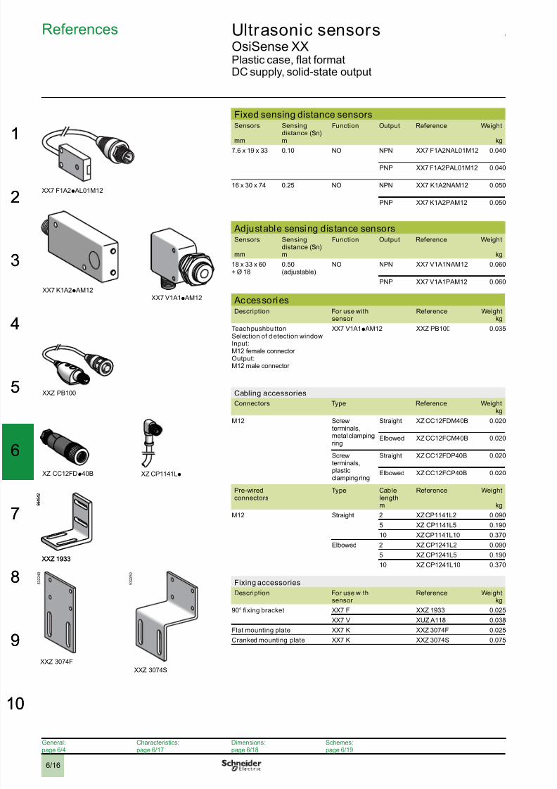
Ultrasonic sensors 2 OsiSense XXPlastic case, flat formatDC supply, solid-state output
Fixed sensing distance sensorsSensors
mm
Sensingdistance (Sn)m
Function Output Reference Weight
kg
7.6 x 19 x 33 0.10 NO NPN XX7 F1A2NAL01M12 0.040
PNP XX7 F1A2PAL01M12 0.040
16 x 30 x 74 0.25 NO NPN XX7 K1A2NAM12 0.050
PNP XX7 K1A2PAM12 0.050
Adjustable sensing distance sensorsSensors
mm
Sensingdistance (Sn)m
Function Output Reference Weight
kg
18 x 33 x 60+ Ø 18
0.50(adjustable)
NO NPN XX7 V1A1NAM12 0.060
PNP XX7 V1A1PAM12 0.060
AccessoriesDescription For use with
sensor Reference Weight
kg
Teach pushbu ttonSelection of d etection windowInput:M12 female connector Output:M12 male connector
XX7 V1A1p AM12 XXZ PB100 0.035
Cabling accessories
Connectors Type Reference Weightkg
M12 Screwterminals,metal clampingring
Straight XZ CC12FDM40B 0.020
Elbowed XZ CC12FCM40B 0.020
Screwterminals,plasticclamping ring
Straight XZ CC12FDP40B 0.020
Elbowed XZ CC12FCP40B 0.020
Pre-wiredconnectors
Type Cablelengthm
Reference Weight
kg
M12 Straight 2 XZ CP1141L2 0.090
5 XZ CP1141L5 0.190
10 XZ CP1141L10 0.370
Elbowed 2 XZ CP1241L2 0.090
5 XZ CP1241L5 0.190
10 XZ CP1241L10 0.370
Fixing accessories
Description For use withsensor
Reference Weightkg
90° fixing bracket XX7 F XXZ 1933 0.025
XX7 V XUZ A118 0.038
Flat mounting plate XX7 K XXZ 3074F 0.025
Cranked mounting plate XX7 K XXZ 3074S 0.075
5 6 4 5 4 2
XXZ 1933
5 6 4 5 4 2
XXZ 1933
XX7 F1A2p AL01M12
XX7 K1A2p AM12XX7 V1A1p AM12
XZ CC12FDp40B
XXZ PB100
XZ CP1141Lp
References
General:page 6/4
Characteristics:page 6/17
Dimensions:page 6/18
Schemes:page 6/19
5 3 2 2 4 9
XXZ 3074F
5 3 2 2 5 0
XXZ 3074S

8/10/2019 Ultrasonic i
http://slidepdf.com/reader/full/ultrasonic-i 17/276/17
1
2
3
4
5
6
7
8
9
10
1
2
3
4
5
6
7
8
9
10
Ultrasonic sensors 2 OsiSense XXPlastic case, flat formatDC supply, solid-state output
Sensor type XX7 F1A2p AL01M12 XX7 K1A2p AM12 XX7 V1A1p AM12
CharacteristicsProduct certifications e, UL, CSA
Conformity to standards IEC 60947-5-2, UL508 pending and CSA C22-2 n° 14 pending
Connection Connector M12, 4-pin, on 152 mmflying lead
M12, 4-pin M12, 4-pin
Sensing range mm 6.2…102 51…254 51…508
Nominal sensing distance (Sn) m 0.1 0.25 0.5
Operating distance mm 6.4…102 Fixed 51…254 Fixed Adjustable using teachmode
Blind zone (no object must pass through this zone whilst thesensor is operating)
mm 0…6.4 0…51 0…51
Differential travel mm < 0.7 < 0.35 < 2.5
Transmission frequency kHz 500 500 300
Repeat accuracy mm ± 0.7 ± 0.7 ± 1.27
Overall beam angle (see detection lobe) 14° 14° 12°
Minimum size of object t o be detected Cylinder Ø 2.5 mm orflatbar 1 mm wide Cylinder Ø 1.6 mm Cylinder Ø 2.5 mm or
flatbar 1 mm wide for a
sensing distance of150 mm
Degree of prot ection Conforming to IEC 60529and IEC 60947-5-2
IP 67
Storage temperature °C - 40…+ 80
Operating temperature °C - 20…+ 65 0…+ 50 - 20…+ 65
Materials Case ULTEM® ULTEM® Valox®
Sensing face Epoxy Silicone Epoxy
Vibration resistance Conforming toIEC 60068-2-6
Amplitude ± 1 mm (f = 10…55 Hz)
Mechanical shock resistance Conforming toIEC 60068-2-27
30 gn, duration 11 ms, in all 3 axes
Resistance to electromagnetic in terference
Electrostatic discharges Conforming to
IEC 61000-4-2
kV 8, level 4
Radiated electromagnetic fields Conforming toIEC 61000-4-3
V/m 10, level 3
Fast transients Conforming toIEC 61000-4-4
kV 1, level 3
LED indicators Output state Yellow LED
Power on Green LED
Setting-up assistance – – LED
Rated supply voltage V c 12…24 V with protection against reverse polarity
Voltage limits (including ripple) V c 10…28 V
Current consumption, no-load mA 25 60 40
Switching capacity mA < 100 (PNP and NPN)
Voltage drop V < 1 (PNP and NPN)
Maximum switching frequency Hz 100 80 40
Delays First-up ms 20 350 100
Response ms 4 5 10
Recovery ms 4 5 10
Setting-upMinimum mounting dis tances
Side by side Face to face
e: respect the distances indicated on thedetection curves shown on page 6/19. eu
4 x Sn max.
ee ee
Characteristics,setting-up
General:pages 6/4
References:page 6/16
Dimensions:page 6/18
Schemes:page 6/19

8/10/2019 Ultrasonic i
http://slidepdf.com/reader/full/ultrasonic-i 18/27

8/10/2019 Ultrasonic i
http://slidepdf.com/reader/full/ultrasonic-i 19/276/19
1
2
3
4
5
6
7
8
9
10
1
2
3
4
5
6
7
8
9
10
Ultrasonic sensors 2 OsiSense XXPlastic case, flat formatDC supply, solid-state output
Detection curvesXX7 F1A2p AL01M12 XX7 K1A2p AM12 XX7 V1A1p AM12
Blind zone
Wiring schemesM12 connector XX7 F1A2NAL01M12 (1),
XX7 K1A2NAM12, XX7 V1A1NAM12XX7 F1A2PAL01M12 (1),XX7 K1A2PAM12, XX7 V1A1PAM12
3-wire type
1 (+)2 On sensors XX7 V1A1p AM12, terminal 2 is reserved for theteach pushbutton.3 (-)4 NPN or PNP output
NO outputs, NPN NO outputs, PNP
(-) BU (Blue)(+) BN (Brown)BK (Black)WH (White)
(1) Remote connector on flying lead approximately 15 cm long.
XXZ PB100 (teach mode pushbutton for XX7 V1A1p AM12)
1 (+) BN (Brown)2 WH (White)3 (-) BU (Blue)4 BK (Black)
cm2 4 6 8 100
10
-10
20
30
-20
-30
mm
cm2 4 6 8 100
10
-10
20
30
-20
-30
mm
1 0 1 5 2 0 2 5 30 3550cm
40
-40
80
-80
mm
1 0 1 5 2 0 2 5 30 3550cm
40
-40
80
-80
mm
65 190 320 445 570mm
0
mm
100
-100
200
-20065 190 320 445 570
mm0
mm
100
-100
200
-200
3
2
4
1
3
2
4
1
2/WH
3/BU
4/BK
1/BN
NPN
2/WH
3/BU
4/BK
1/BN
NPN
2/WH3/BU
4/BK
1/BN
PNP
2/WH3/BU
4/BK
1/BN
PNP
4
41
13
3
4
1
3
2
2
4
1
3
Sensor side
M12 maleconnector
M12 femaleconnector
OutputXXZ PB100
4
41
13
3
4
1
3
2
2
4
1
3
Sensor side
M12 maleconnector
M12 femaleconnector
OutputXXZ PB100
3/BU
1/BN 1/BN
NO2/WH
4/BK
3/BU
4/BK
XX7 V1A1p XXZ PB100
3/BU
1/BN 1/BN
NO2/WH
4/BK
3/BU
4/BK
XX7 V1A1p XXZ PB100
Curves,schemes
General:page 6/4
References:page 6/16
Characteristics:page 6/17
Dimensions:page 6/18

8/10/2019 Ultrasonic i
http://slidepdf.com/reader/full/ultrasonic-i 20/276/20
2
3
4
5
6
7
8
9
0
2
3
4
5
6
7
8
9
0
Ultrasonic sensors 2 OsiSense XXPlastic case, cylindrical type and flat formatSensors with analogue output signal 0…10 Vor 4-20 mA
Cylindrical sensorsSensors Sensing
distance (Sn)
m
Analogue output(Slope selection
using teach button)
Reference Weight
kg
Ø 18 0.5 4-20 mA XX9 18A3C2M12 0.033
0-10 V XX9 18A3F1M12 0.033
Ø 30 1 (adjustable) 4-20 mA XX9 30A1A2M12 0.095
XX9 30S1A2M12 (1) 0.095
0-10 V XX9 30A1A1M12 0.095
XX9 30S1A1M12 (1) 0.095
4-20mA XX9 V3A1C2M12 0.090
0-10 V XX9 V3A1F1M12 0.090
8 (adjustable) 4-20 mA XX9 30A3A2M12 0.115
0-10 V XX9 30A3A1M12 0.115
(1) Stainless steel 303 case.
Flat format sensorsSensors Sensing
distance (Sn)m
Analogue output(Slope selectionusing teach button)
Reference Weight
kg
18 x 33 x 60+ Ø 18
0.5 (adjustable) 4-20 mA XX9 V1A1C2M12 0.090
0-10 V XX9 V1A1F1M12 0.060
AccessoriesTeach pushbuttons
Teach pushbuttons For use withsensors
Reference Weightkg
Selection of d etection windowInput: M12 female connector
Output: M12 male connector
XX9 18Ap, XX9 V3Ap XXZ PB100 0.035
Cabling accessories
Connectors
Type Reference Weightkg
M12 Metal clampingring
Straight XZ CC12FDM40B 0.020
Elbowed XZ CC12FCM40B 0.020
Plastic clampingring
Straight XZ CC12FDP40B 0.020
Elbowed XZ CC12FCP40B 0.020
Pre-wiredconnectors
Type Cable lengthm
Reference Weightkg
M12 Straight 2 XZ CP1141L2 0.090
5 XZ CP1141L5 0.190
10 XZ CP1141L10 0.370Elbowed 2 XZ CP1241L2 0.090
5 XZ CP1241L5 0.190
10 XZ CP1241L10 0.370
Fixing accessories
Description For use withsensor
Reference Weightkg
90° fixing bracket Ø 18 XUZ A118 0.038
Ø 30 XXZ 30 0.115
Fixing clamp Ø 80 XSZ BD10 0.065
3D fixing kit (2) M12 rod XUZ 2001 0.050
Support for M12 rod XUZ 2003 0.160
Ball-joint mounted fixing bracket XUZ B2030 0.160
(2) To obtain a 3D fixing kit, order:
rod support XUZ 2003, M12 rod XUZ 2001 and ball-joint mounted fixing bracket XUZ B2030
XX9 V3A1ppM12
5 3 7 7 2 7
XX9 V3A1ppM12
5 3 7 7 2 7
5 6 4 5 4 8
5 6 4 5 4 8
5 6 4 5 3 1
5 6 4 5 3 1
XX9 V1A1ppM12
5 6 4 5 4 1
XX9 V1A1ppM12
5 6 4 5 4 1
XUZ 2003
XUZ 2001 B2030XUZ
3D fixing kit example
XUZ 2003
XUZ 2001 B2030XUZ
3D fixing kit example
XX9 30A1ApM12
XZ CC12FDp40B
XZ CP1041Lp
References
XX9 30A3ApM12
XX9 18A3ppM12
5 3 2 7 1 3
XXZ PB100
5 6 4
5 3 3
General:page 6/4
Characteristics:page 6/21
Dimensions:page 6/22
Schemes:page 6/23

8/10/2019 Ultrasonic i
http://slidepdf.com/reader/full/ultrasonic-i 21/276/21
1
2
3
4
5
6
7
8
9
10
1
2
3
4
5
6
7
8
9
10
Ultrasonic sensors 2 OsiSense XXPlastic case, cylindrical type and flat formatSensors with analogue output signal 0…10 Vor 4-20 mA
Sensor type XX9 18A3 XX9 V1A1 XX9 30A1 XX9 V3A1 XX9 30A3
Characteristics
Product certifi
cations e, UL e, UL, CSAConformity to standards IEC 60947-5-2, UL508 pending and CSA C22-2 n° 14 pending
Connection Connector M12, 4-pin
Sensing range mm 51…508 51…508 51…991 100…1000 203…8000
Adjustable using teach mode
Nominal sensing distance (Sn) m 0.5 0.5 1 1 8
Operating distance mm Adjustable using teach mode
Blind zone (no object must pass through this zone whilst thesensor is operating)
mm 0…51 0…100 0…203
Transmission frequency kHz 300 200 180 75
Repeat accuracy mm 1.27 ± 0.9 ± 0.9 ± 2.54
Overall beam angle (see detection lobe) 6° 10° 7° 16°
Minimum size of object t o be detected CylinderØ 1.6 mm
CylinderØ 2.5 mm orflat bar 1 mm
wide for asensingdistance of150 mm
CylinderØ 1.6 mm up toa sensing
distance of635 mm
CylinderØ 50 mm up toa sensing
distance of1000 mm
CylinderØ 50.68 mmup to a sensing
distance of4732 mm
Degree of prot ection Conforming to IEC 60529and IEC 60947-5-2
IP 67 IP 67 IP 65
Storage temperature °C - 40…+ 80
Operating temperature °C - 20…+ 65 0…+ 50 0…+ 70 - 20…+ 60
Materials Case Valox® ULTEM® Valox® ULTEM®
Sensing face Epoxy Silicone Epoxy
Vibration resistance Conforming toIEC 60068-2-6
Amplitude ± 1 mm (f = 10…55 Hz)
Mechanical shock resistance Conforming toIEC 60068-2-27
30 gn, duration 11 ms, in all 3 axes
Resistance to electromagnetic in terference8, level 4Electrostatic discharges Conforming to
IEC 61000-4-2
kV
Radiated electromagnetic fields Conforming toIEC 61000-4-3
V/m 10, level 3
Fast transients Conforming toIEC 61000-4-4
kV 1, level 3
LED indicators Output state Yellow LED
Power on Green LED
Setting-up assistance Dual colour LED
Rated supply voltage(With protection against reverse polarity)
V c 12…24 V c 15…24 V c 15…24 V c 15…24 V
Voltage limits (including ripple) V c 10…28 V
Current consumption, no-load mA 40 40 60 60 60
Switching capacity Analogue output 4-20 mA: resistive load from 10 to 500Ω max. (except forXX9 V3A1p and XX9 D1A1p: 350 Ω)
Analogue output 0-10 V: resistive load from 1 kΩ to unlimited (except for XX9 V3A1p
and XX9 D1A1p: 2 kΩ)Overload and short-circuit protectionSlope selection using teach button
Delays First-up ms 100 720 75 1200
Response ms 15 25 30 250
Recovery ms 10 25 30 250
Deviation angle from 90° of theobject to b e detected
± 7° ± 8° ± 5° ± 5°
Setting-upMinimum mounting dis tances
Side by side Face to face
e: respect the distances indicated on thedetection curves shown on page 6/23.
e = 4 x Sn max.
eeee
Characteristics,setting-up
General:page 6/4
References:page 6/20
Dimensions:page 6/22
Schemes:page 6/23

8/10/2019 Ultrasonic i
http://slidepdf.com/reader/full/ultrasonic-i 22/27

8/10/2019 Ultrasonic i
http://slidepdf.com/reader/full/ultrasonic-i 23/276/23
1
2
3
4
5
6
7
8
9
10
1
2
3
4
5
6
7
8
9
10
Ultrasonic sensors 2 OsiSense XXPlastic case, cylindrical type and flat formatSensors with analogue output signal 0…10 Vor 4-20 mA
CurvesDetection curves
XX9 18A3pp
M12, XX9V3A1pp
M12 XX9 30A1pp
M12 XX9 30A3pp
M12 XX9 V3A1pp
M12
Blind zone
Output signal curves
The direction of the slope of the signal is obtained by teaching thefi
rst limit:- D1 for rising ramp- D2 for falling ramp
Maximum deviation < 0.5%
Wiring schemesM12 connector XX9 30Ap/XX9 30Sp XX9 18Ap/XX9 V1Ap/XX9 V3Ap
4-wire type
1 (+)2 Signal return3 (-)4 Output signal
(-) BU (Blue)(+) BN (Brown)WH (White)BK (Black)
(-) BU (Blue)(+) BN (Brown)WH (White)BK (Black)
(-) BU (Blue)(+) BN (Brown)WH (White)BK (Black)
(-) BU (Blue)(+) BN (Brown)WH (White)BK (Black)
Wiring for teaching of detection window
Using external contactXX9 18Ap/XX9 V3Ap
Using XXZ PB100
4
41
13
3
4
1
3
2
2
4
1
3
Sensor side
M12 maleconnector
M12 femaleconnector
Output XXZ PB100
3/BU
1/BN2/WH
3/BU
1/BN 1/BN
NO
2/WH
4/BK
3/BU
4/BK
XX5 18A3p /XX6V3p XXZ PB100
6 5 1 90 3 20 4 45 5 70mm
0
mm
100
-100
200
-200
6 5 1 90 3 20 4 45 5 70mm
0
mm
100
-100
200
-200
10 20 30 40 50 60 70 80 90 100 1100
-100
-200
-300
-400
400
300
200
100
mm
cm10 20 30 40 50 60 70 80 90 100 1100
-100
-200
-300
-400
400
300
200
100
mm
cm2 4 6 8 m0
200
-200
400
-400
cm
-100
100
300
-300
2 4 6 8 m0
200
-200
400
-400
cm
-100
100
300
-300
20 40 60 80 100cm
0
100
200
-100
-200
mm
20 40 60 80 100cm
0
100
200
-100
-200
mm
3
2
4
1
3
2
4
1 2/WH3/BU
4/BK 0...10 V1/BN
V2/WH
3/BU
4/BK 0...10 V1/BN
V2/WH
3/BU
4/BK 4...20 mA1/BN
mA2/WH
3/BU
4/BK 4...20 mA1/BN
mA
4/BK
2/WH
0…10V
3/BU
1/BN
V
0...10 mA4/BK
2/WH
0…10V
3/BU
1/BN
V
0...10 mA 4/BK
2/WH
3/BU
1/BN
mA
4...20 mA4/BK
2/WH
3/BU
1/BN
mA
4...20 mA
Curves,schemes
1st teach on D2
D1 D2
D20
D1
D1 D2
0 V/4 mA
10 V/20 mA
Sensing range: D
Sensing range: adjustable
Blind zone
Rising ramp outputsignal
Falling ramp outputsignal
1st teach on D1
2nd teach on D1
(2nd teach) (1st teach)
(1st teach) (2nd teach)
2nd teach on D2
General:page 6/4
References:page 6/20
Characteristics:page 6/21
Dimensions:page 6/22

8/10/2019 Ultrasonic i
http://slidepdf.com/reader/full/ultrasonic-i 24/27

8/10/2019 Ultrasonic i
http://slidepdf.com/reader/full/ultrasonic-i 25/276/25
4
Characteristics,setting-up
Ultrasonic sensorsOsiSense XXSensors for monitoring 2 levelsCylindrical plastic case, M18 x 1 and M30 x 1.5DC supply, solid-state output
Sensor type XX2 18A3pppp XX2 30A1pppp XX2 30A2pppp
Characteristics
Product certifi
cationse e
, UL, CSAConformity to standards IEC 60947-5-2, UL508 pending and CSA C22-2 n° 14 pending
Connection Connector M12, 4-pin
Sensing range mm 51…508, adjustable 51…991, adjustable 120…2000, adjustable
Nominal sensing distance (Sn) m 0.50 1 2
Differential travel mm < 2.5 < 2.5 < 2.5
Blind zone (no object must pass through this zonewhilst the sensor is operating)
mm 0…51 0…51 0…120
Transmission frequency kHz 300 200
Repeat accuracy mm ± 1.27 ± 0.9
Overall beam angle (see detection lobe) 6° 10° 10°
Minimum size of object t o be detected Cylinder Ø 2.5 mm up to asensing distance of150 mm
Cylinder Ø 1.6 mm up to a sensing distance of 305 mm
Degree of prot ection Conforming to IEC 60529
and IEC 60947-5-2
IP 67 IP 65
Storage temperature °C - 40…+ 80 - 10…+ 80
Operating temperature °C - 20…+ 65 0…+ 50
Materials Case Valox® ULTEM®
Sensing face Epoxy Silicone
Vibration resistance Conforming toIEC 60068-2-6
Amplitude ± 1 mm (f = 10…55 Hz)
Mechanical shock resistance Conforming toIEC 60068-2-27
30 gn, duration 11 ms, in all 3 axes
Resistance to electromagnetic in terference
Electrostatic discharges Conforming toIEC 61000-4-2
kV 8, level 4
Radiated electromagnetic fields Conforming toIEC 61000-4-3
V/m 10, level 3
Fast transients Conforming toIEC 61000-4-4
kV 1, level 3
LED indicators Output state Yellow LED Multicolour LED
Power on Green LED –
Setting-up assistance Dual colour LED Multicolour LED
Distance indication – Yellow LED
Rated supply voltage V c 12…24 V with protection against reverse polarity
Voltage limits (including ripple) V c 10…28 V
Current consumption, no-load mA 40 100
Switching capacity mA < 100 (PNP and NPN) with overload and short-circuit protection
Voltage drop V < 1 (PNP and NPN)
Delays First-up ms 100 1000 1000
Response ms 15 150 150
Recovery ms 1000 1000 1000
Deviation angle fr om 90° of the obj ect to be detected ± 7° ± 10° on 305 x 305 mm
Setting-upMinimum mounting dis tances
Side by side Face to face
e: respect the distances indicated on thedetection curves shown on page 6/27.
e = 4 x Sn max.
eeee
General:page 6/4
References:page 6/24
Dimensions:page 6/26
Schemes:page 6/27
1
2
3
4
5
6
7
8
9
10
1
2
3
4
5
6
7
8
9
10

8/10/2019 Ultrasonic i
http://slidepdf.com/reader/full/ultrasonic-i 26/276/26
4
Dimensions Ultrasonic sensorsOsiSense XXSensors for monitoring 2 levelsCylindrical plastic case, M18 x 1 and M30 x 1.5DC supply, solid-state output
DimensionsXX2 18A3ppM12 XX2 30A
M18x1
77,7
43 4,7
85
95
45 20
M30x1,5
Accessories
XXZ PB100 XUZ A118 XXZ 30
90° fixing bracket (Ø 18) for XX2 18 90° fixing bracket (Ø 30) for XX2 30
63
1614,5
(1) M12x1
2 0
2,5 Ø18,2
3 5
28
1
15
206,5
6 , 5
=
1 0
=
1 6 , 5
= =
50
67
10 Ø5Ø31
33 Ø50
35
5 1
25
52
3
6 5
(1) Cable, length: 152.4 mm.
XSZ B118 XUZ 2001 XUZ 2003
Fixing clamps (Ø 12 and Ø 18) M12 rod Support for M12 rod
4 822,3
(1)
38,3
2 2 ,
3
1 1 , 5
26
3,5
2 0 , 1
15,7
Ø18
1 2 6
5 0
5 5
1 3 2
4 0
2 3
40
M12
1 , 9
1 2
19
53
3 6
1 9
1 9
(1) 2 elongated holes Ø 4 x 8.
XUZ B2003 XUZ 2030
Ball-joint mounted fixing bracket (Ø 18) Ball-joint mounted fixing b racket (Ø 30)
5,7
22,9
4 0
3 3
36
76,5
M4
Ø18,5
6 7
6
22,9
4 6 , 3 2
4 , 1
42,2
90,5
M3
8 1 , 7
1 3
Ø30,5
General:page 6/4
References:page 6/24
Characteristics:page 6/25
Schemes:page 6/27
2
3
4
5
6
7
8
9
0
2
3
4
5
6
7
8
9
0

8/10/2019 Ultrasonic i
http://slidepdf.com/reader/full/ultrasonic-i 27/27
4
Curves,schemes
Ultrasonic sensorsOsiSense XXSensors for monitoring 2 levelsCylindrical plastic case, M18 x 1 and M30 x 1.5DC supply, solid-state output
CurvesOperating curves
XX2 18A3p
Hp
/XX2 30Ap
0p
XX2 18A3p
Fp
/XX2 30Ap
1p
XX2 30Ap
2p
Emptying (stored in high threshold memory) Filling (stored in low threshold memory) 2 levels, 2 independent out puts
Adjustabledetection
zone
Red YellowGreen
Outputactivated
Outputdeactivated
NO output
NC output
Adjustabledetection
zone
Red YellowGreen
Outputdeactivated
Outputactivated
Red Green Yellow
Adjustabledetection
zone
Output pin 4 BK
Output pin 2 WH
Reminder:
One output is available on the Ø 18 (XX218p)Two outputs are available on the Ø 30 (XX230p)
Detection curves
XX2 18A3 XX2 30A1 XX2 30A2
6 5 1 90 3 20 4 45 5 70mm
0
mm
100
-100
200
-200 10 20 30 40 50 60 70 80 90 1001100
-100
-200
-300
-400
400
300
200
100
mm
cm 20 40 60 80 100 120 140 160 180 200 2200
-200
-400
-600
-800
800
600
400
200
mm
cm
Blind zone
Wiring schemesM12 connector
XX2 18A3ppM12
NO output, NPN NO output, PNP
3
2
4
1
NO output(BK)
+ (BN)Teachinput
– (BU)
2/WH
3/BU
4/BK
1/BN
NPN
2/WH3/BU
4/BK
1/BN
PNP
XX2 30Ap0p/XX2 30Ap1p XX2 30Ap2p
NO + NC outputs, PNP NO + NO outputs, NPN NO + NO outputs, PNP
3
2
4
1
NO output(BK)
+ (BN)NC output(WH)
– (BU)
3/BU
2/WH
4/BK
1/BN
PNP NC
NO
3
2
4
1
NO output(BK)
+ (BN)
NO output(WH)
– (BU)
3/BU
2/WH 4/BK
1/BN
NPNNO
NO
BN (Brown) WH (White) BU (Blue) BK (Black)
XXZ PB100 (teach pushbutton for XX2 18A3p AM12)
M12 femaleconnector
4
41
13
3
4
1
3
2
2
4
1
3
M12 maleconnector
S id Output XXZ PB100
3/BU
1/BN 1/BN
NO
2/WH
4/BK
3/BU
4/BK
XX2 18A3 XXZ PB100
NO output
NC output
“Far limit”
“Near limit”
1
2
3
4
5
6
7
8
9
10
1
2
3
4
5
6
7
8
9
10