ultrasonic testing techniques for different …
TRANSCRIPT

ULTRASONIC TESTING TECHNIQUES FOR DIFFERENT THICKNESS BASE METAL WELD AREA AT SHIP ENGINE ROOM FOUNDATION
Try Arismunandar and Wing Hendroprasetyo Akbar Putra
Faculty of Marine Technology, Institut Teknologi Sepuluh Nopember,60111 Keputih, Surabaya, IndonesiaEmail: [email protected]
Phone: +6281216370903Email : [email protected]
Phone : +6281223911911
ABSTRACT
In a ship-building material joint is now generally carried out by welding. Welds that occur in theconstruction of a ship on deck, hull, superstructure , and cargo hold shall have special weldinginspection standards and techniques in order to avoid failure. In some types of welded joints, itis necessary to analyze welding testing techniques using ultrasonic waves to determine thelocation of the discontinuities located in the welds.Analysis is conducted using three welded connections with a variation of base metal thickness.First sample has different thickness with no chamfered, second sample has chamfer on oneplate, and last sample is T joint. After which a discontinuity is made to the resultant welding,where the material with no chamfer has a discontinuity of 16, 12, 10, and 5 mm from the root,in the chamfered material having a discontinuity of 10 and 5 mm from the root, and at the Tjoint has a discontinuity of 50 and 46 mm from below the thicker surface of the material. Eachdiscontinuity has 2 mm in diameter. Checking on the welding area is carried out using 45˚, 60˚,70˚, and normal probes. The inspection is performed by using ultrasonic wave from the markedsides ie A1, B1, A2, B2 with two discontinuities, C1, D1, C2, D2 with one discontinuity, andE1, E2, F1, F2 with one discontinuity.The ultrasonic tests performed show that not all probes can be applied for ultrasonic wavetesting, the 45˚ probe is difficult to applyt on all sides of testing of no chamfered and chamferedmaterials, but for T joint, the use of 45˚ probes can be applied. Probes 60˚ and 70˚ are effectivefor all types of joints except T joints. Tests performed from the thicker base metal side havebetter accuracy in determining the location of the discontinuity than the thinner side.
Keywords: Ultrasonic, Inspection, Welding, metal, NDT, carbon steel, chamfered material.
INTRODUCTION
In a shipbuilding materials joint now generally carried out by welding. There are manytypes of welds and can be carried out by using SMAW, FCAW, GTAW, and others.Welds that occur in the construction of a ship on decks, hull, superstructure and cargohold shall have a special standard in order to avoid failure that may result in a loss.Until today there are many methods to check a welded connection in the field of work,one of which is the ultrasonic testing method.There is often a failure in a construction in the construction of a ship. It certainly hasmany factors, the most often welding defects that are not heeded. Weld defects arecertainly very harmful either quickly or slowly. This can happen because of the harshconditions, difficult situations of inspection, loose QC regulations, inspection errors,unqualified persons performing weld inspection activities. Non-optimal inspectionmodes cause some defects (discontinuities) not detected as well. Especially in the
II-99

engine room, this place often occurs repetitive vibrations, the result is a destruction ofthe engine room construction. In the field of work, engine room has a relatively hottemperature, little ventilation, and many scattered lubricants. Inspection with a goodmethod will produce accurate detection of weld defects with a relatively short time.Construction failures and errors in inspection can be anticipated by using ultrasonictesting for the welds area of different thickness engine room foundations. The principleof this checking method is to inspect weld area with the UT system so that the depth anddistance of the discontinuity in the weld metal and to plan the most optimal way tocheck the weld metal on different in thickness weld material area.
Ultrasonic Principles
Sound waves are simply vibrations of the particles making up a solid, liquid, or gas. Asan energy form they are therefore an example of mechanical energy, and it follows that,since there must be something to vibrate, sound waves cannot exist in a vacuum.The only human sense that can detect sound waves is hearing, and that sense isrestricted to a relatively narrow range of vibration frequencies called “the audiblerange”. It follows that there will be vibration frequencies that are so low or so high thatthey cannot be detected by the human ear. The unit of frequency is the hertz,abbreviated as Hz, defined as “one cycle of vibration per second.” Sounds belowapproximately 16 Hz are below the limit of human hearing and are called “subsonicvibrations,” and sounds above approximately 20,000 Hz are too high to be heard and arecalled “ultrasonic vibrations.” Between those two values, in the audible range, it is morecommon to use the term “pitch” to refer to frequency; a highpitched sound means highaudible frequency, and low-pitched means low audible frequency. A piano key pitchedat “middle C” is at a frequency of 260 Hz. Abbreviations are used for high frequencies;1000 Hz is shortened to 1 KHz (one kilohertz), 1,000,000 Hz becomes 1 MHz (onemegahertz), and a billion cycles per second becomes 1 GHz (one gigahertz). Inultrasonic flaw detection, most testing is carried out in the MHz range (0.5 MHz to 25MHz). It is fortunate that there are devices called “transducers” that will change soundwaves into electrical energy that can be displayed as visual signals on a cathode ray tube(CRT) or liquid crystal display (LCD) screen (Hellier, 2003).
Sound Vibration
For sound waves in solids, liquids, and gases, the vibrating bodies are the particlesmaking up the substance, and the restoring forces are the elastic bonds holding thesubstance together. The particles can be imagined to be joined together by springs. Ifone particle moves toward its neighbor, the spring gets squashed and tends to push theinvader back “home.” Similarly, if it moves away from its neighbor, the spring getsstretched and the particle is pulled back into place. Audible sound is an example of avibration mode called a “compression wave.” It travels from the source by a successionof shunting actions from one particle to the next. Each particle vibrates at the frequencyof the sound, oscillating to and fro by a distance that is the amplitude or loudness of thesound. As each particle oscillates, it squashes the “spring” to the next neighbor andstarts the neighbor oscillating. As the oscillation passes from one particle to the next,and the next, and so on, the sound wave is said to travel or “propagate” through thematerial. Note that individual particles do not migrate to another place; they onlyoscillate about a mean position (Hellier, 2003).
II-100

Introduction to Ultrasonic Flaw Detection
This technique is used for the detection of internal and surface (particularly distantsurface) defects in sound conducting materials. The principle is in some respects similarto echo sounding. A short pulse of ultrasound is generated by means of an electriccharge applied to a piezo electric crystal, which vibrates for a very short period at afrequency related to the thickness of the crystal. In flaw detection this frequency isusually in the range of one million to six million times per second (1 MHz to 6 MHz).Vibrations or sound waves at this frequency have the ability to travel a considerabledistance in homogeneous elastic material, such as many metals with little attenuation.The velocity at which these waves propagate is related to the Young’s Modulus for thematerial and is characteristic of that material. For example the velocity in steel is 5900metres per second, and in water 1400 metres per second. Ultrasonic energy isconsiderably attenuated in air, and a beam propagated through a solid will, on reachingan interface (e.g. a defect, or intended hole, or the backwall) between that material andair reflect a considerable amount of energy in the direction equal to the angle ofincidence. For contact testing the oscillating crystal is incorporated in a hand heldprobe, which is applied to the surface of the material to be tested. To facilitate thetransfer of energy across the small air gap between the crystal and the test piece, a layerof liquid (referred to as ‘couplant’), usually oil, water or grease, is applied to the surface(Willcox & Downes, 2003).
(a) (b)Figure 1. Schematic diagram (a) ultrasonic detection of slag in steel section using probenormal (b) The use of an angle probe to detect defects not directly under the probe, such
as welding inspection. Source : (Willcox & Downes, 2003).
The Probe
Probes whose beams are normal to the surface are called straight-beam probes. Moststandard straight-beam probes transmit and receive longitudinal waves (pressure waves).The oscillations of such a wave can be described by compression and decompression ofthe atoms propagating through the material (gas, liquid and solid). There is a largeselection of straight-beam probes in various sizes and range from frequencies ofapproximately 0.5 MHz to 25 MHz. Distances of over 10†m can be obtained thusenabling large test objects to be tested (Berke, 1992).
II-101

(a) (b)Figure 2. (a) Straight beam probes (b) Angle beam probes.
Source : (Berke, 1992).
Probes whose beams enter at an angle are called angle-beam probes because theytransmit and receive the sound waves at an angle to the surface of the test object, Moststandard angle-beam probes transmit and receive, due to technical reasons, transversewaves or shear waves (Berke, 1992).
EXPERIMENTAL SET UP
Design of Experiment
The design sketch above is used to perform the experiment.
Material 1 :
Figure 3. Test piece design (16 and 12 mm from baseline) of material 1.
Figure 4. Test piece design (10 dan 5 mm from baseline) of material 1.
II-102

Figure 5. Scan plan of A1, B1, A2, B2 side.
Figure 6. Marking of material 1.
Material 2 :
Figure 7. Test piece design (10 and 5 mm from baseline) of material 2.
Figure 8. Scan plan of C1,D1,C2,D2 side.
II-103
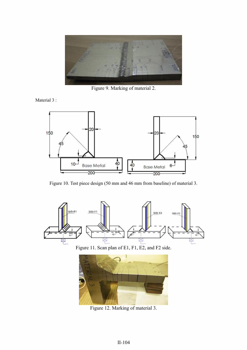
Figure 9. Marking of material 2.
Material 3 :
Figure 10. Test piece design (50 mm and 46 mm from baseline) of material 3.
Figure 11. Scan plan of E1, F1, E2, and F2 side.
Figure 12. Marking of material 3.
II-104

Preparing Tools For Testing
Figure 13. V1 and V2 calibration block.
Figure 14. Unit display.
RESULTS AND DISCUSSION
Material 1 Results
(a) (b)Figure 15. Scanning results obtained from transducer (a) 45˚ probe (b) 60˚
probe of A1 side.
(a) (b)Figure 16. Scanning results obtained from transducer (a) 70˚ of A1 side
(b) 45˚ of B1 side.
II-105

(a) (b)Figure 17. Scanning results obtained from transducer (a) 60˚ (b) 70˚ of B1 side.
Table 1. Comparison scanning side A1 and Side B1 using 45˚, 60˚ and 70˚ probes.Sisi A1 (t= 12 mm) Keterangan SISI B1 (t= 19 mm)
Sisi A1 (t= 12 mm) Keterangan SISI B1 (t= 19 mm)45˚ 45˚
45˚ 45˚60˚ 60˚
60˚ 60˚70˚ 70˚
70˚ 70˚
Jarak diskontinuitasJarak diskontinuitasbase metal : 12 mmbase metal : 12 mm
terhadapterhadap
Sisi A1 (t= 12 mm) KeteranganSisi A1 (t= 12 mm) Keterangan
45˚
45˚60˚60˚70˚
70˚
Applicable =Applicable =
Not Applicable =Not Applicable =
SISI B1 (t= 19SISI B1 (t= 19
45˚45˚60˚60˚70˚
Sisi A170˚(t= 12
45˚60˚70˚
mm)mm)
mm)
Jarak diskontinuitas terhadapJarak diskontinuitas terhadapbase metal : 16 mmbase metal : 16 mm
Keterangan SISI B1 (t= 19 mm)
45˚ Jarak diskontinuitas terhadap
60˚ base metal : 12 mm70˚
Sisi A1 (t= 12 mm) Keterangan SISI B1 (t= 19 mm) Jarak diskontinuitasBased on Table 1 it is found that the 45˚ angle45˚probe cannot be applied because45˚ thebase metal : 16 mmprobe shoe crashed into the weld capping so it cannot reach leg 1 well. Testing from the
60˚ 60˚70˚ 70˚
A1 side cannot be applied by all angle probes used because the discontinuity in the weldarea is higher than the thickness of the A1 side material. The location of discontinuities
Applicable =parallel to the direction of ultrasonic wave reflection shows two indications
Not Applicable =
simultaneously displayed on the screen so that the test operator must know whichdiscontinuities are relevant. Only probe 60˚ and 70˚ from the B1 side can be applied tothis material condition because the distance and depth of discontinuity obtained are veryvalid. Applicable means the angle probe can be used properly and not applicable is anunusable angle probe.
terhadap
A2 and B2 side :
(a) (b)Figure 18. Scanning results obtained from transducer (a) 45˚ (b) 60˚ of A2 side.
II-106

(a) (b)Figure 19. Scanning results obtained from transducer (a) 70˚ of A2 side (b) 45˚ of B2
side.
(a) (b)Figure 20. Scanning results obtained from transducer (a) 60˚ (b) 70˚ of B2 side.
Table 2. Comparison scanning side A2 and Side B2 using 45˚, 60˚ and 70˚ probes.
Sisi B2 (t= 19 mm) Keterangan SISI A2 (tt= 12 mm)45˚ 45˚ Jarak diskontinuitas tterhadap60˚ 60˚ base metall :: 5 mm70˚ 70˚
Sisi B2 (t= 19 mm) Keterangan SISI A2 (t= 12 mm)
45˚ 45˚ Jarak diskontinuitas tterhadap60˚ 60˚ base mettall :: 10 mm70˚ 70˚
Applicable =Nott Applicable =
Sisi B2 (t= 19 mm) Keterangan SISI A2 (t= 12 mm)
45˚ 45˚ Jarak diskontinuitas terhadap60˚ 60˚ base metal : 5 mm
Based on Table 2, shows that the 45˚ angle probe cannot be applied because the probe
70˚ 70˚shoe crashed into the weld capping so it cannot reach leg 1 as well. Testing from A2and B2 can be applied by using 60˚ and 70˚ angle probes because the location of
Sisi B2 (t= 19 mm) Keterangan SISI A2 (t= 12 mm)
discontinuities that does not exceed the thickness of the material, also the distance and45˚ 45˚ Jarak diskontinuitas terhadap
depth of the discontinuities detected by60˚both probes are valid. The location60˚ baseof metal : 10 mm70˚ 70˚
discontinuities parallel to the direction of ultrasonic wave reflection shows twoindications simultaneously displayed on the screen so that the test operator must know
Applicable =which discontinuities are relevant. The thinner side of the material may indicate a valid
Not Applicable =
distance, but not 100% accurate to measure the depth of discontinuity. This is becausethe reflected sound waves and the thickness of the material become different so that thedevice cannot be well responded to by the unit display. Applicable means the angleprobe can be used properly and not applicable is an unusable angle probe.

Material 2 Results
(a) (b)Figure 21. Scanning results obtained from transducer (a) 45˚ (b) 60˚ of C1 side.
(a) (b)Figure 22. Scanning results obtained from transducer (a) 70˚ of C1 side (b)
45˚ of D1 side.
(a) (b)Figure 23. Scanning results obtained from transducer (a) 60˚ (b) 70˚ of D1 side.
Table 3. Comparison scanning side C1 and Side D1 using 45˚, 60˚ and 70˚ probes.Sisi C1 (t= 12 mm) Keterangan SISI D1 (t= 19 mm)
45˚ 45˚
60˚ 60˚
70˚ 70˚
Applicable = Jarak diskontinuitas terhadap
Not Applicable = base metal : 5 mm
Sisi C1 (t= 12 mm) Keterangan SISI D1 (t= 19
Based on Table 3 it is found that the 45˚ angle probe cannot45˚ be applied because 45˚theprobe shoe meets the weld capping so it cannot reach leg60˚1 as well. Scanning from 60˚the
70˚ 70˚
D1 side the 45˚ angle probes cannot be applied because of the angle beam changed, sothe ultrasonic wave is not as expected. Testing from the C1Applicableand =D1 sidesJarakcandiskontinuitbeappliedsterhadap
Not Applicable = base metal : 5 mm
properly by using 60˚ and 70˚ angle probes due to the discontinuity locations do notexceed the thickness of the material. The distance and depth of the discontinuitiesdetected by both probes are valid. Good surface conditions can make testing easier.Applicable means the angle probe can be used properly and not applicable is anunusable angle probe.
mm)

(a) (b)Figure 24. Scanning results obtained from transducer (a) 45˚ (b) 60˚ of C2 side.
(a) (b)Figure 25. Scanning results obtained from transducer (a) 70˚ of C2 side (b)
45˚ of D2 side.
(a) (b)Figure 26. Scanning results obtained from transducer (a) 60˚ (b) 70˚ of D2 side.
Table 4. Comparison scanning side C2 and Side D2 using 45˚, 60˚ and 70˚ probes.
Sisi D2 (t= 19 mm) Keterangan SISI C2 (t= 12 mm)
45˚ 45˚60˚ 60˚
70˚ 70˚
Applicable = Jarak diskontinuitas terhadap
Not Applicable = base metal : 10 mm
Based on Table 4 a great probe used for scanning SisimaterialD2(t=19 mm)are 60˚ andKeterangan70˚. In theSISI 45˚C2(t= 1245˚ 45˚
probe, the scan angle changes so the emitted waves are invalid for testing, the thinner60˚ 60˚
side of material inspection the probe shoe does not reach70˚ leg 1. On the C2 side shows70˚
that the 45˚ angle probe cannot be applied because the probe shoe crashes the weldApplicable = Jarak diskontinuitas terhadap
capping so that cannot reach leg 1 well. Scanning from the D2 side of the 45˚ angleN t Applicable = base metal : 10 mm
probe cannot be applied because the probe undergoes a change in the angle of the beam,so the ultrasonic waveform is not as expected. The tests of the C2 and D2 sides can bewell applied by using angle probes 60˚ and 70˚ due to discontinuity locations that do notexceed the thickness of the material. The distance and depth of the discontinuitiesdetected by both probes are valid. Good surface conditions can make testing easier.Applicable means the angle probe can be used properly and not Applicable is anunusable angle probe.
mm)

Material 3 Results
Every manuscript must be make a conclusion from this research in the end of manuscript. Conclusion is made based on the research results or finding.
(a) (b)Figure 27. Scanning results obtained from transducer (a) 45˚ (b) 60˚ of E1 side.
Sisi E1 (t= 20 mm) (a)Jarak
Figure 2845˚.Scanningresults 60˚
Kedalaman (b)obtained from transducer (a) 70˚ (b) 45˚ using t = 45 mm of
E1 side.70˚ Applicable =
Table 5. Scanning results of E1 side.
Sisi E1 (t= 45 mm) Jarak Kedalaman
45˚
Sisi E1 (t= 20 mm) Jarak Kedalaman
45˚
60˚
70˚
Not Applicable =
Applicable =
Not Applicable =
Sisi E1 (t= 45 mm) Jarak Kedalaman
Based on Table 5, all probes on the test from E1 side show no indication detected on the45˚
screen, this is because the discontinuity location is outside the area of leg 1 and leg 2.For inputting thickness of material t = 45 mm to make leg 1 and leg 2 and insert thethickness of the material on the unit display, the discontinuity can be detected with avalid distance, but for the depth of discontinuity is invalid. This is because the reflectionof ultrasonic waves should be precisely at a depth of 45 mm, but in reality, only 20 mm.Probes 60˚ and 70˚ cannot be used because leg 1 and leg 2 are generated very far, so theresults obtained become less applicable and require more space and material length.Applicable means the angle probe can be used properly, and not applicable is anunusable angle probe.

(a) (b)Figure 29. Scanning results obtained from transducer (a) 45˚ (b) 60˚ of F1 side.
(a) (b)Figure 30. Scanning results obtained from transducer (a) 70˚ (b) 45˚ using t = 45 mm
of E1 side.
Table 6. Scanning results of F1 side.Sisi F1 (t= 20 mm) Jarak Kedalaman
Sisi F1 (t= 20 mm) Jarak Kedalaman
45˚60˚
70˚
Sisi E1 (t= 45 mm)) Jarak Kedalamanman
45˚
ApplicableApplicable=
NotNotApplicable=
=
=
Based on Table 6 all probes on the test from the F1 side show no indication detected on the screen, this is because the discontinuity location is outside the area of leg 1 and leg2. The use of probe 45˚ and 60˚ cannot be applied because the probe shoe meets theweld capping. Inputting thickness of material t = 45 mm to make leg 1 and leg 2 andinsert the thickness of the material on the unit display, the discontinuity can be detectedwith a valid distance, but for the depth is invalid. This is because the reflection ofultrasonic waves should be precisely at a depth of 45 mm, but in reality, only 20 mm.Probes 60˚ and 70˚ are not used because leg 1 and leg 2 are generated very far, so theresult obtained becomes less applicable and requires more space and material length.Applicable means the angle probe can be used properly and not applicable is anunusable angle probe.
(a) (b)Figure 31. Scanning results obtained from transducer (a) 45˚ (b) 60˚ of E2 side.

(a) (b)Figure 32. Scanning results obtained from transducer (a) 70˚ (b) 45˚ with
varian thickness of E2 side.
(a) (b)Figure 33. Scanning results obtained from transducer (a) 60˚ (b) 70˚ with
varian thickness of E2 side.
Table 7. Scanning results of E2 side.Sisi E2 (t= 20 mm) Jarak KedalamanSisi E2 (t= 20 mm) Jarak KedalamanSisi E2 (t= 20 mm) Jarak Kedalaman
45˚
45˚6045˚60˚670˚
70˚
70˚
Applicable =Applicable =
Not Applicable =Not Applicable =
Sisi E2 (t= xx mm)Sisi E2 (t= xx mm)
Sisi E2 (t= xx mm)45˚
45˚6045˚ Sisi F2 (t= 2060˚670˚
70˚ 45˚70˚60˚Sisi E2 (t= ∞)
Sisi E2 (t= ∞)70˚Sisi E2 (t= ∞)
45˚
45˚45˚
Jarak KedalamanJarak KedalamanJarak Kedalaman
mm) Jarak
Jarak KedalamanJarak Kedalaman
Jarak Kedalaman
Not Applicable =xx = Jarak minimum permukaan probe xx = Jarak minimum
permukaan probe xx = Jaterhadapakminimum permukaan probediskontinuitas
Kedalamanterhadap diskontinuitasterhadap diskontinuitas
Applicable =
Not Applicable =
Sisi F2 (t= xx mm) Jarak Kedalaman45˚ xx = Jarak minimum permukaan probe
Based on Table 7 the use of 45˚, 60˚, and 70˚ probes can be applied to detect the60˚ terhadap diskontinuitas
distance of discontinuity. The use of probe 45˚, 60˚, and 70˚ with material thickness t =70˚
20 mm cannot be used as well to detect the depth of discontinuity. Modified/addeddepth of at least xx mm can be well through leg 1 by all probes. In the use of thickness
Sisi F2 (t= ∞) Jarak Kedalaman
of material t = 45 mm to make leg 1 and leg 2 and insert it to unit display, cannot be45˚
applied properly to detect the discontinuity using a 45˚ probe. When the thickness isadded to devices that are too high / exceeds the length of the weld, the 45˚ probe cannotdetect the distance and depth of the discontinuity as well. The 60˚ and 70˚ probes cannotbe used because leg 1 and leg 2 are generated very far, so the result is less applicableand requires more space and material length. Applicable means the angle probe can beused properly and not applicable is an unusable angle probe. The distance of xx can beseen in Figure above.

(a) (b)Figure 34. Scanning results obtained from transducer (a) 45˚ (b) 60˚ of F2 side.
(a) (b)Figure 35. Scanning results obtained from transducer (a) 70˚ (b) 45˚
with varian thickness of F2 side.
(a) (b)Figure 36. Scanning results obtained from transducer (a) 60˚ (b) 70˚
with varian thickness of F2 side.
Sisi F2 (t= 20 mm) Jarak Kedalaman
Table 8. 45˚Scanning results of F2 side.Sisi F2 (t=60˚20 mm)Sisi F2 (t= 20 mm)
45˚70˚45˚60˚60˚70˚
Sisi F270˚(t= xx mm)
Sisi F2 (t=45˚xx mm)
Sisi F2 (t=45˚60˚xx mm)45˚
60˚70˚60˚
70˚70˚
Sisi F2 (t= ∞)Sisi F2 (t= ∞)Sisi F2 45˚(t=∞)
45˚45˚
Jarak KedalamanJarak Kedalaman
Applicable =Not Applicable =
Jarak KedalamanApplicable =
Applicable =Not Applicable =
Not Applicable =Jarak Kedalaman xx = Jarak minimum permukaan probe
Jarak Kedalaman terhadap diskontinuitasxx = Jarak minimum permukaan probe
xx = Jarak minimum permukaan probeterhadap diskontinuitas
terhadap diskontinuitas
Jarak KedalamanJarak Kedalaman
Jarak Kedalaman
Based on Table 8 the use of 45˚, 60˚, and 70˚ probes can be applied to detect thedistance of discontinuity. The use of probe 45˚, 60˚, and 70˚ with material thickness t =20 mm cannot be used as well to detect the depth of discontinuity. Modified/addeddepth of at least xx mm can be well through leg 1 by all probes. In the use of thicknessof material t = 45 mm to make leg 1 and leg 2 and insert it to unit display, cannot beapplied properly to detect the discontinuity using a 45˚ probe. When the thickness isadded to devices that are too high / exceeds the length of the weld, the 45˚ probe cannotdetect the distance and depth of the discontinuity as well. The 60˚ and 70˚ probes cannot

be used because leg 1 and leg 2 are generated very far, so the result is less applicableand requires more space and material length. Applicable means the angle probe can beused properly and not applicable is an unusable angle probe. The distance of xx can beseen in Figure above.
CONCLUSION
After conducted experiments and research then the conclusion of this paper are as follows:
Butt Joint
1. Based on the type of weld joints, the method that shows the best probe accuracy is60˚ and 70˚ probes.
2. Probes used in less couplant, rough surfaces, and oblique result in inaccurate test results.
3. The thicker side is highly optimized for inspection compared to the thinner side.4. The type of connection and the shape of the material greatly affect the results of
ultrasonic testing.5. Based on the result of an artificial defect, all probes can reach the location of
discontinuity if the condition is in accordance with the direction of ultrasonic wavedirection.
6. In the non-chamfered weld joints, the best probe to use is a 60˚ and 70˚ probe from a thicker side (sides B1 and B2).
7. In the weld joints of the material with the chamfer, the most used probes are 60˚ and 70˚of the thicker or thinner sides (C1, D1, C2, and D2 sides).
T Joint
1. To determine the location of the discontinuities, using normal probes first then investigated further using angle probes with material thickness tw1 or tw2.
2. In the T-joint weld joints, E1 and F1 sides cannot be inspected with probes 45˚, 60˚,or 70˚. The most optimal side for testing is E2 and F2, but the depth of discontinuitycannot be detected properly because the height/location of the discontinuity exceedsthe thickness of the material.
3. For discontinuity locations within tm (thickness of material), valid probes to used isthe 70˚ from the E1 and F1 sides, whereas, from the E2 and F2 sides the valid probesused are 45˚ and 60˚.
4. For discontinuity locations that are beyond tm (thicker material) all angle probes cannot be applied by using t = tm.

ACKNOWLEDGEMENTS
The authors would like to be obliged to Institut Teknologi Sepuluh Nopember for providing laboratory facilities.
REFERENCES
Berke, M. (1992). Nondestructve Material with Ultrasonic – Introduction to the Basic Principles. Krautkramer. Berlin : Springer-Verlag.
Hellier, C. J. (2003). Handbook of Nondestructive Evaluation. New York: McGraw-Hill Companies.
Willcox, M dan Downes G. (2003). A Brief Description of NDT Techniques. Hereford:Insight NDT.