ultrasound system ebqa test device - aapm
TRANSCRIPT

Ultrasound System EBQA Test Device
G. Wayne Moore, B.Sc., MA, FASEJuly, 2010AAPM Annual Conference

What we will cover• Historical Perspective of Ultrasound Technology
• Development Rationale
• FirstAssist – Probe Emulator Device
• Intended Use
• Theory of Operation
• Captured and Displayed Data
• Indicators of Performance Variances
Ultrasound System EBQA Test Device

Ultrasound System EBQA Test Device
Ultrasound System Design Architecture50 Years of Development

Diagnostic UltrasoundHistory of Modern Diagnostic Ultrasound
•A-Mode•M-Mode•B-Scan•Mechanically Steered Real-time•Linear Array Real-time•Zero-crossing Doppler•Spectral Doppler (FFT)•Phased Array Real-time•CW Doppler in Probe – Bernoulli Equation•Color Flow Doppler•Triplex modes of Operation•Pseudo-Color•Color “Angio” & Power Doppler•Harmonic Imaging & Variants•Contrast Media Imaging•Spatial Compounding•3D Imaging – Volumetric•4D Imaging – Steered Curved Array•Phase Aberration Correction
t
Evidence-Based Quality Assurance in Ultrasound

Ventricular Septal Defect
Evidence-Based Quality Assurance in Ultrasound
BPD

Development Challenges and Rationale
Traditional Methods of Performance Evaluation
Are No Longer Relevant
Error Code: Yf6533RA7LLOp1
Translation: Non-deterministic Software Error

• Currently Available Tools– On-board Diagnostics
- May have partial or no access- Only tests system (not probes)- Generally poor accuracy
– Tissue Mimicking Phantom+ Relatively inexpensive (~ $2000)+ Widely used in industry last 15 years- Affected by environment- Most brands are susceptible to damage- Defective systems and transducers can appear to be OK
- Results are very user dependent- Only tests 1 operating mode (usually B-mode)
“…it is impossible to state or test a tolerance of a
machine acquisition error by itself”
Philips Ultrasound Op Man
Development Challenges and Rationale

• Great performance variability among different machines
• Measurement differences and therefore ultimate accuracy is
machine dependent
• Operator variability
• Recognizing system performance change due to component
degradation is a key early warning indicator
Development Challenges and Rationale

“Variability among transducers and systems is a significant factor. Transducer variability results from piezoelectric crystal
efficiencies, process-related impedance differences, and sensitive lens focusing parameter variations. Differences in
system pulser voltage control and efficiencies is also a contributor to variability.”
Philips Op Man
Development Challenges and Rationale

Acquisition and Algorithmic Errors
“Acquisition errors are introduced by ultrasound machine electronics, relating to the front end signal acquisition, signal conversion and the display of the image on the screen….it is impossible to state or test a
tolerance of a machine acquisition error by itself.”
“Algorithmic error is the error introduced by taking the basic measurement acquisition error as input to higher order calculations for display to the user…this error is also subject to errors introduced by rounding versus
truncating results for a given level of significant digit display of the values.”
Example: The Bernoulli Equation 4V2
Development Challenges and Rationale

Acoustic Artifacts
“…the control choices made by the sonographer that affectamplification, signal processing, and echo display can lead to
significant differences in the displayed appearance of echo data.”
“…artifacts can originate from misadjusted equipment.”
Development Challenges and Rationale

Development Approach

Probe Emulator
Development Approach

Development Approach

Development Approach
Intended Use1) Validate Manufacturer’s Performance Specifications2) Verify reception of transmit signals from each transmitter3) Input signals of various amplitudes into each receive channel4) B-mode, Spectral Doppler, Color Flow and other variant modes
What Modes will the FirstAssist Signal be Seen on the System Monitor?
1) B-mode, along with various special processing schemes such as:a) SonoCT (spatial compounding)b) 2nd Harmonic Imagingc) Dynamic Focusing
1) M-Mode2) Spectral Doppler3) Color Flow

Development Approach -

Diagnostics
Super User Access
Indi
rect
Te
st
FirstAssist
Calibrate Touch ScreenReload all Drivers
DICOM Server Set Up
Tech Admin
Unisyn’s way allows the same access via CMCAA*
compliant technology
iE33 and iU22
B-M
ode
Calip
ersCF
I
Volta
ges
Dop
pler
Intensity Levels
Intensity Levels& Velocity
ProbeMux EXmit E
Dir
ect
Test
EBQA∆’s InPerformanceOver time
Boar
d ID
Erro
r Log
Minor Service Diagnostics
ErrorDetection
* Computer Maintenance Competition Assurance Act
Unisyn’s way allows the same access via CMCAA*
compliant technology
For Example:“An error has been detected.
Please record the following and call technical support.”
Diag Code: 200.BWRU.8YMD.5Software Build Version: 1.1.1.504
Development Approach
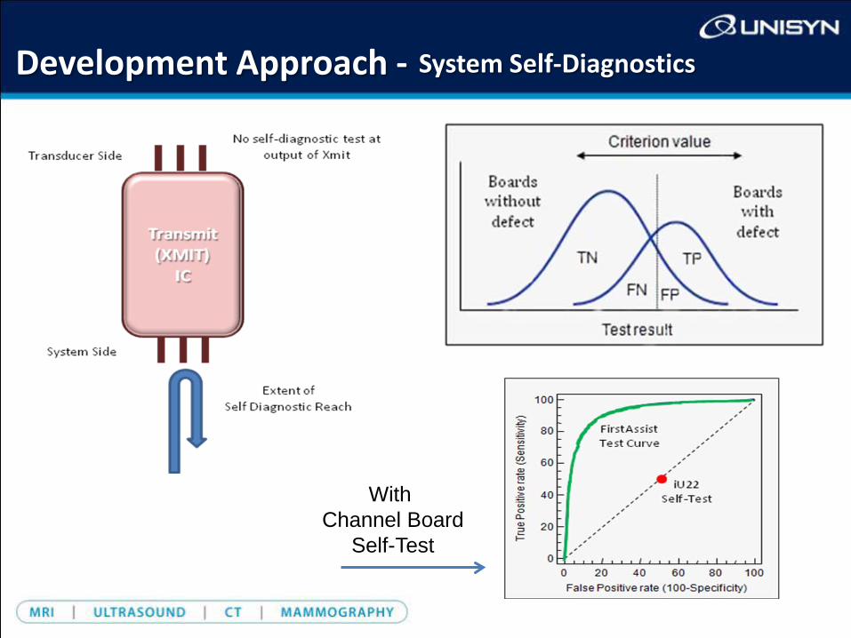
Development Approach - System Self-Diagnostics
With Channel Board
Self-Test

Development Approach
Block Diagram
John Timms
Tested Channels: 1-32Mean Vpp (Blue Line): 151, Standard Deviation: 28.0Purple line (if visible) is the mean plus 3 standard deviation.Gold line (if visible) is the mean minus 3 standard deviation.
OVERALL result: Fail - 1 warnings, 3 failures.Detail:• Failure: Channel 15 Transmit, No signal was captured (Channel Board 2).• Failure: Channel 18 Transmit, No signal was captured (Channel Board 2).• Failure: Channel 24 Transmit, No signal was captured (Channel Board 2).• Warning: Warning: Channel 9 (Channel Board 2) is an outlier.

Development Approach


End of Presentation