uml and the software lifecycle. what is uml? unified modelling language developed to enable it...
Post on 21-Dec-2015
215 views
TRANSCRIPT

UML and the Software Lifecycle

What is UML?
• Unified Modelling language • Developed to enable IT professionals to model
computer applications in a standard language-independent way.
• UML provides diagrams that increase the ease of understanding of an application under development
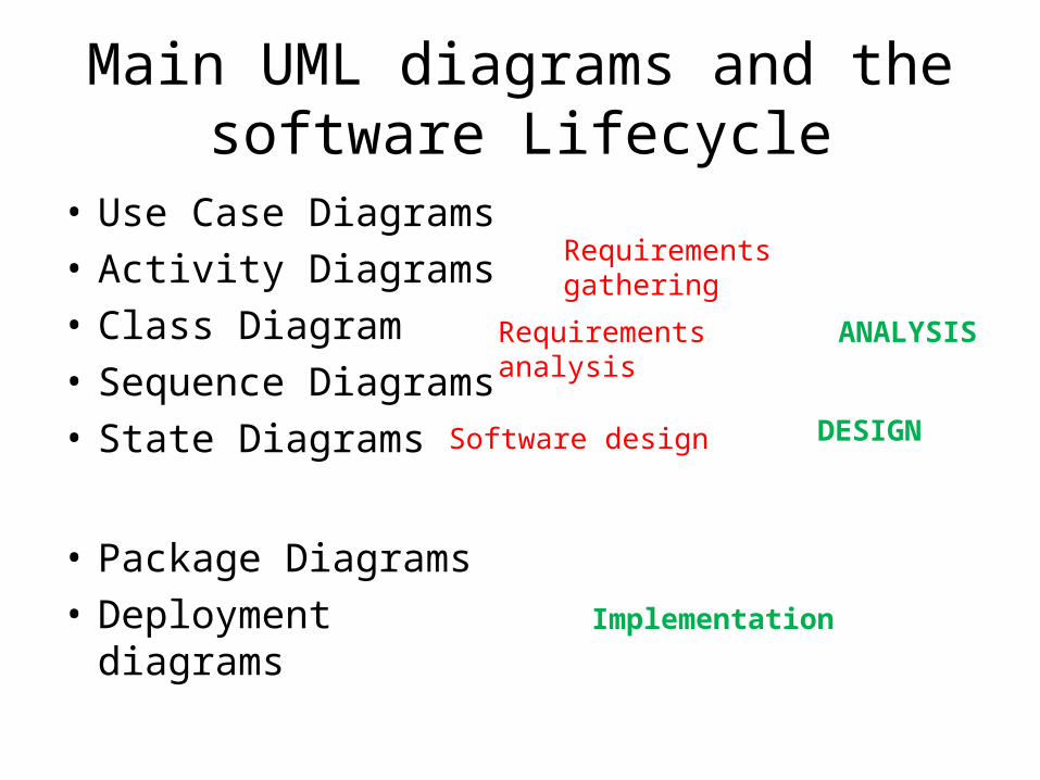
Main UML diagrams and the software Lifecycle
• Use Case Diagrams• Activity Diagrams• Class Diagram• Sequence Diagrams• State Diagrams
• Package Diagrams• Deployment diagrams
Requirements gathering
Requirements analysis
DESIGN
Implementation
ANALYSIS
Software design

Requirements Gathering: Use Case Diagram shows SCOPE
Source: IBM Rational

.
.

Use Case Diagrams
• Business requirements – essential use cases
Guest
Order food/drink
Bookspa
Request alarm call
Hotel self service subsystem
Check valid room number
<<includes>>

Each Use Case• Describes a system function from a user’s
perspective• Details business events and users interaction
with the system during that event• Represents a system activity, a well-defined
part of the system’s functionality• Has a goal• Supported by behaviour specifications• Has a more detailed description, possibly
specifying a number of scenarios or alternate courses of action

• Use cases are initially defined at a high level and successively refined as the analysis and software development process unfolds.
Williams 2004

• The UML Class Diagram provides a model that can be easily translated into software components.
• Use case realisation includes identifying a set of classes with an understanding of how they work together to provide the functionality of the use case.
Williams 2004
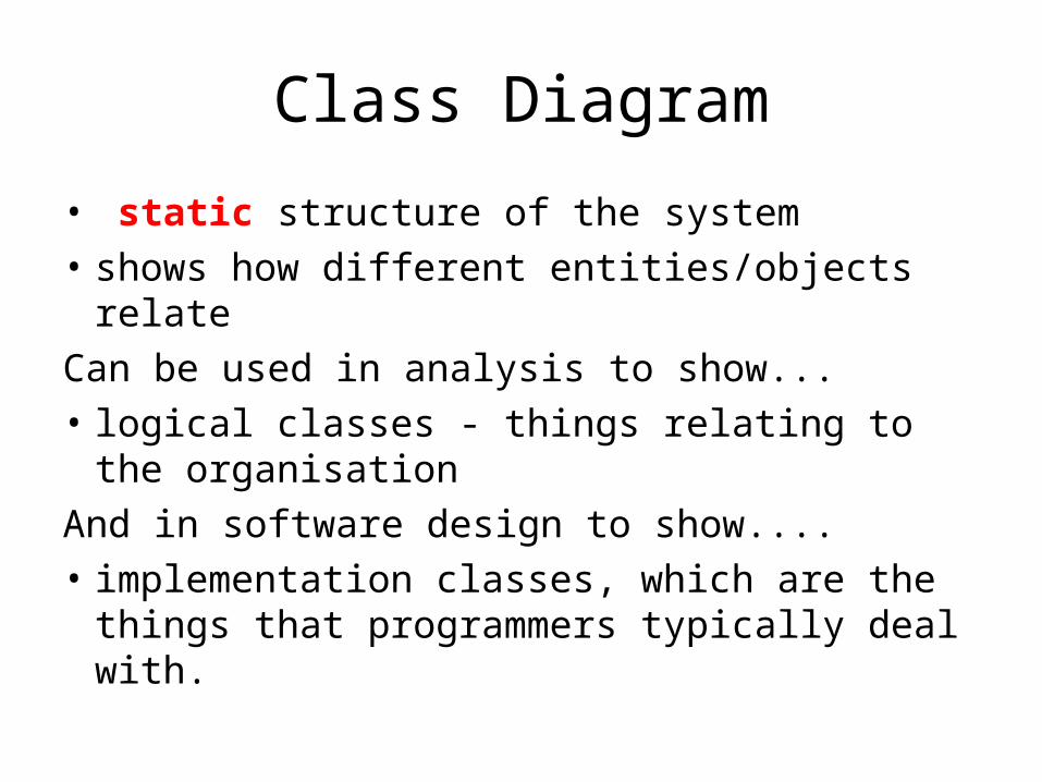
Class Diagram
• static structure of the system• shows how different entities/objects relateCan be used in analysis to show... • logical classes - things relating to the
organisationAnd in software design to show....• implementation classes, which are the things
that programmers typically deal with.

• The class diagram is refined and modified through the lifecycle to add more detail relevant to the implementation

Example class diagram<boundary>
User Interface:: addmemberUI
Startnewmember()
Createnewmember()
Select membertype()
Recordpayment()
<control>
Control:: addmember
Select membertype()
Recordpayment()
Createnewmember()
<entity>
Member
Name
Address
Phone
Mobile
Type
Createnewmember()
Update membertype()
Updatememberdetails()
Deletemember()
<entity>
Filmclub
Club name
Location
Night
Time
Contact
Phone
Create filmclub()
1 0..*
Is made up of

Williams 2004

Class diagrams can show
• Inheritance relationships• Association relationships (like in E-R diagrams)

Activity Diagrams
• Activity diagrams are used to show sequences of activities.
• show workflows from start point to finish point detailing the many decision paths that exist in the progression of events contained in the activity.
• can be used to model higher-level business processes or low-level internal class actions.
• Swim lanes can be used to show who is responsible for an action

Activity Diagrams

Activity diagram with swimlanes
Source: IBM Rational http://www.ibm.com/developerworks/rational/library/769.html

Statechart Diagram
• The statechart diagram models the different states that a class can be in and how that class transitions from state to state
• Only necessary for classes with 3 or more states.
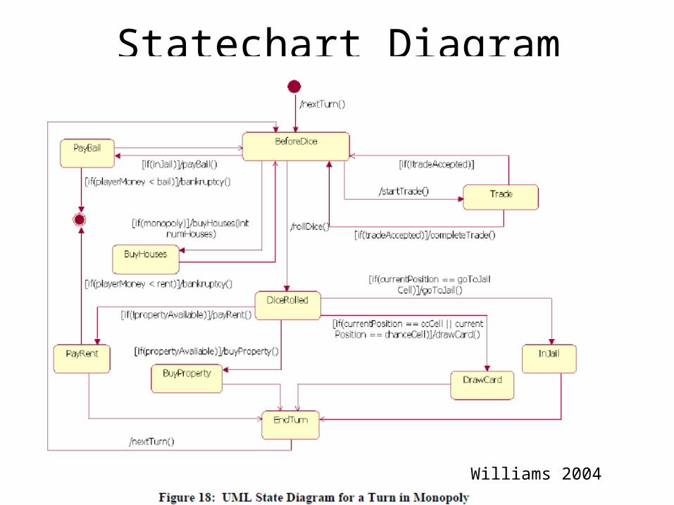
Statechart Diagram
Williams 2004

Sequence Diagrams
• Dynamic view of the system• represent or model the flow of messages, events
and actions between the objects in a system. • show the calls between the different objects in
their sequence for a use case or part of a use case
• used to design, document and validate the architecture, interfaces and logic of the system

Sequence Diagrams

Williams 2004
Component Diagram
• physical view of the system• shows the dependencies that the software has on
other software components (e.g. software libraries) in the system.
• The diagram can be shown at a very high level, with just the large-grain components, or it can be shown at the component package level.
• [Note: The phrase component package level is a programming language-neutral way of referring to class container levels such as .NET's namespaces (e.g., System.Web.UI) or Java's packages (e.g., java.util).]
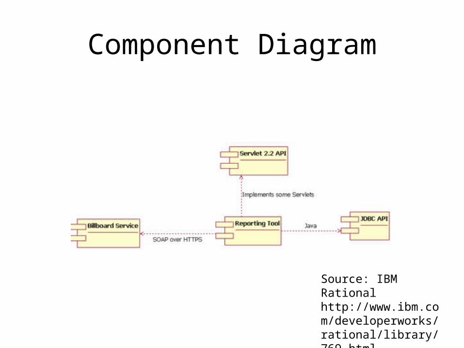
Component Diagram
Source: IBM Rational http://www.ibm.com/developerworks/rational/library/769.html

Deployment Diagram
• shows how a system will be physically deployed in the hardware environment
• where the different components of the system will physically run and how they will communicate with each other.
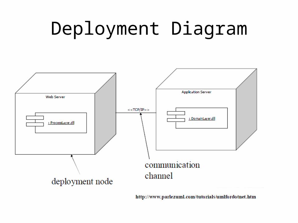
Deployment Diagram

Sources
• Williams, Laurie (2004) An Introduction to the UML Modelling Language
• IBM Rational - UML Overview http://www.ibm.com/developerworks/rational/library/769.html