uml diagramming guide.backup - pacestar · this uml diagramming guide is a companion to the...
TRANSCRIPT
A Supplementary Guide to Pacestar UML Diagrammer 6.0
UML Diagramming Guide

Pacestar UML DiagrammerVersion 6.0 for Windows
UML Diagramming Guide
IMPORANT NOTICE:Copyright © 2009 Pacestar Software. All rights reserved worldwide.
Information in this document is subject to change without notice. No part of this document may be reproduced in any form or by any means - graphic, electronic, or mechanical - including photocopying, recording, taping, or storage in any information retrieval system, for any purpose other than to aid a licensed user directly in the usage of the software, or when authorized in writing by Pacestar Software.
Pacestar Software retains all ownership rights to this computer program and its documentation. The source code is a confidential trade secret of Pacestar Software. You may not attempt to decipher or decompile the program or develop source code for it, or knowingly allow others to do so. Making copies of the program (except for archival purposes or as an essential step in the use of the program) is prohibited. The program and its documentation may not be sublicensed and may not be transferred without the prior written consent of Pacestar Software.
Pacestar Software PROVIDES THIS PUBLICATION “AS IS” WITHOUT WARRANTY OF ANY KIND, EXPRESS OR IMPLIED. Pacestar Software may revise this publication from time to time without notice. Every attempt has been made to assure that this manual provides the most current and accurate information possible.
ACKNOWLEDGEMENTS:All copyrights and trademarks mentioned herein belong to their respective owners. Pacestar Software is a trademark of Pacestar Software. Windows is a registered trademark of Microsoft Corporation. Microsoft Word is a registered trademark of Microsoft Corporation.

Table of Contents 1
TABLE OF CONTENTSAbout This Guide ............................................................................................................ 9
Symbols and Conventions.........................................................................................................9
General Techniques ..................................................................................................... 11General Style Usage Tables ...................................................................................................11Keywords.................................................................................................................................11Attachable Nodes ....................................................................................................................12
Attaching Attachable Nodes to Base Nodes.....................................................................13Repositioning Attachable Nodes.......................................................................................13Detaching Attachable Nodes from Base Nodes................................................................14
Comments ...............................................................................................................................15Containers ...............................................................................................................................16Frames ....................................................................................................................................17Path Labels .............................................................................................................................18
In-line vs. Lateral Path Labels...........................................................................................18Flow Labels .............................................................................................................................19Off Center Path Connections ..................................................................................................19Path Trees...............................................................................................................................20
Creating Path Trees..........................................................................................................21Manipulating Path Trees ...................................................................................................21
Node Symbols Containing Internal Icons ................................................................................23Extensions and Nonstandard Symbols ...................................................................................23Miscellaneous Drawing ...........................................................................................................24
Activity Diagrams ......................................................................................................... 25Sample Activity Diagram .........................................................................................................25Activity Diagram Style Usage Tables ......................................................................................26Forks and Joins .......................................................................................................................28Object Flows and Object Flow States .....................................................................................28Conditional Branches and Decisions.......................................................................................29Pins .........................................................................................................................................29Listbox Pins .............................................................................................................................31Connectors ..............................................................................................................................32Exception Parameters .............................................................................................................32Interruptible Activity Regions...................................................................................................33
Class/Object Diagrams ................................................................................................ 35Sample Class Diagram............................................................................................................35Class/Object Diagram Style Usage Tables .............................................................................36Associations ............................................................................................................................40
Association Navigability ....................................................................................................40
UML Diagramming Guide
EDGE Diagrammer User’s Guide
Page 1 of 4
Last Modified May 18, 2009 5:39 pm
Filename: S:\UFLOW\UMLDOC\UML Diagramming Guide TOC.fm

2 Table Of Contents
Association End Labels ....................................................................................................41Association Multiplicities...................................................................................................41Association Names...........................................................................................................42Association Direction Indicators .......................................................................................42Association Constraints ....................................................................................................43Association Classes .........................................................................................................43N’ary Associations ............................................................................................................43
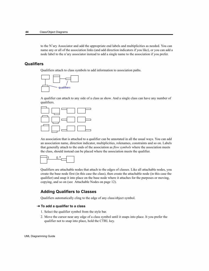
Qualifiers .................................................................................................................................44Adding Qualifiers to Classes ............................................................................................44Detaching Qualifiers from Classes ...................................................................................45
Templates ...............................................................................................................................45
Communication Diagrams ...........................................................................................47Sample Communication Diagram ...........................................................................................47Message Style Usage Tables .................................................................................................48Messages................................................................................................................................49
Creating Messages (Point-to-Point) .................................................................................49Creating Messages (Stamping) ........................................................................................50Labeling Messages...........................................................................................................51
Looping Messages..................................................................................................................51
Component/Deployment Diagrams .............................................................................53Sample Component Diagram..................................................................................................53Sample Deployment Diagram .................................................................................................54Component/Deployment Diagram Style Usage Tables...........................................................55Interfaces ................................................................................................................................56
Labeling Interfaces ...........................................................................................................58Moving Interfaces .............................................................................................................58
Assembly Connectors .............................................................................................................58Ports........................................................................................................................................59
Creating Ports...................................................................................................................60Labeling Ports...................................................................................................................60Attaching Interfaces to Ports ............................................................................................60Repositioning Ports ..........................................................................................................61
Composite Structure Diagrams ...................................................................................63Sample Composite Structure Diagram....................................................................................63
Interaction Overview Diagrams ...................................................................................65Sample Interaction Overview Diagram....................................................................................65
Package Diagrams ........................................................................................................67Sample Package Diagram ......................................................................................................67Package Diagram Style Usage Tables ...................................................................................68Containments ..........................................................................................................................69
UML Diagramming Guide
EDGE Diagrammer User’s Guide - Beta Version
Page 2 of 4
Last Modified May 18, 2009 5:39 pm
Filename: S:\UFLOW\UMLDOC\UML Diagramming Guide TOC.fm
Table of Contents 3
Sequence Diagrams ..................................................................................................... 71Sample Sequence Diagram ....................................................................................................71Sequence Diagram Style Usage Tables .................................................................................72Lifelines ...................................................................................................................................73Activations ...............................................................................................................................74Terminate Nodes.....................................................................................................................76Messages ................................................................................................................................76Recursion and Subactivations.................................................................................................79Guard Conditions on Activations and Lifelines........................................................................80States on Activations and Lifelines..........................................................................................80
State Diagrams ............................................................................................................. 81Sample State Diagram ............................................................................................................81State Diagram Style Usage Tables .........................................................................................82Superstates .............................................................................................................................84Concurrency Boundaries.........................................................................................................84Entry and Exit Points ...............................................................................................................85
Labeling Entry Points and Exit Points ...............................................................................85Alternate Notation for Entry and Exit Points......................................................................86
Self-transitions.........................................................................................................................86State Name Tabs ....................................................................................................................87
Use Case Diagrams ..................................................................................................... 89Sample Use Case Diagram.....................................................................................................89Use Case Diagram Style Usage Tables..................................................................................90Relationships...........................................................................................................................91
Unsupported ................................................................................................................. 93Timing Diagrams .....................................................................................................................93Parameter Sets .......................................................................................................................93Explicit Directions on Input and Output Pins ...........................................................................93General Ordering Path ............................................................................................................93Use Case Stereotype Symbol .................................................................................................94Information Class Stereotype Symbol .....................................................................................94Custom Stereotype Symbols...................................................................................................94
References .................................................................................................................... 95
UML Diagramming Guide
EDGE Diagrammer User’s Guide
Page 3 of 4
Last Modified May 18, 2009 5:39 pm
Filename: S:\UFLOW\UMLDOC\UML Diagramming Guide TOC.fm

4 Table Of Contents
UML Diagramming Guide
EDGE Diagrammer User’s Guide - Beta Version
Page 4 of 4
Last Modified May 18, 2009 5:39 pm
Filename: S:\UFLOW\UMLDOC\UML Diagramming Guide TOC.fm

9
About This Guide
This UML Diagramming Guide is a companion to the Pacestar UML Diagrammer software. Within this guide you will find techniques for developing and maintaining Unified Modeling Language diagrams using the features, templates, and symbols contained in the software. It will assume a basic understanding of the product and its diagramming features and terminology documented in Pacestar UML Diagrammer User Guide. Both this guide and the main user guide are duplicated in limited detail in online help modules accessible from within the software.
The version of Pacestar UML Diagrammer that accompanies this guide is based on UML 2.0 as defined by OMG and published in the official specification, and taking into account some of the more popular industry references. The notation we use for cross referencing the contributing reference publications is noted below in Symbols and Conventions. Where conflicts, discrepancies, or voids are apparent, we do our best to combine sources and weigh popular acceptance and usefulness in determining how to support the notation and terminology. The dynamic nature of UML and the abundance of tools and publications trying independently to pin it down, results in constantly changing requirements. Consider this guide to be advisory and certainly not authoritative in regard to the language notation. If any of the notation described becomes obsolete or falls in disfavor with the industry, you can use the more generic capabilities of the software to adapt.
How can I get the tool to something? Refer to the main User GuideHow can I diagram specific UML notation? Refer to this user guideWhat is proper UML notation? Refer to OMG specification or leading references
Please note that neither our developers nor our technical writers claim to be experts of UML usage. The descriptions, examples, and guidelines we provide are meant to be informative with regard to the software, not necessarily representative of good (or even proper) UML usage.
Symbols and ConventionsNames of keys on the keyboard are shown in small capital letters such as CTRL, ESC, and ENTER. Key combinations are shown as CTRL-C, ALT-F, and so on. Remember that keys may not be labeled exactly the same on your keyboard.Important terminology is italicized. Most terms are defined by UML, but some are our own inventions. Many are also terms that have been adopted by the software and are defined in the main user guide. Reference publications are listed in the appendix. When they are cross referenced in the text to explain standards, ambiguities, or conflicts they are denoted by a bracketed symbol and optional page number such as [SPEC231] (UML official specification page 231). The symbols are included in the References chapter.
UML Diagramming Guide
EDGE Diagrammer User’s Guide
Page 9 of 96
Last Modified May 18, 2009 5:39 pm
Filename: S:\UFLOW\UMLDOC\UML Diagramming Guide.fm

10
UML Diagramming Guide
EDGE Diagrammer User’s Guide - Beta Version
Page 10 of 96
Last Modified May 18, 2009 5:39 pm
Filename: S:\UFLOW\UMLDOC\UML Diagramming Guide.fm
CHAPTER1 GENERAL TECHNIQUES
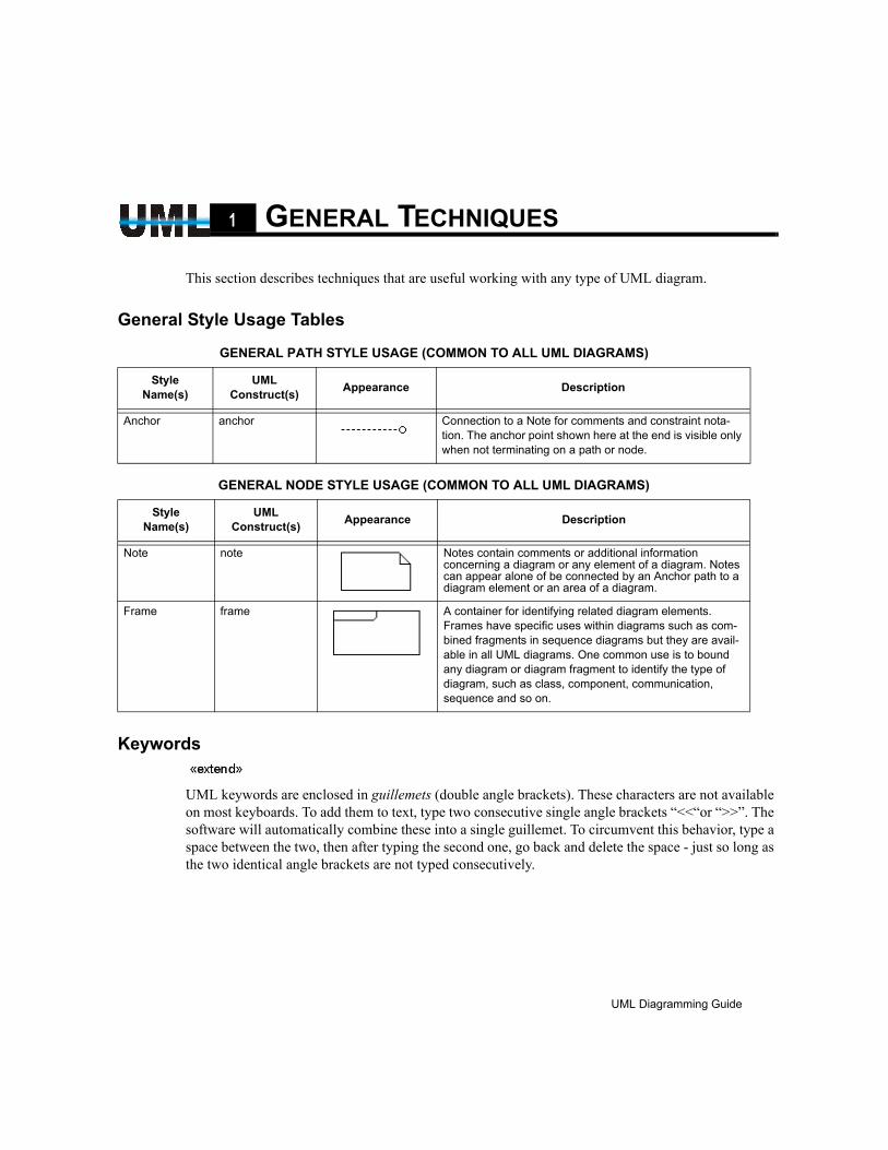
This section describes techniques that are useful working with any type of UML diagram.
General Style Usage Tables
Keywords
UML keywords are enclosed in guillemets (double angle brackets). These characters are not available on most keyboards. To add them to text, type two consecutive single angle brackets “<<“or “>>”. The software will automatically combine these into a single guillemet. To circumvent this behavior, type a space between the two, then after typing the second one, go back and delete the space - just so long as the two identical angle brackets are not typed consecutively.
GENERAL PATH STYLE USAGE (COMMON TO ALL UML DIAGRAMS)
StyleName(s)
UML Construct(s) Appearance Description
Anchor anchor Connection to a Note for comments and constraint nota-tion. The anchor point shown here at the end is visible only when not terminating on a path or node.
GENERAL NODE STYLE USAGE (COMMON TO ALL UML DIAGRAMS)
StyleName(s)
UML Construct(s) Appearance Description
Note note Notes contain comments or additional information concerning a diagram or any element of a diagram. Notes can appear alone of be connected by an Anchor path to a diagram element or an area of a diagram.
Frame frame A container for identifying related diagram elements. Frames have specific uses within diagrams such as com-bined fragments in sequence diagrams but they are avail-able in all UML diagrams. One common use is to bound any diagram or diagram fragment to identify the type of diagram, such as class, component, communication, sequence and so on.
UML Diagramming Guide
EDGE Diagrammer User’s Guide
Page 11 of 96
Last Modified May 18, 2009 5:39 pm
Filename: S:\UFLOW\UMLDOC\UML Diagramming Guide.fm

12 General Techniques
Attachable NodesUML notation contains a wide variety of nodes that attach to other nodes in different ways. For example, qualifiers attach to the outer edges of class nodes, ports attach to components, input and output pins attach to actions, and so on.
Pacestar UML Diagrammer allows you to attach certain nodes to others so that they can be manipulated together. In most cases, this relationship involves a base node and an attachable node that will attach to the base node. A port, for instance is an example of an attachable node that can be dragged to a component base node where it will snap into place and become attached to the component. The inverse is not true. A component cannot be dragged to attach it to a port. Most attachable node relationships have this sort of one-directional relationship with their base node. A notable exception are lifelines and activations which can be attached to objects bidirectionally. That is to say that objects can also be attached to activations or lifelines. The process of attaching
UML Diagramming Guide
EDGE Diagrammer User’s Guide - Beta Version
Page 12 of 96
Last Modified May 18, 2009 5:39 pm
Filename: S:\UFLOW\UMLDOC\UML Diagramming Guide.fm
General Techniques 13
nodes to one another is designed to be intuitive for the most part and to reflect the way that you would construct diagrams on paper.
Attaching Attachable Nodes to Base Nodes
To add an attachable node to base nodeWe’ll assume the base node is already on your diagram. In the case of a port that is to be attached to a component, the component is the base node, and the port is the attachable node.
1. Select the attachable node symbol from the style bar (a port for example). Be careful to select the proper attachable node for the base. It’s easy to confuse a port with a pin, but a port will only attach to a component and a pin will only attach to an action.
2. Move the cursor near the location of the base node where the attachable node will attach. The particular position depends on the relationship between the attachable node and the base node. In the case of a port and a component, the port attaches to any point overlapping the edge of the component, though it can also attach just inside the edge in the less common case of a private port. The software knows which nodes attach to which, and where they can attach.
3. When the cursor is located at a valid location where the attachable node is permitted to attach to the base node, the attachable node will snap into place. If for some reason you prefer for the node NOT to attach to the base node, simply hold down the CTRL key and it will not snap into place (nor will it become attached if you create it).
4. Click to create the attachable node on the base node. The attachable node (the port for example) will drop into place and attach to the base node (the component).
Once an node is attached to a base node, the node will remain attached to the base node when it is moved, copied, and duplicated. It will also be deleted when the base node is deleted. If you prefer to delete the base node not the attached nodes, simply detach them first.
NOTE: Some attachable nodes, notably the listbox pins and complex ports, have separate vertical and horizontal configurations (different styles). These can only be attached to the appropriate side in the way you might expect. The horizontal version of the symbol can only attach to the top and bottom edges of the base node, and the vertical symbol can only attach to the left and right sides.
Repositioning Attachable NodesAfter a node is attached to a base node, you can select it individually and drag it to reposition it to a different position on the base node. You can also move it away from the base node to detach it. Note that one exception is made for activations and lifelines and their attached objects. Because these relationships are bidirectional, moving either will move the other rather than repositioning. However, these nodes can only be attached in one way (top to bottom) so there is no need to reposition either.
UML Diagramming Guide
EDGE Diagrammer User’s Guide
Page 13 of 96
Last Modified May 18, 2009 5:39 pm
Filename: S:\UFLOW\UMLDOC\UML Diagramming Guide.fm
14 General Techniques
For example, to reposition a port that is attached to a component, simply select only the port and drag it until it snaps to an alternate location on the edge of the component. You can accomplish this by dragging the port when nothing is selected as well. If you select the port, but do not select the component, AND you select any other objects, the port will not move because the component to which it is attached is not being moved. While this is usually expected, you might be surprised to find that it also applies to other ports attached to the same component. If you attempt to drag more than one attached node at a time (with the intent of repositioning both) neither will move. Simply reposition one at a time instead.
NOTE: When duplicating (via CTRL-drag) an attached node, be sure to release the CTRL key before dropping the copy. Otherwise, the copy will not snap into place. The CTRL serves dual purposes, to create a duplicate, and to invoke freeform mode where the object being manipulated will ignore everything else in the diagram (will not attach when dropped for example).
Detaching Attachable Nodes from Base NodesA node that is attached to a base node can be detached so that it becomes independent of the base node. Once detached, it will no longer move along with the base node, be copied with it, or be automatically deleted when the base node is deleted. There are two ways to detach most attachable nodes from their base nodes.
To detach an attachable node from a base node (method 1)As described in the previous section, the easiest way to detach an attachable node from a base node is simply to select it individually and drag it away from the base node. Once it is out of range of the base node, dropping it will sever the relationship with the base. Be sure to drag the attached node when either (a) nothing is selected, or (b) only the attached node is selected, otherwise the base node will drag along as well and they will not become detached.
To detach an attachable node from a base node (method 2)An alternate way to detach a node from its base node is to right click on the attached node and select Detach from the context menu. For bidirectional attachments (such as a lifeline attached to an object), this is the only way to detach them.
UML Diagramming Guide
EDGE Diagrammer User’s Guide - Beta Version
Page 14 of 96
Last Modified May 18, 2009 5:39 pm
Filename: S:\UFLOW\UMLDOC\UML Diagramming Guide.fm

General Techniques 15
Comments
You can add comments anywhere within a type of UML diagram using a Note symbol. There’s nothing to prevent you from simply adding text annotations throughout your diagram for a similar purpose, but UML prefers that comments be contained within Note symbols. An added advantage is that you can use an Anchor path to attach a Note to a particular diagram element or direct it to any area of a diagram.
Comments can be simple descriptions that annotate your diagrams, or they can be actual components of diagrams such as constraints on classes or associations, or extension points in use cases.
When you want to associate a comment with a region of a diagram rather than with a specific
diagram element, you can use an anchor that ends with an anchor point as shown. An anchor point is a small circle that indicates that the comment is anchored to a position in a diagram rather than to a node or path. By default, an anchor point appear on an anchor when the terminating end it unattached to a path or node. You can create such an anchor by entering connect mode, choosing the anchor style, clicking on the note, then double clicking where the anchor should end.
UML Diagramming Guide
EDGE Diagrammer User’s Guide
Page 15 of 96
Last Modified May 18, 2009 5:39 pm
Filename: S:\UFLOW\UMLDOC\UML Diagramming Guide.fm
16 General Techniques
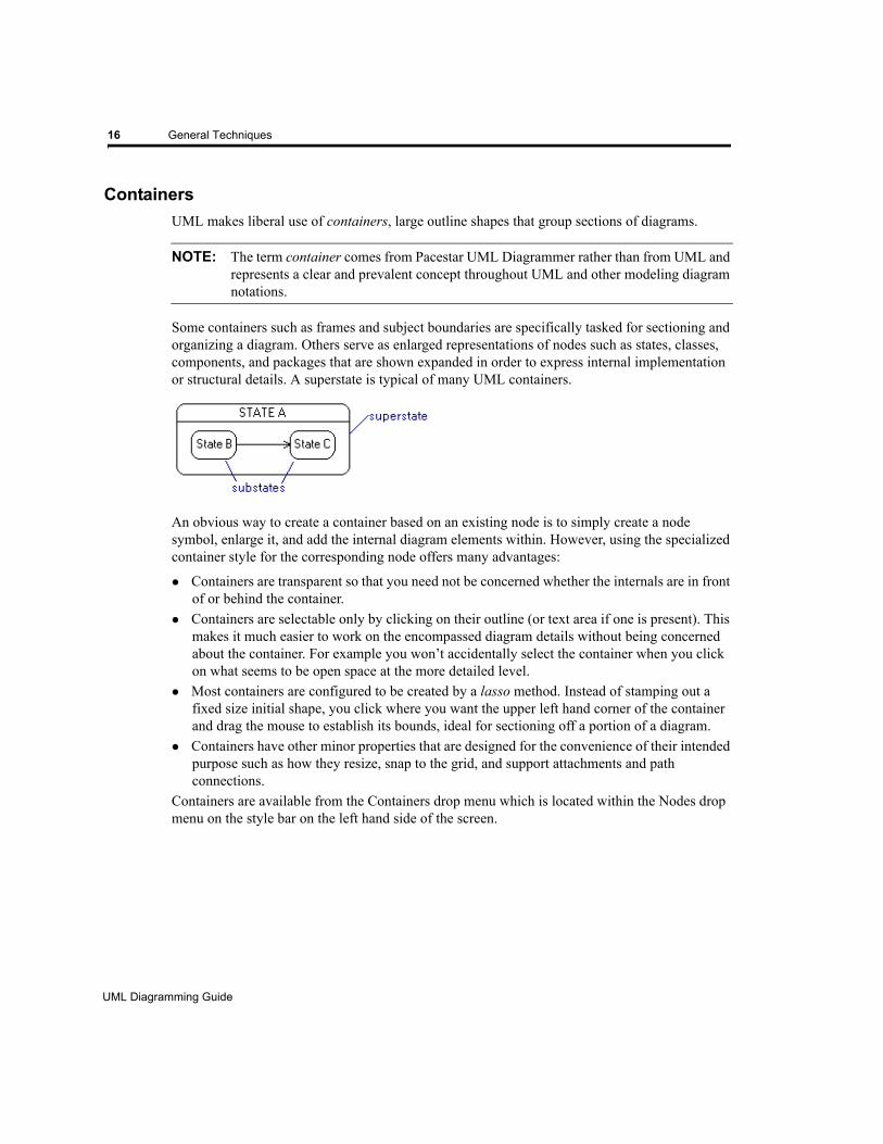
ContainersUML makes liberal use of containers, large outline shapes that group sections of diagrams.
NOTE: The term container comes from Pacestar UML Diagrammer rather than from UML and represents a clear and prevalent concept throughout UML and other modeling diagram notations.
Some containers such as frames and subject boundaries are specifically tasked for sectioning and organizing a diagram. Others serve as enlarged representations of nodes such as states, classes, components, and packages that are shown expanded in order to express internal implementation or structural details. A superstate is typical of many UML containers.
An obvious way to create a container based on an existing node is to simply create a node symbol, enlarge it, and add the internal diagram elements within. However, using the specialized container style for the corresponding node offers many advantages:
Containers are transparent so that you need not be concerned whether the internals are in front of or behind the container.Containers are selectable only by clicking on their outline (or text area if one is present). This makes it much easier to work on the encompassed diagram details without being concerned about the container. For example you won’t accidentally select the container when you click on what seems to be open space at the more detailed level.Most containers are configured to be created by a lasso method. Instead of stamping out a fixed size initial shape, you click where you want the upper left hand corner of the container and drag the mouse to establish its bounds, ideal for sectioning off a portion of a diagram.Containers have other minor properties that are designed for the convenience of their intended purpose such as how they resize, snap to the grid, and support attachments and path connections.
Containers are available from the Containers drop menu which is located within the Nodes drop menu on the style bar on the left hand side of the screen.
UML Diagramming Guide
EDGE Diagrammer User’s Guide - Beta Version
Page 16 of 96
Last Modified May 18, 2009 5:39 pm
Filename: S:\UFLOW\UMLDOC\UML Diagramming Guide.fm
General Techniques 17
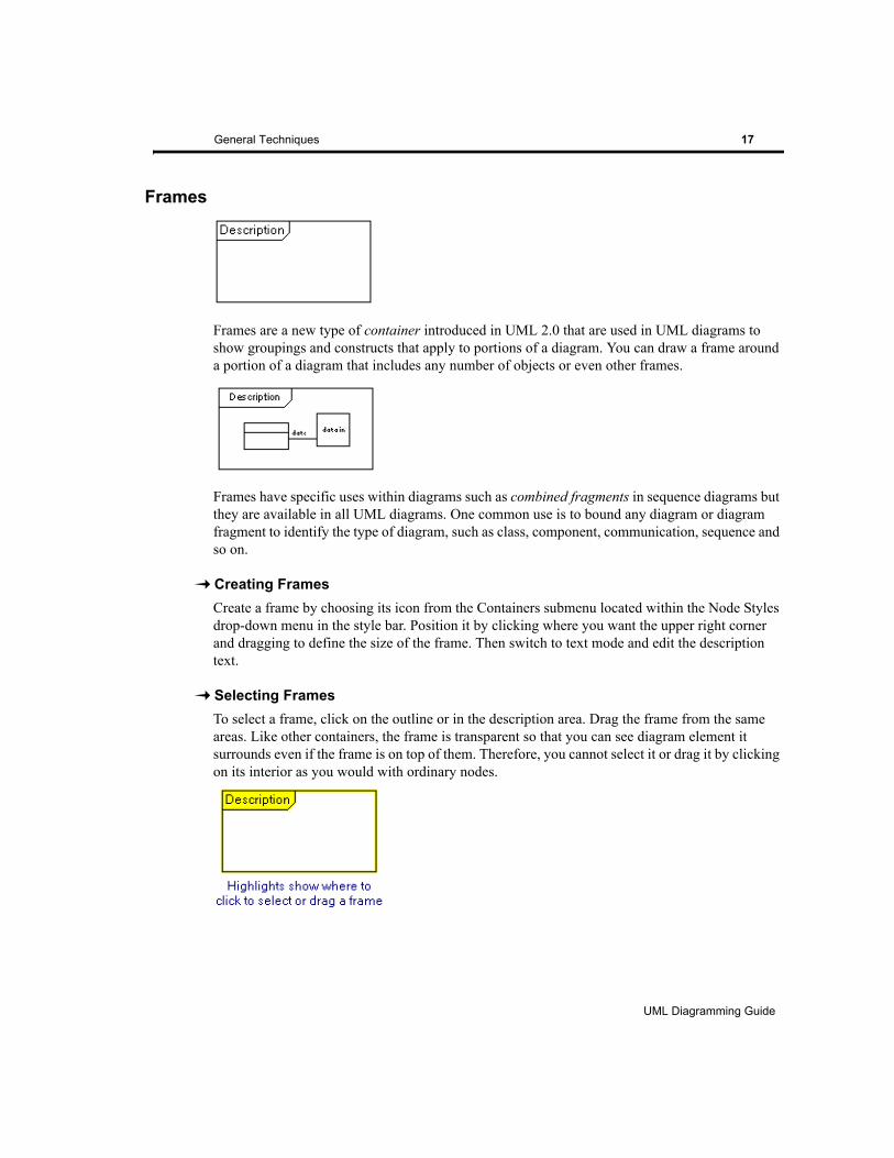
Frames
Frames are a new type of container introduced in UML 2.0 that are used in UML diagrams to show groupings and constructs that apply to portions of a diagram. You can draw a frame around a portion of a diagram that includes any number of objects or even other frames.
Frames have specific uses within diagrams such as combined fragments in sequence diagrams but they are available in all UML diagrams. One common use is to bound any diagram or diagram fragment to identify the type of diagram, such as class, component, communication, sequence and so on.
Creating FramesCreate a frame by choosing its icon from the Containers submenu located within the Node Styles drop-down menu in the style bar. Position it by clicking where you want the upper right corner and dragging to define the size of the frame. Then switch to text mode and edit the description text.
Selecting FramesTo select a frame, click on the outline or in the description area. Drag the frame from the same areas. Like other containers, the frame is transparent so that you can see diagram element it surrounds even if the frame is on top of them. Therefore, you cannot select it or drag it by clicking on its interior as you would with ordinary nodes.
UML Diagramming Guide
EDGE Diagrammer User’s Guide
Page 17 of 96
Last Modified May 18, 2009 5:39 pm
Filename: S:\UFLOW\UMLDOC\UML Diagramming Guide.fm
18 General Techniques
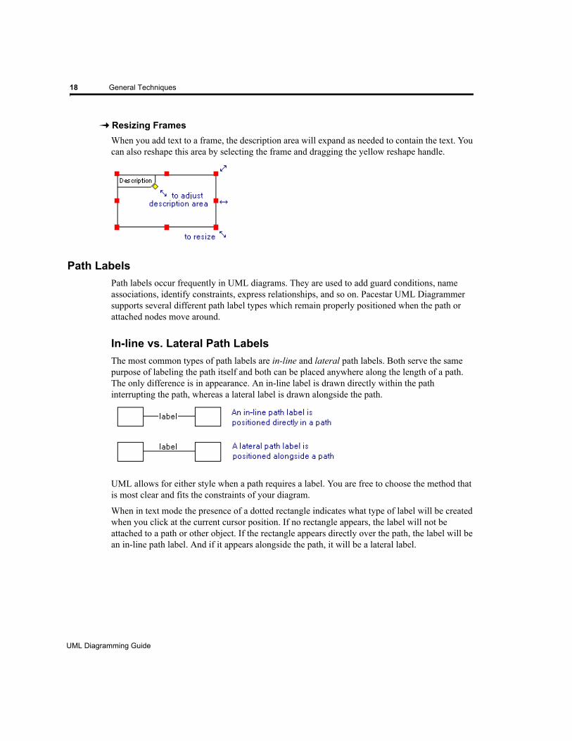
Resizing FramesWhen you add text to a frame, the description area will expand as needed to contain the text. You can also reshape this area by selecting the frame and dragging the yellow reshape handle.
Path LabelsPath labels occur frequently in UML diagrams. They are used to add guard conditions, name associations, identify constraints, express relationships, and so on. Pacestar UML Diagrammer supports several different path label types which remain properly positioned when the path or attached nodes move around.
In-line vs. Lateral Path LabelsThe most common types of path labels are in-line and lateral path labels. Both serve the same purpose of labeling the path itself and both can be placed anywhere along the length of a path. The only difference is in appearance. An in-line label is drawn directly within the path interrupting the path, whereas a lateral label is drawn alongside the path.
UML allows for either style when a path requires a label. You are free to choose the method that is most clear and fits the constraints of your diagram.
When in text mode the presence of a dotted rectangle indicates what type of label will be created when you click at the current cursor position. If no rectangle appears, the label will not be attached to a path or other object. If the rectangle appears directly over the path, the label will be an in-line path label. And if it appears alongside the path, it will be a lateral label.
UML Diagramming Guide
EDGE Diagrammer User’s Guide - Beta Version
Page 18 of 96
Last Modified May 18, 2009 5:39 pm
Filename: S:\UFLOW\UMLDOC\UML Diagramming Guide.fm
General Techniques 19
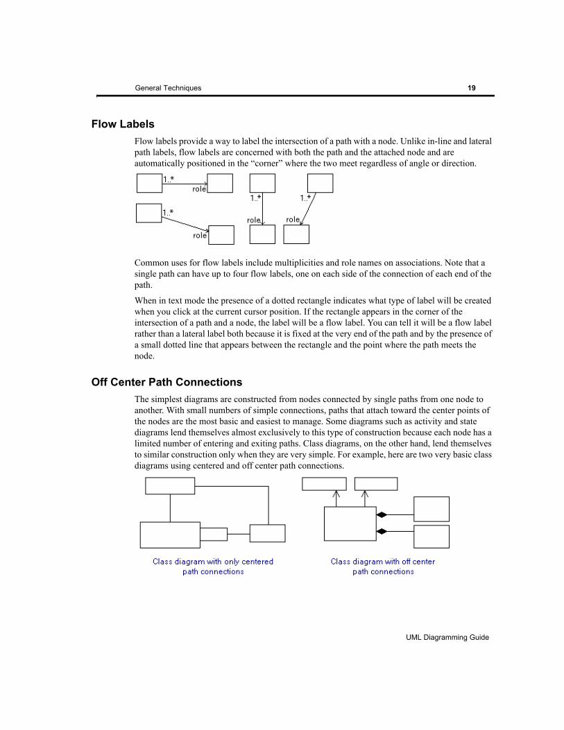
Flow LabelsFlow labels provide a way to label the intersection of a path with a node. Unlike in-line and lateral path labels, flow labels are concerned with both the path and the attached node and are automatically positioned in the “corner” where the two meet regardless of angle or direction.
Common uses for flow labels include multiplicities and role names on associations. Note that a single path can have up to four flow labels, one on each side of the connection of each end of the path.
When in text mode the presence of a dotted rectangle indicates what type of label will be created when you click at the current cursor position. If the rectangle appears in the corner of the intersection of a path and a node, the label will be a flow label. You can tell it will be a flow label rather than a lateral label both because it is fixed at the very end of the path and by the presence of a small dotted line that appears between the rectangle and the point where the path meets the node.
Off Center Path ConnectionsThe simplest diagrams are constructed from nodes connected by single paths from one node to another. With small numbers of simple connections, paths that attach toward the center points of the nodes are the most basic and easiest to manage. Some diagrams such as activity and state diagrams lend themselves almost exclusively to this type of construction because each node has a limited number of entering and exiting paths. Class diagrams, on the other hand, lend themselves to similar construction only when they are very simple. For example, here are two very basic class diagrams using centered and off center path connections.
UML Diagramming Guide
EDGE Diagrammer User’s Guide
Page 19 of 96
Last Modified May 18, 2009 5:39 pm
Filename: S:\UFLOW\UMLDOC\UML Diagramming Guide.fm

20 General Techniques
There are two ways to control which of these connection models are used to configure new path connections. You will find this information under Attach Modes in the main user guide, but we’ll summarize it here as well for convenience.
If most of your connections will be centered with an occasional off center connection, you can switch back and forth simply by holding down the SHIFT key as you make the connection. For example, if you are attaching a path between two nodes and wish it to originate from the point on the first node where you click (as opposed to the center of the node), you simply hold the SHIFT key as you click to position the start of the path on the first node. This method of connecting a path is called Click Point. Note that while in connect mode, the status bar will remind you that holding SHIFT will result in Click Point attachments. Also note that you can route the path from the origin point on the first node to the terminating point on the second node by clicking at any number of intermediate points on the diagram in between.
You can also switch attach modes so that holding down the SHIFT key is no longer necessary. If your diagram contains many off center attachments, this is the more practical way to proceed. In fact, switching the attach mode to Click Point is often the first step in beginning a non-trivial class diagram. The attach mode can be changed by selecting one of the modes listed under Attach which is available in the Paths menu. Once in Click Point attach mode, SHIFT switches back to centers on a case-by-case basis.
Path TreesSome UML diagrams require more than simple node-to-node paths. You can create any conceivable circuit of paths by connecting portions of paths to one another. The most common arrangement is a “tree”. A tree minimizes the number of paths that connect to a common node. A good example is an inheritance relationship which consists of a large number of classes that derive from a base class, each depicted by a generalization path to the base class node.
UML Diagramming Guide
EDGE Diagrammer User’s Guide - Beta Version
Page 20 of 96
Last Modified May 18, 2009 5:39 pm
Filename: S:\UFLOW\UMLDOC\UML Diagramming Guide.fm
General Techniques 21
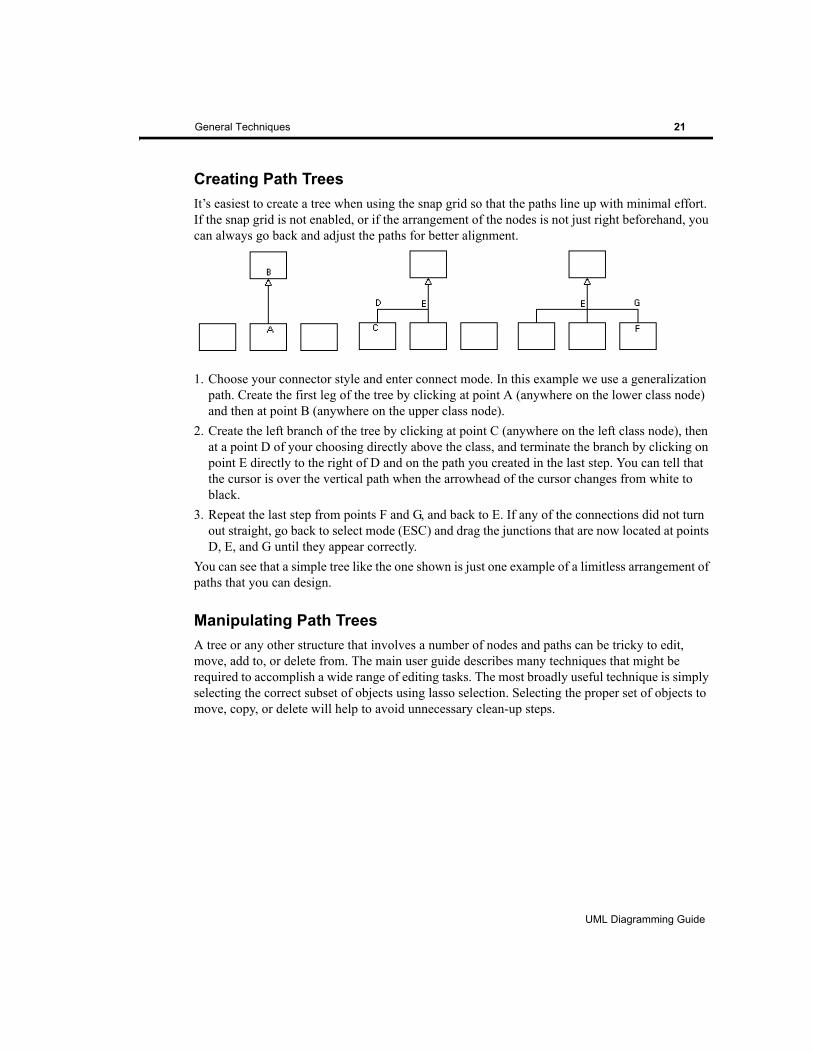
Creating Path TreesIt’s easiest to create a tree when using the snap grid so that the paths line up with minimal effort. If the snap grid is not enabled, or if the arrangement of the nodes is not just right beforehand, you can always go back and adjust the paths for better alignment.
1. Choose your connector style and enter connect mode. In this example we use a generalization path. Create the first leg of the tree by clicking at point A (anywhere on the lower class node) and then at point B (anywhere on the upper class node).
2. Create the left branch of the tree by clicking at point C (anywhere on the left class node), then at a point D of your choosing directly above the class, and terminate the branch by clicking on point E directly to the right of D and on the path you created in the last step. You can tell that the cursor is over the vertical path when the arrowhead of the cursor changes from white to black.
3. Repeat the last step from points F and G, and back to E. If any of the connections did not turn out straight, go back to select mode (ESC) and drag the junctions that are now located at points D, E, and G until they appear correctly.
You can see that a simple tree like the one shown is just one example of a limitless arrangement of paths that you can design.
Manipulating Path TreesA tree or any other structure that involves a number of nodes and paths can be tricky to edit, move, add to, or delete from. The main user guide describes many techniques that might be required to accomplish a wide range of editing tasks. The most broadly useful technique is simply selecting the correct subset of objects using lasso selection. Selecting the proper set of objects to move, copy, or delete will help to avoid unnecessary clean-up steps.
UML Diagramming Guide
EDGE Diagrammer User’s Guide
Page 21 of 96
Last Modified May 18, 2009 5:39 pm
Filename: S:\UFLOW\UMLDOC\UML Diagramming Guide.fm
22 General Techniques
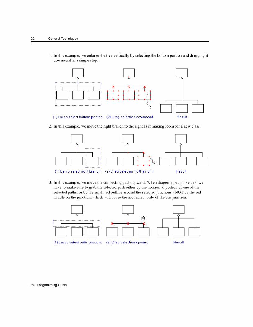
1. In this example, we enlarge the tree vertically by selecting the bottom portion and dragging it downward in a single step.
2. In this example, we move the right branch to the right as if making room for a new class.
3. In this example, we move the connecting paths upward. When dragging paths like this, we have to make sure to grab the selected path either by the horizontal portion of one of the selected paths, or by the small red outline around the selected junctions - NOT by the red handle on the junctions which will cause the movement only of the one junction.
UML Diagramming Guide
EDGE Diagrammer User’s Guide - Beta Version
Page 22 of 96
Last Modified May 18, 2009 5:39 pm
Filename: S:\UFLOW\UMLDOC\UML Diagramming Guide.fm

General Techniques 23
Node Symbols Containing Internal IconsSeveral node symbols contain internal icons (usually in the upper right or lower right corners) to add clarity or to further specify their role in the diagram. A number of these symbols are shown here:
The icons are defined as part of the node styles. The line width and color they are drawn with matches the line width of the border of the style and cannot be modified independently. The spacing between the icon and the edges of the shape matches the text border and can be controlled (currently only per-diagram) by adjusting the text margin spacing located in the Diagram Properties dialog box.
Also note that in most cases the internal icon overlaps the text area of the symbol. This means that your text may collide with the symbol. You can avoid this manually by adjusting the size of the symbol, the text justification, or padding the text with extra spaces.
Extensions and Nonstandard SymbolsThe tool does not force you to adhere to the strict definition of UML. Instead it allows you to extend the language as you see fit for your own needs. We leave it up to you and your best judgement to determine whether to use custom extensions and notation.
UML does not preclude adding symbols that are not a part of the UML specification to your UML diagrams for the purpose of enhancing or adorning your diagrams. Each of our UML diagram templates include a category named “Nonstandard” that contains a number of shapes that may be useful in your diagrams but are not included in UML and have no defined usage. They are included for you to use (or not use) at your own discretion.
The Nonstandard category of symbols are a subset of the larger collection of symbols included with the product in the symbol galleries. The symbol galleries contain a variety of addition shapes and symbols such as obsolete symbols from older UML standards, more nonstandard UML symbols, flowcharting symbols, and other miscellaneous shapes. To add a symbol or icon from the symbol galleries use the Insert Node/Icon feature from the Nodes menu (also available by default as a toolbar button).
Similarly, you may on occasion want to add imported clipart or graphics to your diagrams. This is fully supported by the tool and is commonly practiced with UML. In Use Case diagrams for example, many designers prefer to substitute clipart or icons for actors to increase clarity or add
UML Diagramming Guide
EDGE Diagrammer User’s Guide
Page 23 of 96
Last Modified May 18, 2009 5:39 pm
Filename: S:\UFLOW\UMLDOC\UML Diagramming Guide.fm
24 General Techniques
emphasis. To insert a graphic from a file, use the Insert Graphic feature from the Nodes menu (also available by default as a toolbar button).
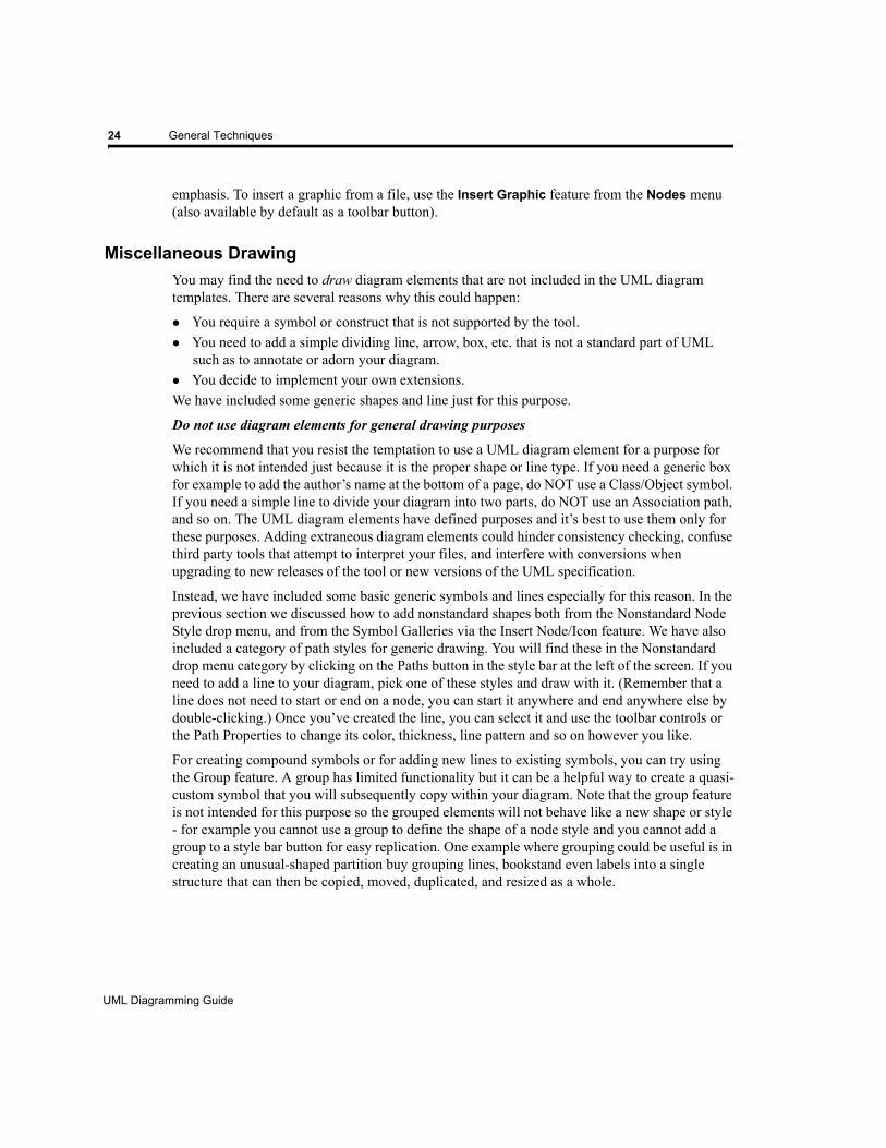
Miscellaneous DrawingYou may find the need to draw diagram elements that are not included in the UML diagram templates. There are several reasons why this could happen:
You require a symbol or construct that is not supported by the tool.You need to add a simple dividing line, arrow, box, etc. that is not a standard part of UML such as to annotate or adorn your diagram.You decide to implement your own extensions.
We have included some generic shapes and line just for this purpose.
Do not use diagram elements for general drawing purposes
We recommend that you resist the temptation to use a UML diagram element for a purpose for which it is not intended just because it is the proper shape or line type. If you need a generic box for example to add the author’s name at the bottom of a page, do NOT use a Class/Object symbol. If you need a simple line to divide your diagram into two parts, do NOT use an Association path, and so on. The UML diagram elements have defined purposes and it’s best to use them only for these purposes. Adding extraneous diagram elements could hinder consistency checking, confuse third party tools that attempt to interpret your files, and interfere with conversions when upgrading to new releases of the tool or new versions of the UML specification.
Instead, we have included some basic generic symbols and lines especially for this reason. In the previous section we discussed how to add nonstandard shapes both from the Nonstandard Node Style drop menu, and from the Symbol Galleries via the Insert Node/Icon feature. We have also included a category of path styles for generic drawing. You will find these in the Nonstandard drop menu category by clicking on the Paths button in the style bar at the left of the screen. If you need to add a line to your diagram, pick one of these styles and draw with it. (Remember that a line does not need to start or end on a node, you can start it anywhere and end anywhere else by double-clicking.) Once you’ve created the line, you can select it and use the toolbar controls or the Path Properties to change its color, thickness, line pattern and so on however you like.
For creating compound symbols or for adding new lines to existing symbols, you can try using the Group feature. A group has limited functionality but it can be a helpful way to create a quasi-custom symbol that you will subsequently copy within your diagram. Note that the group feature is not intended for this purpose so the grouped elements will not behave like a new shape or style - for example you cannot use a group to define the shape of a node style and you cannot add a group to a style bar button for easy replication. One example where grouping could be useful is in creating an unusual-shaped partition buy grouping lines, bookstand even labels into a single structure that can then be copied, moved, duplicated, and resized as a whole.
UML Diagramming Guide
EDGE Diagrammer User’s Guide - Beta Version
Page 24 of 96
Last Modified May 18, 2009 5:39 pm
Filename: S:\UFLOW\UMLDOC\UML Diagramming Guide.fm
CHAPTER2 ACTIVITY DIAGRAMS
This section describes diagramming techniques that are primarily applicable to Activity Diagrams.
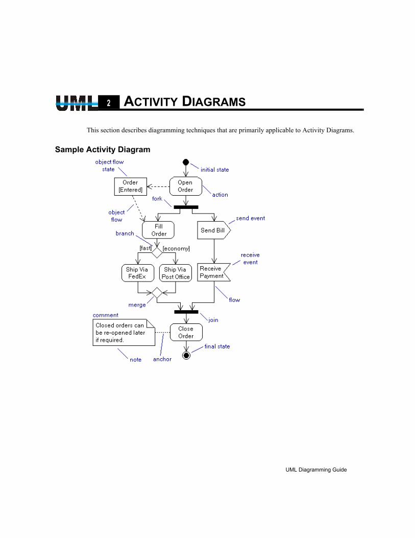
Sample Activity Diagram
UML Diagramming Guide
EDGE Diagrammer User’s Guide
Page 25 of 96
Last Modified May 18, 2009 5:39 pm
Filename: S:\UFLOW\UMLDOC\UML Diagramming Guide.fm
26 Activity Diagrams
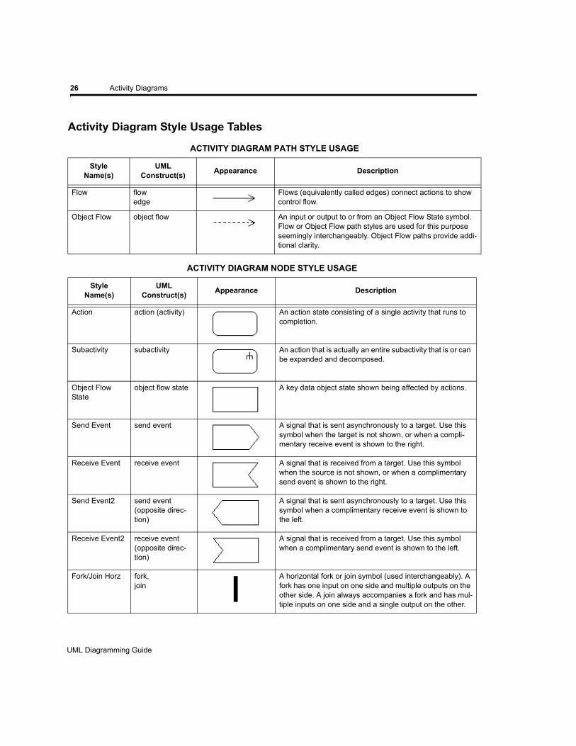
Activity Diagram Style Usage Tables
ACTIVITY DIAGRAM PATH STYLE USAGE
StyleName(s)
UML Construct(s) Appearance Description
Flow flowedge
Flows (equivalently called edges) connect actions to show control flow.
Object Flow object flow An input or output to or from an Object Flow State symbol. Flow or Object Flow path styles are used for this purpose seemingly interchangeably. Object Flow paths provide addi-tional clarity.
ACTIVITY DIAGRAM NODE STYLE USAGE
StyleName(s)
UML Construct(s) Appearance Description
Action action (activity) An action state consisting of a single activity that runs to completion.
Subactivity subactivity An action that is actually an entire subactivity that is or can be expanded and decomposed.
Object Flow State
object flow state A key data object state shown being affected by actions.
Send Event send event A signal that is sent asynchronously to a target. Use this symbol when the target is not shown, or when a compli-mentary receive event is shown to the right.
Receive Event receive event A signal that is received from a target. Use this symbol when the source is not shown, or when a complimentary send event is shown to the right.
Send Event2 send event (opposite direc-tion)
A signal that is sent asynchronously to a target. Use this symbol when a complimentary receive event is shown to the left.
Receive Event2 receive event(opposite direc-tion)
A signal that is received from a target. Use this symbol when a complimentary send event is shown to the left.
Fork/Join Horz fork,join
A horizontal fork or join symbol (used interchangeably). A fork has one input on one side and multiple outputs on the other side. A join always accompanies a fork and has mul-tiple inputs on one side and a single output on the other.
UML Diagramming Guide
EDGE Diagrammer User’s Guide - Beta Version
Page 26 of 96
Last Modified May 18, 2009 5:39 pm
Filename: S:\UFLOW\UMLDOC\UML Diagramming Guide.fm
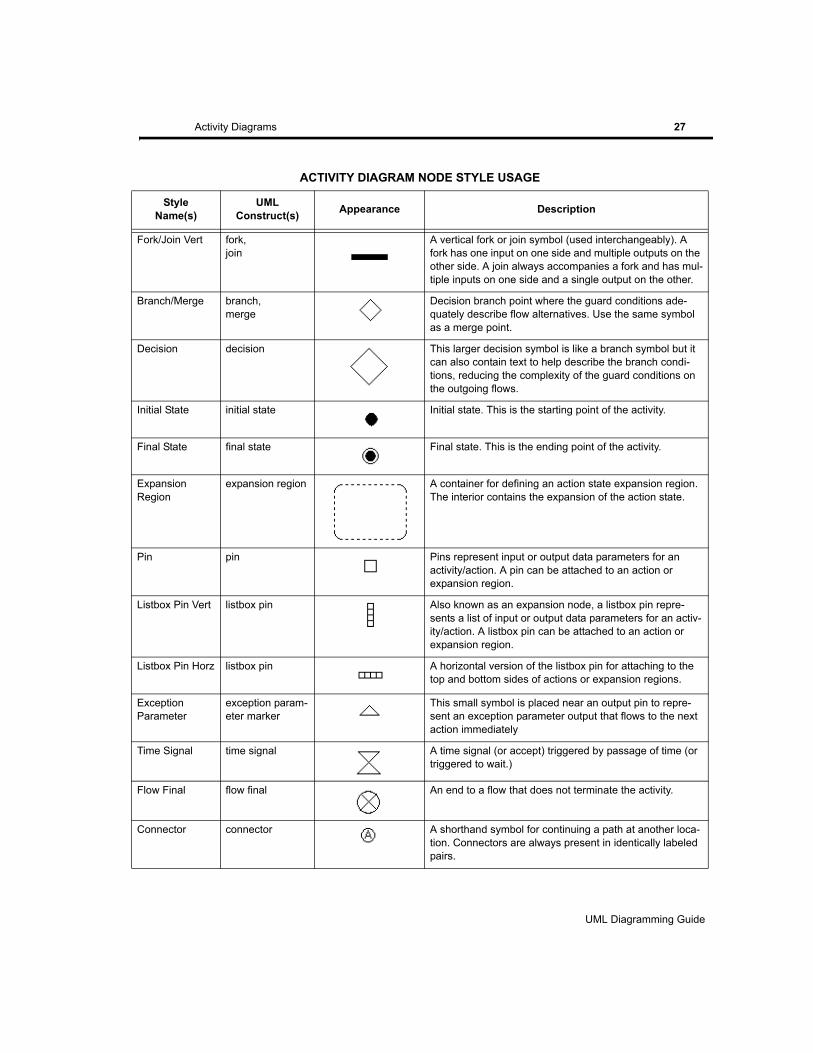
Activity Diagrams 27
Fork/Join Vert fork,join
A vertical fork or join symbol (used interchangeably). A fork has one input on one side and multiple outputs on the other side. A join always accompanies a fork and has mul-tiple inputs on one side and a single output on the other.
Branch/Merge branch,merge
Decision branch point where the guard conditions ade-quately describe flow alternatives. Use the same symbol as a merge point.
Decision decision This larger decision symbol is like a branch symbol but it can also contain text to help describe the branch condi-tions, reducing the complexity of the guard conditions on the outgoing flows.
Initial State initial state Initial state. This is the starting point of the activity.
Final State final state Final state. This is the ending point of the activity.
Expansion Region
expansion region A container for defining an action state expansion region. The interior contains the expansion of the action state.
Pin pin Pins represent input or output data parameters for an activity/action. A pin can be attached to an action or expansion region.
Listbox Pin Vert listbox pin Also known as an expansion node, a listbox pin repre-sents a list of input or output data parameters for an activ-ity/action. A listbox pin can be attached to an action or expansion region.
Listbox Pin Horz listbox pin A horizontal version of the listbox pin for attaching to the top and bottom sides of actions or expansion regions.
Exception Parameter
exception param-eter marker
This small symbol is placed near an output pin to repre-sent an exception parameter output that flows to the next action immediately
Time Signal time signal A time signal (or accept) triggered by passage of time (or triggered to wait.)
Flow Final flow final An end to a flow that does not terminate the activity.
Connector connector A shorthand symbol for continuing a path at another loca-tion. Connectors are always present in identically labeled pairs.
ACTIVITY DIAGRAM NODE STYLE USAGE
StyleName(s)
UML Construct(s) Appearance Description
UML Diagramming Guide
EDGE Diagrammer User’s Guide
Page 27 of 96
Last Modified May 18, 2009 5:39 pm
Filename: S:\UFLOW\UMLDOC\UML Diagramming Guide.fm
28 Activity Diagrams
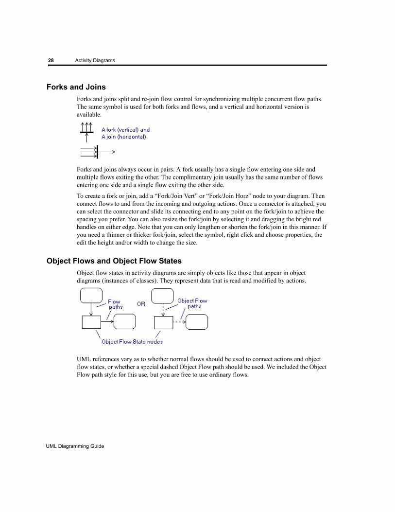
Forks and JoinsForks and joins split and re-join flow control for synchronizing multiple concurrent flow paths. The same symbol is used for both forks and flows, and a vertical and horizontal version is available.
Forks and joins always occur in pairs. A fork usually has a single flow entering one side and multiple flows exiting the other. The complimentary join usually has the same number of flows entering one side and a single flow exiting the other side.
To create a fork or join, add a “Fork/Join Vert” or “Fork/Join Horz” node to your diagram. Then connect flows to and from the incoming and outgoing actions. Once a connector is attached, you can select the connector and slide its connecting end to any point on the fork/join to achieve the spacing you prefer. You can also resize the fork/join by selecting it and dragging the bright red handles on either edge. Note that you can only lengthen or shorten the fork/join in this manner. If you need a thinner or thicker fork/join, select the symbol, right click and choose properties, the edit the height and/or width to change the size.
Object Flows and Object Flow StatesObject flow states in activity diagrams are simply objects like those that appear in object diagrams (instances of classes). They represent data that is read and modified by actions.
UML references vary as to whether normal flows should be used to connect actions and object flow states, or whether a special dashed Object Flow path should be used. We included the Object Flow path style for this use, but you are free to use ordinary flows.
UML Diagramming Guide
EDGE Diagrammer User’s Guide - Beta Version
Page 28 of 96
Last Modified May 18, 2009 5:39 pm
Filename: S:\UFLOW\UMLDOC\UML Diagramming Guide.fm
Activity Diagrams 29
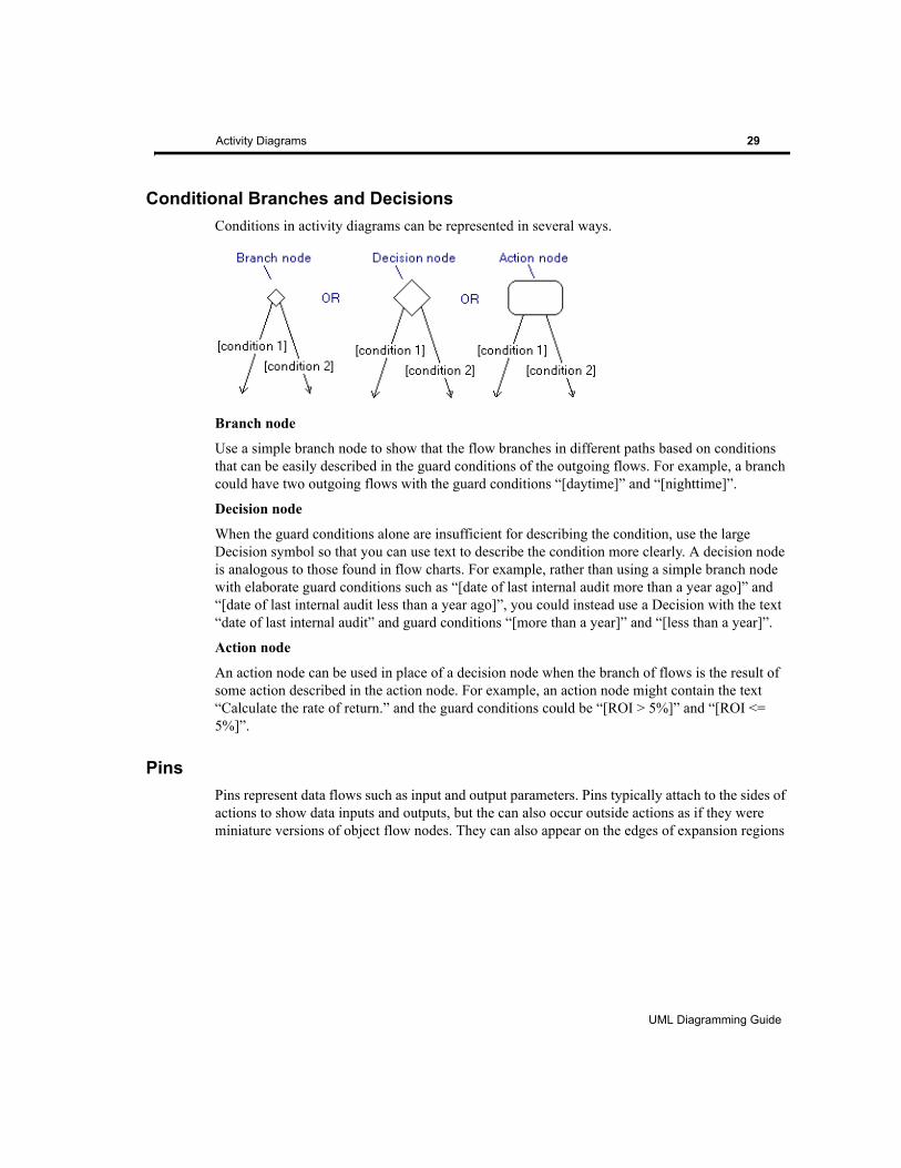
Conditional Branches and DecisionsConditions in activity diagrams can be represented in several ways.
Branch node
Use a simple branch node to show that the flow branches in different paths based on conditions that can be easily described in the guard conditions of the outgoing flows. For example, a branch could have two outgoing flows with the guard conditions “[daytime]” and “[nighttime]”.
Decision node
When the guard conditions alone are insufficient for describing the condition, use the large Decision symbol so that you can use text to describe the condition more clearly. A decision node is analogous to those found in flow charts. For example, rather than using a simple branch node with elaborate guard conditions such as “[date of last internal audit more than a year ago]” and “[date of last internal audit less than a year ago]”, you could instead use a Decision with the text “date of last internal audit” and guard conditions “[more than a year]” and “[less than a year]”.
Action node
An action node can be used in place of a decision node when the branch of flows is the result of some action described in the action node. For example, an action node might contain the text “Calculate the rate of return.” and the guard conditions could be “[ROI > 5%]” and “[ROI <= 5%]”.
PinsPins represent data flows such as input and output parameters. Pins typically attach to the sides of actions to show data inputs and outputs, but the can also occur outside actions as if they were miniature versions of object flow nodes. They can also appear on the edges of expansion regions
UML Diagramming Guide
EDGE Diagrammer User’s Guide
Page 29 of 96
Last Modified May 18, 2009 5:39 pm
Filename: S:\UFLOW\UMLDOC\UML Diagramming Guide.fm
30 Activity Diagrams
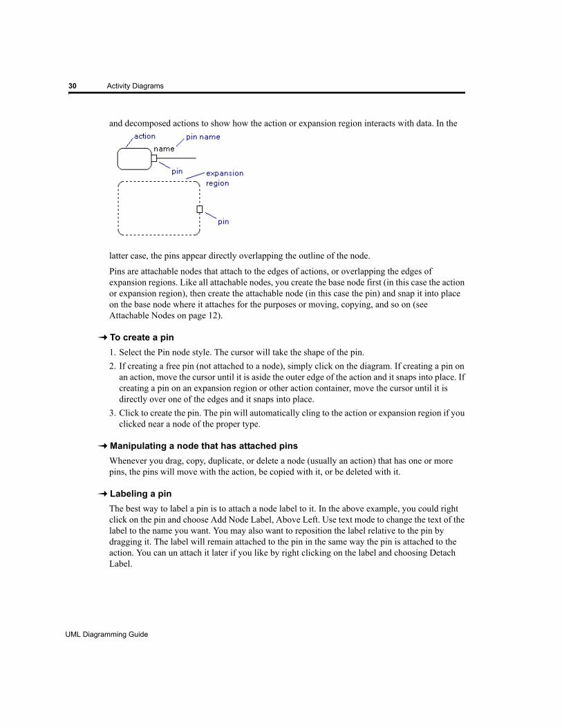
and decomposed actions to show how the action or expansion region interacts with data. In the
latter case, the pins appear directly overlapping the outline of the node.
Pins are attachable nodes that attach to the edges of actions, or overlapping the edges of expansion regions. Like all attachable nodes, you create the base node first (in this case the action or expansion region), then create the attachable node (in this case the pin) and snap it into place on the base node where it attaches for the purposes or moving, copying, and so on (see Attachable Nodes on page 12).
To create a pin 1. Select the Pin node style. The cursor will take the shape of the pin.2. If creating a free pin (not attached to a node), simply click on the diagram. If creating a pin on
an action, move the cursor until it is aside the outer edge of the action and it snaps into place. If creating a pin on an expansion region or other action container, move the cursor until it is directly over one of the edges and it snaps into place.
3. Click to create the pin. The pin will automatically cling to the action or expansion region if you clicked near a node of the proper type.
Manipulating a node that has attached pinsWhenever you drag, copy, duplicate, or delete a node (usually an action) that has one or more pins, the pins will move with the action, be copied with it, or be deleted with it.
Labeling a pinThe best way to label a pin is to attach a node label to it. In the above example, you could right click on the pin and choose Add Node Label, Above Left. Use text mode to change the text of the label to the name you want. You may also want to reposition the label relative to the pin by dragging it. The label will remain attached to the pin in the same way the pin is attached to the action. You can un attach it later if you like by right clicking on the label and choosing Detach Label.
UML Diagramming Guide
EDGE Diagrammer User’s Guide - Beta Version
Page 30 of 96
Last Modified May 18, 2009 5:39 pm
Filename: S:\UFLOW\UMLDOC\UML Diagramming Guide.fm
Activity Diagrams 31
Detaching a PinTo detach a pin from an action, simply drag it away from the action node. Alternately, right click on the pin and select the Detach command.
Repositioning a pinYou can drag a pin to reposition it on the action or detach it. Dragging to reposition the pin works similar to creating the pin. You can choose to move it free of the action, attach it to a side of an action, or attach it to an expansion region.
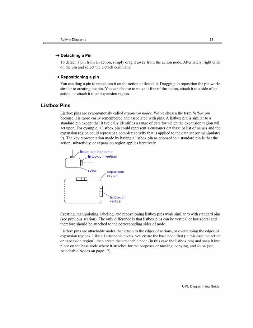
Listbox PinsListbox pins are synonymously called expansion nodes. We’ve chosen the term listbox pin because it is more easily remembered and associated with pins. A listbox pin is similar to a standard pin except that it typically identifies a range of data for which the expansion region will act upon. For example, a listbox pin could represent a customer database or list of names and the expansion region could represent a complex activity that is applied to the data set (or manipulates it). The key representation made by having a listbox pin as opposed to a standard pin is that the action, subactivity, or expansion region applies iteratively.
Creating, manipulating, labeling, and repositioning listbox pins work similar to with standard pins (see previous section). The only difference is that listbox pins can be vertical or horizontal and therefore should be attached to the corresponding sides of node.
Listbox pins are attachable nodes that attach to the edges of actions, or overlapping the edges of expansion regions. Like all attachable nodes, you create the base node first (in this case the action or expansion region), then create the attachable node (in this case the listbox pin) and snap it into place on the base node where it attaches for the purposes or moving, copying, and so on (see Attachable Nodes on page 12).
UML Diagramming Guide
EDGE Diagrammer User’s Guide
Page 31 of 96
Last Modified May 18, 2009 5:39 pm
Filename: S:\UFLOW\UMLDOC\UML Diagramming Guide.fm
32 Activity Diagrams
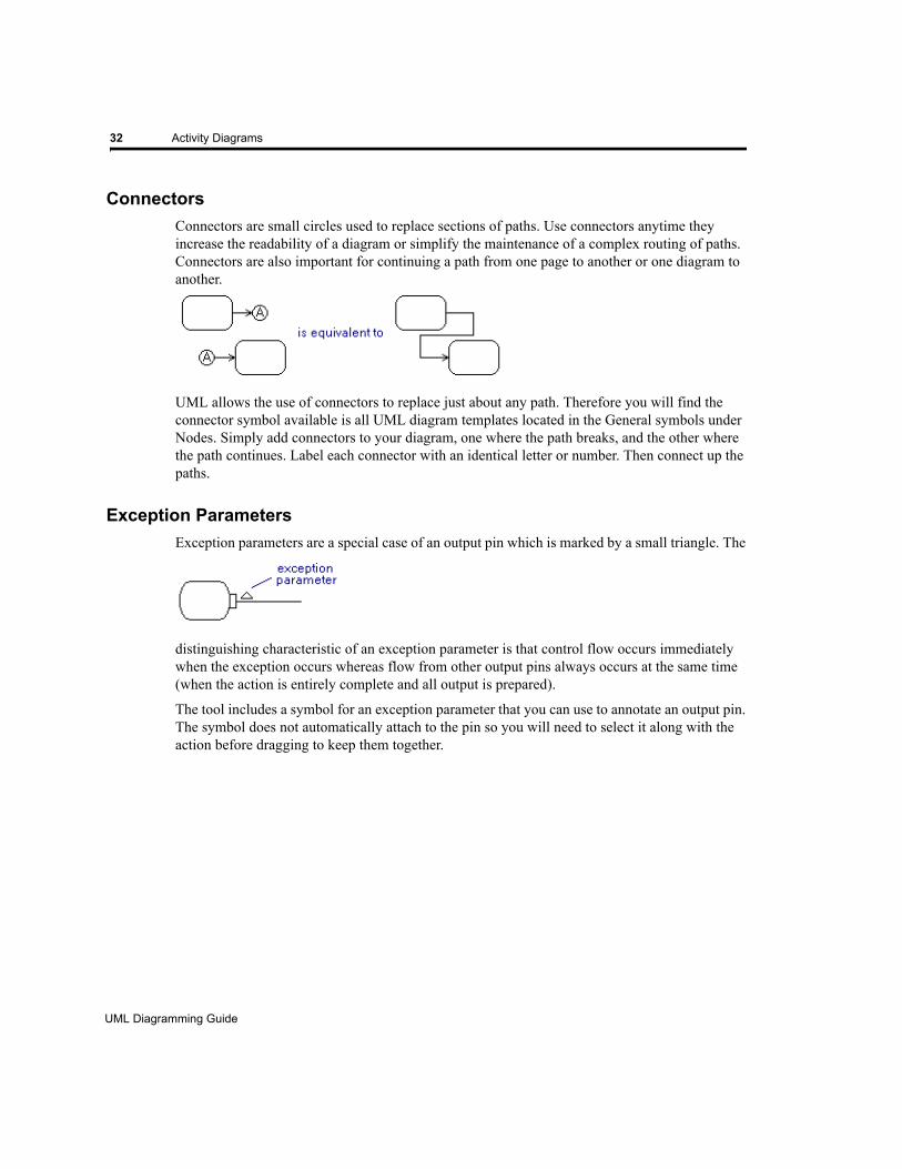
ConnectorsConnectors are small circles used to replace sections of paths. Use connectors anytime they increase the readability of a diagram or simplify the maintenance of a complex routing of paths. Connectors are also important for continuing a path from one page to another or one diagram to another.
UML allows the use of connectors to replace just about any path. Therefore you will find the connector symbol available is all UML diagram templates located in the General symbols under Nodes. Simply add connectors to your diagram, one where the path breaks, and the other where the path continues. Label each connector with an identical letter or number. Then connect up the paths.
Exception ParametersException parameters are a special case of an output pin which is marked by a small triangle. The
distinguishing characteristic of an exception parameter is that control flow occurs immediately when the exception occurs whereas flow from other output pins always occurs at the same time (when the action is entirely complete and all output is prepared).
The tool includes a symbol for an exception parameter that you can use to annotate an output pin. The symbol does not automatically attach to the pin so you will need to select it along with the action before dragging to keep them together.
UML Diagramming Guide
EDGE Diagrammer User’s Guide - Beta Version
Page 32 of 96
Last Modified May 18, 2009 5:39 pm
Filename: S:\UFLOW\UMLDOC\UML Diagramming Guide.fm

Activity Diagrams 33
Interruptible Activity RegionsAn interruptible activity region is marked by a dashed rounded rectangle (a container). Use the node style “Interruptible Region” to enclose the interruptible portion of the activity diagram. You can use a jagged flow path to indicate the flow that is followed when the interrupt occurs within the region.
The jagged flow is not a special flow style, but rather a flow that is created in three segments. For example, select the Path path style, click at A, click at B, click at C, then double click at D to create the above jagged flow symbol.
UML Diagramming Guide
EDGE Diagrammer User’s Guide
Page 33 of 96
Last Modified May 18, 2009 5:39 pm
Filename: S:\UFLOW\UMLDOC\UML Diagramming Guide.fm

34 Activity Diagrams
UML Diagramming Guide
EDGE Diagrammer User’s Guide - Beta Version
Page 34 of 96
Last Modified May 18, 2009 5:39 pm
Filename: S:\UFLOW\UMLDOC\UML Diagramming Guide.fm
CHAPTER3 CLASS/OBJECT DIAGRAMS
This section describes diagramming techniques that are primarily applicable to Class/Object Diagrams. Techniques described elsewhere for handling messages, ports, interfaces, packages, and partitions are also useful when working with class diagrams.
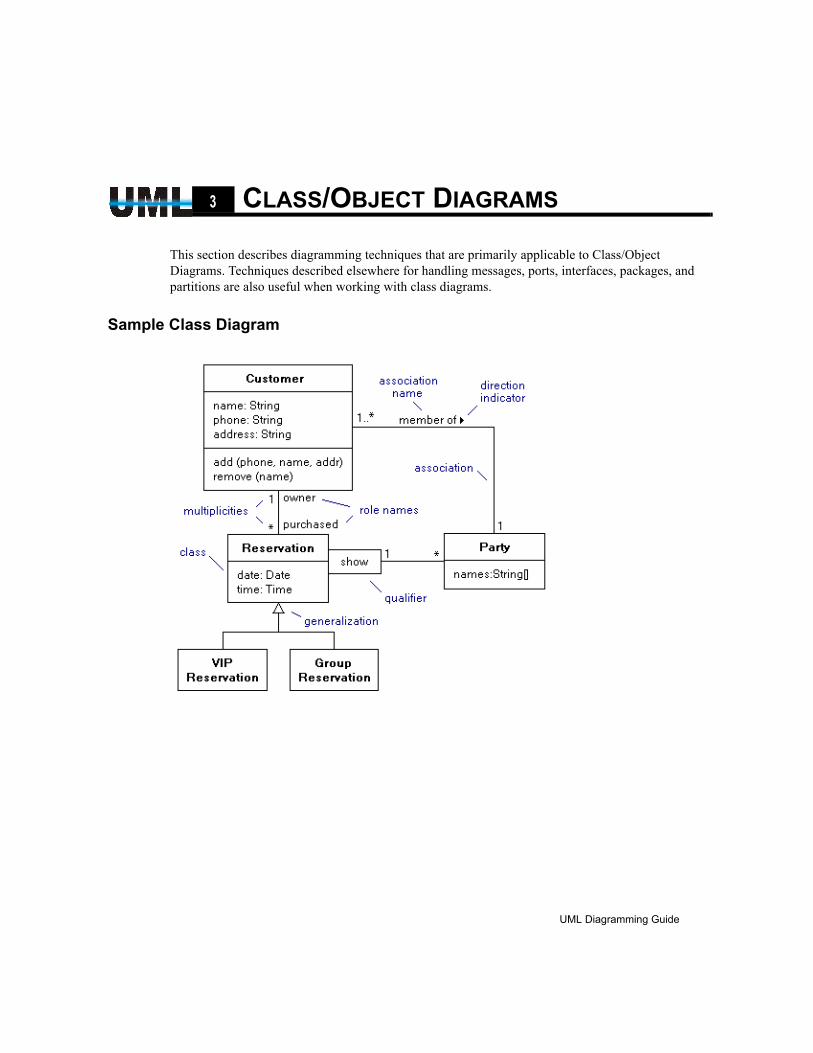
Sample Class Diagram
UML Diagramming Guide
EDGE Diagrammer User’s Guide
Page 35 of 96
Last Modified May 18, 2009 5:39 pm
Filename: S:\UFLOW\UMLDOC\UML Diagramming Guide.fm

36 Class/Object Diagrams
Class/Object Diagram Style Usage Tables
CLASS/OBJECT DIAGRAM PATH STYLE USAGE
StyleName(s)
UML Construct(s) Appearance Description
Association association A relationship between classes or objects. An association without arrows shows either bidirectional navigability, or simply does not show the navigability.
Directional Association
directionalassociation
A association between classes that is navigable in one direction.
Bidirectional Association
bidirectionalassociation
A association between classes that is navigable in both directions.
unnavigableassociation(one direction)
Although no styles are pre-defined with the “X” terminator that denotes unnavigability, you can add it to the end of any association (right click on the end) to show explicitly that the association if not navigable in one direction.
unnavigableassociation (both directions)
Although no styles are pre-defined with the “X” terminator that denotes unnavigability, you can add it to the end of any association (right click on the end) to show explicitly that the association if not navigable in one direction.
Generalization generalization Shows a generalization relationship between actors (inherit-ance). The arrow points toward the less general type.
Aggregation aggregation Expresses an “is a” relationship between classes, the com-bination of a number of other classes to form a new class.
directionalaggregation
Although no style is pre-defined to show navigability on an aggregation path, the notation is sometimes useful. You can add the navigability terminator to the end by right clicking on the end of the path and selecting the new terminator.
Composition composition Expresses a “has a” relationship between classes. One class is included as a component of another class.
directionalcomposition
Although no style is pre-defined to show navigability on an composition path, the notation is sometimes useful. You can add the navigability terminator to the end by right clicking on the end of the path and selecting the new terminator.
Containment containment Shows a containment relationship, a shorthand for showing that a classifier contains others without placing them all within the container package. Like composition but repre-sents physical containment.
Dependency dependency Shows a dependency between classes or packages. The arrow points to the entity that is depended upon.
Realization realization Shows an implementation relationship.
UML Diagramming Guide
EDGE Diagrammer User’s Guide - Beta Version
Page 36 of 96
Last Modified May 18, 2009 5:39 pm
Filename: S:\UFLOW\UMLDOC\UML Diagramming Guide.fm
Class/Object Diagrams 37
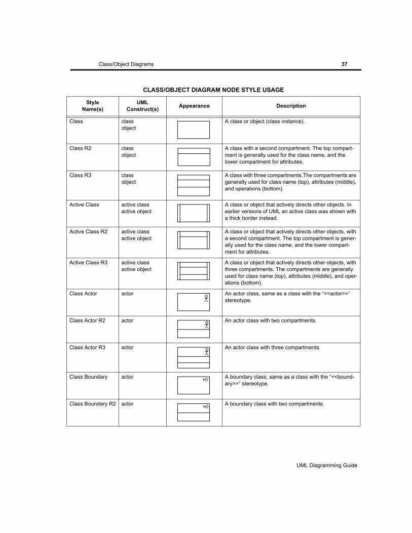
CLASS/OBJECT DIAGRAM NODE STYLE USAGE
StyleName(s)
UML Construct(s) Appearance Description
Class classobject
A class or object (class instance).
Class R2 classobject
A class with a second compartment. The top compart-ment is generally used for the class name, and the lower compartment for attributes.
Class R3 classobject
A class with three compartments.The compartments are generally used for class name (top), attributes (middle), and operations (bottom).
Active Class active classactive object
A class or object that actively directs other objects. In earlier versions of UML an active class was shown with a thick border instead.
Active Class R2 active classactive object
A class or object that actively directs other objects, with a second compartment. The top compartment is gener-ally used for the class name, and the lower compart-ment for attributes.
Active Class R3 active classactive object
A class or object that actively directs other objects, with three compartments. The compartments are generally used for class name (top), attributes (middle), and oper-ations (bottom).
Class Actor actor An actor class, same as a class with the “<<actor>>” stereotype.
Class Actor R2 actor An actor class with two compartments.
Class Actor R3 actor An actor class with three compartments.
Class Boundary actor A boundary class, same as a class with the “<<bound-ary>>” stereotype.
Class Boundary R2 actor A boundary class with two compartments.
UML Diagramming Guide
EDGE Diagrammer User’s Guide
Page 37 of 96
Last Modified May 18, 2009 5:39 pm
Filename: S:\UFLOW\UMLDOC\UML Diagramming Guide.fm
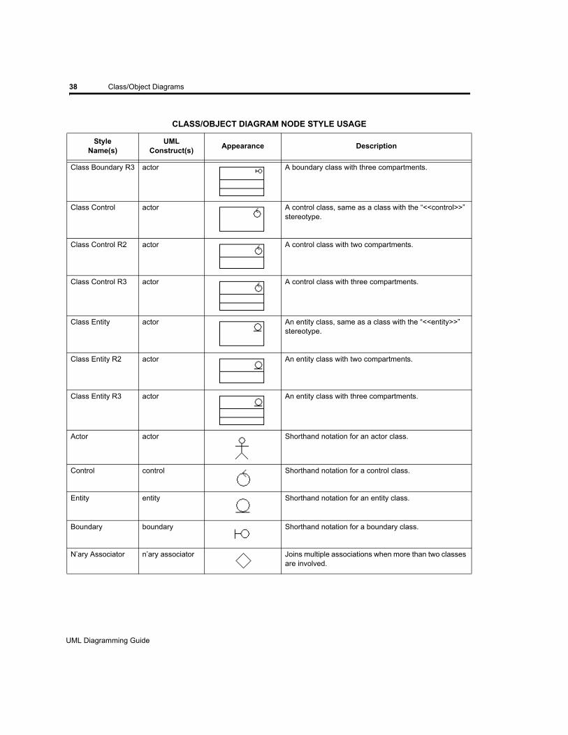
38 Class/Object Diagrams
Class Boundary R3 actor A boundary class with three compartments.
Class Control actor A control class, same as a class with the “<<control>>” stereotype.
Class Control R2 actor A control class with two compartments.
Class Control R3 actor A control class with three compartments.
Class Entity actor An entity class, same as a class with the “<<entity>>” stereotype.
Class Entity R2 actor An entity class with two compartments.
Class Entity R3 actor An entity class with three compartments.
Actor actor Shorthand notation for an actor class.
Control control Shorthand notation for a control class.
Entity entity Shorthand notation for an entity class.
Boundary boundary Shorthand notation for a boundary class.
N’ary Associator n’ary associator Joins multiple associations when more than two classes are involved.
CLASS/OBJECT DIAGRAM NODE STYLE USAGE
StyleName(s)
UML Construct(s) Appearance Description
UML Diagramming Guide
EDGE Diagrammer User’s Guide - Beta Version
Page 38 of 96
Last Modified May 18, 2009 5:39 pm
Filename: S:\UFLOW\UMLDOC\UML Diagramming Guide.fm
Class/Object Diagrams 39
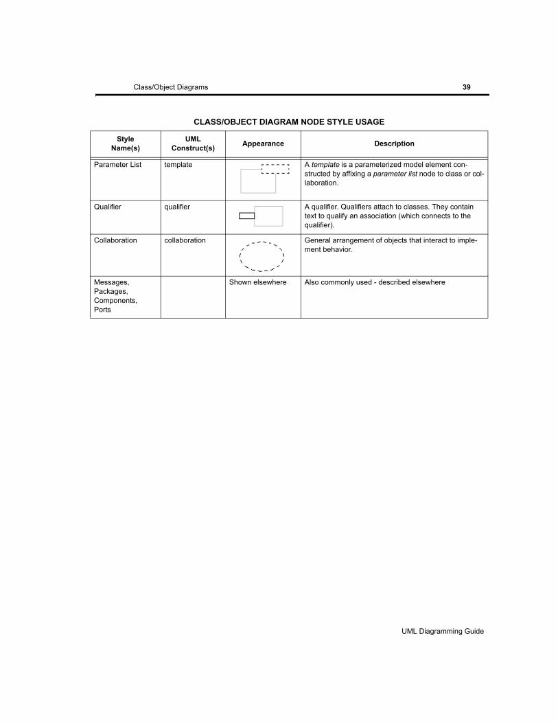
Parameter List template A template is a parameterized model element con-structed by affixing a parameter list node to class or col-laboration.
Qualifier qualifier A qualifier. Qualifiers attach to classes. They contain text to qualify an association (which connects to the qualifier).
Collaboration collaboration General arrangement of objects that interact to imple-ment behavior.
Messages,Packages,Components,Ports
Shown elsewhere Also commonly used - described elsewhere
CLASS/OBJECT DIAGRAM NODE STYLE USAGE
StyleName(s)
UML Construct(s) Appearance Description
UML Diagramming Guide
EDGE Diagrammer User’s Guide
Page 39 of 96
Last Modified May 18, 2009 5:39 pm
Filename: S:\UFLOW\UMLDOC\UML Diagramming Guide.fm

40 Class/Object Diagrams
AssociationsAssociations are the most common type of paths found in Class and Object diagrams. They show relationships between classes and objects such as generalization, aggregation, composition, navigability, and so on.
At its simplest, an association is a solid line connecting two classes or objects. However the association can be adorned by different types of terminators (arrowheads) and labels that represent attributes of the association like its name, direction, roles, multiplicities, and constraints.
We’ve provided styles that represent the most common types of associations “Association”, “Directional Association”, “Bidirectional Association”, “Generalization”, “Aggregation”, and “Composition”. However you can use any association style to define an association between classes and alter it by changing terminators or adding labels to arrive at any possible association.
Association Navigability
Navigability of associations is represented by simple stick arrows. Navigability is not always shown in a diagram. I this case no arrows are included. Although in diagrams where navigability is shown, an association with out arrows is synonymous with bidirectional navigability. Optionally a small X can be included as an association terminator to explicitly show that the association is unidirectional.
In addition to the normal “Association” path style, we include the two common variations “Directional Association” and “Bidirectional Association”. We don’t provide styles for all the possible permutations such as those that involve the less frequently used unidirectional terminator shown. To get a unidirectional indicator, create a directional indicator, then right click on the endpoint without a terminator and chose the terminator for the “X”.
UML Diagramming Guide
EDGE Diagrammer User’s Guide - Beta Version
Page 40 of 96
Last Modified May 18, 2009 5:39 pm
Filename: S:\UFLOW\UMLDOC\UML Diagramming Guide.fm

Class/Object Diagrams 41
Association End LabelsAssociations make liberal use of end labels to add information to the meaning of the association. Rolenames, constraints, ordering, visibility, interface specifiers, and changeability are all denoted
by end labels (as are multiplicities described in the following section.)
Pacestar UML Diagrammer supports end labels with a feature called Flow Labels in which a label can be created that attaches to both the node and one end of a path. In the case of the association shown here, the rolename “role” is attached as a flow label at the point where the association meets a class node. As a flow label, whenever the nodes and path move relative to one another, the label will move to a suitable location as close as possible to the endpoint of the path but not overlapping either the path or the node.
Creating a flow label is simple. Choose your label style. Then position the text caret cursor over the position where a flow label would appear. This will be confirmed by a small dotted rectangle with another dotted line leading to the path endpoint. If you click to create the label it will then be a flow label. Each of the four locations where the path meets the nodes can have a flow label (above and below on each end). See the main user guide or online help for more detailed instructions on using flow labels.
Association MultiplicitiesMultiplicities show how many of one class are associated with another, or how many are permitted to be. Multiplicities can be added to associations just like end labels described in the previous section.
However, because multiplicities are usually one of a very few varieties, we’ve added shortcut styles with predefined text so that you can add a multiplicity without even having to do any typing. The pre-defined common multiplicities are “*” (meaning any number, zero or more), “1” (obviously meaning just one), “0..1” (meaning one if any), or “1..*” (meaning at least 1). To add one of these multiplicities, simple click on the corresponding style bar button, and then click it into place, being sure to let it snap into a flow label slot as described for end labels in the previous section. You can of course, edit the text after creating the label if you require a different multiplicity expression.
UML Diagramming Guide
EDGE Diagrammer User’s Guide
Page 41 of 96
Last Modified May 18, 2009 5:39 pm
Filename: S:\UFLOW\UMLDOC\UML Diagramming Guide.fm
42 Class/Object Diagrams
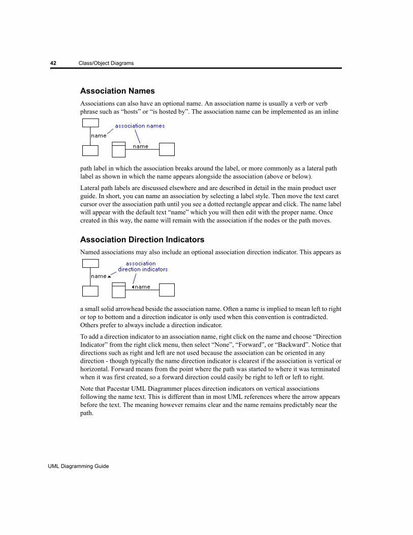
Association NamesAssociations can also have an optional name. An association name is usually a verb or verb phrase such as “hosts” or “is hosted by”. The association name can be implemented as an inline
path label in which the association breaks around the label, or more commonly as a lateral path label as shown in which the name appears alongside the association (above or below).
Lateral path labels are discussed elsewhere and are described in detail in the main product user guide. In short, you can name an association by selecting a label style. Then move the text caret cursor over the association path until you see a dotted rectangle appear and click. The name label will appear with the default text “name” which you will then edit with the proper name. Once created in this way, the name will remain with the association if the nodes or the path moves.
Association Direction IndicatorsNamed associations may also include an optional association direction indicator. This appears as
a small solid arrowhead beside the association name. Often a name is implied to mean left to right or top to bottom and a direction indicator is only used when this convention is contradicted. Others prefer to always include a direction indicator.
To add a direction indicator to an association name, right click on the name and choose “Direction Indicator” from the right click menu, then select “None”, “Forward”, or “Backward”. Notice that directions such as right and left are not used because the association can be oriented in any direction - though typically the name direction indicator is clearest if the association is vertical or horizontal. Forward means from the point where the path was started to where it was terminated when it was first created, so a forward direction could easily be right to left or left to right.
Note that Pacestar UML Diagrammer places direction indicators on vertical associations following the name text. This is different than in most UML references where the arrow appears before the text. The meaning however remains clear and the name remains predictably near the path.
UML Diagramming Guide
EDGE Diagrammer User’s Guide - Beta Version
Page 42 of 96
Last Modified May 18, 2009 5:39 pm
Filename: S:\UFLOW\UMLDOC\UML Diagramming Guide.fm
Class/Object Diagrams 43
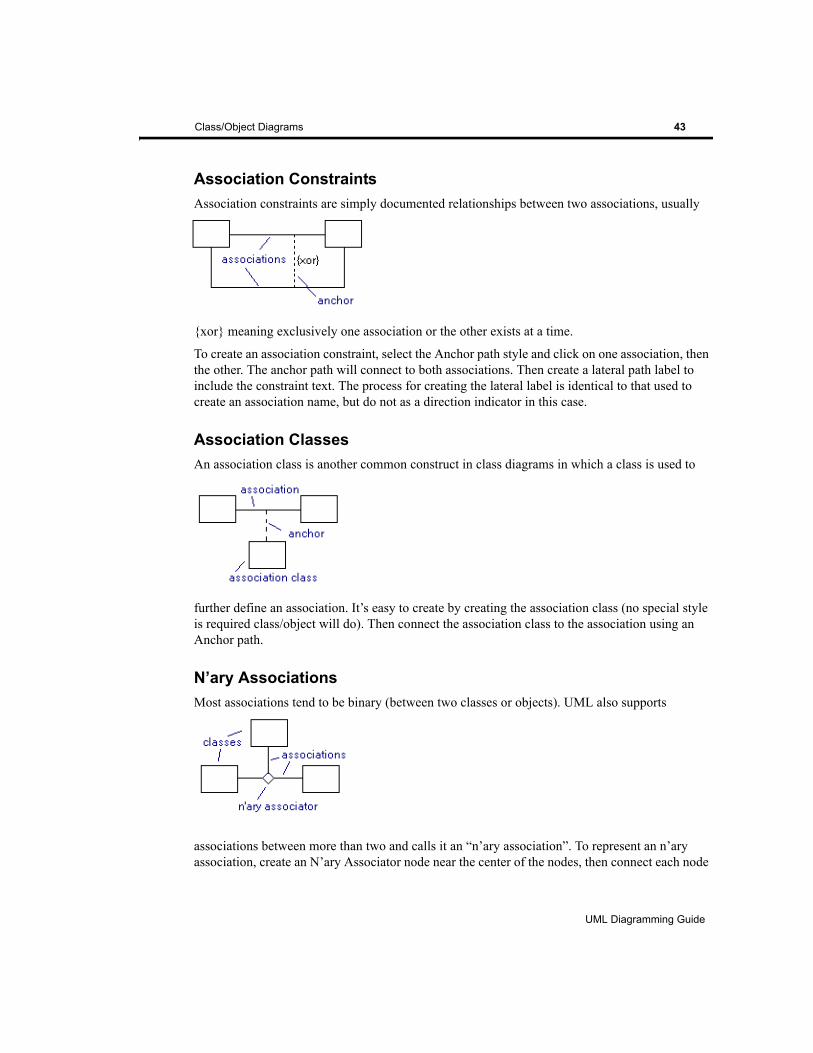
Association ConstraintsAssociation constraints are simply documented relationships between two associations, usually
{xor} meaning exclusively one association or the other exists at a time.
To create an association constraint, select the Anchor path style and click on one association, then the other. The anchor path will connect to both associations. Then create a lateral path label to include the constraint text. The process for creating the lateral label is identical to that used to create an association name, but do not as a direction indicator in this case.
Association ClassesAn association class is another common construct in class diagrams in which a class is used to
further define an association. It’s easy to create by creating the association class (no special style is required class/object will do). Then connect the association class to the association using an Anchor path.
N’ary AssociationsMost associations tend to be binary (between two classes or objects). UML also supports
associations between more than two and calls it an “n’ary association”. To represent an n’ary association, create an N’ary Associator node near the center of the nodes, then connect each node
UML Diagramming Guide
EDGE Diagrammer User’s Guide
Page 43 of 96
Last Modified May 18, 2009 5:39 pm
Filename: S:\UFLOW\UMLDOC\UML Diagramming Guide.fm
44 Class/Object Diagrams
to the N’ary Associator and add the appropriate end labels and multiplicities as needed. You can name any or all of the association links (and add direction indicators if you like), or you can add a node label to the n’ary associator instead to add a single name to the association if you prefer.
QualifiersQualifiers attach to class symbols to add information to association paths.
A qualifier can attach to any side of a class as show. And a single class can have any number of qualifiers.
An association that is attached to a qualifier can be annotated in all the usual ways. You can add an association name, direction indicator, multiplicities, rolenames, constraints and so on. Labels that generally attach to the ends of the association as flow symbols where the association meets the class, should instead can be placed where the association meets the qualifier.
Qualifiers are attachable nodes that attach to the edges of classes. Like all attachable nodes, you create the base node first (in this case the class), then create the attachable node (in this case the qualifier) and snap it into place on the base node where it attaches for the purposes or moving, copying, and so on (see Attachable Nodes on page 12).
Adding Qualifiers to ClassesQualifiers automatically cling to the edge of any class/object symbol.
To add a qualifier to a class1. Select the qualifier symbol from the style bar.2. Move the cursor near any edge of a class symbol until it snaps into place. It you prefer the
qualifier not to snap into place, hold the CTRL key.
UML Diagramming Guide
EDGE Diagrammer User’s Guide - Beta Version
Page 44 of 96
Last Modified May 18, 2009 5:39 pm
Filename: S:\UFLOW\UMLDOC\UML Diagramming Guide.fm
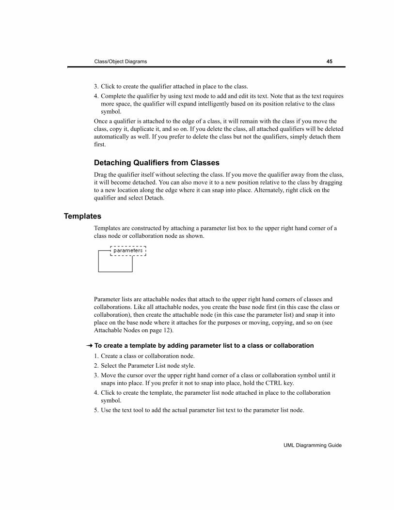
Class/Object Diagrams 45
3. Click to create the qualifier attached in place to the class.4. Complete the qualifier by using text mode to add and edit its text. Note that as the text requires
more space, the qualifier will expand intelligently based on its position relative to the class symbol.
Once a qualifier is attached to the edge of a class, it will remain with the class if you move the class, copy it, duplicate it, and so on. If you delete the class, all attached qualifiers will be deleted automatically as well. If you prefer to delete the class but not the qualifiers, simply detach them first.
Detaching Qualifiers from ClassesDrag the qualifier itself without selecting the class. If you move the qualifier away from the class, it will become detached. You can also move it to a new position relative to the class by dragging to a new location along the edge where it can snap into place. Alternately, right click on the qualifier and select Detach.
TemplatesTemplates are constructed by attaching a parameter list box to the upper right hand corner of a class node or collaboration node as shown.
Parameter lists are attachable nodes that attach to the upper right hand corners of classes and collaborations. Like all attachable nodes, you create the base node first (in this case the class or collaboration), then create the attachable node (in this case the parameter list) and snap it into place on the base node where it attaches for the purposes or moving, copying, and so on (see Attachable Nodes on page 12).
To create a template by adding parameter list to a class or collaboration1. Create a class or collaboration node.2. Select the Parameter List node style.3. Move the cursor over the upper right hand corner of a class or collaboration symbol until it
snaps into place. If you prefer it not to snap into place, hold the CTRL key.4. Click to create the template, the parameter list node attached in place to the collaboration
symbol.5. Use the text tool to add the actual parameter list text to the parameter list node.
UML Diagramming Guide
EDGE Diagrammer User’s Guide
Page 45 of 96
Last Modified May 18, 2009 5:39 pm
Filename: S:\UFLOW\UMLDOC\UML Diagramming Guide.fm
46 Class/Object Diagrams
Once a parameter list is attached to a class or collaboration, it will remain with it if you move the class or collaboration, copy it, duplicate it, and so on. If you delete the class or collaboration, the parameter list will be deleted automatically as well. If you prefer to delete the class or collaboration but not the parameter list, simply detach it first.
To detach a parameter list from a class or collaboration, right click on the parameter list and select Detach from the right click menu.
A parameter list cannot be repositioned while attached to a class or collaboration. To reposition it, detach it and re-attach it at a new location.
UML Diagramming Guide
EDGE Diagrammer User’s Guide - Beta Version
Page 46 of 96
Last Modified May 18, 2009 5:39 pm
Filename: S:\UFLOW\UMLDOC\UML Diagramming Guide.fm
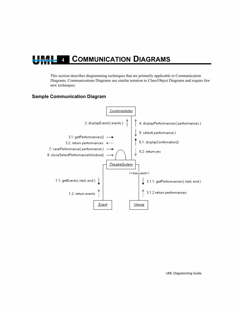
CHAPTER4 COMMUNICATION DIAGRAMS
This section describes diagramming techniques that are primarily applicable to Communication Diagrams. Communications Diagrams use similar notation to Class/Object Diagrams and require few new techniques.
Sample Communication Diagram
UML Diagramming Guide
EDGE Diagrammer User’s Guide
Page 47 of 96
Last Modified May 18, 2009 5:39 pm
Filename: S:\UFLOW\UMLDOC\UML Diagramming Guide.fm
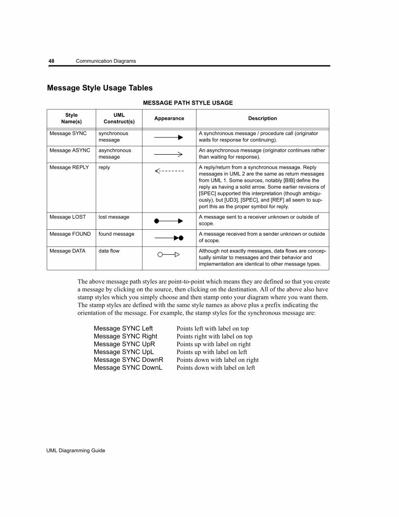
48 Communication Diagrams
Message Style Usage Tables
The above message path styles are point-to-point which means they are defined so that you create a message by clicking on the source, then clicking on the destination. All of the above also have stamp styles which you simply choose and then stamp onto your diagram where you want them. The stamp styles are defined with the same style names as above plus a prefix indicating the orientation of the message. For example, the stamp styles for the synchronous message are:
Message SYNC Left Points left with label on top Message SYNC Right Points right with label on top Message SYNC UpR Points up with label on right Message SYNC UpL Points up with label on left Message SYNC DownR Points down with label on right Message SYNC DownL Points down with label on left
MESSAGE PATH STYLE USAGE
StyleName(s)
UML Construct(s) Appearance Description
Message SYNC synchronous message
A synchronous message / procedure call (originator waits for response for continuing).
Message ASYNC asynchronous message
An asynchronous message (originator continues rather than waiting for response).
Message REPLY reply A reply/return from a synchronous message. Reply messages in UML 2 are the same as return messages from UML 1. Some sources, notably [BIB] define the reply as having a solid arrow. Some earlier revisions of [SPEC] supported this interpretation (though ambigu-ously), but [UD3], [SPEC], and [REF] all seem to sup-port this as the proper symbol for reply.
Message LOST lost message A message sent to a receiver unknown or outside of scope.
Message FOUND found message A message received from a sender unknown or outside of scope.
Message DATA data flow Although not exactly messages, data flows are concep-tually similar to messages and their behavior and implementation are identical to other message types.
UML Diagramming Guide
EDGE Diagrammer User’s Guide - Beta Version
Page 48 of 96
Last Modified May 18, 2009 5:39 pm
Filename: S:\UFLOW\UMLDOC\UML Diagramming Guide.fm
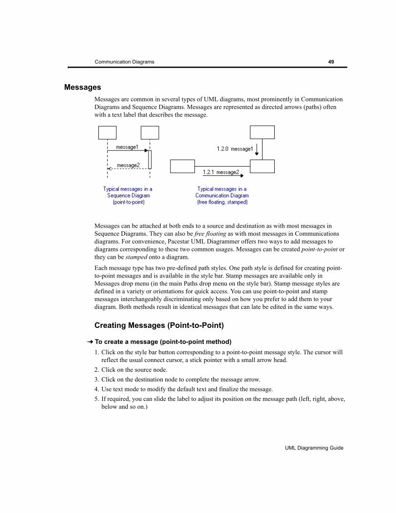
Communication Diagrams 49
MessagesMessages are common in several types of UML diagrams, most prominently in Communication Diagrams and Sequence Diagrams. Messages are represented as directed arrows (paths) often with a text label that describes the message.
Messages can be attached at both ends to a source and destination as with most messages in Sequence Diagrams. They can also be free floating as with most messages in Communications diagrams. For convenience, Pacestar UML Diagrammer offers two ways to add messages to diagrams corresponding to these two common usages. Messages can be created point-to-point or they can be stamped onto a diagram.
Each message type has two pre-defined path styles. One path style is defined for creating point-to-point messages and is available in the style bar. Stamp messages are available only in Messages drop menu (in the main Paths drop menu on the style bar). Stamp message styles are defined in a variety or orientations for quick access. You can use point-to-point and stamp messages interchangeably discriminating only based on how you prefer to add them to your diagram. Both methods result in identical messages that can late be edited in the same ways.
Creating Messages (Point-to-Point)
To create a message (point-to-point method)1. Click on the style bar button corresponding to a point-to-point message style. The cursor will
reflect the usual connect cursor, a stick pointer with a small arrow head.2. Click on the source node.3. Click on the destination node to complete the message arrow.4. Use text mode to modify the default text and finalize the message. 5. If required, you can slide the label to adjust its position on the message path (left, right, above,
below and so on.)
UML Diagramming Guide
EDGE Diagrammer User’s Guide
Page 49 of 96
Last Modified May 18, 2009 5:39 pm
Filename: S:\UFLOW\UMLDOC\UML Diagramming Guide.fm
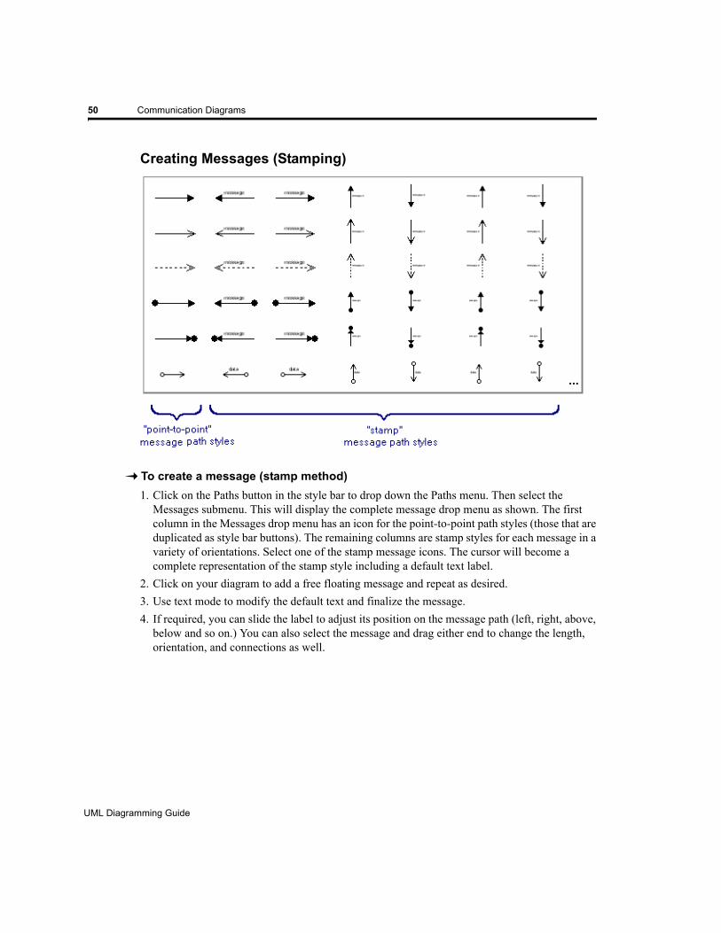
50 Communication Diagrams
Creating Messages (Stamping)
To create a message (stamp method)1. Click on the Paths button in the style bar to drop down the Paths menu. Then select the
Messages submenu. This will display the complete message drop menu as shown. The first column in the Messages drop menu has an icon for the point-to-point path styles (those that are duplicated as style bar buttons). The remaining columns are stamp styles for each message in a variety of orientations. Select one of the stamp message icons. The cursor will become a complete representation of the stamp style including a default text label.
2. Click on your diagram to add a free floating message and repeat as desired.3. Use text mode to modify the default text and finalize the message.4. If required, you can slide the label to adjust its position on the message path (left, right, above,
below and so on.) You can also select the message and drag either end to change the length, orientation, and connections as well.
UML Diagramming Guide
EDGE Diagrammer User’s Guide - Beta Version
Page 50 of 96
Last Modified May 18, 2009 5:39 pm
Filename: S:\UFLOW\UMLDOC\UML Diagramming Guide.fm
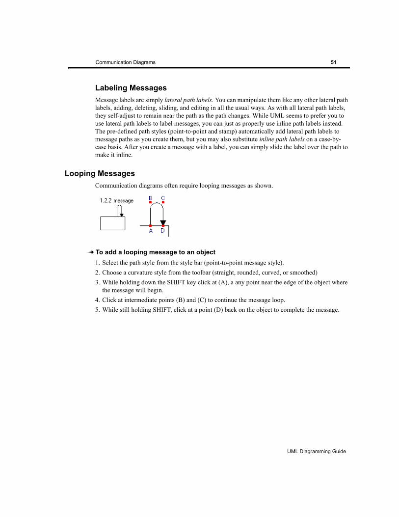
Communication Diagrams 51
Labeling MessagesMessage labels are simply lateral path labels. You can manipulate them like any other lateral path labels, adding, deleting, sliding, and editing in all the usual ways. As with all lateral path labels, they self-adjust to remain near the path as the path changes. While UML seems to prefer you to use lateral path labels to label messages, you can just as properly use inline path labels instead. The pre-defined path styles (point-to-point and stamp) automatically add lateral path labels to message paths as you create them, but you may also substitute inline path labels on a case-by-case basis. After you create a message with a label, you can simply slide the label over the path to make it inline.
Looping MessagesCommunication diagrams often require looping messages as shown.
To add a looping message to an object1. Select the path style from the style bar (point-to-point message style).2. Choose a curvature style from the toolbar (straight, rounded, curved, or smoothed)3. While holding down the SHIFT key click at (A), a any point near the edge of the object where
the message will begin.4. Click at intermediate points (B) and (C) to continue the message loop.5. While still holding SHIFT, click at a point (D) back on the object to complete the message.
UML Diagramming Guide
EDGE Diagrammer User’s Guide
Page 51 of 96
Last Modified May 18, 2009 5:39 pm
Filename: S:\UFLOW\UMLDOC\UML Diagramming Guide.fm

52 Communication Diagrams
UML Diagramming Guide
EDGE Diagrammer User’s Guide - Beta Version
Page 52 of 96
Last Modified May 18, 2009 5:39 pm
Filename: S:\UFLOW\UMLDOC\UML Diagramming Guide.fm
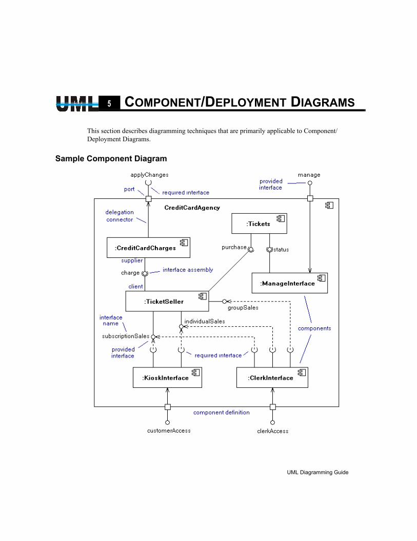
CHAPTER5 COMPONENT/DEPLOYMENT DIAGRAMS
This section describes diagramming techniques that are primarily applicable to Component/Deployment Diagrams.
Sample Component Diagram
UML Diagramming Guide
EDGE Diagrammer User’s Guide
Page 53 of 96
Last Modified May 18, 2009 5:39 pm
Filename: S:\UFLOW\UMLDOC\UML Diagramming Guide.fm
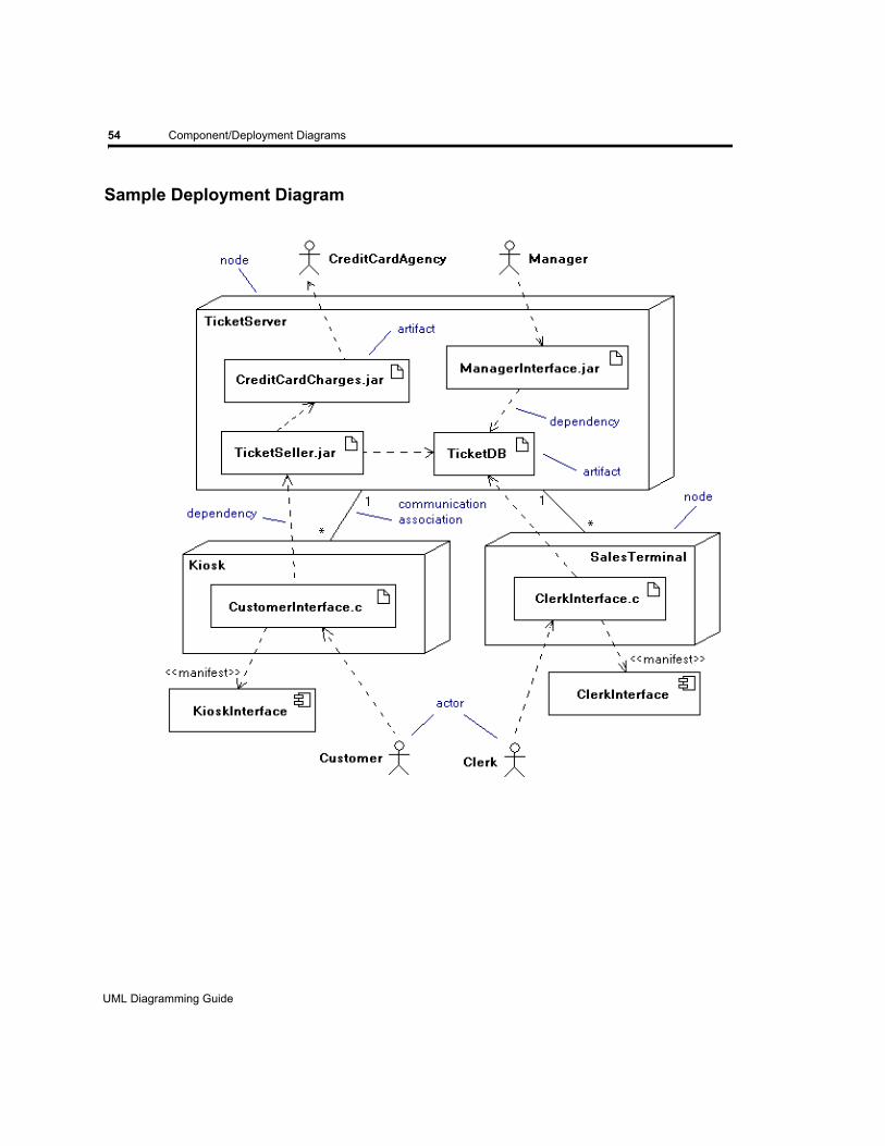
54 Component/Deployment Diagrams
Sample Deployment Diagram
UML Diagramming Guide
EDGE Diagrammer User’s Guide - Beta Version
Page 54 of 96
Last Modified May 18, 2009 5:39 pm
Filename: S:\UFLOW\UMLDOC\UML Diagramming Guide.fm
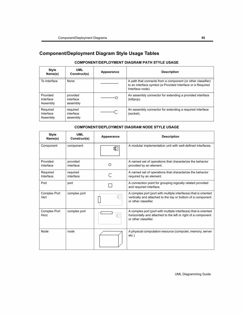
Component/Deployment Diagrams 55
Component/Deployment Diagram Style Usage Tables
COMPONENT/DEPLOYMENT DIAGRAM PATH STYLE USAGE
StyleName(s)
UML Construct(s) Appearance Description
To Interface None A path that connects from a component (or other classifier) to an interface symbol (a Provided Interface or a Required Interface node).
Provided InterfaceAssembly
providedinterfaceassembly
An assembly connector for extending a provided interface (lollipop).
RequiredInterfaceAssembly
requiredinterfaceassembly
An assembly connector for extending a required interface (socket).
COMPONENT/DEPLOYMENT DIAGRAM NODE STYLE USAGE
StyleName(s)
UML Construct(s) Appearance Description
Component component A modular implementation unit with well-defined interfaces.
Provided Interface
providedinterface
A named set of operations that characterize the behavior provided by an element.
Required Interface
requiredinterface
A named set of operations that characterize the behavior required by an element.
Port port A connection point for grouping logically related provided and required interface.
Complex Port Vert
complex port A complex port (port with multiple interfaces) that is oriented vertically and attached to the top or bottom of a component or other classifier.
Complex Port Horz
complex port A complex port (port with multiple interfaces) that is oriented horizontally and attached to the left or right of a component or other classifier.
Node node A physical computation resource (computer, memory, server etc.)
UML Diagramming Guide
EDGE Diagrammer User’s Guide
Page 55 of 96
Last Modified May 18, 2009 5:39 pm
Filename: S:\UFLOW\UMLDOC\UML Diagramming Guide.fm
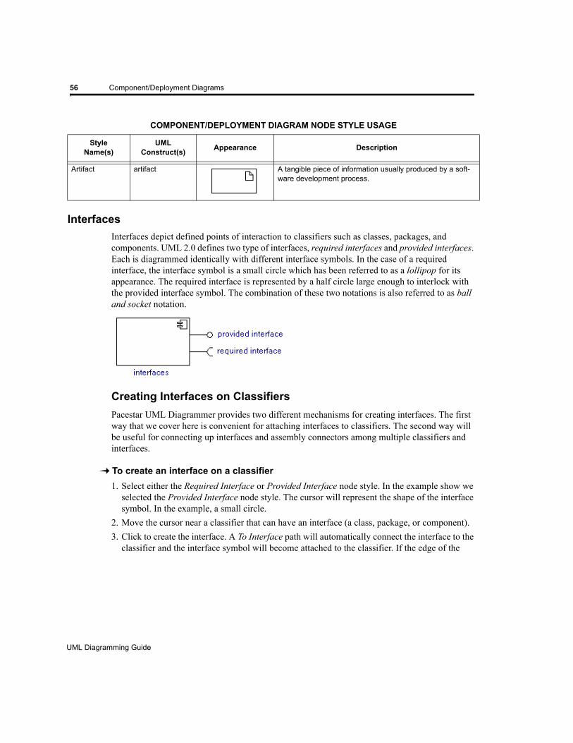
56 Component/Deployment Diagrams
InterfacesInterfaces depict defined points of interaction to classifiers such as classes, packages, and components. UML 2.0 defines two type of interfaces, required interfaces and provided interfaces. Each is diagrammed identically with different interface symbols. In the case of a required interface, the interface symbol is a small circle which has been referred to as a lollipop for its appearance. The required interface is represented by a half circle large enough to interlock with the provided interface symbol. The combination of these two notations is also referred to as ball and socket notation.
Creating Interfaces on ClassifiersPacestar UML Diagrammer provides two different mechanisms for creating interfaces. The first way that we cover here is convenient for attaching interfaces to classifiers. The second way will be useful for connecting up interfaces and assembly connectors among multiple classifiers and interfaces.
To create an interface on a classifier1. Select either the Required Interface or Provided Interface node style. In the example show we
selected the Provided Interface node style. The cursor will represent the shape of the interface symbol. In the example, a small circle.
2. Move the cursor near a classifier that can have an interface (a class, package, or component). 3. Click to create the interface. A To Interface path will automatically connect the interface to the
classifier and the interface symbol will become attached to the classifier. If the edge of the
Artifact artifact A tangible piece of information usually produced by a soft-ware development process.
COMPONENT/DEPLOYMENT DIAGRAM NODE STYLE USAGE
StyleName(s)
UML Construct(s) Appearance Description
UML Diagramming Guide
EDGE Diagrammer User’s Guide - Beta Version
Page 56 of 96
Last Modified May 18, 2009 5:39 pm
Filename: S:\UFLOW\UMLDOC\UML Diagramming Guide.fm
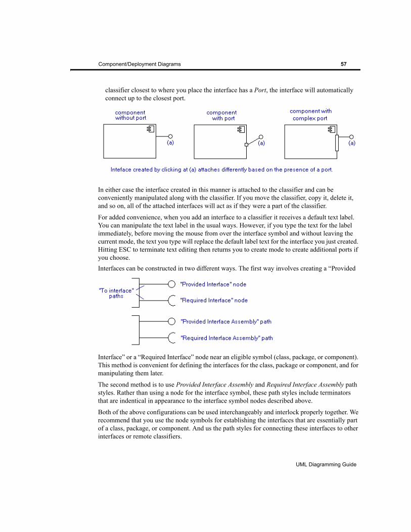
Component/Deployment Diagrams 57
classifier closest to where you place the interface has a Port, the interface will automatically connect up to the closest port.
In either case the interface created in this manner is attached to the classifier and can be conveniently manipulated along with the classifier. If you move the classifier, copy it, delete it, and so on, all of the attached interfaces will act as if they were a part of the classifier.
For added convenience, when you add an interface to a classifier it receives a default text label. You can manipulate the text label in the usual ways. However, if you type the text for the label immediately, before moving the mouse from over the interface symbol and without leaving the current mode, the text you type will replace the default label text for the interface you just created. Hitting ESC to terminate text editing then returns you to create mode to create additional ports if you choose.Interfaces can be constructed in two different ways. The first way involves creating a “Provided
Interface” or a “Required Interface” node near an eligible symbol (class, package, or component). This method is convenient for defining the interfaces for the class, package or component, and for manipulating them later.
The second method is to use Provided Interface Assembly and Required Interface Assembly path styles. Rather than using a node for the interface symbol, these path styles include terminators that are indentical in appearance to the interface symbol nodes described above.
Both of the above configurations can be used interchangeably and interlock properly together. We recommend that you use the node symbols for establishing the interfaces that are essentially part of a class, package, or component. And us the path styles for connecting these interfaces to other interfaces or remote classifiers.
UML Diagramming Guide
EDGE Diagrammer User’s Guide
Page 57 of 96
Last Modified May 18, 2009 5:39 pm
Filename: S:\UFLOW\UMLDOC\UML Diagramming Guide.fm

58 Component/Deployment Diagrams
To connect a path to an interface belonging to a classifier1. Select either the Required Interface Assembly path style or the Provided Interface Assembly
path styles.2. Click on the originating symbol.3. Click on intermediate points as necessary to establish the route of the path.4. Click on the interface belonging to a classifier to terminate the path. Normally you will use a
Provided Interface Assembly path style to connect to a Required Interface node and vice versa.
Labeling Interfaces
Interfaces defined on classifiers often have a name. Add a name using the node label. Simply right click on the interface symbol and select Add Node Symbol and choose a label position. You can then use text mode to change the label text and use select mode to drag the position of the label relative to the interface symbol.
Moving InterfacesWhen you establish interfaces on a classifier using interface nodes (the recommended method described in the previous section), you can adjust the interface symbol by simply dragging them. The connection to the classifier will automatically adjust to the new position.
Assembly Connectors
Often you will see a complete interface assembly connector like the one show drawn on a diagram but neither side (the ball or socket) is in the immediate vicinity of a classifier (class, package, or component). In this case, both ‘sides’ of the assembly connector can be created by Interface Assembly path styles that meet at a common point.
To create an interface assembly (neither side part of a classifier)1. Select either the Required Interface Assembly or the Provided Interface Assembly path style (as
shown in the example) by clicking on its button in the style bar.2. Click on the source (usually a classifier), then click on any intermediate points needed to
define the route. In the example, click on (a) then (b).
UML Diagramming Guide
EDGE Diagrammer User’s Guide - Beta Version
Page 58 of 96
Last Modified May 18, 2009 5:39 pm
Filename: S:\UFLOW\UMLDOC\UML Diagramming Guide.fm
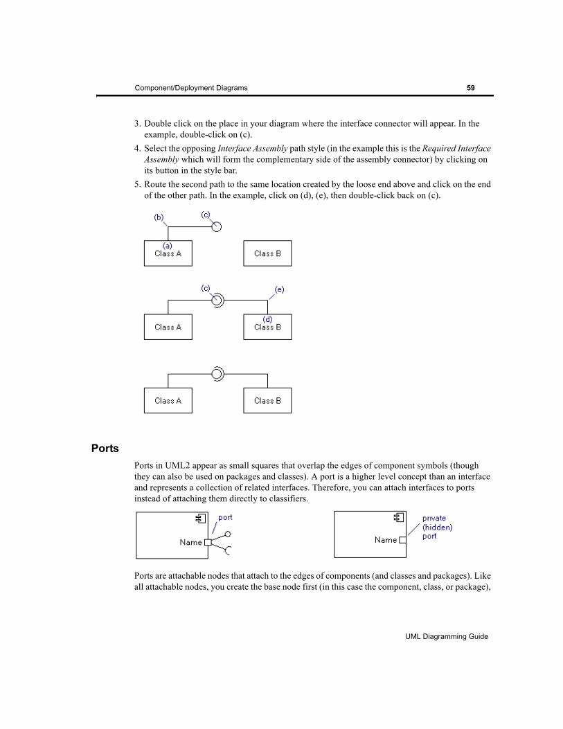
Component/Deployment Diagrams 59
3. Double click on the place in your diagram where the interface connector will appear. In the example, double-click on (c).
4. Select the opposing Interface Assembly path style (in the example this is the Required Interface Assembly which will form the complementary side of the assembly connector) by clicking on its button in the style bar.
5. Route the second path to the same location created by the loose end above and click on the end of the other path. In the example, click on (d), (e), then double-click back on (c).
PortsPorts in UML2 appear as small squares that overlap the edges of component symbols (though they can also be used on packages and classes). A port is a higher level concept than an interface and represents a collection of related interfaces. Therefore, you can attach interfaces to ports instead of attaching them directly to classifiers.
Ports are attachable nodes that attach to the edges of components (and classes and packages). Like all attachable nodes, you create the base node first (in this case the component, class, or package),
UML Diagramming Guide
EDGE Diagrammer User’s Guide
Page 59 of 96
Last Modified May 18, 2009 5:39 pm
Filename: S:\UFLOW\UMLDOC\UML Diagramming Guide.fm
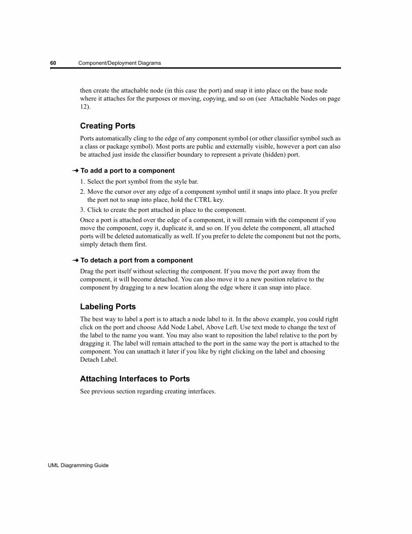
60 Component/Deployment Diagrams
then create the attachable node (in this case the port) and snap it into place on the base node where it attaches for the purposes or moving, copying, and so on (see Attachable Nodes on page 12).
Creating PortsPorts automatically cling to the edge of any component symbol (or other classifier symbol such as a class or package symbol). Most ports are public and externally visible, however a port can also be attached just inside the classifier boundary to represent a private (hidden) port.
To add a port to a component1. Select the port symbol from the style bar. 2. Move the cursor over any edge of a component symbol until it snaps into place. It you prefer
the port not to snap into place, hold the CTRL key.3. Click to create the port attached in place to the component.Once a port is attached over the edge of a component, it will remain with the component if you move the component, copy it, duplicate it, and so on. If you delete the component, all attached ports will be deleted automatically as well. If you prefer to delete the component but not the ports, simply detach them first.
To detach a port from a componentDrag the port itself without selecting the component. If you move the port away from the component, it will become detached. You can also move it to a new position relative to the component by dragging to a new location along the edge where it can snap into place.
Labeling PortsThe best way to label a port is to attach a node label to it. In the above example, you could right click on the port and choose Add Node Label, Above Left. Use text mode to change the text of the label to the name you want. You may also want to reposition the label relative to the port by dragging it. The label will remain attached to the port in the same way the port is attached to the component. You can unattach it later if you like by right clicking on the label and choosing Detach Label.
Attaching Interfaces to PortsSee previous section regarding creating interfaces.
UML Diagramming Guide
EDGE Diagrammer User’s Guide - Beta Version
Page 60 of 96
Last Modified May 18, 2009 5:39 pm
Filename: S:\UFLOW\UMLDOC\UML Diagramming Guide.fm

Component/Deployment Diagrams 61
Repositioning PortsYou can drag a port to reposition it on the component or detach it. Dragging to reposition the port works similar to creating the port. You can choose to move it free of the component or attach to a different component or a different position on the same component.
UML Diagramming Guide
EDGE Diagrammer User’s Guide
Page 61 of 96
Last Modified May 18, 2009 5:39 pm
Filename: S:\UFLOW\UMLDOC\UML Diagramming Guide.fm

62 Component/Deployment Diagrams
UML Diagramming Guide
EDGE Diagrammer User’s Guide - Beta Version
Page 62 of 96
Last Modified May 18, 2009 5:39 pm
Filename: S:\UFLOW\UMLDOC\UML Diagramming Guide.fm
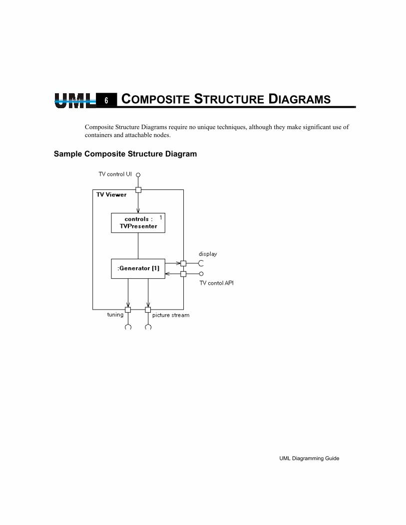
CHAPTER6 COMPOSITE STRUCTURE DIAGRAMS
Composite Structure Diagrams require no unique techniques, although they make significant use of containers and attachable nodes.
Sample Composite Structure Diagram
UML Diagramming Guide
EDGE Diagrammer User’s Guide
Page 63 of 96
Last Modified May 18, 2009 5:39 pm
Filename: S:\UFLOW\UMLDOC\UML Diagramming Guide.fm

64 Composite Structure Diagrams
UML Diagramming Guide
EDGE Diagrammer User’s Guide - Beta Version
Page 64 of 96
Last Modified May 18, 2009 5:39 pm
Filename: S:\UFLOW\UMLDOC\UML Diagramming Guide.fm
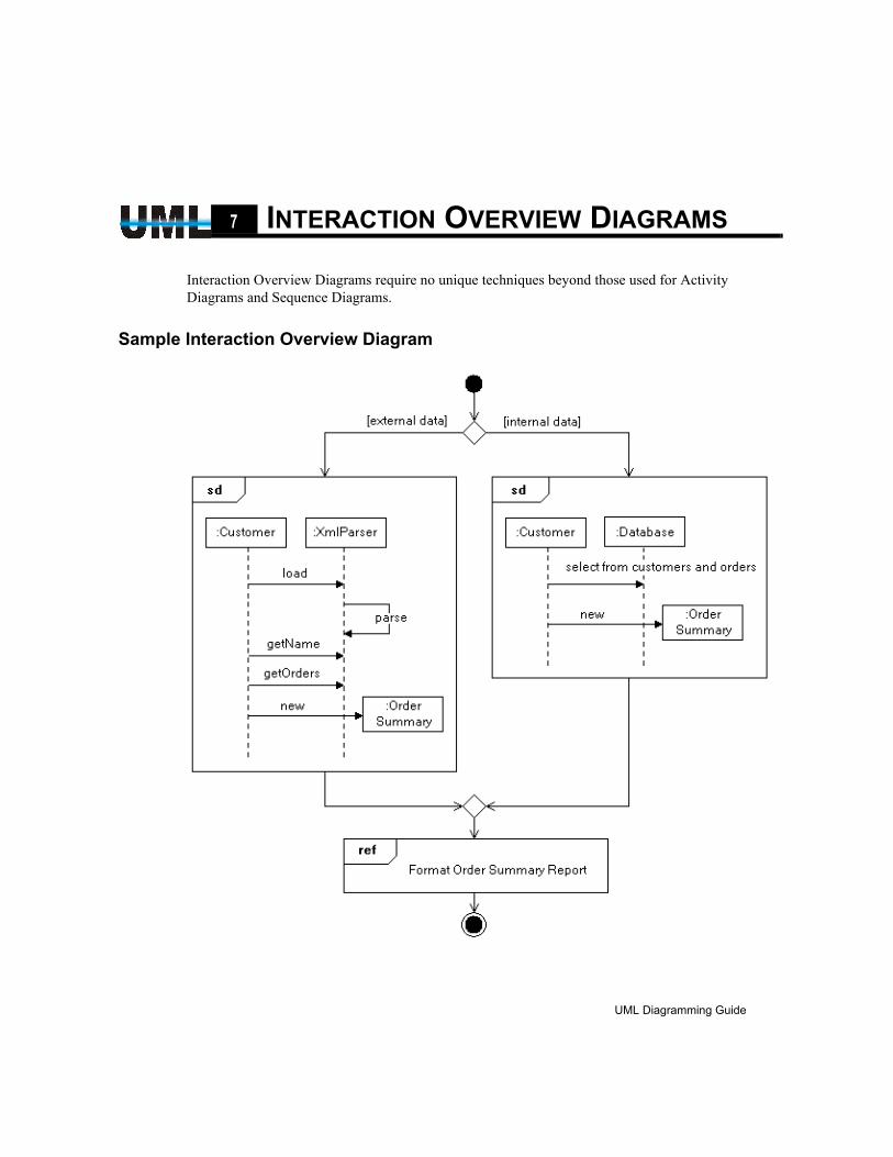
CHAPTER7 INTERACTION OVERVIEW DIAGRAMS
Interaction Overview Diagrams require no unique techniques beyond those used for Activity Diagrams and Sequence Diagrams.
Sample Interaction Overview Diagram
UML Diagramming Guide
EDGE Diagrammer User’s Guide
Page 65 of 96
Last Modified May 18, 2009 5:39 pm
Filename: S:\UFLOW\UMLDOC\UML Diagramming Guide.fm

66 Interaction Overview Diagrams
UML Diagramming Guide
EDGE Diagrammer User’s Guide - Beta Version
Page 66 of 96
Last Modified May 18, 2009 5:39 pm
Filename: S:\UFLOW\UMLDOC\UML Diagramming Guide.fm
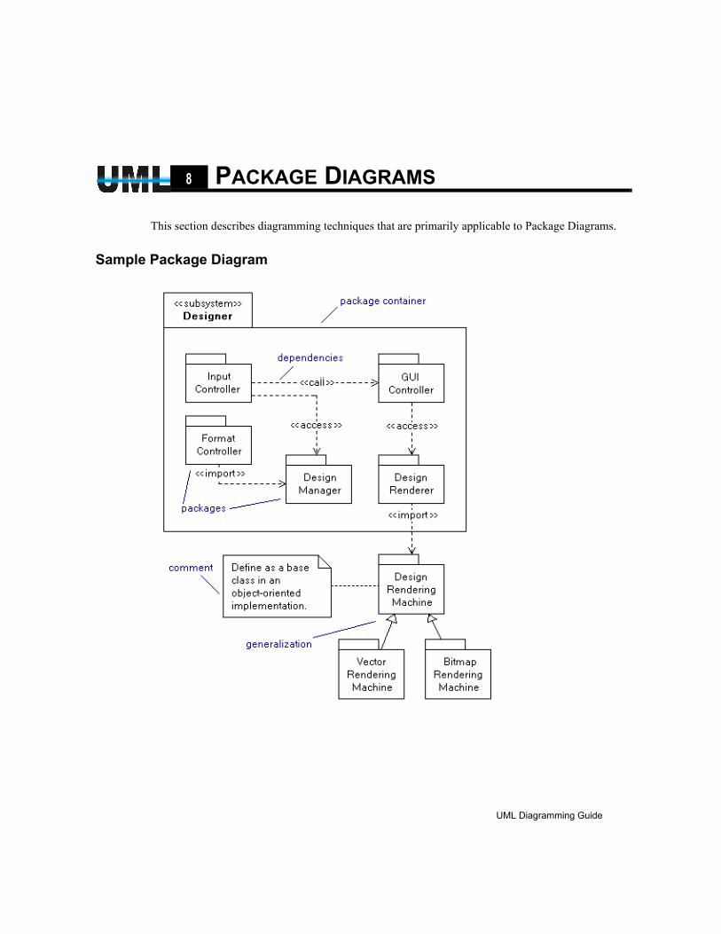
CHAPTER8 PACKAGE DIAGRAMS
This section describes diagramming techniques that are primarily applicable to Package Diagrams.
Sample Package Diagram
UML Diagramming Guide
EDGE Diagrammer User’s Guide
Page 67 of 96
Last Modified May 18, 2009 5:39 pm
Filename: S:\UFLOW\UMLDOC\UML Diagramming Guide.fm
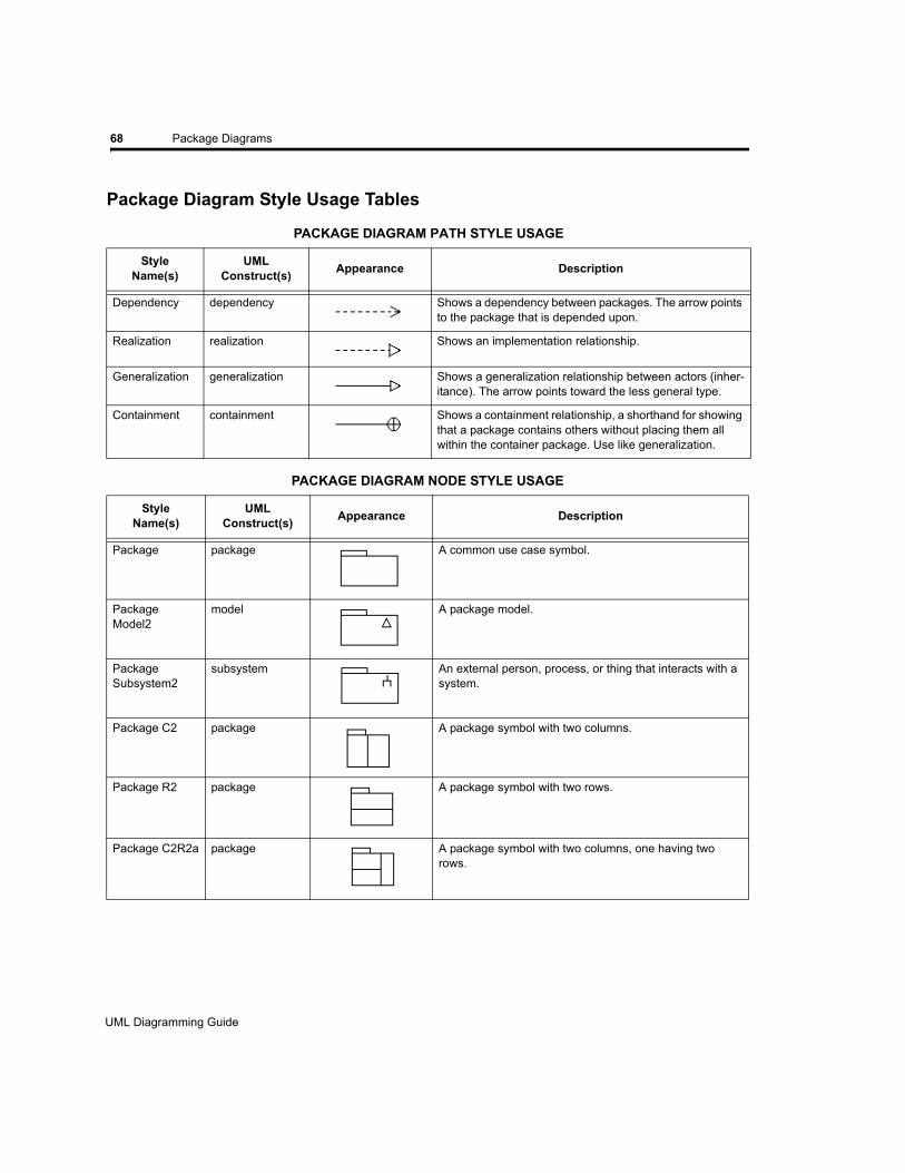
68 Package Diagrams
Package Diagram Style Usage Tables
PACKAGE DIAGRAM PATH STYLE USAGE
StyleName(s)
UML Construct(s) Appearance Description
Dependency dependency Shows a dependency between packages. The arrow points to the package that is depended upon.
Realization realization Shows an implementation relationship.
Generalization generalization Shows a generalization relationship between actors (inher-itance). The arrow points toward the less general type.
Containment containment Shows a containment relationship, a shorthand for showing that a package contains others without placing them all within the container package. Use like generalization.
PACKAGE DIAGRAM NODE STYLE USAGE
StyleName(s)
UML Construct(s) Appearance Description
Package package A common use case symbol.
Package Model2
model A package model.
Package Subsystem2
subsystem An external person, process, or thing that interacts with a system.
Package C2 package A package symbol with two columns.
Package R2 package A package symbol with two rows.
Package C2R2a package A package symbol with two columns, one having two rows.
UML Diagramming Guide
EDGE Diagrammer User’s Guide - Beta Version
Page 68 of 96
Last Modified May 18, 2009 5:39 pm
Filename: S:\UFLOW\UMLDOC\UML Diagramming Guide.fm
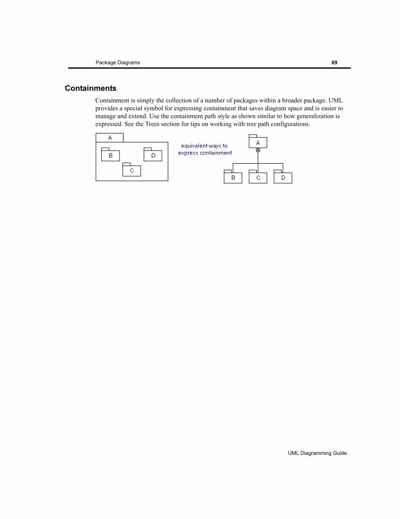
Package Diagrams 69
ContainmentsContainment is simply the collection of a number of packages within a broader package. UML provides a special symbol for expressing containment that saves diagram space and is easier to manage and extend. Use the containment path style as shown similar to how generalization is expressed. See the Trees section for tips on working with tree path configurations.
UML Diagramming Guide
EDGE Diagrammer User’s Guide
Page 69 of 96
Last Modified May 18, 2009 5:39 pm
Filename: S:\UFLOW\UMLDOC\UML Diagramming Guide.fm

70 Package Diagrams
UML Diagramming Guide
EDGE Diagrammer User’s Guide - Beta Version
Page 70 of 96
Last Modified May 18, 2009 5:39 pm
Filename: S:\UFLOW\UMLDOC\UML Diagramming Guide.fm
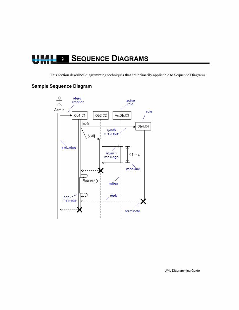
CHAPTER9 SEQUENCE DIAGRAMS
This section describes diagramming techniques that are primarily applicable to Sequence Diagrams.
Sample Sequence Diagram
UML Diagramming Guide
EDGE Diagrammer User’s Guide
Page 71 of 96
Last Modified May 18, 2009 5:39 pm
Filename: S:\UFLOW\UMLDOC\UML Diagramming Guide.fm
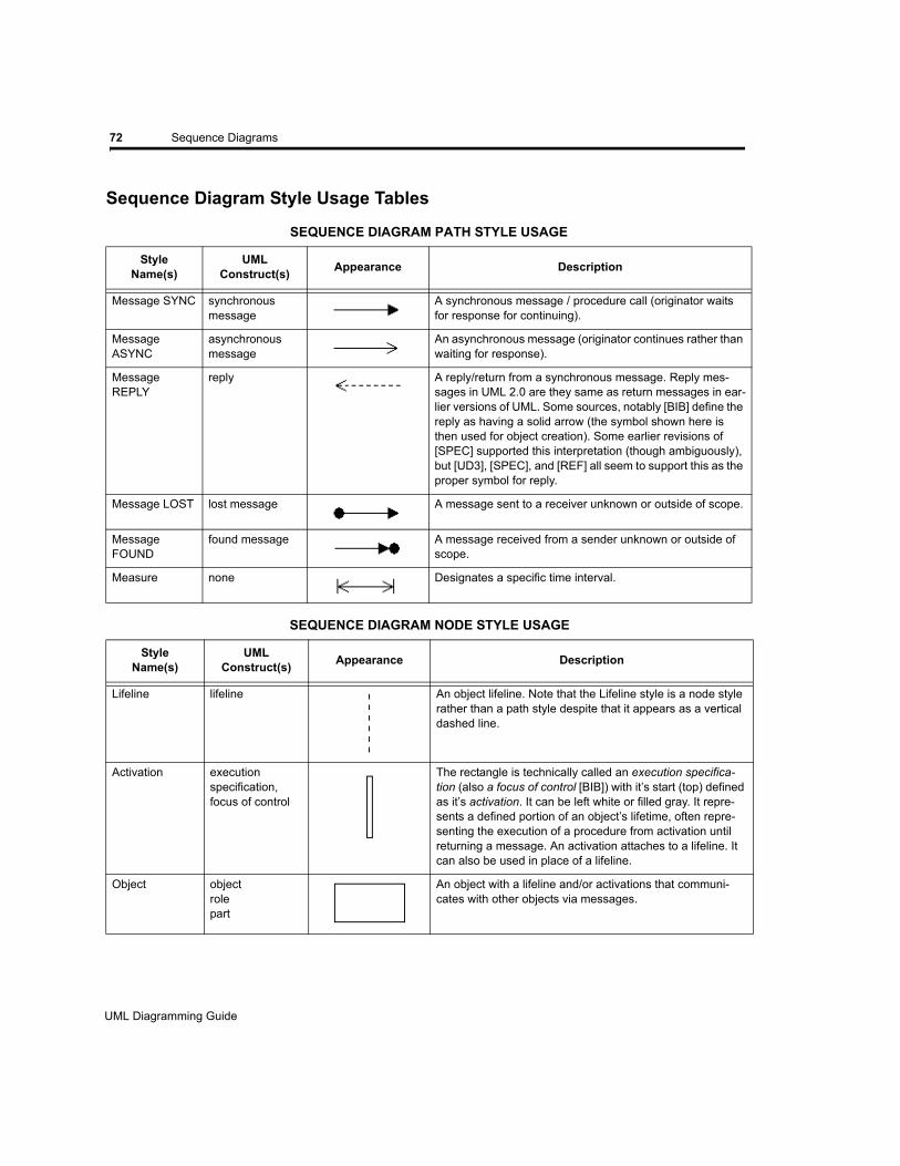
72 Sequence Diagrams
Sequence Diagram Style Usage Tables
SEQUENCE DIAGRAM PATH STYLE USAGE
StyleName(s)
UML Construct(s) Appearance Description
Message SYNC synchronous message
A synchronous message / procedure call (originator waits for response for continuing).
Message ASYNC
asynchronous message
An asynchronous message (originator continues rather than waiting for response).
Message REPLY
reply A reply/return from a synchronous message. Reply mes-sages in UML 2.0 are they same as return messages in ear-lier versions of UML. Some sources, notably [BIB] define the reply as having a solid arrow (the symbol shown here is then used for object creation). Some earlier revisions of [SPEC] supported this interpretation (though ambiguously), but [UD3], [SPEC], and [REF] all seem to support this as the proper symbol for reply.
Message LOST lost message A message sent to a receiver unknown or outside of scope.
Message FOUND
found message A message received from a sender unknown or outside of scope.
Measure none Designates a specific time interval.
SEQUENCE DIAGRAM NODE STYLE USAGE
StyleName(s)
UML Construct(s) Appearance Description
Lifeline lifeline An object lifeline. Note that the Lifeline style is a node style rather than a path style despite that it appears as a vertical dashed line.
Activation executionspecification,focus of control
The rectangle is technically called an execution specifica-tion (also a focus of control [BIB]) with it’s start (top) defined as it’s activation. It can be left white or filled gray. It repre-sents a defined portion of an object’s lifetime, often repre-senting the execution of a procedure from activation until returning a message. An activation attaches to a lifeline. It can also be used in place of a lifeline.
Object objectrole part
An object with a lifeline and/or activations that communi-cates with other objects via messages.
UML Diagramming Guide
EDGE Diagrammer User’s Guide - Beta Version
Page 72 of 96
Last Modified May 18, 2009 5:39 pm
Filename: S:\UFLOW\UMLDOC\UML Diagramming Guide.fm
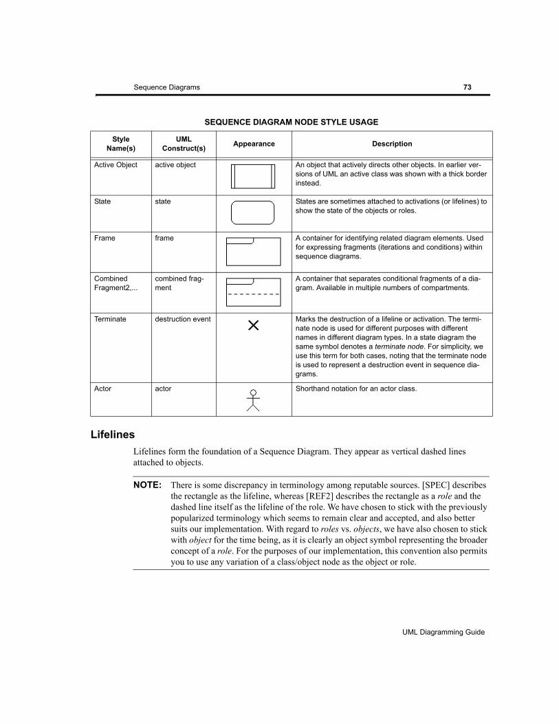
Sequence Diagrams 73
LifelinesLifelines form the foundation of a Sequence Diagram. They appear as vertical dashed lines attached to objects.
NOTE: There is some discrepancy in terminology among reputable sources. [SPEC] describes the rectangle as the lifeline, whereas [REF2] describes the rectangle as a role and the dashed line itself as the lifeline of the role. We have chosen to stick with the previously popularized terminology which seems to remain clear and accepted, and also better suits our implementation. With regard to roles vs. objects, we have also chosen to stick with object for the time being, as it is clearly an object symbol representing the broader concept of a role. For the purposes of our implementation, this convention also permits you to use any variation of a class/object node as the object or role.
Active Object active object An object that actively directs other objects. In earlier ver-sions of UML an active class was shown with a thick border instead.
State state States are sometimes attached to activations (or lifelines) to show the state of the objects or roles.
Frame frame A container for identifying related diagram elements. Used for expressing fragments (iterations and conditions) within sequence diagrams.
Combined Fragment2,...
combined frag-ment
A container that separates conditional fragments of a dia-gram. Available in multiple numbers of compartments.
Terminate destruction event Marks the destruction of a lifeline or activation. The termi-nate node is used for different purposes with different names in different diagram types. In a state diagram the same symbol denotes a terminate node. For simplicity, we use this term for both cases, noting that the terminate node is used to represent a destruction event in sequence dia-grams.
Actor actor Shorthand notation for an actor class.
SEQUENCE DIAGRAM NODE STYLE USAGE
StyleName(s)
UML Construct(s) Appearance Description
UML Diagramming Guide
EDGE Diagrammer User’s Guide
Page 73 of 96
Last Modified May 18, 2009 5:39 pm
Filename: S:\UFLOW\UMLDOC\UML Diagramming Guide.fm
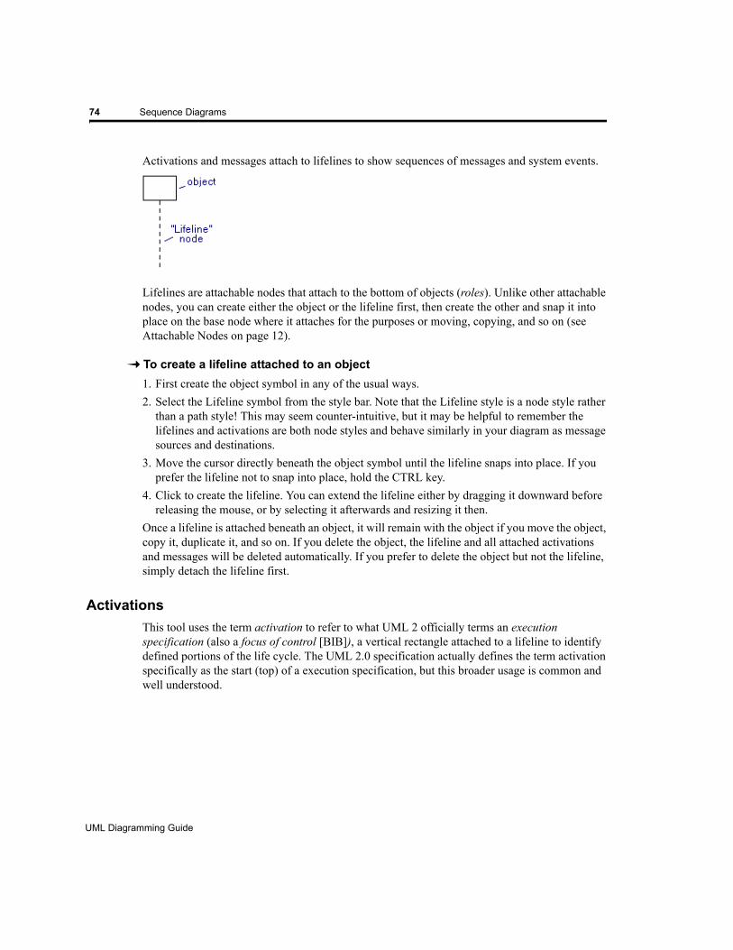
74 Sequence Diagrams
Activations and messages attach to lifelines to show sequences of messages and system events.
Lifelines are attachable nodes that attach to the bottom of objects (roles). Unlike other attachable nodes, you can create either the object or the lifeline first, then create the other and snap it into place on the base node where it attaches for the purposes or moving, copying, and so on (see Attachable Nodes on page 12).
To create a lifeline attached to an object1. First create the object symbol in any of the usual ways.2. Select the Lifeline symbol from the style bar. Note that the Lifeline style is a node style rather
than a path style! This may seem counter-intuitive, but it may be helpful to remember the lifelines and activations are both node styles and behave similarly in your diagram as message sources and destinations.
3. Move the cursor directly beneath the object symbol until the lifeline snaps into place. If you prefer the lifeline not to snap into place, hold the CTRL key.
4. Click to create the lifeline. You can extend the lifeline either by dragging it downward before releasing the mouse, or by selecting it afterwards and resizing it then.
Once a lifeline is attached beneath an object, it will remain with the object if you move the object, copy it, duplicate it, and so on. If you delete the object, the lifeline and all attached activations and messages will be deleted automatically. If you prefer to delete the object but not the lifeline, simply detach the lifeline first.
ActivationsThis tool uses the term activation to refer to what UML 2 officially terms an execution specification (also a focus of control [BIB]), a vertical rectangle attached to a lifeline to identify defined portions of the life cycle. The UML 2.0 specification actually defines the term activation specifically as the start (top) of a execution specification, but this broader usage is common and well understood.
UML Diagramming Guide
EDGE Diagrammer User’s Guide - Beta Version
Page 74 of 96
Last Modified May 18, 2009 5:39 pm
Filename: S:\UFLOW\UMLDOC\UML Diagramming Guide.fm
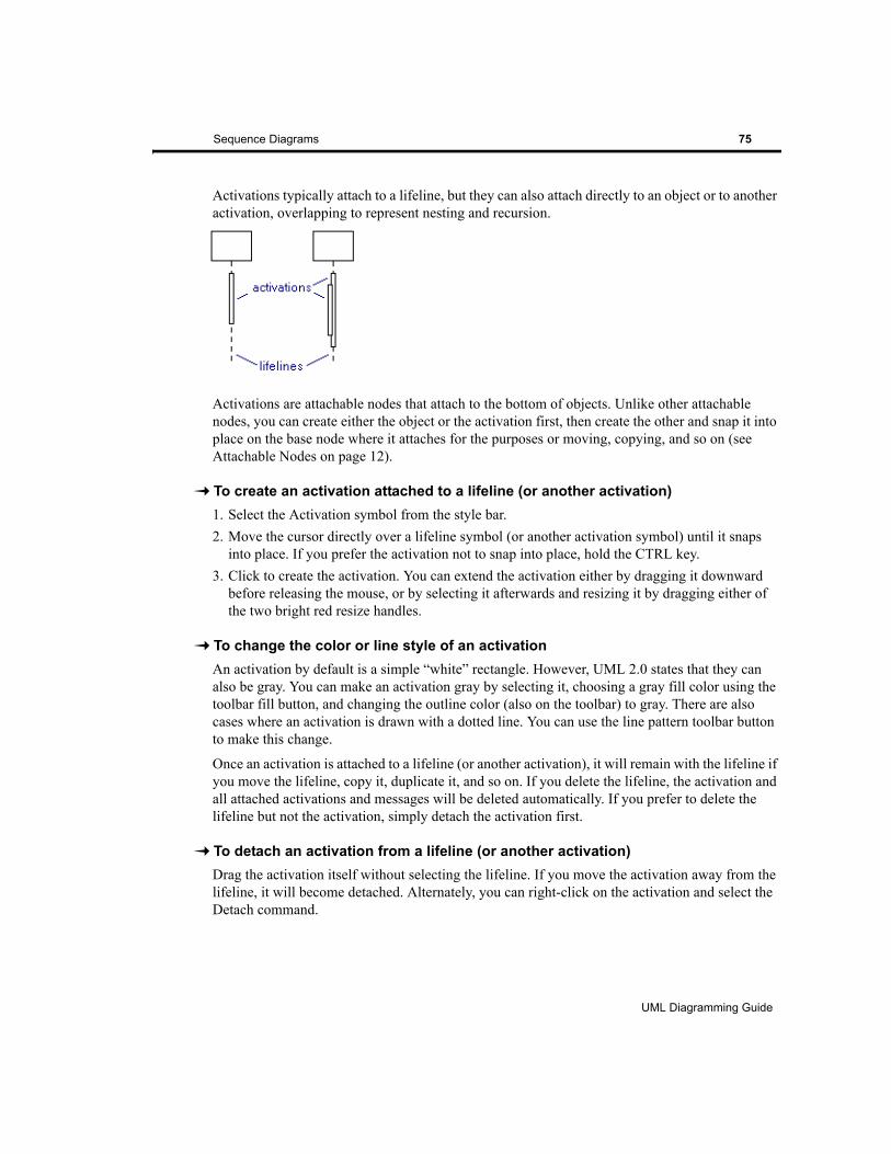
Sequence Diagrams 75
Activations typically attach to a lifeline, but they can also attach directly to an object or to another activation, overlapping to represent nesting and recursion.
Activations are attachable nodes that attach to the bottom of objects. Unlike other attachable nodes, you can create either the object or the activation first, then create the other and snap it into place on the base node where it attaches for the purposes or moving, copying, and so on (see Attachable Nodes on page 12).
To create an activation attached to a lifeline (or another activation)1. Select the Activation symbol from the style bar.2. Move the cursor directly over a lifeline symbol (or another activation symbol) until it snaps
into place. If you prefer the activation not to snap into place, hold the CTRL key.3. Click to create the activation. You can extend the activation either by dragging it downward
before releasing the mouse, or by selecting it afterwards and resizing it by dragging either of the two bright red resize handles.
To change the color or line style of an activationAn activation by default is a simple “white” rectangle. However, UML 2.0 states that they can also be gray. You can make an activation gray by selecting it, choosing a gray fill color using the toolbar fill button, and changing the outline color (also on the toolbar) to gray. There are also cases where an activation is drawn with a dotted line. You can use the line pattern toolbar button to make this change.
Once an activation is attached to a lifeline (or another activation), it will remain with the lifeline if you move the lifeline, copy it, duplicate it, and so on. If you delete the lifeline, the activation and all attached activations and messages will be deleted automatically. If you prefer to delete the lifeline but not the activation, simply detach the activation first.
To detach an activation from a lifeline (or another activation)Drag the activation itself without selecting the lifeline. If you move the activation away from the lifeline, it will become detached. Alternately, you can right-click on the activation and select the Detach command.
UML Diagramming Guide
EDGE Diagrammer User’s Guide
Page 75 of 96
Last Modified May 18, 2009 5:39 pm
Filename: S:\UFLOW\UMLDOC\UML Diagramming Guide.fm
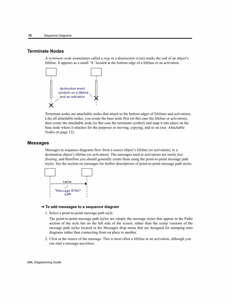
76 Sequence Diagrams
Terminate NodesA terminate node (sometimes called a stop or a destruction event) marks the end of an object’s lifeline. It appears as a small ‘X’ located at the bottom edge of a lifeline or an activation.
Terminate nodes are attachable nodes that attach to the bottom edges of lifelines and activations. Like all attachable nodes, you create the base node first (in this case the lifeline or activation), then create the attachable node (in this case the terminate symbol) and snap it into place on the base node where it attaches for the purposes or moving, copying, and so on (see Attachable Nodes on page 12).
MessagesMessages in sequence diagrams flow from a source object’s lifeline (or activation), to a destination object’s lifeline (or activation). The messages used in activations are rarely free floating, and therefore you should generally create them using the point-to-point message path styles. See the section on messages for further descriptions of point-to-point message path styles.
To add messages to a sequence diagram1. Select a point-to-point message path style.
The point-to-point message path styles are simply the message styles that appear in the Paths section of the style bar on the left side of the screen, rather than the stamp versions of the message path styles located in the Messages drop menu that are designed for stamping onto diagrams rather than connecting from on place to another.
2. Click at the source of the message. This is most often a lifeline or an activation, although you can start a message anywhere.
UML Diagramming Guide
EDGE Diagrammer User’s Guide - Beta Version
Page 76 of 96
Last Modified May 18, 2009 5:39 pm
Filename: S:\UFLOW\UMLDOC\UML Diagramming Guide.fm
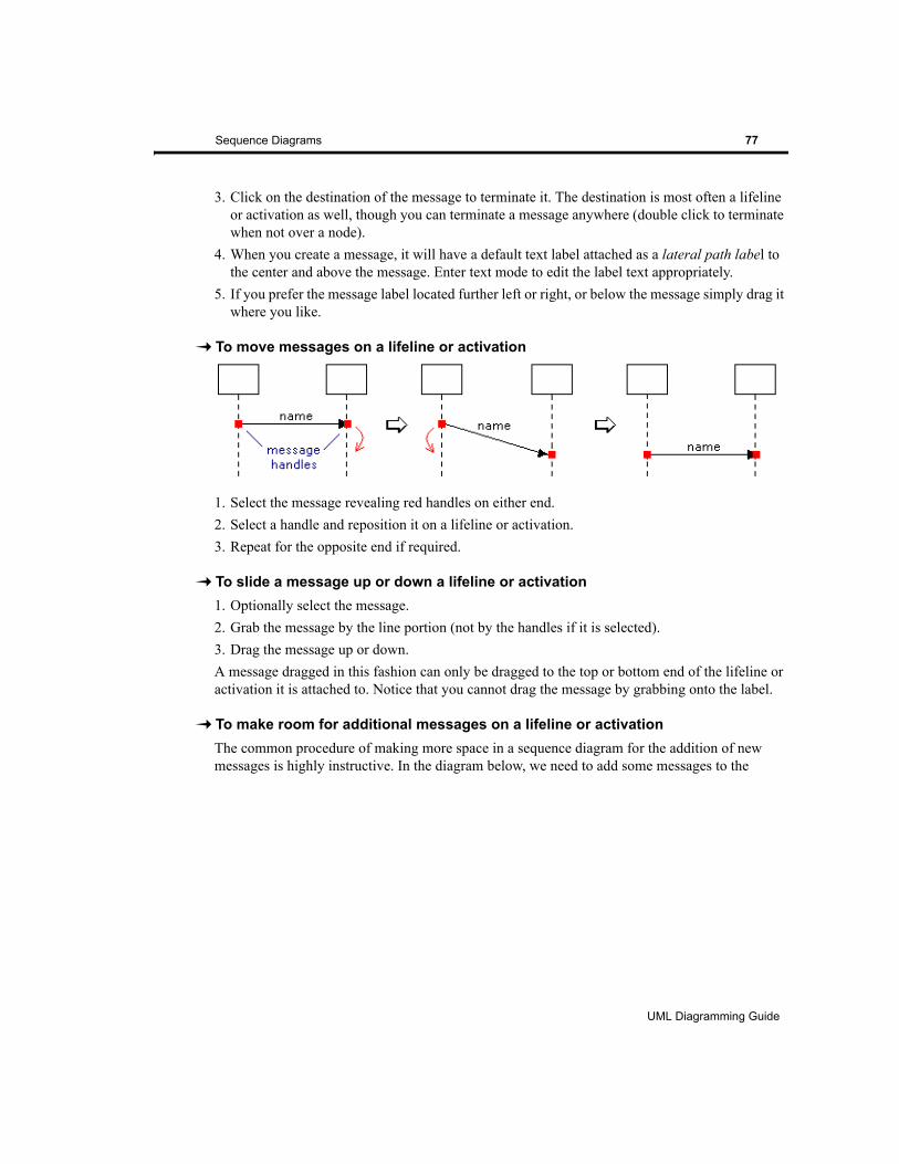
Sequence Diagrams 77
3. Click on the destination of the message to terminate it. The destination is most often a lifeline or activation as well, though you can terminate a message anywhere (double click to terminate when not over a node).
4. When you create a message, it will have a default text label attached as a lateral path label to the center and above the message. Enter text mode to edit the label text appropriately.
5. If you prefer the message label located further left or right, or below the message simply drag it where you like.
To move messages on a lifeline or activation
1. Select the message revealing red handles on either end.2. Select a handle and reposition it on a lifeline or activation.3. Repeat for the opposite end if required.
To slide a message up or down a lifeline or activation1. Optionally select the message.2. Grab the message by the line portion (not by the handles if it is selected).3. Drag the message up or down. A message dragged in this fashion can only be dragged to the top or bottom end of the lifeline or activation it is attached to. Notice that you cannot drag the message by grabbing onto the label.
To make room for additional messages on a lifeline or activationThe common procedure of making more space in a sequence diagram for the addition of new messages is highly instructive. In the diagram below, we need to add some messages to the
UML Diagramming Guide
EDGE Diagrammer User’s Guide
Page 77 of 96
Last Modified May 18, 2009 5:39 pm
Filename: S:\UFLOW\UMLDOC\UML Diagramming Guide.fm
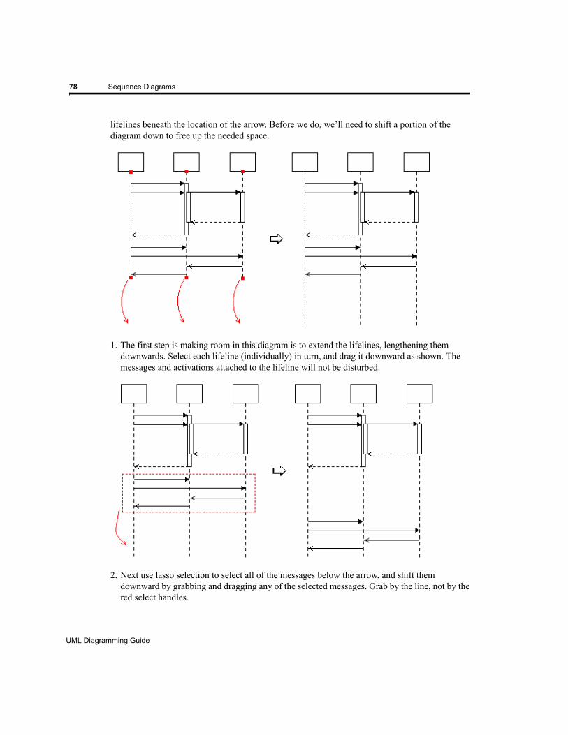
78 Sequence Diagrams
lifelines beneath the location of the arrow. Before we do, we’ll need to shift a portion of the diagram down to free up the needed space.
1. The first step is making room in this diagram is to extend the lifelines, lengthening them downwards. Select each lifeline (individually) in turn, and drag it downward as shown. The messages and activations attached to the lifeline will not be disturbed.
2. Next use lasso selection to select all of the messages below the arrow, and shift them downward by grabbing and dragging any of the selected messages. Grab by the line, not by the red select handles.
UML Diagramming Guide
EDGE Diagrammer User’s Guide - Beta Version
Page 78 of 96
Last Modified May 18, 2009 5:39 pm
Filename: S:\UFLOW\UMLDOC\UML Diagramming Guide.fm
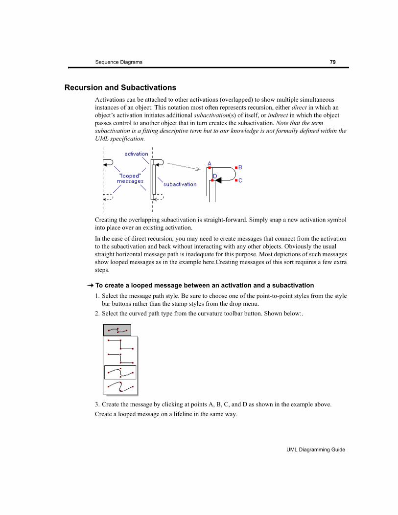
Sequence Diagrams 79
Recursion and SubactivationsActivations can be attached to other activations (overlapped) to show multiple simultaneous instances of an object. This notation most often represents recursion, either direct in which an object’s activation initiates additional subactivation(s) of itself, or indirect in which the object passes control to another object that in turn creates the subactivation. Note that the term subactivation is a fitting descriptive term but to our knowledge is not formally defined within the UML specification.
Creating the overlapping subactivation is straight-forward. Simply snap a new activation symbol into place over an existing activation.
In the case of direct recursion, you may need to create messages that connect from the activation to the subactivation and back without interacting with any other objects. Obviously the usual straight horizontal message path is inadequate for this purpose. Most depictions of such messages show looped messages as in the example here.Creating messages of this sort requires a few extra steps.
To create a looped message between an activation and a subactivation1. Select the message path style. Be sure to choose one of the point-to-point styles from the style
bar buttons rather than the stamp styles from the drop menu.2. Select the curved path type from the curvature toolbar button. Shown below:.
3. Create the message by clicking at points A, B, C, and D as shown in the example above.Create a looped message on a lifeline in the same way.
UML Diagramming Guide
EDGE Diagrammer User’s Guide
Page 79 of 96
Last Modified May 18, 2009 5:39 pm
Filename: S:\UFLOW\UMLDOC\UML Diagramming Guide.fm
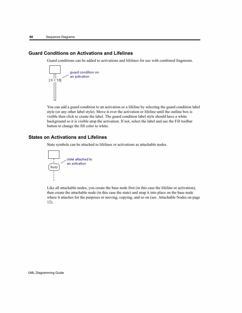
80 Sequence Diagrams
Guard Conditions on Activations and LifelinesGuard conditions can be added to activations and lifelines for use with combined fragments.
You can add a guard condition to an activation or a lifeline by selecting the guard condition label style (or any other label style). Move it over the activation or lifeline until the outline box is visible then click to create the label. The guard condition label style should have a white background so it is visible atop the activation. If not, select the label and use the Fill toolbar button to change the fill color to white.
States on Activations and LifelinesState symbols can be attached to lifelines or activations as attachable nodes.
Like all attachable nodes, you create the base node first (in this case the lifeline or activation), then create the attachable node (in this case the state) and snap it into place on the base node where it attaches for the purposes or moving, copying, and so on (see Attachable Nodes on page 12).
UML Diagramming Guide
EDGE Diagrammer User’s Guide - Beta Version
Page 80 of 96
Last Modified May 18, 2009 5:39 pm
Filename: S:\UFLOW\UMLDOC\UML Diagramming Guide.fm

CHAPTER10 STATE DIAGRAMS
This section describes diagramming techniques that are primarily applicable to State Diagrams.
Sample State Diagram
UML Diagramming Guide
EDGE Diagrammer User’s Guide
Page 81 of 96
Last Modified May 18, 2009 5:39 pm
Filename: S:\UFLOW\UMLDOC\UML Diagramming Guide.fm

82 State Diagrams
State Diagram Style Usage Tables
STATE DIAGRAM PATH STYLE USAGE
StyleName(s)
UML Construct(s) Appearance Description
Transition transition A transition from one state to another or the same state. A guard condition on the transition, usually represented by an attached path label, indicates the event that caused the transition.
STATE DIAGRAM NODE STYLE USAGE
StyleName(s)
UML Construct(s) Appearance Description
State state A condition in which each event has a consistent defined response.
State R2 state A state with a name compartment and a body compart-ment.
State R2 HidDecomp
state A state with added detail not shown.
State R3 state A state with a name compartment and two body com-partments.
Name Tab name tab A name tab is affixed to the left side of the top edge of a state symbol as an alternate method of naming a state.
Junction State junction state Chains transition segments into single run-to-comple-tion transition.
Sync State synchronization state
A synchronizing pseudo state connecting forks/joins on a concurrency boundary.
Branch/Merge branch,merge
Point where transitions merge asynchronously or branch based on guard conditions.
Decision decision This larger decision symbol is like a branch symbol but it can also contain text to help describe the branch con-ditions, reducing the complexity of the guard conditions on the outgoing flows.
UML Diagramming Guide
EDGE Diagrammer User’s Guide - Beta Version
Page 82 of 96
Last Modified May 18, 2009 5:39 pm
Filename: S:\UFLOW\UMLDOC\UML Diagramming Guide.fm
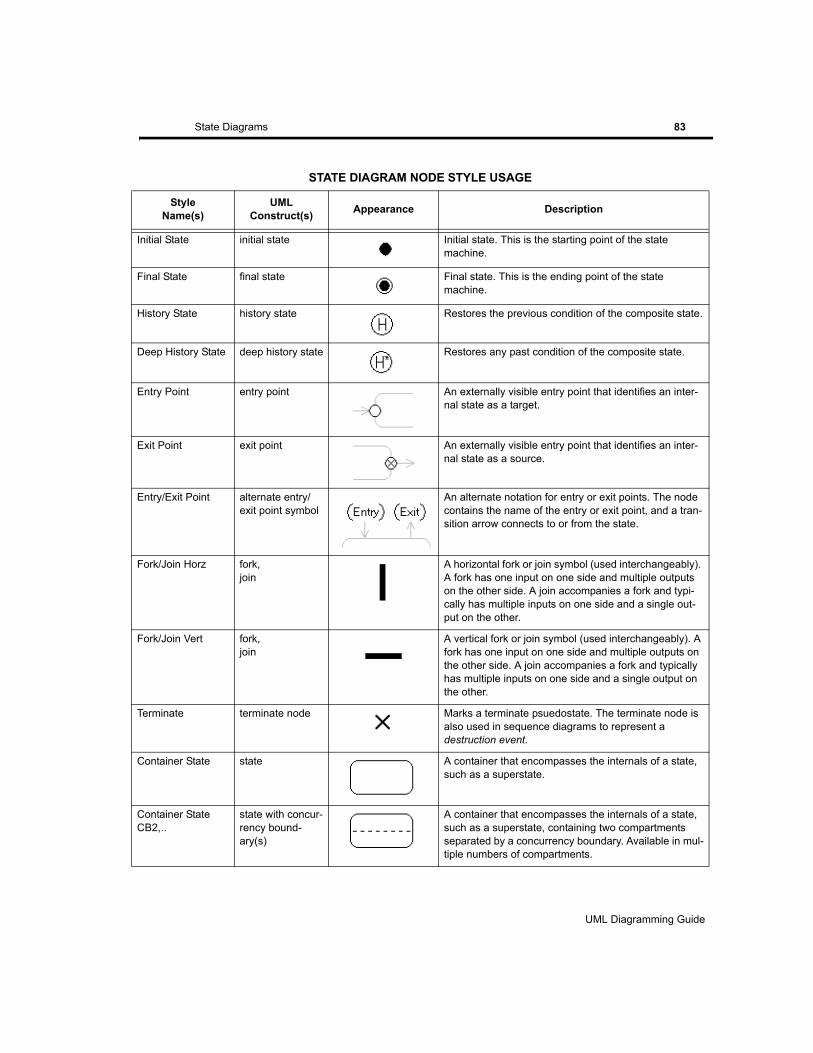
State Diagrams 83
Initial State initial state Initial state. This is the starting point of the state machine.
Final State final state Final state. This is the ending point of the state machine.
History State history state Restores the previous condition of the composite state.
Deep History State deep history state Restores any past condition of the composite state.
Entry Point entry point An externally visible entry point that identifies an inter-nal state as a target.
Exit Point exit point An externally visible entry point that identifies an inter-nal state as a source.
Entry/Exit Point alternate entry/exit point symbol
An alternate notation for entry or exit points. The node contains the name of the entry or exit point, and a tran-sition arrow connects to or from the state.
Fork/Join Horz fork,join
A horizontal fork or join symbol (used interchangeably). A fork has one input on one side and multiple outputs on the other side. A join accompanies a fork and typi-cally has multiple inputs on one side and a single out-put on the other.
Fork/Join Vert fork,join
A vertical fork or join symbol (used interchangeably). A fork has one input on one side and multiple outputs on the other side. A join accompanies a fork and typically has multiple inputs on one side and a single output on the other.
Terminate terminate node Marks a terminate psuedostate. The terminate node is also used in sequence diagrams to represent a destruction event.
Container State state A container that encompasses the internals of a state, such as a superstate.
Container State CB2,..
state with concur-rency bound-ary(s)
A container that encompasses the internals of a state, such as a superstate, containing two compartments separated by a concurrency boundary. Available in mul-tiple numbers of compartments.
STATE DIAGRAM NODE STYLE USAGE
StyleName(s)
UML Construct(s) Appearance Description
UML Diagramming Guide
EDGE Diagrammer User’s Guide
Page 83 of 96
Last Modified May 18, 2009 5:39 pm
Filename: S:\UFLOW\UMLDOC\UML Diagramming Guide.fm

84 State Diagrams
Superstates
A superstate is a state that has internal substates and contains a diagram of its inner workings. An obvious way to create a superstate is to create a normal state, enlarge it, and add the substate diagram within. However, we strongly recommend that you instead create the superstate using a State Container. A State Container (like any container) is more that a large state. For one thing it is transparent so that you need not be concerned whether the internals are in front of it or behind it. It is transparent so that it is selectable only by its outline or its text area (if any), making it easier to work on the internals without accidentally selecting the container. Containers also have a number of other minor behavioral differences designed for exactly this purpose.
The substate diagram within a superstate is simply a normal state diagram and requires no special techniques.
Concurrency Boundaries
A concurrency boundary is a divider drawn within a superstate that separates two or more portions of the state that operate concurrently. It is represented as a simple dashed line dividing the superstate symbol. Although the tool does not explicitly support this notation as part of the state symbol, you can easily add your own concurrency boundary anywhere within a superstate symbol. To create the concurrency boundary, use a path of style Dashed Divider (obtain this by clicking on the Paths button in the style bar and locating it in the Nonstandard category drop menu).
UML Diagramming Guide
EDGE Diagrammer User’s Guide - Beta Version
Page 84 of 96
Last Modified May 18, 2009 5:39 pm
Filename: S:\UFLOW\UMLDOC\UML Diagramming Guide.fm
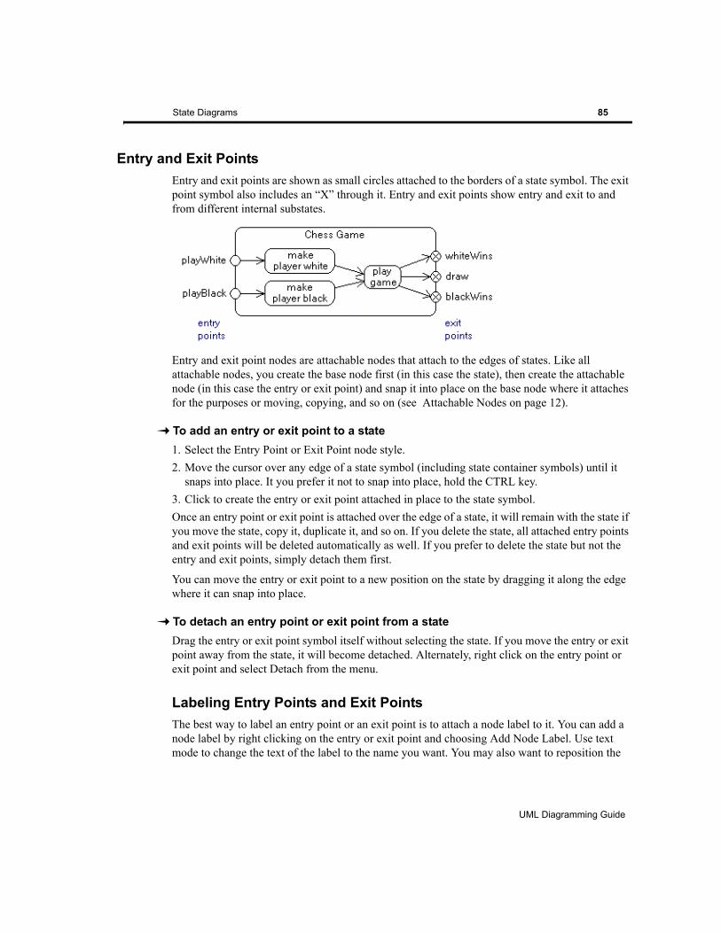
State Diagrams 85
Entry and Exit PointsEntry and exit points are shown as small circles attached to the borders of a state symbol. The exit point symbol also includes an “X” through it. Entry and exit points show entry and exit to and from different internal substates.
Entry and exit point nodes are attachable nodes that attach to the edges of states. Like all attachable nodes, you create the base node first (in this case the state), then create the attachable node (in this case the entry or exit point) and snap it into place on the base node where it attaches for the purposes or moving, copying, and so on (see Attachable Nodes on page 12).
To add an entry or exit point to a state1. Select the Entry Point or Exit Point node style.2. Move the cursor over any edge of a state symbol (including state container symbols) until it
snaps into place. It you prefer it not to snap into place, hold the CTRL key.3. Click to create the entry or exit point attached in place to the state symbol.Once an entry point or exit point is attached over the edge of a state, it will remain with the state if you move the state, copy it, duplicate it, and so on. If you delete the state, all attached entry points and exit points will be deleted automatically as well. If you prefer to delete the state but not the entry and exit points, simply detach them first.
You can move the entry or exit point to a new position on the state by dragging it along the edge where it can snap into place.
To detach an entry point or exit point from a stateDrag the entry or exit point symbol itself without selecting the state. If you move the entry or exit point away from the state, it will become detached. Alternately, right click on the entry point or exit point and select Detach from the menu.
Labeling Entry Points and Exit PointsThe best way to label an entry point or an exit point is to attach a node label to it. You can add a node label by right clicking on the entry or exit point and choosing Add Node Label. Use text mode to change the text of the label to the name you want. You may also want to reposition the
UML Diagramming Guide
EDGE Diagrammer User’s Guide
Page 85 of 96
Last Modified May 18, 2009 5:39 pm
Filename: S:\UFLOW\UMLDOC\UML Diagramming Guide.fm
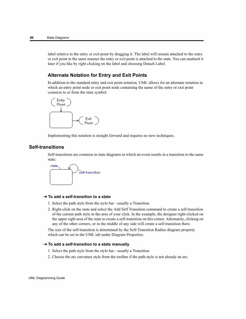
86 State Diagrams
label relative to the entry or exit point by dragging it. The label will remain attached to the entry or exit point in the same manner the entry or exit point is attached to the state. You can unattach it later if you like by right clicking on the label and choosing Detach Label.
Alternate Notation for Entry and Exit PointsIn addition to the standard entry and exit point notation, UML allows for an alternate notation in which an entry point node or exit point node containing the name of the entry or exit point connects to or from the state symbol.
Implementing this notation is straight forward and requires no new techniques.
Self-transitionsSelf-transitions are common in state diagrams in which an event results in a transition to the same state.
To add a self-transition to a state1. Select the path style from the style bar - usually a Transition.2. Right-click on the state and select the Add Self Transition command to create a self-transition
of the current path style in the area of your click. In the example, the designer right-clicked on the upper right area of the state to create a self-transition on this corner. Alternately, clicking on any of the other corners, or in the middle of any side will create a self-transition there.
The size of the self-transition is determined by the Self-Transition Radius diagram property which can be set in the UML tab under Diagram Properties.
To add a self-transition to a state manually1. Select the path style from the style bar - usually a Transition.2. Choose the arc curvature style from the toolbar if the path style is not already an arc.
UML Diagramming Guide
EDGE Diagrammer User’s Guide - Beta Version
Page 86 of 96
Last Modified May 18, 2009 5:39 pm
Filename: S:\UFLOW\UMLDOC\UML Diagramming Guide.fm
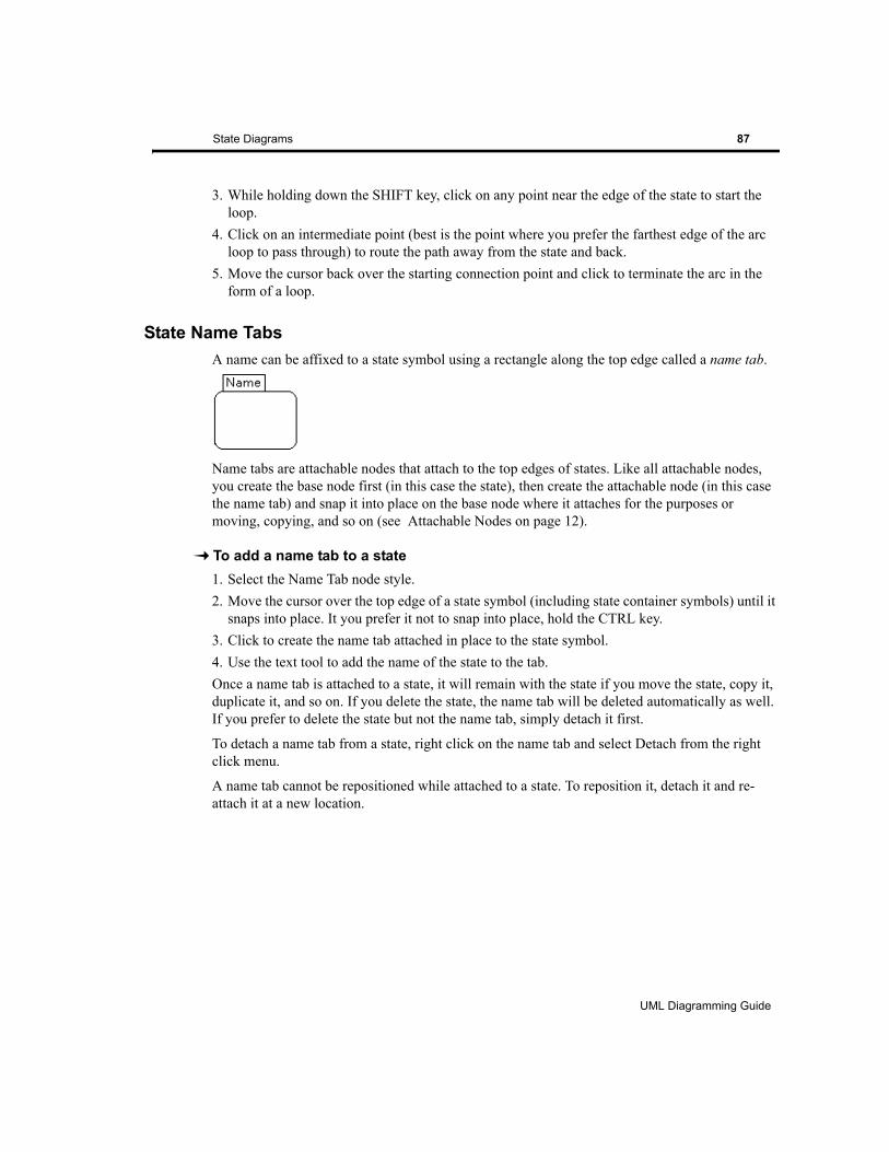
State Diagrams 87
3. While holding down the SHIFT key, click on any point near the edge of the state to start the loop.
4. Click on an intermediate point (best is the point where you prefer the farthest edge of the arc loop to pass through) to route the path away from the state and back.
5. Move the cursor back over the starting connection point and click to terminate the arc in the form of a loop.
State Name TabsA name can be affixed to a state symbol using a rectangle along the top edge called a name tab.
Name tabs are attachable nodes that attach to the top edges of states. Like all attachable nodes, you create the base node first (in this case the state), then create the attachable node (in this case the name tab) and snap it into place on the base node where it attaches for the purposes or moving, copying, and so on (see Attachable Nodes on page 12).
To add a name tab to a state1. Select the Name Tab node style.2. Move the cursor over the top edge of a state symbol (including state container symbols) until it
snaps into place. It you prefer it not to snap into place, hold the CTRL key.3. Click to create the name tab attached in place to the state symbol.4. Use the text tool to add the name of the state to the tab.Once a name tab is attached to a state, it will remain with the state if you move the state, copy it, duplicate it, and so on. If you delete the state, the name tab will be deleted automatically as well. If you prefer to delete the state but not the name tab, simply detach it first.
To detach a name tab from a state, right click on the name tab and select Detach from the right click menu.
A name tab cannot be repositioned while attached to a state. To reposition it, detach it and re-attach it at a new location.
UML Diagramming Guide
EDGE Diagrammer User’s Guide
Page 87 of 96
Last Modified May 18, 2009 5:39 pm
Filename: S:\UFLOW\UMLDOC\UML Diagramming Guide.fm

88 State Diagrams
UML Diagramming Guide
EDGE Diagrammer User’s Guide - Beta Version
Page 88 of 96
Last Modified May 18, 2009 5:39 pm
Filename: S:\UFLOW\UMLDOC\UML Diagramming Guide.fm
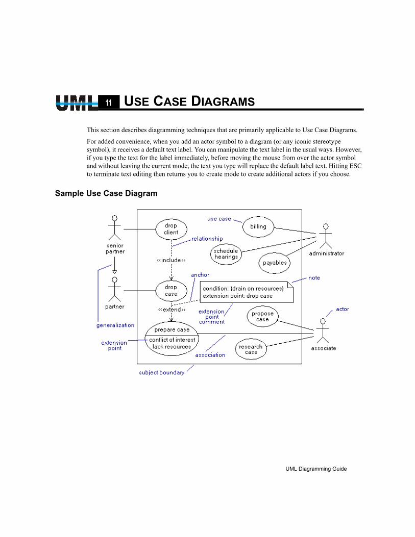
CHAPTER11 USE CASE DIAGRAMS
This section describes diagramming techniques that are primarily applicable to Use Case Diagrams.
For added convenience, when you add an actor symbol to a diagram (or any iconic stereotype symbol), it receives a default text label. You can manipulate the text label in the usual ways. However, if you type the text for the label immediately, before moving the mouse from over the actor symbol and without leaving the current mode, the text you type will replace the default label text. Hitting ESC to terminate text editing then returns you to create mode to create additional actors if you choose.
Sample Use Case Diagram
UML Diagramming Guide
EDGE Diagrammer User’s Guide
Page 89 of 96
Last Modified May 18, 2009 5:39 pm
Filename: S:\UFLOW\UMLDOC\UML Diagramming Guide.fm
90 Use Case Diagrams
Use Case Diagram Style Usage Tables
USE CASE DIAGRAM PATH STYLE USAGE
StyleName(s)
UML Construct(s) Appearance Description
Association association An association between an actor and a use case.
Relationship relationship Connects one use case to another to show a relationship (includes or extends).
Generalization generalization Shows a generalization relationship between actors (inherit-ance). The arrow points toward the less general type.
USE CASE DIAGRAM NODE STYLE USAGE
StyleName(s)
UML Construct(s) Appearance Description
Use Case use case A common use case symbol.
Use Case Ext extended use case
An extended use case.
Actor actor An external person, process, or thing that interacts with a system.
Actor System system actor A more generalized representation of an actor. Used to dis-tinguish non-user actors (such as systems) from the stan-dard actor symbol. Graphics and other symbols are acceptable as well.
SubjectBoundary
subject boundary A rectangular container that shows the boundaries of the subject (system). Any container can be used for this pur-pose.
UML Diagramming Guide
EDGE Diagrammer User’s Guide - Beta Version
Page 90 of 96
Last Modified May 18, 2009 5:39 pm
Filename: S:\UFLOW\UMLDOC\UML Diagramming Guide.fm
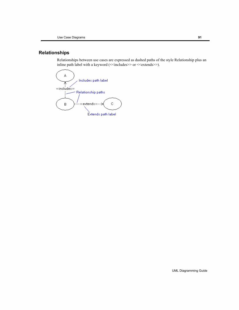
Use Case Diagrams 91
RelationshipsRelationships between use cases are expressed as dashed paths of the style Relationship plus an inline path label with a keyword (<<includes>> or <<extends>>).
UML Diagramming Guide
EDGE Diagrammer User’s Guide
Page 91 of 96
Last Modified May 18, 2009 5:39 pm
Filename: S:\UFLOW\UMLDOC\UML Diagramming Guide.fm

92 Use Case Diagrams
UML Diagramming Guide
EDGE Diagrammer User’s Guide - Beta Version
Page 92 of 96
Last Modified May 18, 2009 5:39 pm
Filename: S:\UFLOW\UMLDOC\UML Diagramming Guide.fm

CHAPTER12 UNSUPPORTED
Some UML notation is not specifically supported by features of this version of the software. In most of these cases, the notation is minor or infrequently used, or it can be easily simulated using generic drawing capabilities. The most important omissions will obviously be candidates for addition in future releases.
Timing DiagramsTiming diagrams are included as part of the UML 2.0 specification but are not directly supported by this release of the software. While there is no timing diagram template or symbols and features to conveniently support constructing timing diagrams, you can use the standard templates and the generic symbols (lines and basic shapes) to create simple timing diagrams without too much difficulty.
Parameter SetsParameter set notation is not supported directly. Parameter set notation consists of rectangles that encompass a set of pins. As a work-around you can add a generic rectangle for this purpose. It will just lack the automatic attachment capabilities and will require greater effort to maintain.
Explicit Directions on Input and Output PinsInput and output pins can be distinguished explicitly by adding small arrow heads to the pin symbols. The software does not support this notation. You can of course use the convention of left=input right=output, or you can add direction indication using labels.
General Ordering PathThe general ordering path style is not supported. It appears as a dashed line with an arrow in the center (rather than at the end). If necessary, you can create such a path on a case-by-case basis using flow symbols feature (see the main user guide).
UML Diagramming Guide
EDGE Diagrammer User’s Guide
Page 93 of 96
Last Modified May 18, 2009 5:39 pm
Filename: S:\UFLOW\UMLDOC\UML Diagramming Guide.fm
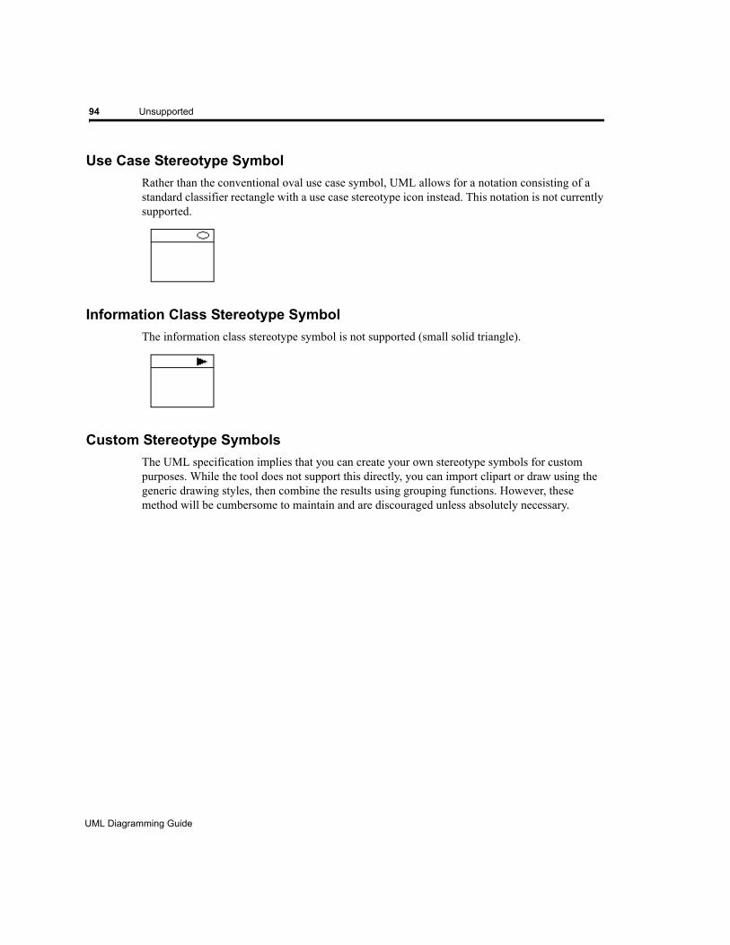
94 Unsupported
Use Case Stereotype SymbolRather than the conventional oval use case symbol, UML allows for a notation consisting of a standard classifier rectangle with a use case stereotype icon instead. This notation is not currently supported.
Information Class Stereotype SymbolThe information class stereotype symbol is not supported (small solid triangle).
Custom Stereotype SymbolsThe UML specification implies that you can create your own stereotype symbols for custom purposes. While the tool does not support this directly, you can import clipart or draw using the generic drawing styles, then combine the results using grouping functions. However, these method will be cumbersome to maintain and are discouraged unless absolutely necessary.
UML Diagramming Guide
EDGE Diagrammer User’s Guide - Beta Version
Page 94 of 96
Last Modified May 18, 2009 5:39 pm
Filename: S:\UFLOW\UMLDOC\UML Diagramming Guide.fm
CHAPTER13 REFERENCES
The following are reference publications used in compiling this document and the features of the software. The bracketed code preceding each is used within the text to cross reference the publications.
[SPEC] UML 2.0 Superstructure Final Adopted specification (formal/05-07-04, August 1995) Object Management Group (http://www.omg.org)
[UD3] UML Distilled Third Edition Martin Fowler, Addison-Wesley, 2004
[BIB] UML Bible Tom Pender, Wiley Publishing, Inc., 2003
[REF2] The Unified Modeling Language Reference Manual, Second Edition James Rumbaugh, Ivar Jacobson, and Grady Booch, Addison-Wesley, 2005
UML Diagramming Guide
EDGE Diagrammer User’s Guide
Page 95 of 96
Last Modified May 18, 2009 5:39 pm
Filename: S:\UFLOW\UMLDOC\UML Diagramming Guide.fm

96 References
UML Diagramming Guide
EDGE Diagrammer User’s Guide - Beta Version
Page 96 of 96
Last Modified May 18, 2009 5:39 pm
Filename: S:\UFLOW\UMLDOC\UML Diagramming Guide.fm
Index 97
INDEX
Aaction 26action node 29action state 26activation 72, 74, 75active class 37active object 37, 73activity 26activity diagram 25actor 38aggregation 36alternate entry point symbol 83anchor 15, 43anchor point 15angle brackets 11assembly connector 55, 58association 36, 40association class 43association constraint 43association direction indicator 42association end label 41association multiplicities 41association names 42, 44association path 44, 51association terminator 40asynchronous message 48, 72attachable node 12, 13, 31, 44, 45, 59, 74, 75, 76, 80, 85, 87
Bball and socket notation 56base node 12, 13bidirectional association 36bidirectional navigability 40
binary association 43boundary 38branch 27, 29, 82branch node 29
Cchangeability 41class diagram 35class/object diagram 35classifier 60collaboration 39combined fragment 73comments 15complex port 55component 55, 60component diagram 53composite structure diagram 63composition 36concurrency boundary 84condition 29conditional branch 29connector 32constraint 41, 43, 44container 16containment 36, 48, 68control 38conventions (used in this guide) 9Creating 60
Ddata flow 29, 48decision 27, 29, 82decision node 29deep history state 83dependency 36, 68deployment diagram 53destruction event 73, 76, 83
UML Diagramming Guide
98 Index
detach 14direction indicator 42, 44directional aggregation 36directional association 36, 40directional composition 36drawing 24
Eedge 26end label 41entity 38entry point 83, 85exception parameter 27, 32execution specification 74exit point 83, 85exit points 85expansion node 31expansion region 27, 29, 30extensions 23
Ffinal state 27, 83flow 26flow final 27flow label 19, 41flow symbol 44focus of control 72, 74fork 26, 27, 28, 83found message 48, 72frames 17free floating messages 49free pin 30
Ggeneral ordering path 93general techniques 11generalization 36, 68
guard conditions (on activations and life-lines) 80guillemets 11
Hhidden port 60history state 83
Iinitial state 27, 83inline path label 18, 42, 51intefaces 60interaction overview diagram 65interface 35, 47, 56interface assembly connector 58interface label 58interface specifier 41internal icon 23interruptible activity region 33
Jjagged flow 33join 26, 27, 28, 83junction state 82
Kkeys 9keywords 11
Llabeling interfaces 58labeling messages 51labeling ports 60, 85lateral path label 18, 42, 43, 51lifeline 72, 73, 75listbox pin 27, 31lollipop interface 56
UML Diagramming Guide
Index 99
looped message 51, 79lost message 48, 72
Mmerge 27, 82message label 51messages 49
point-to-point 49stamped 49, 50
messages (in sequence diagram) 76model 68moving interfaces 58multiplicities 41, 44
Nn’ary association 43n’ary associator 38n’ary associator node 43name tab 82, 87navigability 40node 55nonstandard symbols 23note 15
Oobject 72object diagram 35object flow 26, 28object flow node 29object flow state 26, 28
Ppackage 60, 68package diagram 67parameter list 45parameter sets 93part 72
partitions 35, 47path label 18path trees 19, 20Paths 49pin 27, 29point-to-point messages 49, 76port 35, 47, 55, 57, 59, 60private port 60provided interface 55, 56provided interface assembly 55, 57
Qqualifier 39, 44, 45
Rrealization 36, 68receive event 26recursion 79reply 48, 72required interface 55, 56required interface assembly 55, 57role 41, 72, 73rolename 41, 44
Sself-transition 86send event 26stamped messages 49, 50state 73, 82state container 84state diagram 81stop 76subactivation 79subactivity 26subsystem 68superstate 84symbols (used in this guide) 9
UML Diagramming Guide
100 Index
synchronization state 82synchronous message 48, 72
Ttemplate 39, 45terminate 73terminate node 73, 76, 83terminate psuedostate 83time signal 27timing diagram 93to interface path 56transition 82trees 69
Uunidirectional association 40unnavigable association 36unsupported UML 93use case diagram 89
UML Diagramming Guide

Index 101
UML Diagramming Guide

102 Index
UML Diagramming Guide