unbalanced snow loads on arched roofs - · pdf file1 parametric studies of unbalanced snow...
TRANSCRIPT

1
PARAMETRIC STUDIES OF UNBALANCED SNOW LOADS ON ARCHED ROOFS
F. M. Hochstenbach1, P. A. Irwin1, and S. L. Gamble1
1 Rowan Williams Davies & Irwin, Inc., 650 Woodlawn Road West, Guelph, Ontario, Canada N1K 1B8; PH (519) 823-1311; FAX (519) 823-1316; email:[email protected]
Abstract
Building codes and standards often indicate that unbalanced loading of arched roofs need not be considered if the roof is flat enough. They typically provide a threshold value for arch height as the criterion. However, real snow doesn’t behave differently slightly above the threshold than slightly below. Recent building collapses have brought this issue into discussion since buildings designed below the threshold still produced significant unbalanced loads. The purpose of this research project was to investigate the lower bound of arched roof geometry and to compare the results with provisions of the 1995 National Building Code of Canada (NBCC) and the American Society of Civil Engineers Standard (ASCE 7-2002). Parametric Finite Area Element (FAE) snow loading simulations (using methodology described by Irwin, Gamble and Taylor, 1995) were performed on a range of arched roof geometries using a range of meteorological data sets. The results indicated that, in certain situations, significant unbalanced loading could be expected for roofs that would otherwise be treated as flat, warranting special consideration in the appropriate codes and standards. The study also indicated that the azimuthal orientation of the roof relative to the prevailing winds plays a major role in some cases.
Introduction
It has long been understood that snow drifting on arched roofs can produce significantly more snow on one side of the roof than the other. In the 1995 NBCC, specific unbalanced design loads are recommended for roofs where the rise (h) to span (b) ratio exceeds 0.10 (h/b > 0.1). Similarly in the 2002 edition of the ASCE 7, unbalanced loads on curved roofs need to be taken into account if the slope of a straight line from the eave to the crown is greater than 10o (h/b > 0.088). Recently there have been occurrences of structural failure of arched roofs in Canada with h/b ratios less than 0.10. This has led to discussion of potential revisions to the codes and standards to account for flatter roofs where unbalanced loads could still form.
This paper describes Finite Area Element (FAE) studies of unbalanced snow loads on arched roofs with a range of arch geometries and a comparison of the results with the equivalent loading patterns recommended by the NBCC and the ASCE building standard.
Test Methodology
General: The present method used to determine quantitative site and geometry specific design snow loads is the FAE method. This method is essentially a detailed computer simulation of the hour-by- hour deposition, drifting and melting of snow on
2
the roof under study. The absorption of rain and meltwater into the snowpack is also accounted for. Entire winters are simulated, including the cumulative effects of successive storms, drifting events and melting periods. The method uses wind tunnel data on the surface wind velocity field over the roof, combined with historical meteorological records such as daily snowfall, hourly snowfall intensity flags, hourly wind speeds and directions, rainfall, temperature, and cloud cover.
The FAE method has been used to determine design snow loads on over 70 roofs in North America, South America, Asia and Europe, and was also used in previous research, (Irwin, Gamble, and Taylor, 1995), funded by the National Research Council of Canada to develop improved snow load provisions for large flat roofs, which were incorporated into the 1995 edition of the NBCC. Due to space limitations, a more detailed description of the FAE method has not been included, but has been discussed in previous papers, (Irwin and Williams 1983); (Irwin and Gamble 1987); (Irwin and Gamble 1988); (Gamble, Kochanski and Irwin 1992); (Irwin, Gamble, Retzlaff and Taylor 1992); and (Irwin, Gamble, Hunter and Kochanski 1993).
The following sections present the basic components required to complete the FAE study in the present case.
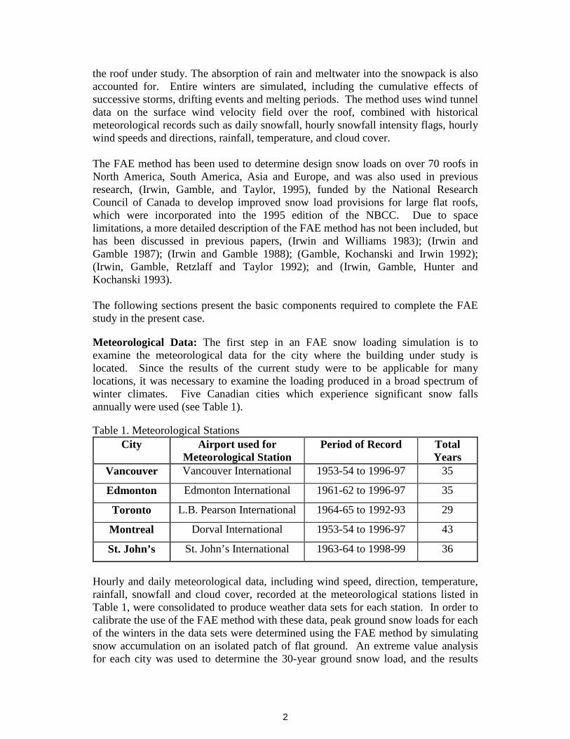
Meteorological Data: The first step in an FAE snow loading simulation is to examine the meteorological data for the city where the building under study is located. Since the results of the current study were to be applicable for many locations, it was necessary to examine the loading produced in a broad spectrum of winter climates. Five Canadian cities which experience significant snow falls annually were used (see Table 1).
Table 1. Meteorological StationsCity Airport used for
Meteorological StationPeriod of Record Total
YearsVancouver Vancouver International 1953-54 to 1996-97 35
Edmonton Edmonton International 1961-62 to 1996-97 35
Toronto L.B. Pearson International 1964-65 to 1992-93 29
Montreal Dorval International 1953-54 to 1996-97 43
St. John’s St. John’s International 1963-64 to 1998-99 36
Hourly and daily meteorological data, including wind speed, direction, temperature, rainfall, snowfall and cloud cover, recorded at the meteorological stations listed in Table 1, were consolidated to produce weather data sets for each station. In order to calibrate the use of the FAE method with these data, peak ground snow loads for each of the winters in the data sets were determined using the FAE method by simulating snow accumulation on an isolated patch of flat ground. An extreme value analysis for each city was used to determine the 30-year ground snow load, and the results

3
were compared with those published in the NBCC. The 30-year value is specified in the NBCC. Table 2 shows the comparison. Note that the FAE loads contain both rain and snow components.
Table 2. Ground Snow Calibration
LocationFAE Simulated30 Yr. Ground
Snow Load
NBCC Snow Component
Ss
NBCC RainComponent
Sr
Vancouver 0.82 kPa / 17 psf 1.6 kPa / 33 psf 0.2 kPa / 4 psf
Edmonton 1.77 kPa / 37 psf 1.6 kPa / 33 psf 0.1 kPa / 2 psf
Toronto 1.32 kPa / 28 psf 1.0 kPa / 21 psf 0.4 kPa / 8 psf
Montreal 2.83 kPa / 59 psf 2.4 kPa / 50 psf 0.4 kPa / 8 psf
St. John’s 3.16 kPa / 66 psf 2.6 kPa / 54 psf 0.6 kPa / 12 psf
The above table also includes values of Ss and Sr obtained from the NBCC, for comparison purposes. With the exception of Vancouver, the values match well with those provided by the NBCC. For Vancouver, past experience has indicated that the snow accumulations vary dramatically with location relative to the ocean and with elevation changes, and that the design snow load provided in the NBCC is necessarily conservative to account for this variability. Having verified the applicability of the approach using ground snow loads, the next step was to predict the distribution of snow loads on a range of arched roofs.
Wind Tunnel Models: To compute snow drifting rates, the FAE method requires knowledge of the wind velocity patterns over the roof. These velocity patterns were obtained through wind tunnel tests in one of RWDI’s boundary layer wind tunnels using 1:100 scale models of the arched roofs. For this research project, five roofs were modeled in order to examine the potential for unbalanced snow loads on roofs with a range of arch geometries. Models with the following geometry were constructed.
Table 3. Model Roofsh/b Ratio(NBCC)
Eave-Crown Slope (ASCE)
Riseh
Spanb
LengthL
0.05 5.7o 2m / 6.5ft 40m / 131ft 80m / 262ft
0.075 8.5o 2.97m / 9.7ft 39.67m / 130ft 80m / 262ft
0.1 11.3o 3.92m / 12.9ft 39.2m / 129ft 80m / 262ft
0.125 14.0o 4.83m / 15.8ft 38.67m / 127ft 80m / 262ft
0.15 16.7o 5.7m / 18.7ft 38m / 125 ft 80m / 262ft

4
Figure 1 shows one of the study models in RWDI’s wind tunnel. The roof of each of these five models was instrumented with 64 surface velocity vector sensors, (Gamble, Kochanski and Irwin (1992). The characteristic wind flow patterns were measured over the surface of the roof by these sensors, for 24 wind directions in 15o
increments. Using the symmetry of the roof, the data for each sensor were mirrored in both main building axes to create the equivalent of 256 sensors on each roof. These data were then used for the FAE simulation. Figure 2 shows the Finite Area Element Grid.
Figure 1. Study Model in Wind Tunnel Figure 2. FAE Grid
Wind Tunnel Simulation of Approaching Wind: The boundary layer wind tunnel is capable of simulating both the mean speed and turbulence characteristics of ambient wind flows over the site as they vary with height above grade. Since unbalanced loading of an arched roof is a function of the wind driving snow across the roof, the more exposed, the greater the potential for unbalanced loads. Therefore open terrain, which produced an exposed condition, was assumed for all of the current studies.
Finite Area Element Model: The basic concept of an FAE study is to divide the roof into a large number of finite area elements (see Figure 2). For the current research, each of the five roof geometries was divided into 480 area elements. The FAE simulation process computes the movement of drifting snow between adjacent elements of the grid. The wind tunnel-derived velocity data were interpolated to provide a full velocity field for each of the nodes (corners) of the finite area elements. The velocity field was used to compute the drifting of snow from element to element for each hour simulated.
As discussed above, in order to examine the potential for unbalanced snow loads on roofs with a range of h/b ratios, five study models were built (Table 3). However, all of these models had roof spans of roughly 40 m (130 ft). There was concern that an arched roof with significantly longer or shorter span may behave differently. To study this, ten more computer models were created, five with a span of 20 m (65 ft), and five with a span of 80 m (260 ft), each having the same h/b ratios as the original

five 40 m span roofs. Because of this geometric similarity, the wind tunnel data in the form of velocity coefficients and local direction vectors for the 40 m models were assumed to be applicable for the other models as well.
Load Cases: When simulating the accumulation and depletion of snow loads on the arched roofs, the loading pattern of interest was the difference in load between the two sides of each arched roof. To ensure that these loading situations were reported by the FAE analysis, load cases or patterns were defined prior to carrying out the simulation. For this study, two unbalanced loading patterns were defined: a uniform unbalanced load (simple difference between halves), and a weighted unbalanced load (emphasising 1/4-chord loading, see Figure 3). To reduce the influence of winds wrapping around the ends of the roof, only the middle portion of the roof was included in these load cases.
Figure 3
During the houcases were contprevious maximupdated and thTherefore, at thvalue for each lof loading on analysed using ground snow.
Arched-Roof Bproduced by snThis produces fdeposit in the lare certain winoccur more freqsuch that these be realized. Ifunbalanced loarelative to the loads. In order
Unbalanced Load Case = load B - load A
Wind Along Arch
AB
5
r-by- hour simulations of snow ainually computed. If the currenum for that roof for that parti
e pattern of snow loads on the end of each year of simulatioad case, the date and time of othe entire roof at that time. extreme value fitting technique
uilding Orientation: Unbalancowfall with, or followed by, wilow deceleration and causes sn
eeward side of the arch. For and directions that do not occur auently, accompanied by significpredominant winds flow across the roof is orientated such thding can be very small. Therprevailing winds plays an impo to account for this, parametric
Wind Across Arch
Figure 4
ccumulation on the roofs, the two load t unbalanced load was greater than the cular winter, the maximum value was e roof was saved for later analysis.
on, the FAE process produced a peak ccurrence of the peak, and the pattern This information was subsequently s in the same way as was done for the
ed loads on arched roofs are generally nd blowing across the arch (Figure 4). ow drifted from the windward side to y particular geographic location, there s often and other wind directions that ant snowfalls. If the roof is orientated
the arch, higher unbalanced loads can at these winds flow along the arch,
efore, the orientation of the building rtant part in the resulting unbalanced runs were performed for all five cities
6
by rotating the building azimuthally through 180o, in 15o increments, to find the orientation that produced the greatest unbalanced load on each roof under study.
Example Load Cases
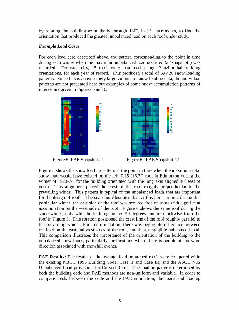
For each load case described above, the pattern corresponding to the point in time during each winter when the maximum unbalanced load occurred (a “snapshot”) was recorded. For each city, 15 roofs were examined, using 13 azimuthal building orientations, for each year of record. This produced a total of 69,420 snow loading patterns. Since this is an extremely large volume of snow loading data, the individual patterns are not presented here but examples of some snow accumulation patterns of interest are given in Figures 5 and 6.
Figure 5. FAE Snapshot #1 Figure 6. FAE Snapshot #2
Figure 5 shows the snow loading pattern at the point in time when the maximum total snow load would have existed on the h/b=0.15 (16.7o) roof in Edmonton during the winter of 1973-74, for the building orientated with the long axis aligned 30o east of north. This alignment placed the crest of the roof roughly perpendicular to the prevailing winds. This pattern is typical of the unbalanced loads that are important for the design of roofs. The snapshot illustrates that, at this point in time during this particular winter, the east side of the roof was scoured free of snow with significant accumulation on the west side of the roof. Figure 6 shows the same roof during the same winter, only with the building rotated 90 degrees counter-clockwise from the roof in Figure 5. This rotation positioned the crest line of the roof roughly parallel to the prevailing winds. For this orientation, there was negligible difference between the load on the east and west sides of the roof, and thus, negligible unbalanced load. This comparison illustrates the importance of the orientation of the building to the unbalanced snow loads, particularly for locations where there is one dominant wind direction associated with snowfall events.
FAE Results: The results of the average load on arched roofs were compared with: the existing NBCC 1995 Building Code, Case II and Case III; and the ASCE 7-02 Unbalanced Load provisions for Curved Roofs. The loading patterns determined by both the building code and FAE methods are non-uniform and variable. In order to compare loads between the code and the FAE simulation, the loads and loading

7
patterns were calculated and then averaged over the roof area of one half of the roof. For example, a loading pattern varying linearly from 0 kPa at the crest to 2 kPa at the eave would produce an average load of 1 kPa over the area of concern. In the location-wise plots presented in Figure 7, the X’s represent the unbalanced snow loads determined using the FAE method. The unfilled circles represent the unbalanced load that the 1995 NBCC would provide. The filled bow-ties represent the ASCE 7-02 unbalanced load. The baseline plotted for the lower arch ratios, using filled squares, represents the provision in the NBCC and ASCE 7 allowing for half of the load from any area to be removed (“partial loading” of NBCC and ASCE 7). When half of the load is removed from one side of the arch, the unbalanced load is constant for all arch geometries.

8
Figure 7. Results of the comparison of the FAE Results to Code-Derived Snow Loads
From these results, it is evident that unbalanced snow loads on arched roofs vary greatly depending on the roof’s particular situation. In some locations (Vancouver, Edmonton), the large vertical scatter in the FAE results indicates that there is a high sensitivity to azimuthal orientation due to highly directional wind climates.
High-Arched Roofs (h/b > 0.125 or >14º): Most of the locations and orientations are predicted to experience loads that are easily covered by the provisions of the NBCC and ASCE 7. The Pacific coastal climate of Vancouver generally creates low unbalanced loading, due to the single-storm, wet snow, small accumulation nature of the climate. Similarly, even though St. John’s experiences high snow fall and generally high winds, the wet snow nature of the Atlantic coastal climate also produces comparatively low unbalanced loading relative to code provisions. Edmonton on the other hand, being in a cold, dry climate to the east of the Rocky Mountains, exhibits high unbalanced loads in comparison with the NBCC and ASCE 7. In fact, some azimuthal orientations produce loads in excess of the code provisions. For orientations that present the arch perpendicular to the prevailing wind direction, the constant cold wind blows driftable snow from one side of the roof to the other, producing higher unbalanced loading. The eastern continental climates of Toronto and Montreal show moderate unbalanced loads that more closely agree with the code provisions.
Low-Arched Roofs (h/b < 0.125 or <14º): These roofs, which represent a transition in geometry from a flat roof to a high-arched roof, also show a transition in unbalanced loading. This is common to all roof situations looked at in the current work. The appropriate comparison at the lower end of this range (h/b ~ 0.05 or ~5.7º)

9
is with the baseline “partial loading” provision. The trends in this comparison follow similarly to those stated above. The ocean coastal climates of Vancouver and St. John’s are well covered by the code provisions up to the thresholds for use of the arched provisions. In these climates, the NBCC and ASCE 7 provide highly conservative design loads. In the cold, dry climate of Edmonton however, only the very flat end of the geometry range or roofs orientated in-line with the prevailing winds are actually covered by the provisions. Other situations can exceed the Code and Standard by up to a factor of 2.3 (NBCC at h/b = 0.099) or 2.0 (ASCE 7 at 9.9º). For eastern continental climates of Toronto and Montreal, the partial loading provisions can be exceeded by factors as high as 1.5 (Toronto NBCC at h/b = 0.099) or 1.33 (Toronto ASCE 7 at 9.9º).
Conclusions
The most significant finding of this study is that arched roofs designed with geometries that fall just below the criterion distinguishing an “arched” roof from a “flat” roof, provided in either the NBCC or the ASCE 7 Standard, can be significantly under-designed for unbalanced snow loads. This finding correlates well with real-world collapses, and from the present study is most likely to occur in the continental climates that span much of North America. While it is common sense that a roof with geometry just below the criterion should accumulate snow virtually the same as just above, this “loophole” allows for cheaper, although less safe designs to pass normal scrutiny. In some cases the underestimates of unbalanced snow loads can be in the range of a factor of 1.33 to 2.3. These values are sufficient to use up most or all of the normally applied load factors.
The natural question therefore arises: “If this is so, then why haven’t we experienced a large number of failures of arched roof structures?” The answer is simply that for a failure to occur a number of things must coincide:
1) the roof must be in a climate that commonly experiences drifting snow (continental);
2) the roof must have been designed close to, but below, the criterion for arched roof loading from the NBCC or ASCE 7;
3) the roof structural system must be sensitive to unbalanced loads; the roof must be aligned such that prevailing winds blow across the arch; and
4) the roof must experience close to the design winter or storm (i.e. 30 or 50 year return period).
Out of a population of existing arched roofs, it is reasonable to expect that very few would meet all these criteria. However, when designing a new roof, it is possible to meet all of the first three criteria, setting up a bad situation when the last one is met sometime during the life of the structure.
Another notable finding is that for other situations, the use of the NBCC or ASCE 7 provisions can produce significantly conservative unbalanced snow loads. This is the

10
case for climates where the snow is very wet, often accompanied by rain, such as on the west or east coast of North America. Although not investigated in this study, it is likely that this becomes more the case as one moves further south as well. An additional situation in which conservatism, although generally to a lesser extent, is provided by the Code and Standard is at geometries just slightly above the criterion. This is because the predicted unbalanced loads have not actually levelled off to a constant value at this geometry, while the NBCC and ASCE 7 provide full-arch type loading.
Recommendations
The simplest approach to ensuring the proper level of safety when designing arched roof structures would be to employ a transition formula that creates a smooth progression from the flat roof provision to the fully-arched provision, rather than the step change currently in both the NBCC and ASCE 7. The research work described in this paper was used as the basis for just such a transitional formula that is currently being incorporated into the NBCC. This formula uses a linear transition from considering the roof “flat” at an arch ratio h/b = 0.05 (5.7º) and increasing the unbalanced loading to the full value at an arch ratio of h/b = 0.12 (13.5º). It is therefore recommended that a similar approach be taken for the ASCE 7 Standard. A possible approach might be:
ApP fcrown 5.0= and AC
CpP
e
sfeave 0.2= where 0.1,5.13/ ≤= AA oα
(α is the slope of a straight line between the eave and the crown)
The research carried out for this study used meteorological data for locations across Canada as its basis. It is reasonable to assume that the unbalanced loading of arched roofs in much of the northern United States would be similar to those examined here. However, at lower latitudes, the warmer climate would likely reduce the unbalanced loading due to less drifting. It is therefore recommended to conduct a similar study, using U.S. stations, to evaluate any differences, specific to design of arched roofs in the United States.
Also, although not within the scope of this study, the use of slippery roofing materials (e.g. standing seam metal, PVC membranes) can lead to sliding, even on low slope roofs, which would result in potentially large unbalanced loads.
References
Gamble, S.L., Kochanski, W.K., and Irwin, P.A. (1992) Finite Area Element Snow
Loading Prediction - Applications and Advancements, Eighth Int. Conf. on Wind
Eng., London, Ontario, pub. Elsevier.

11
Irwin, P.A., and Gamble, S.L. (1987) Prediction of Snow Loading on Large Roofs, 7th
Int. Conf. on Wind Engineering, Aachen, Germany, Pre-prints vol. 3, pp.171-
180.
Irwin, P.A., and Gamble, S.L. (1988) Prediction of Snow Loading on the Toronto
SkyDome, Proc. First International Conference on Snow Engineering, Santa
Barbara, publ. by CRREL, Hanover NH.
Irwin, P.A., Gamble, S.L., Hunter, M.A., and Kochanski, W.K. (1993) Parametric
Studies of Snow Loads on Large Roofs, Rowan Williams Davies and Irwin Inc.
Report 92-118T-15, submitted to the Institute of Research in Construction,
National Research Council of Canada, 25 March.
Irwin, P.A., Gamble, S.L., Retzlaff, R.N., and Taylor, D.A. (1992) Effects of Roof
Size and Heat Transfer On Snow Loads on Flat Roofs, Proc. Second
International Conference on Snow Engineering, Santa Barbara, publ. by CRREL,
Hanover NH.
Irwin, P.A., Gamble, S.L., and Taylor, D.A. (1995) Effects of Roof Size and Heat
Transfer on Snow Load: Studies for the 1995 NBC, Canadian Journal of Civil
Engineering, August 1995.
Irwin, P.A., and Williams, C.J. (1983) Application of Snow Simulation Model Tests
to Planning and Design, Proc. Eastern Snow Conf. Vol. 28, 40th Annual Meeting,
pp.118-130.