unclassified ad number limitation changes · mdfc.o:l3'l9n aedc-tr-74-125 aug 111983...
TRANSCRIPT

UNCLASSIFIED
AD NUMBER
LIMITATION CHANGESTO:
FROM:
AUTHORITY
THIS PAGE IS UNCLASSIFIED
ADB000428
Approved for public release; distribution isunlimited.
Distribution authorized to U.S. Gov't. agenciesonly; Test and Evaluation; NOV 1974. Otherrequests shall be referred to NationalAeronautics and Space Administration, Hampton,VA 23365.
NASA ltr, 25 Apr 1975

M
AEDC-TR-74-125 Dfc.O:l3'l9n
AUG 111983
EVALUATION OF THE THIOKOL TE-M-640 SOLID-PROPELLANT
ROCKET MOTOR UNDER THE COMBINED EFFECTS OF
SIMULATED ALTITUDE AND ROTATIONAL SPIN
R. M. Brooksbank ARO, Inc.
ENGINE TEST FACILITY ARNOLD ENGINEERING DEVELOPMENT CENTER
AIR FORCE SYSTEMS COMMAND ^ ARNOLD AIR FORCE STATION. TENNESSEE^BSafy^^ fl™
, „nthasbeen approved >°g^y^3 ^J^ This document has oA/t^^ /^
November 1974
Final Report for Period July 11, 1973 to July 12, 1974
ardware; Novepffjer 1974; other requests document\must bejewrred to NationaVAeronatfffcs and
tiort. Scout Project Office, Langley Research Center, Hampton, Virginia 2336S.
Prepared for
PiOi.ü-vy O.L ü. S. Air Force AJiJDC LIBKAHY
I40600-75-C-0001
NATIONAL AERONAUTICS AND SPACE ADMINISTRATION HAMPTON, VIRGINIA 23365
TECHNICAL REPORTS FILE COPY

NOTICES
When U. S. Government drawings specifications, or other data are used for any purpose other than a definitely related Government procurement operation, the Government thereby incurs no responsibility nor any obligation whatsoever, and the fact that the Government may have formulated, furnished, or in any way supplied the said drawings, specifications, or other data, is not to be regarded by implication or otherwise, or in any manner licensing the holder or any other person or corporation, or conveying any rights or permission to manufacture, use, or sell any patented invention that may in any way be related thereto.
Qualified users may obtain copies of this report from the Defense Documentation Center.
References to named commercial products in this report are not to be considered in any sense as an endorsement of the product by the United States Air Force or the Government.
APPROVAL STATEMENT
This technical report has been reviewed and is approved.
CHAUNCEY D. SMITH, JR. FRANK J. PASSARELLO Lt Colonel, USAF Colonel, USAF Chief Air Force Test Director, ETF Director of Test Directorate of Test

UNCLASSIFIED
REPORT DOCUMENTATION PAGE READ INSTRUCTIONS BEFORE COMPLETING FORM
1. REPORT NUMBER
AEDC-TR-74-125 2. GOVT ACCESSION NO 3. RECIPIENT'S CATALOG NUMBER
4. TITLE fand Subtitle;
EVALUATION OF THE THIOKOL TE-M-640 SOLID-PROPELLANT ROCKET MOTOR UNDER THE COMBINED EFFECTS OF SIMULATED ALTITUDE AND ROTATIONAL SPIN
5. TVPE OF REPORT ft PERIOD COVERED
Final Report - July 11, 1973 to July 12, 1974 6. PERFORMING ORG. REPORT NUMBER
T. AUTHORS) B. CONTRACT OR GRANT NUMBERf«;
R. M. Brooksbank - ARO, Inc.
9 PERFORMING ORGANIZATION NAME AND ADDRESS
Arnold Engineering Development Center Arnold Air Force Station Tennessee 37389
10. PROGRAM ELEMENT. PROJECT, TASK AREA « WORK UNIT NUMBERS
Program Element 921E5
II. CONTROLLING OFFICE NAME AND AOORESS
NASA, Scout Project Office, Langley Research Center Hampton Virginia 23365
12. REPORT DATE
November 1974 13. NUMBER OF PAGES
58 1*. MONITORING AGENCY NAME ft ADDRESSfl/ different from Controlling Office) IS. 5ECURITY CLASS, (of thle report;
UNCLASSIFIED
ISa. DECLASSIFY CATION/ DOWNGRADING SCHEDULE N/A
16 DISTRIBUTION-STATEMENT (et Ihlm Report;
Distribution limited>erTJ>S. Government agene+e«.only; this reporlr contains information on rest and evaluation of military hard/are; November 1971; other requests for^xhis document must be referred to NjKtionaT Aeronautics rad S^ Project Office, Langley Research Center, Hampton, Virginia 23365.
DISTRIBUTION STATEMENT (ol the abetracl entered In Block 10, It different from Report;
Th
■ wiiviv« lit wivvri mv§ *< uiiivfviii IIVUI nvjwtiy
,is document hasbssn approved for public;IjJjJ**^-
- -.■'. its distribution is un\\m\\ed.{^ l/ft-} %£" i£.
■S^-Q 4$ IB. SUPPLEMENTARY NOTES
Available in DDC.
19. KEY WORDS (Continue on rmvarao »ids it nocm»oary and identity by block number)
TE-M-640 solid propellant rocket motors altitude tests
ballistics thrust spin structural strength
20. ABSTRACT ^Continue on reverse Bide If neceeemry end Identify by block number)
Three Thiokol, Inc., TE-M-640 solid-propellant rocket motors were tested at average pressure altitudes of 100,000 ft,111,000 ft, and 105,000 ft, respectively, while spinning about their axial centerlines at 180 rpm. Test objectives were to evaluate altitude ballistic' performance and lateral (nonaxial) force and to demon- strate structural integrity of the motor case and nozzle. The first two motors failed 27 and 8 sec, respectively, after ignition. After modifications to the motor manufacturing procedures, the
DD,^NRM73l473 EDITION OF I NOV 65 IS OBSOLETE
UNCLASSIFIED

UNCLASSIFIED
20. ABSTRACT (Continued)
third motor was tested and performed satisfactorily. Test results for the three motors are presented and discussed herein.
UNCLASSIFIED

AEDC-TR-74-125
PREFACE
The test program reported herein was conducted by the Arnold Engineering Development Center (AEDC), Air Force Systems Command (AFSC), at the request of the National Aeronautics and Space Administration, Hampton, Virginia, for Thiokol, Inc., under Program Element 921 ES. The results of the test were obtained by ARO, Inc. (a subsidiary of Sverdrup & Parcel and Associates, Inc.), contract operator of AEDC, AFSC, Arnold Air Force Station, Tennessee. The work was done in Propulsion Development Test Cell (T-3) of the Engine Test Facility (ETF) under ARO Project No. RA307 (R41C-04A). Data reduction was completed on July 30, 1974, and the manuscript (ARO-ETF-TR-74-102) was submitted for publication on October 21, 1974.

AEDCTR-74-125
CONTENTS
Page
1.0 INTRODUCTION 5 2.0 APPARATUS 6 3.0 PROCEDURE 9 4.0 RESULTS AND DISCUSSION 10 5.0 SUMMARY OF RESULTS 14
REFERENCES 15
ILLUSTRATIONS
Figure
1. Thiokol, Inc., TE-M-640 Rocket Motor a. Schematic 17 b. Photograph . . . 18 c. Detail of Nozzle/Case Interface 19
2. TP-640 Pyrogen Igniter 20 3. Installation of TE-M-640 Motor and Spin Assembly in Propulsion
Development Test Cell (T-3) a. Schematic 21 b. Photograph 22
4. Instrumentation Locations a. Thermocouples 23 b. Linear Potentiometers 24 c. Photograph of Linear Potentiometers 25
5. Variation of Thrust, Chamber Pressure; and Pyrogen Pressure during Ignition
a. Motor S/N E02 26 b. Motor S/N E01 27 c. Motor S/N El 1 28
6. Variation of Thrust, Chamber Pressure, and Test Cell Pressure during Testing of Motor S/N E02 29
7. Comparison of Actual versus Predicted Chamber Pressure Variation with Time for TE-M-640 Motor S/N E02 30
8. Variation of Thrust and Chamber Pressure during Failure of Motor S/N E01 31
9. Comparison of Actual versus Predicted Chamber Pressure Variation with Time for TE-M-640 Motor S/N E01 32

AEDC-TR-74-125
Figure Page
10. Variation of Thrust, Chamber Pressure, and Test Cell Pressure during Failure of Motor S/N E01 33
11. Performance of Motor S/N El 1 a. Variation of Thrust, Chamber Pressure, and Test Cell Pressure
during Testing of Motor S/N Ell 34 b. Chamber Pressure during Tailoff 35
12. Definition of Vacuum Total and Action Impulse for Motor S/N Ell 36 13. Postfire Photograph of Motor S/N E02 37 14. Aft Dome Temperature Variation with Time during Operation
of Motor S/N E02 38 15. Postfire Photograph of Motor S/N E01 39 16. Axial Movement of Aft Dome Relative to Motor Aft Thrust Ring for
Motor S/N E01 a. Potentiometer LI 40 b. Potentiometer L2 41 c. Potentiometer L2 42
17. Variation of Motor Temperature with Time for TE-M-640 Motor S/N El 1 a. Forward Dome (TCI, TC2, and TC3) 43 b. Cylindrical Section Opposite Transverse Propellant
Slot (TC4 and TC20) 44 c. Cylindrical Section (TC5, TC6, TC7, and TC8) 45 d. Aft Dome (TC9 and TC10) 46 e. Pyrogen Case (TC15) 47 f. Forward Dome (TCI6, TCI7, TCI8, and TCI9) 48 g. Nozzle (TNI 1.TN12, TN13, and TN14) 49
18. Postfire Photograph of Motor S/N El 1 50 19. Relative Circumferential Movement between Aft Thrust Ring and
AEDC Mounting Adapter during Motor Operation (S/N Ell) 51 20. Variation of Nonaxial (Lateral) Force Vector with Time during
Motor Operation a. Motor S/N E02 52 b. Motor S/N E01 53 c. Motor S/N El 1 54
TABLES
1. Instrument Summary and Measurement Uncertainty 55 2. Summary of TE-M-640 Motor Performance 57 3. Summary of TE-M-640 Motor Physical Dimensions 58

AEDC-TR-74-125
1.0 INTRODUCTION
The Thiokol, Inc., TE-M-640 rocket motor is designed for use as the propulsion unit for the fourth stage of the Scout launch vehicle (Ref. 1). The test program reported herein was conducted as a part of the qualification program for the TE-M-640 motor. The TE-M-640 motor is similar to the United Technology Center (UTC) FW-4S motor previously tested at the AEDC (Ref. 2). Both the UTC FW^IS and the Thiokol TE-M-640 motors carry the designation Altair III.
The initial scope of the TE-M-640 qualification program specified that a total of three motors be tested - one at the manufacturer's facility and two at the AEDC (Ref. 1).
Reported herein are the results of the three tests conducted at the AEDC, which include tests of two motors manufactured under initial processing procedures and the test of the third motor manufactured under revised processing procedures. The test objectives of this program were to evaluate the motor altitude ballistic performance and nonaxial (lateral) force and to demonstrate structural integrity of the TE-M-640 motor case and nozzle when fired while spinning about its axial centerline at 180 rpm.
The first test was successfully conducted at the manufacturer's facility in October 1972. The first two motors tested at the AEDC (S/N E02 fired on July 11, 1973, and S/N E01 fired on August 30, 1973) resulted in case failures in the aft dome. Investigation by representatives of Thiokol, LTV Aerospace Corp., and NASA/Langley Research Center (LRC), following the failure of motor S/N E02 in August 1973, revealed a possible failure mode resulting from mechanical failure of a repaired propellant void at the insulator-liner-propellant bondline in the nozzle port (Ref. 3). After the failure of the second motor at the AEDC (S/N E01), in August 1973, an extensive failure analysis review was conducted. Results from this investigation (Ref. 3) indicated the failure of both motors resulted from an anomaly in the aft insulator preparation and cure which contributed to a weak liner-to-propellant bond. Manufacturing processes were subsequently modified as follows: (1) thoroughly drying the insulated case assembly prior to liner application, (2) application of a liner wash coating to the insulation, and (3) increasing the thickness of the liner in the aft dome region from nominally 0.025 to 0.050 in.
Three motors were successfully tested after implementation of the revised processing procedures. Of these, two were tested at the manufacturer's facility, and one was tested at the Air Force Rocket Propulsion Laboratory. To complete the qualification program, it was required that one additional motor be tested at the AEDC (Ref. 4).

AEDC-TR-74-125
Motor ignition characteristics, altitude ballistic performance, structural integrity of the motor case and nozzle, and nonaxial thrust data are presented and discussed for the three firings conducted at the AEDC. Ballistic data obtained are compared with the Model Specification Requirements (Ref. 5) where applicable.
2.0 APPARATUS
2.1 TEST ARTICLE
The Thiokol TE-M-640 solid-propellant rocket motor (Fig. 1) is 58.45 in. long and 19.67 in. in diameter. The 40.38-in.-long chamber is a filament-wound glass fiber and epoxy resin structure, nominally 0.08 in. thick with a 27-in.-long cylindrical'section and with ovaloid forward and aft domes which incorporate adapters of high strength aluminum. The domes terminate in aluminum polar bosses for igniter and nozzle installation. The chamber is filament-wound directly over a semi-destructible mandrel, which supports the silica-filled Buna-N® rubber insulator. The loaded motor weighs approximately 660 lbm, of which nominally 602 lbm is propellant. The composite propellant grain (TP-H-3062) is a case-bonded, transversely slotted, tube configuration (Fig. la). The liner thickness in the aft dome (Fig. lc) was approximately 0.025 in. for the first two motors reported herein (S/N's E02 and E01) and 0.050 in. for the third motor (S/N Ell). Nominal motor performance is: thrust 6000 lbf, chamber pressure, 750 psia, and action time, 29.8 sec.
The nozzle assembly (Fig. la) consists of a Graph-I-Tite® G-90 throat insert and a conical expansion cone structure of silica phenolic and graphite cloth phenolic, backed up with a stainless steel shell to provide structural rigidity. The graphite cloth is bonded to the silica phenolic over an area from the throat insert to an area ratio of 9:1. The nominal throat area is 4.3 in.2. The nominal area ratio is 50:1, and the expansion half-angle is 20 deg. The nozzle assembly is flanged and bolted to the motor aft polar boss.
Ignition was accomplished by a pyrogen igniter (Fig. 2), which contained 0.27 lbm of TP-3062M propellant. The igniter used one double-bridge wire SD60A-1, nominal 6-sec-delay squib to ignite a 5-gm BKNO3 pellet charge, which initiated burning within the igniter. Two squib ports are available; however, only one squib was used. The second squib port was instrumented with a pyrogen pressure transducer; the igniter also contains two chamber pressure ports.
2.2 INSTALLATION
Each motor was cantilever mounted to the spindle face of a spin-fixture assembly in Propulsion Development Test Cell (T-3) (Ref. 6). The spin assembly was mounted on a thrust cradle, which was supported from the cradle support stand by three vertical and

AEDC-TR-74-128
two horizontal double-flexure columns (Fig. 3). The spin fixture assembly consists of a 10-hp squirrel-cage-type drive motor, a thrust bearing assembly, a 46-in.4ong spindle having a 36-in.-diam aft spindle face-, and a 170-channel slip-ring assembly.
Each motor was rotated counterclockwise, looking upstream, during the firing. Electrical leads to and from the igniter, chamber pressure transducers, thermocouples, strain gages, and linear potentiometers were provided through the slip-ring assembly mounted between the forward and aft bearing assemblies on the spindle. Axial thrust was transmitted through the spindle-thrust bearing assembly to two load cells mounted just forward of the thrust bearing.
Preignition pressure altitude conditions were maintained in the test cell by a steam ejector operating in series with the ETF exhaust gas compressors. During the motor firing, the motor exhaust gases were used as the driving gas for the 32-in.-diam, ejector-diffuser system to maintain test cell pressure at an acceptable level.
2.3 INSTRUMENTATION
Instrumentation was provided to measure axial thrust, motor chamber pressure, motor pyrogen pressure, lateral force, aft dome strain, motor case axial (S/N E01) and circumferential (S/N E01, Ell) movement, test cell pressure, motor case and nozzle temperatures, and motor rotational speed. Table 1 presents instrument ranges, recording methods, and an estimate of measurement uncertainty over the range of measurement for all reported parameters.
The axial thrust measuring system consisted of two double-bridge, strain-gage-type load cells mounted in series with the axial double-flexure column forward of the thrust bearing on the motor centerline. The lateral (nonaxial) force measuring system consisted of two double-bridge, strain-gage-type load cells installed forward and aft between the flexure-mounted cradle and the cradle support stand normal to the motor axial centerline and in the horizontal plane passing through the motor axial centerline (Fig. 3).
Bonded strain-gage-type transducers were used to measure motor chamber pressure (0 to 1000 and 0 to IS psia) and pyrogen pressure (0 to 3000 psia). Chromel®-Alumef® (CA) thermocouples were used to measure motor chamber and nozzle temperatures during and after the motor burn time. The thermocouple locations are shown in Fig. 4a. Strain grids were bonded to the motor case on the aft dome to measure strain (deflection) during motor operation. Unbonded strain-gage-type transducers were used to measure test cell pressure. Motor rotational speed and angular orientation with time were determined from the output of a magnetic pickup. Linear potentiometers mounted to a support ring were attached to the aft surface of the motor to measure axial movement between aft dome

AEDC-TR-74-125
and forward thrust ring (motor S/N E01, Figs. 4b and c); a single linear potentiometer was attached to the aft ring to measure relative "twist" (circumferential) between the aft thrust ring and the AEDC adapter (motor S/N's E01 and Ell, Fig. 4b).
The output signal of each measuring device was recorded on independent instrumentation channels. Ballistic data were obtained from four axial thrust channels, three chamber pressure channels, two pyrogen pressure channels, and four test cell pressure channels. During the first two motor firings (S/N's E02 and E01), the signal from each instrument was indicated in totalized digital form on a visual readout of a millivolt-to-frequency converter, A magnetic tape system, recording in frequency form, stored the signal from the converter for reduction at a later time by an electronic digital computer. The computer provided a tabulation of average absolute values for each 0.10-sec time increment and total integrals over the cumulative time increments. During the test of the third motor (S/N Ell), the output signal from each instrument was recorded on magnetic tape from a multi-input, analog-to-digital converter for reduction at a later time by an electronic digital computer. The latter method was also utilized to record output signals from the strain grids, linear potentiometers, nonaxial force, and motor thermocouples from all.three motor firings. The ballistic parameters of motor (S/N Ell) were recorded at 1248 samples per second. The strain grid, linear potentiometer, and motor thermocouple outputs were recorded for all three firings at 25 samples per second.
The output signal from the magnetic rotational speed pickup was recorded in the following manner: A frequency-to-analog converter was triggered by the pulse output from the magnetic pickup and in turn supplied a square wave of constant amplitude to the electronic counter and magnetic tape. The scan sequence of the electronic counter was adjusted so that it displayed directly the motor spin rate in revolutions per minute.
The millivolt outputs of the lateral force load cells were recorded on magnetic tape from a multi-input, analog-to-digital converter at a sampling rate of 2500 samples per second.
Selected channels of thrust and pressure were recorded on null-balance, potentiometer-type strip charts for analysis immediately after a motor firing. High-speed, motion-picture cameras provided a permanent visual record of the firings.
2.4 CALIBRATION
The thrust calibration weights, thrust load cells, and pressure transducers were laboratory calibrated prior to usage in this test. After installation of the measuring devices in the test cell, the systems were again calibrated at sea-level, nonspin, ambient conditions and again at simulated altitude conditions with the motor spinning at 180 rpm.

AEDC-TR-74-125
The pressure and lateral force recording systems were calibrated by an electrical, four-step calibration, using resistance in the transducer circuits to simulate selected pressure levels. The axial thrust instrumentation systems were calibrated by applying to the thrust cradle known forces, which were produced by deadweights acting through a bell crank. The calibrator is hydraulically actuated and remotely operated from the control room. Thermocouple recording instruments were calibrated by using known millivolt levels to simulate thermocouple outputs. The strain grids were calibrated by a one-step resistance calibration using resistance and gage factor data provided by the motor manufacturer. The linear potentiometers were in-place calibrated using gage blocks of a thickness approximating the expected operating range.
After the motor firing, with the test cell still at simulated altitude pressure, the recording systems were recalibrated to determine any shift.
3.0 PROCEDURE
The first two Thiokol TE-M-640 motors (S/N's E01 and E02) arrived at the AEDC on May 8, 1973; the third motor arrived on June 25, 1974 (S/N El 1). Each motor was visually inspected for possible shipping damage and radiographically inspected for grain cracks, voids, or separations and found to meet criteria provided by the manufacturer. Each motor was temperature cycled three times between 30 and 110°F (48 hr at each temperature), S/N's E01 and E02 at the AEDC and S/N El 1 at the manufacturer's facility. During storage in an area temperature conditioned at 75 ± 5°F, each motor assembly was weighed, the nozzle throat and exit diameters were measured, and the motor was installed in the firing hardware. Before installation in the test cell, the motor assembly was temperature conditioned at 77 ± 5°F for a minimum of 40 hr.
After installation of each motor assembly in the test cell, the motor centerline was axially aligned with the spin axis by rotating the motor assembly and measuring the deflection of the nozzle throat flange and nozzle exit and making appropriate adjustments. Instrumentation connections were made, and each motor was balanced while spinning at 180 rpm. The initiator was installed in the igniter, and a continuity check of all electrical systems was performed. Prefire, sea-level calibrations were completed, and the test cell pressure was reduced to the desired altitude condition. Spinning of the motor was started, and after spinning had stabilized, a complete set of altitude calibrations was taken.
The final operation prior to firing was to adjust the circuit resistance and voltage to provide 10 amps to the igniter squib. The entire instrumentation measuring-recording complex was activated, and the motor was fired while spinning (under power) at. 180 rpm. After motor tailoff for motor S/N Ell, the spinning was maintained for 600 sec

AEDC-TR-74-125
while postfire temperature scans and altitude calibrations were accomplished (see Section 4.2 for discussion of motor operation for S/N's E01 and E02). Each motor was then decelerated slowly until rotation had stopped and each motor was inspected, photographed, and removed to the storage area. Postfire inspections consisted of measuring the nozzle throat and exit diameters (for motor S/N's E02 and Ell), weighing each motor, and photographically recording the postfire condition of each motor.
4.0 RESULTS AND DISCUSSION
Three Thiokol, Inc., TE-M-640 solid-propellant rocket motors (S/N's E01, E02, and Ell) were tested at simulated altitudes ranging from 100,000 to 111,000 ft while spinning about their axial centerlines at 180 rpm. The objectives of the qualification program were to determine motor altitude ballistic performance and the nonaxial (lateral) component of motor thrust and to demonstrate structural integrity of the motor when tested under the combined effects of rotational spin and near-vacuum environment at 77 ± 5°F. The first two motors tested at the AEDC (S/N's E02 and E01) resulted in case failures. An extensive failure analysis conducted by the test sponsor, user, and motor manufacturer revealed an anomaly in the aft insulator preparation and cure. Subsequent manufacturing modifications were made, and three successful tests were conducted prior to the third test at AEDC (S/N El 1), which was also successful.
The resulting data are presented in both tabular and graphical form. Motor performance data are presented in Table 2, and motor physical dimensions are summarized in Table 3. Nonaxial thrust data are presented and discussed. Altitude ignition characteristics, ballistic performance, and structural integrity data are also presented. When multiple channels of equal accuracy instrumentation data were used to obtain values of a single parameter, the average values were used to calculate the data presented.
4.1 ALTITUDE IGNITION CHARACTERISTICS
The simulated altitude at ignition ranged from 119,000 to 123,000 ft. Ignition lag rimes (tg), the time interval from application of ignition voltage (t0) to the first perceptible rise in chamber pressure (tj), were 5.97, 5.91, and 5.77 sec for motor S/N's E02, E01, and Ell, respectively. Ignition delay times (tj), defined as the time interval from the first indication of pressure in the igniter until chamber pressure has risen to 90 percent of the maximum chamber pressure (Pmax), were 0.150 sec (S/N E02), 0.137 sec (S/N E01). and 0.120 sec (S/N Ell). These values are within the specified limits (Ref. 5) of from 0.071 to 0.165 sec. The variations of thrust, chamber pressure, and pyrogen pressure with time during ignition for each of the three firings are presented in Fig. 5.
10

AEDC-TR-74-125
4.2 BALLISTIC PERFORMANCE
4.2.1 Motor S/N E02
The first motor tested (S/N E02) experienced a case bumthrough at the aft dome approximately 27 sec into a predicted 32-sec burn time. The variations of thrust, chamber pressure, and test cell pressure during motor operation are shown in Fig. 6. Performance of the motor was normal for about the first 4 sec after ignition, after which the chamber pressure level increased approximately 20 percent higher than predicted, (Fig. 7) reaching a maximum of 919 psia at 12 sec after ignition. The chamber pressure rapidly decreased thereafter resulting in tailoff at 27 sec after ignition. Low-level burning (chuffing) continued from 27 until about 40 sec after ignition until all remaining propellant was consumed.
422 Motor S/N E01
The second motor tested (S/N E01) experienced an aft dome case failure about 8 sec into a predicted 32-sec burn time. The variations of thrust, chamber pressure, and test cell pressure during motor operation are shown in Fig. 8. The chamber pressure levels immediately after ignition were slightly higher than predicted and continued to increase above the predicted pressure (Fig. 9) until reaching a maximum level of 909 psia at 8 sec after ignition at which time burning abruptly terminated (see Fig. 10) leaving the remaining propellant intact. The nozzle assembly and motor aft dome were ejected from the motor at the time of the case failure.
423 Motor S/N Ell
The third motor tested, which was manufactured utilizing a revised processing procedure, (see Section 1.0) performed satisfactorily.
The variations of thrust, chamber pressure, and test cell pressure with time are presented in Fig. 11.
Action time (ta), defined as the time interval between 10 percent of maximum chamber pressure during ignition and 10 percent of maximum chamber pressure during tailoff, was 29.81 sec, which falls within the specification limits (Ref. 5) of from 28.4 to 32.0 sec. Total burn time (tg), defined as the time interval between the first indication of chamber pressure during ignition and the time at which the ratio of chamber-to-cell pressure had decreased to 1.3 during tailoff, was approximately 32.9 sec. The time of nozzle flow breakdown (tbd), the time after ignition when exhaust diffuser flow breakdown occurs as indicated by an abrupt increase in cell pressure during tailoff, was 29.58 sec.
11

AEDC-TR-74-125
Since the nozzle does not operate fully expanded at the low chamber pressure encountered during tailoff, the measured total impulse data during the period cannot be corrected to vacuum conditions by adding the product of the test cell pressure integral and nozzle exit area. Therefore, total burn time and action time were segmented, and the method used to determine vacuum impulse is illustrated in Fig. 12. The exhaust nozzle flow breakdown was considered to have occurred simultaneously with the exhaust diffuser flow breakdown (as indicated by a rapid increase in cell pressure during tailoff). The flow at the nozzle throat was considered sonic until the ratio of chamber-to-cell pressure had decreased to a value of 1.3.
Vacuum total impulse (based on ta) was 173,559 lbf-sec, which falls within the specification limits (Ref. 5) of from 171,600 to 174,020 lbf-sec. Vacuum total impulse (based on ts) was 173,971 lbf-sec, and vacuum specific impulse (based on t, and the manufacturer's stated propellant weight) was 288.94 lbf-sec/lbm.
4.3 STRUCTURAL INTEGRITY
4.3.1 Motor S/N E02
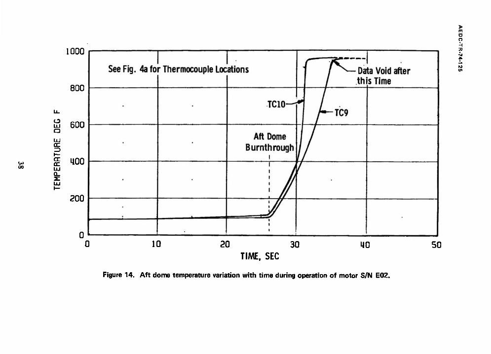
Postfire examination of the motor revealed a large burnthrough in the aft dome approximately 12 in. long and 5 in. wide (Fig. 13). Inspection revealed all propellant to have been consumed. Examination of temperature data for thermocouples located in the area of the failure (TC9 and TC10, Fig. 14) indicated no significant temperature increase prior to the time of the failure.
4.3.2 Motor S/N E01
Postfire examination of the motor revealed a complete case failure at the aft dome (Fig. 15). The aft dome and nozzle assembly was abruptly ejected from the motor at the time of the dome failure. Examination of the linear potentiometer data which measured the relative axial movement between the aft dome and the AEDC mounting adapter (Fig. 16) indicated an axial growth of 0.15 to 0.23 in. at the time of dome failure. As with motor S/N E02, the temperature data obtained from thermocouples located on the aft dome (TC9 and TC10) indicated no significant temperature increase prior to the failure. The exposed aft propellant surface remaining after the failure exhibited numerous depressions (Fig. 15) approximately 2 in. in diameter and 0.1 to 0.5 in. deep.
4.3.3 Motor S/N E11
Motor case and nozzle temperature variations with time are presented in Fig. 17.
The Model Specification (Ref. 5) requires that the maximum case temperature not exceed
12

AEDC-TR-74-126
500°F between motor burnout and 200 sec after motor burnout. The maximum case temperature measured was 408°F, occurring at a position 17.4 in. aft from the forward adapter ring (TC6, Fig. 17c). The maximum measured nozzle temperature was 695°F, occurring 18S sec after ignition at a location 1S.S in. forward of the exit plane (TNI2, Fig. 17g) at an area ratio of 7.
Postfire examination of the motor case and nozzle revealed structural integrity to be satisfactory. No case delaminations or discolorations were observed (Fig. 18).
Erosion of the nozzle during the firing produced a 14.3-percent increase in throat area and a 0.5 -percent increase in exit area from the prefire measurements.
Examination of the circumferential linear potentiometer data (Fig. 19) indicates a relative "twist" between the motor aft thrust ring and AEDC mounting adapter to be about 0.005 to 0.006 in., measured counterclockwise, looking upstream.
4.4 NONAXIAL THRUST VECTOR MEASUREMENT
Measurement of the nonaxial (lateral) component of motor thrust was a primary objective of this test program. The recorded lateral thrust data were corrected for installation and/or electronic effects using the technique described in Ref. 7. The resulting data are presented in Fig. 20.
The maximum magnitude of nonaxial thrust recorded during the near steady-state portion of motor operation is listed below, together with the corresponding angular location and average values:
Motor S/N E02 E01 Ell
Maximum Magnitude of Nonaxial Force, lbf 35 48 11
Angle at which Maximum Force Occurred, deg 190 0 90
Average Magnitude of Nonaxial Force, lbf 22 40 5
L
Remarks Motor failed 27 Motor failed 8 Successful Motor sec after ignition sec after igni- Operation
tion
13

AEDC-TR-74-125
Based on pretest dynamic calibrations, the estimated uncertainty of the nonaxial force measurements during the near-steady state portion of motor S/N El 1 operation is about ±0.7 lbf.
5.0 SUMMARY OF RESULTS
Three Thiokol, Inc., TE-M-640 solid-propellant rocket motors were tested to determine motor altitude ballistic performance and the nonaxial thrust vector and to demonstrate the structural integrity of the motor case and nozzle under the combined effects of rotational spin and simulated altitude conditions while spinning about its axial centerline at 180 rpm. The results are summarized as follows:
1. The first two motors tested (S/N's E02 and E01) resulted in case failures in the aft dome. The third motor tested (S/N Ell), manufactured using a revised process procedure, performed satisfactorily:
a. Motor S/N E02 experienced a burnthrough at the aft dome about 27 sec after ignition. Performance of the motor was normal for about the first 4 sec after ignition, after which the chamber pressure level increased approximately 20 percent higher than predicted, reaching a maximum of 919 psia at 12 sec after ignition. Low-level burning continued for about 13 sec following the failure until the remaining propellant was consumed.
b. Motor S/N E01 experienced a case failure at about 8 sec after ignition, resulting in detachment of the nozzle and aft dome. Abrupt termination of burning occurred, leaving approximately 433 lb of propellant remaining intact in the motor.
2. Postfire examination of motor S/N El 1 revealed the motor case and nozzle structural integrity to be satisfactory.
3. The maximum motor case temperature measured at 200 sec following motor burnout was 408°F for motor S/N El 1, which was below the specification maximum of 500°F.
4. The altitude ballistic performance of motor S/N Ell was within the specification limits:
a. Vacuum total impulse, based on ta, was 173,559 lbf-sec, which was within the specification limits of from 171,600 to 174,020 lbf-sec. Vacuum total impulse based on ts was 173,971 lbf-sec; there were no specified limits on this parameter.
14

AEDC-TR-74-125
b. Vacuum specific impulse, based on total bum time and the manufacturer's stated propellant weight, was 288.94 lbf-sec/lbm.
c. Action time (ta), the time interval between 10 percent of maximum chamber pressure during ignition and 10 percent of maximum chamber pressure during tailoff, was 29.81 sec. This was within the specified limits of from 28.4 to 32.0 sec.
d. Total burn time (t,), the interval between the first indication of chamber pressure during ignition and the time at which the ratio of chamber-to-cell pressure had decreased to 1.3 during tailoff, was 32.92 sec.
5. The maximum magnitude of nonaxial thrust recorded for motor S/N El 1 during the near steady-state portion of motor operation was 11 lbf and occurred 2.S sec after the first indication of chamber pressure. The average magnitude of the nonaxial thrust vector was about 5 lbf.
6. Ignition delay time, the time interval from first indication of chamber pressure until chamber pressure has risen to 90 percent of maximum, ranged from 0.120 to 0.1 SO sec for the three motors tested, which falls within the specified limits of from 0.71 to 0.165 sec.
REFERENCES
1. Test Plan 2360-198. "Qualification Tests for the TE-M-640 Altair III Rocket Motor." El3-73 - Rev. A, Thiokol, Inc., Elkton, Maryland, April 26, 1973.
2. Merryman, H. L. "Performance of a UTC FW-4S Solid-Propellant Rocket Motor under .the Combined Effects of Simulated Altitude and Rotational Spin." AEDC-TR-68-253 (AD844025), November 1968.
3. Interm Report - Altair III Qualification Failure Analysis, Vol. II, Thiokol, Inc., Elkton, Maryland, October 3, 1973.
4. Test Plan - Altair III Confirmation Test at the Arnold Engineering Development Center, LTV/VSD, Dallas, Texas, June 21, 1974.
5. Model Specification No. SC0104C Rocket Motor FW-4S, May 20, 1969.
IS
AEDC-TR-74-125
6. Test Facilities Handbook (Tenth Edition). "Rocket Test Facility." Vol. 2, Arnold Engineering Development Center, May 1974.
7. Nelius, M. A. and Harris, J. E. "Measurements of Nonaxial Forces Produced by Solid-Propellant Rocket Motors Using a Spin Technique." AEDC-TR-65-228 (AD474410), November, 1965.
16
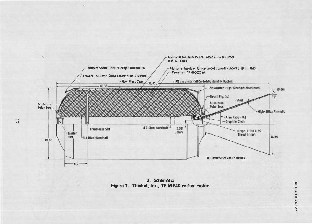
Aluminum Polar Boss
Forward Adapter (High-Strength Aluminum)
ff- Forward Insulator (Silica-Loaded Buna-N Rubber)
r Fiber Glass Case
Additional Insulator (Silica-Loaded Buna-N Rubber) 0.05 in. Thick
Additional Insulator (Silica-Loaded Buna-N Rubber) 0.10 in. Thick PropellantrrP-H-3062»)
Aft Insulator (Silica-Loaded Buna-N Rubber)
All dimensions are in inches.
a. Schematic Figure 1. Thiokol, Inc., TE-M-640 rocket motor.
> m o o
■si

00
o
to
b. Photograph Figure 1. Continued.

Rubber Liner (TL-H-304) (0.025 in. Thick for S/N's E02 and E01 and 0.050 in. Thick for S/N Ell)
Silica-Filled Buna-N Rubber Insulator
Propellant (TP-H-3062)
Filament-Wound Glass Fiber Case (Aft Dome)
Aluminum Aft Polar Boss
Graphite Cloth Phenolic
Carbon Cloth Phenolic Backup -Nozzle Throat Insert (Graph-I-Tite G-90)
c. Detail of nozzle/case interface Figure 1. Concluded.
m O o H 91
W

D o
Pellet Retainer
BKNO3 Pellets
o
9.26 in,
Chamber Pressure Port (Typical of Two)
TP-H-3062M Propellant
Igniter Squib Port (Two Ports - One with Squib* Installed, and One with Pyrogen Pressure Transducer Installed)
*Hercules Powder Company Part Number SD60A-1 Nominal 6-sec Delay Squib
Figure 2. TP-640 pyrogen igniter.

bJ
Load Cells Thrust System Deadweight Calibrator-i
AEDC Mounting Adapter-
Camera fTyp.)
TE-M-640 Rocket Motor
Diffuser r Steam Ejector
Cradle Support Stand
^Thrust Cradle
Flexure All Dimensions in Inches
a. Schematic Figure 3. Installation of TE-M-640 motor and spin assembly in Propulsion Development Test Cell (T-3).
> m D o I H 3D

AEDC-TR-74-125
b. Photograph Figure 3. Concluded.
22

17.4 14.7 1
»•—•« / \
TC4&20 TC5 TC6
TC3 ^^TC16,17,18&19
^-TC2
"-TC1
H*-10.9
TC7 TC8
/TNll TNI 2
All Dimensions in Inches
TN14
a. Thermocouples Figure 4. Instrumentation locations.
> m a o ■H 3D
«J

AEDC-TR-74-125
Circunferentlal Potentiometer (Motor S/N E01 and Ell)
270
Motor Aft Ring
EDC Mounting Ring
View Aft Looking Forward
All Dimensions in Inches
Not to Scale
b. Linear potentiometers Figure 4. Continued.
24

to
7135-73 ;,
c. Photograph of linear potentiometers Figure 4. Concluded.
> m O O
-J

o o
to OS
is
tsuu
,
n A V
6,000
* 4.000
2.000
JO
—l/l—
5.97 6.07 6.17
Time after Application of Ignition Voltage, sec
6.27 6.37
a. Motor S/N E02 Figure 5. Variation of thrust, chamber pressure, and pyrogen pressure during ignition.

600
400
200
0
6.000
£ 4,000
■a 2 2,000
o
1 '
*. - n IM ™ H] uui «.
—^1
kl 1 ■■ ■ II -^ 1
gg
2,400
1.600
800
0 N- 5.83 5.93 6.03
Time after Application of Ignition Voltage, sec
b. Motor S/N E01 Figure 5. Continued.
6.13 6.23 6.33
> m O O A 30 i
<J1

to oo
2500 -
£ 2250-
*" 2000 +
1750- y in tn tf 1500
5 1250 o § 1000 +
750
500-
250-
0-
0_
9000
8000
(n UJ oc a. cc ÜJ oo s: cr x <_>
CO
IOOOT 10000
900--
800-
700 ■ ü, 7000
600-
500
400-
300 ■
200
100- 1000
o-l- 0 0.0
V>
cc I
6000
5000
4000
3000
2000
unaiiiuei ricasu re
Thr JSt
Pyrogen 3ressure
o o
x
fO <J1
0.2 0.4 0.6 0.8 1.0
TIMEAFTER FIRST INDICATION OF CHAMBER PRESSURE, SEC
c. Motor S/N Ell Figure 5. Concluded.

5.0^ 1000- r 10> <103
4.5- CE
900- 9 (T »—* •—> in 4.0- . in
a. 800- 8 CL
• 3.5- - UJ QC
700- ■ u_ GO
7 CC 3 _J
CO 3.0- in ■ in 600- m 6
to UJ t— LÜ oc CO CC Q_ 2.5- a.
oc 500- 3
■ ec 5 _J ÜJ i-
Hi 2.0- . CO 400- 4 o a
X 1.5- . u 300- 3
1.0- 200- 2
0.5- 100- 1
o.o-l oJ 0
-
Chamber Pressure
Thrust-^
r Cell P essure
/ _rV . I—:—J -f 1 0 10 20 30 40 50
TIME AFTER FIRST INDICATION OF CHAMBER PRESSURE, SEC
Figure 6. Variation of thrust, chamber pressure, and test cell pressure during testing of motor S/N E02.
> m O o H a
10

1000
o
CD
CD l_
lO (/) (U 1_ Q- k_ CD
"I CD
O
> m a n
8 12 16 20 24
Time after First Indication of Chamber Pressure, sec
Figure 7. Comparison of actual versus predicted chamber pressure variation with time for TE-M-640 motor S/N E02.

00
5.0-1 1000- r lOxlO3
4.5- cr
900- 9 or »>4
4.0- . <n Q. 800- 8
Q_
• UJ
3.5- ■ UJ cc 700-
CO oc =3 _j
3.0- tfi
- <n 600- ■ *_• 6 tn UJ H- UJ cc tn Q_ 2.5- a.
oc 500- ■3 5
X _l UJ ►-
UJ 2.0- . CO 400- 4 o s
1.5- . u 300- 3
1.0- 200- 2
0.5- 100- 1
o.o-l o-l 0
—i 1 r Thrust "Spike" at Failure
I 1 1— r Pressure
1 Cell Pressure
0 10 20 30 40
TIME AFTER FIRST INDICATION OF CHAMBER PRESSURE, SEC
Figure 8. Variation of thrust and chamber pressure during failure of motor S/N E01.
50
> m O O i -I 3D
N 01

1000
to
.2
CD u. =3 CO
CD
CD -Q
E CD
o O o
■Predicted (Ref. 3) ^ 1
>
8 12 16 20 24
Time after First Indication of Chamber Pressure, sec
28
■V \
^
o o
FO
32
Figure 9. Comparison of actual versus predicted chamber pressure variation with time for TE-M-640 motor S/N E01.

.a
E is .c U
1^—Aft Dome
unn
Am
onn
7m
14,000
12,000
10,000
8.000
6.000
4.000
2,000
0
-2.000
■ ; ■" !
A
A
*i #\ 1 ■ ' ! ■ ' . ■ i • i * • ■■ / V v - ̂ M^^"
7.9 8.0 8.1 8.2 8.3 Time after First Indication of Chamber Pressure, sec
8.4 8.5 8.6
Figure 10. Variation of thrust, chamber pressure, and test cell pressure during failure of motor S/N E01.
> in o o H =0
Ul

•Ft
5.0
4.5
Q_
3.5- UJ 700- fe cc
jo 3.0 + en
a. 2.5
2.0 +
1.5
1.0"
0.5-
0.0-
IOOOT IOXIO3
900 <x £ 800-
oc
10 600 to
500 - oc Cu
oc UJ g 400 cz 5 300
200
100
0 ■
CD
to oc X
8
7
6
5
2
1
0
trfhamber P -essurc
Thrust—'
Test Cell Pressure 5—7 V. -"-Aw
D O
30
0 10 20 30 MO 50
TIME AFTER FIRST INDICATION OF CHAMBER PRESSURE, SEC
a. Variation of thrust, chamber pressure, and test cell pressure during testing of motor S/N E11 Figure 11. Performance of motor S/N Ell.

40
30
m 20
h
X> E at ä 10
1 1 1
Motor S/N Ell
>-<!>{!)-
30 31 32 33 34
Time after Ignition, sec
b. Chamber pressure during tailoff Figure 11. Concluded.
35 36
> m o o
M Ol

AEDC-TR-74-125
*o tfiignition
►I I I *bd t«tailoff *s
"bd
- IF C /
bd
P__,, dt + c. A, K»~ - | F dt + *„ I P„„,, dt + c. A.. | P„h dt vactotal J ex(avg) J cel1 f th(post) ' ch
*o *o *bd
vac action
-bd
- I F dt + A f J eX(avg) J
bd
P__n dt + c. A. ex, x 1 "cell ~" T **£ "th, ^v ) *ch vg) J (post) ' I
"tailoff
P-u dt
aignition a
t2 t2
bd
/ F dt + Aex(post) I pcell dt
/
where: c. *2
Ath(post) J Pch dt
tl
/■
established from data during the time interval from 24.5 to 25.5 sec after first indication of chamber pressure.
Figure 12. Definition of vacuum total and action impulse for motor S/N Ell.
36

-0
Figure 13. Postfire photograph of motor S/N E02.
> m O O •H 3D
01
1*1 oo
UJ Q
cr
1000
800
600
400
200
> m o o
en
0 10 20 30 40 TIME, SEC
Figure 14. Aft dome temperature variation with time during operation of motor S/N E02.
50

Figure 15. Postfire photograph of motor S/N E01.
> m a o
3)

o
, 0.25
0.20
tn ÜJ
5 0.15
z cc •— in •—• a
z 0.10
0.05
0.00
. Time of Aft Dome Failure—v
/~\ "V
/
>^—^-
^ I
^ SeeF ig. 4b for Potentiometer Location
/ ■
/
> m O o I H 3D ■j
M U1
Ü 6
TIME. SEC
8 10
a. Potentiometer LI Figure 16. Axial movement of aft dome relative to motor aft thrust ring for motor S/N E01.

0.25
0.20
tu £ 0.15
E 0.10 tn
0.05
0.00
1 Time of Aft Dome Fa lure~v
/
/
^ / See Fig. 4b for Potentiometer Location
/
6 8 10
TIME. SEC
b. Potentiometer L2 Figure 16. Continued.
> m O o •H as
IS» (II

*. ro
0.25
0.20
en UJ
£ 0.15
g 0.10 I— <n •—• D
0.05
0.00
^-Time of Aft r\nmn Coilurn
SeeF ig. 4b for Potentiometer Location
-
> rn O O I H 30
ro
8 10
TIME. SEC
c. Potentiometer L3 Figure 16. Concluded.

500
400
ü. 300 e
cc
£ 200 cc
100
TC2> =^=i —— -
^ ̂ & -^r —
/ '/,
/* TCl^
// V / ^
s ß*afß^£^
C^
120 240 360
TIME AFTER IGNITION. SEC
480 600
a. Forward dome (TCI, TC2, and TC3) Figure 17. Variation of motor temperature with time for TE-M-640 motor S/N Ell.
> m o o

LU OC
\— (X OC
500
400
300
200
100
See Fig. 4a for Thermocouple Locations
/ 4
^TC2C
<TC4
> m O O '-i
120 2110 360
TIME AFTER IGNITION. SEC
480 600
b. Cylindrical section opposite transverse propellant slot (TC4 and TC20) Figure 17. Continued.

500
400
u_ 300
cc ID
<x cc
200
100
TCoj^
TC5-^ K)^!
MC7
See Fig. 4a for Thermocouple Locations
120 240 360
TIME AFTER IGNITION. SEC
c. Cylindrical section (TC5, TC6, TC7, and TC8) Figure 17. Continued.
480 600
> m O o i H X
Ul

UJ az I— d cc LU Q_
ÜJ
500
400
300
200
100
TC9^_
TCIO^
SeeF g. 4a for Thermocouple Locations
m O o H 31
■A IO U1
120 240 360
TIME AFTER IGNITION. SEC
d. Aft dome (TC9 and TC10) Figure 17. Continued.
480 600

500
U00
u_ 300
CC CC LU Q-
200
100
TC15-X
See Fig. 4a for Thermocouple Location
r
120 240 360
TIME AFTER IGNITION. SEC
e. Pyrogen case (TC15) Figure 17. Continued.
U80 600
> m o o 3>
to

OO
500
400
o o
u. 300
E 200
0_
100
TC16-T
TC18-L
TC17J
TC19^
See Fig. 4a for Thermocouple Locations
-
120 240 360
TIME AFTER IGNITION. SEC
480 600
f. Forward dome (TC16, TC17, TC18, and TC19) Figure 17. Continued.

LU CC
<X CC LU Q_ s: LU
700
560
1120
280
mo
^TN12 TN11-L
TN13-7"
WN14
See Fig. 4a for Thermocouple Locations
120 240 360
TIME AFTER IGNITION. SEC
g. Nozzle (TN11, TN12, TN13, and TN14) Figure 17. Concluded.
M80 600
> m O o H 31
10

O
o o ■H 3) ■il A
M
A E D C 5994-74
Figure 18. Postfire photograph of motor S/N Ell.

0.010
l/>
c 0) u • Q> s
g
b c •H CD o e v v > > o
■HS +J CO iH 0) ta
0.008
0.004
See Fig. 4b for Potentiometer location. Positive movement denotes counterclockwise rotation. Aft looking forward.
5 10 15 20 25
Time after First Indication of Chamber Pressure, sec
30
Figure 19. Relative circumferential movement between aft thrust ring and AEDC mounting adapter during motor operation (S/N E11).
> m o o I -\ 9
tf!

AEDC-TR-74-125
g
8000
7000
6000
5000
4000
3000
2000
1000
n
Near Steady-State Thrust
1 >
> 5
2 3 rE 1
f te 240
> 1 I 160
X
I 0 4 8 1 2 1 6 2 0 2 4 ?!
Time after First Indication of Chamber Pressure, sec
a. Motor S/N E02 Figure 20. Variation of nonaxial (lateral) force vector with
time during motor operation.
52

AEDC-TR-74-125
7000
<000
1 , /
2 5000 f
^ 4000 i 3000
2000
1000
48
40 i—
M _ & 24 •35 § 2 16
S1 <
0
240
160
15 S"
2 5
320,
y
4^ 8 12 16 20 24 28 Time after First Indication of Chamber Pressure, sec
b. Motor S/N E01 Figure 20. Continued.
53

AEDC-TR-74-125
I/) 3
10x10
■G S 20
Oi —~
> «D b
rust
itu
d
10 r tz \— Jg»
"re *£ 5 L. OJ
3 0
.. i_ 360 to ro ö* = "5 -g
240 -< g 2 oi 120 .2 o O n a> Q. -i >
\" —S XT >-^- -= !•■«*•
^4^/^^ 0 5 10 15 20 25 30 Time after First Indication of Chamber Pressure, sec
c. Motor S/N E11 Figure 20. Concluded.
54

Table 1. Instrument Summary and Measurement Uncertainty
Parameter Designation
STEADY-STATE ESTIMATED MEASUREMENT*
Bange
Precision Index (S)
Bias <B>
Uncertainty ±<B ♦ tgsS)
Type of Measuring Device
Type of Recording Device
MetSod of Systea Calibration
a a o wtJ vi
i Oh* «!■ a 2* I!
'S ■ S 5 U *H V
VI ml
at Si
9 n a «4 E o ■
Axial Force, lbl to.08 — 123 10.03 — 10.19 — 3000 to 70O0 lbf Bonded Strain-
Gags-Type Force Transducers
Sequential Sampling, Mllllvolt-to-Digltal Converter, and Mag-
In-Place Application of Deadweights Cali- brated in the Standards Laboratory Total Impulse,
lbf-see 10.07 — 31 10.03 — ±0.17 — netic Tape Storage Data Acquisition Systea
f
Chamber Pressure, pmla ±0.09 — 41 10.07 — 10.25 — 300 to
900 paia
Bonded Strain- Gage-Type Pres- sure Transducers
Resistance Shunt Based on the standards Lab- oratory Dateralnatlon of Transducer Applied Pressure versuB Resis- tance Shunt Equivalent Pressure Relationship
f
Chamber Pressure, Integral, psia-sec 10.08 — 31 10.07 — 10.23 —
f Low-Bange Climber Pressure, pala
±0.3 — 31
10.5 — 11 Rote 1 — 0.5 to
15 psia
10.1 — 10.2 — ±0.4 Note 2
— 15 to 50 pala
Test Cell Pressure, psla 10.2 — 39 ia.0 — 12.4 — 0.05
to 0.B pala Unbonded Straln-
Oage-Type Pres- sure Transducers Teat Cell Pressure
Integral, pala-aec to.a — 31 12.0 — 12.4 —
Relative Tangential Movement, in.
10.002 in. 31 — 10.001
in. 10.005
in. 10.05
in. Rectilinear Potentiometer
In-Place Application of
ftM«!.^!S!n5ck' Standards Laboratory
Weight, lbm 10.015 lbm 31 — 10.06
lbm 10.1
lbm
B00 to 1500 lba
Bean-Balance Scales
Visual Readout
In-Place Application of Deadweights Calibrated in the Standards Lab- oratory
Caaa Temperaturo/F 10.25'F 100 — 12.2'F 12.7'F 70 to 450'F
Chroael-Alumel Tenpsrature Transducers
Sequential Saspllng, Ililllvolt-to-Dlgltal Converter, and Mag- netic Tape Storage Data
Millivolt Substitution Based on the NBS Tem- perature versus mill- volt Tables
Nozzle Teap, "F 10.25*? 100 — 12.2*F 12.7*F 70 to
530*F
1(0.25% + O.B'F) 1(0.25% * 1.4*F) 530 to 700"F
'REFERENCE: CPIA No. 180. "ICRPG Handbook for Estimating the Uncertainty In Measurements made with Liquid Propellent Rocket Engine Systems." (AD855130), April 30, 1969.
NOTES: 1. 16-psia full-scale transducer. 2. 50-psla full-scale transducer.
> m o o 3)
01

> m o o i H X
Ol
Table 1. Concluded
OS
Parameter Designation
STEADY-STATE ESTIMATED MEASUREMENT*
Range Type of- Mensuring Device
Method of Syoten Calibration
Precision Index (S)
Bias (B)
Uncertainty ±(B + t95S)
Type of Recording Device « m
a a e «4 u *. -ü h O ■ & &
1 ■H O
SSI si R R e *i Eos e e o, «
I -X. 0 0 fa ♦*
3 O +* m C •H « a Rj
n a ft «i u *. V U 0 *
£ £
i «4 V 0 u +*
9 a 4* a o ■H a I
£1
pyrogen Pressure, psia " 10.1 — 31 ♦0.2 10.4 —
500 to 2000 psla
Bonded Strain- Gage-Type Pressure Transducers
Sequential Sampling, Mllllvolt-to-Dlgital Converter, and Magnetic Tape Storage
In-Place Application of Deadweights Cali- brated In the Standards Laboratory
nozzle Strain pin./in. 10.5 — 31 id. no,
Mote 3 —
1000 to 12,000 uln./lnj Strain Grid
Data Acquisition System
f
Resistance Shunt Based -on the Manufacturer's Determination of Elongation versus Resistance ChanRe
Lateral Thrust Vector Magnitude, lbf
10.25 lbf 31 10.2
lbf .... 10.7
lbf
1.5 to 12 lbf
Bonded Strain- Gage-Type Force Transducers
In-Place Application of Multiple Force Levels Measured with Force Transducers In the Standards Laboratory
DOTES: 3. Uncertainty Estimates Based on Experience with Systems Similar to those Furnished by User.

AEDC-TR-74-125
Table 2. Summary of TE-M-640 Motor Performance
Test Number R41C-04A (RA307)
Motor Serial Number
Test Date
Average Motor Case Temperature at Ignition, *F
Ignition Lag Time (tj)1, sec
Ignition Delay Time (t<j)2
Action Time (ta)3, sec
Time of Nozzle flow Breakdown (t^)*
Total Burn Time5, time interval that nozzle throat flow was sonic (ts), sec
Simulated Altitude at Ignition, ft
Average Simulated Altitude during ta> ft
Maximum Vacuum Thrust, lbf
Maximum Chamber Pressure, psia
Measured Total Impulse (based on t^d). lbf-sec Average of Four Channels of Data Maximum Channel Deviation from Average,
percent
Chamber Pressure Integral (based on t^l, psia-sec Average of Two Channels of Data Maximum Channel Deviation from Average,
percent
Cell Pressure Integral (based on tp<j). psia-aec Average of Two Channels of Data Maximum Channel Deviation from Average,
percent
Chamber Pressure Integral, psia-sec from tfcd to t8
Vacuum Total Impulse (based on ta), lbf-sec
Vacuum Total Impulse (based on t8), lbf-sec
Vacuum Specific Impulse (based on ta), lbf-sec/lbm - Based on Manufacturer's Stated Propellant
Weight Baaed on Expended Mass (AEDC)
Vacuum Specific Impulse (based on t8), lbf-sec/lbm Based on Manufacturer's Stated Propellant
Weight Based on Expended Mass (AEDC)
Average Vacuum Thrust Coefficient, Cp Based on ta and Average Pre- and Fostfire
Throat Areas
Maximum Case Temperature, *F
Specification Limits6
01 02 03
E02 E01 Ell
7/11/73 8/30/73 7/12/74
83 85 76
5.97 5.91 5.72
0.150 0.137 0.120 0. 071 to 0.165
* ** 29.81 28.4 to 32.0 * *» 29.58
* ** 32.92
119,000 122.000 123,000 * 44 105.000
7529 7295 6889
919 909 832
* »4 172,372
- - 0.01
4 ** 20,640
- - 0.06
* 44 3.890
- - 0.11
* ** 86.9 * ** 173. 559 171.600 to 174.020 * *4 173,971
4 4
»* 44
2B8.26 286.54
• *
44 44
288. 94 287.22
* 44 1.834 4 «* 408 <500*F (at 200 sec from
motor burnout)
Defined as the time interval from application of ignition voltage (t0) to the first perceptible rise in chamber pressure (tj).
"Defined as the time interval from the first indication of chamber pressure until chamber pressure has risen to 90 percent of maximum.
^Defined as the time interval beginning when chamber pressure increases to 10 percent of maximum chamber pressure at ignition and ending when chamber pressure has fallen to 10 percent of maximum chamber pressure during talloff.
^Defined as the time after ignition where exhaust diffuser flow breakdown occurs, as indicated by an abrupt increase in cell pressure during talloff.
5Defined as the time interval between the first indication of chamber pressure at ignition and the time at which the ratio of chamber-to-cell pressure has decreased to 1.3 during tailoff.
6Model Specification No. SC0104C, May 20, 1969. Docket Motor FW-4S. »Motor case failure occurred 27 sec after Ignition.
*4Motor case failure occurred 8 sec after ignition.
57

00
> m O
Table 3. Summary of TE-M-640 Motor Physical Dimensions 9 H 3)
1
M 01
Test Number 01 02 03
Motor Serial Number E-02 E-01 E-ll
Test Date 7/11/73 8/30/73 7/12/74
AEDC Prefire Motor Weight1, lbm 1419.37 1403.27 1486.66
AEDC Postfire Motor Weight1, lbm 806.04* 1233.27** 880.95
AEDC Expended Mass, lbm 613.33* 170.00** 605.71
Manufacturer's Stated Propellant Weight, lbm 601.9 603.7 602.1
Nozzle Throat Area, In.2
Prefire Postfire Percent Change from Prefire
4.272 4.721 +10.51
4.267 ** **
4.271 4.883 +14.3
Nozzle Exit Area, in. * Prefire Postfire Percent Change from Prefire
215.02 215.50 +0.2
215.85 ** **
215.21 216.26 +0.5
Prefire Nozzle Area Ratio 50.33 50.59 50.39
1Weight Includes 822.1 lbm for AEDC Firing Harness, Pressure Transducers, Instrumentation, etc.
*Motor case burnthrough resulted in loss of case material. #*Motor case failure resulted in loss of nozzle assembly and aft dome.