unclassified - defense technical information center · ftc-produced by national technical...
TRANSCRIPT
AD-782 202
A COMPUTER PROGRAM FOR THREE- DIMENSIONAL LIFTING BODIES IN SUBCONIC INVISCID FLOW
F. A. Woodward, et al
Flow Research, Incorporated
Prepared for:
Army Air Mobility Research and Development Laboratory
April 1974
DISTRIBUTED BY:
KUn National Technical Information Service U. S. DEPARTMENT OF COMMERCE 5285 Port Royal Road, Springfield Va. 22151
1
Unclassi f ier i SECURITY CLASSIFICATION OF THIS PAGE flWi.n D . f . e„,.,.d)
REPORT DOCUMENTATION PAGE READ INSTRUCTIONS BEFORE COMPLETING FORM
R E P O R T N U M B E R 2 . G O V T A C C E S S I O N N O
USAAMRDL-TR-74-18 3. R E C I P I E N T ' S C A T A L O G N U M B E R
^ / ) ^ « . T I T L E (mrtd Subtitle)
A COMPUTER PROGRAM FOR THREE-DIMENSIONAL LIFTING BODIES IN SUBSONIC INVISCID FLOW
5. T Y P E O F R E P O R T A P E P I O O C O V E R E D
F i n a l Repor t
« . T I T L E (mrtd Subtitle)
A COMPUTER PROGRAM FOR THREE-DIMENSIONAL LIFTING BODIES IN SUBSONIC INVISCID FLOW 6 P E R F O R M I N G O R G . R E P O R T N U M B E R
Flow Research Report 26
F. A. Woodward F. A. Dvorak E. K. G e l l e r
8 . C O N T R A C T O R G R A N T N U M B E R f a )
C o n t r a c t DAAJ02-73-C-0065
9 . P E R F O R M I N G O R G A N I Z A T I O N N A M E A N D A D D R E S S
Flow Research, I n c . Ken t , Washington 98031
10 P R O G R A M E L E M E N T . P R O J E C T . T A S K A R E A A W O R K U N I T N U M B E R S
Task 1F162204AA4102 ' 1 . C O N T R O L L I N G O F F I C E N A M E A N D A D D R E S S
E u s t i s D i r e c t o r a t e U. S. Army A i r M o b i l i t y R&D L a b o r a t o r y F o r t E u s t i s . V i r g i n i a 23604
12. R E P O R T D A T E
A p r i l 1974
' 1 . C O N T R O L L I N G O F F I C E N A M E A N D A D D R E S S
E u s t i s D i r e c t o r a t e U. S. Army A i r M o b i l i t y R&D L a b o r a t o r y F o r t E u s t i s . V i r g i n i a 23604
13. N U M B E R O F P A G E S
Ml l « . M O N I T O R I N G A G E N C Y N A M E » A O O R E S S f / / dlllerartt from Controlling Otllce) 15. S E C U R I T Y C L A S S , rot thla report)
U n c l a s s i f i e d
l « . M O N I T O R I N G A G E N C Y N A M E » A O O R E S S f / / dlllerartt from Controlling Otllce)
15a D E C L A S S I F I C A T I O N / D O W N G R A D I N G S C H E D U L E
i©. U l b 1 H l d U 1 I O N S T A T E M E N T (ol thla Report)
Approved f o r p u b l i c r e l e a s e ; d i s t r i b u t i o n u n l i m i t e d .
' 7 . D I S T R I B U T I O N S T A T E M E N T (ol the abstract entered In Block 20. If different from Report)
18. S U P P L E M E N T A R Y N O T E S —
ftc-produced by NATIONAL TECHNICAL INFORMATION SERVICE U S Department of Commerce
19. K E Y W O R D S (Continue on reverae aide It neceaaary and Identity by block number)
Three d i m e n s i o n a l Sources Bodies Ang le o f a t t a c k S e p a r a t i o n Yaw-Fuselages V o r t i c e s
2 0 . A B S T R A C T (Continue on rmvaraa aide It nacaaaary and Identity by block number)
A computer program f o r the a n a l y s i s o f w ing -body comb ina t i ons i n subson i c f l o w i s d e s c r i b e d . The c o n f i g u r a t i o n i s r e p r e s e n t e d by a l a r g e number o f s u r f a c e p a n e l s , cach c o n t a i n i n g a c o n s t a n t source d i s t r i b u t i o n . The c i r -c u l a t i o n about l i f t i n g s u r f a c e s i s p r o v i d e d by a system o f v o r t e x l a t t i c e s l o c a t e d on the mean camber s u r f a c e . The s t r e n g t h s o f the sources and v o r t i c e s wh ich s a t i s f y t h e boundary c o n d i t i o n o f t a n g e n t i a l f l o w f o r a g i v e n Mach number, ang le o f a t t a c k , a n d / o r ang le o f yaw a re de te rm ined by
1473 EDITION OF 1 MOV 65 IS OBSOLETE Unclassified
SECURITY CLASSIFICATION OF THIS PAGE fW»«n Data Entered)
L J
llnclassifieU SECURITY CLASSIFICATION OF THIS PAGEfWun Dmtm Bnlmrmd)
block 20
solving a system of linear equations by an iterative procedure.
The program computes the pressure coefficients at the panel centroids and integrates these pressures numerically to obtain the lift, drag, and pitching moments of the configuration.
Unclassified
ri SECURITY CLASSIFICATION OF THIS PAüCflTh«! OaM Entmfd)
-■^j ' i In „tiairtiMiMlilMttiagiiltlii
r
PREFACE
This program was sponsored by the Eustis Directorate, U. S. Army Air Mobility Research and Development Laboratory, and was monitored by Mr. James Gillespie. This program was authorized by Contract DAAJO2-73-C-0065, DA Task 1F162204AA4102.
iii
TABLE OF CONTENTS Page
PREFACE m
LIST OF ILLUSTRATIONS vi
INTRODUCTION 1
AERODYNAMIC THEORY 2
Description of Method 2 The Incompressible Velocity Components 4 Compressibility Corrections 8 The Boundary Condition Equations 9 Calculation of the Pressures, Forces, and Moments 14 Separated Flow Model 17
COMPUTER PROGRAM ... 24
Program Description 24 Program Structure 24 Program Input Data 24 Program Output 41 Program Time Estimation 41 Program Usage 41 A General Guide to Paneling Wing-Body Nacelle Configurations 49
COMPARISON WITH EXPERIMENT 52
CONCLUSIONS 69
REFERENCES 70
APPENDIXES
I. Panel Geometry Calculations 71
I.I. Subroutine Descriptions 77
III. Sample Input 106
IV. Sample Output 110
LIST OF SYMBOLS I37
Preceding page blank V
LIST OF ILLUSTRATIONS
Figure Page
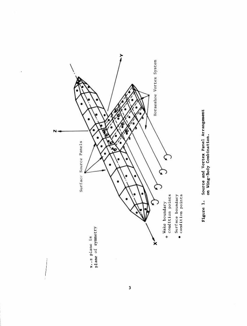
1 Source and Vortex Panel Arrangement on Wing-Body Combination 3
2 Source Panel Geometry 4
3 Line Vortex Geometry 6
4 Vortex Lattice 7
5 Modeling of Potential Flow to Account for Boundary Layer and Wake 18
6 The BO 105 Helicopter Fuselage Showing Paneling and Separation Modeling 20
7 Pressure Distribution Along Top Centetline of the BO 105 . 21
8 Pressure Distribution Along Waterllne 10 of the BO 105 . . 22
9 Program Overlay Structure 25
10 CPU Time Required for CDC 6600 42
11 Body Cross Section 43
12 Wing Section 44
13 Wing Vortex Lattice 46
14 Vortex Lattice Inside Body 47
15 Vortices in Vertical Tail 48
16 Panel Representation for BO 105 Helicopter Configuration 53
17 Pressure Distribution for BO 105 along Fuselage Top o o
Centerline a = 0 , 6 = 0 56
18 Pressure Distribution for BO 105 along Fuselage Water line 10
a = 0° , ß = 0° 57
VI
Figure Page
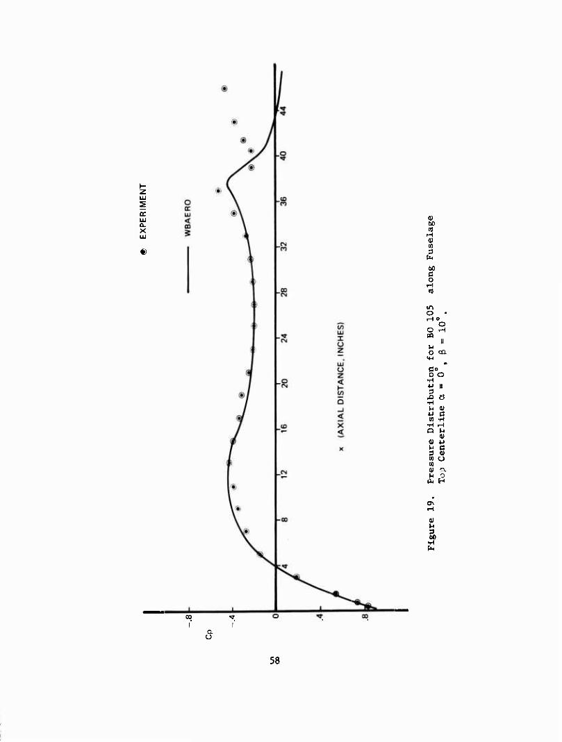
19 Pressure Distribution for BO 105 along Fuselage Top o o
Centerline a = 0 , ß =10 58
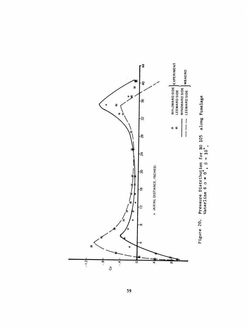
20 Pressure Distribution for BO 105 along Fuselage 0 0
Waterline 6 a = 0 , ß =10 59
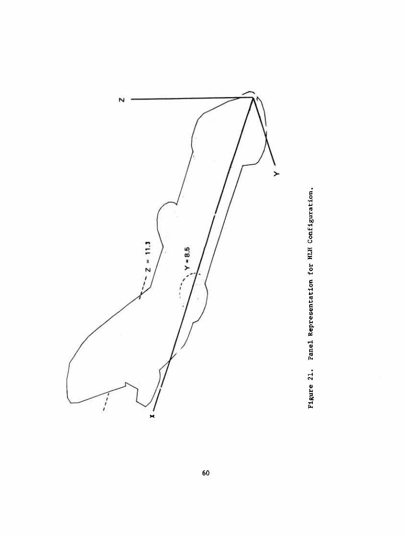
21 Panel Representation for HLH Configuration 60
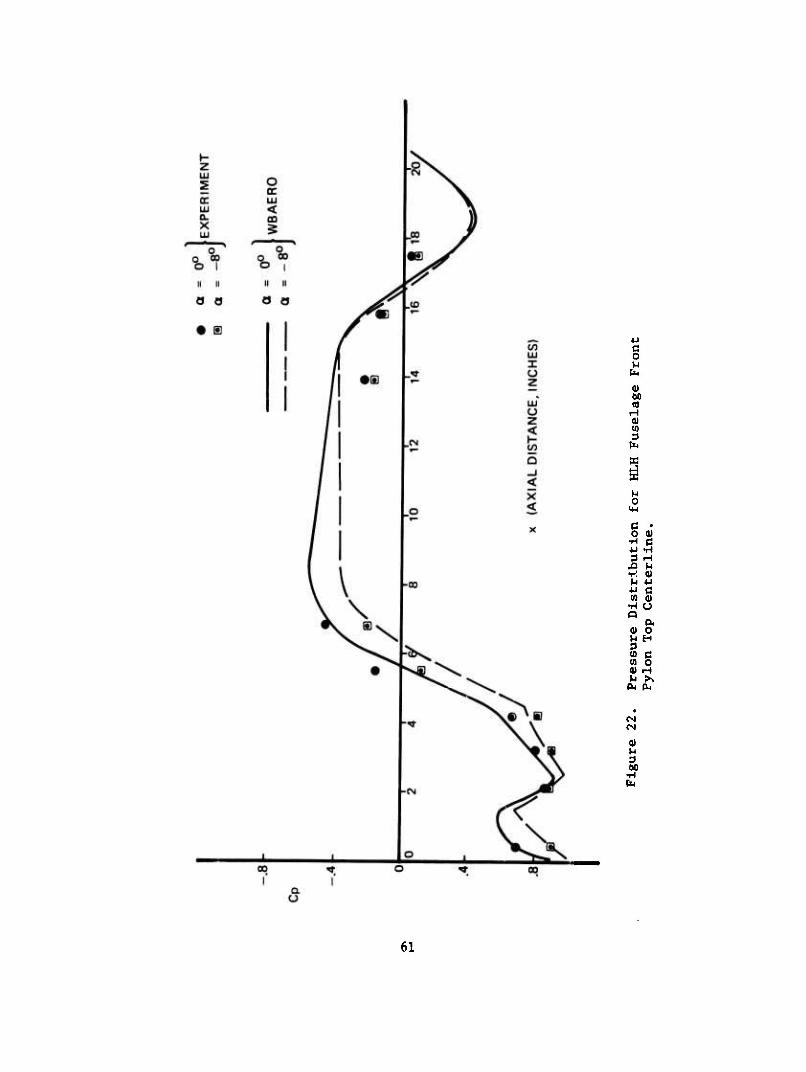
22 Pressure Distribution for HLH Fuselage Front Pylon Top Centerline 61
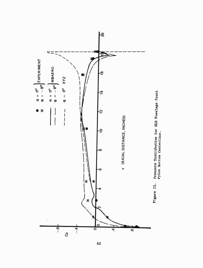
23 Pressure Distribution for HLH Fuselage Front Pylon Bottom Centerline 62
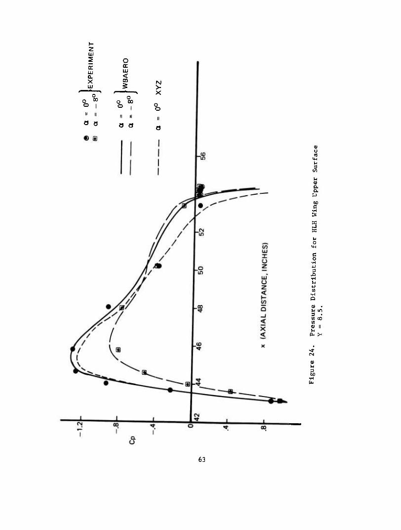
24 Pressure Distribution for HLH Wing Upper Surface Y = 8.5 63
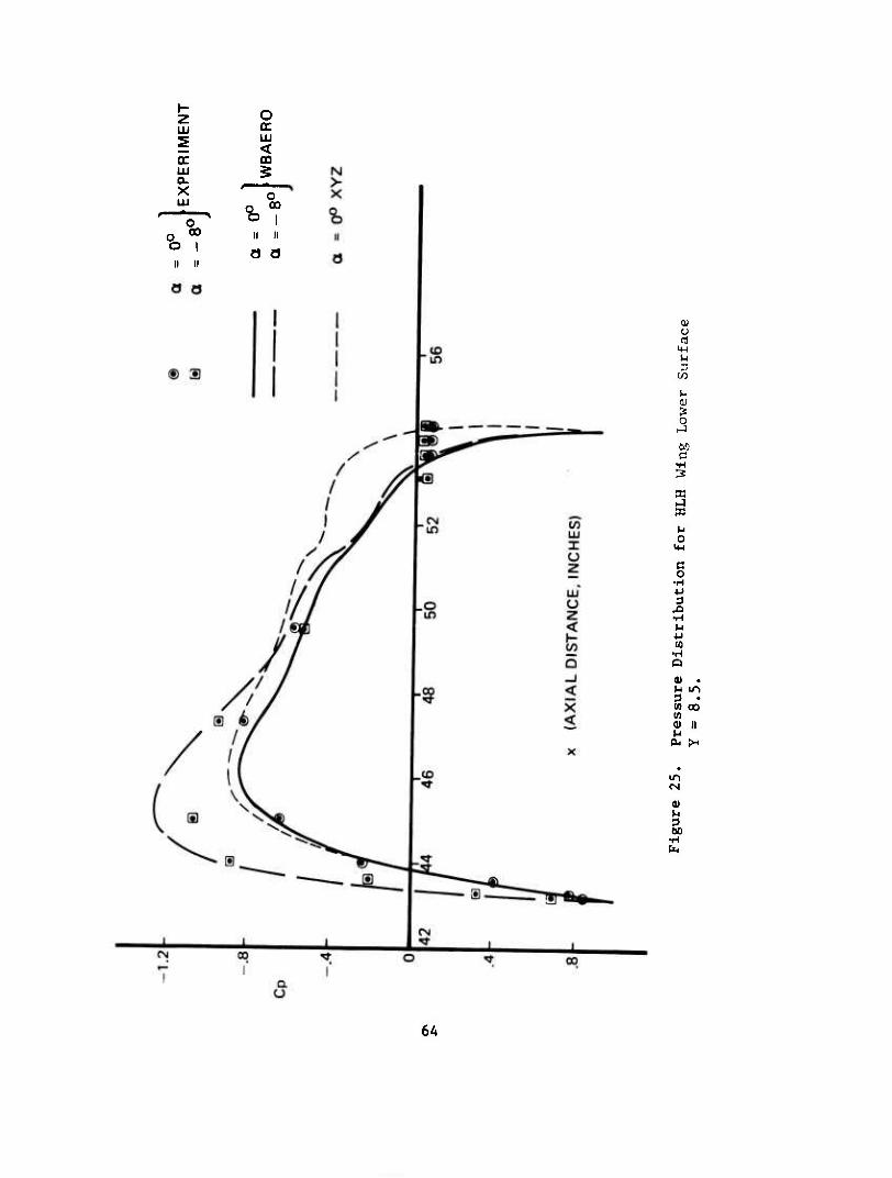
25 Pressure Distribution for HLH Wing Lower Surface Y = 8.5 V,
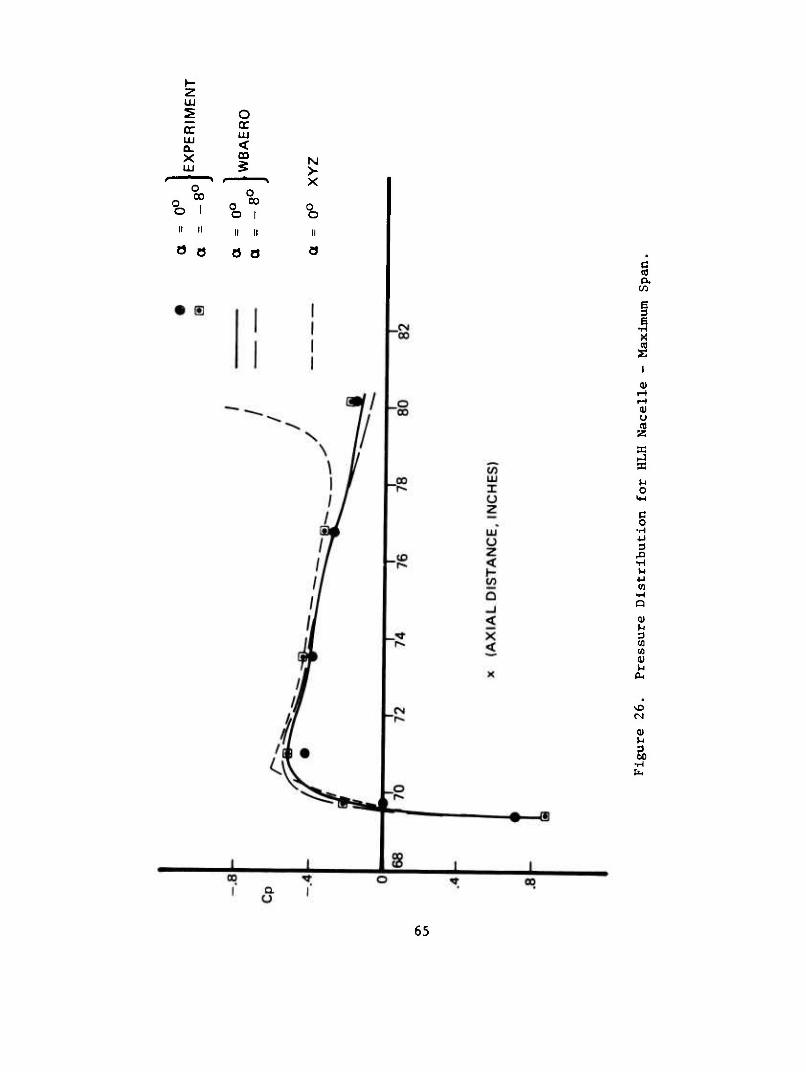
26 Pressure Distribution for HLH Nacelle - Maximum Span . . 65
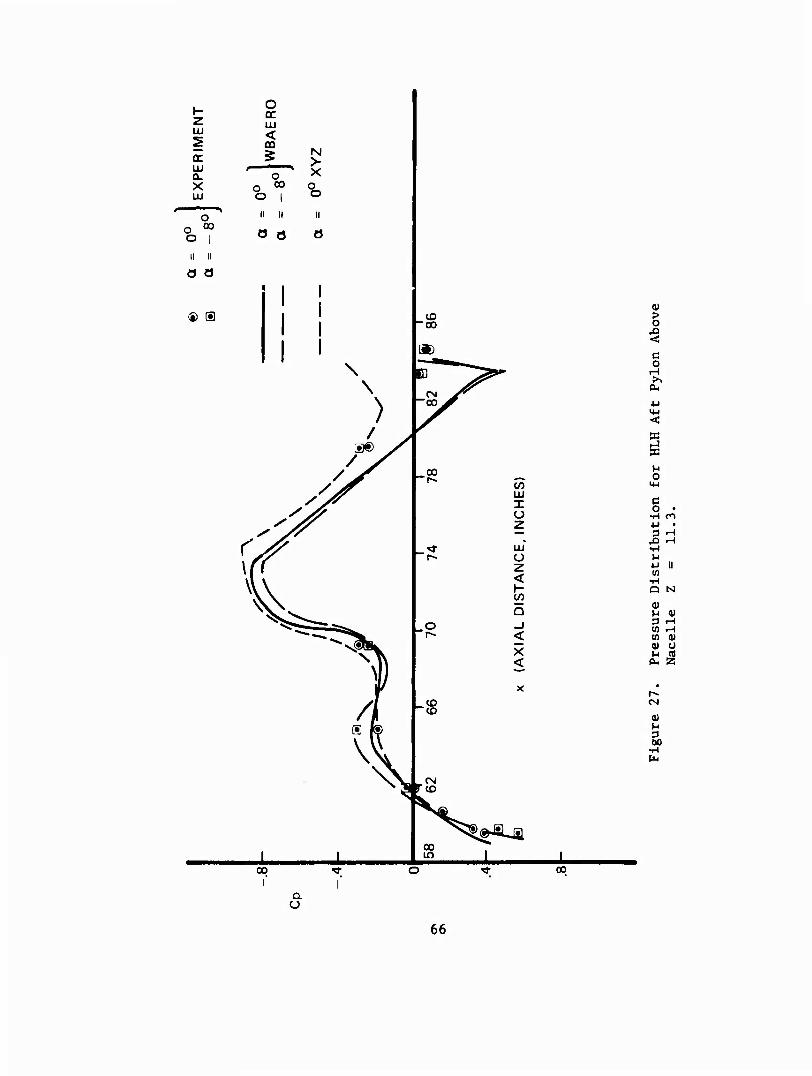
27 Pressure Distribution for HLH Aft Pylon Above Nacelle Z - 11.3 66
28 Panel Representation for Wing-Body-Vertical Tail Combination 67
29 Pressure Distribution on a Low Aspect Ratio Vertical Tail 68
vii
• larirMiiiiiiiriii»!
INTRODUCTION
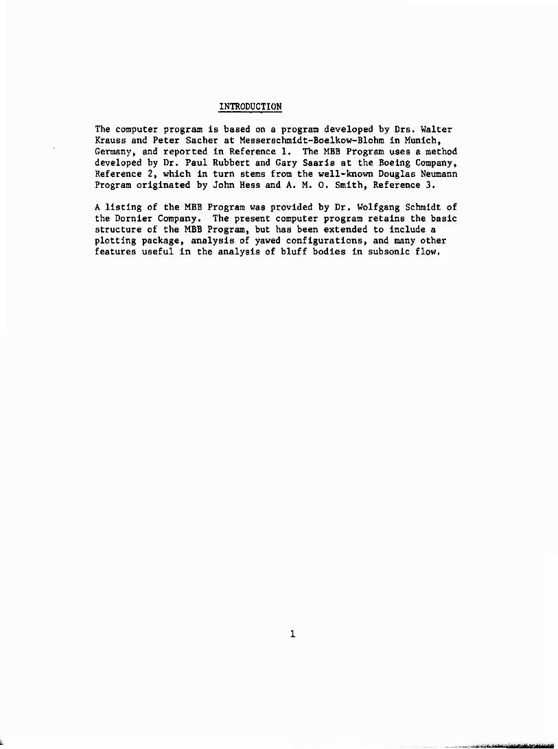
The computer program Is based on a program developed by Drs. Walter Krauss and Peter Sacher at Messerschmidt-Boelkow-Blohm in Munich, Germany, and reported in Reference 1. The MBB Program uses a method developed by Dr. Paul Rubbert and Gary Saaris at the Boeing Company, Reference 2, which in turn stems from the well-known Douglas Neumann Program originated by John Hess and A. M. 0. Smith, Reference 3.
A listing of the MBB Program was provided by Dr. Wolfgang Schmidt of the Dornier Company. The present computer program retains the basic structure of the MBB Program, but has been extended to include a plotting package, analysis of yawed configurations, and many other features useful in the analysis of bluff bodies in subsonic flow.
- MÜ --■■■-'"
AERODYNAMIC THEORY
DESCRIPTION OF METHOD
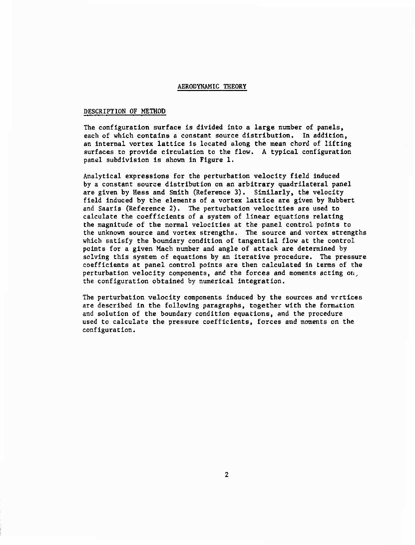
The configuration surface is divided Into a large number of panels, each of which contains a constant source distribution. In addition, an internal vortex lattice is located along the mean chord of lifting surfaces to provide circulation to the flow. A typical configuration panel subdivision is shown in Figure 1.
Analytical expressions for the perturbation velocity field induced by a constant source distribution on an arbitrary quadrilateral panel are given by Hess and Smith (Reference 3). Similarly, the velocity field induced by the elements of a vortex lattice are given by Rubbert and Saaris (Reference 2). The perturbation velocities are used to calculate the coefficients of a system of linear equations relating the magnitude of the normal velocities at the panel control points to the unknown source and vortex strengths. The source and vortex strengths which satisfy the boundary condition of tangential flow at the control points for a given Mach number and angle of attack are determined by solving this system of equations by an iterative procedure. The pressure coefficients at panel control points are then calculated in terms of the perturbation velocity components, and the forces and moments acting on^ the configuration obtained by numerical integration.
The perturbation velocity components induced by the sources and vertices are described in the following paragraphs, together with the formation and solution of the boundary condition equations, and the procedure used to calculate the pressure coefficients, forces and moments on the configuration.
N
M >, M ■u u 4J C CO C
>■, •H -a •H u 0 c 0 cd D. 3 a
XI 0 c C .O c 3 o 0 0 •H ffl •H
J3 4-1 o 4-1 •H ra •H
OJ ■a tu ■o ^i e u c ID 0 3 0 3 u w u
g 60
u
*«• iH O
C 4J (0 CD
04 C
4J u o >
1 0) u
o
u >>
I (3 o
(U
I (X4
THE INCOMPRESSIBLE VELOCITY COMPONENTS
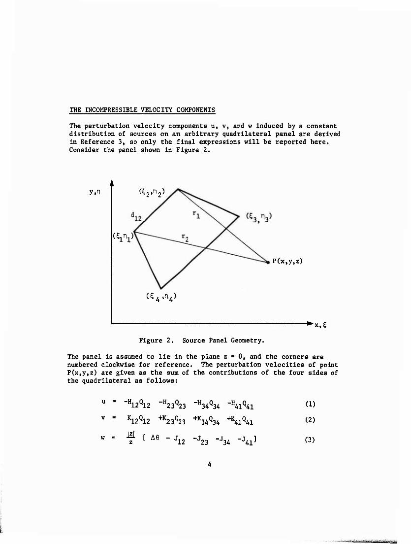
The perturbation velocity components u, v, and w induced by a constant distribution of sources on an arbitrary quadrilateral panel are derived in Reference 3, so only the final expressions will be reported here. Consider the panel shown in Figure 2.
y.n (?2.n2)
(W
(VV
P(x,y,z)
^x.C
Figure 2. Source Panel Geometry.
The panel is assumed to lie in the plane z *■ 0, and the corners are numbered clockwise for reference. The perturbation velocities of point P(x,y,z) are given as the sum of the contributions of the four sides of the quadrilateral as follows:
w
-H12Q12 -H23Q23 -H34Q3A -H^Q^
K12Q12 +K23Q23 +K34Q34 +K41Q41
f [ Ae - J12 -J23 -J34 -J4i]
(1)
(2)
(3)
where
K 1J
H ij
'U
'Ij
ij
lib. dij
Vni ij
log
'ij
tan 'i^^-^i^) (x-q) H - (y - n ^ K
ij
'ij - (^ - x) K^ + (n1 - y) H ij
rij " {h -x) Kij + (r)3 - y> H.J
2^2,1/2 [(x -q) '+ (y -r^) ^]
[ii ' [Ui"?j) + (Vnj) ] 2,1/2
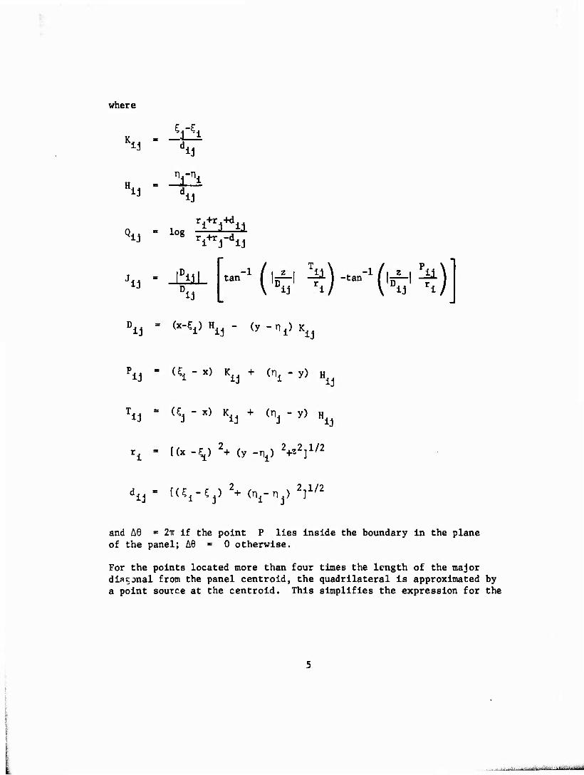
and A9 " 2Tr if the point P lies inside the boundary in the plane of the panel; AS ■ 0 otherwise.
For the points located more than four times the length of the major diagonal from the panel centroid, the quadrilateral is approximated by a point source at the centroid. This simplifies the expression for the
. .„ - ^—»
velocity components considerably.
In this case,
-3 u - (x - x) S/r
v - (y - y) S/r -3
w = (z - z) S/r -3
(4)
(5)
(6)
where
r = [(x - x)2 + (y - y)2 + (z - i)2] 1,2
S = panel area
and x, y, z are the coordinates of the panel centrold.
Additional multlpole expansion formulas for the velocity components given in Reference 3 are not used in this program.
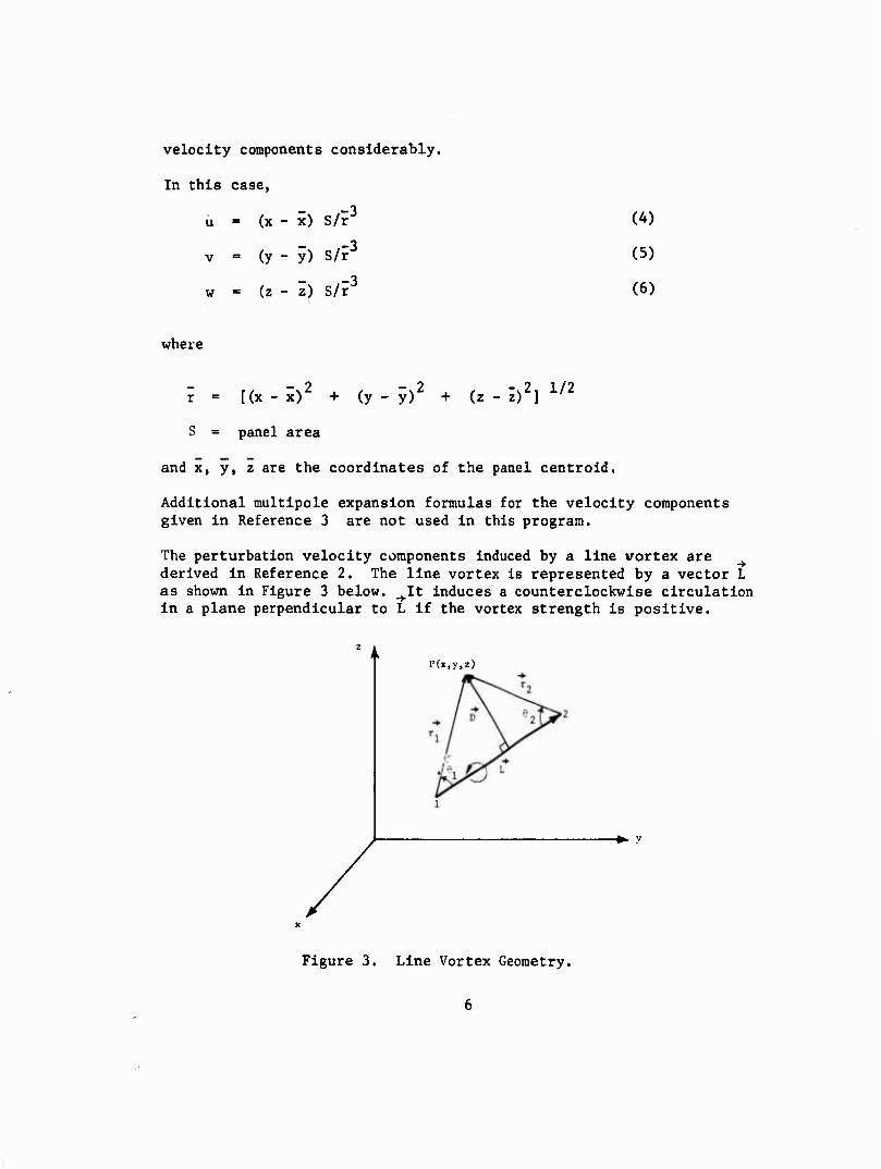
The perturbation velocity components Induced by a line vortex are derived In Reference 2. The line vortex is represented by a vector L as shown in Figure 3 below. ^It induces a counterclockwise circulation In a plane perpendicular to L if the vortex strength is positive.
P(x,y,z)
-♦- y
Figure 3. Line Vortex Geometry.
The velocity at P(x, y, z,) is perpendicular to the plane containing -♦■
L and the point 1, and is given by Biot-Savart s Law as
V = I. r ^^t sin 6 Aa vi TT / "^-rr —2— d8 ,' |DXL| D
Y L 1 4TT (üX T^l
(cosö, - cos 6,, ) (7)
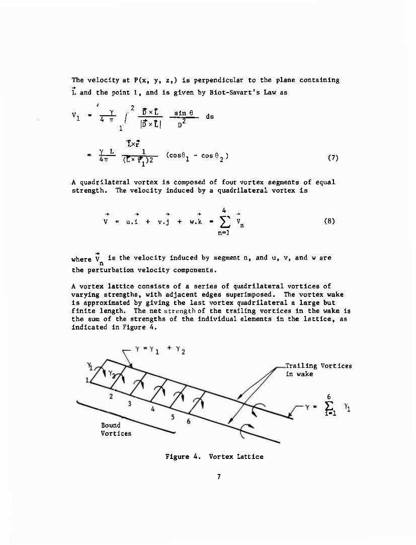
A quadrilateral vortex is composed of four vortex segments of equal strength. The velocity induced by a quadrilateral vortex is
4
u.l + v.j + w.k - J^ Vn
n=]
(8)
where V is the velocity Induced by segment n, and u, v, and w are n
the perturbation velocity components.
A vortex lattice consists of a series of quadrilateral vortices of varying strengths, with adjacent edges superimposed. The vortex wake is approximated by giving the last vortex quadrilateral a large but finite length. The net strength of the trailing vortices in the wake is the sum of the strengths of the individual elements in the lattice, as indicated In Figure A.
Bound Vortices
Trailing Vortices in wake
&
Figure 4. Vortex Lattice
The relative strengths of the Individual bound vortices in the lattice are specified in advance. The circulation around each airfoil section is determined by the net strength of each vortex lattice.
COMPRESSIBILITY CORRECTIONS
The velocity components in compressible flow are found by applying Gothert's Rule (Reference 4). Two options are available in the program for applying the compressibility corrections, and are designated Rule 1 and Rule 2.
Rule 1 applies the method originally proposed by Gothert. The incompressible velocity components are calculated on an analogous
body obtained by the following transformation:
(9)
where
X a
X
^a S By
za = Bz
B f~H2
The boundary conditions of tangential flow are applied on the analogous body, and the resulting incompressible perturbation velocities are trans- formed back to the real body by
u - u / B a
v = v / B (10) n
w = w / B a
The total velocity vector at a given point is then
U ■ U^ cos a cos 6 + u
V » U^ sin B + v (11)
W = U sin a cos ß + w 00
It is now known that this compressibility rule yields good results only for slender bodies at small angles of attack. The validity of this rule decreases with increasing values of the surface slope. This
effect is particularly noticeable for two-dimensional airfoil sections. In the vicinity of the nose, Gothert's Rule (which is equivalent to the Prandtl-Glauert Rule in this example) gives excessively high suction peaks on the upper surface. The reason for this failure of the theory is the manner in which the boundary conditions are satisfied. Since the boundary conditions are satisfied at the surface of the analogous body which is thinner by the factor B than the real bod>, the curvature of the flow near the nose is correspondingly Increased, resulting in higher suction peaks. In order to eliminate this effect, it is necessary to satisfy the boundary conditions on the surface of the real body.
Rule 2 was first proposed by Kraus in Reference 1. Beginning with the analog body as before, the expressions for the perturbation velocity components are corrected for compressibility, using Equation 10, prior to solving the boundary condition equations. The boundary conditions of tangential flow are then applied on the surface of the real body, resulting in improved results for the velocities and pressure coefficients.
THE BOUNDARY CONDITION EQUATIONS
The boundary condition of tangential flow at panel control points establishes a system of linear equations for determining the strengths of the source and vortex distributions. The geometrical relationship between each panel and control point is required to evaluate the coefficients of this system of equations.
Panel Geometry
A typical panel subdivision of a wing-body configuration is Illustrated in Figure 1. A reference coordinate system is established with origin at or near the nose of the configuration, having an x-axis lying in the plane of symmetry parallel to the body axis, and a vertical z axis. Symmetry of the body about the x, z plane is not required. However, if the body is symmetric, only those panels located on the positive y side of the x, z plane are required.
The body panel corners are defined by the intersections of a series of planes normal to the x axis, and longitudinal meridian lines. A maximum of 70 body sections may be used, and each section may contain up to 60 points around the half-circumference. The body panel corner points may be shifted longitudinally to aid in panelirg wing-body intersections. The body panels are numbered in sequence from the top to the bottom of each circumferential ring, starting from the most forward ring.
The wing panels are defined by the Intersections of a series of vertical planes parallel to the plane of symmetry, and lines of constant percent chord. A maximum of 40 wing sections may be defined, each containing up to 60 airfoil ordinates. The same number of ordlnates are required on the upper and lower surfaces of the airfoil, at approximately the same percent chord locations, in order to properly define the internal vortex panels.
The wing panel corner points may be shifted laterally to aid in paneling wing-body intersections. The wing panels are numbered sequentially, and follow the body panels. Beginning with the inner chordwise strip of panels, the numbering starts at the trailing edge of the lower surface, and ends at the trailing edge of the upper surface. A maximum of 1500 panels may be used to define the external surfaces of the wing and body. It the configuration is symmetric, this implies a maximum of 750 panels on one side of the x, ?. plane.
Vortex lattice panels are automatically defined on the mean chord plane of the wing. The panel corner points are obtained by averaging the upper and lower surface airfoil ordinates at each percent chord location. One additional vortex panel is defined in the wake aft of the trailing edge of each chordwise strip of wing panels to provide control points for satisfying the Kutta condition. The additional panel lies in the plane of the trailing edge bisector. For wing-body combinations, additional vortex lattices are required inside the body to provide a mechanism for carry-over of lift. A maximum of 35 vortex lattices may be defined, and these are numbered subsequently following the wing panels.
The four input points defining a panel do not necessarily lie in the same plane. The technique used to approximate the panel by an equiva- lent planar panel was developed by Hess and Smith, Reference 5, and is summarized in Appendix I. Using this method, a panel coordinate system is defined with origin at the panel centroid and lying in the mean plane of the input points. The x axis of the panel coordinate system is parallel to one diagonal, the z axis is normal to the plane of the panel, and the y axis is perpendicular to the other two. Since the velocity components induced by the source distributions are given in terms of the panel coordinate system, a nine element transformation matrix Tij is calculated for each panel to transform the coordinates of points and the components of vectors from the reference coordinate system to the panel coordinate system. In addition, the panel area, the coordinates of the centroid, and the length of the principal diagonal are calculated.
10
Normal Velocity at Panel Control Points
Each surface panel is assigned a control point located at the panel centroid. Each vortex lattice is assigned a control point just behind the trailing edge of the wing in the plane of the trailing edge bisector. (This point is normally located 1 percent of the local chord behind the trailing edge.)
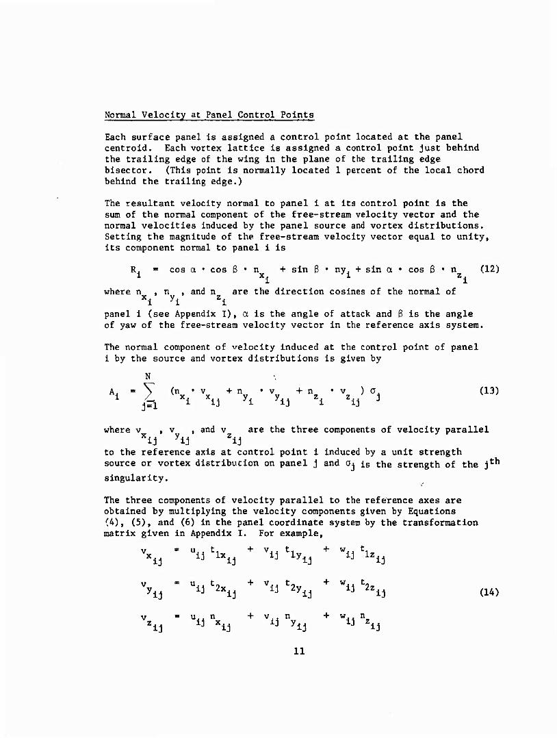
The resultant velocity normal to panel i at its control point is the sum of the normal component of the free-stream velocity vector and the normal velocities Induced by the panel source and vortex distributions. Setting the magnitude of the free-stream velocity vector equal to unity, its component normal to panel 1 is
R. ■ cos a • cos ß • n + sin ß • ny, + sin a • cos ß • n (12) 1 x1 1 z1
where n , n , and n are the direction cosines of the normal of Xl yi Zi
panel 1 (see Appendix T), a is the angle of attack and ß is the angle of yaw of the free-stream velocity vector in the reference axis system.
The normal component of velocity Induced at the control point of panel i by the source and vortex distributions is given by
i, » \ (n'v +n 'v +n 'v )a. (13) 1 /L xi x y1 y44 zA z,/ J
where v , v , and v are the three components of velocity parallel Xlj yij Zij
to the reference axis at control point 1 induced by a unit strength source or vortex distribucion on panel j and a« is the strength of the j*-^1
singularity.
The three components of velocity parallel to the reference axes are obtained by multiplying the velocity components given by Equations (^)» (5), and (6) in the panel coordinate system by the transformation matrix given in Appendix I. For example,
Xi as "u Xj + v« ^1,
+ "u '1^
% s "« S; + -n %
^
s
"« Xj + v . n ij ylj
+ "u "^
(14)
11
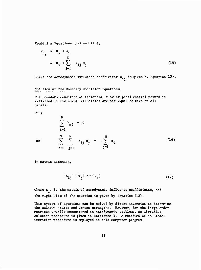
Combining Equations (12) and (13),
V = R. + A, n. i 1
N
" Ri+?J aiiai (15)
J-l
where the aerodynamic influence coefficient a., is given by Equation(13) .
Solution of the Boundary Condition Equations
The boundary condition of tangential flow at panel control points is satisfied if the normal velocities are set equal to zero on all panels.
Thus
or
N
V v , =o
1=1
N N
1 1 ^.l 'i ' i-1 j-l
(16)
In matrix notation.
[A^] io^-i^) (17)
where A.. is the matrix of aerodynamic influence coefficients, and
the right side of the equation is given by Equation (12).
This system of equations can be solved by direct inversion to determine the unknown source and vortex strengths. However, for the large order matrices usually encountered in aerodynamic problems, an iterative solution procedure is given in Reference 3. A modified Gauss-Sledel iteration procedure is employed in this computer program.
12
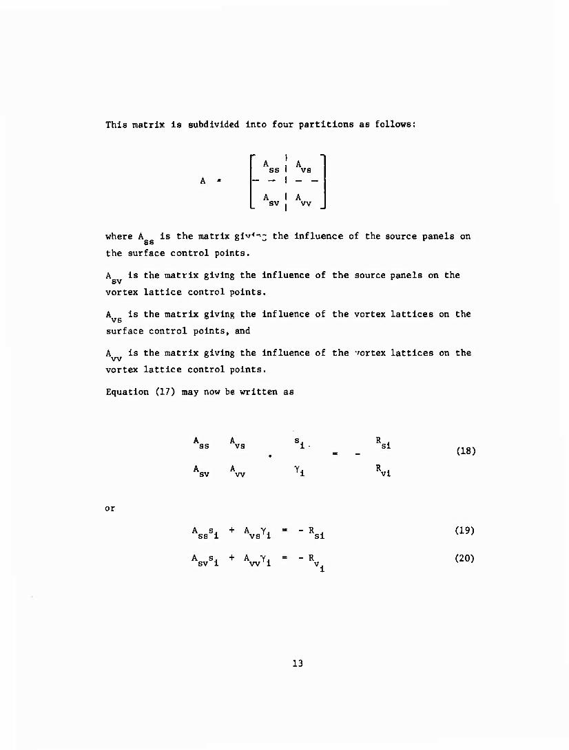
This matrix is subdivided into four partitions as follows:
ss
sv
vs
vv
where A is the matrix glv-'-'; the influence of the source panels on ss
the surface control points.
A is the matrix giving the Influence of the source panels on the
vortex lattice control points.
A is the matrix giving the influence of the vortex lattices on the vs o o
surface control points, and
A is the matrix giving the influence of the vortex lattices on the
vortex lattice control points.
Equation (17) may now be written as
A A ss vs si
(18)
A A sv w vi
or
A s. + A Y.I ss 1 vs i R si
A s. + A YJ = - R sv 1 w 1 v.
(19)
(20)
13
where s. are the unknown source strengt!.3, and y. are the unknown
vortex strengths, A Is a square matrix of order NS, and A is
a square matrix of order NL, where NL is generally much smaller than NS.
The first step in each of the iteration cycles is to use Equation (19) only. The values for y, are taken from the previous cycle (or
set equal to zero on the first cycle) and a solution for the array {s,} is obtained by the Gauss-Seidel procedure. These values for s. are then used in Equation (20) to obtain Y., hy direct inversion:
= -A -1
w
NS
j~i sv
ij (21)
These values are now used in the first step of the next cycle, and the procedure continues until convergence is achieved. The criterion for convergence is
ss ij
S1 ^ J ^
j=l VS1J YJ
< e (22)
where e is some small number specified by the user. Normally e < 10
More elaborate iteration schemes using smaller partitions of the A SS
matrix are ( ?scribed in Reference 6, but have not been incorporated into the present program.
CALCULATION OF THE PRESSURES. FORCES. AND MOMENTS
Once the source and vortex strengths have been determined, the three components of velocity at control point i may be obtained.
-3
N
cos a cos ß + y
J = l N
Hj
sin ß + Y
j=l 'ij
(23)
(24)
14
w. = sin a cos ß + > v 0, 1 -^ Z44 J i^i zij
(25)
where the 0. Includes both source and vortex strengths, and v , j Xij
v , and v are defined following Equation (13). The pressure ylj Zij
coefficient is calculated using the exaft isentropic formula
3.5
KM 2 1 + J£Z1 M
2 (i-q2) - 1 (26)
where 2 2 2,2 q1 = u1 + vi + wi
For M < .1, the program uses the simpler formula
CP1 = 1 - ^i (27)
The forces and moments acting on the configuration can now be obtained by numerical integration. The normal force, side force, axial force, and pitching moments (about the origin of coordinates) of panel 1 are given by
\
M
Si CP nx 1 fi xi
Si CP ny
S. C-, n 1 Pi zi
Vi " Vi
\' Vi - Vi
rM
Zl" Vi - Vi
(28)
(29)
(30)
(31)
(32)
(33)
15
where S. is the area of the panel, n , n , and n are the direction Xi yi yi
cosines of the normal, and x., y, and z. are the coordinates of the
panel control point.
The total force and moment coefficients are obtained by summing the panel forces and moments on both sides of the plane of symmetry
(34)
N
cz -4" W
i=l
N
W i=l
N
w 1\ i=l N
c - ' y M_
t^.
(35)
(36)
"2 Sc ri Zi ^ w i=l
N
7 SwC i-1
N
* V 1-1
Finally, the lift, side force,and drag coefficients are
C, - Czcos a - (C cosß - C sinB) sin a (40)
Cs - CYco8 6 + Cxsin ß (41)
CD * (cxcos ^ ~ CY8in^ cos a + C7slna (42)
16
The program computes the forces and moments acting on the body and the wing, and sums them to obtain the total forces and moments of the configuration. In addition, wing section forces and moments may be calculated at the user's option.
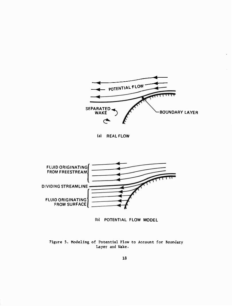
SEPARATED FLOW MODEL
The flow external to the boundary layer and the separated wake Is essentially potential flow. To obtain a mathematical model with potential flow everywhere, the boundary layer and separated wake In the real case are replaced by fluid originating from the body surface as shown In Figure 5. Rules for the distribution of surface normal velocity to account for boundary layer growth upstream of separation have been formulated, and their use requires matching the boundary layer and the potential flow solution by Iteration. Rules for distributing surface normal velocity In the separated region to obtain fluid which will displace the potential flow originating from upstream In the same way as the separated wake In the real case have not been formulated. However, for very unstreamllned bodies, a plaus- ible approach Is to make the surface normal velocity equal to the free- stream velocity component normal to the surface:
V • n = V^ • n (43)
-►
V - surface velocity
->• V^ = free-stream velocity
n = unit surface normal
To calculate the location of separation requires a matching of the boundary layer and potential flow solutions similar to that used for the boundary layer growth, a formldlble Job. However, for an aft body shape with rapid closure or for bodies having sharp corners, making an intuitive estimate of the separation point is consistent with the use of Equation 43.
17
POTENTIAL f LOW
SEPARATED,- WAKE J BOUNDARY LAYER
(a) REAL FLOW
FLUID ORIGINATING FROM FREESTREAM
DIVIDING STREAMLINE
FLUID ORIGINATING FROM SURFACE
(b) POTENTIAL FLOW MODEL
Figure 5. Modeling of Potential Flow to Account for Boundary Layer and Wake.
18
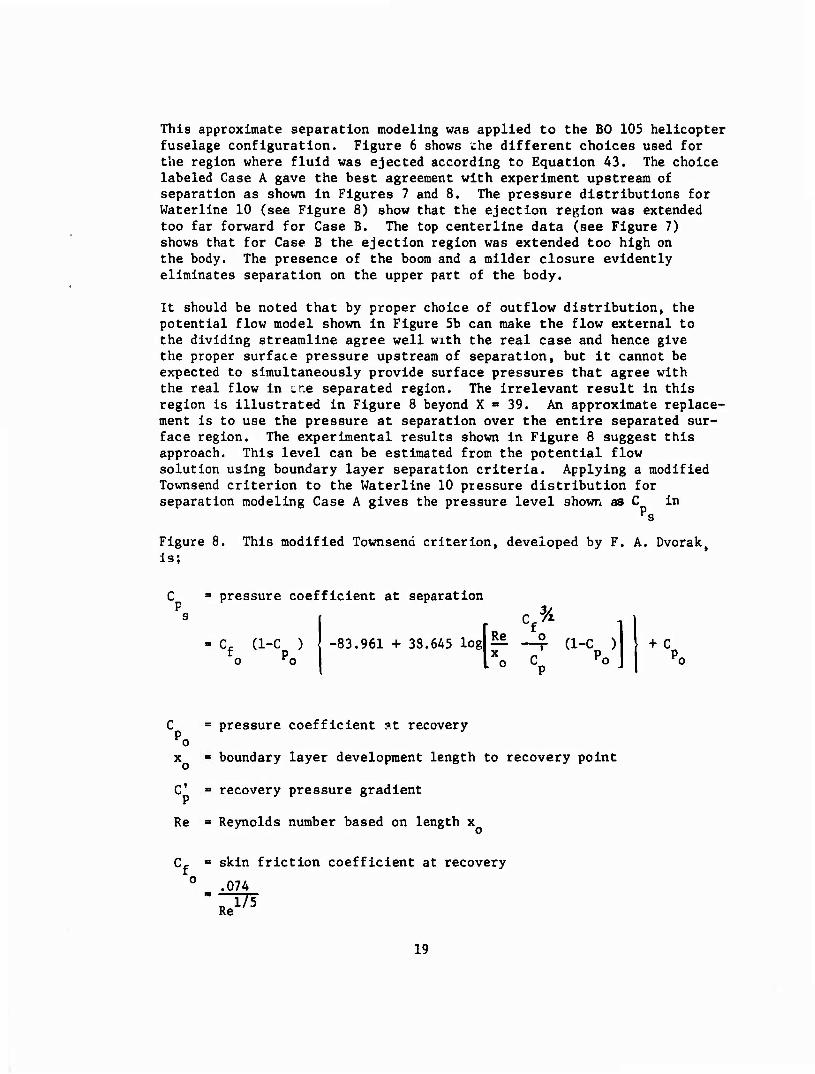
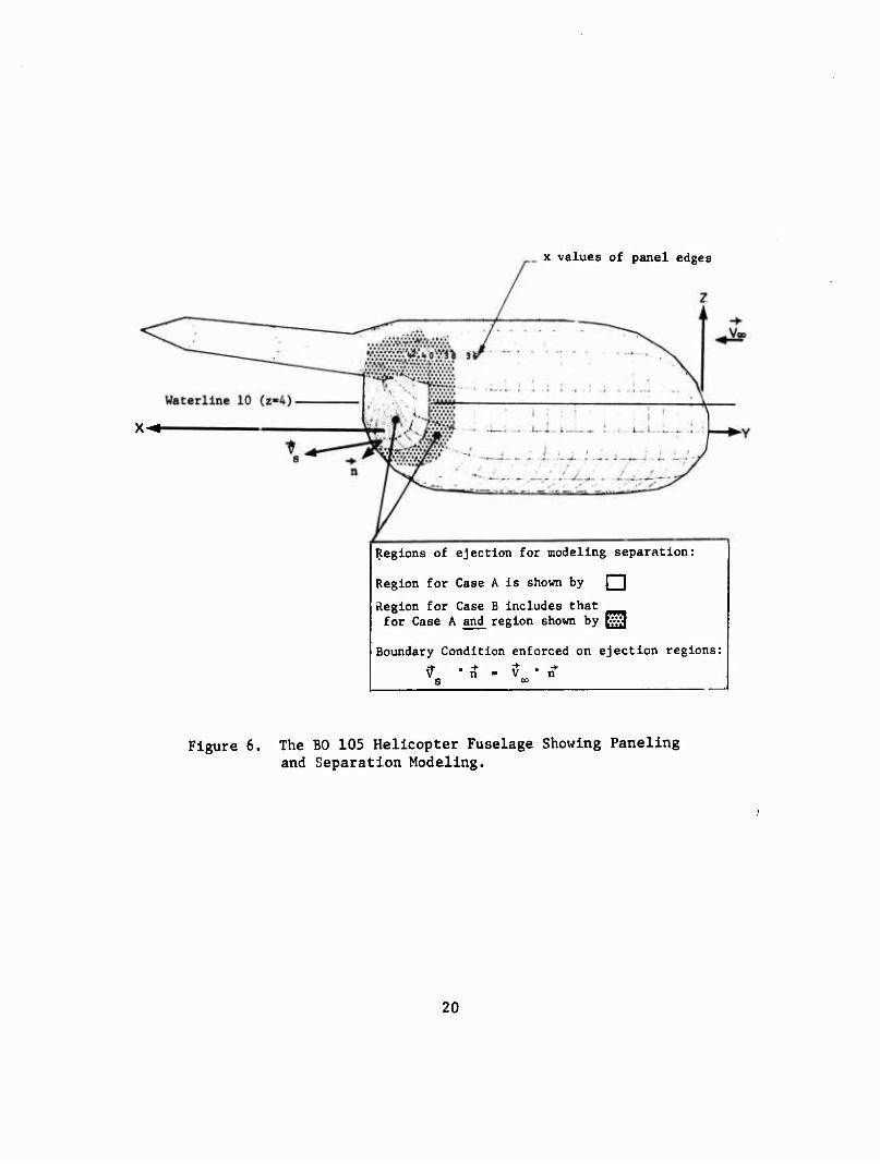
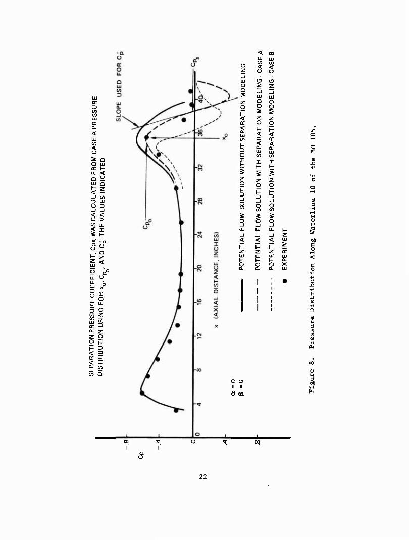
This approximate separation modeling was applied to the BO 105 helicopter fuselage configuration. Figure 6 shows ehe different choices used for the region where fluid was ejected according to Equation A3. The choice labeled Case A gave the best agreement with experiment upstream of separation as shown in Figures 7 and 8. The pressure distributions for Waterline 10 (see Figure 8) show that the ejection region was extended too far forward for Case B. The top centerline data (see Figure 7) shows that for Case B the ejection region was extended too high on the body. The presence of the boom and a milder closure evidently eliminates separation on the upper part of the body.
It should be noted that by proper choice of outflow distribution, the potential flow model shown in Figure 5b can make the flow external to the dividing streamline agree well with the real case and hence give the proper surface pressure upstream of separation, but it cannot be expected to simultaneously provide surface pressures that agree with the real flow in tne separated region. The Irrelevant result in this region Is illustrated in Figure 8 beyond X = 39. An approximate replace- ment is to use the pressure at separation over the entire separated sur- face region. The experimental results shown in Figure 8 suggest this approach. This level can be estimated from the potential flow solution using boundary layer separation criteria. Applying a modified Townsend criterion to the Waterllne 10 pressure distribution for separation modeling Case A gives the pressure level shown as C in
Ps
Figure 8. This modified Townsend criterion, developed by F. A. Dvorak, Is;
C " pressure coefficient at separation
s
- Cf (1-C ) o ro
cf% -83.961 + 38.645 log| ^ —7- (1-C ) IM I 0 cp
+ C p.
C ■ pressure coefficient at recovery o
x ■ boundary layer development length to recovery point
C' = recovery pressure gradient
Re = Reynolds number based on length x
o Cf = skin friction coefficient at recovery
.074
19
x values of panel edges
x-^.
Regions of ejection for modeling separation:
Region for Case A is shown by Q^
Region for Case B includes that for Case A and region shown by tv>3
Boundary Condition enforced on ejection regions:
\r • ft - V • n^
Figure 6. The BO 105 Helicopter Fuselage Showing Paneling and Separation Modeling.
20
o
o M
41
o
e
u 0) 4J
§ u a o H
00
§
c o •H
3 •H
(0 i4 O
(U M
CO (0 0)
Hi
u 3 00
a o
21
er ■D in in LU oc Q.
< LU w < o 5 Q O LU er K u. < Q U LU Q 1- H < -J <n 3 LU O D _l _l < < o > m LU < I 5 H trt - Q. Q. o Q
H Z 2 < LU
u äC
U. o U. LU 0
O o oc LU o u. 3 iD w z 00 LU in OC D Q. 2 z O o 1-
1- 3
< m oc oc < \- Q. co to Q
< m LU LU w in o < < z o o
-J 1 ■
ai ü ü O z z O _J _l
LU tu z o Q o o O H 5 s < z z oc o g < 1- t- 0. LU < < C/3 oc oc 1- 3 2
lU < CL LU
O CA) to X I I
1- h- ? 5 § Z o z z
o o 1- 1- D D _i -J
^ O V5
o 5 g § O o O _i _J _l LL. u. u. 1- _l _i _l z < < < LU s K K H Z Z Z oc LU LU LU LU 1- 1- H CL o O O X ü. 0. a. LU
o o II II
9 oa
o
o
ü
0 o
c
0)
00 c o
c o
3 JD •H H w w
•H Q
0) M 3 03 CO a> dt
oo
3 üO
•H P4
00 l"
a O
00
22
The values for C , C, and x that were taken from the Case A pressure P P o ro r
distribution to calculate C are indicated in Figure 8. The boundary ^s
layer development length x was approximated by using the axial dis- tance from the nose of the body to the recovery point. For the recovery pressure gradient C', the maximum gradient in the recovery region was used.
For the cases shown in Figures 7 and 8, experimental results are avail- able to determine the best ejection configuration for the paneling used, namely, Case A. An obvious problem is that in the absence of experi- mental data, it is not known where to start the surface ejection. It may be possible to determine this point by an iterative procedure using a boundary layer separation criterion. The idea is to start the surface ejection at the separation point calculated from the preceding cycle, an initial guess being used for the first cycle. The example in Figures 7 and 8 shows that for a jump start, ejection must begin some distance downstream from the calculated separation point. Clearly, the iterative procedure suggested requires a gradual initiation of ejection, and the shape used for this initiating "ramp" is critical for convergence and for obtaining an accurate modeling of separation as pictured in Figure 5. Also denser paneling than shown in Figure 6 is necessary to provide more resolution for the ejection distribution.
23
COMPUTER PROGRAM
PROGRAM DESCRIPTION
The program developed to calculate the pressure distribution and aerodynamic characteristics of wing-body combinations in subsonic flow is written in FORTRAN IV, A maximum of 1500 source panels and 35 vortex lattices may be used to represent the configuration. It is designed to operate on both the CDC 6600 or IBM 360/370 series of computer with minor modifications. The program requires approximately 210,000 (octal) words storage on the CDC computer, and operates in OVERLAY mode. The program requires five peripheral disc files in addition to the input and output files.
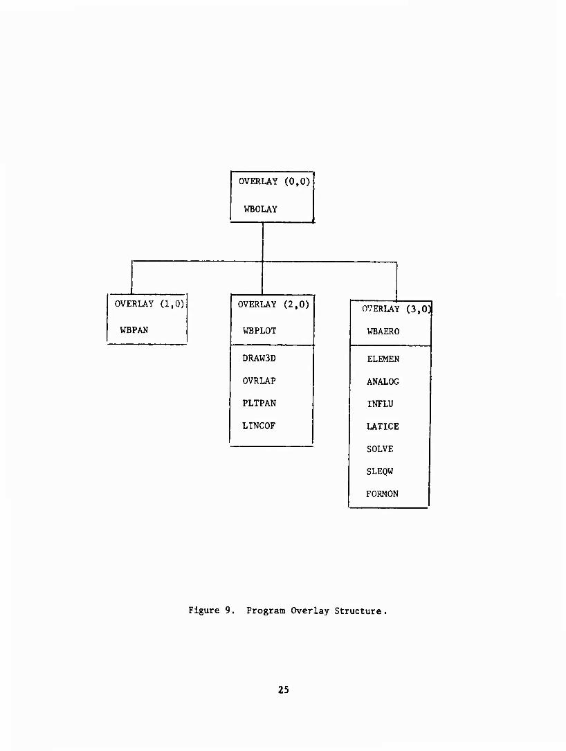
PROGRAM STRUCTURE
The overlay structure of the program Is illustrated in Figure 9. The main overlay program is designated WBOLAY, and calls the three primary overlay programs WBPAN, WBPLOT, änd V7BAE0R. The complete program consists of 16 subroutines in addition to standard library and plot subroutines. Descriptions of these subroutines are contained in Appendix II of this report.
PROGRAM INPUT DATA
The input to the program is divided into three parts: the geometry input, the plot input, and the aerodynamic input. The input require- ments of each part are described below. A sample input is given in Appendix III, and a sample output in Appendix IV.
2A
OVERLAY (0,0)
WBOl .AY
OVE RLAY (1,0) OVERI ̂AY (2,0) OVERLAY (3,0)
WBPAN WBPLOT WBAERO
DRAW3D ELEMEN
OVRLAP ANALOG
PLTPAN INFLU
LINCOF LATICE
SOLVE
SLEQW
FORMON
Figure 9. Program Overlay Structure.
25
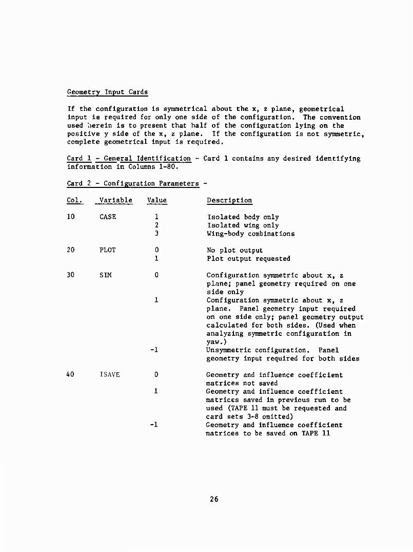
Geometry Input Cards
If the configuration Is symmetrical about the x, z plane, geometrical Input is required for only one side of the configuration. The convention used herein Is to present that half of the configuration lying on the positive y side of the x, z plane. If the configuration Is not symmetric, complete geometrical Input is required.
Card 1 - General Identification - Card 1 contains any desired identifying information in Columns 1-80.
Card 2 - Configuration Parameters -
Col.
10
Variable
CASE
Value
1 2 3
Description
Isolated body only Isolated wing only Wing-body combinations
20 PLOT 0 1
No plot output Plot output requested
30 SIM
-1
Configuration symmetric about x, z plane; panel geometry required on one side only Configuration symmetric about x, z plane. Panel geometry input required on one side only; panel geometry output calculated for both sides. (Used when analyzing symmetric configuration in yaw.) Unsymmetric configuration. Panel geometry input required for both sides
40 ISAVE 0
1
Geometry and influence coefficient matrices not saved Geometry and influence coefficient matrices saved in previous run to be used (TAPE 11 must be requested and card sets 3-8 omitted) Geometry and influence coefficient matrices to be saved on TAPE 11
26
Col. Variable Value Description
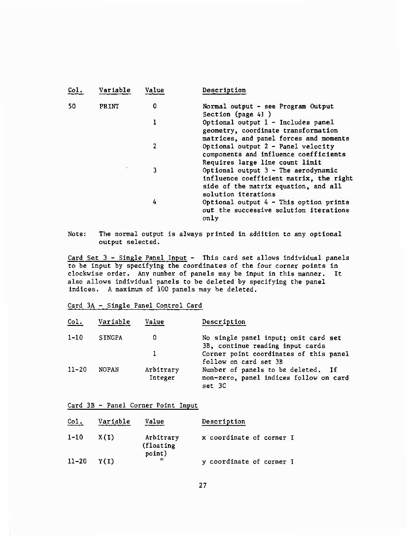
50 PRINT 0 Normal output - see Program Output Section (page 41 )
1 Optional output 1 - Includes panel geometry, coordinate transformation matrices, and panel forces and moments
2 Optional output 2 - Panel velocity components and influence coefficients Requires large line count limit
3 Optional output 3 - The aerodynamic influence coefficient matrix, the right side of the matrix equation, and all solution iterations
4 Optional output 4 - This option prints out the successive solution iterations only
Note: The normal output is always printed in addition to any optional output selected.
Card Set 3 - Single Panel Input - This card set allows individual panels to be input by specifying the coordinates of the four corner points in clockwise order. Any number of panels may be input in this manner. It also allows individual panels to be deleted by specifying the panel indices. A maximum of 100 panels may be deleted.
Card 3A - Single Panel Control Card
Col. Variable
1-10 SINGPA
11-20 NOPAN
Value
Arbitrary Integer
Description
No single panel inputj omit card set 3B, continue reading input cards Corner point coordinates of this panel follow on card set 3B Number of panels to be deleted. If non-zero, panel Indices follow on card set 3C
Card 3B - Panel Corner Point Input
Col. Variable Value Description
1-10 X(I) Arbitrary x coordinate of corner I
11-20 Y(I)
Arbitrary (floating point)
y coordinate of corner I
27
Col. Variable Value
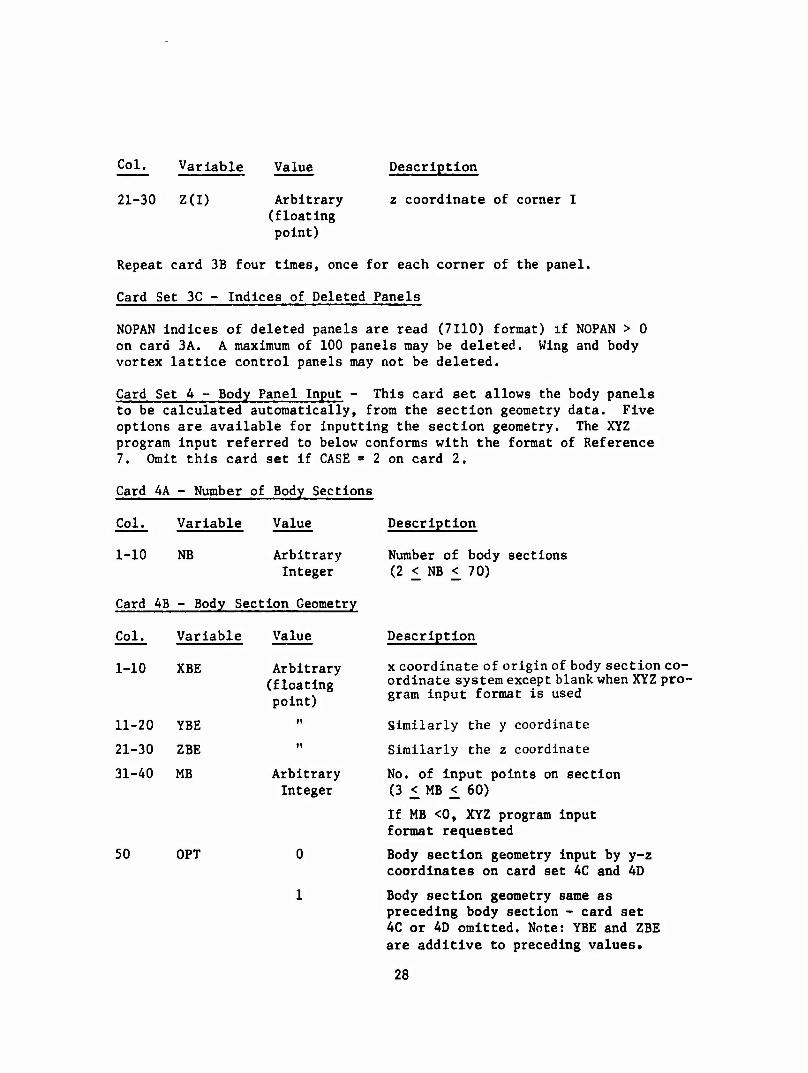
21-30 Z(I) Arbitrary (floating point)
Description
z coordinate of corner I
Repeat card 3B four times, once for each corner of the panel.
Card Set 3C - Indices of Deleted Panels
NOPAN indices of deleted panels are read (7110) format) if NOPAN > 0 on card 3A. A maximum of 100 panels may be deleted. Wing and body vortex lattice control panels may not be deleted.
Card Set 4 - Body Panel Input - This card set allows the body panels to be calculated automatically, from the section geometry data. Five options are available for Inputting the section geometry. The XYZ program input referred to below conforms with the format of Reference 7. Omit this card set if CASE » 2 on card 2.
Card 4A - Number of Body Sections
Col. Variable Value
1-10 NB Arbitrary Integer
Card 4B - Body Section Geometry
Col. Variable Value
1-10 XBE
11-20 YBE
21-30 ZBE
31-40 MB
50 OPT
Arbitrary (floating point)
Arbitrary Integer
0
1
Description
Number of body sections (2 < NB < 70)
Description
x coordinate of origin of body section co- ordinate system except blank, when XYZ pro- gram input format is used
Similarly the y coordinate
Similarly the z coordinate
No. of input points on section (3 < MB < 60)
If MB <0, XYZ program input format requested
Body section geometry input by y-z coordinates on card set 4C and 4D
Body section geometry same as preceding body section - card set 4C or 4D omitted. Note: YBE and ZBE are additive to preceding values.
28
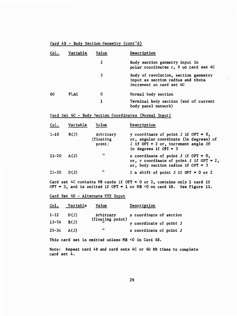
Card AB - Body Section Geometry (cont'd)
Col. Variable Value Description
Body section geometry input in polar coordinates r, 6 on card set AC
Body of revolution, section geometry input as section radius and theta increment on card set 4C
60 FLAG 0 Normal body section
1 Terminal body section (end of current body panel network)
Card Set 4C - Body Section Coordinates (Normal Input)
Col. Variable Value Description
1-10 B(J) Arbitrary y coordinate of point J if OPT - 0, (floating or, angular coordinate (in degrees) of point) J if OPT ■ 2 or, increment angle AS
in degrees if OPT - 3
11-20 A(J) " z coordinate of point J if OPT - 0, or, r coordinate of point J if OPT » 2, or, body section radius if OPT = 3
21-30 D(J) " Ax shift of point J if OPT - 0 or 2
Card set AC contains MB cards if OPT ■» 0 or 2, contains only 1 card if OPT - 3, and is omitted if OPT - 1 or MB <0 on card AB. See Figure 11.
Card Set AD - Alternate XYZ Input
Col. Variable Value Description
1-12 D(J) Arbitrary x coordinate of section ii o/ 1,/TN (floating point) 13-24 B(J) " y coordinate of point J
25-30 A(J) " z coordinate of point J
This card set is omitted unless MB <0 in Card AB.
Note: Repeat card AB and card sets AC or AD NB times to complete card set A.
29
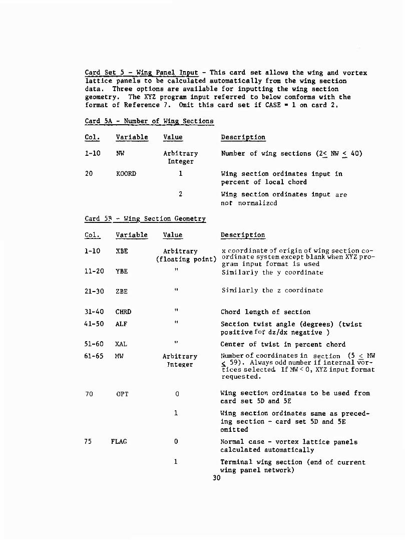
Card Set 5 - Wing Panel Input - This card set allows the wing and vortex lattice panels to be calculated automatically from the wing section data. Three options are available for inputting the wing section geometry. The XYZ program input referred to below conforms with the format of Reference 7. Omit this card set if CASE ■ 1 on card 2.
Card 5A - Number of Wing Sections
Col. Variable Value
1-10
20
NW
KOORD
Arbitrary Integer
1
2
Card 5P - Wing Section Geometry
Col.
1-10
11-20
Variable
XBE
Value
Arbitrary (floating point)
YBE
Description
Number of wing sections (2£ NW £ 40)
Wing section ordinates input in percent of local chord
Wing section ordinates input are not normalized
Description
x coordinate of origin of wing section co- ordinate system except blank when XYZ pro- gram input format is used Similarly the y coordinate
21-30 ZBE Similarly the z coordinate
31-40 CHRD ii
41-50 ALF ii
51-60 XAL II
61-65 MW Arbitrary Integer
70 OPT 0
1
75 FLAG 0
1
30
Chord length of section
Section twist angle (degrees) (twist positivefof dz/dx negative )
Center of twist in percent chord
Number of coordinates in section (5 £ MW ^ 59) . Always odd number if internal vor- tices selected If MW < 0, XYZ input format requested.
Wing section ordinates to be used from card set 5D and 5E
Wing section ordinates same as preced- ing section - card set 5D and 5E omitted
Normal case - vortex lattice panels calculated automatically
Terminal wing section (end of current wing panel network)
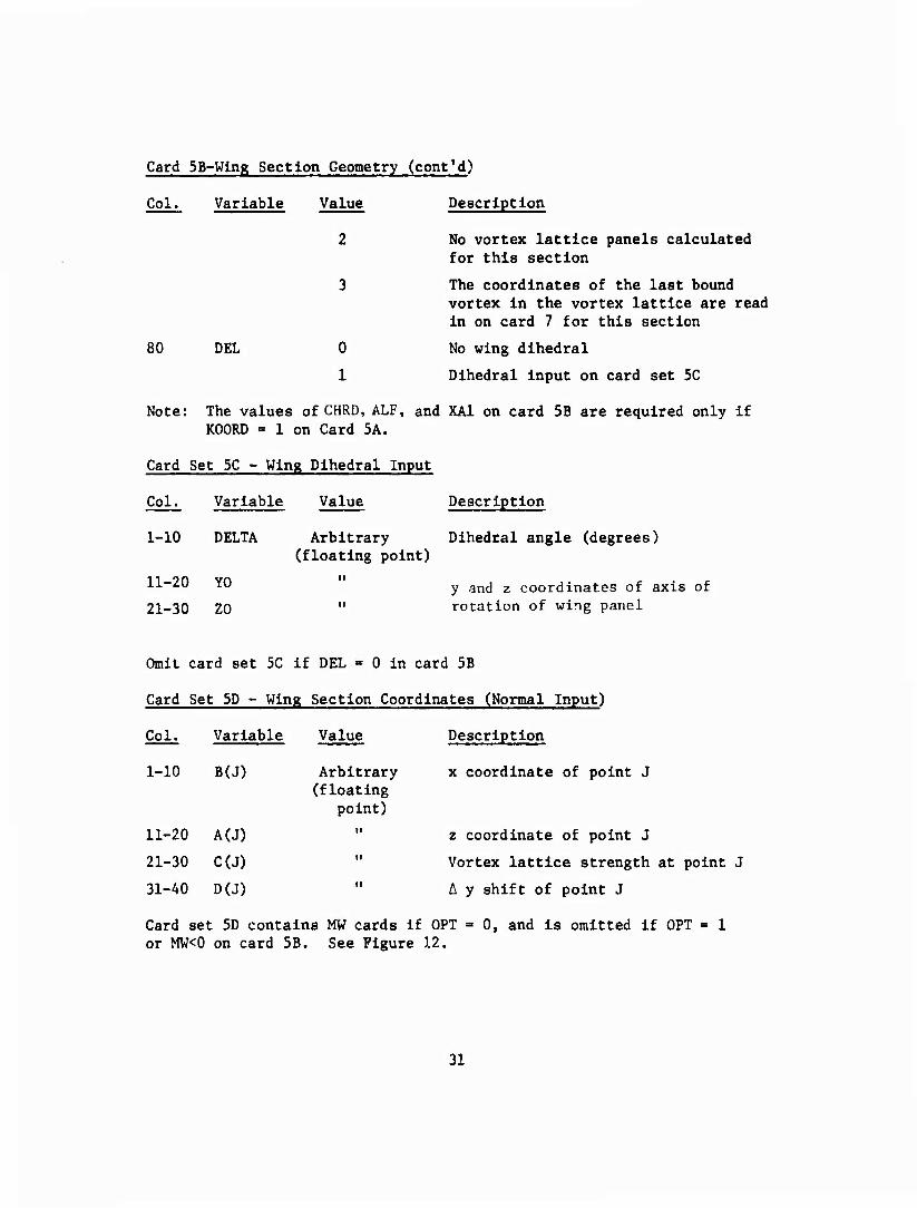
Card 5B-Wing Section Geometry (cont'd)
Col. Variable Value Description
2 No vortex lattice panels calculated for this section
3 The coordinates of the last bound vortex in the vortex lattice are read in on card 7 for this section
80 DEL 0 No wing dihedral
1 Dihedral input on card set 5C
Note: The values of CHRD, ALF, and XA1 on card 5B are required only if KOORD = 1 on Card 5A.
Card Set 5C - Wing Dihedral Input
Col. Variable Value Description
1-10 DELTA Arbitrary Dihedral angle (degrees) (floating point)
11-20 YD y gncj 2 coordinates of axis of
21-30 ZO " rotation of wing panel
Omit card set 5C if DEL = 0 in card 5B
Card Set 5D - Wing Section Coordinates (Normal Input)
Description
x coordinate of point J
z coordinate of point J
Vortex lattice strength at point J
A y shift of point J
Card set 5D contains MW cards if OPT - 0, and is omitted if OPT = 1 or MW<0 on card 5B. See Figure 12.
Col. Variable Value
1-10 B(J) Arbitrary (floating
point)
11-20 A(J) ii
21-30 C(J) ii
31-40 D(J) II
31
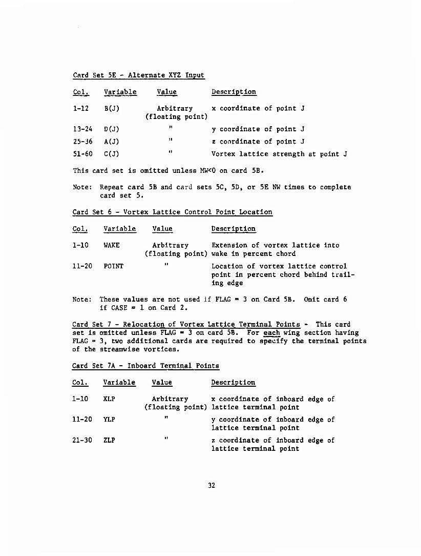
Card Set 5E - Alternate XYZ Input
Col. Variable Value Description
1-12 B(J) Arbitrary x coordinate of point J (floating point)
13-24 D(J) " y coordinate of point J
25-36 A(J) " z coordinate of point J
51-60 C(J) " Vortex lattice strength at point J
This card set is omitted unless MW<0 on card 5B.
Note: Repeat card 5B and card sets 5C, 5D, or 5E NW times to complete card set 5.
Card Set 6 - Vortex Lattice Control Point Location
Col. Variable Value Description
1-10 WAKE Arbitrary Extension of vortex lattice into (floating point) wake in percent chord
11-20 POINT " Location of vortex lattice control point in percent chord behind trail- ing edge
Note: These values are not used if FLAG = 3 on Card 5B. Omit card 6 if CASE = 1 on Card 2.
Card Set 7 - Relocation of Vortex Lattice Terminal Points - This card set is omitted unless FLAG = 3 on card 5B. For each wing section having FLAG ■ 3, two additional cards are required to specify the terminal points of the streamwise vortices.
Card Set 7A - Inboard Terminal Points
Col. Variable Value Description
1-10 XLP Arbitrary x coordinate of inboard edge of (floating point) lattice terminal point
11-20 YLP " y coordinate of inboard edge of lattice terminal point
21-30 ZLP " z coordinate of inboard edge of lattice terminal point
32
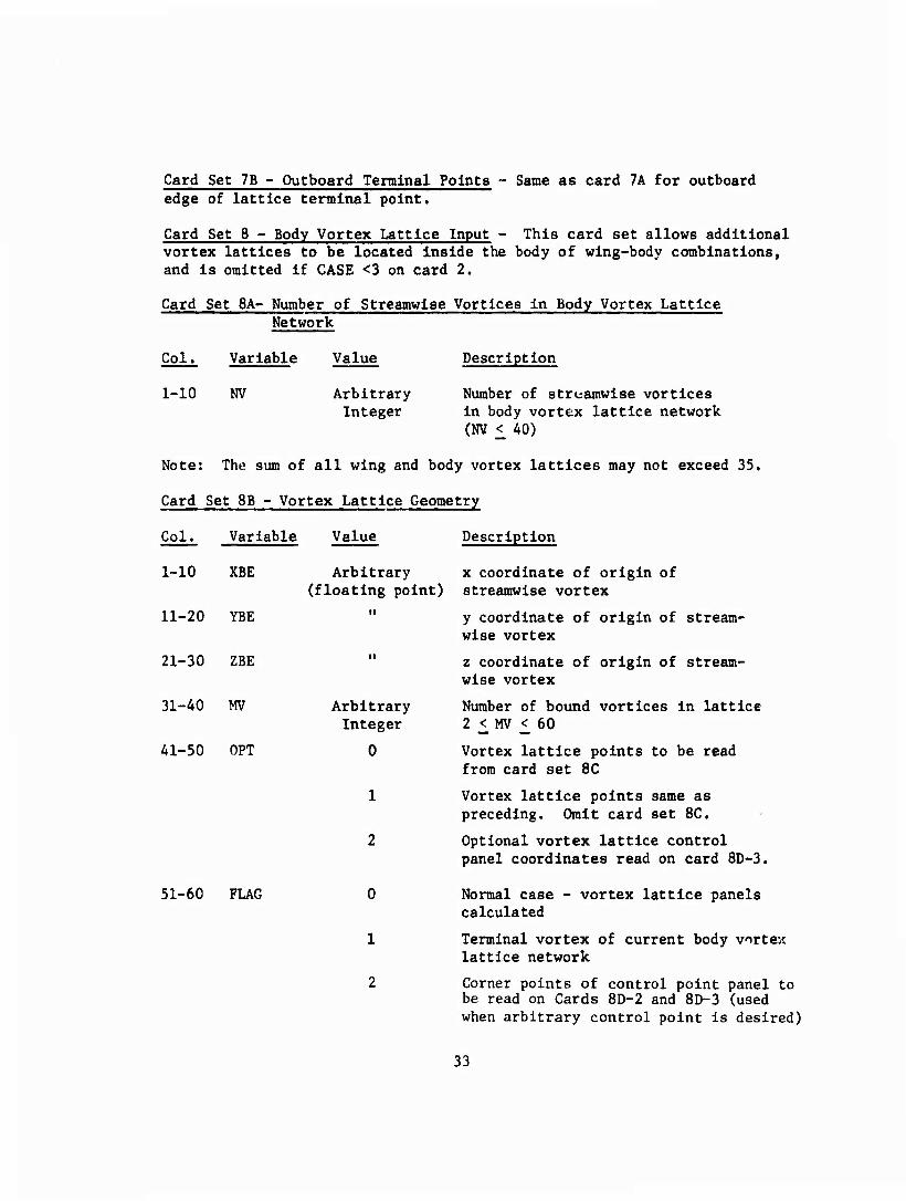
Card Set 7B - Outboard Terminal Points - Same as card 7A for outboard edge of lattice terminal point.
Card Set 8 - Body Vortex Lattice Input - This card set allows additional vortex lattices to be located inside the body of wing-body combinations, and is omitted if CASE <3 on card 2.
Card Set 8A- Number of Streamwise Vortices in Body Vortex Lattice Network
Col. Variable Value Description
1-10 NV Arbitrary Number of streamwise vortices Integer in body vortex lattice network
(NV < 40)
Note: The sum of all wing and body vortex lattices may not exceed 35.
Card Set SB - Vortex Lattice Geometry
Col. Variable Value Description
Arbitrary x coordinate of origin of (floating point) streamwise vortex
" y coordinate of origin of stream- wise vortex
z coordinate of origin of stream- wise vortex
Arbitrary Number of bound vortices in lattice Integer 2 £ MV < 60
0 Vortex lattice points to be read from card set 8C
1 Vortex lattice points same as preceding. Omit card set 8C.
2 Optional vortex lattice control panel coordinates read on card 8D-3.
51-60 FLAG 0 Normal case - vortex lattice panels calculated
1 Terminal vortex of current body vortex lattice network
2 Corner points of control point panel to be read on Cards 8D-2 and 8D-3 (used when arbitrary control point is desired)
33
1-10 XBE
11-20 YBE
21-30 ZBE
31-40 MV
41-50 OPT
Card Set 8B - Vortex Lattice Geometry (cont'd)
Col. Variable Value Description
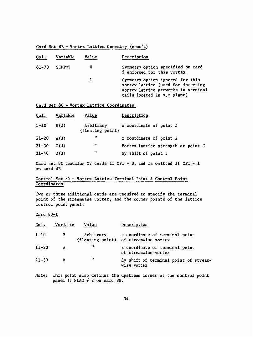
61-70 SIMPOT 0 Synmetry option specified on card 2 enforced for this vortex
1 Symmetry option Ignored for this vortex lattice (used for inserting vortex lattice networks in vertical tails located in x,z plane)
Card Set 8C - Vortex Lattice Coordinates
Col. Variable Value Description
1-10 B(J) Arbitrary x coordinate of point J (floating point)
11-20 A(J) " z coordinate of point J
21-30 C(J) " Vortex lattice strength at point J
31-40 D(J) " Ay shift of point J
Card set 8C contains MV cards if OPT = 0, and Is omitted if OPT = 1 on card SB.
Control Set 8D - Vortex Lattice Terminal Point & Control Point Coordinates
Two or three additional cards are required to specify the terminal point of the streamwise vortex, and the comer points of the lattice control point panel.
Description
Card 8D- -1
Col. Variable
1-10 B
11-20 A
21-30 D
Arbitrary x coordinate of terminal point (floating point) of streamwise vortex
" z coordinate of terminal point of streamwise vortex
Ay shift of terminal point of stream- wise vortex
Note: This point also defines the upstream corner of the control point panel If FLAG ^ 2 on card 8B.
34
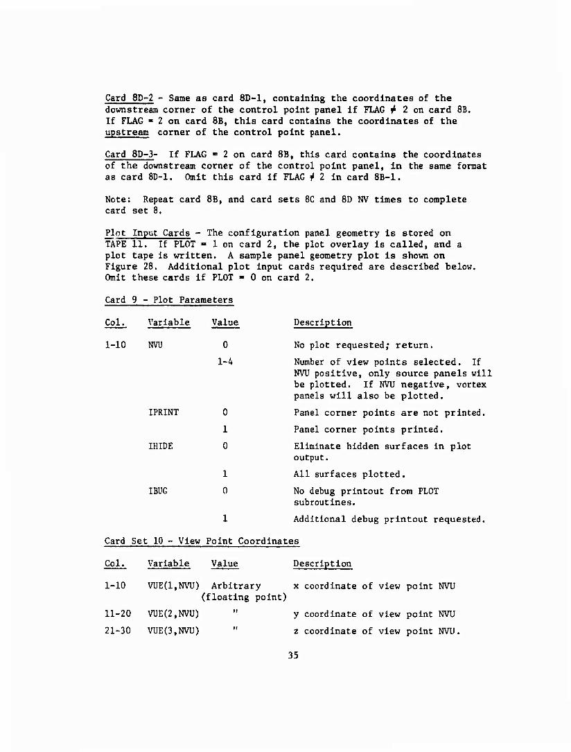
Card 8D-2 - Same as card 8D-1, containing the coordinates of the downstream corner of the control point panel If FLAG ^ 2 on card 8B, If FLAG = 2 on card 8B, this card contains the coordinates of the upstream corner of the control point panel.
Card 8D-3- If FLAG >= 2 on card SB, this card contains the coordinates of the dovmstream corner of the control point panel, in the same format as card 8D-1. Omit this card if FLAG j 2 in card 8B-1.
Note: Repeat card SB, and card sets 8C and SD NV times to complete card set 8.
Plot Input Cards - The configuration panel geometry is stored on TAPE 11. If PLOT = 1 on card 2, the plot overlay is called, and a plot tape is written. A sample panel geometry plot is shown on Figure 28. Additional plot input cards required are described below. Omit these cards if PLOT = 0 on card 2.
Card 9 - Plot Parameters
Col. Variable Value Description
1-10 NVU 0 No plot requested; return.
1-4 Number of view points selected. If NVU positive, only source panels will be plotted. If NVU negative, vortex panels will also be plotted.
IPRINT 0 Panel corner points are not printed.
1 Panel corner points printed.
IHIDE 0 Eliminate hidden surfaces in plot output.
1 All surfaces plotted.
IBUG 0 No debug printout from PLOT subroutines.
1 Additional debug printout requested.
Card Set 10 - View Point Coordinates
Col. Variable Value Description
1-10 VUE(1,NVU) Arbitrary x coordinate of view point NVU (floating point)
11-20 VUE(2,NVU) " y coordinate of view point NVU
21-30 VUE(3,NVU) " z coordinate of view point NVU.
35
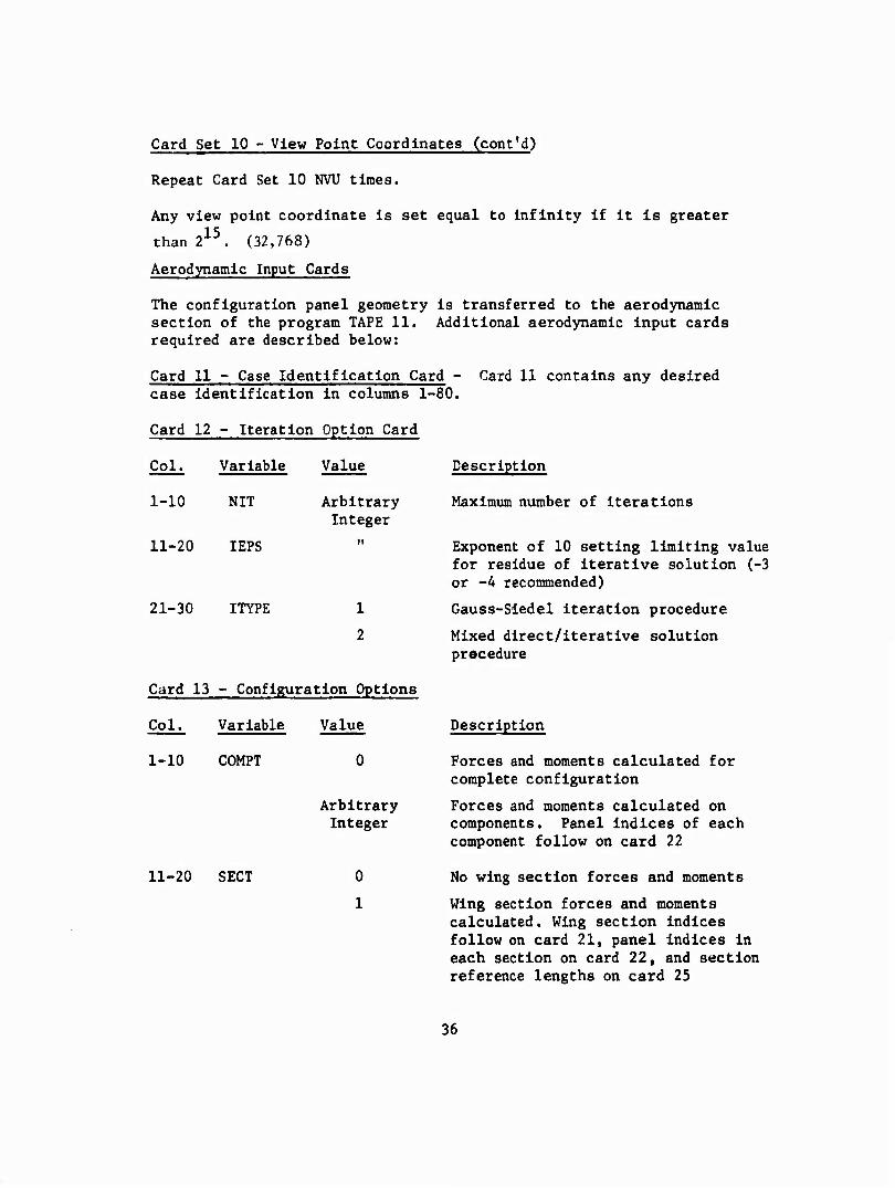
Card Set 10 - View Point Coordinates (cont'd)
Repeat Card Set 10 NVU times.
Any view point coordinate Is set equal to Infinity If It is greater
than 215. (32,768)
Aerodynamic Input Cards
The configuration panel geometry is transferred to the aerodynamic section of the program TAPE 11. Additional aerodynamic input cards required are described below:
Card 11 - Case Identification Card - Card 11 contains any desired case identification in columns 1- ■80.
Card 12 - Iteration Option Card
Col. Variable Value Description
1-10 NIT Arbitrary Integer
Maximum number of iterations
11-20 IEPS ii Exponent of 10 setting limit
21-30 ITYPE 1
2
Card 13 - Configuration Options
Col. Variable Value
1-10 COMPT
11-20 SECT
Arbitrary Integer
0
1
for residue of iterative solution (-3 or -4 recommended)
Gauss-Sledel Iteration procedure
Mixed direct/iterative solution procedure
Description
Forces and moments calculated for complete configuration
Forces and moments calculated on components. Panel Indices of each component follow on card 22
No wing section forces and moments
Wing section forces and moments calculated. Wing section indices follow on card 21, panel indices in each section on card 22, and section reference lengths on card 25
36
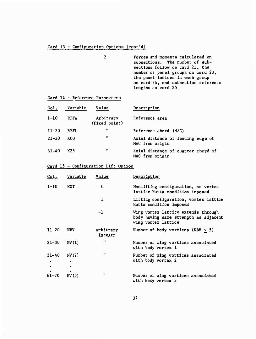
Card 13 - Configuration Options (cont'd)
Card 14 - Reference Parameters
Forces and moments calculated on subsections. The number of sub- sections follow on card 21, the number of panel groups on card 23, the panel indices in each group on card 24, and subsection reference lengths on card 25
Col.
1-10
11-20
21-30
Variable
REFA
REFI
XGO
Value
Arbitrary (fixed point)
31-40 X25
Description
Reference area
Reference chord (MAC)
Axial distance of leading edge of MAC from origin
Axial distance of quarter chord of MAC from origin
Card 15 - Configuration Lift Option
Col.
1-10
Variable
KUT
11-20 NBV
21-30 NV(1)
31-40 NV(2)
Value
-1
Arbitrary Integer
Description
Nonlifting configuration, no vortex lattice Kutta condition imposed
Lifting configuration, vortex lattice Kutta condition imposed
Wing vortex lattice extends through body having same strength as adjacent wing vortex lattice
Number of body vortices (NBV < 5)
Number of wing vortices associated with body vortex 1
Number of wing vortices associated with body vortex 2
61-70 NV(5) Number of wing vortices associated with body vortex 5
37
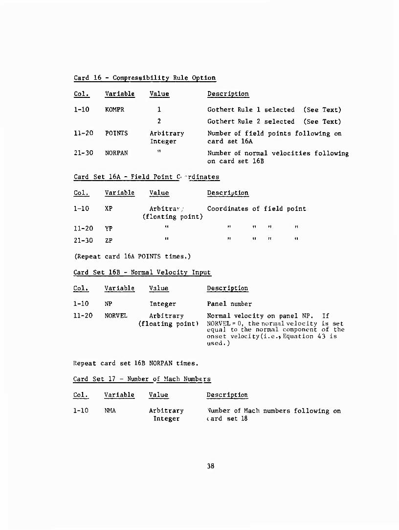
Card 16 - Compressibility Rule Option
Col.
1-10
Variable
KOMPR
11-20 POINTS
21-30 NORPAN
Value
1
2
Arbitrary Integer
it
Description
Gothert Rule 1 selected (See Text)
Gothert Rule 2 selected (See Text)
Number of field points following on card set 16A
Number of normal velocities following on card set 16B
Card Set 16A - Field Point C rdlnates
Col.
1-10
Variable
XP
Value
Arbiträr; (floating point)
Description
Coordinates of field point
ii_20 YP " " " " "
21-30 ZP " " " " "
(Repeat card 16A POINTS times.)
Card Set 16B - Normal Velocity Input
Col. Variable Value Description
1-10 NP Integer Panel number
11-20 N0RVEL Arbitrary Normal velocity on panel NP. If (floating point) NORVEL = 0, the normal velocity is set
equal to the normal component of the onset velocity(i.e.jEquation 43 is used. )
Repeat card set 16B NORPAN times.
Card Set 17 - Number of Mach Numbers
Col.
1-10
Variable
NMA
Value Description
Arbitrary dumber of Mach numbers following on Integer card set 18
38
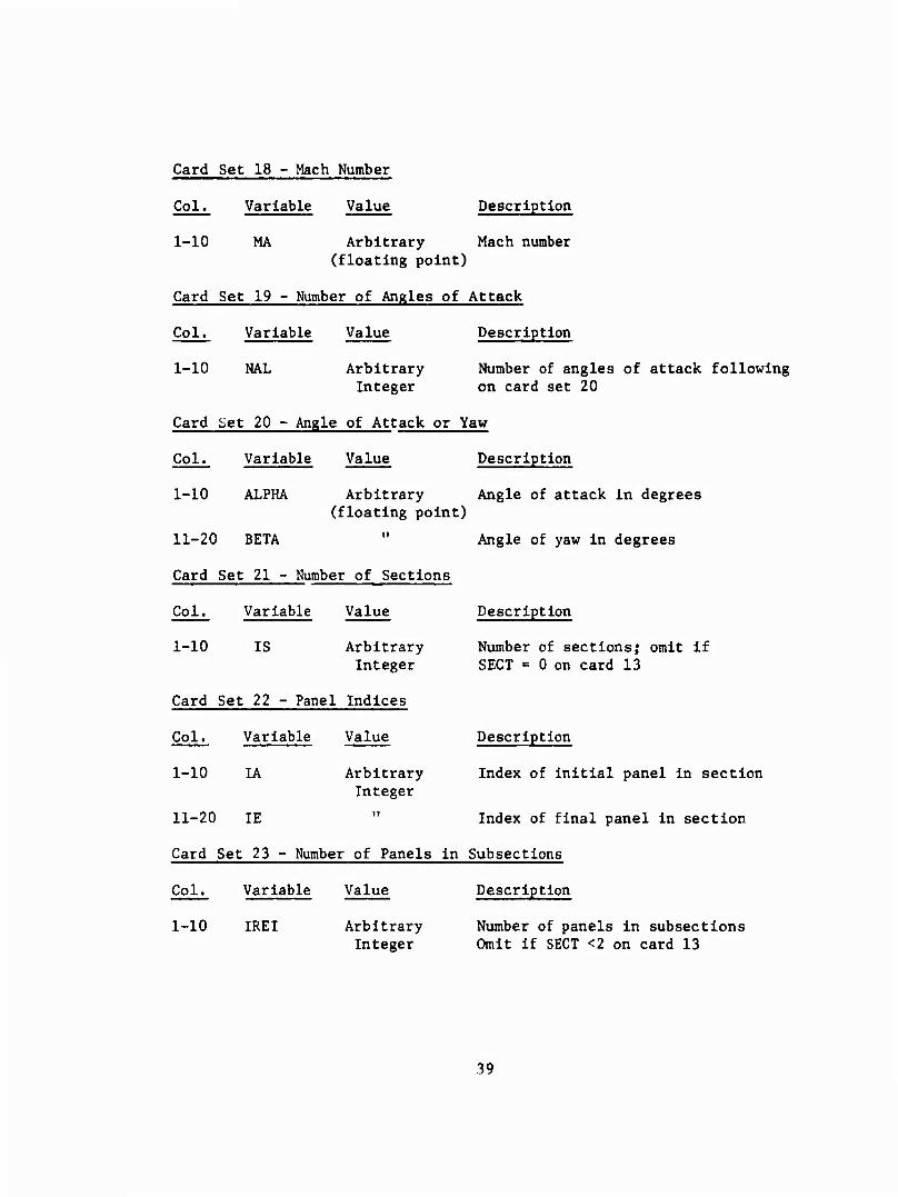
Card Set 18 - Mach Number
Col. Variable Value Description
1-10 MA Arbitrary Mach number (floating point)
Card Set 19 - Number of Angles of Attack
Col. Variable Value Description
1-10 NAL Arbitrary Number of angles of attack following Integer on card set 20
Card Set 20 - Angle of Attack or Yaw
Col. Variable Value Description
1-10 ALPHA Arbitrary Angle of attack in degrees (floating point)
11-20 BETA " Angle of yaw in degrees
Card Set 21 - Number of Sections
Col. Variable Value Description
1-10 IS Arbitrary Number of sections; omit if Integer SECT = 0 on card 13
Card Set 22 - Panel Indices
Col. Variable Value Description
1-10 IA Arbitrary Index of initial panel in section Integer
11-20 IE " Index of final panel in section
Card Set 23 - Number of Panels in Subsections
Col. Variable Value Description
1-10 IREI Arbitrary Number of panels in subsections Integer Omit if SECT <2 on card 13
39
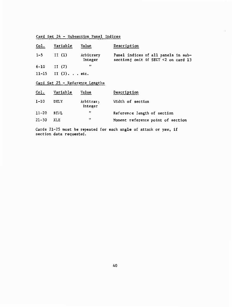
Card Set 2A - Subsection Panel Indices
Col.
1-5
Variable
II (1)
Value
Arbitrary Integer
Description
Panel indices of all panels in sub- section; omit if SECT <2 on card 13
6-10 II (2)
11-15 II (3). . . etc.
Card Set 25 - Reference Lengths
Col. Variable Value
1-10 DELY Arbitral) Integer
11-20 REFL ii
21-30 XLE it
Description
Width of section
Reference length of section
Moment reference point of section
Cards 21-25 must be repeated for each angle of attack or yaw, if section data requested.
40
PROGRAM OUTPUT
The standard output of the program consists of a list of the input cards, a table of panel points, a table of velocities and pressure coefficients at panel control points, and a force and moment summary. Additional output may be obtained by selecting appropriate values of the integer PRINT. A sample output is given in Appendix IV.
PRINT = 1 Tables of panel corner points, centroids, and the panel coordinate transformation matrix are printed out. Individual panel forces and moments are also printed out.
PRINT « 2 Tables of panel velocity components and influence coefficients are printed out. This option requires a large line count limit.
PRINT =■ 3 The aerodynamic influence coefficient matrix is printed out in row order, together with the right side of the matrix equation, and all solution iterations.
PRINT = 4 This option prints out the successive solution iterations only.
PROGRAM TIME ESTIMATION
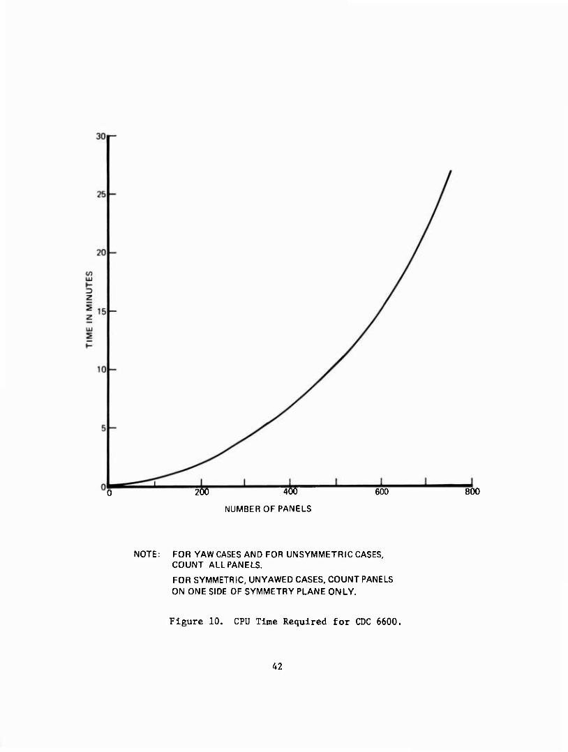
Estimates of the CPU time required by the CDC 6600 computer to calculate the aerodynamic matrix and solve for one angle of attack or yaw are presented on Figure 10. If the configuration is symmetric about the x,z plane and the yaw angle is zero, the flow is symmetric. Use of this fact by the program reduces the running time. This reduction is reflected in Figure 10 by the fact that only the number of source and vortex panels on one side of the x,z plane are counted for the symmetric flow case.
PROGRAM USAGE
The success of this method of analysis depends to a large extent on the choice of the number and location of panels used to represent the configuration. Certain features of the program input will be described in this section, together with recommendations on program usage.
Body Input
The body is described by a series of cross-sections given at selected intervals along its length. The surface panels are located between
41
200 400
NUMBER OF PANELS
600 800
NOTE: FOR YAW CASES AND FOR UNSYMMETRIC CASES, COUNT ALL PANELS.
FOR SYMMETRIC, UNYAWED CASES, COUNT PANELS ON ONE SIDE OF SYMMETRY PLANE ONLY.
Figure 10. CPU Time Required for CDC 6600.
A2
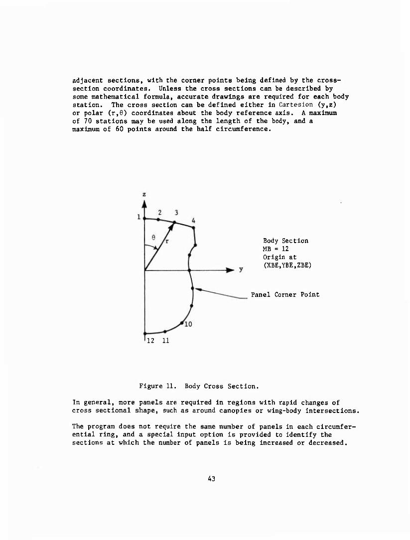
adjacent sections, with the corner points being defined by the cross- section coordinates. Unless the cross sections can be described by some mathematical formula, accurate drawings are required for each body station. The cross section can be defined either In Cartesion (y,z) or polar (r,6) coordinates about the body reference axis. A maximum of 70 stations may be used along the length of the body, and a maximum of 60 points around the half circumference.
Body Section MB • 12 Origin at (XBE.YBE.ZBE)
Panel Corner Point
12 11
Figure 11. Body Cross Section.
In general, more panels are required in regions with rapid changes of cross sectional shape, such as around canopies or wing-body intersections.
The program does not require the same number of panels in each circumfer- ential ring, and a special input option is provided to identify the sections at which the number of panels is being increased or decreased.
43
In addition, the panel corners may be shifted lengthwise out of the plane of the defining section. This option allows more freedom for paneling complex wing-body intersections and fairings.
Wing Input
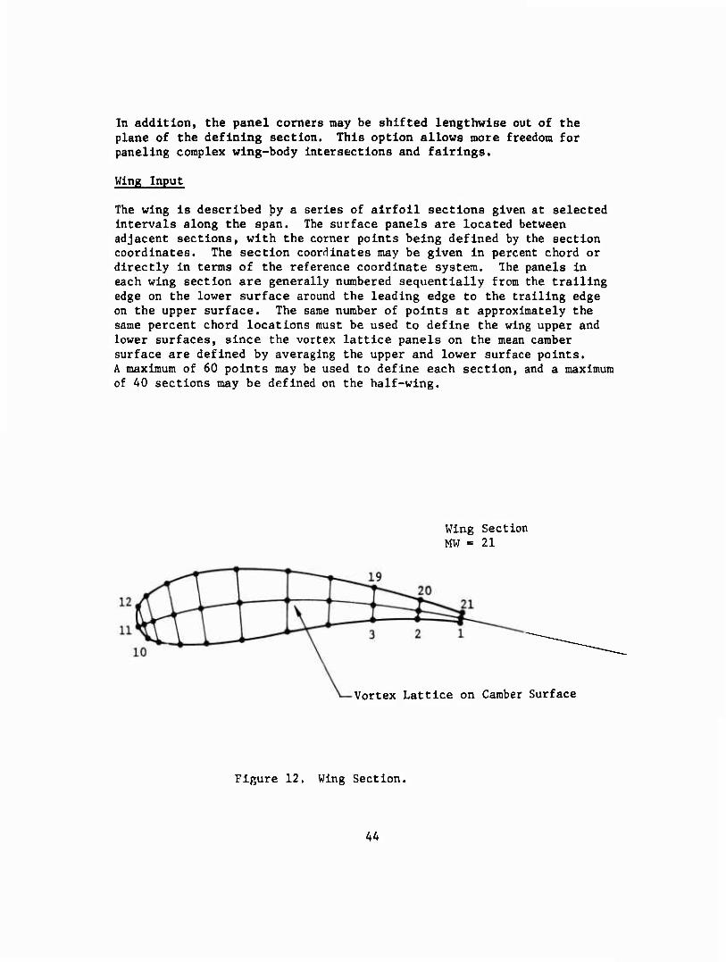
The wing is described by a series of airfoil sections given at selected intervals along the span. The surface panels are located between adjacent sections, with the corner points being defined by the section coordinates. The section coordinates may be given in percent chord or directly in terms of the reference coordinate system. The panels in each wing section are generally numbered sequentially from the trailing edge on the lower surface around the leading edge to the trailing edge on the upper surface. The same number of points at approximately the same percent chord locations must be used to define the wing upper and lower surfaces, since the vortex lattice panels on the mean camber surface are defined by averaging the upper and lower surface points. A maximum of 60 points may be used to define each section, and a maximum of 40 sections may be defined on the half-wing.
Wing Section MW = 21
Vortex Lattice on Camber Surface
Figure 12. Wing Section.
4A
The program does not require the same number of points on adjacent wing sections, and a special input option is provided to Identify the sections at which the number of panels is being Increased or decreased. In addition, the panel corners may be shifted spanwise out of the plane of the defining section to aid in the paneling of wing tips or complex wing-body intersections. In general, more panels are required in regions of rapid curvature, for example, the leading edge region.
Wing tip paneling may be omitted for wings having a maximum thickness of less than 5%. However, wing tip panels can be Included as special body panels, or read in individually using the single panel input option.
Vortex Lattice Panels
Vortex lattice panels may be placed inside either the wing or body, or omitted entirely. For configurations with a wing, the vortex lattice panels are automatically located on the mean camber surface of the wing. The vortices extend a finite distance behind the wing in a plane passing through the trailing edge and bisecting the trailing edge angle. The vortices should be allowed to extend at least ten chord lengths behind the wing to give a reasonable approximation of the wake. A control panel is associated with each vortex lattice and sized such that the panel control point is located one percent of the local chord behind the trailing edge of the wing.
The relative strengths y. of the individual bound vortices making up
the vortex lattices must be specified in advance. It is recommended that these strengths be proportional to the airfoil thickness at the chordwise location of the bound vortex. The accuracy of the final solution depends to some extent on the vortex distribution selected, so some adjustment to the bound vortex strengths may be necessary if a poor Initial choice has been made.
The program requires that the y array be read in order of Increasing chordwise station. Since the wing numbering system starts at the trailing edge, the first (M+l)/2 points are set equal to zero, and the desired y array associated with the remainder.
The structure of a vortex lattice is illustrated In the following sketch.
A5
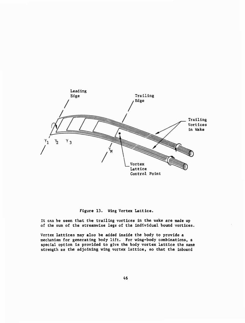
Leading Edge Trailing
Edge
/
Trailing Vortices in Wake
Vortex Lattice Control Point
Figure 13. Wing Vortex Lattice.
It can be seen that the trailing vortices in the wake are made up of the sum of the streamwise legs of the individual bound vortices.
Vortex lattices may also be added inside the body to provide a mechanism for generating body lift. For wing-body combinations, a special option is provided to give the body vortex lattice the same strength as the adjoining wing vortex lattice, so that the inboard
46
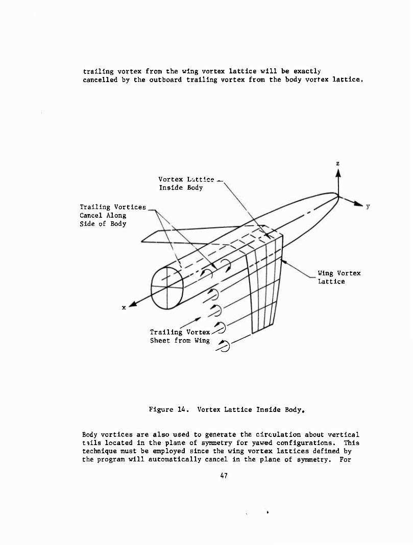
trailing vortex from the wing vortex lattice will be exactly cancelled by the outboard trailing vortex from the body vortex lattice.
Vortex Lattice Inside Body
Trailing Vortices Cancel Along Side of Body
Trailing Vortex/^ Sheet from Wing ^-v
Wing Vortex Lattice
Figure 14. Vortex Lattice Inside Body,
Body vortices are also used to generate the circulation about vertical tills located in the plane of symmetry for yawed configurations. This technique must be employed since the wing vortex lattices defined by the program will automatically cancel in the plane of symmetry. For
47
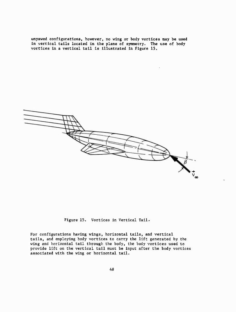
unyawed configurations, however, no wing or body vortices may be used In vertical tails located in the plane of symmetry. The use of body vortices In a vertical tail is Illustrated In Figure 15.
oo
Figure 15. Vortices In Vertical Tail.
For configurations having wings, horizontal tails, and vertical tails, and employing body vortices to carry the lift generated by the wing and horizontal tail through the body, the body vortices used to provide lift on the vertical tail must be input after the body vortices associated with the wing or horizontal tail.
A8
A GENERAL GUIDE TO PANELING WING-BODY-NACELLE CONFIGURATIONS
An input option is available to take advantage of symmetry. With the x z plane in the plane of symmetry, only the half of the configuration corresponding to positive y is required as input. This rule applies whether or not the free stream is in the plane of symmetry (i.e., with or without yaw).
When paneling a particular configuration, attention should be paid to the principal regions of interest, since this allows for optimun use of the total number of panels. A denser panel distribution should be used in the region of interest and a lesser number of panels in regions removed from this region. A sparse panel distribution has a substantial local effect. When choosing the number of panels to be used in each region, it is important to realize that the pressure calculated at the centroid of each panel is assumed to exist over the entire panel. There- fore, more panels are required in regions of large pressure gradients.
The three-dimensional potential flow program usually accepts panel corner points as inputs. An exception to this is the case where a particular section is defined as a circular arc, which may then be specified along with the number of equispaced panel corner points along the circle. The program accepts the defined panels in networks - each network defining a specific region of the configuration. The networks when assembled together define the complete configuration.
In setting up the complete paneling scheme for a wing-body-nacelle configuration, it is usually best to define the nacelle, wing, and body as separate sets of networks. The regions where two bodies inter- sect are then treated separately, and the particular networks require redefining. Any fairings that exist are treated as part of the particular configuration and not as a separate configuration. Each fairing is usually specified by its own network (or set of networks) of panels.
The body, or most likely half-body, is usually paneled by specifying the buttock line (y) and waterline (z) coordinates at each body station (x), such that at each body station the panel points are equispaced. (It is not necessary to have the panels equispaced, but it is often more convenient.)
The nacelle is paneled in a manner similar to the body.
The wing is usually paneled by specifying the x and y coordinates at each buttock line (y). When defining the panels, it must be remembered that more panels are required at the leading edge, where the pressure gradients are large. The panel size should not vary by more than 50%
49
(larger or smaller) from any adjacent panel. It is common practice to have no panel larger than 5 percent of the wing chord. Constant spacing is the optimum scheme for spanwise paneling.
The paneling at the intersection of two segments requires special care. For the case of wing-body intersection, the body panels above and below the wing must be adjusted to account for the area eliminated by the intersection. At each body station (x), the y and z coordinates are adjusted to give approximate equispacing above and below the inter- section. For the wing segment, the existing paneling can be maintained. All intersections are treated in this manner.
The wing requires a system of multihorseshoe vortices, placed inside the wing with the trailing vortices emanating from the trailing edge, to produce lift. The number of chordwise locations of the internal bound vortices are chosen to minimize large local disturbances at the wing surface. The vortices are placed along the camberline, equidistant from the nearest panel corner points in the chordwise direction.
Additional segments may be added to the configuration, such as a vertical tail and a horizontal tail. The intersections of the various segments are treated as above; and both horizontal and vertical tails will require internal vortex lattices to produce lift. No vortex lattices are placed in vertical tails located in the plane of symmetry unless the configuration is yawed.
It should be noted that, except for the simplest configurations, the preparation of the input to the three-dimensional potential flow program is cumbersome and usually almost always requires the aid of auxiliary geometry manipulation computer programs. The use of the three-dimensional plotting program is also almost essential to check the panel input data.
Save Tape Option
Since a major portion of the computer time is taken up by the calculation of the aerodynamic matrices, provision is made for saving these matrices on magnetic tape for subsequent runs on the same configuration. A new tape must be generated for each Mach number, however. The program stores the aerodynamic matrix on auxiliary disc file TAPE 10, the geometric data on auxiliary disc file TAPE 11, and the velocity component matrices on auxiliary disc file TAPE 12. If the save tape option is selected, ISAVE = -1, a magnetic tape must be designated to replace the disc file TAPE 11. The contents of TAPE 10 and TAPE 12 are also transformed to this tape during the run.
On subsequent runs, the contents of the tape must be transferred back
50
to the three disc files, and the program rerun with ISAVE = 1. Only the first two cards from the geometry input and the aerodynamic input (Cards 11-25) are required if this option is selected.
51
COMPARISON WITH EXPERIMENT
The purpose of this section is to aid the reader in the evaluation of the computer program. Discussion of comparisons between theory and experiment will be limited to two specific configurations, although many configurations have been Investigated at various times using computer program WBAERO.
BO 105 HELICOPTER CONFIGURATION
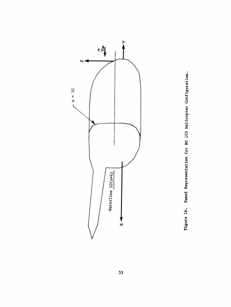
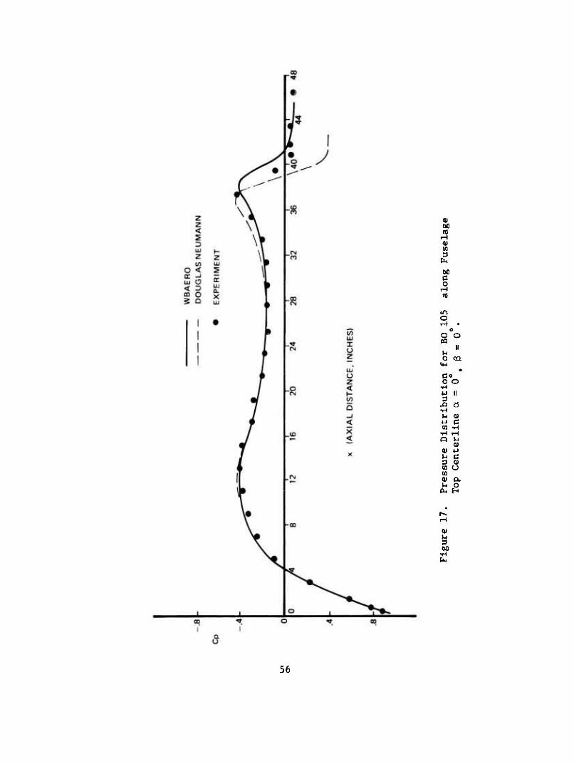
The geometry analyzed is shown in its paneled configuration in Figure 16. The number of panels on one side of the plane of symmetry is 256. The results for calculations with separation modeling were given earlier (see Figures 7 and 8) in the explanation of this modeling. Calculations with no separation modeling are compared with experimental data in Figures 17 through 20 for the cases of angle of attack a = 0°, and angle
of yaw ß = 0°, as well as a = 0°, $ = ± i0\ Calculations have also
been made by Gillespie (8) for the same configuration using the Douglas Neumann program, and these have been included for comparison purposes. In Figure 17, calculated and measured pressure coefficients are shown as a function of axial distance for the B0 105 fuselage top centerline
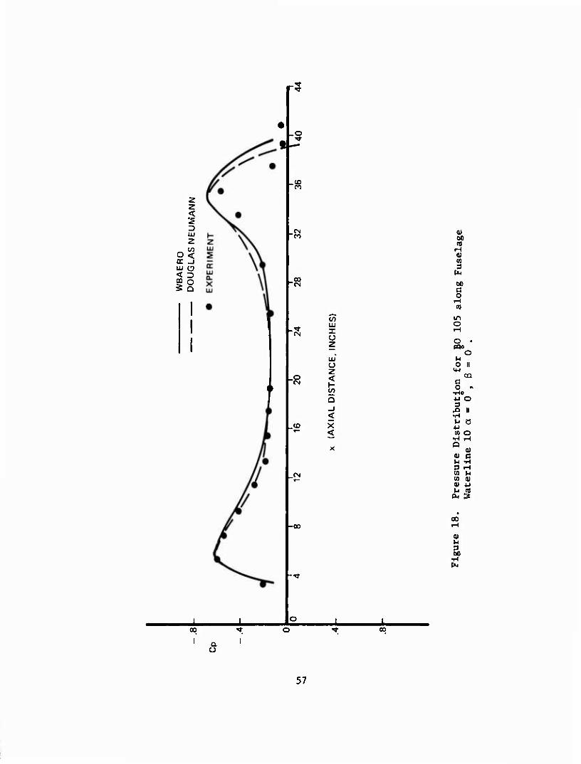
with a = 0 ,ß = 0 . Since the Douglas Neumann and WBAERO programs are fundamentally identical for the nonlifting case, it would be expected that the calculated results should be identical. On closer scrutiny, however, it is realized that the programs actually differ in two respects. First, WBAERO used the exact expression for the velocity perturbation due to a source for a greater distance away from the source panel than does the Douglas Neumann program,* and second, the iterative techniques used by each program in inverting the influence coefficient matrix are different. While the latter difference does not necessarily affect the accuracy of solution, the employment of different expressions for the velocity perturbation will most certainly affect accuracy, and it is reasonable to expect WBAERO to be slightly more accurate than the Douglas Neumann program. Such appears to be the case for the data of Figure 17, at least until the region of flow separation is approached. Comparisons are shown for the same angles of attack and yaw in Figure 18 for pressure coefficients along Waterline 10 (see Figure 16). As in Figure 17, both methods are in good agreement with experiment. A further possible reason for the slight discrepancy between the two calculation procedures results from the panel distribution used to represent the geometry. Identical panel distributions were used in each program up to axial station 32} from that point on slightly different panel arrangements were used to represent the body closure.
52
g •H U (0
•H
g u 1-1 <U u
o
o
§ •H 4-1
t 06
(0
vO
0)
53
Additional calculations were made for comparison with measurements at a = 0 f ß =10 . As shown in Figure 19, agreement between theory and experiment for pressures along the top centerline is quite good. Comparisons between theory and experiment for both windward and leeward sides of the BO 105 fuselage at Waterline 6 show good agreement as seen on Figure 20.
HEAVY LIFT HELICOPTER (HLH) CONFIGURATION
This configuration is shown as paneled in Figure 21. The number of panels on one side of the plane of symmetry is 665. In the analysis of this configuration the boundary condition discussed in the section on separation modeling was used in order that large suction pressure peaks could be avoided at sh_.p corners. In regions immediately behind
these corners the condition V • n is everywhere zero has been relaxed such
that V • n = V * n. Separated flow regions on the wings as on the 00
nacelle struts have not been modelled at this time. Calculations have been performed for zero yaw at two angles of attack, a = 0, -8 . The
results of this analysis are compared with experimental data obtained from Reference 9 at various locations on a 1/12 scale HLH configuration as shown in Figures 22 through 27. Theoretical and measured pressure coefficients along the front pylon top centerline are shown in Figure 22. Agreement between theory and experiment is quite good in the region ahead of axial station 10. At approximately that location the wind tunnel model has an attachment for the forward hub which was not modelled in the potential flow calculations. Consequently, the calculated pressures are not expected to be in close agreement with experiment in the local region behind the hub attachment. Calculations along the front pylon bottom centerline (Figure 23) give a good indication of the effect of sharp corner modelling on the comparisons with experiments. In this case the calculation by Glllespie using the XYZ program (Reference 7) shows a large suction peak around the shaxp corner of the fuselage leading to the hoist operator's observation window. The calculations using WBAER0 while showing some overshoot in pressure are in much better agreement with experiment, while at the same time taking less computer time because of the more accurate modelling of the real flow. Figures 24 and 25 give the results of comparisons between theory and experiment for the wing upper and lower surface pressures. Although separation effects were not modelled except behind sharp corners, WBAERO is generally in good agreement with experiment. Further comparisons have been made for the nacelle at the maximum spanwise location. Again, the effect of a sharp corner has been accounted for, with excellent results as shown on Figure 26. Measured and calculated pressure coefficients have also been compared along waterlines for the aft pylon. In Figure 27, the comparison is for a water line just above the
54
nacelle strut. One particularly interesting result of this comparison is the suction peak resulting from interference by the nacelle strut which is predicted by theory. Because of the choice of pressure tap locations, no indication of this peak can be obtained from data alone. If load calculations are made from such measurements, erroneous conclusions can be drawn.
SAMPLE CASE
A simple wing-body-vert leal-tail airplane configuration (Figure 28) has been analyzed as a sample case in order to demonstrate most of the program features. Because configurations having large vertical tails or pylons are expected to experience side forces under yawing conditions, it was necessary to modify the computer program in order that vortex networks could be employed to provide the correct circulation for side force calculations. Calculations are shown in Figure 29 for the pressure distribution along a waterline on the vertical tail. Two calculations are given, for the conditions ß = 0 and ß = 10 . It is
O
interesting to note that for ß = 10 the vertical tail carries a nega-
tive load on the aft portion. Slender wing theory for low aspect ratio wings suggests that there should be no load over the aft part of the wing; however. Interference with the blunt based fuselage appears to lead to the negative load.
55
<u öO n)
^H <U M 3
PM
60 c o
iH cd
m o rH •
( 3 o o PQ
II M O OQ
»4-1
Co O O
•rl W II 3
^i Ö •H M 01 iJ c U5 •H
•H iH O J-t
(U 0) 4J U c 3 0) CO O to (U o. u o
cu H
(U
00
56
.o
CO
CM TO
CO
CM
-8
_«o
.<N
(/) LU I u 2
LU O z < H
Q
< X <
-00
-f
0) 00 eo
1-1 0) (0 3
(b
60 c o
^H CO
in o .H
O * PQc
o U o II
m CQ
c o •l
•Ho U o 3
^J II •H U a u CO o
•H H O
01 0) a VJ •H 3 H M I» CO (U 0) u n CO
PL, s
00
(U u a 60
00 00
a o
57
s er LU Q. x
i)
<u 00
0) en 3
fe t>0
o rH rt
in o • iH o
o o iH CO
II M o CQ
U-l
Co o O
•rt 4J II 3 ^ Ö •H U (U u c «) •H ■H rH o U
01 (U u u G 3 (U (0 O to 0) eu u 0 s H
iH
0)
E •H
00 r a o
l"
58
CO
rH 0) (0
s I o
O PQ o
u o
o •H - 4JO 3 O
43 •H || U « Ö W
•H vo O
(U a) a U «H 3 rH CO M W (U (U -M M n
o CM
OJ M 3
59
c p
id
00
O »4-1
I 4-1 tO U
g s I H 0) c
PL!
CM
ä •rl
60
c o H
U.
<U 00
I u o
C • 0 0) n a U -H 3 H
^1 U ■H 0) H W
^g •H U Q a oi o .H
(0 C CO o 01 H
04 (U
CM CM
0)
•H fa
61
1- z LU s O
tu Q. X
or LU < CO N 5 >-
' o ' o o 00
O I Oo II II II II II
ö O ö Ö Ö
• ®
c o u
<u
«
(U (0 3
U O •
«4-1 0)
c5 O H
•H h ■U <U 3 *J ^ C •H 0) M U U co e
■H 5 o *J
4J 0) o i-i pq s CO c CO o 0) H h >.
CM
0)
62
K 2 til 5 o oc cc LU a.
LU <
X 00 N LU >
X 0 o oo o
O 00 o 1 0 1 %
II II II II II o a a a o
at o «
K-l M 3
ai a. a
60 C
•H
3 s o
3 J3
0) • U IT) 3 • (0 00 (fl 0) II
(U
E •H pi-
es
r- o ID QC
5 LU <
oc m UJ 5 Q. X LU o
' o * o «o ii ii O | O 0
II II
0) o
4-1 u 3
C/3
>-i
cu S o
c s
ä u o
§ •rl U
i (0
•H Ö
0) •
co oo to 0) II M
in
u 00
64
s o UJ
QC UJ
< X UJ
00
o
N >-
o 9 T o 1
X
Oo II II ii ii II
Ö o 0 O a
I I
o
«
o
§ •H u 3
43
3 W M 0)
65
y- o z LU UJ < m GC 5 N
> X LU
o X o ^ o UJ
II II
o II o
o « O | Ö Ö Ö
II II
Ö o 1 1
® a
1
1 1 1
"00
i »
\ E ^ \ CM > ̂
) -S/
/ J r
ä& S 4 / y* .timmi
/, if UJ y s ' I
.<X 2
r ^.^r r^
LU u z
\
<
^C ̂^^ •—* ^ ̂ ^•fc^ÜJ" «■^ o _1
^^v p^ <
X <
F X
4 CD
a fe
v\
J J
s 00 If) _J i
%
c o
rH
u S
o
c o • •H CO 4J • 3 H
^3 rH •H
4J II (0
•H O N
0) U 0) 3 rH 0) r-H CO 0) 0) Ü u nt ix z
CM
0)
ä
00
I r 00
Q.
66
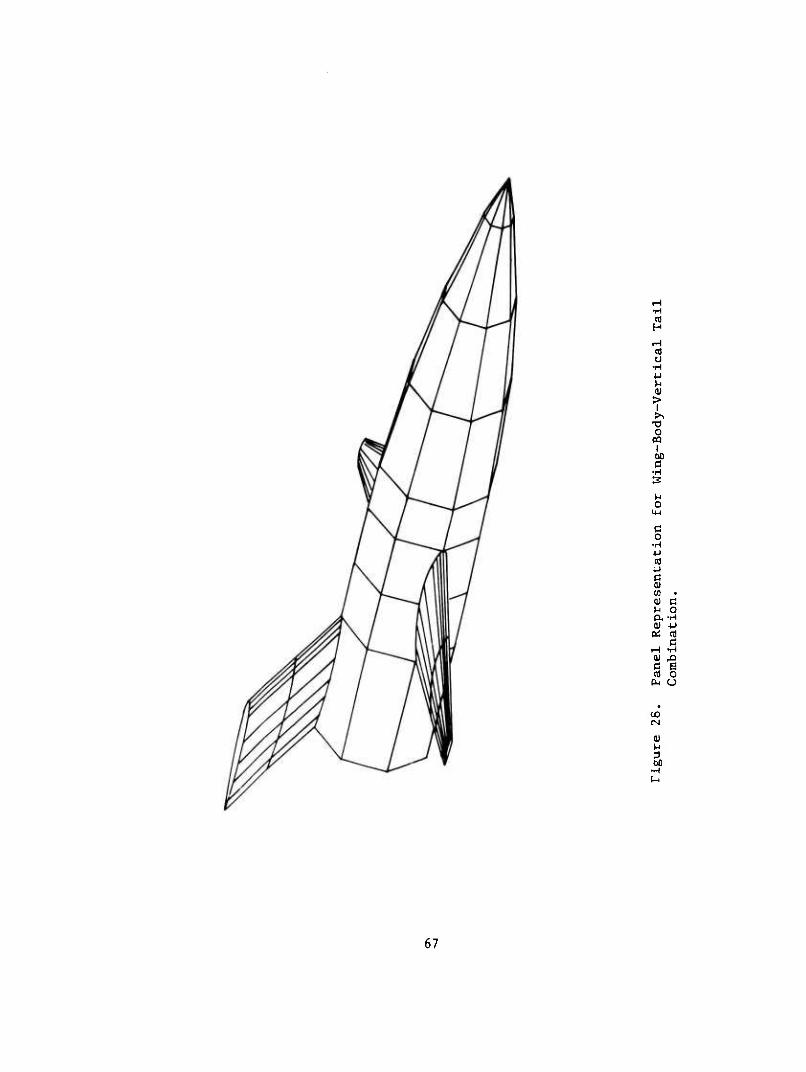
H
O •H U u
I i
u o
H-l
ß o •H 4J n)
c (U
<D c M O (X-rl 0) 4-1
(U ^3 C B tfl o
PL, u
oo CN
0) M 3 60
•H
67
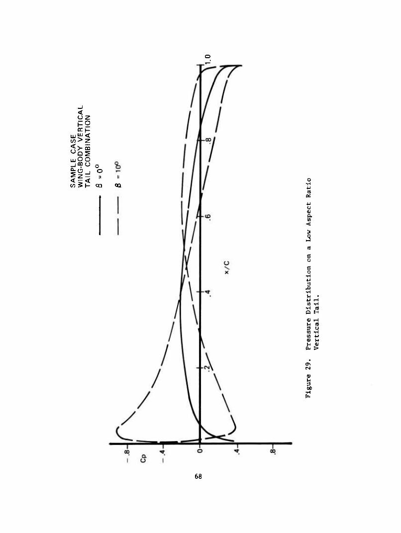
< oz
w> z <>-co
LUOO _|QQO o
o II
en
n
4J
4-1 U <u a.
•H
(0 -H •H (d O H
<U iH l-i (0 3 U W l-l (0 4-1 a) t-i u <u
P- >
0)
68
CONCLUSIONS
As a result of the studies described In this report, the following conclusions have been drawn:
1. The three-dimensional potential flow computer program provides the user with a practical and accurate method for the calculation of pressures and aerodynamic forces for arbitrary shaped lifting configurations including the effect of yaw.
2. The separation modelling proposed in this report shows encourag- ing agreement with experiment while reducing the computer time requirements for a given configuration.
69
REFERENCES
1. Kraus, W., and Sacher, P., Das MBB-Unterschall Panel Verfahren: Dreidimensionale Potentialtheroie bei beliebig Vorgegebener Mehr Korperanordnung. MBB Report UFE-672-70(0), December 1970.
2. Rubbert, P. E., Saaris, G. R., Scholey, M. B., and Standen, N. M., A General Method for Determining the Aerodynamic Characteristics of Fan-ln-Wing Configurations. Volume I - Theory and Applications, The Boeing Co., USAAVLABS TR67-61A, December 1967, AD667980.
3. Hess, J. L., and Smith, A. M. 0., Calculation of Potential Flow about Arbitrary Bodies. Progress in Aeronautical Sciences, Vol. 8, Pergamon Press, 1' 7.
4. Gothert, B., Plane and Three-Dimensional Flow at High Subsonic Speeds. NACA TM 1105, 1946.
5. Hess, J. L., and Smith, A. M. 0., Calculation of Nonllfting Potential Flow about Abrltrary Three-Dimensional Bodies. Douglas Aircraft Co., Report No. ES 40622, March 1962.
6. Labrujere, T. E., Loeve, W., and Slooff, J., An Approximate Method for the Calculation of Pressure Distribution on Wing-Body Combi- nations at Subcritlcal Speeds. AGARD Conference Proceedings No. 71, September 1971.
7. Dawson, C. W., and Dean, J. S.,The XYZ Potential Flow Program, NSRDC Report 3892, June 1972.
8. Glllesple, J., An Investigation of the Flow Field and Drag of Helicopter Fuselage Configurations. Presented at 29th Annual National Forum, American Helicopter Society, Washington, D. C, May 1973.
9. Julien, D., Wind Tunnel Test to Measure Surface Pressure Distributions on the 1/12 Scale HLH. Boeing Document D210-106771- 1, July 1973.
70
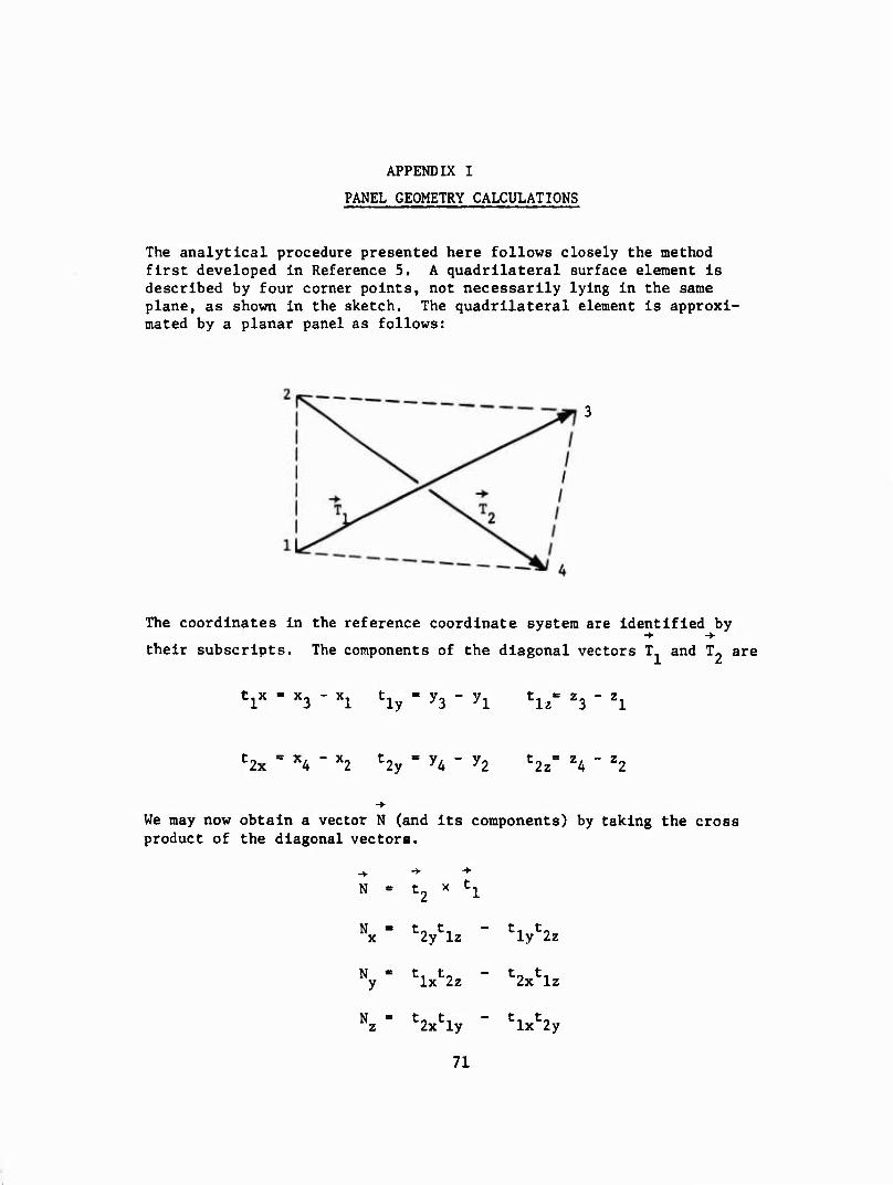
APPENDIX I
PANEL GEOMETRY CALCULATIONS
The analytical procedure presented here follows closely the method first developed In Reference 5. A quadrilateral surface element Is described by four corner points, not necessarily lying in the same plane, as shown in the sketch. The quadrilateral element is approxi- mated by a planar panel as follows:
The coordinates in the reference coordinate system are identified by
their subscripts. The components of the diagonal vectors T- and T- are
V " x3 - xl hy = ^3 " yl t, = z- - Z- Iz 3 1
t2x = XA " x2 t2y " yA " y2 Hz" Z4 - Z2
We may now obtain a vector N (and its components) by taking the cross product of the diagonal vectors.
-y
N t, - h
Nx- Viz - Vzz
N - t. t0 y Ix 2z t- t. 2x Iz
Nz- Vly " hxS
71
The unit normal vector, n, to the plane of the element is taken as N
divided by its own length |N| (direction cosines of outward unit normal).
N
"x ■ -f N
n = —^ y N
N
where
N - [N2 + N2 + N2]1/2 x y z
The plane of the element is now completely determined If a point In this plane Is specified. This point Is taken as the point whose coordinates
x, y, z are the average of the coordinates of the four input points.
i [xj^ + x2 + x3 + x4]
y - i [yx + yz + ys + y4]
i = i [z1 + Z2 + z3 + z4]
Now the input points will be projected into the plane of the element along the normal vector. The resulting points are the corner points of the quadrilateral element. The input points are equidistant from the plane, and this distance Is
d - nx(x - x^ + ny(y - y^ + ^(i - z^
72
The coordinates of the corner points In the reference coordinate system are given by
lk k+1
\ + (-i) v
k+1 yk - yk + (-1) n d
z! - zu + (-l)k+1n d
k - 1, 2, 3, 4
Now the element coordinate system must be constructed. This requires the components of three mutually perpendicular unit vectors, one of which points along each of the coordinate axis of the system, and also the coordinates of the origin of the coordinate system. All these quantities must be given in terms of the reference coordinate system. The unit normal vector is taken as one of the unit vectors, so two perpendicular unit vectors in the plane of the element are needed. Denote
-♦■-♦■ ->• ■+
these unit vectors t, and tj. The vector t, is taken as T, divided by
its own length T-, i.e.,
Ix Ix
■ly -in
where
■lz Iz
2 + T2 + T2 1/2 lllx + ^y ^z1
73
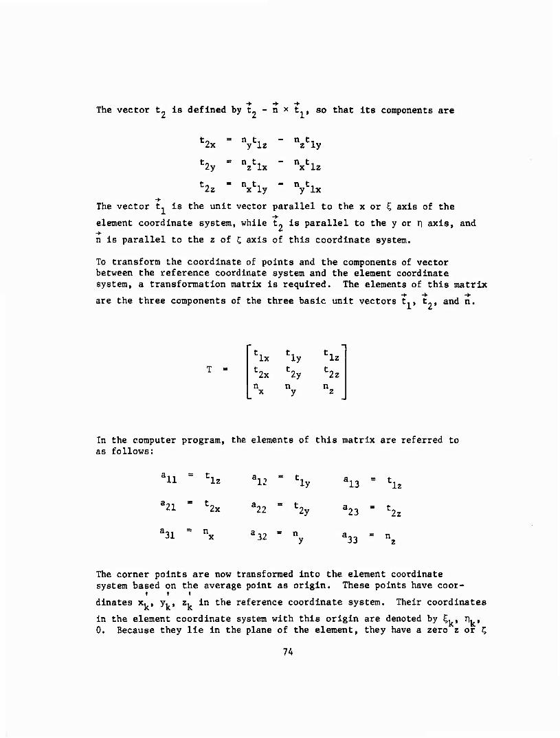
The vector t- is defined by t» - n * t-, so that its components are
c2x
to 2y
2z
n t, y Iz
- n t, z ly
= n t, - n t. z Ix x Iz
= n t.. x ly
- n t. y Ix
The vector t, is the unit vector parallel to the x or ^ axis of the ■*■
element coordinate system, while t? is parallel to the y or ri axis, and
n is parallel to the z of j; axis of this coordinate system.
To transform the coordinate of points and the components of vector between the reference coordinate system and the element coordinate system, a transformation matrix is required. The elements of this matrix
■+ -*■ -*■ are the three components of the three basic unit vectors t,, t», and n.
T = 'Ix
:2x
'ly :2y
'Iz
:2z n
In the computer program, the elements of this matrix are referred to as follows:
aii = hz a12 S 'ly a13 = hz a21 = ^x l22 ■2y 23 u2z
^l 32 a33 = nz
The corner points are now transformed into the element coordinate system based on the average point as origin. These points have coor-
dinates x. , y, , z, in the reference coordinate system. Their coordinates
in the element coordinate system with this origin are denoted by £,, rv, 0. Because they lie in the plane of the element, they have a zero z or C
7A
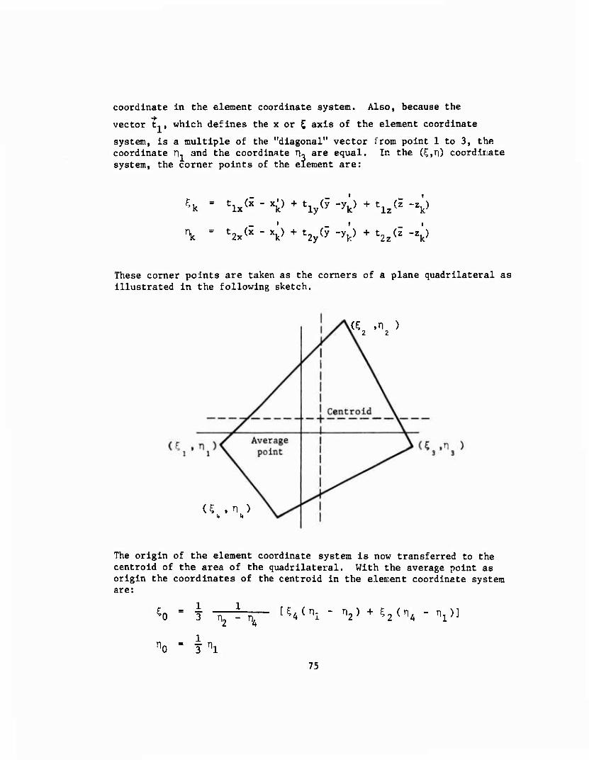
coordinate In the element coordinate system. Also, because the
vector t,, which defines the x or S axis of the element coordinate
system, Is a multiple of the "diagonal" vector from point 1 to 3, the coordinate n, and the coordinate ru are equal. In the (5,ri) coordinate system, the corner points of the element are:
\ = ^x^-V +t2y(y"^ +t2z^-Zb
These corner points are taken as the comers of a plane quadrilateral as illustrated in the following sketch.
(C .1 ) 2 2
U , n ) i« it
The origin of the element coordinate system is now transferred to the centrold of the area of the quadrilateral. With the average point as origin the coordinates of the centroid in the eletrent coordinate system are:
1 1 'Vi 3 o, - n4
K n2) + C2(n4 V:
75
These are subtracted from the coordinates of the comer points In the element coordinate system based on the average point as origin to obtain the coordinates of the corner points in the element coordinate system based on the centrold as origin. Accordingly, these latter coordinates are
^k "^ -^o
nk = nk " ^
k = 1, 2, 3, 4
Since the centrold is to be used as the control point of the element, its coordinates in the reference coordinate system are required. These coordinates are
X0 = ^ + tlx?0 + t2xn0
yo - *+ Vo+ Vo Z0 " 5 + tlz^0 + t2znO
Finally, the area of the quadrilateral is
A - I (^3 " ^^2 " n4)
76
APPENDIX II
SUBROUTINE DESCRIPTIONS
(arranged in alphabetical order)
This appendix contains a brief outline of the purpose, method, and use or each subroutine. The principal constants and variables in each are listed in the order of their first appearance, and identified as input or output data.
77
Subroutine ANALOG
Purpose:
Method:
Use:
To transform the panel control point and corner points from the real body to the analog body, as required by Gothert's compressibility rule.
The panel control point is transformed simply by multi- —
plying the y and z coordinates by B = ^ 1-M . The trans- formation matrix is then corrected for compressiblity, and new panel corner points determined in the panel reference system. Finally, the area and maximum diagonal of the panel are calculated.
Call ANALOG (BETA, YC, ZC, A, XEI, YEI, F, T)
Input:
BETA Prandtl-Glauert factor = ^ 1-M
YC y coordinate of panel control point
ZC z coordinate of panel control point
A Transformation matrix
XEI z coordinate of panel corner point in panel coordinate system
YEI y coordinate of panel corner point in panel coordinate system
Output:
YC Transformed y coordinate of panel control point
ZC Transformed z coordinate of panel control point
A Transformed transformation matrix
XEI Transformed x coordinate of panel corner point in panel coordinate system
YEI Transformed y coordinate of panel corner point in panel coordinate system
F Panel area
78
Subroutine ANALOG(cont'd)
Output:(cont'd)
T Length of maximum diagonal of panel
Subroutine Called: None
Error Returns: None
79
Subroutine DRAW3D
Purpose:
Method:
Use:
To plot the object as viewed from the viewpoints.
DRAW3D begins by projecting the object onto the display plane (the "V, W" plane) perpendicular to the vector from the origin to the viewpoint. It also generates the panels needed for symmetry if ISYM is zero. The V, W data are then scaled so that they will be plotted in an area 6.5 inches wide by 9.0 inches high.
The program then creates a new list of the panels to be plotted in the array LL. If the IHIDE parameter is zero, the new list will only have the panels that face the viewpoints, and in addition the subroutine OVRLAP will be called to eliminate any panels that are partially or entirely blocked by some other panel.
Finally, the program loops through the new list (LL) and calls the subroutine PLTPAN to plot the panels.
Call DRAV3D (N, M, VX, VY, VZ, ISYM, IHIDE, IBUG)
The number of vertices
M The number of panels
VX,VY, The coordinates of the viewpoint VZ
ISYM If zero, the object iS symmetric about the XZ plane
IHIDE If zero, the program is to eliminate the hidden surfaces
IBUG If nonzero, the coordinate of the vertices in the display plane will be printed. If IBUG = 1, the list contained in the array LL will be printed along with the corresponding coordinates in the display plane
Input:
In addition to the parameters in the calling sequence, the subroutine DRAW3D uses the data in the common arrays V, W, DIST, and L. These arrays are set up in the program WBPLOT.
80
Subroutine DRAW3D(cont'd)
Output:
The primary output of DRAW3D is the data in the common arrays V, W, DIST, and LL, which arc used by the subroutine OVRLAP and PLTPAN. In addition to this there are the optional IBUG printouts, and label on the plot.
Subroutines Used:
NUMBER Used to draw numbers on the plot
OVRLAP Used to eliminate blocked panels
PLOT Used to control the plotting origin
PLTPAN Used to draw the panels
rvMu^L Used to draw symbols on the plot
Limitations: See WBPLOT
81
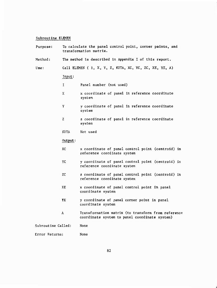
Subroutine ELEMEN
Purpose: To calculate the panel control point, corner points, and transformation matrix.
Method: The method is described in Appendix I of this report.
Use: Call ELEMEN ( I, X, Y, Z, KUTA, XC, YC, ZC, XE, YE, A)
Input:
I Panel number (not used)
X x coordinate of panel in reference coordinate system
Y y coordinate of panel in reference coordinate system
Z z coordinate of panel in reference coordinate system
KUTA Not used
Output:
XC x coordinate of panel control point (centroid) in reference coordinate system
YC y coordinate of panel control point (centroid) in reference coordinate system
ZC z coordinate of panel control point (centroid) in reference coordinate system
XE x coordinate of panel control point in panel coordinate system
YE y coordinate of panel corner point in panel coordinate system
A Transformation matrix (to transform from reference coordinate system to panel coordinate system)
Subroutine Called: None
Error Returns: None
82
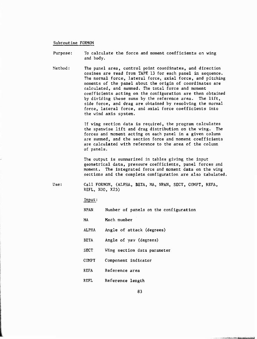
Subroutine FORMOM
Purpose: To calculate the force and moment coefficients on wing and body.
Method: The panel area, control point coordinates, and direction cosines are read from TAPE 13 for each panel in sequence. The normal force, lateral force, axial force, and pitching moments of the panel about the origin of coordinates are calculated, and summed. The total force and moment coefficients acting on the configuration are then obtained by dividing these sums by the reference area. The lift, side force, and drag are obtained by resolving the normal force, lateral force, and axial force coefficients into the wind axis system.
If wing section data is required, the program calculates the spanwise lift and drag distribution on the wing. The forces and moment acting on each panel in a given column are summed, and the section force and moment coefficients are calculated with reference to the area of the column of panels.
The output is summarized in tables giving the input geometrical data, pressure coefficients, panel forces and moment. The integrated force and moment data on the wing sections and the complete configuration are also tabulated.
Use: Call FORMOM, (ALPHA, BETA, MA, NPAN, SECT, COMPT, REFA, REEL, X00, X25)
Input:
NPAN Number of panels on the configuration
MA Mach number
ALPHA Angle of attack (degrees)
BETA Angle of yaw (degrees)
SECT Wing section data parameter
COMPT Component indicator
REFA Reference area
REFL Reference length
83
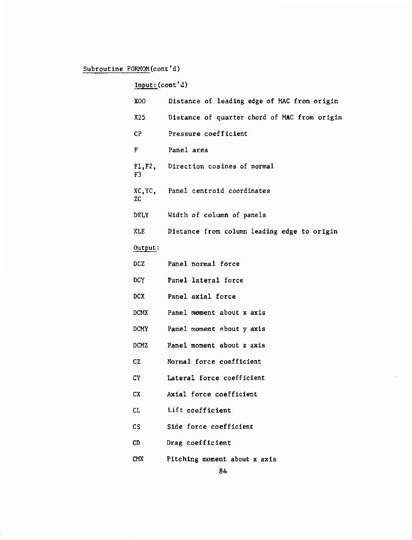
Subroutine FORMOM(cont'd)
Input;(cont'd)
X00 Distance of leading edge of MAC from origin
X25 Distance of quarter chord of MAC from origin
CP Pressure coefficient
F Panel area
F1,F2, Direction cosines of normal F3
XC,YC, Panel centroid coordinates ZC
DELY Width of column of panels
XLE Distance from column leading edge to origin
Output:
DCZ Panel normal force
DCY Panel lateral force
DCX Panel axial force
DCMX Panel moment about x axis
DCMY Panel moment f.hont y axis
DCMZ Panel moment about z axis
CZ Normal force coefficient
CY Lateral force coefficient
CX Axial force coefficient
CL Lift coefficient
CS Side force coefficient
CD Drag coefficient
CMX Pitching moment about x axis
84
Subroutine F0RM0M(cont'd)
Output(cont'd)
CMY
CMZ
DXN
CM25
CMOO
Subroutine Called:
Error Returns:
Pitching moment about y axis
Pitching moment about z axis
Center of pressure location
Pitching moment about quarter chord of MAC
Pitching moment about leading edge of MAC
None
None
85
Subroutine INPUT
Purpose: To calculate the three components of velocity Induced by a constant source distribution on a given panel.
Method: The method of Hess and Smith (Reference 1) is used. The velocity component formulas are summarized in the Aero- dynamic Theory Section of this report.
Use: Call INFLU (I, J, XE, YE, XN, YN, ZN, XC.YC, AC, A, T, F, VX.VY, VZ, SYM).
Input:
I Contro": point number
J Influencing panel number
XE x coordinate of panel corner point in panel coordinate system
YE y coordinate of panel corner point in panel coordinate system
XN x coordinate of control point I in reference coordinate system
YN y coordinate of control point I in reference coordinate system
ZN z coordinate of control point I in reference coordinate system
XC x coordinate of centroid of panel J in reference coordinate system
YC y coordinate of centroid of panel J in reference coordinate system
ZC z coordinate of centroid of panel J in reference coordinate system
A Transformation matrix of panel J
T Maximum diagonal of panel J
F Area of panel J
86
Subroutine INFLU(cont'd)
Input; (cont'd)
SYM
Output:
VX
VY
VZ
Subroutine Called:
Error Returns:
Logical variable denoting symmetry in panels about x, z plane. (SYM is true if the panel and control point lie on the same side of the plane of symmetry; SYM is false otherwise.)
x component of induced velocity (in reference coordinate system)
y component of induced velocity (in reference coordinate system)
z component of induced velocity (in reference system)
None
Calls EXIT if control point lies on edge of panel.
87
Subroutine LATICE
Purpose: To calculate the three components of velocity induced by a given vortex lattice.
Method: The method of Rubbert and Saaris (Reference 2) is used. The velocity component formulas are summarized in the Aerodynamic Theory section of this report.
Use: Call LATICE (XGI, YGI, ZGI, XG2, ZG2, GA, N, XP, YP, ZP, U, V, W, SYM, IL)
Note: All points are given in the reference coordinate system
Input:
N Number of bound vortices in lattice
XGI x coordinate of inboard end of bound vortex
YGI y coordinate of inboard end of bound vortex
ZGI z coordinate of inboard end of bound vortex
XG2 x coordinate of outboard end of bound vortex
YG2 y coordinate of outboard end of bound vo1" -
ZG2 z coordinate of outboard end of hour..1
GA Relative strengths of bound vortices in idLL:c •
XP x coordinate of control point
YP y coordinate of control point
ZP z coordinate of control point
SYM Symmetry parameter
IL Vortex Number
Output;
U x component of induced velocity at control point (in reference coordinate system)
V y component of induced velocity at control point (in reference coordinate system)
88
Subroutine LATICE(cont'd)
Output;(cont'd)
W z component of Induced velocity at control point (in reference coordinate system)
Subroutine Called: None
Error Returns: Calls EXIT if control point lies on a vortex line.
89
L >^iilahim^fi«iiii in i ■■-■'; ■■-—■, -- - —^—^»~J
Subroutine LINGOF
Purpose:
Method:
Use:
v1>w1
v2, w2
Output:
A.B.C,
Subroutines Called:
Error Returns:
To compute the equation for the given line segment.
The subroutine L1NC0F computes the coefflclentes In the equation for the given line segment. The equation used Is:
AV + BW + C - 0
Call LINCOF (V^W^V^V^, A, B, C)
Input:
The coordinates of the first point
The coordinates of the second point
The coefficients in the equation
None
None
90
Subroutine ÖVRLAP
Purpose: To eliminate overlapped panels and overlapped parts of panels.
Method: The subroutine OVRLAP goes through two phases in order to eliminate the hidden lines. The first phase runs through each panel listed in the array LL and tests to see if it overlaps or is overlapped by any of the subsequent panels in the list LL. If one of the panels is completely over- lapped, it is eliminated. If one of the panels is partially overlapped by the other, the overlapping panel is placed on a list (L) of such panels associated with the overlapped panel.
The second phase runs through the list, L, of partially overlapping panels, and plots the nonhidden line segments. Once their lines have been plotted the panel is eliminated from the list LL.
Use: Call OVRLAP(NN, LNEXT)
Input;
NN The number of vertices
LNEXT The number of panels in LL
In addition to the parameters in the calling sequence, the subroutine OVRLAP uses the data in the common arrays V, W, DIST, and LL.
Output;
OVRLAP draws all the partially overlapped panels, and also modifies the array LL.
Subroutines Called: LINCOF Used to compute the equation for a line segment
Error Returns:
PLOT Used to draw the nonhidden line segments
There are four error stops in the subroutine OVRLAP
Stop 4 Stop 5 Stop 10 Stop 12
91
"^ryr^r-r •
Subroutine PLTPAN
Purpose: To draw the panels.
Method: The subroutine PLTPAN has three modes of operation. The first mode (10P - 0) simply initializes the array IVECT. The second mode (10P ■ 2 or 3) enters a sequence of connected line segments into the array IVECT (10P = 3 for the starting point of the first segment, and 10P ■ 2 for the subsequent points). The third mode (10P ■ 1) loops through the array IVECT and draws the indicated line segments.
Use: Call PLTPAN (L, 10P)
Input;
L The index of the coordinates of the point in question
10P The mode parameter (see above)
The data in the common arrays V and W are used in addition to the variables in the calling sequence
Output:
The output of this routine is the plot
Subroutines Called: PLOT Used to draw the panels
Error Returns: None
92
■-— --■"-- - .,,l.J,.il»..»MrM... •■ , - ■■■ - ■...■-.■■^■■■MMl^
mimmmmmmm^^w^ «■"■|| """■WP — ■ !■■ ., ■ mwu v-.^-r^T—.- .- ■■--
Subroutine SLEQW
Purpose: To solve a system of linear equations by direct inversion.
Method: Gaussian algorithm for solution of a system of linear equations with pivoting.
Use: Call SLEQW (A, MM, R, MN, M, N, ILL)
Input:
A Matrix of coefficients of equations (dimensioned MM x MM in calling program)
R Right side vector matrix (dimensioned MM x MN in calling program)
MM
MN
M
N
Output:
R
Subroutine Called:
Error Returns:
Maximum dimensions of A
Maximum number of right side vectors
Actual dimensions of A
Number of right side vectors
Solution vector
None
ILL ■ -1 if system of equations is ill conditioned
93
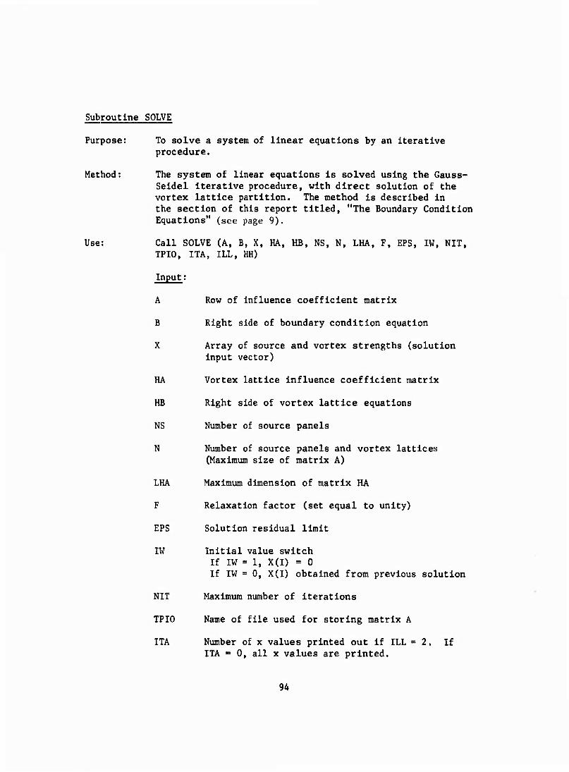
Subroutine SOLVE
Purpose: To solve a system of linear equations by an Iterative procedure.
Method: The system of linear equations Is solved using the Gauss- Seldel Iterative procedure, with direct solution of the vortex lattice partition. The method Is described In the section of this report titled, "The Boundary Condition Equations" (see page 9).
Use: Call SOLVE (A, B, X, HA, HB, NS, N, LHA, F, EPS, IW, NIT, TPIO, ITA, ILL, HH)
Input;
A Row of influence coefficient matrix
B Right side of boundary condition equation
X Array of source and vortex strengths (solution Input vector)
HA Vortex lattice Influence coefficient matrix
HB Right side of vortex lattice equations
NS Number of source panels
N Number of source panels and vortex lattices (Maximum size of matrix A)
LHA Maximum dimension of matrix HA
F Relaxation factor (set equal to unity)
EPS Solution residual limit
IW Initial value switch If IW = 1, X(I) = 0 If IW = 0, X(I) obtained from previous solution
NIT Maximum number of Iterations
TPIO Name of file used for storing matrix A
ITA Number of x values printed out if ILL =2. If ITA - 0, all x values are printed.
9A
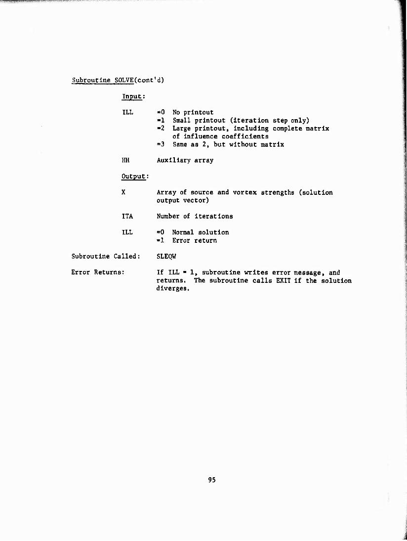
■rvwm m*"ti< ! II l< .^p-ITrr-f.LWPrTFTrT
Subroutine SOLVE(cont'd)
Input:
ILL
HH
Output;
X
ITA
ILL
Subroutine Called;
Error Returns:
■0 No printout ■1 Small printout (iteration step only) =2 Large printout, Including complete matrix
of Influence coefficients =3 Same as 2, but without matrix
Auxiliary array
Array of source and vortex strengths (solution output vector)
Number of Iterations
■0 Normal solution ■1 Error return
SLEQW
If ILL = 1, subroutine writes error message, and returns. The subroutine calls EXIT if the solution diverges.
95
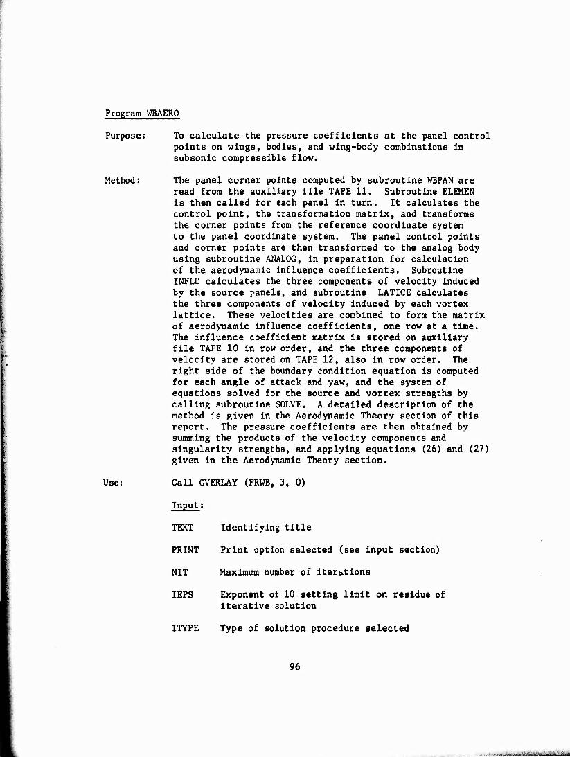
Program WBAERO
Purpose: To calculate the pressure coefficients at the panel control points on wings, bodies, and wing-body combinations in subsonic compressible flow.
Method: The panel corner points computed by subroutine WBPAN are read from the auxiliary file TAPE 11. Subroutine ELEMEN is then called for each panel in turn. It calculates the control point, the transformation matrix, and transforms the corner points from the reference coordinate system to the panel coordinate system. The panel control points and corner points are then transformed to the analog body using subroutine ANALOG, in preparation for calculation of the aerodynamic influence coefficients. Subroutine INFLU calculates the three components of velocity induced by the source panels, and subroutine LATICE calculates the three components of velocity induced by each vortex lattice. These velocities are combined to form the matrix of aerodynamic influence coefficients, one row at a time. The influence coefficient matrix is stored on auxiliary file TAPE 10 in row order, and the three components of velocity are stored on TAPE 12, also in row order. The right side of the boundary condition equation is computed for each angle of attack and yaw, and the system of equations solved for the source and vortex strengths by calling subroutine SOLVE. A detailed description of the method is given in the Aerodynamic Theory section of this report. The pressure coefficients are then obtained by summing the products of the velocity components and singularity strengths, and applying equations (26) and (27) given in the Aerodynamic Theory section.
Use: Call OVERLAY (FRWB, 3, 0)
Input;
TEXT Identifying title
PRINT Print option selected (see input section)
NIT Maximum number of iterttions
IEPS Exponent of 10 setting limit on residue of iterative solution
ITYPE Type of solution procedure selected
96
..-.. aäktää ; - ■-•■■'■j--"
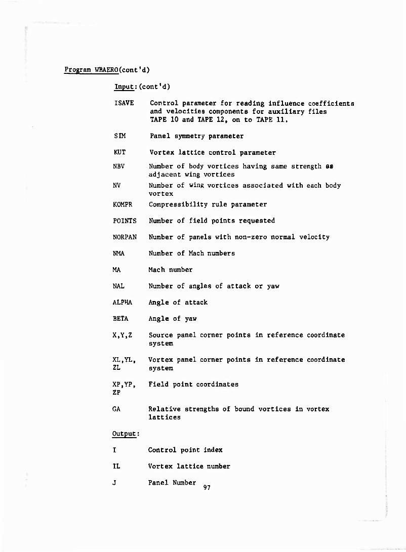
Program WBAERO(cont' d)
Input;(cont'd)
ISAVE Control parameter for reading Influence coefficients and velocities components for auxiliary files TAPE 10 and TAPE 12, on to TAPE 11.
SIM Panel symmetry parameter
KUT Vortex lattice control parameter
NBV Number of body vortices having same strength as adjacent wing vortices
NV Number of wing vortices associated with each body vortex
KOMPR Compressibility rule parameter
POINTS Number of field points requested
NORPAN Number of panels with non-zero normal velocity
NMA Number of Mach numbers
MA Mach number
NAL Number of angles of attack or yaw
ALPHA Angle of attack
BETA Angle of yaw
X,Y,Z Source panel corner points in reference coordinate system
XL.YL, Vortex panel corner points in reference coordinate ZL system
XP.YP, Field point coordinates ZP
GA Relative strengths of bound vortices in vortex lattices
Output;
I Control point index
XL Vortex lattice number
J Panel Number „ 97
Program WBAERO(cont'd)
Output;(cont'd)
LP Bound vortex number
BETA1 Prandtl-Glauert factor
NP Panel number at which non-zero normal specified
NORVEL Normal velocity
XC.YC, Panel control points In reference coordinate ZC.XCI, system YCI.ZCI
XE, YE Panel control points In reference coordinate system
A
F
T
VX,VY, VZ
AM
Panel transformation matrix
Panel area
Maximum diagonal of panel
Three components of Induced velocity In reference coordinate system
Component of velocity, normal to plane of panel (Influence coefficient)
RULE 1 Gothert's rule 1 selected
RULE 2 Gothert's rule 2 selected
VXUjVYU Three components of the free-stream velocity VZU vector
RS Right side of boundary condition equations
ILL Matrix solution Indicator
SIGMA Array of source and vortex strengths
VXR,VYR Resultant velocity component arrays VZR
98
■
Program WBAERO(cont'd)
Output;(cont'd)
V Magnitude of resultant velocity vector
CP
Subroutines Called;
Error Returns:
Pressure coefficient array
ELEMEN ANALOG INFLU LATIC SOLVE FORMOM EXIT
Program calls EXIT if:
1. MA > 1.0
2. J > 1500
3. LP > 40
4. IL > 35
5. ILL - 1
99
Program WBOLAY
Purpose: Main overlay for wing-body analysis program
Method: To call the primary overlay programs WBPAN and WBAERO
Use: OVERLAY (FRWB, 0, 0)
FRWB is overlay file name
Program Called:
OVERLAY (FRWB, 1, 0) (WBPAN)
OVERLAY (FRWB, 2, 0) (WBPLOT)
OVERLAY (FRWB, 3, 0) (WBAERO)
Subroutines Called: Exit
100
Program WBPAN
Purpose: To calculate panel subdivision for wings, bodies, or wing-body combinations.
Method: Several alternate paths are available In this subroutine depending on the values of the control parameters selected. Individual panel corner point arrays are read In If SINGPA • 1, body section data Is read In If CASE = 1 or 3, and wing section data Is read In If CASE > 2 or 3.
Four options are available for reading In the body section area. If OPT - 0, the y and z coordinates of the panel corner points are required. If OPT ■ 1, the preceding section comer points are used, and no additional data is read. If OPT > 2, the panel corner points are specified by the polar coordinates r and 6. For bodies of revolution having uniform panel spacing, OPT = 3 provides a simplified input option, and requires the input of only the radius and 9 increment for each section. If OPT ■ 0 or 2 have been selected, the x coordinate of the panel corner points may be shifted out of the plane of the section by an amount Ax to allow more freedom in paneling intersections. In all cases, the program calculates the x,y,z coordinates of the four panel corners In the reference coordinate system, and writes them on the auxiliary file TAPE 11 and the output file.
The wing section data is input as airfoil coordinate arrays. These arrays may be given in the reference coordinate system, or In terms of the local percent chord. If the latter option is selected, the chord length, twist angle, and twist center must be specified for each section. An arbitrary dihedral angle may also be specified for each section.
The Internal vortex lattice panels are located on the mean camber line of the wing section. The relative strength (GAMMA) array must be specified for each section. In addition, the y coordinate of panel corner points may be shifted out of the plane of the section by an amount Ay to allow more freedom in paneling wing tips and wing- body Intersections. In all cases, the program calculates the x,y,z coordinates of the four corners of the surface panels and vortex lattice panels in the reference coordinate system, and writes them on the auxiliary file TAPE 11 and the output file. For wing-body combinations (CASE ■ 3) additional vortex lattice panels may be specified inside the body. The input required is similar to that described above
101
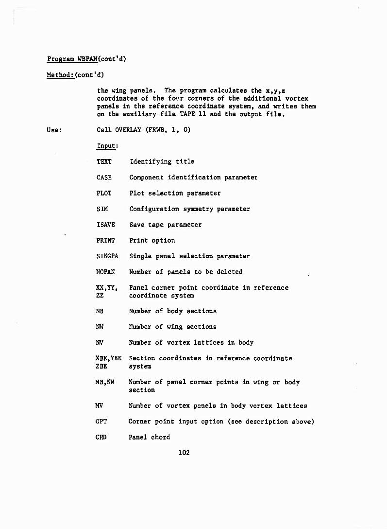
Program WBPAN(cont'd)
Method;(cont'd)
Use:
the wing panels. The program calculates the x,y,z coordinates of the four corners of the additional vortex panels In the reference coordinate system, and writes them on the auxiliary file TAPE 11 and the output file.
Call OVERLAY (FRWB, 1, 0)
Input;
TEXT Identifying title
CASE Component Identification parameter
PLOT Plot selection parameter
SIM Configuration symmetry parameter
ISAVE Save tape parameter
PRINT Print option
SINGPA Single panel selection parameter
NOPAN Number of panels to be deleted
XX,YY, Panel comer point coordinate in reference ZZ coordinate system
NB Number of body sections
NW Number of wing sections
NV Number of vortex lattices in body
XBE.YBE Section coordinates in reference coordinate ZBE system
MB,NW Number of panel corner points in wing or body section
MV Number of vortex panels in body vortex lattices
OPT Corner point input option (see description above)
CHD Panel chord
102
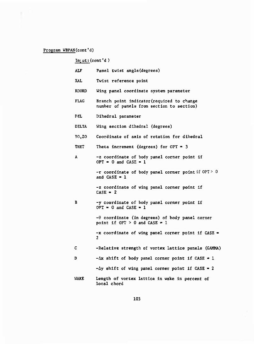
Program WBPAN(cont'd)
Ini ut; (cont'd )
ALF Panel twist angle(degrees)
Twist reference point
Wing panel coordinate system parameter
XAL
KOORD
FLAG Branch point indicator(required to change number of panels from section to section)
DEL Dihedral parameter
DELTA Wing section dihedral (degrees)
YO.ZO Coordinate of axis of rotation for dihedral
THET Theta increment (degrees) for OPT = 3
A -z coordinate of body panel corner point if OPT = 0 and CASE «1
-r coordinate of body panel corner point if OPT > 0 and CASE - 1
-z coordinate of wing panel corner point if CASE - 2
B -y coordinate of body panel corner point if OPT = 0 and CASE =1
-6 coordinate (in degrees) of body panel corner point if OPT > 0 and CASE - 1
-x coordinate of wing panel corner point if CASE ■ 2
C -Relative strength of vortex lattice panels (GAMMA)
D -Ax shift of body panel corner point if CASE - 1
-Ay shift of wing panel corner point if CASE - 2
WAKE Length of vortex lattice in wake in percent of local chord
103
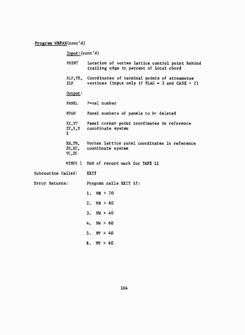
Program WBPAN(cont'd)
Input;(cont'd)
POINT Location of vortex lattice control point behind trailing edge in percent of local chord
XLP,YH, Coordinates of terminal points of streamwise vortices (input only if FLAG = 3 and CASE > 2)
Panel number
Panel numbers of panels to be deleted
ZLP
Output:
PANEL
NPAN
XX,YY Panel corner point coordinates in reference ZZ,X,Y coordinate system
XH.YH, ZH.XC, YC.ZC
Vortex lattice panel coordinates in reference coordinate system
Error Returns:
MINUS 1 End of record mark for TAPE 11
Subroutine Called: EXIT
Program calls EXIT if:
1. NB > 70
2. MB > 60
3. NW > 40
4. NW > 60
5. NV > 40
6. MV > 60
104
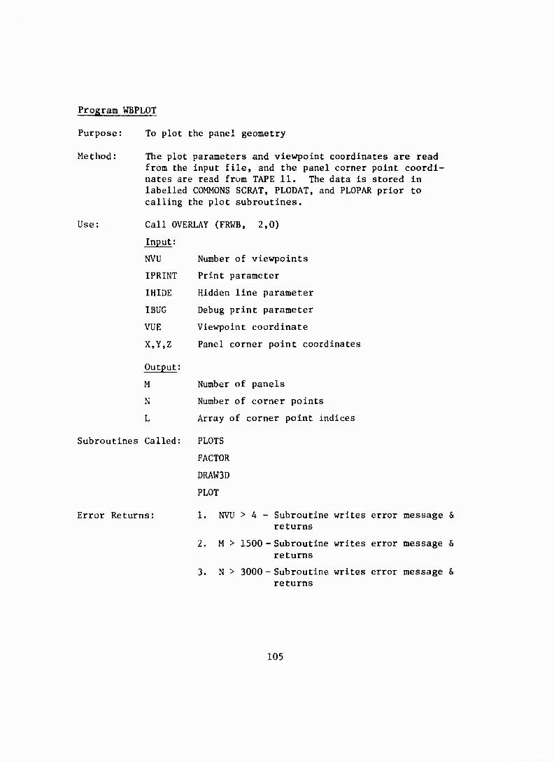
Program WBPLOT
Purpose: To plot the panel geometry
Method: The plot parameters and viewpoint coordinates are read from the input file, and the panel corner point coordi- nates are read from TAPE 11. The data is stored in labelled COMMONS SCRAT, PLODAT, and PLOPAR prior to calling the plot subroutines.
Use: Call OVERLAY (FRWB, 2,0)
Input:
NVU Number of viewpoints
IPRINT Print parameter
IHIDE Hidden line parameter
IBUG Debug print parameter
VUE Viewpoint coordinate
X,Y,Z Panel corner point coordinates
Output:
M Number of panels
N Number of corner points
L Array of corner point indices
Subroutines Called: PLOTS
FACTOR
DRAW3D
PLOT
Error Returns: 1. NVU > 4 - Subroutine writes error message & returns
2. M > 1500 - Subroutine writes error message & returns
3. N > 3000 - Subroutine writes error message & returns
105
APPENDIX III
SAMPLE INPUT
The input for a wing-body-tail configuration is given in this appendix. Figure 28 is a computer generated plot of the paneling used for this configuration. Panels are input for one side of the configuration only.
The body is an ogive cylinder with a blunt base, and is subdivided into 72 panels, including base panels. The wing has a truncated delta plat- form and a thickness/chord ratio of approximately 15 percent. It is subdivided into 69 panels. The vertical tail has a swept constant chord planform and the same airfoil section as the wing. It contains an additional 32 panels. The total nunber of source panels on the configu- ration is 168.
Vortex lattice panels are automatically included inside the wing, while the vortex lattices inside the vertical tail are input as body vortices. Eight vortex lattices are used in the wing, body, and vertical tall.
The sample input is chosen to illustrate some of the special features of the program. These features are described below:
1. Plot Option - The plot option is selected by setting PLOT = 1 on Card 2. The plot parameters are set on Cards 9 and 10.
2. Body Input - A simplified body input definition is obtained by setting OPT - 3 on Card 4B. This option only applies to bodies of revolution.
3. Wing and Tail Input - The wing input card set includes the vertical tall. The main wing uses the standard input option, while the vertical tail is defined in a horizontal plane and rotated into the vertical position using the dihedral option (DEL - 1 on Card 5B). Since the wing and tail have the same airfoil section, this data Is input only for the first wing section, and the remainder are defined by setting OPT » 1 on Card 5B. The vortex lattices are automatically calculated for the main wing, but omitted from the vertical tail by setting FLAG ■ 2. The vertical tall vortex lattices are input later as body vortices. The trailing vortices from the wing vortex lattice are extended 100 units into the wake using Card Set 7, and setting FLAG = 3 on Card 5B. The vortex lattice control points are defined by Card 6.
106
A. Body Vortices - A vortex lattice is input inside the body to provide a mechanism for carry-over of lift. The strengths and locations of the bound vortices in this lattice are chosen to match those of the adjacent wing vortices In this lattice, and the trailing vortex is extended into the wake such that it terminates at the same location as the Inboard wing trailing vortices.
Body vortices are also Input inside the vertical tail. The bound vortices are located in the plane of symmetry under the spanwise panel edges, and given a strength proportional to the airfoil local thickness distribution. The trailing vortices are extended 100 units Into the wake, using Card Set 8D-1. The vertical tail vortex lattice control panels axe defined by setting OPT « 2 on Card 8B, and reading in the control point coordinates on Card 8D-2 and 3. Finally, the symmetry option is Ignored for these vortex lattices by setting SIMOPT = 1 on Card SB. This suppresses the image vortex lattice system which in this case would exactly cancel the defined vortex lattice system in the vertical tail and result in a singular matrix being generated in the aerodynamic section of the program.
5. Field Point uption - The field point option is selected by setting POINTS ■ 16 on Card 16. The coordinates of the 16 field points follow on Card Set 16A.
6. Normal Velocity Option - The normal velocity option is selected by setting NORPAN = 8 on Card 16. The indices of the 8 points are identified on Card Set 16B. In this example, NORVEL ■ 0, so the normal component of the onset velocity is set equal to zero on the blunt base of the body.
107
n — (\j M I\J
•occecoeoi1^—^
a j a f* a x >r <r < c c 4.'4, a <^ « 4.'
o ä e o
r ~ c- i
-1 -3 J1 -VJ J -W O « — — .' O sj j — r ^ a j" a ty •
» f ^ ■« r-i — i u a r a
p * t* <i -a
O »C l/l IT tf*
■ c r U' c c- . c a.' c- — •— r c e c c c
c er c ^ c ^ — ^ *
• . • '- O C O C • ij T S CJOOCCOO fV »CfV-J f—O- — — — — — -"O • • •
108
a u a. f' a — J » o u
— «I ( I I I I I
c 3 o « o it
c-ccGCC-o««r c c rcc C" C" c c c c o c
J cr iT ir
c j- • • rv^ rv.rv.rvn.Afvrv'V'V
• c c ^ x- •J — — i
T c c a. o a • O (V 4 • • •
• — f\ -v,
■» ^ o o
■ x j ir iv ; -rxx^^r-jj-fi
109
APPENDIX IV
SAMPLE OUTPUT
The output for a wing-body-tall configuration Is given In this appendix. Only standard output Is given, since the print option PRINT = 0 was selected.
1. List of Input Data - The program lists all Input data.
2. Panel Corner Point Coordinates - The corner point coordinates of the body panels, wing panels, and vortex panels are listed.
3. Aerodynamic Parameters - Selected aerodynamic parameters are listed, together with the CPU time required to calculate the aerodynamic matrix and solve the system of equations.
4. Solution Parameters and Singularity Strengths - A list giving the residuals obtained after each step of the Iteration procedure Is printed, together with the final array of singularity strengths obtained, In order of panel number.
5. Velocity and Pressure Distribution - The three components of velocity, the magnitude of the velocity vector, and the pressure coefficient are tabulated for each panel, together with the location of the panel control point.
6. Total Coefficients - The axial, normal, and side forces, the moments about the three coordinate axes, the pitching moment about the reference point and the quarter chord of the MAC, the center of pressure, and the lift and drag coefficients are listed.
Items 4, 5, and 6 are repeated for each angle of attack or yaw selected.
110
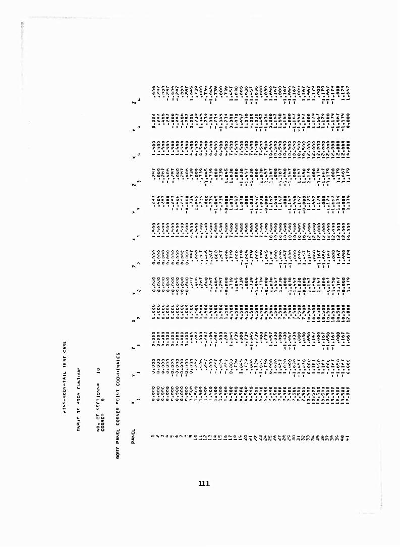
■
oic«,exoco'^^ncr'sT'^cr,x^©'riirnc^ircox^<ON*KO',*<'*»o
— i I^-IO-.-«*-I— — ^-o —— — l^ — ^-t . MM | ^ ^. .- o
cocccoccoecocoooooc©cooceoooooeo©co©coo©© ceccccccceccccoccccoccccccccecccccccccec© LriPirifirtrxifj'Xifj"i,-iririrxir.iririf'triririrtriifti/>irifirirco©ccc©cc
^.« — ■•«-.-•-,^4^^^^^^ptaK.f».f*.ftorw^.fs.oeo©coo©rvMi,Vj'\jf\(M'VJftJ'»
f«.e^j:f-cr-<(Tcc7'ifac(7'iroo©N-oec^-»,*-o^o^C!Nc»iOff^ffct>f^(y
K-r^cK^^oTif. ^ot^irtT' ©or* ©©©^OC^O^-ON o>»*offp*a ©ff^ao*
'V'4'\'OrVJ-»'\lCN.C^Of*-Or^©04 00©4'C©'-«—0 — >r — ©»-*«o—* — ©•• . — c -i — —
©cccccccoccc 9cc eoc©ce©c©eocc©ccec©©c©©o©c ccccccocccccccecccccceccocccccecccecc©ece it tr if * ififififiTtfiTJ'iftf iTtfirj'irififj'ififirifiririririru' ccccecccc
• ©oocooocr\ir\;rvjr\ir\)(\jr\ic\i^
cocooooc^c^-x^of*x»©diiro,©eir©oc'*-coef*-N©K©ri"Of1»'©^ cecccocca c« c i c a c^oi^^r. c^■^rcr■l^''cr^f1*c*l^*o«i^^■ c ©oc ec-oc^ erv ^ r\jo:\i ^f^ cr^ ©h- ©^ occc-* ccc^-»©'-*«-©-'* — cecc ccce
ooooo©co,^*^or»xr^ej'ir^o7'i/yo©',fc©©c',*oo^or*-ef»-o',^o(? oosoosarr sr srsx C''4■'no*^4^no'n.nT^'^J^(n©xlrfr©£lJ,^«C^■,*' CCCOCOOC<\i<frVCr\.sl{VCr»> O^-Or^o^COJCOO-J ©O— -i— © — ^.—C*-
ooceococ
OS»» O^OeOOOOOOOOÖOCOOOOOODO^OOOO 30©0000©0 oooc©o©osoc©oo©co©©o©ooo©©©©©©©oooo©ooee©
o c o o o o ' > — — — •-^ — * ,» 4- 4 4 44 j^N.^.^f^s-fwfta oo©©o©e©f\.
oco©^ooocr*•o*-*'fcO^.■^yoTl^'>©J^•o©©^•e©©e■l|*o^»o^•Oll•*^ Gooeocoo©x o x c « ex 4f>o'n^noniPnor)j-tr>or«')(rco4}Lna>otfc ©©■»COSOSJ XO-W 4'VC "VJS-* ©*>.©^©^ J0CC4OO3X — O— C— C— *
©©CCOCOC III — I «• I — — — ^— »«I rt mimt** -m mm
ooocC'-cc,^,tt©xCfi oa or^rp©ri^nor'>jiriociji',t©^,,u,4.C4,ir*o oooooooc^'\4'\.ci'\,4,N.C'^o^3'*'C'r^ec4cffe4,3©—c—c^^—©
aoooooooo I I I I o — I ) — I o -. -. * I -. -, — o — -■ — I — -•— ©
ooooooooc oc-c OOC C OOOCOOOC OCC000030DOOCCCO© COCCCOCCOCOCOO©00©aOCOC'©CCCCOOOOC©©C'OCOOO c■co©ccc:c■u~x^^lru■l^lPu, iriririri/'iru,t'"i/iiririru"iriririrtf>iruiiriririro ecocc ooc. ccc©e©c©i\
b. H c a 5 • o oo z u
a
c o a'
ill
y oa^yc^r-ff-c^r-ry-offf-^cTNtrcToooooooo
— ^— tf — C^X — C— >C — O— * — C — X— C — CCCCCCCO
*" ^■—— »-.-^- — «*- M M> M — MM '-OCOCOOOO
^ — e—x — c — x — c — x" — o — x- — o — * — eoccoooc
c -ccooeccoccoo coccooeooooccoooo cicccccccccece cccccccccccccoccc o^ccccccocc c ocoocc ecoeccococcoo
■t * ■* 4 4 »4XXXXXXXX
e > r^ j c (y ON r ^ o »^ o -« x
O^-X^O^X^O^X o — x—c — X — C — X
iy oc ^-^ctrKcoocoooo •^or^ x^-Cf^xococcooo — C— X — OMXOOCOCCCO
MI «• *> . '-—cceooooo
X-. s-^x^or^x*- o- x--c — x—e—x — c-
X'*- O"- X'-'O'^X^-OOOCOCOOO X — C — X — Ci — X— oooocoooo
— — O-H—-— — — -'0 3 0000000
C^CffCCCCCCCCCCOCCC c-cccocccccccccccc c::cccccocccrccccccc
-»-r-j^^-t-jxxixxxx A
ecc^ cooeoooo ccccoececoce ccccccccococ
cr-x^'C,*>x',-c^-x',,'C"r-^-f^cr^x^-cf,*-x^c^x^-cr'X c — x — C — X— C— X — O— x — c— X— O — X — c — x — o—x
">■ ''oa-^Toy^-y c: y ** y <Dy'*y<r>y,^yc'0'** : --c^c^-o^c^ -■* r-*- J'*' f^c^x^c^-x x--c—i* —o — x — c — a — o — x— e—x — c— x-
c? c o- f- T o
o^'rooocoraooccc c ooooooooooeocoooo O -3 00000 soocooo ooooooooooooooooo 'N.\'V'^'\'V'V^^-*-9-*^J-JXXXXi X
r? y i*- y cy^yeyi^y cy^yay^yoy^y & y r*- y oy o^x^o^-x^-of-xf^or- x'*-or^X'*-of*X)',-of*XNOf* 3 — X — O -« C — O — X— O — X — =>— X — 3- X — O— X— OM
*■. ^ C C ** O1 O OM 1 P* O »^ C P». O "" '
•^yc-y^ooy** if^Of^X^Cf^X'
1^: — e — x — o— x o-* ^' P» o r* x ^
iO— X— »— X —
C'.CCOC COOGOCCC oocce^ococ-^ooooooo O ^OCOCOCCTCCOCCCOCCOOCCCCOCOOCO c ■ OCCOCOCOOOOODCCCC c-ocoooocooc-o
.fV^^fVfVj^J^. T 4- J. X X J X X <■ J'
r ^ if, * * -9
U" o— fv i*i4 IF «0 f* «J Cf Ci-'ivri4ir^;r».(i'*/o^*c\i »LnLrj^riiP.rj>irj^,j^xx3xX'Oxix*X'0N'i»»N.
112
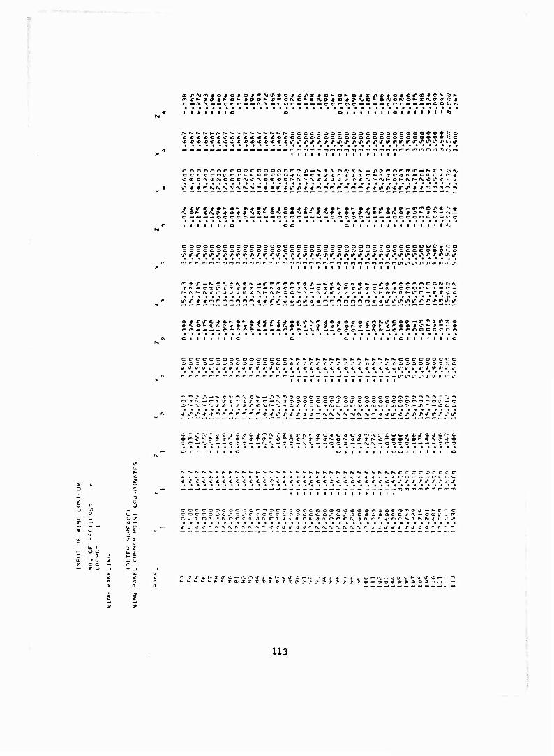
_rvrv.~ — cco — '-rx.rx. — coC'-'--- — cccoc»* — —»-ccc~>»-~*~eoc£e
• i i • i i i • i i • i i i e • i i i i t i «9
>.K-K.rwr*^.fw|wi«*f*^r*»fchhhfcf*.'SOCC C OOCOOOCOOOOCOCGCCCC;© J: «^«•C'C-CXX £X<£<C x^ccoocccoccoooooceocoooccccrc * c^c*^"*** ******. ^^ciriTiririri/'iririririru^iriririririrx'irjririrLiir
I I I I I I I I I I I I I I I I
c coooocoocccooocnff-ir — Pkoi(vo(\1'<ir*-^Lromofr-ff'ir»-"K*'^e^'\i cccccoiroirccccccojfv, — ca if C P^ c if - ■ c — f\jc^rv^-coir<'''-^
o ^-«»- — coccc^-^«— — CCO'C-*«—•— C OCOC^- — — — COOCOCCOCtC
1 1 1 I 1 1 1 e I I I I o
cooooooocoooocoooocoeooooooocccoocceoce^o zjoocoacciccooccoecccoocr cr socoooseooecoooc;©
"i m n m r") o n r
■jrv—oxiri''«£j'arc^f\jee^fV — ciir^r-Xircrc — n.4ccoc-cir — r= — r-A. '»-r\.«£u~^44Lr^',V'h-''VNecN'\f»-fv.xj- J-J s u t rs: r* ev r* & f* v r ** c e tp c
o — -- — — ccccc— — — — cc o — fvf\.——c c-O'- — fvtv^-ocoocccec-o
I I C I I I I I I
c e-c'ccooocooccooc
U J ÜU UUlTÜ U U L/iTi/JlTU
^h.K.^.fwoccooocec
4. >t >*. * X U U U U U U Ü i. IT
r»^ c* r" f i ■ r" r r^ f r-' r- r- . . — — -. — — --.-..-.,-.-,- — — iriririTJ" uu" 1 1 1 1 1 1 1 1 1 1 1 1 1 1 1 1
j rv. — c T U" X **• ^ ■»• 'X O X S
MO"" — J^Tfr10O3O0O'rooOOO0C,00000O0'3rj"'j0 x XT o — f\.-j ooococc-j- oir c ooocooooocoir'— c
x j-j-j-trir-r-r''^' ^jLrj-xx-j^''.,\i\V'v^fvxf^4Lrxinxxirxj"xif
or-x^^i^^N. er- 3 T &• c- o — M'x——c no — —'v
rxj-j-'nk'-4>o-* c^o^n^.LTioc^xj'X^o'"-
x^frx','y>-»^-oK^JTKX'^coAjof-x\iJj — c = — -^x — — CC C—— MM — coco — — — — oc
OlIIIIIIOOIIIIIII
XXXXXf^ cxxxxxxxxxxxx ■ C C C- c
occ-ooc o c er e 4 1 c;f\jf\ccC(\
-)ClOccocJcc:ooocoooococo^■c^J•-^,■(I■ f\ er n 4 -i 0 erv^n.oocfx. j^vca ^ccr-iM^nj^ u ■
^ i/ -j -j f* •\ a f\ rv rv r\ f Uj j-jrf\fv'\r\(vr\.'\r c y 4' Nf r 1/ -y
• c c c 2 U
> > J T ^ T- j^ j- r
113
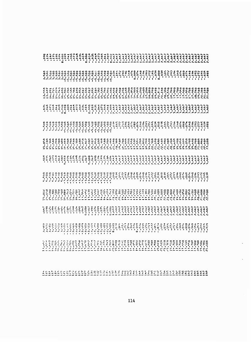
• I I I o • irvj(v<vojA.<vf\jAjf\j(\jr\injftjMOjftj
O I I I | I I I o I I I I I I I
irh- —j- ff^oc ccoecf\,of\.ccccooooc ooccecc occooooooocooooooeoooee irac^-fvjccccccir — c — ifocccccccocecircircocccoi:oce-ccou"cu"oecoco© if £ r\. *■ r\. r- ccr ^'rf — coccc—r^u^^ j ox'X onj-jfvoccrvj-jojoa -cc—"f^ir^O''fciririrf,*-fff»»irn<-ir
n^ ^^r'r-orLrxLrj,pLrj^ir^'ir/>j^iri/,.rj'X x i
C I I I t I I tv AJ rv.' rvftj(\(f\jr\jf\if\.,f\;rvf\irvn.'f\jr,r^'^r~nnr'*^<
cocoococcccoccocoeoeoooxira.'r^^c^c-jc^r'fv.irx oXirf\.f^ e40-»o-*nrv.irx©
trj,TLrirxirj,irirrirj>Lrirj,irxu"irxj'iro — rvj^j^ — oco — — ruAj--ooo'««njtV'---ooo^---fVf\j*-o©
i i i i i t i i i i i i i i
cccceeccccccccfvcrvececccc-cccccccccocccoceoeccocceecoccco j-ccccocccccccu" — c — LrcccccccocccircircccccceccoocctTCiTCCcocoo
— r- ,» K f < C c i\i o »•■■ ff IV ff ■» cjCTrs.a r^crvj-^: cc ccooccc—*- — *-cooc c — — — — c^ ■/
C I t I I I I (\ n.rs.ri (^^^(v^fVf\.f\.r\.(^.^^.t^r■r■ r- rr r-r'r'fr't i r" r- r f r
c>C'occc.ceccococooccoccoocTLrfV'^>jo^c^=)^'^fVirxcxj"'\.''co-JC^04r:(V'Lrx
U"1 u a J u j' j u ic u if uv ü j> j- a j- a tr- j- j- j j1 o c ^- tv f\j — — c o o — — rv r\. »• c o o — (\,' CM ^ — «r o o »- •-■ t\, rv — o
(J J LT J if J'' d~ ' 1 1 1 1 1 1 1 1 t 1 1 1 1
— xoooooojn. — on- tr^- ". i irxo — rv ^coooooo,poir*=oocooooooco©iroiroooooo o= — ^ir^jo^^'*-'V.i'trj-J^J,,'C''\.^'\j^'.0'-'^j^r«-T^TXx,^'T^-j,w— oxixo'Vi-T'Njooo'u^njox«
d'j'irirj"j'ifii/ir4*4 . r«- »w PW f^ '
C I I I I 1—<-i — — ^■ — —— ^• — — — — njf\jr\,ivrv rxjnjfvrvnjrv !V »V (V ft« f\j
tncc cececc©o©c©oc c-oec^c 03 cccc-cc^c^c-^ocrcooc-c ocoocr-3'' r ■S' r r J- x r s r s r s T\ s \r< 'S r .r s r r s s 00 ! <%; ^ *. -. O O C ^ — fV. X .
© I I I I I
C.3 if fV ** ^TCrfO^C^faiTT
e o—'vrv——ooo«- — ^^ — r.
I 1 1 1 1 1 1
v'.'r'iT^^-r^Xn.CfV.T^— jcff^ccoooccoccjoccoceococoocoococooooo •'V-J-J t\ ~ c- x S £ r i u x c—r\ J OO C- OCOCOJOJ" t v_OOOt;OC^OOC.OJ~OJ" oooooo • (Vfs-Kft.^-rvclT'-T^**« 4. fv »^ t\ r^ o o w o cf^J'^eco'\J^^.cx^t^^—r-a■^'a•',,«■l^l^l^^^c^^•l^^,"■-
■j a J j" J -1 -r ^-jufU'ico'Ta ■i st ^ 4 ■* J- «i-
j ji ^ r- 1 a- c — tv r^ t J* J r- a ^P r — iv- f*^ j 1 . (v- n j j- SL r- .1
114
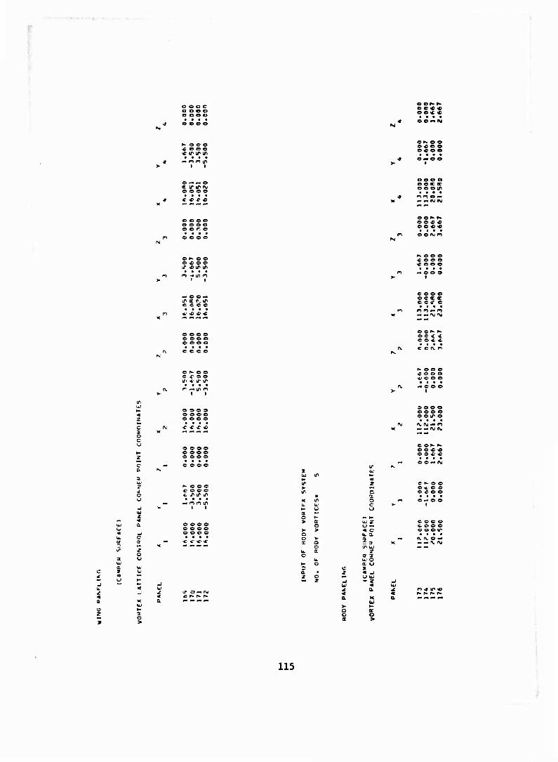
.
e e o e c o o o o o o Ü
O OK K
o e « «
N e c o <c e o e « IT tr tr • • • •
e IN. o e o 4} e o e « e o
o — « o c ir tr (M e o o e
o o o o e ec «■ o e o tn
m. *»t\J IM
o o o © o o o o o o r o
o p«. o o © -c © e IT * IT IT
K. c o e sC © © o -r © o ©
— © © — IT « r, in c e c c
c © © © © c a oc c c IT e
o o o o c © © o © o o o
O O P- K © c c * C © X *
c
o c u
O
© ^ © o C f o o U1 *• IT IT
o o o © o © © © o o © ©
o © © o © © © o © o o o • • • •
P" c o c x< o © c * iT 1/^ iT
J3 O O O « o o o .... — coo
1
o o o a o e o e o o IT e • . . . iv M — n - —M (V,
e or' »» e e <e « es««
X
o c
•- O © — Oj
c ^ o o o ^ o o o « o o
o o o o o o o o o o o o
0 — 1 c b. a n r a- i/i u.;
r o a U.' o a u x
coco c o o o C O O IT * • * •
1%. fv o — — — X l\I
1 o
o o a
at o
115
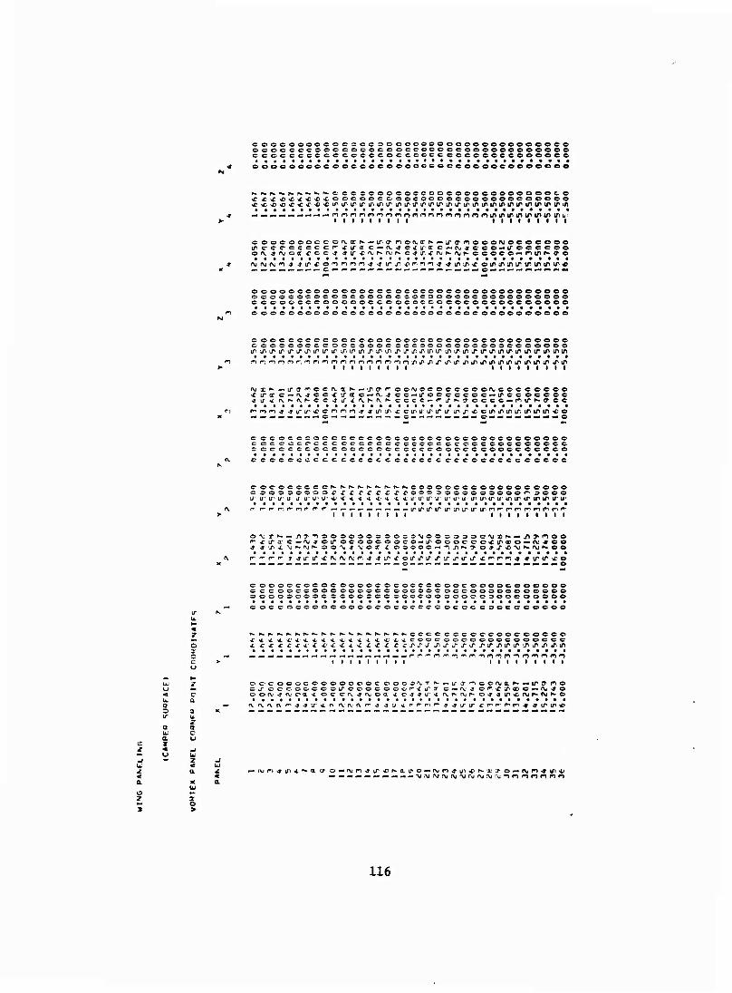
c C
coocooooooe^ocscoooooeooooooooooooöe oooooccooocoooceoccoooccoooeooooeoee c coccccccccccccoccoocc ccccceccoooece
oooooeoocooceocooooococcooeocoooeoeo
r^. r<b^*.p-.r>»^*-»-C CCCCCOCCsCCOCCOOOCOOCOOOOCO
**«*)**« »T^'CLPiriPiririfiirLnirtririririririrtriririPirirtriPiririii
i I I I i t i I I i t I I I I I I I
o ooc oooce orvarN^-u". a- nctvirN — ircnooofvocooooo irocc eccccr" icira c — rv« c>£irec c — fv^ccc^-irccccco of\-.jnjocr.ccc:-» -tifcnjh-ivK c-jx-rojr'(\jf-.ccoco—**>irKff'©
oeooooooooocooococoeooeoooooeooooooo C>CCO0OC0CO3C0OOOO£0C000OOCO0O00OO0e0 CCCOOCCCOOOOOCCOOCOCCOCOOOCCOOCOOOOO
cooooooooooooooooooooecooc-oooooooooe
cooccccoccccoooeroooococoooceoeooooee CCOOCCC^-C OCOOOOC CCC9OCOOOOO00CCCOOOO iri/iiririr,LrJiiPiriru^i/,iriirtni/iirirJ1J^triirLririririririri/l'iri/>irif'ini/t
t i i i i i i i i i i i • i • i i i
fvx*"- — ircT'^ocfvx'»' — ir(>focif>jocoeeceonüCocc©coo »circr e — rv^cc^: iroc c — fv^ ce^iroccccoc — irccoccoc >y \f *£ f\. K (V N c- C -Jir-t 'V.sar^ cccc — r-Lf^yoccc — nir^cycc
M — — — — — «»•C)'^— — -• — ->■ — — c^ — — — — — — — c— — — -•— — — —o
cceococoocccecoococooooocooocooooooo ccccrccc-ccccocc-ccccecccococccoccceocc cocccccoceooccc-cccccc-coocccoooccceee
c-cccccccceccccccccccccccccc-ccccccccc
c-oc-occccc^-f^f^f^f^f^r^r-r^eoooocecoooooceooo ccooz.oooor-crc^c^-rrooooooooo^ooo'-^ooo L/- u- u1 U" U 1/ IT U' U' 4J f 4. < < * «*. <. 4; IT IT IT IT U' tl1 IT IP IT tT U' IT IT IT IP IP IT IT r r^-r- r-, r-mr r-f — — — — — — — — — ^^l^l^L^,Lnl^l^l^l^r^r■r,r>f^»n^^rlr,
I i I t I t I I I I I I I I • I I I
""•cira^c-(M^oiroeooeooco — iroooceoxu^®o — fV)-»eo
— — — — — —— — — — — — — — — — — O — — — — — — — — -^M X — Mp.^MMO
coooeeoeocoooocoeociccooocoooocoooooo cccooccooooooocc&oooococcooooooeeoeo
OOCCOOOOOCOOOOCOOOC'CC'C OCCC coocccocoo
X' 4 Hi ^.X'^'A. -t X 4. 4,4. 4. 4- >t4;4.4.CCOCOOOOOOOCOOOOCC
I I I I t I I I I I I I I t I I I I
oocooocoooooooc OOCO^T ^—u"a -ncorvjaf^^-ir^no Ckroocoocooirooocoocr"1fi/
,a' c — iv-s cf^trnc*-(\j'*o oofV'-9njoax oc c-fvj'Tv.oa 4 c^y-jaw ivt^rvr- o^jir^rvjr-M^-o rv.rvf\f\r'^^ir4,rvivfV'(\r,j^u4',''^f''^-3-5i/ir4:'r"rr-r,ri^.»irir*
— nj n -» IT 4. '
ar o >
116
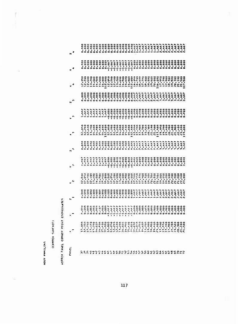
eocooooocooeoeoeec«<£C€)<CL>c«<o^>cc<e<£c<£<oc<o
leooocoooooeoococ* «njruftjftjMPuftjfyrw
oooooo cocp»f»^^r»K-r^^h> oooosoooooeoeooooe
coeoooooo^4)«c^«ctc<}coococooooooeoeeooeo
ooooooooo» • l i i I l i
•ooooooooeeeeeeeooo
cocooooooooooooocccccooooooooooooooe iroc c cc cccircececcGcuc-cc ocoecirceeooeee
ooooooooooooooeooo£x>C£<r'C^X,iC£4><0<fiC^ifi4>«
cooc oc cooooooocooO(\i^f^J^i^^J^^J(\Jf^J(^Jr•. nnnmnmnr»
r^Kh.p^K^r^p-r^-oocoooccoooooccoocooocoooee vC x x x> <c £ -rx-coooooc-c occccoocoooooooeooee ■c ■£> -c r<c<c XJXXOOOOOOOOOCOCOOCCOOOOOOOOOOC
oooooooooeoooooooosooeeeoeo t i i i i i i l i
occocccccooococcoccccecccocooooocoo© irccccoccoLTccccccccLrcccccccoireeeooeec
c©co©ccoooooococccKrfc^-^-f*-Kr*-^r-r*.N.N^K^f^^K
©ococc ccccooccec ©cxxxx < x ££ «cxx*cX'jC«f^,X)«c occeceecce.cccccccefv(Vf\.fVfvr\.fvft.f>.r-r-r. fr-r-r'nw
P^N ^ r- r- ccoooooecccooocc ©ooo©©ooooo C C ß C C ©00=:rSOOO©3©©0©OOÄ©©0000000 X^X*^ CCOCCCOCCCCO©CCC©©COO©CCOOC
:cc©e©o©©e©ooc
©©©000©©©0©0©0©00000©00©©09300e00000 ©ir ©©coo©©OLroo©©©cocxc ooc©©ooirooooooe
co©oeccoooocooooocN^r^r^^Kf*.p^^r*.f«.h-»».f».^p-r^N OC©©00©©OOOOC©OOOC<C<r'£'C>XC>C«C'C'C£«CC^C<C«4) oooos©oo©©c3e©co©©xxf'rxc<c<c«<c^>^)«c<c«^i« oocooc oc©o©occ©c©c< ■ fvftjtvrvojnjf^njnj
©cccceccCN.f^f*.^^.^rwr«.rvccccce©©e©c©©ooooo ccccec cccx'XX'C^.x 4.' ^xcoocccc ©©©oooooooo ©ooc©c^ooc-ricx*c-fxx=:ooc©ooceoocoooooo
©©oooc c o o * i i i i t
•cc©oo©©ooooooooooo
©©ooo©cooo©©ccoooocc©cc©occ©©oocoooo Cj^CC-COOOCOiT C©CO= COCJCCOCCCOClfCOOOOOO ©OA. ^a.'oa^c-cofVj^'V'ca x©con.-jrv.©(rxctrirr»>af»-Lr'*''-ir ivojivrvr- ^ ^u1 *f\,f\.'r\j(\,r-^ *ir^ ^ f * <f' a- a tr c ^
a
O o
117
i i l l i l i i l t i l l l l l
ctvfvrv eevfvrv.oaO'flccffff'flccjirr-irciiffirccfricco'r-O' OITP^IT oirf-iT cir^-ir cifr>.ificirr-ir o^<'^or^c^ocrjtox^doof,*ooof^oc^c>rocC'ro<r^acir-x,ff-©x*xoacrxoff^<r ox ox> oxoiPon^nooj-nonirnonirrno^i/i^o^ir^JON-^p* OP^^K OP»» *K OK *P*- OP-* -c f* 0"y>»%O'M-*i\J0f*0P*OP*OP*OO4'OOO^0O»--£i — O — *— O — ^—O — NC — C-.C — O-.^) — O-»^) —
I I I I o — I ©_. — -, I — — « c — — *- I
OOOOOOOOOOOOCOC ooooooocoe-ooooocooccooc oocooooooeeooe o soococoooocoocoo ooooooooooooooooooooooooooooooooooo c cooocccccoccoooc oeoooocoocococcooccooocooooocccoc oo iTir^iT'irtriPifif. iTiTir. ifif. iririririTiriririfu'u^iri/'iLfir. tfirirooccccccoccccocccoco MtMM^-t-MMrfHM^^m 4 >j -j -* j 4Krw^^.sKr-p*ocooooooojr\i(\jfur\j(\jf\jfVj-»* >» ^ s 4 4 $ < £ <«
^ar\iirc4ctr\jco.4,<rrvjcc4air\j%rc4a'rvtrc-9ar\.tic4X'r\.^c<fairvsrC'<Tar\.tcc>tforr\jcC4'K — — a.'ufNjrir'^^^trt/i^^^K.p-rxffO'a'ooo»- — ftjfVftjrin^^^jiir^c^^cf^p^oca'iffaeoo
— — «-■ — —-« — — •- — •- — -■ — •« — — '^-* — — — — — (\jf\i'\j
;\j o <\j nj tv QP A; At s o z CPSioi ff iT oifimkrioi/in(j' otynty otrnif»oi/if»-ir OITP^IOOITIP»' J1 OI/IP^I/IOI/IK r* OK i.- K 7K^xioct-«ac>ox-4ooo^oooK«ocofo« ox o r x x ox «x ox^x ox^xox« ao<xoxoacrior,4non'*r>0'^irfT)onLr*ocir^io*bpp,-Of^^"KOP*-iCP,fc©K<or-op*cr*'OP*-c fv onj ^IXC^^KOKOP* OKCOCO^OOO.»— o—sC — c — >f —0 — ^ — c — »f *-o<-c--o — * — e — c
1 1 1 1 t 1 1 1 1 1 1 1 1 1
f\*i\f\.cf\.f\.(vcff^acaoiacir',"iu'Cirriifoffr,ovecrr-{ycirKircifp^irc^rp»-ircirKtroirKj,c K<iKCNt£Kca<tfaca<9<iccKcccKCc«cc^c<fc>£C(r<(XciTifaca^(xca^aca^ac iroxcacxon4ner"4'^0'^ir''ionirno^in*o*ir*CK<>CKCf»-*r,^op^>üPfcOP»-*KOP*.%CP*o Tj^XO-Vj^^O^OKOKOf^OC^COO^OO— X) — c—£ — o—•c—o—^ — O-**'-©— c — o—■f — o
I I I c — I — I ©'
cc cc-ccoccc ccc cocc oe ceoc ecccccccocccocc-cocccoocccc-ooe COC C COCCCOCOCOCCCOOOCOCCCCCOCCCCOOCCCOCCCCOCCCOCCC cc c ccc ccccccccccocccoccccccccccircccccccocccccccccccccc iriri/'U'i/'u'U'irtfiriririririru'iriru'irLriru'i/'U'irifu'i/'ifiru'cccccecccccccccccccc — »- — ^- — -'^--•>j-*>»'*-*-t'»-a,KKKp^p^^KKcoccoccof\.nj'\ji\fv.A.f-j(v44-tf^4-J4j,^^%c*
cccrcccccp-ch-^Kcr-^ff cor ^tfea^ooc»^ cccK*fc^c*fc^C(rc.a:»cor cxxa ca^ (^OC-OCOSOX OT C XOI O'* O": ^^O^^n 0'nj^''C',"tfl^)C*X^ c>CirK OP«- rp«- OP*£K OP* * C CCCOC-CCMOf\J JMOfV^P*- OK OKOK CCOCJ- CCCJ — C--.£ — C — i— C — ■£— O — X — O— .£
OOOO oooo
cccoccccfvnjrvcfvrvfvca u-a ca tj-a ci/r-ucifru'cu-r'.ü-ccpf-a CUKUCJ'^U CU KJ C ccccccocK'fKCK^Kccc^irc-tt^aocp^cceN.ec^oic^O'tox^icx^acccx'Tc cccc-eocotroaciox©'^4'^c'*i-jf*ef^j"f^cr>irro-Cir^'C'rT^oKfKOK^*.oN.i;r*o eococ rocrv.-j'vofxj'vcp* or* OKCK CC J OOO^CC—J —C—^ — O — ^ — O-*C — O—X — ©
ooooccco l 1 l l
III© — l 1 1 1 1 1 1 t 1 1 7 1
a
C OCOO&OOOOOOC OOOO 000000000C90CC0OO000OOC0000OC0CCO00 o 3 ro oooccoooocooo ocoocc ooooocooooooooococooooorooocc c occccococcoccccc- coccococ-ocococc-c ©cccocecc-cc-oeoeoocc <r ccc cocciririririrj'a'Lrir iTkTira'irirj'./U' LrLriririfiririfj'iriru' iri/ cc-ccccccccoc oooocooc- 4 f t t S 3 f ooocooooM'\.'^;'V,,'\jfv,\'\j4 ^ 4 4
[\i «c o -tf a. rv 4; o 4 eü f\i c © ^ fli fv 'C' © 'V s rv «4 o^afu^c-joLfx^o^aiva. c-ja.'VjjO'jangytjcya r\.*j — ^■■(Xfvrr>r»4,4,iririir'rxp*Kp-.a:iJ7Too — — — •^ry^'nnj^irirr^X'K^KXxJ'T'^oo
OOO-J-C-C^O^P* OP-if-O^ -T x 01 » ocoocococa oa o a 01 j r* c- r # 1 =>OC-C.C DOS^A.'O'VJ J-VjO-ViOKOKO'
O-TP* OOOKoOOO^COX ox ooxxoxxx OCC t IT ox O p" tr p** © f"1 f^ ri o n ir »c 0 x w 4 OST^TK of*- ^LK or- 4. h CP* o*--* oooj oos*f — o-«lc — o«r—o-^x — o-«■r— o —
ocoooooo t
ccoc cc-occi\'Vfvc^ P\' fv e oocc rrccc^-CKOK^-^c cec c cccocx OT c 1 ~ 1 c COCCCC'OOC'XJ-J'VC'V J-VC
c x cxc"! CJ-'* ir©irfriLrc'C7''^cr oir^' CT OIOKIT cu- ^-irc-ir'-'ir JXCXjrcCKCCCKOCfCXCXCfCtCTCXXIOX-fT
■ 4 m c f 4 'T,cr'/'f*icmj^*icX'/,i)ex-iriOcr* x^r*- o"' x** c^ x^- cp-cKcr-cc-joco^cc— r — c — X-HC— x—o — x—c— c —
000000000 1 1 1 l
11c — I I I I I I I
c-ccc ocooooocc cocc oocccoccocoocccocoocococ-ooccocccc oc oooooooceoocooocc cococ cooooccoocccccccooeooooccccooc oococcoooooocccoc cc coooooooooooccoc ocococoooccoocooo ccocccccLrL^i/,i/"irirj"irLrLrij*j"Lr^ir^ü~XLnirLniririririf. j'iTiririr. irccoooccccccc-
OOOOOOOO-N— —i--'—^-^-^-» 4 4 4 4-34 J,«-KKKKf^NKCOOOCOOOfV"\J*\JlM'\J'\jr\j'\;4 ^ -J J
— j^? nK^z-jriK—j" Tnr*^j-> yriK^.TO' *^p*-*a"■c7, nN-rfiTT ^^ ^-j-ij-m'^ — ■/»Trnp*. —i/ij^r- — IT. ^ — r\j\i(\jnn J 4 4 S .r -C -C CKP-TTX^T OOO — —^Mrur^nj^^^1. 1/lf££KKd0^x7• T 00
118
— ooooooooi I I | I | I O I I I I I I I O I I I I I I
e ir ^- 1/ c- ir O QC ^ X O IT eh» c ^ oP* o — .c — o —
r^trcirr^u-cccccccccoccccoocccceccccecocecc-ceocc.cceccccocc ctrcoc-cioooooooo^.^-rw^fwh.iwh-r^p^^h-r'f^N-^oooooc'Cocoocoocooooooco fr-of» ^^ooooooooc^xtsC^i^^'f^'Cf«^'^^ 'foocscoeoooooooccooooooo ^> — o*-^—coooooooc ffi^^^-c *o>o***'C'C^1,J1tn^JiirLrknLririrLOin(/'iri/>iPj^LrirLftj^ifitr
i I I I I I I • t I i ooocooeoooooceooocooeooccoocooooeooooooooiT'-o — irooococoooooir^ oÄooococoocooeoooooooooGoocooooooooof^^i/: — »^.x'\iof\j(rr^-«iry"io^^ir — ^-ac'Nj occocooccccccccccocoooccociT cir coooccc^rvj—ex ir<r)xirs c — (\.^ c^(\ — oatr-r cccc>coccccccccccoccctfac(V^fvcoc(V'arvca^cr«-f^,K(v^ir-*^*»ir4.ar»-rvr'CN.fvr»'r\.iif4
(vc Cvi a fv^ o-«<rfV.<cc<farvcc>ysfv<«.-c<«aEnii<:o^er rv c o «r a nj^rc-^a i\>cc-^(x njhcc^a rv^e^arvj^- ©■»
c ceo — — »-—cooccc eo
iOiTf-oococooo^^- e — - xoxcxorxzoi'C'OOcsoooo-^.rira.'.Tor'-oro'O^ajhrhP-^oO'f.rj'iij-Yc r^ep^^r^cr*-* r^©r,*-^ocooococf\iOh-aru»y4 0NT(7,(V<r'**Of\joo'\*op*.xf\icr — o—x^ — c—^ — o—»c cccoc c ceo — « — —oooeo — •-^-•-COOO.-i — — — c
I I I ■ OOOOOOOOI 1 1 t I I I e 1 1 1 1 1 1 1 1 1 1 1 1 1 t
if^ircir^ircd-^irccccccccccccccccccoccccccccccccocccccceccccccccc a^acaxaofrxaoccccccccccccccccccccccccccccccccccccccccceccccc rk-^r-or-^r^cr^^f-ooocoocooocoococoooooeoocooooooooccooooooocooooo — i — o—X)—c— i — oeococoooj^xj*j^j'j>irj^j^X',PXj^ir^L/ixirj^Txxirjii/^i/^irt/. J^I^/,,J^J^J'. x. LTX'J^P
• ——— ocoocoooo^f^r^nnrnnr^rnr^r^nririnnnrinnnnfnoririnnnrinr^iririririririr 1 1 1 1 1 1 1 l 1 l l 1 1 1 l l l l l l l l l l l 1 l
oeeocccccccococcoccccccccir— c — irocccocoooeccir — c — ircoocccccoocu-
coocooccceoococcoeoc^^x—^ecfvcajcr^— XJ'^c>e'r'?ir—^or^jerverp*« — x^^oooooofv c occccc ec cccccccc c cc^r(\, — cair^fi LTT c — r\.4 cc-jrv — ea ^ -c r-^j-x e — f\i<recccctf — cecccccccccccccccccch-o.^(>.xi/,^j4ifx,r>.Ni\fh-c-ch-ar*-f\.i1cif^jcu'XPN^-rfcCr*-i/'' — cc
■■ -■ « »VJ ry rn ^ *»i 4 * J^ Ä • f\i fV »V fXi (\i fNJ f^ fV t\j (Vi fV
XJ'J:£'^,^'»-XX>5'TOO — ——'Vj'y'*>F*>*i*-»XJ^xcrr^,^^x)rT?'j-oo-« — —■y,\j*i'*i'^4 rv »\< <\ [\J ^ f\j f\j fV »M <\J r^ T\J n n n n D n r d r' r^> fi c n r1 n f*- D r; n r* r: r' n rs r1 4 -* ^ ^ ■* 4 4 ^ 4 ^ *
ifiOirf-irciTf^ir CLT^-ircir^ir cirr^c^^-e—4 — »^cf^ — ^ — or«- ^ocir -»a ^rvp- or»- (\,f*«a -JIT eoir— — tv -JO ffeo-Xffcaxtfcxxacffi<aca-rc^irifa-»or»cf,fcC^ffirLr4C(r-»rvfvrc*rcr-cr-fv.i\4tteo—Tf^iir KO'^CP*c^f^or^fN.c»*£N-of,*coi\'or>«.XMy4e^TnjT^o'NjO'^x:**y^^pN.cN.4T?,*-«^ooj,XN'-»'* — o— X — o—x— o—x — c—Xi— o—x oc— — — —o occ c — — — —coc — xr\i — —ooc— — -vtM— oeoceooc
1 1 1 < O I I I 1 1 1 1 o O I I I I I I
i/r»i/ ci/^-u cu ^irciTf-ircu^p^u ccccoccoceccccocccccc-ecccccccceoccocccec xX'XoxciroTxxoxxxoiXffcooeccecccococcocNr*s-^i>*.h«.fw^.^.fvfh.^N.r«-r»^cceoccc p»-X'r*.or^cr»-o'»-X'^-OP*-X',»-Cf*Cf*'OOocooooccoec©ocofxx'C»rxxx*X'*cxiXCC'Ccccec — x — c — x.— o—x — o—f—o—-f)—oj^irx u^ir. xj^iru^xiririrxxj^xx,*^c*^'cx.x,x:c*xx)**ir. j"irirx.rir
1 1 1 1 1 1 1 1 i rr r- r: r^ r" r, r" r" . r- r* r- r- r •
1 t 1 1 1 1 1 1 1 1 I I I 1 I • iT IT U" J- IT If tf
QOOOOOOOOOOOOOCOOOOOOOOOOOiT — C— tT 000 ooooococco soooooooooooooo 00000000000000000 0000*1^^—^XfVO^jX'»-- X'T-^oooooooooeooooooooooooo ooocccocceoocccocoooc^fv — cxirxf^xira c — fv-joocoocoir oiroooccocoecocir occcecceccccccccc cccc^rvh'ft.xir-»-*-*^ xiv^fv^cxa ci\4f\. ccoi\ 4i\ ox x 00 *■ \f r^ — o
4 * -9 * 1 ■* -jj^trxifl* 4 '*>'\j'\j'\j(\j'\ji\j'\jf ■» ■*irx)iririririj,*ir
« — — f\j.%j-lfnr, * tlTiT. J^XXN^r*XX>(T(T'0 r\i'vrvj'M'\j'\jf\jr\-'\,r\j
,\i'\j'\jr\Jf\jf\jf\jrvj'\j'\jf\jftjf\jn K. f». »w •▼ -r'»>i^.i-»l^v^_-— „ (\i (\, ■ ■
O-TX'MXC-fXrVj^. 0>}af\.Xc7-Ta.'r\d<4I,c3.Tti.ruxe'Tar\j4.C-T " tlTiT. J^XXN^r*XX>(T(>00 — — —OjfVi-', 'n
xi^xa-TX' (vx ojrirv.ic^arv'ijo-^a rv.x o <r a '\. m.* 4XiX|irxX'f,*r*^x.r(TtT'a' ec — — — «x^r-f^n* f^r". n^innnnnnnmr^n'nn^ •& -t *3 -* -s 4 s 4 44
xr ot)Xt)oxx r o x XTIOXXXIOXOX) ^MfMrno^o*" ornxjoj^ TX4f\jft.no'-iornon'\jrsj*x oo-tiri/ix ■*© x^" op" x ^or^x f*-c*f*- xi^o^-x^ c^onxf,-(7'cy,-»r*«oh- 4»r»'^x,*iri*^^0P'jN o^- 4<rirr»x*^iocrvof^a'''\(<^ X— o—x — o — x —o—x—o— x— e—o o—fyry — — 000 — — "VJ^ — 00 — f\j(\j — — 000 — — 'voj — o ooo — — —-NO
~ O I I I 1 1 1 I O I I I I I I O O I 1 I I I
oiT^- ipeiTN xeiTP-u1 otrr-ircirh-irocooooooeoceoeccccoocococoecocooooeooeo OXXT oxx ror xx ocxtcrxi's-N-,^^r»-^-p»h-^.f^^.K.^>.',«-^^*-,^*-^-t,^^f*.p».N-^»wp».*.r-'^^.ooooooc O^.X'fcer»-X',*0^-X^-Or,hX',»-Ch-X^XXXXXXXXXXXXXXXXX*XXXXXXXXXX«XXXCOeeOCC o—X — O — X— o— x — O—X — C — X — XXXXXXXXXXXXXXXXXXXXXXXXXXXXXXXXJ-irXiriTiTJ-
I • • I I I I I I I I I I I I I I I ooooooocc eoooccooocooeooooe ceoe ocoooooc ooe oeooccoooooeeoooir coc oeoocoooooeeoooooooooooc eoocoooococoeoooc ocoooooooca ir — f- X ooeocoeocoooeooooooooocooooir otr ooooeooooooo iroir 00000000-9 rv — ox ir ocoocecc-ceccoccccoooox xorvjjrxj ooc^Jt^vej xxo cfv.^fv.ocefv^ivoxx cc^rv^fViX'ir
4 4 4 ^r\if\i^r\irKir^yjr^4 4J^T44^,\lt\ir^f\if\i<\j'\ir^4 4\T><3C\riifi4 4^f^
119
or- — .ff — c^ *» ci/i— — f\i-ffO-»o-ic^r\.— — iroeoceooocc ooococccoc-cocooocoooooo
Off 90oT^Of\JOC>ffi4Pr^ ffn — O — n^F««ffOOf<C4)<C^«C^,>C'£^>C£ 'C*C£<CC^;<0'C^<)«CiC^4}*C4)XI>C4) OCe^" — '•— OOOOCOC>OCOOOCOOOOO\D<C«C«««iC«C«Ci<££-C<C<CX<C<C^^^C<iC«^C«C^«CiC«^
O I I I I I • '\j'\jnjf\jr\ji\iftj'\j'\jr\jf\ifMi\j«jf\jf>i
cec ecccerocecccccocccocccccir^a r^f\jr^ cr-rvNa ^ i/cccirsja ^f\.r-c^-fVh.flr -ff 1/ c c coc-occc'c^ccooooeocccoeoooeflT-fffXifV^or-cr»-. orirvfV.jeroff'fff\.'\jrier>o*T'onr\,<v^ec© coccrooooeoocooooc-oocooooomc^-^ff fff»-of^ ^T-^r- ^r-ion^f^^^ffr^oN- -^ff-t^N-^no
(iiii© i i i i i
c — i/iceocoooococ'CLroirocoooccooooooccoeocccocDoocoooooooccococ' c<i\tZN> — i/^'^oocooc'orviorvjooosoceoooooooooc'osoccooooooooooooooooo n^tro-o — rvjcoeoocir — c.-j-cococcccccooirou" coc occocococoiroirceooooo
mmi». n^fftr^ciririrxiriririririrtrirjiirj,>r(y'(ri',fc'f*x*x,*»Cf'-i
^4'»^ffj'-»-ff^^ff>rffLrJ,,irirLrir "
■ffaiV'fc-.-r J a-^c-ffaiv^ o^at.(\, i c-ffa-ai^c-ffo.'V'CC'.ff f\.<\jr^r^ff • j J^irx^X'r^^CCia'J i? O C O«- <-• ^Vl l\i (\I « <*> <* >*
ryi^j-Nj— — — — — ^ — — — — — f\|f\Jf\i
a. r\j sf* c 4- (T rv 4- IT IT 'f- <£! X K <l> ifi tT ^C <> i0 «o
0000C.C00C c o o c: ocoooooooooccococco C ffCff'Xj — — J" OOU- — — r«j^OffOffC fffM-
c — n^f^^-ffcoDCff^^-ffri — c^ri^^-x J <?*:<■£•£ -c^^^^^ii ^-'t*:c**^)C*x,**c*'£'*,4C*« ©eoococcooocc©ce€ee©ooecc<'jp*<,"C»£«c*>c*<'^c^i*£iCi£»ci1e<<fiiC'C\C€,**C<'«<'«<i
1 1 1 I'V'vivru'Njfvrvjfvnj'vrv.rvj'
CCCCCCCCCCCCCCCCCCCCCCCC c cif-J9t^-ft.^ef*A.h*a ccccccccccccccccccccccccca jfv.ixrc'' cr"cf(\ CCOCOCOCOOCOOCCOCOCOOOCCC'^'tf*>(r{J' ffP* Oh'-JU'Cr
ircccj'ff'XNrv^e^-fvKa -ffu1 ec .^a eiiff)\o.r-c^ercrf\fvjff c
, —o 33 — oj^——000 — — 'vrvj — oe
1 1 1 1 1 1 1 1 1 1 t 1 1 1 1 1 1 1 1 1 • 1 1 1 1
CJ-OoCCCOCCCCCCCClTCJ-COCC-COOOOCCCCC'CC'COCCCCCCrCOCCCC'OCCCOCC'C c-rvecoc-coocococc cfvc^cccecccc ©000c oooocrc-coococcocoooocooooo c — trccccccccccccir^-c-'ircccccccccceu'Ci/ccccccecccocciroircecccco
j- LT ^iTkTtrj'U" ^■^irirLrj-xiTLrj'iri/'irj'U'trj" — 03- T --—.- — — — — — — (Vf\.i\,fV(\fv rv — ^* — — —— — cvfvrvifvrv
— J"t7■'^•^ — ir^Tr-—lrcrr,^'—J^c^,*■*-—xfy^**-— .',ff''B''-iJ' ■ J-X^ii-'-'^^XtT' T7O0 — — — 'VjV'ni*
y ff ff ff ^ -T ^ ^j ff -ff ^ ^5 ^ U' U1 iJ */■ J u J i/^ a» 1/ J' IT J" !/■ J' J Ü U- ,' \J Ü J * <*. -t X' ^ ^ <■ -t ■ ff JI n /• c * • « 4. «L « « « «
C -JC-ff'V — — ITC ff^-C CT ,/ « r-a — ^c-ffirj""
^ooccooocoo — —
■ ff — r'cr — ^ — cr^- .ffcccc ccrcoc-occ-c ccccccccoecec-eceocc
-vj,7ffcff>Ajx'^o\JX,rr*£cr'C-c-f£'<c-cx'j;f'xr'Cr>cri)*%c*r1C'Cc*-c
I I t 1 '\if\j'\j-\j'\j'\i-\j'vj'\jM'\jr\iry-vjM(\j-n^-ifn-n*'r«in",,i'^'^'^'n'*i,nn
ccccoccocccccc-ccc-cccccccc-cc-u •3ar<-r\)t^cr*r\i*a ^u cccu ^a^tvr.cr^o.f^a^u c eccceccccccccccccccccoccccar fff\i\;'^o<,rc-',*"c''(\.n,-ffa cT-jrv'V^or-cricniVfv^x oec c-ocoeocoooccc cccc coocccr- ff^-jiy fff" er-- ff? ? ^x'^o^x^c? T-tr- of-^;*»K^n j^x^rj^iTXiTXi/'irj" if-iTiT.jnuntfitrtnu' J- J^ s s j^cc — fviv- — 00c — — HJ'VJ—coo— .■vrv——oc o — — ^rvi^-o
J"J■J,'l^l^l^L^,^^L^r"rr■n'r•ff,■. fi 1 1 1 1 1 1 1 1
> f* (*, f r~, r"< n f^1
J"OJ^000030CC:0C0Ckr--3 — iTr-SOOOOOOOOOCOOOOCOOO^COOC'COOOOOOOOOC vo^^oooooo-o^^ — ^-x-voMrr«*—ji^-^^ooooooo ^coooooooocs aocosooooooc o — c—u ccoccc^^ — cau -i^^tric — fv^ccooaooiroxooccocccooooeircirooooco
-n.n.^J■.^t^.^.^tnci^.^J, j^f-, ^nn-
4. o^a '\.i.o*a(\ja.oj ■t i.r LT x x x r*- ^ ^ x ac tr cr ffV'Jff-J-t-tff^-J^ffff
.^^X ^o — niv— — o^ff^T»»?© — ««V - — — — —f\jf\ji\jf\jf\jf\jnj — —— — — — — rvfV'VjfV
an.* offirvx o-ffa'vx o-iniv^. o-ja rvi^o-ja rv,^ o-ja.'Vjvtc ff cu TV •(.' © ^r a tw c © JOO — — — fvixnr^nff ffir>j~xc^^r*',fcxxa' j jc-o — — — ■\/f\jfnr,n^ ff'j^iTtrxxf»» ^iririrxru^triTJ'irirj' iriri/. Lrlf|J^t^l^l^t^XLnL^*xc1ü^cx^£)X)•c-c*x,xx,XJX■ J«
r re o - c- r —cococrcccc occ ccco
4- XX' 4* N(" X -i' < X X' X X' X) •*■ X X X X X 4 X X X xxrj:'XXX£i£!x>xxx)x>üxX'X'£'xrx>X)x>
■» c ■*■ — ?—• cr^ .j jr-c — ff — ^o^— J^-c^-» TC L-- 3 O rj o C '-o^-o t CLnl^-»ffJ^J■'-t-TO^■o^■^JI'^^^ffOf*■^^-'«-^-^^^-,
ff o-3cr'\jar'OfVf\.cr«-afvo'-ff cffi^ixa r^-of^ox xxxxxx o 000—— — — oo— — — — ooeoo— — — —oox" ex * CX) x
Olli I I I I c > • f\j(\(f\j(\jrv*nj(\ii\j(\j(\jfV(\j(\jojf>j*vi
;c<rocooooooc-ciC"occ'Ococococ,cc-ir-»,tf^fv^or'r\'«'a ffLroocir^xt*-f\.^-cf,*-fv^x-ffU'i© c-c c-oooooocc'oooc.ooooceooooc'Xff'fvnuno^ Df"oTf\,rv.j rorffrvjrvjno^omcnfNjry^x CCC■C■COCO(OC.■C'OC(^CC^OC;cOOOOOOO'r,X, '*•'7T■ff',,k0^--ffTfT•f,*■X'^C^^X>"^^'7,ff^■0',*■■ff»(^rfcX>'r,
j^xxj"Lrjiirx^ir/j"j'XirxipirxxirJ,»rii'Lr,co — r\j^ — --ooo — — fvf\, — ooc — (%,(%*- — coo — — rvrw — o ^rjf»i.*i«»>f»l»rii*lf^ *} fr) fr* f*- f*) .
I I I •^r^winr; -nnr"*!!
I l I I I I I t ■ (•! o
t I Olli I I I I I I I I I
■ C^-iTOCCOCCCOOCi/- — C—l/COCOOOOCOÖOOOCCOCOCOOOCOOOOOCCOOOOOOOC cfvar-—ire? rrno'ir--'fc-x fvc^ap"—i/ityr'cocococccoocoecocoooooooooooooooo rixirctc — f\j.ffff(v — cxiTX^xircrc — ^.-ffOocooooo'-noLroccooooooooooiroiroooooo 4-*u^xiVf*^K^rvjf^i\,XLrffffffirxrv^^.^ccxxerL^nuccor\,ffrvjoxxu~--r'irN-jKiririrf*>ffr,--inr^-«
rj'ni-in^ffffj^jiaiipff^ m^*innn^ 4tr/>xoyx»r»-xiXJX)X)Xxx»fc- ut)?— — oTD^r^f^f^r^^r^ec»©«» '-;■
/* > **l K -1« t/v er m P- — if» ^T1 "if*- —in? ri^.-j"»T rn^—^r^mr»- —LP7 n*«. —ITT '-i"- — ^rtrnp- —ir.7''^t* — LTtynr»- -^iry
4 ff t ff-ff * s •» .ff 44 4 4 4irirj^iriPiriririririftiririPiPiririf'inirtru,Lni/ tr'xxxx«cxxxxx-xjx)X>xxx)X>o
120
4 4(rr\j«o.*<c(^£e*ic(\j«o4<c(vt«e4a)(V4>e*a(\j
M — «xi <•) «t « t i* « * ^ ^ «T» oo — fv'vn'^^'kr/^«'©
-j 0^xr\.^0't<Kr>j^c4xrvj«e«aDfVi«e^ccrNJC04'S
#-i — — — rvfvjixrv;^ firing ^ * ^ ^ >riiriPir*'**
C o * at fv c o ■» c A. <: o^ xrvx c^x^sco-txrv-co^ — — — — 'vj'Vjfv.'fV'^r'r^r^^ j-^ .» ^iririTir*«*
j^j-mr» —ji^mr«. —jij i") r~ -■* \f\ (j- .■*) r* -■jitr'nr» -*iP(j^
*xfvxe*xf\i'fc*i,vxc^x'Vfio^x'\j*©^x'>J — •- « -i rv A. N a "^ r" /- »^ m ^ ^ ^-»iriririf -c * -c
~ ft * a o^irxotVLTf^of^^^.O'rvijxitr—^^x'-^n*
i V -V I» \I TJ rn w- .j-a r K —ira ff^ —IT» T— J XT — CX)X— ^ IT
/■ j^ ji r * c *
f^ cjcTfViro-jifvxcjxn^fc^xfViO^XfVCO-tfX
Xi*^^"^^. -*\-*i"^ ♦ .♦.♦ * n « « .ft o n n
^n — «^ -^ O- J- — •* -^ 7 X
— > m r- -i j" a ^
— r>. r\. n ^ ^ a* tf' * -n j JN .
*PI C-VLT^-CVJ^T^ rx.7— 4£X —f^xx o^iT — — — —'\,r\.,x\,au(«-if^^(^^4 ■*-*Lfirt/vJsi*^iC
xc*x vi-c »x'v*o-rx'\i*o J'D'v.'^otX'V.öo^ ~ X-^Orvu-^-T'vT^T — TXT— ^CT — ^LTrOOiT
— ^«-«•«■."Vfv.'Vt'V'nmn-i^ j 4 ^ S' a- J^ iT -o £> -c
-^ t 3 D^-vjxjcrwT »-; \jT'fox'\jrtox'ViX4
l\ X S 3 T r\i X 0 I X 'V ■i. 1 X 'V.' x c J T \ x 0 -j r cvj
> • >
J C .T ■T -\ •1 I 7 ■■» 4 1 r- ^ 1 O 1/' a C rv ir ■ - - - - \ 'V- -^ *- * " J j J J r r r J". X X) X >
„ r T ^ -^ ^ .r 7 * f^ _ r T - ^ _ -P 7 r* -w « r T m^. *- r T 'V .• h- T •J L 7 ■i 1 f- r 1 0 S f- O IV iT t- — — — — rv u \ -vj '' T ",
*■ -J > » ■J s J- r r XXX S
er -3 X \ •C c ■T a f\ i r J T Tv ■c cr ^ X ^X r 0 s X rv X e C J y a r CT -T 4. 'J i' X n ui X 0 n IT f^ 0 CV J! a — — — ~4
»NJ f\ (V -x n r- pr J ■j -J J if tr IT IT X X >0 s
7 r* ^ — ■.r 3 r—■ K. „ J" 7 w t^- „ ir -♦ r^i ^- « ^n T f" f^ — ir T ■S r- r '^ T * r — T ■* 7 — n 4 ■1 0 n T <l rr '\, ii> p- 0 n. ^ fc-
— — — — r\j ■\j ■u VI ■•1 n *1 ■-1 T J J » X r r ft X) XJ X > r* 7 .r ^ f- n -» if ~. ̂ - m a ■r — r* n 7- ir — ^ CJ ff if — ^ n rr — ^ ■*! p*l -T -J J- D 4. -v. t* 1 -> 7 ~ 3 — rv M "1 n T .r kT x a-
121
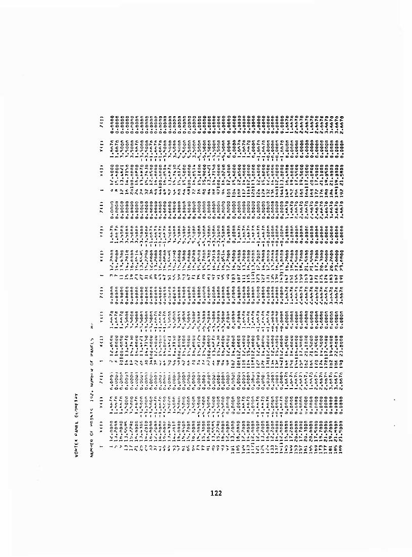
ocoooccoccococccoooooocoooooocooeoceccoooooeooeo oooocc eeccce ccccccococcc eoooocococcof*>Nr>'f*-h»^.rwfwr».Kffc.f* CoOOOOCCOOC'OOOOOOOOOOOOOOCOOOOOOOOOOfiC«C<r4><0<C^>4)««^l ooooc ocooococooeoooooocoe ooocooooooe«<^<£iC^)<c^)x«r4>«c
ooooooooocoooooocooooooooooooocoooooMMfXirvjrvjMrvjojf^nrtnj
cocccccccccccccccc c ccccc ccccoccccecocccccccccccc ^^ oocr- cos^^-c oc cococoooeooo^f^Ker^'^ooo'^ ocoeooooooeo <C'C000X>00££'^:0CC'2C<C>00000COOO£'C£OX,<£,000,£3C0000000e0e
-C— — CCC-'OOOOOOCOOOOO I I I I I I
OO^OOOOCOCO-l CCLT OO-t CO-xCCCC OOOOOOOOCdOOOOOOOOOCOOC OO-Xj^CC^-^OCO-^f^-nfVOC— CO-^jf. 03O0000CÄ00C00O0000O00000O oc-c — cdxjj-ccu-i-*—c-ctroo^: — cixcciroccoctrcoocoirooccooirecff-
« ^ r-. r- m — (
ocooooocoocoooccoooccccoeocoooooooeooooocooooooo
COOCCOOOCOCC COOOOOC-CCOOCCOOOOOCOOCCOfXiCiC £<0«<t<C)^*)C ccococeccoccceeoooc-cccec e cococococcox ^■>c%C<c <'<f<CtC<£^Cf
ccocooooooeccoooeoooooocoooooeoooooo-*--'^ '>jru'\j'Viivi*i'^n"^
cccccccccccc cc cccc cccccceccccc C CCCCCCCCCCOCCCCCC h-KccccccNr*Nr-cccccccccccccc^r-f»-r^^r«*ccceccocccccoccc i A, C- C C C C C ^ i' < -C OC CCCOOCCOaCCOf ■£ i A/ ■i ^ocooccoooocoooec ^■cr-n^-px/icricj-xj-r^j' r/,rj"riir = o*j;ccccLoocooooooooooooo
— —r^f', nnnr!.-« — -«—f r'j-j-j" Lr-tr U" ^nnr-oo—■— — -'-•-^oooooocooooooooo i I i i i i i t i i i i i i i i i i
CC-CCC-JiTOCCCCU-OOOCC ococc^ cocoocrczccccoocococcoccoo COC — C — t (TOCCCl ? CCCC CCC— C7— ocoooc occccccooc ccoccooo ccf. ccj i/ixcccatj- "xcccixj-crccirc-cjcoccoccccccccccttocccctc o-x ^o. cciffiwcfvcci/ n.cr-cccr--*fvcof\. a cr.ccrv.ttcn.ccft.au'P'irir^r-Cfvcc
*- — — — *.— .-— — ^ — ^——*. — — — ^^-——^.-.^ — —^ — ^- — — ---.^-—— — — ^-fviv—(V — nj(\.rv
ccccccoccccccc ccccccc ccccccccc ococcc cccccccc cccc CCC-CCCCCCCCC CCCCCCCC CCCCC C CCCCCCOCCCr^Kh-r^^N-fwNNNNI*- COCCCCOCCCCC COCC Z> O C r,OC>CCOCOOOCOC3COOfX£X>*X,^CCXiO^ COCC OCCOCOCCCOCiC O C OCCOCCCCCCCOCOCCCC«C«Ci*C'C**X c •c ^C
oooooooooa^oaooooöoo^ooooooooocssoö»-«- • M>j'VJM'V((\((*)'^r,>
ccoccccccccc ccccccccccecc c cccccccccc cccccccccccc r*-r.r>. coccccN-^rs. ccccccccccccccc^-N-»i'f*'^N.ccoocoecco©oe,oo ■£sC X CCOOCO-i f/ cccoooccoocooco^-^x x rxcccocoooocooooo ^<cxü^irrj*j-1riijD.rj"j'-r'j"Xirj'X-r/'.rooc,^x,xx*t^crooooocoocoooo
.*-—(-■ f r- r-, r1 r r-r-LTiTü" iTj^tT^'^ncc 'CCOCCCOCOOOOC cc
C O O O : c o c »*■ • IT C C Z . c e c x i
* C =• D r < i ^ C 3 c :
-^ c c e c f»* C 4 ^ <
^C-P OOCCO'TCCOSOO ccoocooocooooooeo
co'-cca -jciroccocu ccccc xccccctrocccc ' a ccj" o «c N c* c cc^xcccc^-cccccj ^■LTifiri/"'*'*©
■ -f & ** f € •*■ t^>rTCj^sr>^r>'C'^4'\jxd^r>ü'\i-t'\^ir'\i£ !-<——« C ■
.o-jti ^A c*a « — — 'VM-nr'in j 4 J" *r r r x
o -? t iv i o-ya'vxicja a «t tr ^ a fv «*■ c -3 a 'v x1 o *j a1 rv «t o
■r-?cccTrcrr-- r-rcc ^ c c 'rcc'2Ccc;=''rcrc5-.---o.-'CCcc-'"r*o.-*ccc'*'c
COCC000CC.CCC ccocccocooooccooococrooocsi?^ C4.4"«rtf><£<f4,-47« OOOOCfOOOOOOOOO 3000003 pOOCCOOOOOÄO'TJOOiXi^C^^X) £ £• £ G £l £
coccccoococoooocccoooooooococoocccco — «-^-r^fv..— ftjnj^nrifVi
fCC CCC CCCC CCCC COCC CCCOCCOCOOOCCOCCCCQOOCOC-OOOOCO ■^ *- «v OC*»- COC^^C^-C cr-C'50CCOOCC-C)S''*-'*-0^-^-f*-OC"*'OCCCOCOOC©CC CirX" OCfCCCX fCCOCCCCCCOCOCCCCX'X'C f-r ccc^ccoeccccocoo
■rx x J-J- -tj" r-x £ IJ~J" rxxxirxxj^irx/iccofiox 4 -coc-cooccccoooooo
-. — ^.-^f—'^t-'r- — — "-^i—ni/ij-f^xj- ri'^r'ircoo — — c— — —oc— cccc 3occoooo I I I I t I I I I I I I I t I t I I
ccoa OCCOCCCC-COCCCtSCOlTOCCCOCOCCOCCOCOCOOCCOOOCO© cccccty-oc— cccco—cooccocaaocccocooocooooccoocscoooöo eooiTfvo-iooocc'^cc.roocccirrN.cocccoccccooccooooceoooco crvC)Xfvc-j'\)C'\ac j 'vccr^oc',rCirfVicc'VC(Vxccf\.c'\.icc.'\jCh-'"cirffciPfxjIiri
\j -n C -1 .p X * ü^j^-c^ 4rx,j^*j'Lnc,'"ii/i^)r\jrn*o'v^.'\j.'\j',n-c'\j-*'\j^t
122
- —r'ji^ecc — r»-**»«
j —(-jvCsCao — r'r-tfKBD
^ IT-»— —f,*^-^'n(^ff1<?flOir
j — „ r- u ^acr—r-^irca
*- iv c\. r- r- j- U' 1/ * * f*-
^ 'VJXr£'-»-»OCT^Xryf\|0 _j — — '•'i^.tacry — —r^i ir-ox»
—*f\j f\,r^m-j U' ^T ■*■ ^i ^- ct
> ■» f\iXX*-»>»OO^X^(\jfUX >
M ■• ^4 -N MIM fM K > ——————— Z
rv, —NKf-rir^ffffifirir——r* c -j ——nj^aao — rni^i>(ra a
X
— — ^ —— — >
123
g a i e 2
I
o I- 1/1 »n C
>
u o -I
c 7
tr
u- a a
-r ^ - j u D - 1 3 u a w _i it o o o o 4 z > Z e> o e o
c U II C K < <\i -• o s 2 e « ■o <c
a a IT ^- J > IT o i * o o • •
A.' hk Z = I o X ec « X a « ■D « z ^ C C üi
a e> IT U.'
i a w II M n n o ii am a
or c _l>- o u UJ w lu a z u. r- Z z X z z
X a >• -DO »- ir u. K u »- t~ — 1-
124
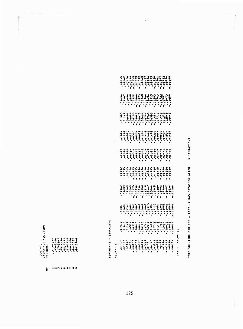
— — coooo*-— — f\jortO'-tro oocoocooocooeeeoe
i i i I
— — oooecriofVi — — K—one coooooooooooooooo
I I I I I
—. — oocoonjo^o — ^^-tfy© eooooeooeeoooeoeo
i i i ■ i
o- 4 ts* wm o **> f* K f^^a o^no.1 OJIT
^ — c eccc^-»-^^-cr^ef\.—p- cc ccccoc ccccccocc
I I I I I I I z o
f^^-x ^-r^ — (vxc — u- a i/> — x o aafv — OA.—<^ c -x f- — IT *i a <ir
— —■co-cccc—r- — — cvofrc — ccccccccccececccc
a
I « I
»<£ ire — n«.j r^^-Cif^r^aiPfV; " — ccccc — or cfv»* — ir — c occccccc occcocoee
i i i i i i c UJ
— — — OCOO^-^-fVO^O — lT — — o occoeooocooooeooce
O
I I I t I
o-(T ^ a o st *■ <f vc — irr^iraa.'C^rc
-. — — oc-ccc f\.*- — **—or'Ofv.o ocooooooooooooooeo
i i i i
«. — — cocoor.o — ^^-p-fMono 0 = 0000000000000003
I I I I I I
-j o .
f^o-jr^^irx^.»
^i/irjyr^ox'^o C T IT — -*©-»'\.—
(7- a — c ooooe
if f; (\, < rvo •/»->• 9" c 'V •■ ^ m ^ n 4 3«
— —^-»-COCCC^- — OfCfV) — — ÜTO — cc ^oc-c coecoce©©©©©
1 o •—1
IT
I I I I I
z
125
a — — — — — —^•—crccccce crcc-c-ceoocccoec-cocooeooooccc'-oc^-occc' u • • •••• • t
I I I I I I I I I I • I I I I ■ I I I I I • I • I I I I I I I I • I
iry>/ij'kr/,/'/tnj'\;f\jAifV('\j(\jfV—-- — — — — — ^J>J 4 £ ■£> -t ♦JiiTToNrvoff'ir^*—KN — * — «•* — —— — — ——— ^-^-P-K^f^«*.^—^— -•-. — «-.(\,rW'V;f\il\Jf\if\jlN(.\lC— 'VIV— 0%'\i^ti/l(\i(Mir^'\*0(V 7aj7><^90'9cr7^9^ff9'9cooccocoococ>oooeooeoecoocoeoeoceoo
c« xcoixOh-^^N^r^K^—^ ^—-.^4—irft.n.iTirft.A.j'—————— — —c^^oc^^o©-» ^ ft.oci^f\.ccrv — ©o— — oo— — cc^- — ce — ococoooooeooooecoccocooooo
i t i i fill till i l i i i l i i i l l i f i
a-cia.c;cxp>'^-r»-p*-r'f*'r*.f*.^r— — ^■^—-.^rviirirrvfXiTirtvocoooooo — — — — *« — w< — ^»i-« O^A-OO VJVOO- — OO«— OO — — OO — — 00000000000 0000000000000000
I I I I I I I I I I I I I I I I lift
2 c c — o
r> o a c
iiffaxffXXj^4^4^4^f^'*'"f'^'^'^'*rif\jf\j^^i\1i\fr'irffc^^e-ffi/'--i/»cNf>-oir--wo
la x 'xx x xa j" LTLTU' tf f W IT oococcccnaf^'viN.fvnjfVjfv.ixo—f\jf\j—ofviNj-tfiTfX.iviP-^ftiO^ itraaaxxacrco'ao'O'cracreocooocccoccocccooooocooooooooooo
irxirtTü' J" if if xa x x xxxx^'*)'*''» '»nf^* x^ c-c* c*-rr f^r-rrn^rfc-r". f\1,^-r*.^■^K^►f\(fv^■ —<**.^—r-^-^-n. ocA.rvcc l^,L^"^rM'L^l^'^''l^trooc^t^coa<■^^r>*^r^^^c■ClfV<\,«t|«c^v, fv *«c*v *T ?■ -><»c?■J'•nJ^^^-L^J,,^*^--P',* ■* >»^K4 *^f>.X^'VfVJ"XV — XX--—XX— njXX'NJfUXXMfVX
i i i i ^ i i
o« ^/■J-l^1r^fy*l^i^XIXXIXXx'^4^'l,'. '^4•»^^'«£>fil*^c^^^-^r,f»^.r•. np»-^.f\.rviN.h»(\jf\jN^r\j I fK.«M(^^^«fwor\jf\:oo^r»jo^d^iP'', rii^i/inoa^ooff-ff-cn^j^rori^^infVj^^fljf^c^NfVjiO
j^i j-—— r/* — —j'f^{ya,^^?^^^>f*>'*''Ci>'»"r^-ro^-r^oe^'^oCLri-r'1c^,y,Lp*ynji\i»^f\)f\j(>7f\j X-t J-^TT". *T'^Lrj^'^-*J^J'',^J,',*fc'-t t,^,*--JJ"'U'\JJ^/irviru^D — — -Ct—-«Xr'\jryXX'\J'\jXX'VJ ^< crv-xcC'V'Vcrv ij. fxrvxa rv^c'C'^^cONyu"r-~ijirr'mL''j^4^irU"-»-JU1ir'»-»irtr4«»ir(r*
I I I I I I
C C z c < o
OCSOOOOOf.C'C.fO'C'O.C-— - sooe^ocooooc ooooo^ C30000C»^'00't>OO^or»(\)!' cooccooc'fvA.f\.r«,n,'"v A. r\.x
^ -• w« »^ ^ wi |/< J^ tA tfl Lfl LA l/V rf^ ■» -»>J •* f -* ■» .^OOOOOOOOOO ■J-IJ*4jriCOCCOCO'\i(\'f\jrvr\;A-'\jr\.0000©00000 "U^. fV1 MM 'V-^— — — « — ———— — ——-- — — oooooooooo
xar r. ffr. r- r^r-mif iniririr ifLTiroooooocooo cccccc.ocr^.rvivMfv.MMfvjcr cccccooccor occo(\.f\,rv MivrvfVf^ooooocoooo
.^—^'nmr^-n^f^^r'^- x £ ^c ■t -r £ -c 9 a j-^a-o^a-—— — — — — — — "nnn^rinnnmif»
• TV »») ^ sr * ^ «■ i» o — rxf^-rif^ r* xo-c—rvri^uj h» acr o^-rvn^tr. C^XLTC — rvnjtr^iNXffO
126
ifp-rtir^c-ff — cocc — Ä c cceecectrcaiv.Ntva a — ^c^—ffeiriro<c^-'fCC|'*C«r\.r* a ccceeeceocccoccoooococ—e — fnfVft.or'^ofVfv.ri — o*-»-op-nf\jNe^r,©i\(rw
i l i i i i i l i l l f i l i i i i l i i i i l i i t i l • • l i l i i l i l l l
coocooceccoooocooeoooo? ©c — — — ©r^r*- oc*- — ©»a aff o^-^-coNh-o»«*-
♦ ^o^i/icyn^)^ao,**'^^fyiroor»-'\iN-T',,»«--**ff-^^^flDC4>'*N.ocN.©f|w^1co'C*tA'*»1* ©r-r-c^tfir — —-eo — — u'irf»-<r-r»-<r-u"^iCf^rfff^r'^irir^r,*-ir*r4"'f*irr^airir^f*-*r>ccn
i l l I i l l l l l l i I I l l i I l I I l
-©^©•fxr1—i\ieo©©'\i^-rvf\j.-»aar©(\dr,'vc^ — — irnff ^ ^^^«^a^^ffir — f^iT^H^nir**
«»»*^ ^rv^ o*\ir\j©<»fVfle,-r'w©eiviP i^©^^» *—t" ^ ^« ^©©©^^©ooirxa-fK***» — o© — ——«©coo©©— ooocooco — — — .y m ** *B «^ *©rn^— — —^-•^^-*n©«f,fc«*-«r) oo©©c©oc ©oo©©oocoo©oo©©ooo©©onnoo ©©©©©©©©eeoornnooe
I I I i I i I i I I I I I I I I III! I I I I I I
•f^CsffVK©^» fVi\['3''*,co©co©o©C!T e^x — ^—'^rir'a^a-a u % ^x^x-jn-fr^iff, u> — *<»-»«cf\.if-ffo*^o,o,^o,-»c©eoooo©'vri©fVjnwr)^c — ©i\.ir©f*'OKf*-©r»-©ir(Vi© — *KnM kr«'flCirc',naari4^r^x»©©eo©o©oi/o,^-«©h'a'«coco,«ir^oK''nKONifecff'«iC»^o (\i-.«f\jf\.on©©©ocofn©oo©ooco-.®xirf\j*irir^ J IT — <»x x*- — xaj—in-»'*irir'ö»\j ccccc©©©©©©©©©©©©©©©©©??© — — ©criThrer©——ccrcrcr9'©-<~'0(7'irin(re —
7 C C - o >- a Z> o a o M • a e ^ IT.
O « I
u- a. » J 3 " if tr u a a
o o e « e
^cvfv^r^^rvNf^fvcv^f^fNj-- lf^-■*-■»l^-■l^^■1»r^©l^cJ''r>f^(^l^©^,^. ■tff^ifiP^-'jnoirff^ri^ir© rv * < A; i\ <«t(\ifu«c(^fVtf. ■«Ott ^r sj a. a «a.«rvp>-C7,f\.MKr^wrvcr^rV'<9a x«f\jf*-afV'—^r*-»-^ tr (rrvfv.o-oft.f\.fffffv.A,(r^rvff<vfvxfffv.(vair«f\.ir<v,o,(Tce»(y'\.irfv^ifir'**\.ir'v,ffO'ccao'fvj xfvj'vxx'NjxxT'V'v.xx'V «CT-T1 -i«^?1 *-«XT'*,©'*)X'^nx *iof^xx— — xx'^onxrfrx'^© ir*-*irj''>»'*irir-*'*inir-»ffi»^'^ff(^'^'^i>co^-f\j'\.i^-o©oo«fV(r\(-N©coc«rjftj«o©©0"-fvj
i i — i i i i i i i i t i i i i t
O T
|4J < > a
x(\j,\t<r«rur\iCCf\.r\i'£<crMX«4xX'«<fxce©©©©oe©coc©©©©©o©©e©©o©eee ftj tf1 O Ai Aj 3» » <v IV Jl» O 'XifVj^ t\ixxfMfvx<t rv.'r^Nf»»N.r»»^p^r^f^^»^p*»^f^N-N-f^^N.N.r^f^fi*f»'^r»-h-i»» f\jXX'\J'\jXX^A-XXf>j(VX»'-»-» yj-« IT— -•-* — -<«'^— — — -^-*-«'- — — — — -* — ——-•-< — »-••^ «irir-* -9 \i it * ■& if J* -a «ir^ffO" '^mo,(T'frij'j'i^ii~u^iririiririf>iriririrtririririririnj,iririririrtP — i «p* »M | M «» i M. «* i iiiif\.fv)(\.'\;(\jr\i(\.fV(\f\fvnjft.(\.'CV'fV(\.(vrv;(\,cvrs.f\.(Viv<Vjiva
It i I l I I l I I I I I I l I
©©o©©©o©©©oooo©oo©oooQor>irxo7'OXx © o oxirnx>*o<^irxoa'ox«©^© ©©©©©©©©©©©©©©©©©©©©©©•M^rva1 irfn^^a-^r^irarvic—"«r^cDirn-ffcrfr^nir ©oooo©©o©o©©3©ooco©©©onr\jjiKOfnNnf*tN-fn©^Lpf\jr>fin'\jiriN-onNP)**»r*no ©o©oo©©o©©©©eo©©o&©©©onn^a'*i-"«oxax'^r9-fr)r>r>ntc<rnMXCx^Mr) oocc©©©©o©©o©© c©oo©oo©xn«cffn»f^ <i> •£ K o^na ^nacxM^^nfff^ x * N- ^ r>
— tr4riririririririr*»r*»c«*«**«p*NNr*f*r-Kr»f^Nttxx«xxocxxa,<7'ffaa»a(7,»»a©
127
I I I I I I I I I I I I I I I I I I * I I I I I I I I I I I I I
f\jn — ^ \ja-n4 o £ fv^ox^1 4 -- — r — -^* — — 4 r>xoi/if\i*o4 r'icy'\*-^jirnir4 xi« — -* — t 4inH
— coajff——^■ — oxr^c — ^- — — ffff^a— — — — cf^xo — —— — ©•»aoe^-oca««'»©©^©
'*><rctr^(\(04x ^ jooxoiviiK.xarx*** c ftj fn i*» * •* a* 4X 4 e iv « n c o — «fo — 44 — o-c—o 4 — 4Tf\j — "^^ x ox^—IT-C x^oo- — «(To^-x «T oN-rox'»-wi — (\jo-*x,xi>ÄX(yinif»<y«*x)S) ^ ^r'r<'<«c p-^ca ^-»-if—fv—r^^ ^-ir^ tfirr- »fr-—(\—ir^-^Xirr' 4 ^r^cft r"x 4Gxae4<Efirfv 0.4^x1^4(^4^ —cxco' 4'V,4ü"xaa 4'V4acxo — ff4iV'4iricr'i/"—a x — cr-r-o^-cct«-
h^ o<——ce — — c — ^.4 4^4^ —c — —cc^ — c^-f\.'4n4 jo^-c—^-coctrc-oo — r^rr — eooo
till 1 l 1 l 1 1 l l l l 1 1 l l 1 l l l 1
— o1f\j'\fV^fft—irf^incj'O — ocxc4O''XN4ca'CJ''^r-im^*r^s0J44f\j — «f\j444* ri^ — ^1 — f*.c — T—^Kj^^x^x^J'TX/i^ij^^»*- — T—01^ — x^-x;cyr\jnoxx>x)xomfviO' nfVO^iVC 4 —-^^^^4 — ^ X X'^J'V'N.'J'^XT i^ — ^-f)i\iO(\j-« 40f\.'J'Cl/>— 44Xf\ir\J«44-,ir
1 1 f 1 1 1 1 I 1 I I I I 1 I I I 1
i f*> T ^ •■ 4 —1 c ^.^ CT — — 4C' o* 4 X4ccf-'x 4 ^ o-j — — ©j^^ — 4— — c^f*iir'C,j'a,ffii/"'rir, ^c ngOfvfvcj'LrofvaLrj'J" — ^•fN.x^X'^rv.x^xfva'— tra'£fffV'OXiroi^a-^a4XX>f*^a:x4ff'-« — 4ffl^x■r^^.(^.»x^-TIlr<sJXCi^^■^■.^ox4^J'IX^■^fa^.(^!^•X(,^<^m^fv — tfitririiT — r\j—n tTXa— OXtT'f,«-4aXf,ta^;NI ^XffXCCXJ X4XN-fNXty4Ni7lXCl^O*O^:©*-f\j0j — o«oc ~ c & a- a c- ©*- — ocririrtT c— — ccr^cy a o^-^-ocTLrira o—^-oety o«©© — ©oCTf«-r»-aoo-"0
r ^f^j-rcr-r-ra CTCC^O r-r-K©r-f-,,ch-r~fra(ycocyar-'"r»-©pn©co©o©oooo©o©© r* ^41 c — f-rvif f\^i/ IT^A. j-fv f»-—©c--f* f\.Lrf\.^ira'f»'fvaif^',^^-©oc ©ocoo©oo©e©© iff\.4ifcrar^ir(Tcr».h-c&a'^r-o:?aa'^4iroc^N-c7Lf4r-xffr*.^.f».f»-r*'r*-NK^-N'f*-f*'^^ f->xi—=JOT—^-'r1 — — J"?^—-'o^c©40'^-<KLn — — j''*'—'^o4ocrfiixi*-ö-c-£**X'<r'C o. —ccoc— — —= ©©coo— — — oo©c — — -»COCCOO^- — — CO« — — — —— — — ^--•-• — « —
— o t- o D O
t I I I I I I I I I I I t I I I I I if\j'\jr\jf\jf\jf\j(\i'M'Mr\j<Mf\jryf\i
«- tl
I u. 1 i _(
O O 2 o
— MMH^vrtK^. — — — «— «M — «--•— — — — — —M — M — — — ^^ »• — — ©4. X' C(XfVJf*J4 4ftjf\J'VlC* 00004444444 4444 444444 444444444444444OIV4»/1fwa'Cr'««0*<*''^4r4
FV (V fV rv- 4 4 4 4 4 4 4444>» 44444 4 4 4 4 4 4 4 4 I I I I I I
I I I I I
> J
cr m^co? p-i) j'nooooo ^ ^r-cr o©«?1^ X)4'noooon4*'*Tooooooooooooooo xrvi—oc (Ttr cr 4 n re a1 n^ 4 (7rJ* tT<ro©(T(7i(7'ff 4fnata3n40,^0,0' o©o©oooooo©oo©e p». yn I'VJ w t/v > JT J'VJ j-— — IT^ (TT o ö* Ji t/» * ^ Ch ff1 (\J > •« -• > ai ■■y j-o-^tnooooooifiinininooo© ^ xr^nc— r-, j"r^4u'^ — ir4Pfcirr-»-.oo — rriirN.4ir'*'-«ir4^-ir'^ — oirhririj>i/-ifih-h.K^-irir<irir cr x ni(7*Cfv.'X 40, — — — »-f\jjo (\-£icya .rrvx 4^ — — — — f^.'4xc^J^lTl^o■ —mirocc^r^xoirn —
r^,ij,iLfiiriru"44 4 4 4444 44ii"ir'irxxir44 44444444 iTif-irocyo (^N^■*^x■^^*^'^fcX)0,
128
U i • i i i • i • i i i i i i i
j-aif— ''xio — cc — c^cam — Lreocc — r^fvcetafvoc^-^or^eco^© cccococc — -J-J — ccccoccc-oc—ococccooooooccooo
I I I I I I I I I I I I I I I I
xcTf*-ir — ^J ■* x j* -»or«. — i/if*.^coi*)'i,'cicinj^jf — crr^oir^-^^^O'tri^
I I I I I I t I I I I I
C —J-'V iT— t\ — CCf CT O — fV — Xf\ 'f (V (V COX—iTfVK» OX Il^^ T^^JTlT^-f j-^^j-iTirxx—Ti—XCJ-. IT. '-^ — — ^JX^O-O1 — s-ajfvih-onir^oO'ooo'n ft-, ^i\,xaff'M'r'^'^'Cf\;(TCT'Xfv^*'^LrLr-jirff'^f»-p»-(y©ff*f\jao<— — xfya olrriv«i:.'vJ»(j,*ir-£«ci/i<rij'a,(VXivxx^r*'^^-''ooo4,'-«f^joxir^'*4,o«
; cccoooccooocc ©©©cocococipnnrio©©©©©©©©©©© ) cccoocctcococ c cccoccoeo— ^:ccccc©oooo©©©e N.^^.^^ ^.^r^ ^.^ f».r^^K K^r- c ©CCN r-^'vac roc ecccccc©© £ £ -c * c *. -c & -c J: £ <c e -c 4 -o *■ ooocx in^ooLTLr^i^irkTiP^Lririfii/i
. — .« — — — — — — — ^-i— — -..-.— — —ccoc — — cu-» ooooooo©© cooo© \' -y «i -n -^ -n -^ - jm-n-^i-nrn-n^noooonj- i i i l i
^ccc-rx'Njr^fN,^ ^■'N-'Vj'yx xxo — — — — ccirf*ocoooooooc©©©c :\jooi\;<rir<\>a,i7- xx 7- o nuiT-jnjoco^ ^oor»r\i^4 o©©©eooo©ooe — T-y- — 1.'\i^'C£ £ -C X C^l^X — ^■'^r-'n'^OOXT'^^CO©©©©©©©©©© 3— — O— XJXO^^^OJT— O — — — iPi^OCTXJ^J^O©©©©©©©©©©© — oc—a'V'T-'- — oc^- — ixfvf\. — cair^nccctrr-, froooco©©©o©oo
i i I I I I I 1 ir\fVJ^©c ,».jfviVfv.r\fVf\jrvr\(fv,nj(V(\;
=3 O Z © < O
OOOJOOOOOOOTOSJ^OO^f^OOOri-aoXXOOSOOOOODO©© t-CC-OC OOOOOOO OOOCCC-r f^lOOOC OOTa,0©00©00©000© oo^oooooiPJ^-n-n-sooo^to— 'n^>or:Do4-joooooooooooc> i/LTi/iTirir. i/u-r-N-r^r-j-iTLnü'Lfi/'f^'' — — <? cccoooo©©©©©©ooo c iroj^ tcoyffVfV.r^u cx^ ^ooooo^i^oocyij-o©oo©©o©©©o©
■ O^a-XXXTXT ■ xipirrv.r' ^ji^^norn^LT^^
129
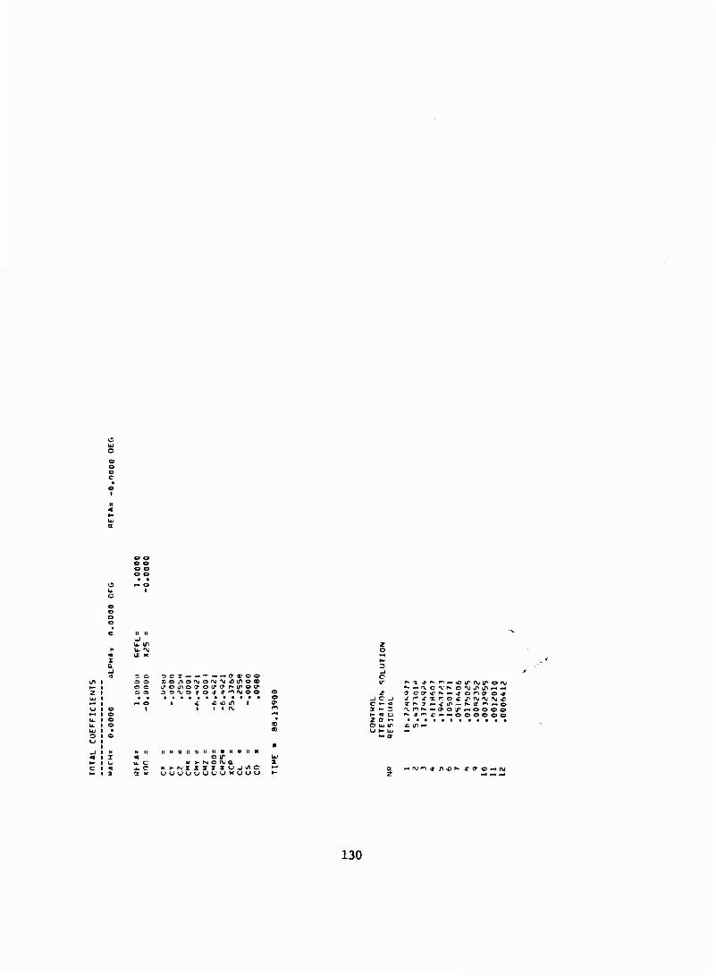
o o
c o
U. IT
o o ocx— — "~— — aafoo
-I c c •- I »- ^- «I z a o tw i^ * in —
II II II II II II 11 il II M H II O it
M >- N« o nj a — ryn^ &&** X^o—fV
130
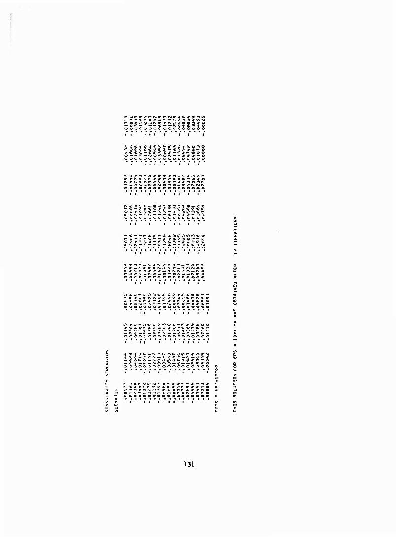
— c^—•*— — < — — fvo**m^o ooocooccooooeoooo
i i I I I i
o — —'^—njon<-fV—« — Of^C'* — O c ocoocer ooooocooo
o ooooooc ceoooeoee
i i i
c cccccccccccccccc
I I I I z o
cccccccc ccoccccoo
I I I I
occccoccocccccooe
i » i
O OCOOOOCOOOCOCOOOO
II f • I I I I
a UJ z
or o
.j o*.of*a:ir>fi4. ** — **c^x *--
— f\j^— fv—rvjcrv^- — c-«c—(r N — ocsocooocooooooooo
i i i
O 00000000000000300
in
I I • I I
Ü 2
I • I t I
131
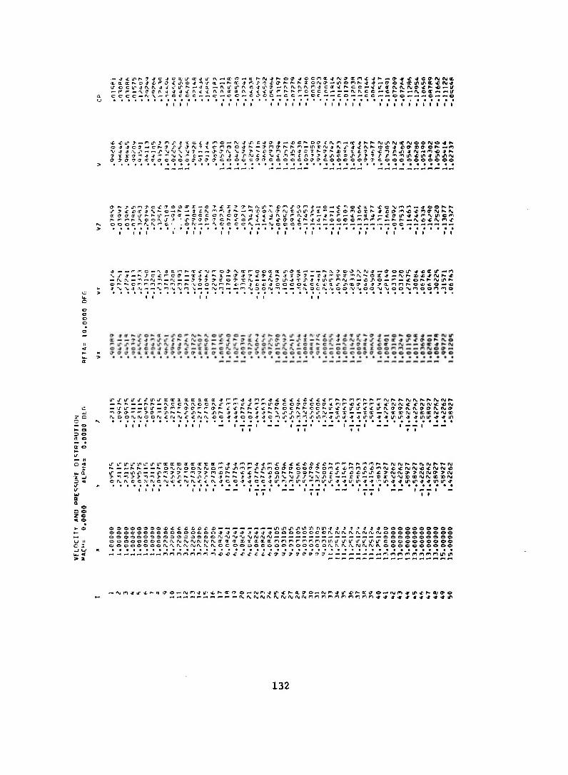
1 1 1 1 1 1 1 1 1 1 1 1 I 1 1 1 1 1 t I I I I
.£ SUIT r — n^j n.p t xcf -i fic— rv.*in D^a * — XICN-OIT rtv^ — T ^^^-ivirnjirivooftjo^f*-
a j'O'Ta'crTcTcooco'aa'a' cooc^ffcrccoocoja-cooccciff^coocooooooo
K. OOOCP^NfUT^Ot vO(\ — — ^COCCfV-^ — rUCCCC'-—— —— —i— — — 1-1— — — oc—•— — «-i«-«^- —
1 1 1 1 t t 1 1 1 1 1 t 1 1 1 t 1 1 1 1 I 1
©p-f^ccif. r-in^-nrir- \joof\jm^. * en ^ -t^j -jooooa, et*-a ITLPXIO •* ■jja.mn^-o^'to — *
1 1 1 1 1 t I
— o I- o D O n o a o
— ^N— — r^^- — (\ccfVfvocrvLrr-'^u~ir'^'^iro,crocya'Coa,*r]r'*icr'r^^^rvfv.'<<rrvf\i,**iv — U-LT — — u-u" — a',,"',roar-ra',fc^^^^sCtff^Kec^^cet^tr»r-firir«f*cirft.c?0'fv<va(T,iN.f\jff' -na>a-f*. T>0''^L^^-*-Xl/^'^,*- xr*. ^ -»■^^-j^^'vj^.r^'V^J'.'u — x x— — xx—rv;xxr\iAjeD«fMfVji!
1 1 1 1 1111 -• 1 1 1 1
— it
Lb a. a; _) 15 «
>-n*)j'j •^'*l>•*.Jll/l^.^J^^•^ ^ f-p*. j^r*.r* *1A%TJIA^'V(\JJI,I c —— r r-«— »I ■y'NjxX'%iAjxxi\i
1 1 1 1 1 1 t 1 1 1 —
u 11 c i -1 LJ
O3oooooo*x>c* £^£ j)—— — -• — -* — ^iniriTiJ^in^ nm-t -J » T •* ■» «-toooooooooo OOOCOOOOOOOOOCOO^ -»-J^ -J^-T^OOOOOOCCfV'fVrVifVirVfNjnjfVjoOOOOOOOOO OOOOOOOOOOOC OOOOi\jf\J '\('\j-\ji\jf\j(\j — — — —-«-•— — — -H— — — '-.-^ — 0000000000 ooooooocf\jf\.i\jixnjfvM(\.xa(ixxxxxfnnnr,nr. nrjiT'i/irirLTifirircooooooooo oooooooof\j^rv(\,(\)(\f\.(voc oooocoooooooc o (\. i\ (\.i\>r\;(\jivivoooooooooo
,nnnmr)r*'t~. >*>■£>&'£ iCiC-c t -c 9 y & & & & T 3 ■ «f"i**»nf^^)mfn^i/iift
— ftjri^ir^f^a ao — f\jri»u,'^;f*-crrro—f\jrt-jir*f*-a.(yo — rvn^ir^^-xu o^-cvm^iT'C'^CDcro
132
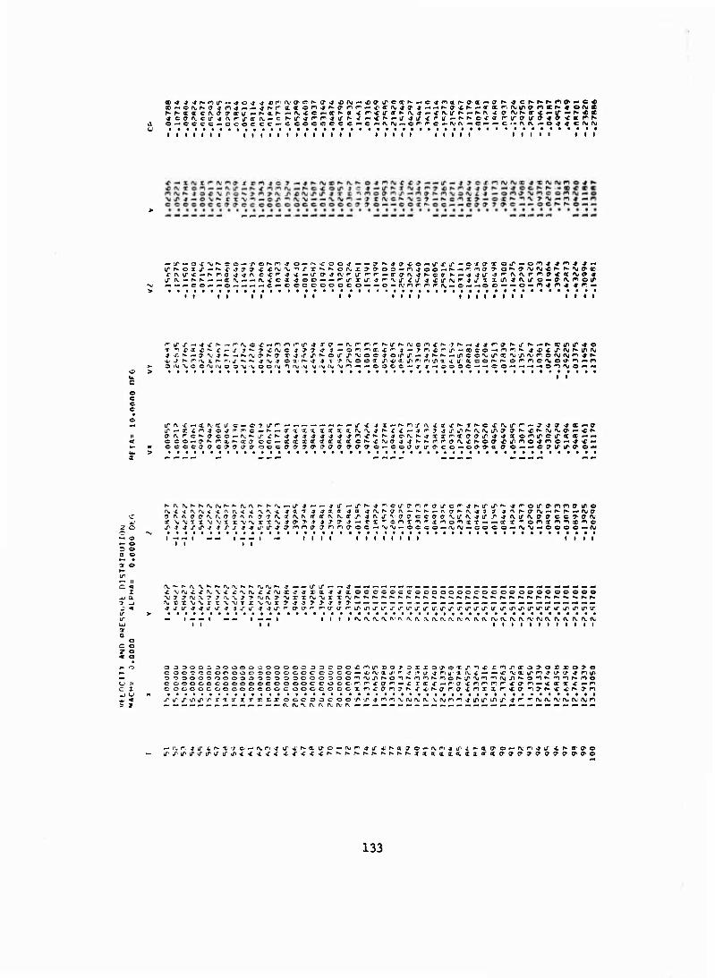
©-•cccc-iceoecc — ccoceocc—Cp-a^t-or^^C'-rvrv — c—^■C'-fvr\,—o^4Cf\jftj
I I i i I I i I I i i i i I I t I I I i I i I I t I I I i I I I I I I • I I
ir^-oix-^^-x^^* c 4s fV ^ *v ■/■*»*. K orvjx >0'OO'-n4oo — K«''. '■to1 7" o^-(^.'\J'\J*^•N■^J<^«
•v —««oo — — o — — « — c<—ccccoooeo — — o — fv.1 nfTf^i^rv. — o^-'-'OO'-•*o — n^n^^n^
i 1 1 1 1 t 1 1 1 1 III! I I I I I • • I III!
'll
IT ft: c "« ec (Vi ac IT c — © * IT f^ *- — •- — — — j-^ j a—Knj-A.xX'f^TKCsCfN.irf — T-jcy^x—a J-—xirr^o^-'f^c—N — crxxxixaxf\.'\j-»^fi—4^-J■4J'l^l^-fVl^Junffa^.^r^fVJ^,<^ — *r^ {y^f-c^ffco—r^^tTf^^j^^^sj^^mc^^-JOfVh'^xx^ffO'iji/i^^ionirei/'a «■«--• cco^-7'^TXKXcroc«-xxxxxxxxcN.Xf>jCT-jjp*h-rrr,fff\.Cf*-off*irir>o^no—^^ — occca,<yc!TJO'0'occefa'a,ff,cpa,a'Cfa'a,o — cocriri/'CT'co — ccr^acro — — e(Tirir<yo-"
x \,'uxx\j^jxr'\.''\.rT'\-Ji>> » *7-(y 4'-xz*,cnx'^,*j'*io'*ii"r — — xx**. oni^n»*^© x 4 -3 s J* s s s s s ■$ iri/-'* jr^na J r>nt?oc—•\i'\i«occo — r^fM«coeo«-f\<%j—oooc — (\j
N- O 3 O
t 1 — I I I I I I t I I I till
•- it ~ it c <
i JJ a
■£\jr\;xx%'v«£4:'\.'\.£^f\)3:44xa-»4xoccccccoooooocoocooooooooooo •VT ?i\j,'VTj^\.%.j->i\jrv7''\ixif\j'\jr x'\.''^^^^f,,«'^^-^'*-^-^->-'»-r»f,*^-»*-p*^^^r-r*K.^r».f^N. M rxxxr r \IMT X VM t > -» •» T > -t * ?•—-.-. — -.-. — -.-. — -■-.-.-. — ^-. — — _ — — — — — -. — -. 41/ u^44tfif-» »Xir4 4ir'*<T'CJ,'T r,crcr'T"iri/iiri/"LrL''irLriru". u^j-yiriTira iririririririfiriTirir
— i^.M| ^ ^. |MM| iii»fvfvn.fvft.f\'\af\rv(\,ft.fvn.aa(vrv(\.i\fvrv;ar\.rvfVfv<\. ll it i l l i l l i t i l i t
c o z o
OJ300-30000000000-SOOOO*mi/>DO>3XXOJ'OXun^^X:^J^X03,'OXXO>0 c oo-rceoooooooooocococo — •iJr\.•xJ■''' -J'^LT -J^UX rvx — — «c'vaLtr'^'Tir'J -jmui
cooooocooooocoooocc-occr', r'iffr^^x ixx— ra xf^^/rnx^m — xirx »c—n e:oocococoocjooocooocoooxrixo,'^?^x x^o-f. ff Xfr)xar'«£ff'*iy^<'^r*-^n
T if T ^ iT T X 1 !t X 1 f\j fv. 'V; f\j (\j f\j n
— d-ZifiTiririf iTiri^i/iTinx-txX'fxx'CXxr'^^^r^^Kf^Nf^xattxaa.xxxttCfaffcycT'O'a'O-ff'ff'©
133
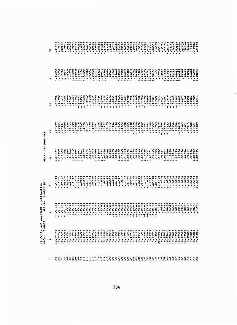
i i i i i i i i i i i i i i i i i i i i i i i l i • i t i
■r» x * r*- ^ »* cr^oir^oirrvjr^ (^JM(^l^xcao<, ccKXNiTO'njfVj^ ^ -> * « (TXt £io**'«~<-«9>ocDS){pi/>
^-c(? >ffj o — — — ox<ro-- — — off (?'ffa-*«-«-« — or*Nop- — -"«oo «» © — — nr', n(r«flD<^o —
1 l 1 l 1 l 1 1 • l l l l 1 III! I I
OtroX''^£4'\joxfV. x«-fv.x 3 — ^f^N-irof^LTinryx^ootM — r>cxx^ *'viro'\jo — trffeo»-— r'oaf^-'^rvjcxor-) — a. a. —m oxonjmj>x ff — o *ir*^"f^ ^-Of^O"*"!/". «Jo'Xfittiiro—irr. a)(i»(\i* — — SO — «--«O—— \i4-»'\j— -'O — —— —•— — \J— «onjvo—fVi\j— — — o — —C — ^f^OlTOOOO-*
1 1 l t l 1 1
r-^f^Off f ^4f\,r»-r*——r-.^ rx.j xxffff^f*' iri^cjo^xx^ xxf^-ff 4—©cxffX'r^ir'*^'^*aD — effaa crc^—cere xtrc —^-cffxa a c——ctr irtrac — — cffx xffo— — — —air^f^ffoo
? c 0 — 0 »~ 0 •s 0 a c or e 1- ir — 11 0 «
I aj a ;t _i j ■ 1/ w w a a
c 0 0 z e
f- -a r- M --oh-r-r-ff acoacr r-^^o^^o^r-fffaooffff^r, ^-cr-oooooocooeoooc f*-rv^ac—^-atrn' irur*.fvirf\r*—co — r»-fVirr\f^u,/,h-f\jirf\.'*- — cccocoocooccoo© 1/ c\ -tfirci^Jifff cr-r-cff x^r"xffff 1 f -jtrff cr-N'eff/'4''a,ffftNr'f*r»-r»- Kf^f^rw^.f^Kf* *xx—c^o-'i — r*-/-— — irf^ —■^ojocj'O'n—^[T — —^^«-no^ox-C x^cx^xxi-TNCXsC i\,*-c c 00 — ——c 00c oc — — — co cc———c OCOOO-" — — 00 — — — — — ———•-—■-•-— —
1 t 1 1 1 1 till 1 i 1 1 1 1 1 if\j\j\j,M-vj;\jM'>jMr\jf>j'\jf\jfy
ocoo4tf*44-*4-»'»-*4-»-»4-j-*-*4'»-»'***-»*-»>j*'»-*-*.»ofV'*iri\pffffX(Cfffff\Jir* — — — — j^/ixj^j'r,j*J,/i/>r*rrrr,rrtr'yj^iry. /«/»/i/ij^^xrxn — o — x^conno**» —
(\fVfVfV^J44'T4J-*-J-»-J* 44*? 3-9 -9 -9 $ -9 -3 \ 9 A -9
x/>n^off^c»rioooon»X's">oo7'f»-i;-jinccoonf*fv?-oooooooooooo30o a nj^r^-cT<?tJ ff *» n a a r, ^ tro- crffc-offffoa ^r-attr^^j crcrffooooooocooooooo
cr •£ r-iro^-r^j- ^4 LT— — y^ N ^ r-. —00 — r-ipf^ 4 x——iT-Jf^U ntwOirvirtflkPtf iT KKf- r-iririTir Ji^iff^^ajf^ — ^ — — 'v.^xrvjxffff-tfvxjrv— — ——(Vjajv^fffu-O1—^i/oxr^^xoir^-- r~, 4xrxxj"-J44-»444-»-»-jirxirirj-j'-»44-J44444-»XLnj,'oT?xr*.Kc***CP*-f^xff
134
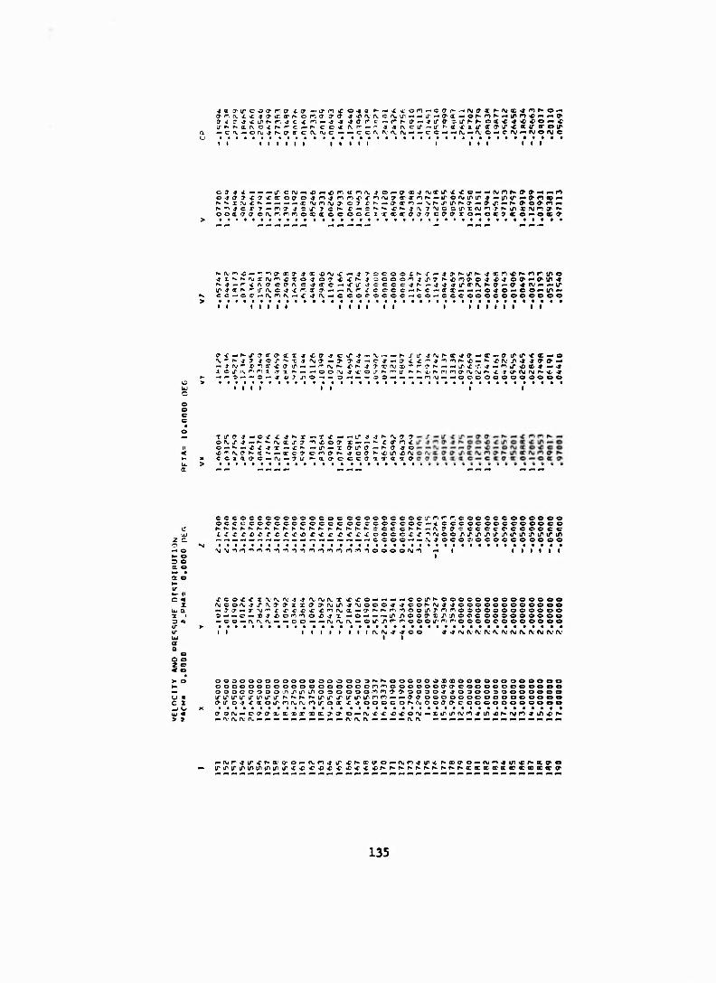
fftfC^iinKr. 4c ^ n — 4 4 -tare — ^f-.ff'-Ju'ar.a-Nr^oiic^o^o—«c
— c^. — oiv^^aor c (\.fve — — c ca (\fv fv»-^-cc — —try— ^o—cfX-' — MOfMe
i i t i i i i i i i i i i i i i i i i i
o -4 <T 9 -c ? >c tc Off o 4 n^nr^^^frirwaartrnh.—iroMtrir *—tf>ir»-«am» — f^f^x^i^N— — -* — « f\jnMT c7 ci^-«a'xt*>-.AJK4rirf*o-*ff'tf — ^^o^m — ooaffO'Cfx.r--, r-moxaceocci x««ffjff oaaxo—ocffffo^-oc»
f*'»—f*f\ ff cfff\ c-jtrc-'Nrir-jccccjr' —^^^irarfvr^ff—a^nj — — u* tfv,jet^'»-|/'(\jC-*<£«et ff-^-^-rvr- re cc c—^c —(ri^--.<-o4 0 — CO—u^*- cc—cc#-f\,r-, rv^-^^rv — c coc ococ — co — cceoooooooeooo
i i i i i i i i i i i i l i i i l • l l
ffc—^iTJcroai^ •so- -»ciT-j — 'V.-" — N'Xü- ^ryr^ff^ff — ac — ffirir»cc — o 'V.^r^^jje^'^T^rvja'—>'y-»—C'*—cr•£i'"■J',^'^^*•-»'*•*'(\.'l/^4-»{y(^*-
-.— -^-. — O — -JA/JJiO— — =>— — — OO — — — -.'•1,\| — —oooooooooooo
I I I I I I I
u. > et
;XXff ^COO1 x— — ^-ca-rw • X1^ —IT — X ff-lTff— f^ff 4C • ?i/ r-aff'C-ccffaxoxff'
o fv, ji j — h- r*- f\j x -. .■ O—*^ — -CX-fX— <f^ —IT — X O-lTff — f^ff 40 ^r-, (\af»-ff^- — xc? oriffr*. »»off h-»cir*r\j C C 5 Q, ^ C ^* rv ^ ^ " '^^ ^ '*' ^^ ^ **- r» ^c rT n n r*
cccocccooooococccooocoooxnr'r. cooeocooeooo occecocccococcc occ coc-ooc—^ ccc oeoocceooco f».KN.^^K^^^f».N.r^h- ^hfcf^fwf». see c^»*-—fvffffcccccc'cooccc ifri^orr-cr-rx) £ <£ c r^x-coocex^^njooj^irj^jiirinirir^inirift — .--..--.-.-.,-.,-.-.-,— — ._-,.-.-. — cooo — —^jocor.-oeoccooooo ■\j ■Vj -1 r i'n*)*i*)*in'nnt*inrnioooo'\j*i — i i i i i
a e w *- ii c <
X UJ a •x •
*coc<x^n.rv4-* A-nj^-X vcxo— — — «cc-LT^oooooooooceooo rvco'VJ'j-ixa-^ixa J1 Oj iT 4^000** sJCO^-ryJJCOOOOCOOOOOO — ^tr — TAj^r cx'^ii'Xi'^fv. x — cr^^f^nooiTTomooooooooooo© s — — c — Ti4.oonioxi.tx—o — — •^iT.nooffr.rjiooeooooooooo ^oe — rvafv — ^-co— — fVj'N.fv—otr^r^r^oooa1 ^r^oooocooooooo
i i i I t t 4 -» f\i fv<v cv ft. fv r\j r\. fv I>J iv iv
O o < e
c I -J c*
oooooooooooo ooo oo 3^^ooGooosx>eoooeoooooeo ooocoooooooooooooonrnooooootrcrcooooooooooo ooocoooon^iTiriooooooin^^ooao^^oaoooooooooo \f \s- & \i' \j \r & \jr t^ r*. r*- f*- & \f tTiTirirnr) — — ffff oooooooooooeeooo ffir c: -3 ■£ xoirrnr\,r\imu~ox x ^ooocoh-r^ooffffcooooeooooeo
135
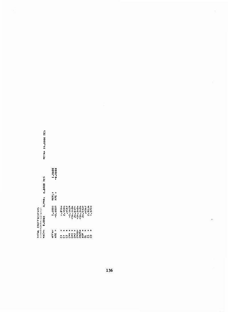
IS Ui c
c
U. IT M U. fV
m a K X a _i c a c
.n i 1 o o 1 o o 5 1 1 -=> o
w uj c
M II II H II II II II II II II II II H II Z « O IT
< u.C K>-r^ZXXZXU->(rO X T x UUUUUUUUXUUU
136
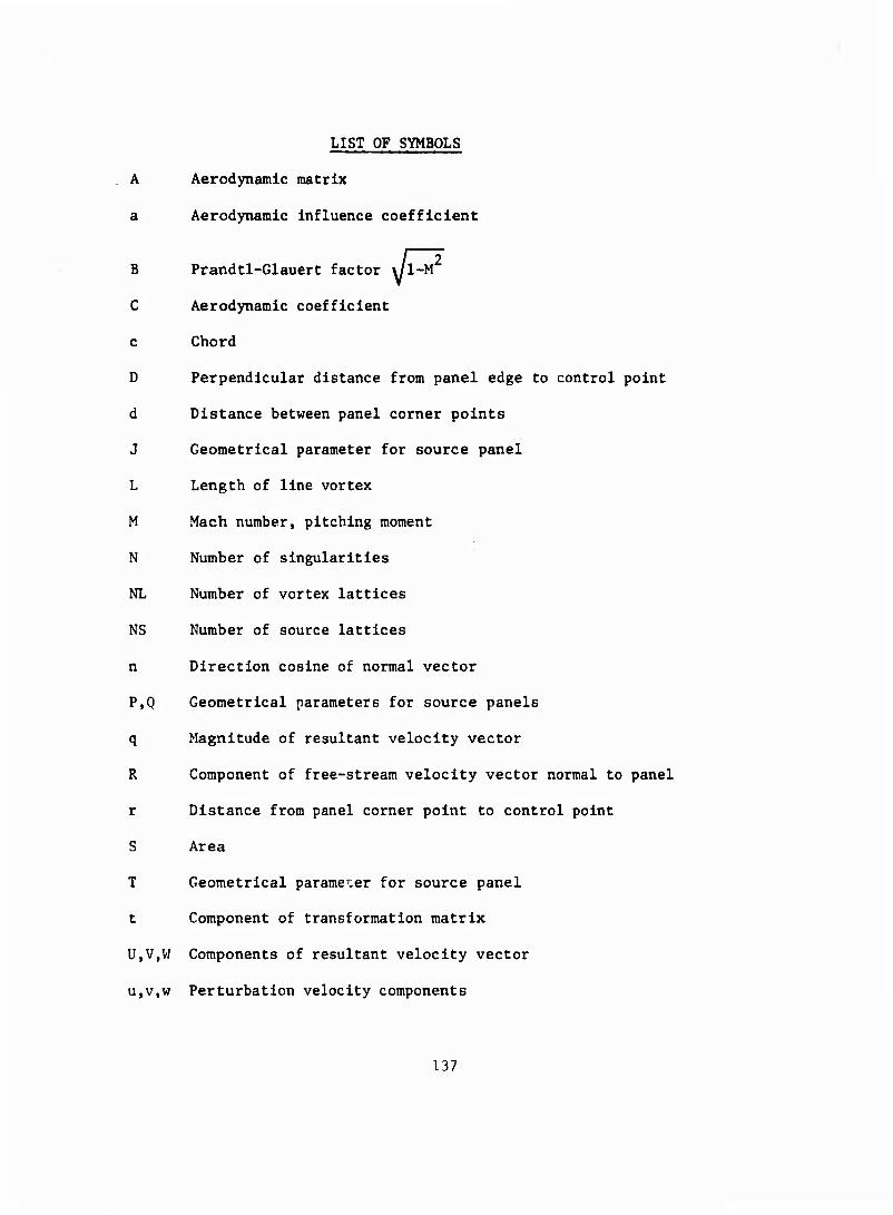
LIST OF SYMBOLS
A Aerodynamic matrix
a Aerodynamic influence coefficient
B Prandtl-Glauert factor \/l-M
C Aerodynamic coefficient
c Chord
D Perpendicular distance from panel edge to control point
d Distance between panel corner points
J Geometrical parameter for source panel
L Length of line vortex
M Mach number, pitching moment
N Number of singularities
NL Number of vortex lattices
NS Number of source lattices
n Direction cosine of normal vector
P,Q Geometrical parameters for source panels
q Magnitude of resultant velocity vector
R Component of free-stream velocity vector normal to panel
r Distance from panel corner point to control point
S Area
T Geometrical parameter for source panel
t Component of transformation matrix
U,V,W Components of resultant velocity vector
u,v,w Perturbation velocity components
137
List of Symbols (cont'd)
V Velocity vector magnitude
x,y,z Cartesian coordinates of point
a Angle of attack
ß Angle of yaw
Y Vortex strength
e Small reference value
K Ratio of specific heats for air
9 Angle between panel edge and line joining panel corner to control point
a Singularity strength
s Source strength
£,,T] Panel coordinates
Mathematical Symbols
-*■ Vector
| I Absolute value
x Cross product
• Scalar product
Average value
Matrix quantity
{ } Vector array
E Summation
! Integral
A Incremental value
138
List of Symbols (cont lil Sub sci tpts
a Analogous body
D Drag
1 Panel control point
j Panel corner point
L Lift
M Moment
P Pressure
s Source
S Side
V Vorcex
W Wing
X Axial
Y Lateral
Z Normal
x,y,z Reference axis direction
139